lg checkpointcodes u02.3 - lg klimaat solutions ... checkpoint-codes versie 2.4p-m vervangt u02.3.m...
TRANSCRIPT

LG Checkpoint-codes Versie 2.4P-M vervangt U02.3.M
LG
• BEFORE SERVICING THE UNIT, READ THE SAFETY PRECAUTIONS IN THE SERVICEMANUAL.
• ONLY FOR AUTHORIZED SERVICE PERSONNEL.
1
Hoofdstukindeling Single A (vloer- & plafond UV / cassette UT / kanaal UB)........................................04- Aan / Uit - Inverter UU..(W) - Variabel (aan/uit)..........................................................................................................26 AT-C.. / AT-H.. / LB-C.. / LB-D.. / LB-G.. / LB-H.. / LT-B.. / LT-C.. / LT-D.. / LT-E.. / LV-B.. / P..AH Multi-split ......................................................................................................................39- Inverter FM..AH - Variabel (aan/uit)..........................................................................................................92 M..AC/AH
2

- Multi-split tot 2005.......................................................................................................94 A2-C.. / A3-C.. / A2-H.. / A3-H.. / LM.. RAC...............................................................................................................................96- Standaard wandunit (aan/uit)......................................................................................97 LS-J.. / LS-K.. / LS-L.. / S..ACL / S..ACP / S..AH(P) / G..AH - ART COOL Deluxe / Panel (aan/uit)............................................................................97 LS-P.. / A09AH* / -12- / -18- / C07AH* / -09- / -12- - Standaard wandunit Inverter........................................................................................99 LS-N.. / LS-Q.. / LS-R.. / S..AN / S..AW - ART COOL Deluxe Inverter.........................................................................................101 C09AW* / C12AW* - ART COOL Deluxe Inverter.........................................................................................103 C18AW* / C24AW* -ART COOL Panel Inverter............................................................................................105 A09AW* / A12AW* / A09AW1 / A12AW1
LG
3
Single A (vloer- & plafond UV / cassette UT /
UB kanaal) UU..(W)
Inverter 1-fase (single-split)
Inverter 3-fase (Single-split)
Synchro (master/slave)
Variabel (aan/uit, single-split)
LG
4
LGE Internal Use Only
5. Trouble Shooting
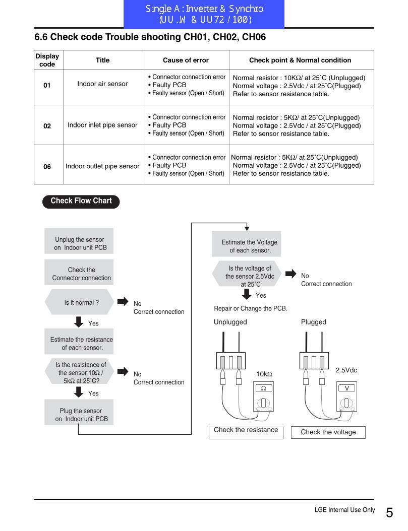
6.6 Check code Trouble shooting CH01, CH02, CH06
Ω
10kΩ
Unplugged Plugged
Check the resistance Check the voltage
V
2.5Vdc
Unplug the sensor on Indoor unit PCB
Estimate the Voltage of each sensor.
Is the voltage of the sensor 2.5Vdc
at 25˚C
Repair or Change the PCB.
Check theConnector connection
Is it normal ?
Estimate the resistance of each sensor.
Plug the sensor on Indoor unit PCB
Is the resistance of the sensor 10Ω /
5kΩ at 25˚C?
Yes
Yes
No Correct connection
Yes
No Correct connection
No Correct connection
Check Flow Chart
01
02
06
Indoor air sensor
Indoor inlet pipe sensor
Indoor outlet pipe sensor
• Connector connection error • Faulty PCB• Faulty sensor (Open / Short)
• Connector connection error • Faulty PCB• Faulty sensor (Open / Short)
• Connector connection error • Faulty PCB• Faulty sensor (Open / Short)
Normal resistor : 10KΩ/ at 25˚C (Unplugged)Normal voltage : 2.5Vdc / at 25˚C(Plugged)Refer to sensor resistance table.
Normal resistor : 5KΩ/ at 25˚C(Unplugged)Normal voltage : 2.5Vdc / at 25˚C(Plugged)Refer to sensor resistance table.
Normal resistor : 5KΩ/ at 25˚C(Unplugged)Normal voltage : 2.5Vdc / at 25˚C(Plugged)Refer to sensor resistance table.
Displaycode
Title Cause of error Check point & Normal condition
5
- 68 -Copyright ©2008 LG Electronics. Inc. All right reserved.Only for training and service purposes LGE Internal Use Only
5. Trouble Shooting
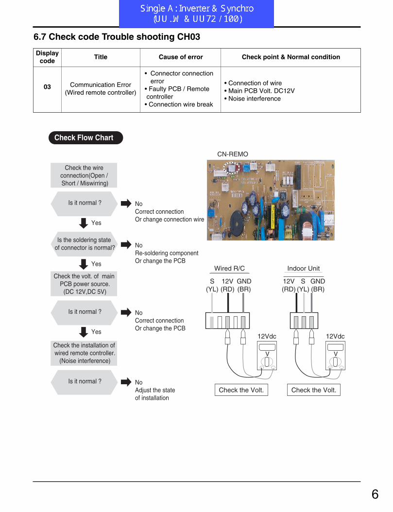
6.7 Check code Trouble shooting CH03
Check the Volt.
Indoor Unit
V
12Vdc
12V(RD)
S(YL)
GND(BR)
Check the Volt.
Wired R/C
V
12Vdc
S(YL)
12V(RD)
GND(BR)
Check the wire connection(Open / Short / Miswirring)
Is it normal ?
Check the volt. of main PCB power source.
(DC 12V,DC 5V)
Is the soldering state of connector is normal?
Yes
Yes
No Correct connectionOr change connection wire
Is it normal ?
Yes
No Correct connectionOr change the PCB
Check the installation of wired remote controller.
(Noise interference)
Is it normal ? No Adjust the state of installation
No Re-soldering componentOr change the PCB
Check Flow Chart
CN-REMO
03 Communication Error(Wired remote controller)
• Connector connectionerror
• Faulty PCB / Remote controller• Connection wire break
• Connection of wire • Main PCB Volt. DC12V• Noise interference
Displaycode
Title Cause of error Check point & Normal condition
6

- 69 -Copyright ©2008 LG Electronics. Inc. All right reserved.Only for training and service purposes LGE Internal Use Only
5. Trouble Shooting
6.8 Check code Trouble shooting CH04
Check the wire connection (Open, Soldered poorly)
Drain pump check
Check drain tube installation
Is it normal ?
Check the level of water (Float moves top
position)
Is it normal ?
Check the wire connection (Open, Soldered poorly)
Is the float switch clean ?
Yes
Yes
No Check Drain Pump
Yes
No Correct connectionOr re-soldering PCB
Is the resistance of Drain Pump? Normal
( about 400Ω ) ?
Yes
No Change the Drain Pump
Is the drain pump clean ?
Yes
No Clean drain pump
No Clean float switch
Is the resistance of float switch normal
(short) ?
Yes
No Change the float switch
Is it normal ? No Correct connectionOr re-soldering PCB
Check Flow Chart
CN-Float
CN-Float
04 Drain pump/ Float switch
• Float switch open.(Normal : short)
• Water over flow
• The connection of wire (Drain pump/ Float switch) • Drain pump power input. (220V)• Drain tube installation.• Indoor unit installation. (Inclination)
Displaycode
Title Cause of error Check point & Normal condition
7
- 70 -Copyright ©2008 LG Electronics. Inc. All right reserved.Only for training and service purposes LGE Internal Use Only
5. Trouble Shooting
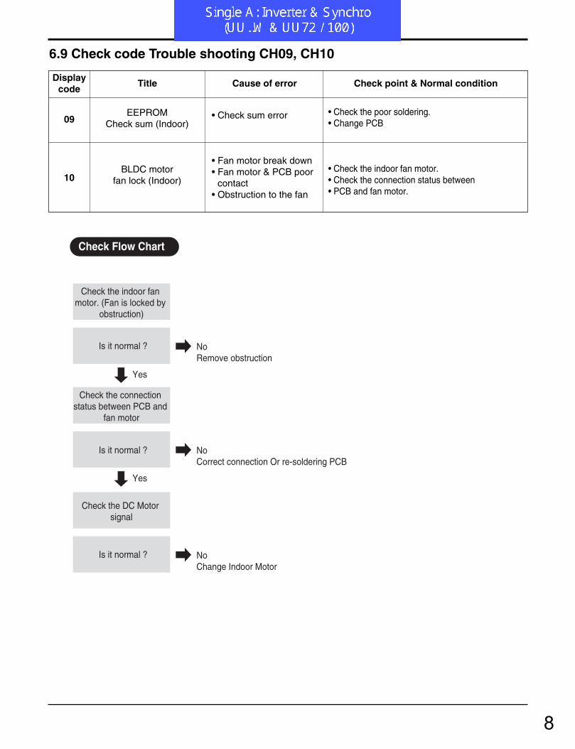
6.9 Check code Trouble shooting CH09, CH10
Check the indoor fan motor. (Fan is locked by
obstruction)
Is it normal ?
Yes
No Remove obstruction
Check the connection status between PCB and
fan motor
Is it normal ?
Yes
No Correct connection Or re-soldering PCB
Check the DC Motor signal
Is it normal ? No Change Indoor Motor
Check Flow Chart
09
10
EEPROMCheck sum (Indoor)
BLDC motorfan lock (Indoor)
• Check sum error
• Fan motor break down• Fan motor & PCB poor
contact• Obstruction to the fan
• Check the poor soldering.• Change PCB
• Check the indoor fan motor.• Check the connection status between • PCB and fan motor.
Displaycode
Title Cause of error Check point & Normal condition
8

- 71 -Copyright ©2008 LG Electronics. Inc. All right reserved.Only for training and service purposes LGE Internal Use Only
5. Trouble Shooting
6.10 Check code Trouble shooting CH05, CH53
Is the connection of GND,GND1,GND2, correctly connected?
Change PCB
CH05 is displayed at indoor unit, CH53 is displayed at outdoor unit.
Check the input power AC230V (Outdoor,
Indoor unit)
Is it normal ?( 230V ±10% )
Check the communication wires are correctly
connected.
Is it normal ?
Yes
Yes
No Needs electric work
Yes
No Correct connection
No Adjust the connection of wire Confirm the wire of "Live", "Neutral", "Signal"Check the resistance
between communication line and GND.
(Normal : Over 2MΩ)
Is connector for communication
correctly connected?
Is it normal ?
Yes
No Correct connection
Check Flow Chart
05/
53
Communication(Indoor↔Outdoor)
• The connector for trans-mission is disconnected.
• The connecting wiresare misconnected.
• The communication lineis break
• Outdoor PCB is abnormal.
• Indoor PCB is abnormal.
• Check power input AC 230V. (Outdoor, Indoor)• Check connector for transmission • Check wires are misconnecting. • Check transmission circuit of outdoor PCB • Check transmission circuit of indoor PCB
Displaycode
Title Cause of error Check point & Normal condition
9

- 72 -Copyright ©2008 LG Electronics. Inc. All right reserved.Only for training and service purposes LGE Internal Use Only
5. Trouble Shooting
6.11 Check code Trouble shooting CH21
Check Over load condition- Overcharging of refrigerant- Pipe Length- Condenser is blocked- Outdoor fan is locked
Is it normal ?(1 Ph : 230V ±10% 3 Ph : 400V ±10% )
Change Main PCB
Check the wire connection.(U,V,W)
Is it normal ?
Check the resistance of comp. (No difference at
each terminal)
Is it normal ?
Yes
Yes
No Correct connection
Yes
No Needs electric work
Check DC linkcapacitor Is it normal?
(Refer to belows)
Yes
No
No Change DC link capacitorOr Main PCB
Remove obstructionChange outdoor fan or motorChange refrigerant
No Change Compressor
Check the electricity leakageof the compressor.(Refer to comp check table)
Check the input power (Outdoor, Indoor unit)
Is it normal ?
Yes
No Change Compressor
Check Flow Chart
Dc link voltage table
Type Non operating Operating
1 Phase AUUW126C PSC DC300V ± 10% DC280V ± 10%
AUUW186C PSC DC300V ± 10% DC280V ± 10%
AUUW246D PFC DC300V ± 10% DC380V ± 10%
AUUW306D PFC DC300V ± 10% DC380V ± 10%
AUUW366D PFC DC300V ± 10% DC380V ± 10%
AUUW426D PFC DC300V ± 10% DC380V ± 10%
AUUW486D PFC DC300V ± 10% DC380V ± 10%
AUUW606D PFC DC300V ± 10% DC380V ± 10%
3 Phase AUUW368D PSC DC540V ± 10% DC500V ± 10%
AUUW428D PFC DC540V ± 10% DC680V ± 10%
AUUW488D PFC DC540V ± 10% DC680V ± 10%
AUUW608D PFC DC540V ± 10% DC680V ± 10%
ModelDC Link Voltage
21 DC Peak• Instant over current• Over Rated current• Poor insulation of IPM
• An instant over current in the U,V,W phase- Comp lock- The abnormal connection of U,V,W
• Over load condition- Overcharging of refrigerant- Pipe length.
• Poor insulation of compressor
Displaycode
Title Cause of error Check point & Normal condition
10
- 73 -Copyright ©2008 LG Electronics. Inc. All right reserved.Only for training and service purposes LGE Internal Use Only
5. Trouble Shooting
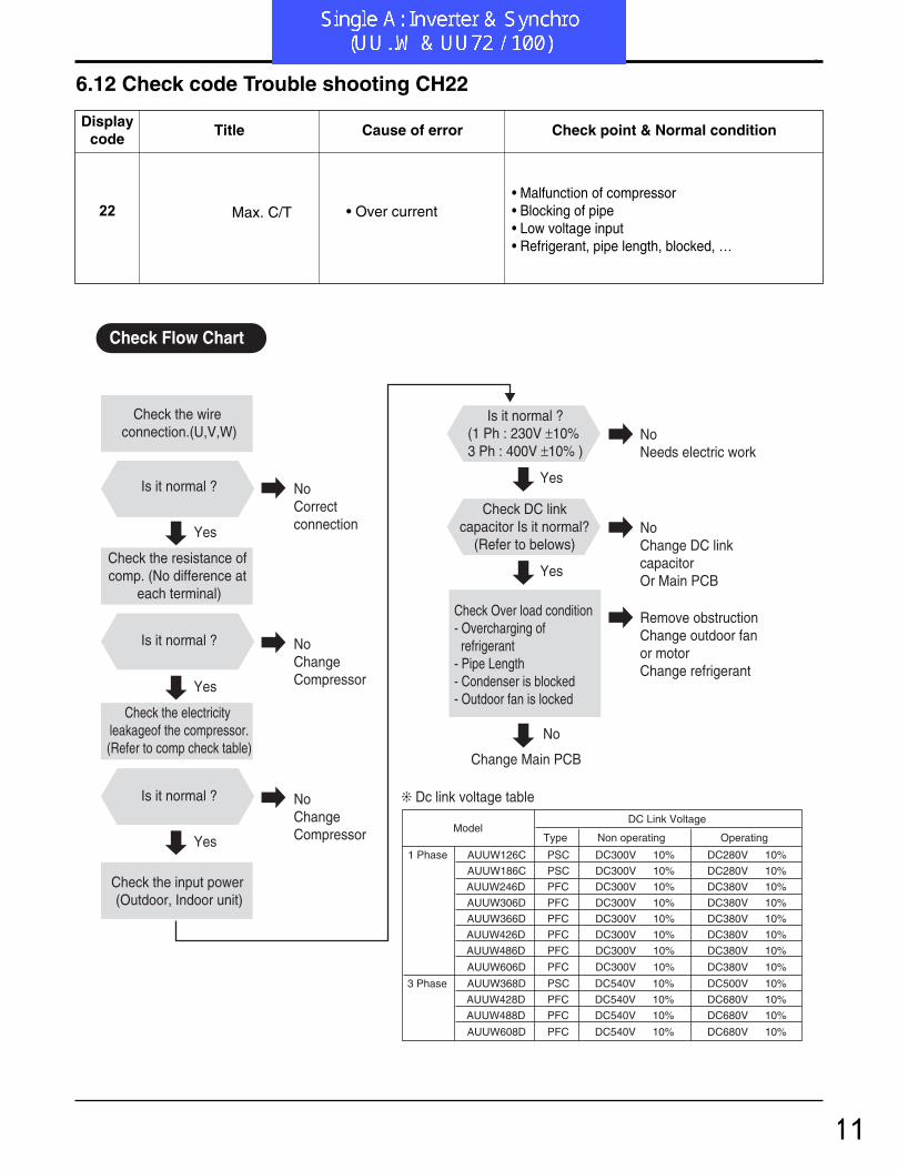
6.12 Check code Trouble shooting CH22
Check Over load condition- Overcharging of refrigerant- Pipe Length- Condenser is blocked- Outdoor fan is locked
Is it normal ?(1 Ph : 230V ±10% 3 Ph : 400V ±10% )
Change Main PCB
Check the wire connection.(U,V,W)
Is it normal ?
Check the resistance of comp. (No difference at
each terminal)
Is it normal ?
Yes
Yes
No Correct connection
Yes
No Needs electric work
Check DC linkcapacitor Is it normal?
(Refer to belows)
Yes
No
No Change DC link capacitorOr Main PCB
Remove obstructionChange outdoor fan or motorChange refrigerant
No Change Compressor
Check the electricity leakageof the compressor.(Refer to comp check table)
Check the input power (Outdoor, Indoor unit)
Is it normal ?
Yes
No Change Compressor
Check Flow Chart
Dc link voltage table
Type Non operating Operating
1 Phase AUUW126C PSC DC300V ± 10% DC280V ± 10%
AUUW186C PSC DC300V ± 10% DC280V ± 10%
AUUW246D PFC DC300V ± 10% DC380V ± 10%
AUUW306D PFC DC300V ± 10% DC380V ± 10%
AUUW366D PFC DC300V ± 10% DC380V ± 10%
AUUW426D PFC DC300V ± 10% DC380V ± 10%
AUUW486D PFC DC300V ± 10% DC380V ± 10%
AUUW606D PFC DC300V ± 10% DC380V ± 10%
3 Phase AUUW368D PSC DC540V ± 10% DC500V ± 10%
AUUW428D PFC DC540V ± 10% DC680V ± 10%
AUUW488D PFC DC540V ± 10% DC680V ± 10%
AUUW608D PFC DC540V ± 10% DC680V ± 10%
ModelDC Link Voltage
22 Max. C/T • Over current• Malfunction of compressor• Blocking of pipe• Low voltage input• Refrigerant, pipe length, blocked, …
Displaycode
Title Cause of error Check point & Normal condition
11
- 74 -Copyright ©2008 LG Electronics. Inc. All right reserved.Only for training and service purposes LGE Internal Use Only
5. Trouble Shooting
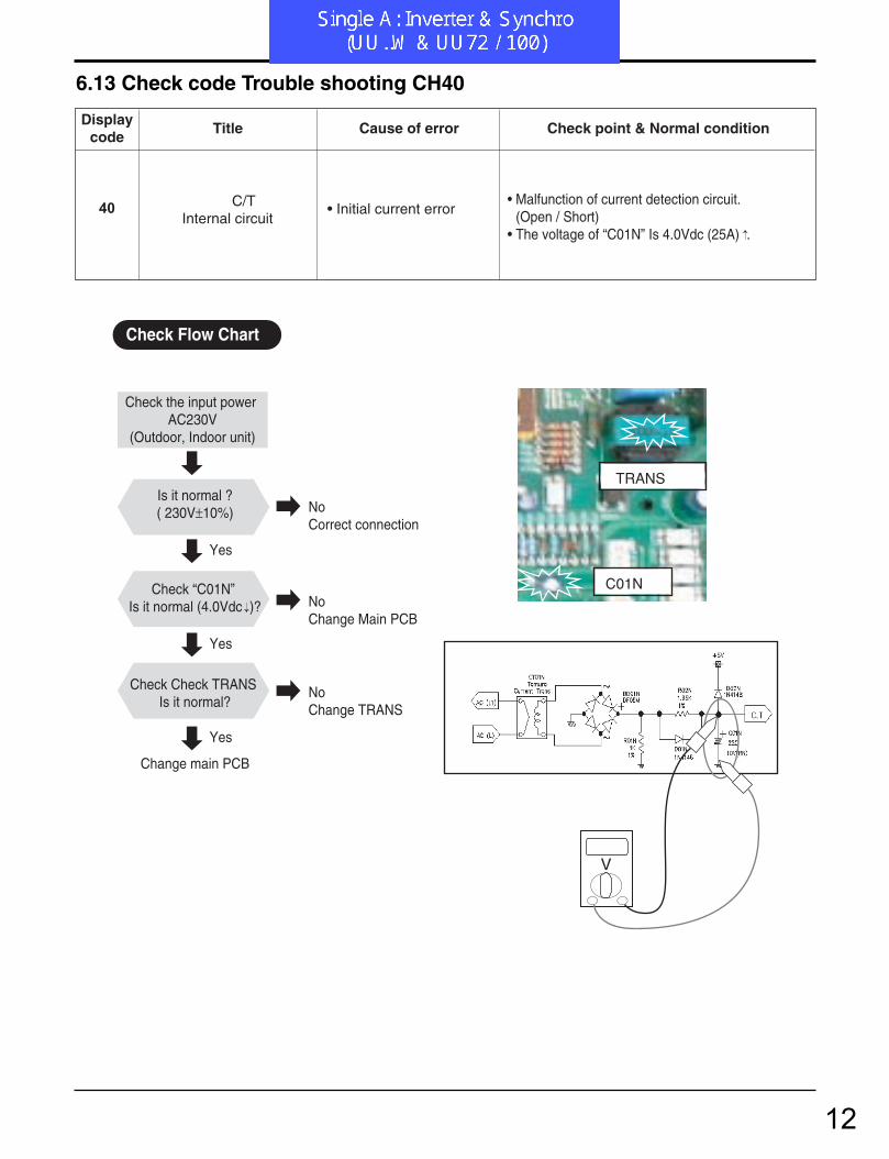
6.13 Check code Trouble shooting CH40
V
Check the input power AC230V
(Outdoor, Indoor unit)
Is it normal ?( 230V±10%)
Change main PCB
Check “C01N” Is it normal (4.0Vdc )?
Check Check TRANS Is it normal?
Yes
Yes
Yes
No Correct connection
No Change Main PCB
No Change TRANS
Check Flow Chart
TRANS
C01N
40 C/T Internal circuit
• Initial current error• Malfunction of current detection circuit.
(Open / Short)• The voltage of “C01N” Is 4.0Vdc (25A) .
Displaycode
Title Cause of error Check point & Normal condition
12
- 75 -Copyright ©2008 LG Electronics. Inc. All right reserved.Only for training and service purposes LGE Internal Use Only
5. Trouble Shooting
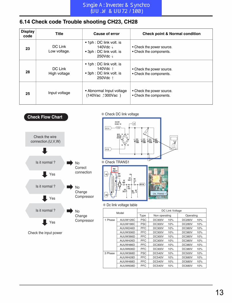
6.14 Check code Trouble shooting CH23, CH28
Check the wire connection.(U,V,W)
Is it normal ?
Is it normal ?
Yes
Yes
No Correct connection
No Change Compressor
Check the input power
Is it normal ?
Yes
No Change Compressor
Check Flow Chart
Dc link voltage table
Check TRANS1
Check DC link voltage
Type Non operating Operating
1 Phase AUUW126C PSC DC300V ± 10% DC280V ± 10%
AUUW186C PSC DC300V ± 10% DC280V ± 10%
AUUW246D PFC DC300V ± 10% DC380V ± 10%
AUUW306D PFC DC300V ± 10% DC380V ± 10%
AUUW366D PFC DC300V ± 10% DC380V ± 10%
AUUW426D PFC DC300V ± 10% DC380V ± 10%
AUUW486D PFC DC300V ± 10% DC380V ± 10%
AUUW606D PFC DC300V ± 10% DC380V ± 10%
3 Phase AUUW368D PSC DC540V ± 10% DC500V ± 10%
AUUW428D PFC DC540V ± 10% DC680V ± 10%
AUUW488D PFC DC540V ± 10% DC680V ± 10%
AUUW608D PFC DC540V ± 10% DC680V ± 10%
ModelDC Link Voltage
V
CN_TRANS 1
23
28
25
DC LinkLow voltage.
DC LinkHigh voltage
Input voltage
• 1ph : DC link volt. is140Vdc .
• 3ph : DC link volt. is250Vdc .
• 1ph : DC link volt. is140Vdc .
• 3ph : DC link volt. is250Vdc .
• Abnormal Input voltage(140Vac , 300Vac )
• Check the power source.• Check the components.
• Check the power source.• Check the components.
• Check the power source.• Check the components.
Displaycode
Title Cause of error Check point & Normal condition
13

- 76 -Copyright ©2008 LG Electronics. Inc. All right reserved.Only for training and service purposes LGE Internal Use Only
5. Trouble Shooting
6.15 Check code Trouble shooting CH24
Is the wire connection normal ?
Is the SVC Valve opened ?
Check the leakage of refrigerant.
Check Pressure of suction pipe
Check Pressure of discharge pipe
Is the soldering state of connector is
normal?
Yes
Yes
No Correct connection
No Re-soldering component
Yes
No Open SVC Valve
Is it normal ?
Change main PCB
Yes
No Re-vaccuming system & Re-charging
Check Flow Chart
CN_PRESS
Switch Low pressure switch High pressure switchSpec 0.03 Mpa 4.3 MpaModel AUUW126C AUUW246D
AUUW186C AUUW306DAUUW366DAUUW426DAUUW486DAUUW606DAUUW368DAUUW428DAUUW488DAUUW608D
Pressure switch table
24 Press S/W Open• Low / High press
S/W open.• Check the connection of “CN_PRESS”• Check the SVC V/V open.• Check the leakage of refrigerant.
Displaycode
Title Cause of error Check point & Normal condition
14
- 77 -Copyright ©2008 LG Electronics. Inc. All right reserved.Only for training and service purposes LGE Internal Use Only
5. Trouble Shooting
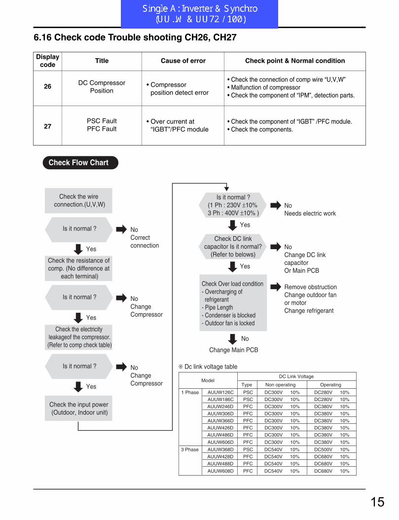
6.16 Check code Trouble shooting CH26, CH27
Check Over load condition- Overcharging of refrigerant- Pipe Length- Condenser is blocked- Outdoor fan is locked
Is it normal ?(1 Ph : 230V ±10% 3 Ph : 400V ±10% )
Change Main PCB
Check the wire connection.(U,V,W)
Is it normal ?
Check the resistance of comp. (No difference at
each terminal)
Is it normal ?
Yes
Yes
No Correct connection
Yes
No Needs electric work
Check DC linkcapacitor Is it normal?
(Refer to belows)
Yes
No
No Change DC link capacitorOr Main PCB
Remove obstructionChange outdoor fan or motorChange refrigerant
No Change Compressor
Check the electricity leakageof the compressor.(Refer to comp check table)
Check the input power (Outdoor, Indoor unit)
Is it normal ?
Yes
No Change Compressor
Check Flow Chart
Dc link voltage table
Type Non operating Operating
1 Phase AUUW126C PSC DC300V ± 10% DC280V ± 10%
AUUW186C PSC DC300V ± 10% DC280V ± 10%
AUUW246D PFC DC300V ± 10% DC380V ± 10%
AUUW306D PFC DC300V ± 10% DC380V ± 10%
AUUW366D PFC DC300V ± 10% DC380V ± 10%
AUUW426D PFC DC300V ± 10% DC380V ± 10%
AUUW486D PFC DC300V ± 10% DC380V ± 10%
AUUW606D PFC DC300V ± 10% DC380V ± 10%
3 Phase AUUW368D PSC DC540V ± 10% DC500V ± 10%
AUUW428D PFC DC540V ± 10% DC680V ± 10%
AUUW488D PFC DC540V ± 10% DC680V ± 10%
AUUW608D PFC DC540V ± 10% DC680V ± 10%
ModelDC Link Voltage
26
27
DC CompressorPosition
PSC FaultPFC Fault
• Compressorposition detect error
• Over current at“IGBT”/PFC module
• Check the connection of comp wire “U,V,W”• Malfunction of compressor• Check the component of “IPM”, detection parts.
• Check the component of “IGBT” /PFC module.• Check the components.
Displaycode
Title Cause of error Check point & Normal condition
15

4. Trouble Shooting
- 90 -Copyright ©2007 LG Electronics. Inc. All right reserved.Only for training and service purposes LGE Internal Use Only
29Inverter compressor over
currentInverter compressor inputcurrent is over 30A
1. Overload operation (Pipe clogging/Covering/EEV defect/Ref. over-charge)
2. Compressor damage(Insulation damage/Motordamage)
3. Input voltage low4. ODU inverter PCB assembly damage
Displaycode
Title Cause of error Check point & Normal condition
Error Diagnosis and Countermeasure Flow Chart
Is installation condition normal?
No
Yes
Yes
Yes
Recheck power and installation condition
1. Check Pipe clogging/distortion2. Check Covering (Indoor/Outdoor Unit)3. Check EEV connector assemble condition/normal operation4. Check refrigerant pressure Reassemble or manage if abnormality found
Yes
Is input voltage normal?No Check
L~N phase is 220V ±15% Check connection condition and wiring if power is abnormal
Yes
Is inverter PCB assembly normal?
No Check inverter PCB assembly IPM normality Replace inverter PCB assembly
Are the resistance Between each phase and
insulation resistance of Inverter compressor normal?
No
1. Check resistance between each terminal of compressor (0.188 ±7%)2. Check insulation resistance between compressor terminal and pipe (over 50MΩ ) Replace compressor if abnormality found
Is compressor Wire connection condition normal?
No
1. Check inverter PCB assembly U,V,W connector connection condition2. Check wire disconnection and wiring3. Check compressor terminal connection condition (bad contact) Reassemble if abnormality found
16

- 78 -Copyright ©2008 LG Electronics. Inc. All right reserved.Only for training and service purposes LGE Internal Use Only
5. Trouble Shooting
6.17 Check code Trouble shooting CH32, CH33
32
33
D-pipe (Inverter)temp. high(105˚C )
D-pipe (Constant)temp. high(105˚C )
• Discharge sensor(Inverter) temp. high
• Discharge sensor(Cons.) temp. high
• Check the discharge pipe sensor for INV.• Check the install condition for over load.• Check the leakage of refrigerant.• Check the SVC V/V open. • Refer to sensor resistance table.
• Check the discharge pipe sensor for Cons.• Check the install condition for over load.• Check the leakage of refrigerant.• Check the SVC V/V open.• Refer to sensor resistance table.
Displaycode
Title Cause of error Check point & Normal condition
Is the resistance of the sensor is 200kΩ
at 25˚C?
Plug the sensor on Indoor unit PCB
Estimate the Voltage of each sensor.
Repair or Change the PCB.
Check Over load condition - Refrigerant leakage - Condenser is blocked - Outdoor fan is locked
Unplug the sensor on Outdoor unit PCB
Check theConnector connection
Estimate the resistance of each sensor.
Is it normal ?
Yes
Yes
No Remove obstructionChange outdoor fan or motorChange refrigerant
Yes
Yes
Yes
No Change the sensor
Is the voltage of the sensor is
4.5Vdc at 25˚CNo Change the sensor
No Correct connection
Check Flow Chart
17

4. Trouble Shooting
- 115 -Copyright ©2007 LG Electronics. Inc. All right reserved.Only for training and service purposes LGE Internal Use Only
39Transmission Error
Between (PFC Micom INV Micom)
Communication ErrorBetween PFC Micomand INV Micom.
1. Micom defect/Circuit defect2. Different Micom S/W Version3. ODU inverter PCB assembly damage
Displaycode
Title Cause of error Check point & Normal condition
Error Diagnosis and Countermeasure Flow Chart
Is Inverter PCB assembly normal? No
Replace inverter PCB assembly
Is PFC Micom & INV Micom S/W Program normal?
No Upgrade Micom Program
Yes
Yes
Recheck power and installation condition
18

- 79 -Copyright ©2008 LG Electronics. Inc. All right reserved.Only for training and service purposes LGE Internal Use Only
5. Trouble Shooting
6.18 Check code Trouble shooting CH41, CH44, CH45, CH46, CH47, CH65
4147
44
4546
65
D-pipe sensor(Inv)D-pipe sensor(Cons)
Air sensor
Condenser Pipe sensorSuction Pipe sensor
Heat sinksensor
• Connector connection error • Faulty PCB• Faulty sensor (Open / Short)
• Connector connection error • Faulty PCB• Faulty sensor (Open / Short)
• Connector connection error • Faulty PCB• Faulty sensor (Open / Short)
• Connector connection error • Faulty PCB• Faulty sensor (Open / Short)
• Normal resistor : 200KΩ/ at 25˚C (Unplugged)• Normal voltage : 4.5Vdc / at 25˚C (plugged)• Refer to sensor resistance table.
• Normal resistor : 10KΩ/ at 25˚C (Unplugged)• Normal voltage : 2.5Vdc / at 25˚C (plugged)• Refer to sensor resistance table.
• Normal resistor : 5KΩ/ at 25˚C (Unplugged)• Normal voltage : 2.5Vdc / at 25˚C (plugged)• Refer to sensor resistance table.
• Normal resistor : 5KΩ/ at 25˚C (Unplugged)• Normal voltage : 2.5Vdc / at 25˚C (plugged)• Refer to sensor resistance table.
Displaycode
Title Cause of error Check point & Normal condition
Ω
10kΩ
Unplugged Plugged
Check the resistance Check the voltage
V
2.5Vdc
Unplug the sensor on Indoor unit PCB
Estimate the Voltage of each sensor.
Is the voltage of the sensor is 4.5Vdc /
2.5Vdc at 25˚C
Repair or Change the PCB.
Check theConnector connection
Is it normal ?
Estimate the resistance of each sensor.
Plug the sensor on Indoor unit PCB
Is the resistance of theSensor is 200kΩ/10kΩ⁄
/5kΩ at 25˚C?
Yes
Yes
No Correct connection
Yes
No Change the sensor
No Change the sensor
Check Flow Chart
19
5. Trouble Shooting
- 80 -Copyright ©2008 LG Electronics. Inc. All right reserved.Only for training and service purposes LGE Internal Use Only
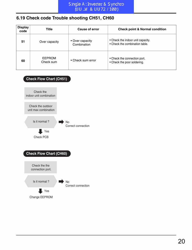
6.19 Check code Trouble shooting CH51, CH60
Check the indoor unit combination
Check the outdoor unit max combination
Is it normal ?
Check PCB
Change EEPROM
Check the the connection port.
Is it normal ?
Yes
Yes
No Correct connection
No Correct connection
Check Flow Chart (CH51)
Check Flow Chart (CH60)
51
60
Over capacity
EEPROMCheck sum
• Over capacityCombination
• Check sum error
• Check the indoor unit capacity.• Check the combination table.
• Check the connection port.• Check the poor soldering.
Displaycode
Title Cause of error Check point & Normal condition
20

4. Trouble Shooting
- 93 -Copyright ©2007 LG Electronics. Inc. All right reserved.Only for training and service purposes LGE Internal Use Only
52Transmission error
between (Inverter PCB Main PCB)
Main controller of Masterunit of Master unit can’treceive signal frominverter controller
1. Power cable or transmission cable is not connected
2. Defect of outdoor Main fuse/Noise Filter3. Defect of outdoor Main / inverter PCB
Displaycode
Title Cause of error Check point & Normal condition
Error diagnosis and countermeasure flow chart
Is transmission LED (Yellow) of inverter
compressor PCB on?
Yes
No Is noise filter or fusenormal?
Replace noise filter or fuseNo
Replace inverter compressor PCB
Is transmission cableconnected correctly?
Yes
NoRe-connect transmission cable
Is MAIN PCB normal?
Yes
NoReplace MAIN PCB
Replace inverter compressor PCB
Yes
Check Point- Check the Transmission connector and LED (Main & Inverter)
<MAIN PCB> <Inverter PCB>
48/56k
21
Troubleshooting Guide
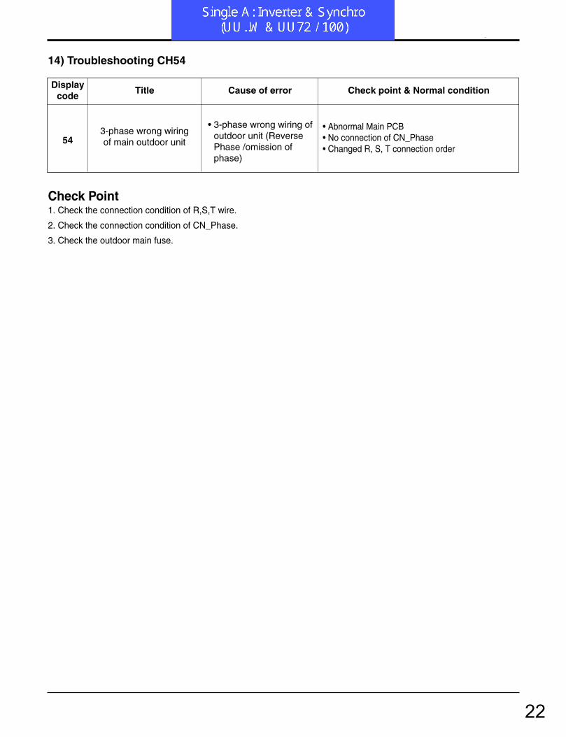
14) Troubleshooting CH54
543-phase wrong wiringof main outdoor unit
• 3-phase wrong wiring ofoutdoor unit (ReversePhase /omission ofphase)
• Abnormal Main PCB• No connection of CN_Phase• Changed R, S, T connection order
Displaycode
Title Cause of error Check point & Normal condition
Check Point1. Check the connection condition of R,S,T wire.
2. Check the connection condition of CN_Phase.
3. Check the outdoor main fuse.
22

5. Trouble Shooting
- 81 -Copyright ©2008 LG Electronics. Inc. All right reserved.Only for training and service purposes LGE Internal Use Only
6.20 Check code Trouble shooting CH61, CH62
Plug the sensor on Indoor unit PCB
Estimate the Voltage of each sensor.
Repair or Change the PCB.
Check Over load condition - Refrigerant leakage - Condenser is blocked - Outdoor fan is locked
Unplug the sensor on Outdoor unit PCB
Check theConnector connection
Estimate the resistance of each sensor.
Is it normal ?
Is the resistance of the Sensor is 5kΩ
/10kΩ at 25˚C?
Is the voltage of the sensor is 4.5Vdc /
2.5Vdc at 25˚C
Yes
Yes
No Remove obstructionChange outdoor fan or motorChange refrigerant
Yes
Yes
Yes
No Change the sensor
No Change the sensor
No Correct connection
Check Flow Chart
61
62
Condenserpipe sensortemp. high
Heat sink sensortemp. high
• condenser pipe sensordetected hightemp.(65˚C)
• heat sink sensor detected high temp.(85˚C)
• Check the load condition.• Check the sensor of Condenser pipe sensor.• Normal resistor : 5KΩ/ at 25˚C (Unplugged)• Normal voltage : 2.5Vdc / at 25˚C (Plugged)
• Check the load condition.• Check the sensor of heat sink.• Normal resistor : 10KΩ/ at 25˚C (Unplugged)• Normal voltage : 2.5Vdc / at 25˚C (Plugged)
Displaycode
Title Cause of error Check point & Normal condition
23

4. Trouble Shooting
- 102 -Copyright ©2007 LG Electronics. Inc. All right reserved.Only for training and service purposes LGE Internal Use Only
73AC input instant over cur-
rent error (Matter of software)
Inverter PCB input powercurrent is over 48A(peak)for 2ms
1. Overload operation (Pipe clogging/Covering/EEVdefect/Ref.overcharge)
2. Compressor damage (Insulation damage/Motor damage)
3. Input voltage abnormal (L, N)4. Power line assemble condition abnormal5. Inverter PCB assembly damage
(input current sensing part)
Displaycode
Title Cause of error Check point & Normal condition
Error Diagnosis and Countermeasure Flow Chart
No
1.Check Pipe clogging/distortion2.Check Covering (Indoor/Outdoor Unit)3.Check EEV connector assemble condition/normal operation4.Check refrigerant pressure Reassemble or manage if abnormality found
Is installation condition normal?
Is compressor Wire connection condition normal?
1.Check inverter PCB assembly U,V,W connector connection condition2.Check wire disconnection and wiring3.Check compressor terminal connection condition(bad contact) Reassemble if abnormality found
Is AC input Wire connectioncondition normal?
1.Check L,N connection condition2.Check wire disconnection and wiring Reassemble if abnormality found
Is inverter PCB assemblynormal?
Yes
No
Recheck power and installation condition
Yes
Yes
Yes
No
No
Yes
No Check L~N phase voltage is 220V ± 10% Check connection condition and wiring if power is abnormal
Is input voltage normal?
Check inverter PCB assembly IPM normality Replace inverter PCB assembly
24

16) Troubleshooting CH67, CH105
67
105
Outdoor fan lock
Communication errorbetween main PCB and
fan PCB
• Outdoor fan is not oper-ating
• Communication errorbetween main PCBand fan PCB
• Check the fan condition.• Check the fan connector
• Short or fusing of communication line• Poor outdoor unit PCB• Power input when the DC link capacitor discharges
Displaycode Title Cause of error Check point & Normal condition
Check Point• CH 671. Check the install condition for fan.
• CH 1051. Is communication line between the main PCB and the
fan PCB normal?2. Is the communication LED on?
Troubleshooting Guide
25
Single A
Aan / uit, Single-split AT-C.. / AT-H.. LB-C.. / LB-D.. / LB-E.. / LB-G.. / LB-H.. LT-B.. / LT-C.. / LT-D.. / LT-E.. LV-B.. P03AH / P05AH / P08AH
LG
26
Troubleshooting Guide
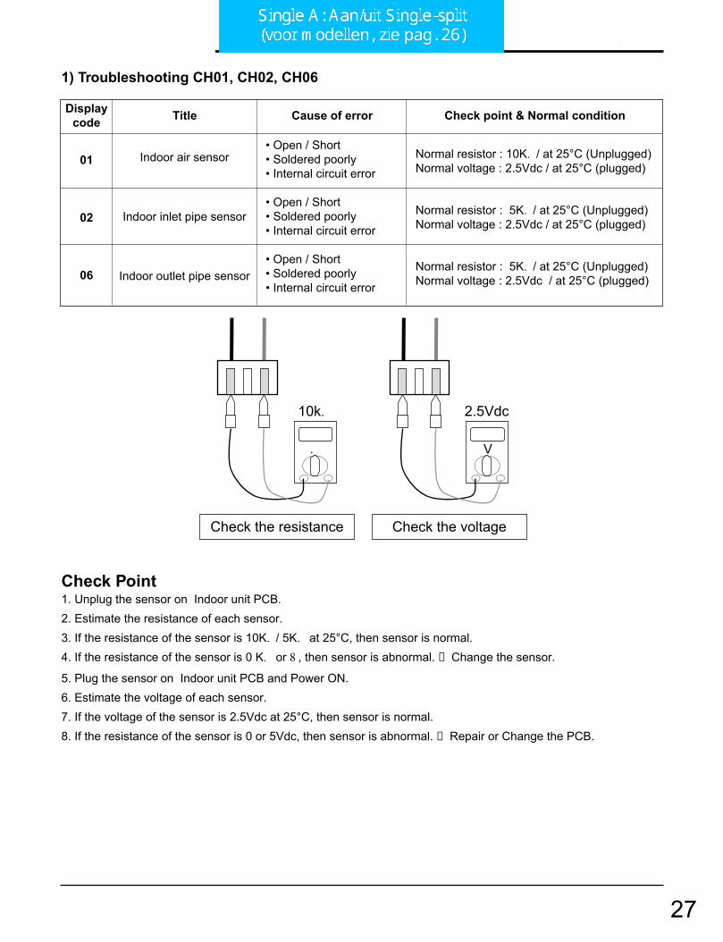
1) Troubleshooting CH01, CH02, CH06
.
10k.
Check the resistance Check the voltage
V
2.5Vdc
01
02
06
Indoor air sensor
Indoor inlet pipe sensor
Indoor outlet pipe sensor
• Open / Short• Soldered poorly• Internal circuit error
• Open / Short• Soldered poorly• Internal circuit error
• Open / Short• Soldered poorly• Internal circuit error
Normal resistor : 10K. / at 25°C (Unplugged)Normal voltage : 2.5Vdc / at 25°C (plugged)
Normal resistor : 5K. / at 25°C (Unplugged)Normal voltage : 2.5Vdc / at 25°C (plugged)
Normal resistor : 5K. / at 25°C (Unplugged)Normal voltage : 2.5Vdc / at 25°C (plugged)
Displaycode Title Cause of error Check point & Normal condition
Check Point1. Unplug the sensor on Indoor unit PCB.2. Estimate the resistance of each sensor.3. If the resistance of the sensor is 10K. / 5K. at 25°C, then sensor is normal.4. If the resistance of the sensor is 0 K. or 8 , then sensor is abnormal. →Change the sensor.
5. Plug the sensor on Indoor unit PCB and Power ON. 6. Estimate the voltage of each sensor.7. If the voltage of the sensor is 2.5Vdc at 25°C, then sensor is normal.8. If the resistance of the sensor is 0 or 5Vdc, then sensor is abnormal. →Repair or Change the PCB.
27

Troubleshooting Guide
2) Troubleshooting CH03
Check the Volt.
Indoor Unit
V
12Vdc
12V S GND
Check the Volt.
Wired R/C
V
12Vdc
12V S GNDCN-REMO
03 CommunicationWired R/C
• Open / Short• Wrong connection
• Connection of wire • Main PCB Volt. DC12V• Noise interference
Displaycode Title Cause of error Check point & Normal condition
Check Point1. Check the wire connection. (Open / Short) →Repair the connection
2. Check the soldering state of connector. (Soldered poorly) →Repair or Change the PCB.
3. Check the volt. Of main PCB power source. (DC 12V, DC 5V) →Repair or Change the main PCB.
4. Check the installation of wired remote controller. (Noise interference) →Adjust the state of installation
28

Troubleshooting Guide
3) Troubleshooting CH04
Check the resistance
.
0.
CN Float
CN-Float
CN-D/PUMP
04 Drain pump/ Float switch
• Float switch Open.(Normal : short)
• The connection of wire(Drain pump/ Float switch) • Drain pump power input. (220V)• Drain tube installation.• Indoor unit installation. (Inclination)
Displaycode Title Cause of error Check point & Normal condition
Check Point1. Check the wire connection. (Open, Soldered poorly) →Repair the connection or change the PCB.
2. Check the resistance of float switch (Abnormal : Open, Normal : short) →Check the float switch.
3. Check the level of water4. Check the volt. Of Drain pump power supply. (AC 230V) →Repair or Change the main PCB.
29

Troubleshooting Guide
4) Troubleshooting CH05, CH53
05/
53Communication
(Indoor →Outdoor) • Communication poorly
• Power input AC 220V. (Outdoor, Indoor)• The connector for transmission is disconnected.• The connecting wires are misconnected. • The GND1,2 is not connected at main GND.• The communication line is shorted at GND.• Transmission circuit of outdoor PCB is abnormal.• Transmission circuit of indoor PCB is abnormal.
Displaycode Title Cause of error Check point & Normal condition
Check Point1. Check the input power AC230V. (Outdoor, Indoor unit)2. Check the communication wires are correctly connected.
→Adjust the connection of wire
→Confirm the wire of “Live”, “Neutral”
3. Check the resistance between communication line andGND. (Normal : Over 2M. )
4. Check the connector for communication is correctly connected.
5. Check the connection of GND1, GND2, and main GND.6. If one indoor unit is operated normally, outdoor PCB is no
problem. →Check the another indoor unit.
* CH05 is displayed at indoor unit, CH53 is displayed at out-door unit.
30
Troubleshooting Guide
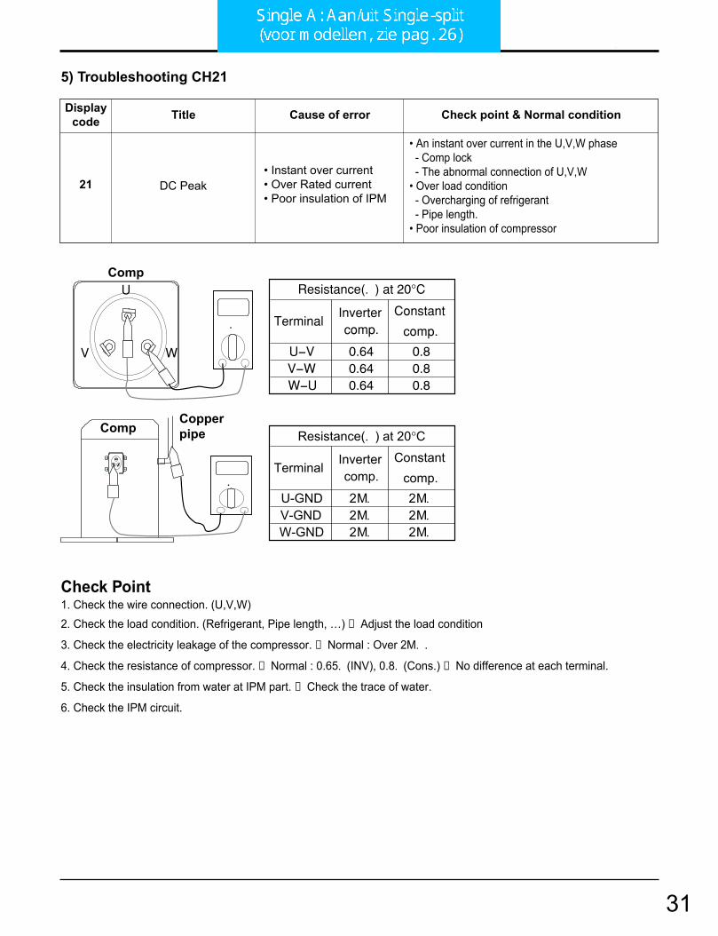
5) Troubleshooting CH21
.
CompCopperpipe
Resistance(. ) at 20°C
Resistance(. ) at 20°C
0.640.640.64
Invertercomp.
V-WW-U
U-V
Terminal
0.80.80.8
Constant
comp.
2M.2M.2M.
Invertercomp.
V-GNDW-GND
U-GND
Terminal
2M.2M.2M.
Constantcomp.
V
U
W
.
Comp
21 DC Peak• Instant over current• Over Rated current• Poor insulation of IPM
• An instant over current in the U,V,W phase- Comp lock- The abnormal connection of U,V,W
• Over load condition- Overcharging of refrigerant- Pipe length.
• Poor insulation of compressor
Displaycode Title Cause of error Check point & Normal condition
Check Point1. Check the wire connection. (U,V,W)2. Check the load condition. (Refrigerant, Pipe length, …) →Adjust the load condition
3. Check the electricity leakage of the compressor. →Normal : Over 2M. .
4. Check the resistance of compressor. →Normal : 0.65. (INV), 0.8. (Cons.) →No difference at each terminal.
5. Check the insulation from water at IPM part. →Check the trace of water.
6. Check the IPM circuit.
31

Troubleshooting Guide
108 Universal System Air Conditioner
6) Troubleshooting CH21, CH22
V
+-
+ -
+ -
21
22
Max. C/T
C/T Internal circuit
Over current (14A )
Initial current error
Malfunction of compressorBlocking of pipeLow voltage inputRefrigerant, pipe length, blocked, …
Malfunction of current detection circuit.(Open / Short)The voltage of “C01N” Is 4.0Vdc(25A) .
Displaycode Title Cause of error Check point & Normal condition
Check Point1. Check the power source.2. Check the fan operation is right.3. Check the current.4. Check the install condition.5. Check the internal circuit. (C/T, Diode, Resistor)

Troubleshooting Guide
110 Universal System Air Conditioner
8) Troubleshooting CH24, CH25
CN TRNAS1
CN PRESSTRANS150Hz, DC12V
24
25
Press S/W Open
Input voltage
• Low / High pressS/W open.
• Abnormal Input voltage(140Vac , 300Vac .
• Check the connection of “CN_Press”.• Check the components.
• Check the power source.• Check the components.
Displaycode Title Cause of error Check point & Normal condition
Check Point• CH 241. Check the connection of “CN_PRESS”2. Check the install condition for over load.3. Check the SVC V/V open.4. Check the leakage of refrigerant.
• CH 251. Check the power source.2. Check the components
(Trans1, B/Diode, Diode, Resistance)

Troubleshooting Guide
10) Troubleshooting CH32, CH33
LEV Openness(Pulse)
COMP Frequency(Hz)
Toff(105) °C
T1(90) °C
T2(95) °C
OFFNormal
OFF ControlNormal
Normal
Normal
D-Pipe temp.
32
33
D-pipe (Inverter)temp. high(105°C )
D-pipe (Constant)temp. high(105°C )
• Discharge sensor(Inverter) temp. high
• Discharge sensor(Cons.) temp. high
• Check the discharge pipe sensor for INV.• Check the install condition for over load.• Check the leakage of refrigerant.• Check the SVC V/V open.
• Check the discharge pipe sensor for Cons.• Check the install condition for over load.• Check the leakage of refrigerant.• Check the SVC V/V open.
Displaycode Title Cause of error Check point & Normal condition
Check Point• CH 321. Check the install condition for over load.2. Check the SVC V/V open. 3. Check the leakage of refrigerant.
• CH 331. Check the install condition for over load.2. Check the SVC V/V open. 3. Check the leakage of refrigerant.4. Check the constant compressor. (same with CH21)
34
Troubleshooting Guide
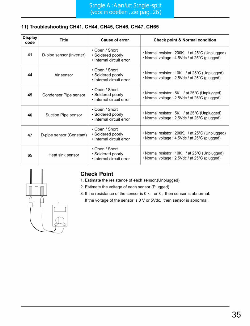
11) Troubleshooting CH41, CH44, CH45, CH46, CH47, CH65
.
41
44
45
46
47
65
D-pipe sensor (Inverter)
Air sensor
Condenser Pipe sensor
Suction Pipe sensor
D-pipe sensor (Constant)
Heat sink sensor
• Open / Short• Soldered poorly• Internal circuit error
• Open / Short• Soldered poorly• Internal circuit error
• Open / Short• Soldered poorly• Internal circuit error
• Open / Short• Soldered poorly• Internal circuit error
• Open / Short• Soldered poorly• Internal circuit error
• Open / Short• Soldered poorly• Internal circuit error
• Normal resistor : 200K. / at 25°C (Unplugged)• Normal voltage : 4.5Vdc / at 25°C (plugged)
• Normal resistor : 10K. / at 25°C (Unplugged)• Normal voltage : 2.5Vdc / at 25°C (plugged)
• Normal resistor : 5K. / at 25°C (Unplugged)• Normal voltage : 2.5Vdc / at 25°C (plugged)
• Normal resistor : 5K. / at 25°C (Unplugged)• Normal voltage : 2.5Vdc / at 25°C (plugged)
• Normal resistor : 200K. / at 25°C (Unplugged)• Normal voltage : 4.5Vdc / at 25°C (plugged)
• Normal resistor : 10K. / at 25°C (Unplugged)• Normal voltage : 2.5Vdc / at 25°C (plugged)
Displaycode Title Cause of error Check point & Normal condition
Check Point1. Estimate the resistance of each sensor.(Unplugged)2. Estimate the voltage of each sensor.(Plugged)3. If the resistance of the sensor is 0 k. or 8 , then sensor is abnormal.
If the voltage of the sensor is 0 V or 5Vdc, then sensor is abnormal.
35
Troubleshooting Guide
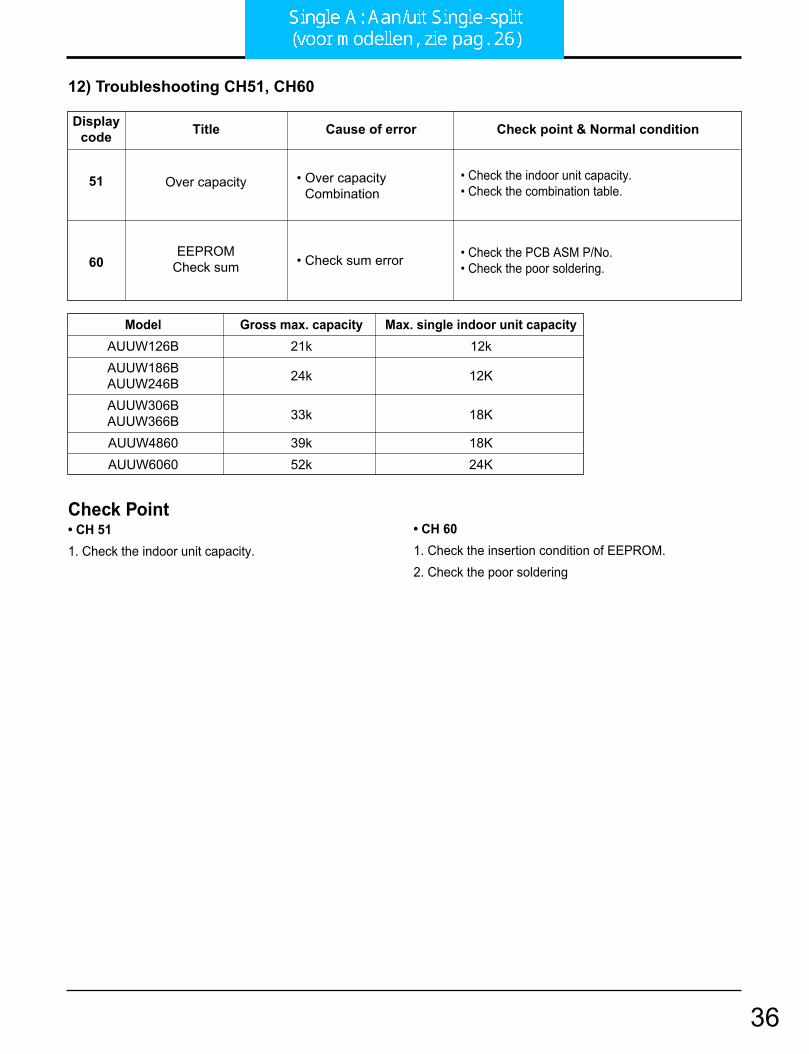
12) Troubleshooting CH51, CH60
51
60
Over capacity
EEPROMCheck sum
• Over capacityCombination
• Check sum error
• Check the indoor unit capacity.• Check the combination table.
• Check the PCB ASM P/No.• Check the poor soldering.
Displaycode Title Cause of error Check point & Normal condition
Check Point• CH 511. Check the indoor unit capacity.
• CH 601. Check the insertion condition of EEPROM.2. Check the poor soldering
Model Gross max. capacity Max. single indoor unit capacityAUUW126B 21k 12kAUUW186B 24k 12KAUUW246BAUUW306B
33k 18KAUUW366BAUUW4860 39k 18KAUUW6060 52k 24K
36
Troubleshooting Guide
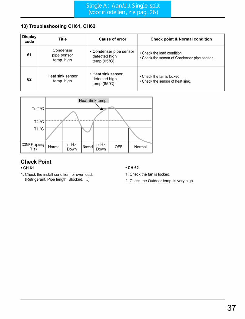
13) Troubleshooting CH61, CH62
61
62
Condenserpipe sensortemp. high
Heat sink sensortemp. high
• Condenser pipe sensordetected hightemp.(65°C)
• Heat sink sensor detected hightemp.(85°C)
• Check the load condition.• Check the sensor of Condenser pipe sensor.
• Check the fan is locked.• Check the sensor of heat sink.
Displaycode Title Cause of error Check point & Normal condition
Check Point• CH 611. Check the install condition for over load.
(Refrigerant, Pipe length, Blocked, …)
• CH 621. Check the fan is locked.2. Check the Outdoor temp. is very high.
COMP Frequency(Hz)
Toff °C
T1 °C
T2 °C
OFFNormal NormalNormal
Heat Sink temp.
37
Troubleshooting Guide
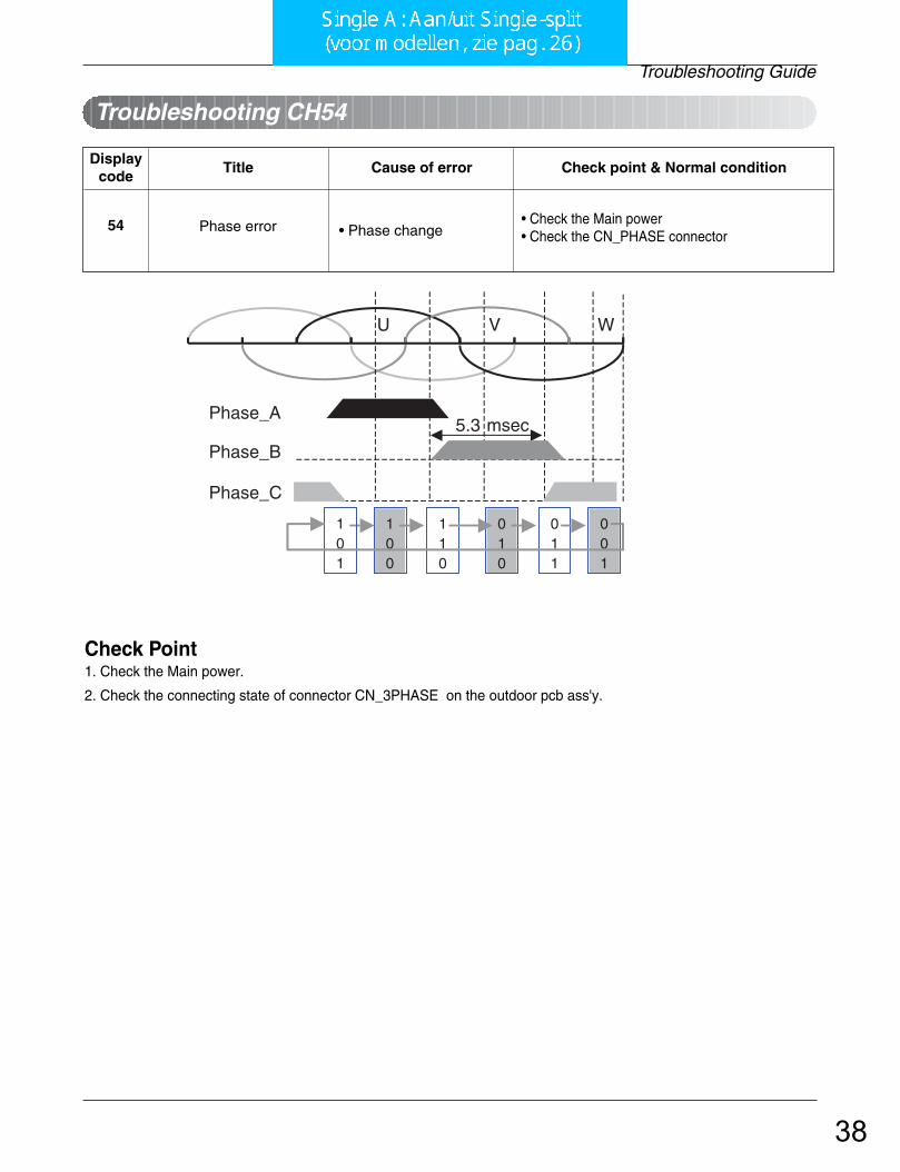
Troubleshooting CH54
54 Phase error • Phase change• Check the Main power• Check the CN_PHASE connector
Displaycode
Title Cause of error Check point & Normal condition
Check Point1. Check the Main power.
2. Check the connecting state of connector CN_3PHASE on the outdoor pcb ass'y.
100
001
U V W
Phase_A
Phase_B
Phase_C
5.3 msec
101
110
010
011
38
Multi-split Inverter FM..AH
LG
39

- 59 -Copyright ©2007 LG Electronics. Inc. All right reserved.Only for training and service purposes LGE Internal Use Only
4. Trouble Shooting
6.6 Troubleshooting Indoor Error
Ω
10kΩ
Check the resistance Check the voltage
V
2.5Vdc
01
02
06
Indoor air sensor
Indoor inlet pipe sensor
Indoor outlet pipe sensor
• Open / Short• Soldered poorly• Internal circuit error
• Open / Short• Soldered poorly• Internal circuit error
• Open / Short• Soldered poorly• Internal circuit error
Normal resistor : 10KΩ/ at 25°C (Unplugged)Normal voltage : 2.5Vdc / at 25°C (plugged)
Normal resistor : 5KΩ/ at 25°C (Unplugged)Normal voltage : 2.5Vdc / at 25°C (plugged)
Normal resistor : 5KΩ/ at 25°C (Unplugged)Normal voltage : 2.5Vdc / at 25°C (plugged)
Displaycode
Title Cause of error Check point & Normal condition
Check Point1. Unplug the sensor on Indoor unit PCB.
2. Estimate the resistance of each sensor.
3. If the resistance of the sensor is 10KΩ/ 5KΩ at 25°C, then sensor is normal.
4. If the resistance of the sensor is 0 KΩ or ∞, then sensor is abnormal. Change the sensor.
5. Plug the sensor on Indoor unit PCB and Power ON.
6. Estimate the voltage of each sensor.
7. If the voltage of the sensor is 2.5Vdc at 25°C, then sensor is normal.
8. If the resistance of the sensor is 0 or 5Vdc, then sensor is abnormal. Repair or Change the PCB.
40

- 60 -Copyright ©2007 LG Electronics. Inc. All right reserved.Only for training and service purposes LGE Internal Use Only
4. Trouble Shooting
Check the Volt.
Indoor Unit
V
12Vdc
12V S GND
Check the Volt.
Wired R/C
V
12Vdc
12V S GNDCN-REMO
03Communication
Wired R/C• Open / Short• Wrong connection
• Connection of wire • Main PCB Volt. DC12V• Noise interference
Displaycode
Title Cause of error Check point & Normal condition
Check Point1. Check the wire connection. (Open / Short) Repair the connection
2. Check the soldering state of connector. (Soldered poorly) Repair or Change the PCB.
3. Check the volt. Of main PCB power source. (DC 12V, DC 5V) Repair or Change the main PCB.
4. Check the installation of wired remote controller. (Noise interference) Adjust the state of installation
41

- 61 -Copyright ©2007 LG Electronics. Inc. All right reserved.Only for training and service purposes LGE Internal Use Only
4. Trouble Shooting
Check the resistance
Ω
0Ω
CN Float
CN-Float
CN-D/PUMP
04 Drain pump/ Float switch
• Float switch Open.(Normal : short)
• The connection of wire(Drain pump/ Float switch) • Drain pump power input. (220V)• Drain tube installation.• Indoor unit installation. (Inclination)
Displaycode
Title Cause of error Check point & Normal condition
Check Point1. Check the wire connection. (Open, Soldered poorly) Repair the connection or change the PCB.
2. Check the resistance of float switch (Abnormal : Open, Normal : short) Check the float switch.
3. Check the level of water
4. Check the volt. Of Drain pump power supply. (AC 230V) Repair or Change the main PCB.
42

- 62 -Copyright ©2007 LG Electronics. Inc. All right reserved.Only for training and service purposes LGE Internal Use Only
4. Trouble Shooting
6.7 Troubleshooting Outdoor ErrorFM15AH t/m FM25AH
05/
53
Communication(Indoor Outdoor)
• Communication poorly
• Power input AC 220V. (Outdoor, Indoor)• The connector for transmission is disconnected.• The connecting wires are misconnected. • The GND1,2 is not connected at main GND.• The communication line is shorted at GND.• Transmission circuit of outdoor PCB is abnormal.• Transmission circuit of indoor PCB is abnormal.
Displaycode
Title Cause of error Check point & Normal condition
Check Point1. Check the input power AC230V. (Outdoor, Indoor unit)
2. Check the communication wires are correctly connected.
Adjust the connection of wire
Confirm the wire of “Live”, “Neutral”
3. Check the resistance between communication line andGND. (Normal : Over 2MΩ)
4. Check the connector for communication is correctly connected.
5. Check the connection of GND1, GND2, and main GND.
6. If one indoor unit is operated normally, outdoor PCB is noproblem.
Check the another indoor unit.
* CH05 is displayed at indoor unit, CH53 is displayed at out-door unit.
43
4. Trouble Shooting
- 72 -Copyright ©2007 LG Electronics. Inc. All right reserved.Only for training and service purposes LGE Internal Use Only
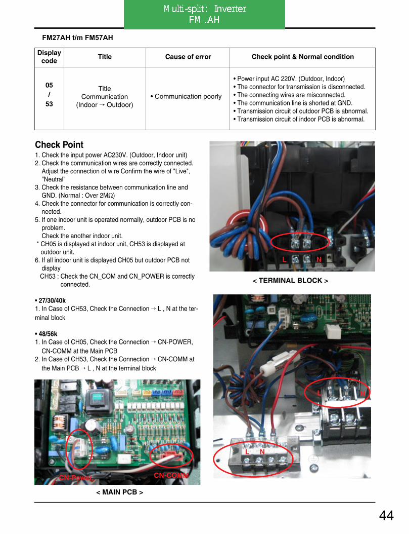
05/
53
TitleCommunication
(Indoor Outdoor)• Communication poorly
• Power input AC 220V. (Outdoor, Indoor)• The connector for transmission is disconnected.• The connecting wires are misconnected.• The communication line is shorted at GND.• Transmission circuit of outdoor PCB is abnormal.• Transmission circuit of indoor PCB is abnormal.
Displaycode
Title Cause of error Check point & Normal condition
Check Point1. Check the input power AC230V. (Outdoor, Indoor unit)2. Check the communication wires are correctly connected.
Adjust the connection of wire Confirm the wire of "Live","Neutral"
3. Check the resistance between communication line andGND. (Normal : Over 2MΩ)
4. Check the connector for communication is correctly con-nected.
5. If one indoor unit is operated normally, outdoor PCB is noproblem.Check the another indoor unit.
* CH05 is displayed at indoor unit, CH53 is displayed at outdoor unit.
6. If all indoor unit is displayed CH05 but outdoor PCB not display CH53 : Check the CN_COM and CN_POWER is correctly
connected.
• 27/30/40k1. In Case of CH53, Check the Connection L , N at the ter-minal block
• 48/56k1. In Case of CH05, Check the Connection CN-POWER,
CN-COMM at the Main PCB2. In Case of CH53, Check the Connection CN-COMM at
the Main PCB L , N at the terminal block
FM27AH t/m FM57AH
< TERMINAL BLOCK >
< MAIN PCB >
L N
N
L N
L N
CN-Power CN-COMM
44

4. Trouble Shooting
Copyright ©2007 LG Electronics. Inc. All right reserved.Only for training and service purposes LGE Internal Use Only
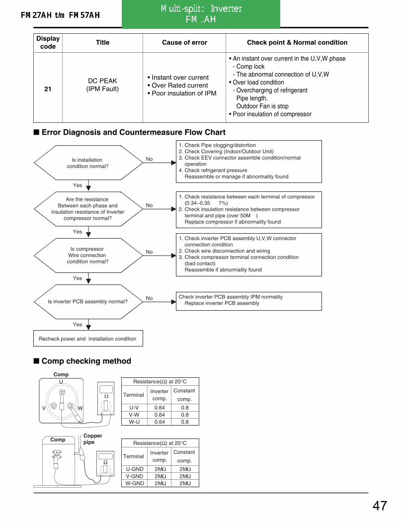
21DC PEAK(IPM Fault)
• Instant over current• Over Rated current• Poor insulation of IPM
• An instant over current in the U,V,W phase- Comp lock- The abnormal connection of U,V,W
• Over load condition- Overcharging of refrigerant
Pipe length.Outdoor Fan is stop
• Poor insulation of compressor
Displaycode
Title Cause of error Check point & Normal condition
Is installation condition normal?
No
Yes
Yes
Recheck power and installation condition
1. Check Pipe clogging/distortion2. Check Covering (Indoor/Outdoor Unit)3. Check EEV connector assemble condition/normal operation4. Check refrigerant pressure Reassemble or manage if abnormality found
1. Check resistance between each terminal of compressor (1.083~1.123Ω ±5%) 2. Check insulation resistance between compressor terminal and pipe (over 50M ) Replace compressor if abnormality found
Are the resistance Between each phase and
insulation resistance of Inverter compressor normal?
No
Yes
1. Check inverter PCB assembly U,V,W connector connection condition2. Check wire disconnection and wiring3. Check compressor terminal connection condition (bad contact) Reassemble if abnormality found
Is compressor Wire connection condition normal?
No
Yes
Check inverter PCB assembly IPM normality Replace inverter PCB assemblyIs inverter PCB assembly normal?
No
Error Diagnosis and Countermeasure Flow Chart
Comp checking method
Ω
CompCopperpipe
Resistance(Ω) at 20°C
Resistance(Ω) at 20°C
1.0961.1231.083
Invertercomp.
V-WW-U
U-V
Terminal
50MΩ50MΩ50MΩ
Invertercomp.
V-GNDW-GND
U-GND
Terminal
V
U
W
Ω
Comp
45

4. Trouble Shooting
Copyright ©2007 LG Electronics. Inc. All right reserved.Only for training and service purposes LGE Internal Use Only
CAUTIONIn case that the control box is opend and before checking electrical parts, it should be checked that theLED 01M, 02M turned off(wait 7 minutes after main power OFF), otherwise it may cause electrical shock.
1. Wait until inverter PCB DC voltage is discharged after main power off.
2. Pull out CN-L1(R), CN-L2(S), CN-L3(T) and CN-COMP Connector.
3. Set multi tester to resistance mode.
4. If the value between P and N terminal of IPM is short(0Ω) or open(hundreds MΩ), PCB needs to be replaced.(IPM damaged)
5. Set the multi tester to diode mode.
6. In case measured value is different from the table, PCB needs to be replaced.(PCB damaged).
27 26 25 24 23 22 21
P U V W Nu Nv Nw
0.4 ~ 0.6 V
27 26 25 24 23 22 21
P U V W Nu Nv Nw
0.4 ~ 0.6 V
PFC_IPM checkU, V, W R S T
46
4. Trouble Shooting
- 73 -Copyright ©2007 LG Electronics. Inc. All right reserved.Only for training and service purposes LGE Internal Use Only
21DC PEAK(IPM Fault)
• Instant over current• Over Rated current• Poor insulation of IPM
• An instant over current in the U,V,W phase- Comp lock- The abnormal connection of U,V,W
• Over load condition- Overcharging of refrigerant
Pipe length.Outdoor Fan is stop
• Poor insulation of compressor
Displaycode
Title Cause of error Check point & Normal condition
Is installation condition normal?
No
Yes
Yes
Recheck power and installation condition
1. Check Pipe clogging/distortion2. Check Covering (Indoor/Outdoor Unit)3. Check EEV connector assemble condition/normal operation4. Check refrigerant pressure Reassemble or manage if abnormality found
1. Check resistance between each terminal of compressor (0.34~0.35 7%)2. Check insulation resistance between compressor terminal and pipe (over 50M ) Replace compressor if abnormality found
Are the resistance Between each phase and
insulation resistance of Inverter compressor normal?
No
Yes
1. Check inverter PCB assembly U,V,W connector connection condition2. Check wire disconnection and wiring3. Check compressor terminal connection condition (bad contact) Reassemble if abnormality found
Is compressor Wire connection condition normal?
No
Yes
Check inverter PCB assembly IPM normality Replace inverter PCB assemblyIs inverter PCB assembly normal?
No
Error Diagnosis and Countermeasure Flow Chart
Comp checking method
Ω
CompCopperpipe
Resistance(Ω) at 20°C
Resistance(Ω) at 20°C
0.640.640.64
Invertercomp.
V-WW-U
U-V
Terminal
0.80.80.8
Constant
comp.
2MΩ2MΩ2MΩ
Invertercomp.
V-GNDW-GND
U-GND
Terminal
2MΩ2MΩ2MΩ
Constant
comp.
V
U
W
Ω
Comp
47
4. Trouble Shooting
Copyright ©2007 LG Electronics. Inc. All right reserved.Only for training and service purposes LGE Internal Use Only
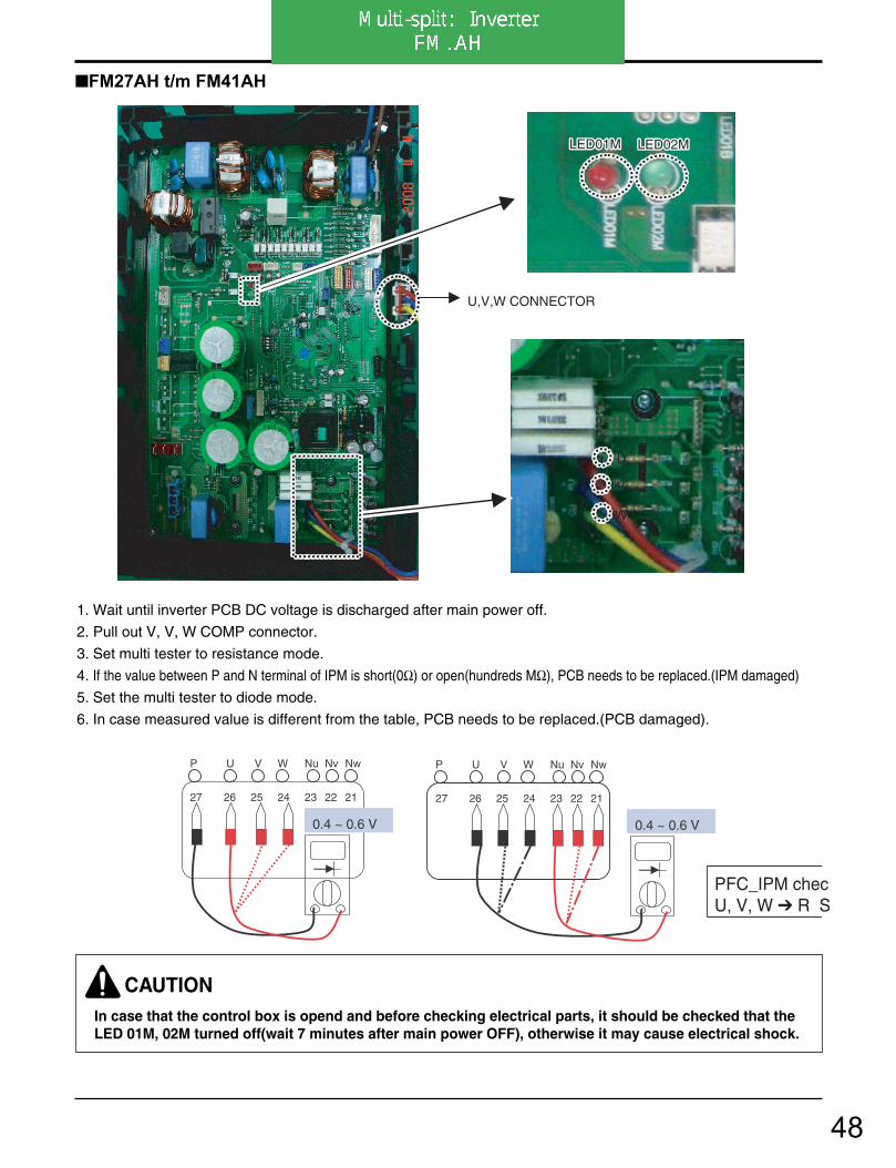
FM27AH t/m FM41AH
LED02MLED02M
U,V,W CONNECTOR
LED01MLED01M
U
V
W
U
V
W
LED02MLED01M
CAUTIONIn case that the control box is opend and before checking electrical parts, it should be checked that theLED 01M, 02M turned off(wait 7 minutes after main power OFF), otherwise it may cause electrical shock.
1. Wait until inverter PCB DC voltage is discharged after main power off.
2. Pull out V, V, W COMP connector.
3. Set multi tester to resistance mode.
4. If the value between P and N terminal of IPM is short(0Ω) or open(hundreds MΩ), PCB needs to be replaced.(IPM damaged)
5. Set the multi tester to diode mode.
6. In case measured value is different from the table, PCB needs to be replaced.(PCB damaged).
27 26 25 24 23 22 21
P U V W Nu Nv Nw
0.4 ~ 0.6 V
27 26 25 24 23 22 21
P U V W Nu Nv Nw
0.4 ~ 0.6 V
PFC_IPM checU, V, W R S
48

4. Trouble Shooting
- 75 -Copyright ©2007 LG Electronics. Inc. All right reserved.Only for training and service purposes LGE Internal Use Only
FM49AH t/m FM57AH
CN(L)_BRWONCN(L)_BRWONCN(N)_BLUECN(N)_BLUE
U
V
W
U,V,W CONNECTORU,V,W CONNECTOR
LED01MLED01M LED02MLED02M
CN(L)_BRWONCN(N)_BLUE
U
V
W
U,V,W CONNECTOR
LED01M LED02M
CAUTIONIn case that the control box is opend and before checking electrical parts, it should be checked that theLED 01M, 02M turned off(wait 7 minutes after main power OFF), otherwise it may cause electrical shock.
1. Wait until inverter PCB DC voltage is discharged after main power off.
2. Pull out CN(L), CN(N) connectors and U,V,W COMP Connector.
3. Set multi tester to resistance mode.
4. If the value between P and N terminal of IPM is short(0Ω) or open(hundreds MΩ), PCB needs to be replaced.(IPM damaged)
5. Set the multi tester to diode mode.
6. In case measured value is different from the table, PCB needs to be replaced.(PCB damaged).
27 26 25 24 23 22 21
P U V W Nu Nv Nw
0.4 ~ 0.6 V
27 26 25 24 23 22 21
P U V W Nu Nv Nw
0.4 ~ 0.6 V
PFC_IPM checU, V, W R S
49
4. Trouble Shooting
- 108 -Copyright ©2007 LG Electronics. Inc. All right reserved.Only for training and service purposes LGE Internal Use Only
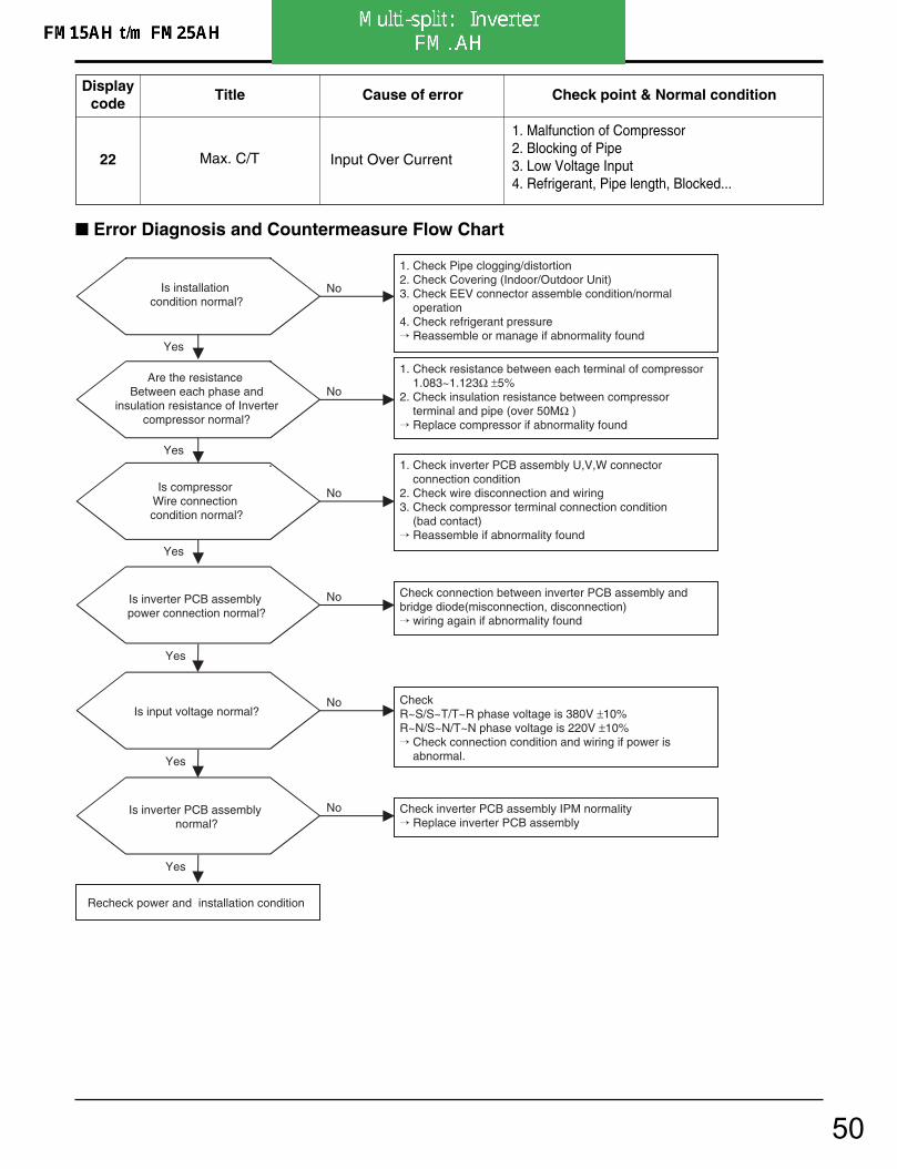
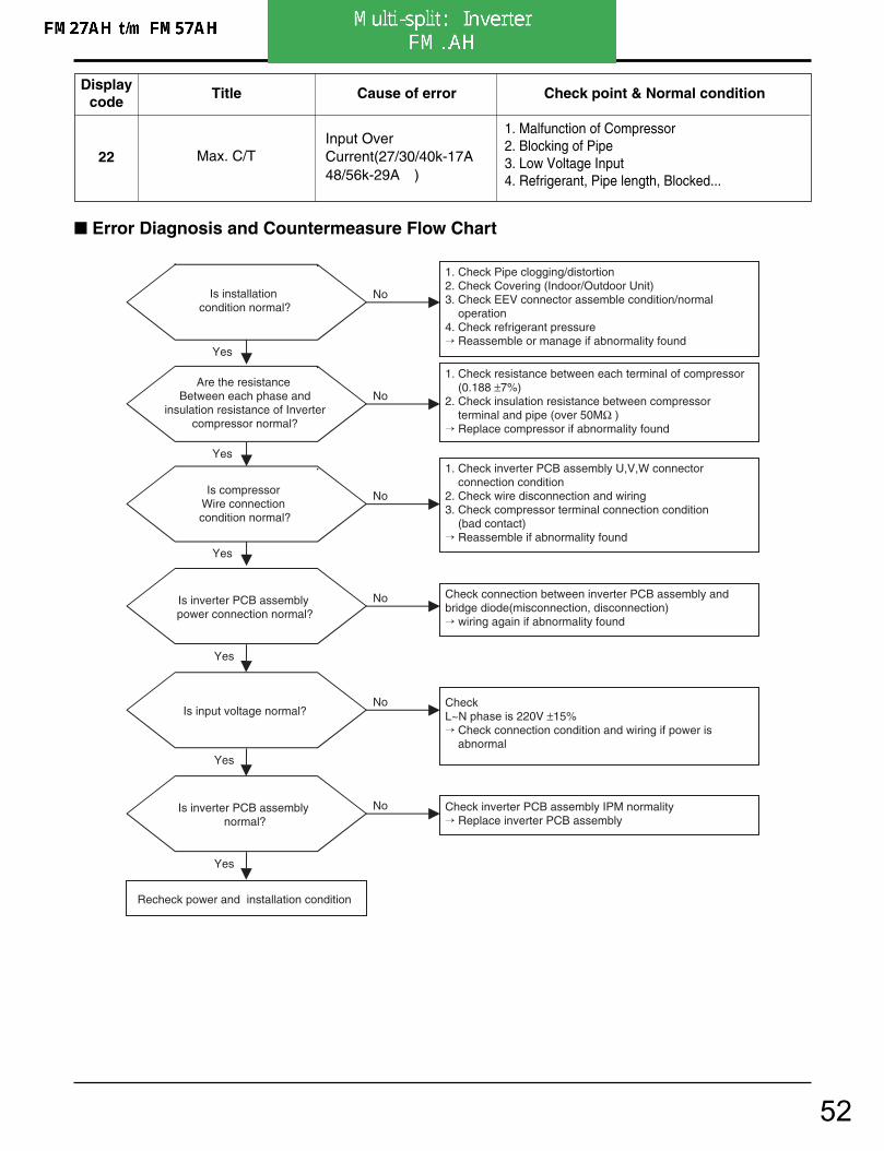
22 Max. C/T Input Over Current
1. Malfunction of Compressor2. Blocking of Pipe3. Low Voltage Input4. Refrigerant, Pipe length, Blocked...
Displaycode
Title Cause of error Check point & Normal condition
Error Diagnosis and Countermeasure Flow Chart
Is installation condition normal?
No
Yes
Yes
Yes
Recheck power and installation condition
Yes
1. Check Pipe clogging/distortion2. Check Covering (Indoor/Outdoor Unit)3. Check EEV connector assemble condition/normal operation4. Check refrigerant pressure Reassemble or manage if abnormality found
Is inverter PCB assembly power connection normal?
No Check connection between inverter PCB assembly and bridge diode(misconnection, disconnection) wiring again if abnormality found
Yes
Is input voltage normal?No Check
R~S/S~T/T~R phase voltage is 380V ±10%R~N/S~N/T~N phase voltage is 220V ±10% Check connection condition and wiring if power is abnormal.
Yes
Is inverter PCB assembly normal?
No Check inverter PCB assembly IPM normality Replace inverter PCB assembly
Are the resistance Between each phase and
insulation resistance of Inverter compressor normal?
No
1. Check resistance between each terminal of compressor 1.083~1.123Ω ±5%2. Check insulation resistance between compressor terminal and pipe (over 50MΩ ) Replace compressor if abnormality found
Is compressor Wire connection condition normal?
No
1. Check inverter PCB assembly U,V,W connector connection condition2. Check wire disconnection and wiring3. Check compressor terminal connection condition (bad contact) Reassemble if abnormality found
50
4. Trouble Shooting
- 109 -Copyright ©2007 LG Electronics. Inc. All right reserved.Only for training and service purposes LGE Internal Use Only
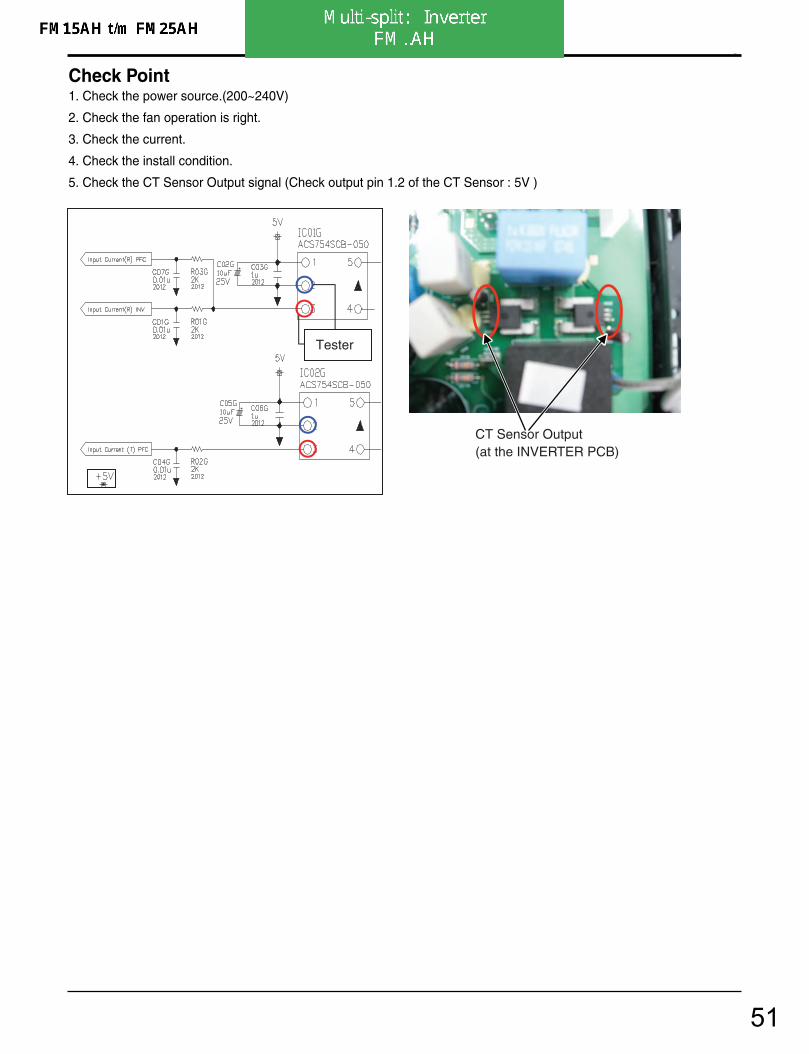
Check Point1. Check the power source.(200~240V)
2. Check the fan operation is right.
3. Check the current.
4. Check the install condition.
5. Check the CT Sensor Output signal (Check output pin 1.2 of the CT Sensor : 5V )
Tester
CT Sensor Output(at the INVERTER PCB)
51
4. Trouble Shooting
- 76 -Copyright ©2007 LG Electronics. Inc. All right reserved.Only for training and service purposes LGE Internal Use Only
22 Max. C/TInput OverCurrent(27/30/40k-17A↑48/56k-29A↑ )
1. Malfunction of Compressor2. Blocking of Pipe3. Low Voltage Input4. Refrigerant, Pipe length, Blocked...
Displaycode
Title Cause of error Check point & Normal condition
Error Diagnosis and Countermeasure Flow Chart
Is installation condition normal?
No
Yes
Yes
Yes
Recheck power and installation condition
Yes
1. Check Pipe clogging/distortion2. Check Covering (Indoor/Outdoor Unit)3. Check EEV connector assemble condition/normal operation4. Check refrigerant pressure Reassemble or manage if abnormality found
Is inverter PCB assembly power connection normal?
No Check connection between inverter PCB assembly and bridge diode(misconnection, disconnection) wiring again if abnormality found
Yes
Is input voltage normal?No Check
L~N phase is 220V ±15% Check connection condition and wiring if power is abnormal
Yes
Is inverter PCB assembly normal?
No Check inverter PCB assembly IPM normality Replace inverter PCB assembly
Are the resistance Between each phase and
insulation resistance of Inverter compressor normal?
No
1. Check resistance between each terminal of compressor (0.188 ±7%)2. Check insulation resistance between compressor terminal and pipe (over 50MΩ ) Replace compressor if abnormality found
Is compressor Wire connection condition normal?
No
1. Check inverter PCB assembly U,V,W connector connection condition2. Check wire disconnection and wiring3. Check compressor terminal connection condition (bad contact) Reassemble if abnormality found
52

4. Trouble Shooting
- 77 -Copyright ©2007 LG Electronics. Inc. All right reserved.Only for training and service purposes LGE Internal Use Only
Check Point1. Check the power source.(220V ±15%)2. Check the fan operation is right.3. Check the current.4. Check the install condition.5. Check the CT Sensor Output signal
(27/30/40k - Check output the CT Sensor : DC 2.5±0.2V) (48/56k - Check output pin 1.2 of the CT Sensor : 5V )
Vdc
< Input Power Source Check Point >
< Main PCB><CT Sensing Check Point>
<CT Sensing Check Point>< Inverter PCB>
53
4. Trouble Shooting
- 110 -Copyright ©2007 LG Electronics. Inc. All right reserved.Only for training and service purposes LGE Internal Use Only
23 DC Link Low voltage • DC Link volt is below300V
• Check point & Normal condition• Check the TAB1 is connect.• At not operating : DC Link voltage(260V↑ )• At Comp operating : DC Link voltage(500V↑ )
Displaycode
Title Cause of error Check point & Normal condition
Error Diagnosis and Countermeasure Flow Chart
Is DC Link voltage under 380V ?
No
Yes
Yes
Yes
Recheck power and installation condition
Yes
Check the DC link Voltage AD Input of Inverter PCBIf AD Input is strange, change the Inverter PCB(refer the next page.)
Is Inverter PCB Normal?No
Check connection from terminal block to Inverter PCB assembly CN_L1(R), CN_L2(S), CN_L3(T)
Replace inverter PCB assembly
Is input voltage normal ?No
R~S/S~T/T~R phase voltage is 400V ±10%R~N/S~N/T~N phase voltage is 220V ±10% Check connection condition and wiring if power is abnormal.
Is Inverter PCB assemblyPower connection normal?
No
54
4. Trouble Shooting
- 111 -Copyright ©2007 LG Electronics. Inc. All right reserved.Only for training and service purposes LGE Internal Use Only
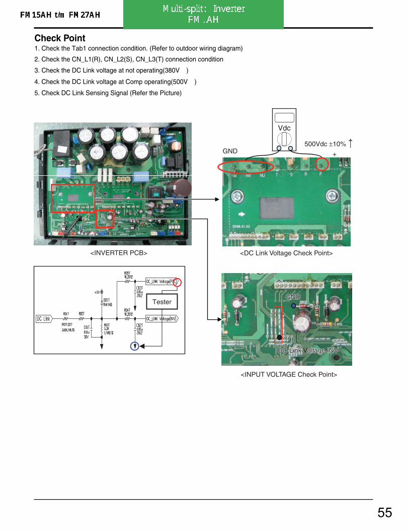
Check Point1. Check the Tab1 connection condition. (Refer to outdoor wiring diagram)
2. Check the CN_L1(R), CN_L2(S), CN_L3(T) connection condition
3. Check the DC Link voltage at not operating(380V↑ )
4. Check the DC Link voltage at Comp operating(500V↑ )
5. Check DC Link Sensing Signal (Refer the Picture)
<INVERTER PCB> <DC Link Voltage Check Point>
+ GND 500Vdc ±10%
DC LinkDC Link Voltage INV oltage INV
<INPUT VOLTAGE Check Point>
GND GND
DC Link Voltage INV
GND
Vdc
Tester
55
4. Trouble Shooting
- 78 -Copyright ©2007 LG Electronics. Inc. All right reserved.Only for training and service purposes LGE Internal Use Only
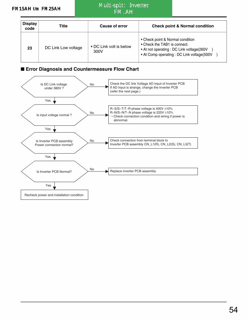
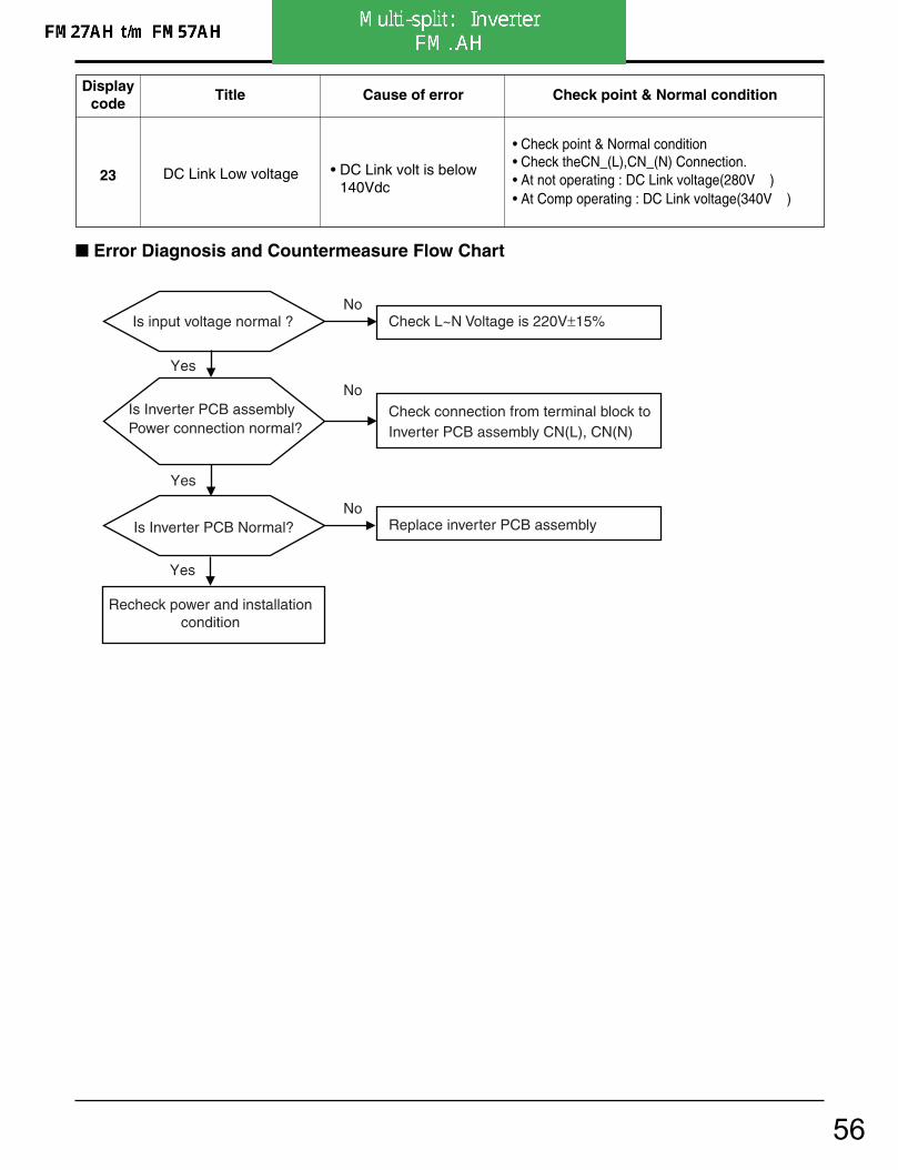
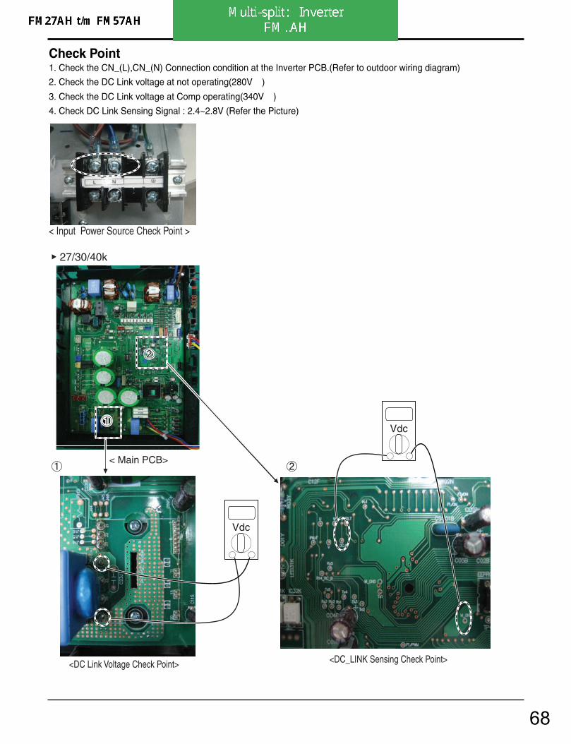
23 DC Link Low voltage • DC Link volt is below140Vdc
• Check point & Normal condition• Check theCN_(L),CN_(N) Connection.• At not operating : DC Link voltage(280V↑ )• At Comp operating : DC Link voltage(340V↑ )
Displaycode
Title Cause of error Check point & Normal condition
Error Diagnosis and Countermeasure Flow Chart
Is Inverter PCB assembly Power connection normal?
No Check connection from terminal block to Inverter PCB assembly CN(L), CN(N)
Yes
Is input voltage normal ? No
Yes
Is Inverter PCB Normal? No
Replace inverter PCB assembly
Recheck power and installationcondition
Yes
Check L~N Voltage is 220V±15%
56

4. Trouble Shooting
- 79 -Copyright ©2007 LG Electronics. Inc. All right reserved.Only for training and service purposes LGE Internal Use Only
Check Point1. Check the WCN_P(L),P(N) Connection condition at the Main PCB.(Refer to outdoor wiring diagram)
2. Check the DC Link voltage at not operating(280V↑ )
3. Check the DC Link voltage at Comp operating(340V↑ )
4. Check DC Link Sensing Signal :2.4~2.8V (Refer the Picture)
Vdc
< Main PCB>
<DC Link Voltage Check Point> <DC_LINK Sensing Check Point>
< Input Power Source Check Point >
27/30/40k
Vdc
57

4. Trouble Shooting
- 80 -Copyright ©2007 LG Electronics. Inc. All right reserved.Only for training and service purposes LGE Internal Use Only
Vdc
Vdc
< Inverter PCB>
<DC Link Voltage Check Point> <Connection Check Point>
GNDGND GND
GND
<DC_LINK Sensing Check Point>
N N
FM49AH t/m FM57AH
LL
DC_LINKDC_LINK DC_LINK
58
4. Trouble Shooting
- 81 -Copyright ©2007 LG Electronics. Inc. All right reserved.Only for training and service purposes LGE Internal Use Only
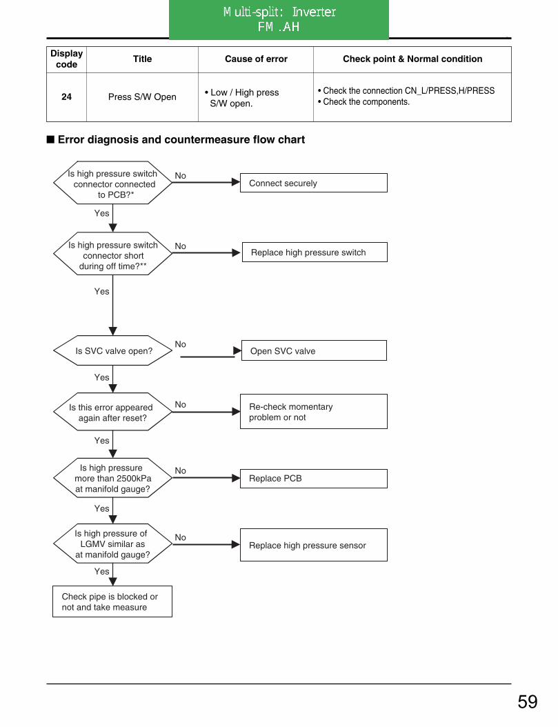
24 Press S/W Open • Low / High pressS/W open.
• Check the connection CN_L/PRESS,H/PRESS• Check the components.
Displaycode
Title Cause of error Check point & Normal condition
Is high pressure switch connector connected
to PCB?*
No Connect securely
Is high pressure switch connector short
during off time?**
Yes
No
Is this error appeared again after reset?
Yes
No
Is SVC valve open?
Yes
Re-check momentary problem or not
Open SVC valveNo
Yes
Replace high pressure switch
Is high pressure more than 2500kPaat manifold gauge?
No Replace PCB
Yes
Is high pressure of LGMV similar as
at manifold gauge?
No Replace high pressure sensor
Yes
Check pipe is blocked ornot and take measure
Error diagnosis and countermeasure flow chart
59
4. Trouble Shooting
- 82 -Copyright ©2007 LG Electronics. Inc. All right reserved.Only for training and service purposes LGE Internal Use Only
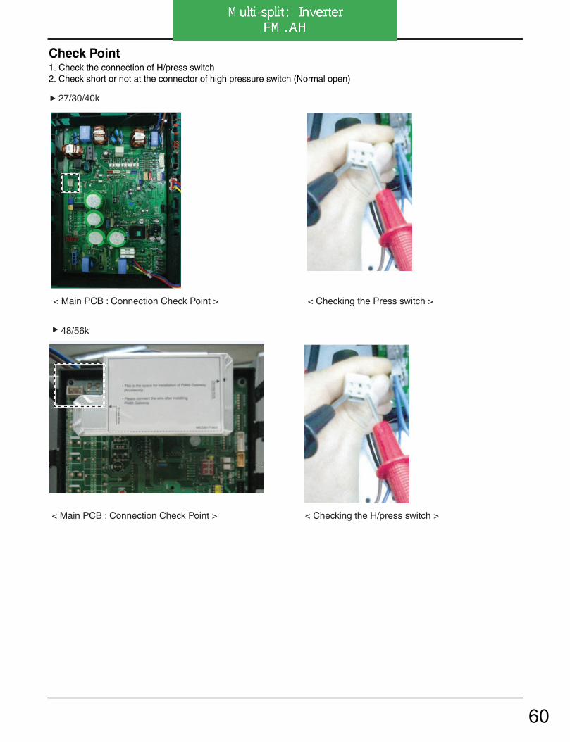
Check Point1. Check the connection of H/press switch2. Check short or not at the connector of high pressure switch (Normal open)
< Main PCB : Connection Check Point > < Checking the Press switch >
< Main PCB : Connection Check Point > < Checking the H/press switch >
27/30/40k
48/56k
60

4. Trouble Shooting
- 112 -Copyright ©2007 LG Electronics. Inc. All right reserved.Only for training and service purposes LGE Internal Use Only
25 Input voltageAbnomal Input Voltage (R,S,T -N /140Vac↓ ,300Vac ↑ )
Check the power source.• Check the components.
Displaycode Title Cause of error Check point & Normal condition
Tester
<INVERTER PCB>
INPUT VOLINPUT VOLTAGE INV AGE INV
<INPUT VOLTAGE Check Point>
GND GND
INPUT VOLTAGE INV
GND < CH25 Check Point >
Error Diagnosis and Countermeasure Flow Chart
Yes
Recheck power and installation condition
Yes
Is Inverter PCB Normal?No
Replace inverter PCB assembly
Is input voltage normal? No R~S/S~T/T~R phase voltage is 400V ±10%R~N/S~N/T~N phase voltage is 220V ±10% Check connection condition and wiring if power is abnormal.
61

4. Trouble Shooting
- 83 -Copyright ©2007 LG Electronics. Inc. All right reserved.Only for training and service purposes LGE Internal Use Only
Check Point1. Check the Input Voltage (L–N 220V±10%)
2. Check Input Voltage Sensor output voltage (2.5Vdc±10%)
25 Input voltage • Abnormal Input voltage(140Vac , 300Vac)
• Check the power source.• Check the components.
Displaycode
Title Cause of error Check point & Normal condition
Is Inverter PCB Normal? No
Replace inverter PCB assembly
Is input voltage normal ? No
Check L~N Voltage is 220V±15%
Yes
< Input Power Source Check Point >
Recheck power and installation condition
Yes
Error Diagnosis and Countermeasure Flow Chart
62

4. Trouble Shooting
- 84 -Copyright ©2007 LG Electronics. Inc. All right reserved.Only for training and service purposes LGE Internal Use Only
< Inverter PCB> < Input Voltage Sensing Check Point >
GND GND
INPUT(V) INPUT(V) INPUT(V)
< Inverter PCB> < Input Voltage Sensing Check Point >
FM27AH t/m FM57AH
FM49AH t/m FM57AH
Vdc
Vdc
GND
63
4. Trouble Shooting
- 85 -Copyright ©2007 LG Electronics. Inc. All right reserved.Only for training and service purposes LGE Internal Use Only
26 DC CompressorPosition
• Compressor Starting fail error
• Check the connection of comp wire “U,V,W”• Malfunction of compressor• Check the component of “IPM”, detection parts.
Displaycode
Title Cause of error Check point & Normal condition
Error Diagnosis and Countermeasure Flow Chart
Is installation condition normal?
No
Yes
Yes
Recheck power and installation condition
1. Check Pipe clogging/distortion2. Check Covering (Indoor/Outdoor Unit)3. Check EEV connector assemble condition/normal operation4. Check refrigerant pressure Reassemble or manage if abnormality found
1. Check resistance between each terminal of compressor (0.188 ±7%)2. Check insulation resistance between compressor terminal and pipe (over 50MΩ ) Replace compressor if abnormality found
Are the resistance Between each phase and
insulation resistance of Inverter compressor normal?
No
Yes
1. Check inverter PCB assembly U,V,W connector connection condition2. Check wire disconnection and wiring3. Check compressor terminal connection condition (bad contact) Reassemble if abnormality found
Is compressor Wire connection condition normal?
No
Yes
Check inverter PCB assembly IPM normality Replace inverter PCB assemblyIs inverter PCB assembly normal?
No
64

4. Trouble Shooting
- 113 -Copyright ©2007 LG Electronics. Inc. All right reserved.Only for training and service purposes LGE Internal Use Only
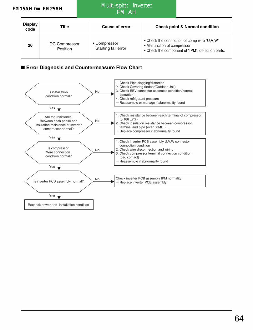
26 DC CompressorPosition
• Compressor Starting fail error
• Check the connection of comp wire “U,V,W”• Malfunction of compressor• Check the component of “IPM”, detection parts.
Displaycode
Title Cause of error Check point & Normal condition
Check Point1. Check the connection condition of PCB.
2. Check the connection condition of Comp. U,V,W wire.
3. Check the comp resistor and insulation resistance .
4. Check the IPM.(Refer 106 page)
5. Check the pressure of refrigerant.
6. Check the Service Valve Open.
UUV UV UV UV UW VW VW VW VWWWWWWWW VVVVWWWWW V UW V UUUVVVVWWWWW VW VW V U
Is installation condition normal?
No
Yes
Yes
Recheck power and installation condition
1. Check Pipe clogging/distortion2. Check Covering (Indoor/Outdoor Unit)3. Check EEV connector assemble condition/normal operation4. Check refrigerant pressure Reassemble or manage if abnormality found
1. Check resistance between each terminal of compressor (1.083~1.123Ω ±5%) 2. Check insulation resistance between compressor terminal and pipe (over 50M ) Replace compressor if abnormality found
Are the resistance Between each phase and
insulation resistance of Inverter compressor normal?
No
Yes
1. Check inverter PCB assembly U,V,W connector connection condition2. Check wire disconnection and wiring3. Check compressor terminal connection condition (bad contact) Reassemble if abnormality found
Is compressor Wire connection condition normal?
No
Yes
Check inverter PCB assembly IPM normality Replace inverter PCB assemblyIs inverter PCB assembly normal?
No
Error Diagnosis and Countermeasure Flow Chart
65

4. Trouble Shooting
- 86 -Copyright ©2007 LG Electronics. Inc. All right reserved.Only for training and service purposes LGE Internal Use Only
27 AC Input Instant overCurrent Error
Inverter PCB input current is over100A(peak)for 2us
1. Overload operation (Pipe clogging/Covering/EEVdefect/Ref. overcharge)
2. Compressor damage (Insulation damage/Motordamage)
3. Input voltage abnormal (L,N)4. Power line assemble condition abnormal5. Inverter PCB assembly Damage (input current
sensing part)
Displaycode
Title Cause of error Check point & Normal condition
※ PFCM Moudle checking method
① Set the multi tester to diode mode.
② Check short between input signal pin which areplaced below PFC Module
③ Replace PCB assembly if it is short between pinsexcept No.4,5 pins.
CAUTIONPFCM module No.4,5 pins are internal short state.
Error Diagnosis and Countermeasure Flow Chart
No
1.Check Pipe clogging/distortion2.Check Covering (Indoor/Outdoor Unit)3.Check EEV connector assemble condition/normal operation4.Check refrigerant pressure Reassemble or manage if abnormality found
Is installation condition normal?
Is compressor Wire connection condition normal?
1.Check inverter PCB assembly U,V,W connector connection condition2.Check wire disconnection and wiring3.Check compressor terminal connection condition(bad contact) Reassemble if abnormality found
Is AC input Wire connectioncondition normal?
1.Check L,N connection condition2.Check wire disconnection and wiring Reassemble if abnormality found
Is inverter PCB assemblynormal?
Yes
No
Recheck power and installation condition
Yes
Yes
Yes
No
No
Yes
No Check L~N phase voltage is 220V ±15% Check connection condition and wiring if power is abnormal
Is input voltage normal?
Check inverter PCB assembly PFCM normality Replace inverter PCB assembly
Signal pinSignal pinSignal pin
1188
66
4. Trouble Shooting
- 87 -Copyright ©2007 LG Electronics. Inc. All right reserved.Only for training and service purposes LGE Internal Use Only
Error Diagnosis and Countermeasure Flow Chart
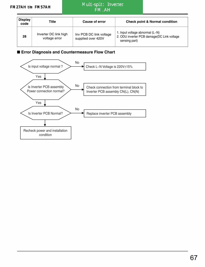
28Inverter DC link high
voltage errorInv PCB DC link voltagesupplied over 420V
1. Input voltage abnormal (L~N)2. ODU inverter PCB damage(DC Link voltage
sensing part)
Displaycode
Title Cause of error Check point & Normal condition
Is Inverter PCB assemblyPower connection normal?
Check connection from terminal block toInverter PCB assembly CN(L), CN(N)
Yes
Is input voltage normal ? No
No
Yes
Is Inverter PCB Normal?No
Replace inverter PCB assembly
Recheck power and installationcondition
Check L~N Voltage is 220V±15%
67
4. Trouble Shooting
- 88 -Copyright ©2007 LG Electronics. Inc. All right reserved.Only for training and service purposes LGE Internal Use Only
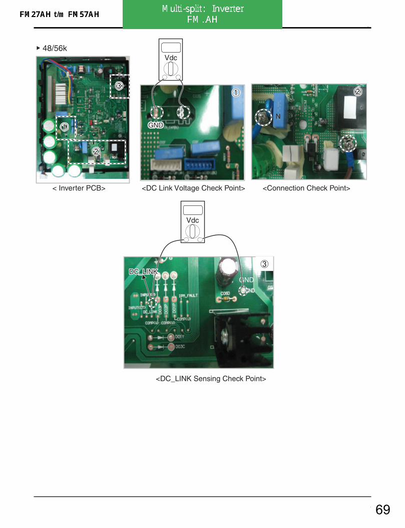
Check Point1. Check the CN_(L),CN_(N) Connection condition at the Inverter PCB.(Refer to outdoor wiring diagram)
2. Check the DC Link voltage at not operating(280V↑ )
3. Check the DC Link voltage at Comp operating(340V↑ )
4. Check DC Link Sensing Signal : 2.4~2.8V (Refer the Picture)
Vdc
< Main PCB>
<DC Link Voltage Check Point> <DC_LINK Sensing Check Point>
< Input Power Source Check Point >
27/30/40k
Vdc
68
4. Trouble Shooting
- 89 -Copyright ©2007 LG Electronics. Inc. All right reserved.Only for training and service purposes LGE Internal Use Only
Vdc
Vdc
< Inverter PCB>
<DC Link Voltage Check Point> <Connection Check Point>
GNDGND GND
GND
<DC_LINK Sensing Check Point>
N N
48/56k
LL
DC_LINKDC_LINK DC_LINK
69

4. Trouble Shooting
- 90 -Copyright ©2007 LG Electronics. Inc. All right reserved.Only for training and service purposes LGE Internal Use Only
29Inverter compressor over
currentInverter compressor inputcurrent is over 30A
1. Overload operation (Pipe clogging/Covering/EEV defect/Ref. over-charge)
2. Compressor damage(Insulation damage/Motordamage)
3. Input voltage low4. ODU inverter PCB assembly damage
Displaycode
Title Cause of error Check point & Normal condition
Error Diagnosis and Countermeasure Flow Chart
Is installation condition normal?
No
Yes
Yes
Yes
Recheck power and installation condition
1. Check Pipe clogging/distortion2. Check Covering (Indoor/Outdoor Unit)3. Check EEV connector assemble condition/normal operation4. Check refrigerant pressure Reassemble or manage if abnormality found
Yes
Is input voltage normal?No Check
L~N phase is 220V ±15% Check connection condition and wiring if power is abnormal
Yes
Is inverter PCB assembly normal?
No Check inverter PCB assembly IPM normality Replace inverter PCB assembly
Are the resistance Between each phase and
insulation resistance of Inverter compressor normal?
No
1. Check resistance between each terminal of compressor (0.188 ±7%)2. Check insulation resistance between compressor terminal and pipe (over 50MΩ ) Replace compressor if abnormality found
Is compressor Wire connection condition normal?
No
1. Check inverter PCB assembly U,V,W connector connection condition2. Check wire disconnection and wiring3. Check compressor terminal connection condition (bad contact) Reassemble if abnormality found
70

- 68 -Copyright ©2007 LG Electronics. Inc. All right reserved.Only for training and service purposes LGE Internal Use Only
4. Trouble Shooting
LEV Openness(Pulse)
COMP Frequency(Hz)
Toff(105) °C
T1(90) °C
T2(95) °C
OFFNormal
OFF ControlNormal
Normal
Normal
D-Pipe temp.
32
33
D-pipe (Inverter)temp. high(105°C↑ )
D-pipe (Constant)temp. high(105°C↑ )
• Discharge sensor(Inverter) temp. high
• Discharge sensor(Cons.) temp. high
• Check the discharge pipe sensor for INV.• Check the install condition for over load.• Check the leakage of refrigerant.• Check the SVC V/V open.
• Check the discharge pipe sensor for Cons.• Check the install condition for over load.• Check the leakage of refrigerant.• Check the SVC V/V open.
Displaycode
Title Cause of error Check point & Normal condition
Check Point• CH 32
1. Check the install condition for over load.
2. Check the SVC V/V open.
3. Check the leakage of refrigerant.
• CH 33
1. Check the install condition for over load.
2. Check the SVC V/V open.
3. Check the leakage of refrigerant.
4. Check the constant compressor. (same with CH21)
71
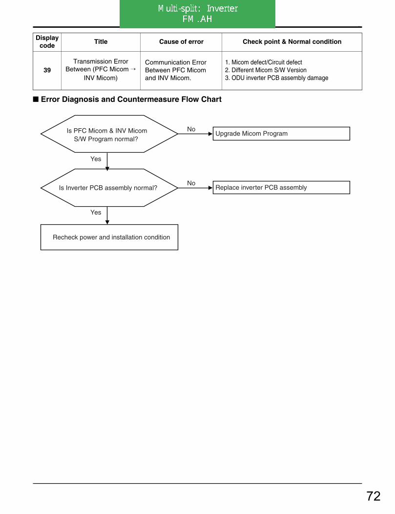
4. Trouble Shooting
- 115 -Copyright ©2007 LG Electronics. Inc. All right reserved.Only for training and service purposes LGE Internal Use Only
39Transmission Error
Between (PFC Micom INV Micom)
Communication ErrorBetween PFC Micomand INV Micom.
1. Micom defect/Circuit defect2. Different Micom S/W Version3. ODU inverter PCB assembly damage
Displaycode
Title Cause of error Check point & Normal condition
Error Diagnosis and Countermeasure Flow Chart
Is Inverter PCB assembly normal? No
Replace inverter PCB assembly
Is PFC Micom & INV Micom S/W Program normal?
No Upgrade Micom Program
Yes
Yes
Recheck power and installation condition
72

4. Trouble Shooting
- 116 -Copyright ©2007 LG Electronics. Inc. All right reserved.Only for training and service purposes LGE Internal Use Only
40C/T
Sensor Error • Initial current error
• Malfunction of current detection circuit.(Open / Short)
• The voltage of "C01N" Is 4.0Vdc(25A) .• Check CT Sensor output voltage : 2.5Vdc
±5%
Displaycode
Title Cause of error Check point & Normal condition
Tester
CT Sensor Output(at the INVERTER PCB)
<INVERTER PCB> INPUTINPUT VOLVOLTAGE INV AGE INV
GND GND
COMPCOMP CURRENT CURRENT U,VU,V,W ,W
<INPUT VOLTAGE Check Point>
INPUTVOLTAGE INV
GND
COMP CURRENTU,V,W
Error Diagnosis and Countermeasure Flow Chart
No Check the input voltage source(Is nomal the offset of R-N,T-N voltage)
Is CT Sensor Output is right?No If the CT Sensor output is not 2.5Vdc°æ5%
Replace the Inverter PCB
Yes
Yes
Recheck the Inverter PCB and installation condition
Is input voltage normal?
73

4. Trouble Shooting
- 91 -Copyright ©2007 LG Electronics. Inc. All right reserved.Only for training and service purposes LGE Internal Use Only
Check Point1. Check the Input Voltage (L–N 220V±10%)
2. Check Input Voltage Sensor output voltage (2.5Vdc±10%)
Is Inverter PCB Normal? No
Replace inverter PCB assembly
Is input voltage normal ? No
Check L~N Voltage is 220V±15%
Yes
< Input Power Source Check Point >
Recheck power and installation condition
Yes
Error Diagnosis and Countermeasure Flow Chart
40C/T
Sensor Error • Initial current error
• Malfunction of current detection circuit.(Open / Short)
• Check CT Sensor output voltage : 2.5Vdc ±5%
Displaycode
Title Cause of error Check point & Normal condition
74

4. Trouble Shooting
- 92 -Copyright ©2007 LG Electronics. Inc. All right reserved.Only for training and service purposes LGE Internal Use Only
< Inverter PCB> < CT Sensing Check Point >
GND GND
INPUT(CT) INPUT(CT) INPUT(CT)
< Inverter PCB> < CT Sensing Check Point >
1 2 3
FM27AH t/m FM41AH
FM49AH t/m FM57AH
Vdc
Vdc
GND
75
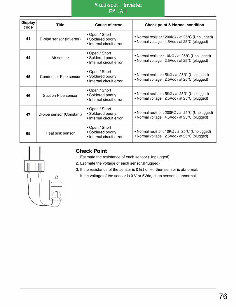
- 69 -Copyright ©2007 LG Electronics. Inc. All right reserved.Only for training and service purposes LGE Internal Use Only
4. Trouble Shooting
Ω
41
44
45
46
47
65
D-pipe sensor (Inverter)
Air sensor
Condenser Pipe sensor
Suction Pipe sensor
D-pipe sensor (Constant)
Heat sink sensor
• Open / Short• Soldered poorly• Internal circuit error
• Open / Short• Soldered poorly• Internal circuit error
• Open / Short• Soldered poorly• Internal circuit error
• Open / Short• Soldered poorly• Internal circuit error
• Open / Short• Soldered poorly• Internal circuit error
• Open / Short• Soldered poorly• Internal circuit error
• Normal resistor : 200KΩ / at 25°C (Unplugged)• Normal voltage : 4.5Vdc / at 25°C (plugged)
• Normal resistor : 10KΩ / at 25°C (Unplugged)• Normal voltage : 2.5Vdc / at 25°C (plugged)
• Normal resistor : 5KΩ / at 25°C (Unplugged)• Normal voltage : 2.5Vdc / at 25°C (plugged)
• Normal resistor : 5KΩ / at 25°C (Unplugged)• Normal voltage : 2.5Vdc / at 25°C (plugged)
• Normal resistor : 200KΩ / at 25°C (Unplugged)• Normal voltage : 4.5Vdc / at 25°C (plugged)
• Normal resistor : 10KΩ / at 25°C (Unplugged)• Normal voltage : 2.5Vdc / at 25°C (plugged)
Displaycode
Title Cause of error Check point & Normal condition
Check Point1. Estimate the resistance of each sensor.(Unplugged)
2. Estimate the voltage of each sensor.(Plugged)
3. If the resistance of the sensor is 0 kΩ or ∞, then sensor is abnormal.
If the voltage of the sensor is 0 V or 5Vdc, then sensor is abnormal.
76

- 70 -Copyright ©2007 LG Electronics. Inc. All right reserved.Only for training and service purposes LGE Internal Use Only
4. Trouble Shooting
51
60
Over capacity
EEPROMCheck sum
• Over capacityCombination
• Check sum error
• Check the indoor unit capacity.• Check the combination table.
• Check the PCB ASM P/No.• Check the poor soldering.
Displaycode
Title Cause of error Check point & Normal condition
Check Point• CH 51
1. Check the indoor unit capacity.
• CH 60
1. Check the insertion condition of EEPROM.
2. Check the poor soldering
Model Gross max. capacity Max. single indoor unit capacity
A2UW146FA3 21k
A2UW166FA0
A2UW166FA1 24k 12k
A3UW186FA0
A3UW216FA333k
A4UW246FA3 18k
77
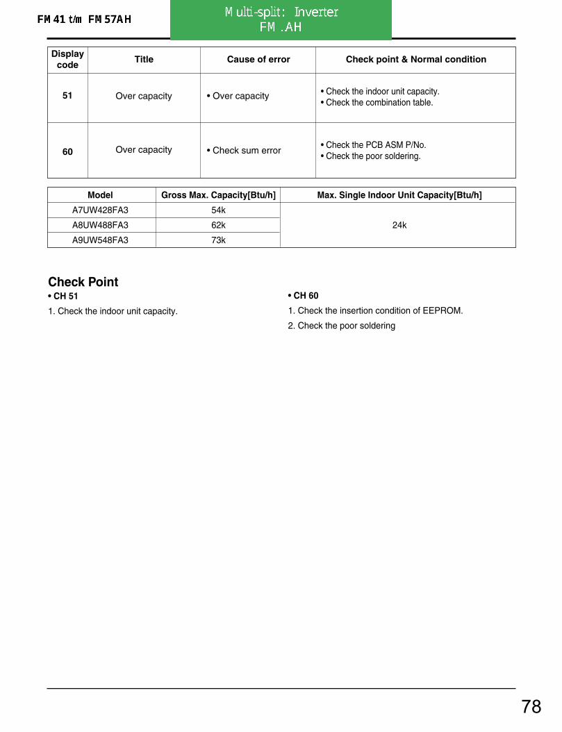
4. Trouble Shooting
- 118 -Copyright ©2007 LG Electronics. Inc. All right reserved.Only for training and service purposes LGE Internal Use Only
51
60
Over capacity
Over capacity
• Over capacity
• Check sum error
• Check the indoor unit capacity.• Check the combination table.
• Check the PCB ASM P/No.• Check the poor soldering.
Displaycode
Title Cause of error Check point & Normal condition
Check Point• CH 51
1. Check the indoor unit capacity.
• CH 60
1. Check the insertion condition of EEPROM.
2. Check the poor soldering
Model Gross Max. Capacity[Btu/h] Max. Single Indoor Unit Capacity[Btu/h]
A7UW428FA3 54k
A8UW488FA3 62k 24k
A9UW548FA3 73k
78

4. Trouble Shooting
- 93 -Copyright ©2007 LG Electronics. Inc. All right reserved.Only for training and service purposes LGE Internal Use Only
52Transmission error
between (Inverter PCB Main PCB)
Main controller of Masterunit of Master unit can’treceive signal frominverter controller
1. Power cable or transmission cable is not connected
2. Defect of outdoor Main fuse/Noise Filter3. Defect of outdoor Main / inverter PCB
Displaycode
Title Cause of error Check point & Normal condition
Error diagnosis and countermeasure flow chart
Is transmission LED (Yellow) of inverter
compressor PCB on?
Yes
No Is noise filter or fusenormal?
Replace noise filter or fuseNo
Replace inverter compressor PCB
Is transmission cableconnected correctly?
Yes
NoRe-connect transmission cable
Is MAIN PCB normal?
Yes
NoReplace MAIN PCB
Replace inverter compressor PCB
Yes
Check Point- Check the Transmission connector and LED (Main & Inverter)
<MAIN PCB> <Inverter PCB>
48/56k
79
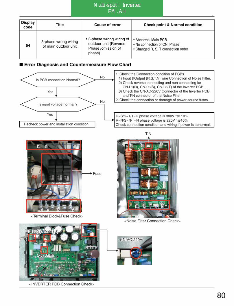
4. Trouble Shooting
- 119 -Copyright ©2007 LG Electronics. Inc. All right reserved.Only for training and service purposes LGE Internal Use Only
543-phase wrong wiringof main outdoor unit
• 3-phase wrong wiring ofoutdoor unit (ReversePhase /omission ofphase)
• Abnormal Main PCB• No connection of CN_Phase• Changed R, S, T connection order
Displaycode
Title Cause of error Check point & Normal condition
<INVERTER PCB Connection Check>
<Terminal Block&Fuse Check> <Noise Filter Connection Check>
CN-AC-220V CN-AC-220V CN-AC-220V
CN-L1(R) CN-L1(R)
CN-L2(S) CN-L2(S)
CN-L3(T) CN-L3(T) CN-L1(R)
CN-L2(S)
CN-L3(T)
R S R S T N G N G
Fuse
R S R S T N N R S T N
R S R S T N N R S T N
T-N
R S T
R S T N G
Error Diagnosis and Countermeasure Flow Chart
No
R~S/S~T/T~R phase voltage is 380V °æ 10%R~N/S~N/T~N phase voltage is 220V °æ10%Check connection condition and wiring if power is abnormal.
Is PCB connection Normal?No
1. Check the Connection condition of PCBs 1) Input &Output (R,S,T,N) wire Connection of Noise Filter. 2) Check reverse connecting and non connecting for CN-L1(R), CN-L2(S), CN-L3(T) of the Inverter PCB 3) Check the CN-AC-220V Connector of the Inverter PCB and T-N connector of the Noise Filter2. Check the connection or damage of power source fuses.
Yes
Yes
Recheck power and installation condition
Is input voltage normal ?
80
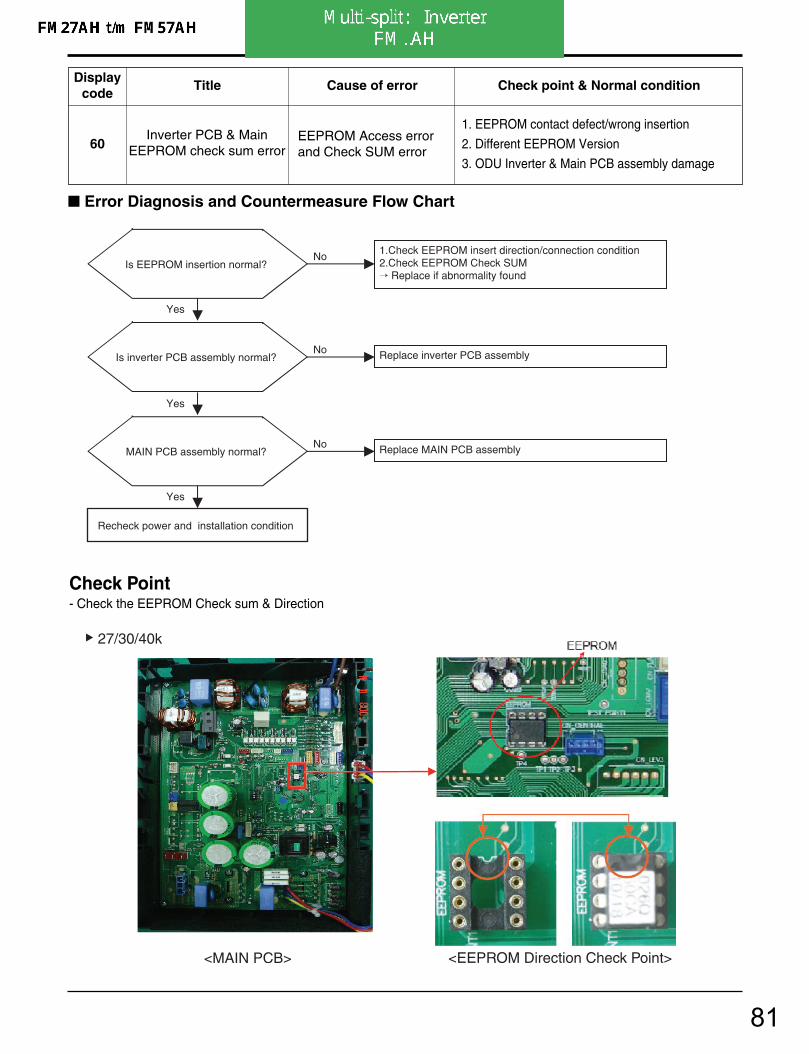
4. Trouble Shooting
- 94 -Copyright ©2007 LG Electronics. Inc. All right reserved.Only for training and service purposes LGE Internal Use Only
60Inverter PCB & Main
EEPROM check sum errorEEPROM Access errorand Check SUM error
1. EEPROM contact defect/wrong insertion
2. Different EEPROM Version
3. ODU Inverter & Main PCB assembly damage
Displaycode
Title Cause of error Check point & Normal condition
Error Diagnosis and Countermeasure Flow Chart
Is EEPROM insertion normal?No
Yes
Recheck power and installation condition
1.Check EEPROM insert direction/connection condition2.Check EEPROM Check SUM Replace if abnormality found
Is inverter PCB assembly normal?No
Yes
Replace inverter PCB assembly
Yes
MAIN PCB assembly normal?No Replace MAIN PCB assembly
Check Point- Check the EEPROM Check sum & Direction
<MAIN PCB> <EEPROM Direction Check Point>
27/30/40k
81
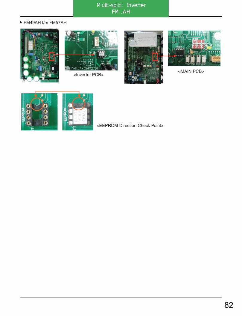
4. Trouble Shooting
- 95 -Copyright ©2007 LG Electronics. Inc. All right reserved.Only for training and service purposes LGE Internal Use Only
<MAIN PCB> <Inverter PCB>
<EEPROM Direction Check Point>
FM49AH t/m FM57AH
82
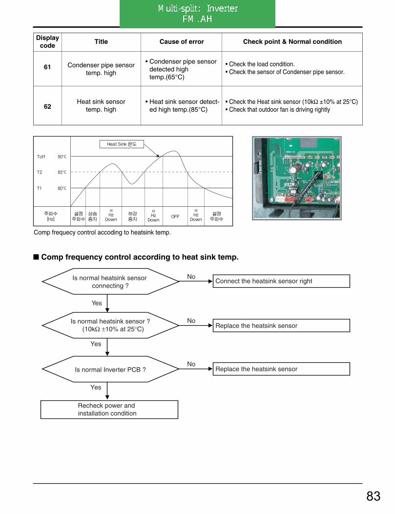
4. Trouble Shooting
- 120 -Copyright ©2007 LG Electronics. Inc. All right reserved.Only for training and service purposes LGE Internal Use Only
61
62
Condenser pipe sensortemp. high
Heat sink sensortemp. high
• Condenser pipe sensordetected hightemp.(65°C)
• Heat sink sensor detect-ed high temp.(85°C)
• Check the load condition.• Check the sensor of Condenser pipe sensor.
• Check the Heat sink sensor (10kΩ ±10% at 25°C)• Check that outdoor fan is driving rightly
Displaycode
Title Cause of error Check point & Normal condition
Comp frequecy control accoding to heatsink temp.
α α α
°C
°C
°C
Comp frequency control according to heat sink temp.
No
Is normal heatsink sensor connecting ?
No Connect the heatsink sensor right
Replace the heatsink sensor
No Replace the heatsink sensor
Yes
Yes
Recheck power and installation condition
Is normal heatsink sensor ? (10kΩ ±10% at 25°C)
Yes
Is normal Inverter PCB ?
83
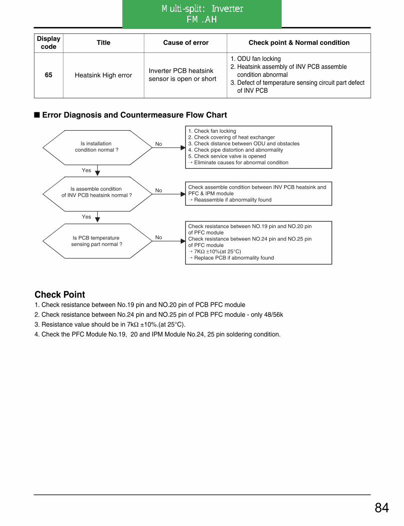
4. Trouble Shooting
- 98 -Copyright ©2007 LG Electronics. Inc. All right reserved.Only for training and service purposes LGE Internal Use Only
65 Heatsink High errorInverter PCB heatsinksensor is open or short
1. ODU fan locking2. Heatsink assembly of INV PCB assemble
condition abnormal3. Defect of temperature sensing circuit part defect
of INV PCB
Displaycode
Title Cause of error Check point & Normal condition
Is installation condition normal ?
No
Yes
1. Check fan locking2. Check covering of heat exchanger3. Check distance between ODU and obstacles4. Check pipe distortion and abnormality5. Check service valve is opened Eliminate causes for abnormal condition
Check resistance between NO.19 pin and NO.20 pin of PFC module Check resistance between NO.24 pin and NO.25 pin of PFC module 7KΩ ±10%(at 25°C) Replace PCB if abnormality found
Is assemble condition of INV PCB heatsink normal ?
Is PCB temperature sensing part normal ?
No
No
Yes
Check assemble condition between INV PCB heatsink andPFC & IPM module Reassemble if abnormality found
Error Diagnosis and Countermeasure Flow Chart
Check Point1. Check resistance between No.19 pin and NO.20 pin of PCB PFC module
2. Check resistance between No.24 pin and NO.25 pin of PCB PFC module - only 48/56k
3. Resistance value should be in 7kΩ ±10%.(at 25°C).
4. Check the PFC Module No.19, 20 and IPM Module No.24, 25 pin soldering condition.
84
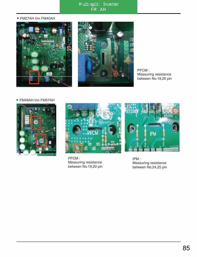
4. Trouble Shooting
- 99 -Copyright ©2007 LG Electronics. Inc. All right reserved.Only for training and service purposes LGE Internal Use Only
PFCM : Measuring resistance between No.19,20 pin
IPM : Measuring resistance between No.24,25 pin
PFCM : Measuring resistance between No.19,20 pin
FM27AH t/m FM40AH
FM49AH t/m FM57AH
85

4. Trouble Shooting
- 121 -Copyright ©2007 LG Electronics. Inc. All right reserved.Only for training and service purposes LGE Internal Use Only
67Outdoor fan
lock• Outdoor fan is not oper-
ating
• Check the fan condition.• Check the fan connector• Check the fan control part of the INVERTER PCB
Displaycode
Title Cause of error Check point & Normal condition
Error Diagnosis and Countermeasure Flow Chart
<FAN Motor Connection check>
Replace inverter PCB assembly
Is Fan motor nomal? No
Change abnomal motor
Yes
Is fan connector condition right ? No
Do right fan connector condition
Yes
CH67(Outdoor fan lock) occurrence
<INVERTER PCB connection>
<fan motor middle connection>
86

4. Trouble Shooting
- 100 -Copyright ©2007 LG Electronics. Inc. All right reserved.Only for training and service purposes LGE Internal Use Only
67 Fan Lock Error
Fan RPM is 10RPM orless for 5 sec. when ODUfan starts or 40 RPM orless after fan starting.
1. ODU fan locking2. Heatsink assembly of INV PCB assemble condi-
tion abnormal3. Defect of temperature sensing circuit part defect
of INV PCB
Displaycode
Title Cause of error Check point & Normal condition
Is ODU Fan Motor Assemble condition normal?
No
Yes
Recheck power and installation condition
Check ODU Fan Motor assemble condition and fan locking Reassemble or replace if abnormality found
Is ODU Fan Motor normal?No
Yes
1. Set the multi tester to diode mode.2. Check voltage between 1pin and 4pin of Fan Motor (1±0.2V)3. Replace Inverter PCB if abnormality found.
Is wire connection of ODU Fan Motor wire normal?
No
Yes
Check wiring between OUD fan motor and Inverter PCB( Check if Hall Senor and Motor output terminal color is matched) Reassemble if abnormality found
Is Inverter PCB assembly normal?No
Yes
Replace Inverter PCB assembly
Error Diagnosis and Countermeasure Flow Chart
Check Point1. Check voltage between 1pin and 4pin of Fan Mortor connector (Tester diode mode)
2. Voltage vaule should be in 1V ±0.2V.
87

4. Trouble Shooting
- 101 -Copyright ©2007 LG Electronics. Inc. All right reserved.Only for training and service purposes LGE Internal Use Only
Tester
Fan motorconnector
Check voltage betwen1pin and 4pin of fan motor
<Inverter PCB>
<Main PCB>
FM49AH t/m FM57AH
FM27AH t/m FM41AH
88

4. Trouble Shooting
- 102 -Copyright ©2007 LG Electronics. Inc. All right reserved.Only for training and service purposes LGE Internal Use Only
73AC input instant over cur-
rent error (Matter of software)
Inverter PCB input powercurrent is over 48A(peak)for 2ms
1. Overload operation (Pipe clogging/Covering/EEVdefect/Ref.overcharge)
2. Compressor damage (Insulation damage/Motor damage)
3. Input voltage abnormal (L, N)4. Power line assemble condition abnormal5. Inverter PCB assembly damage
(input current sensing part)
Displaycode
Title Cause of error Check point & Normal condition
Error Diagnosis and Countermeasure Flow Chart
No
1.Check Pipe clogging/distortion2.Check Covering (Indoor/Outdoor Unit)3.Check EEV connector assemble condition/normal operation4.Check refrigerant pressure Reassemble or manage if abnormality found
Is installation condition normal?
Is compressor Wire connection condition normal?
1.Check inverter PCB assembly U,V,W connector connection condition2.Check wire disconnection and wiring3.Check compressor terminal connection condition(bad contact) Reassemble if abnormality found
Is AC input Wire connectioncondition normal?
1.Check L,N connection condition2.Check wire disconnection and wiring Reassemble if abnormality found
Is inverter PCB assemblynormal?
Yes
No
Recheck power and installation condition
Yes
Yes
Yes
No
No
Yes
No Check L~N phase voltage is 220V ± 10% Check connection condition and wiring if power is abnormal
Is input voltage normal?
Check inverter PCB assembly IPM normality Replace inverter PCB assembly
89
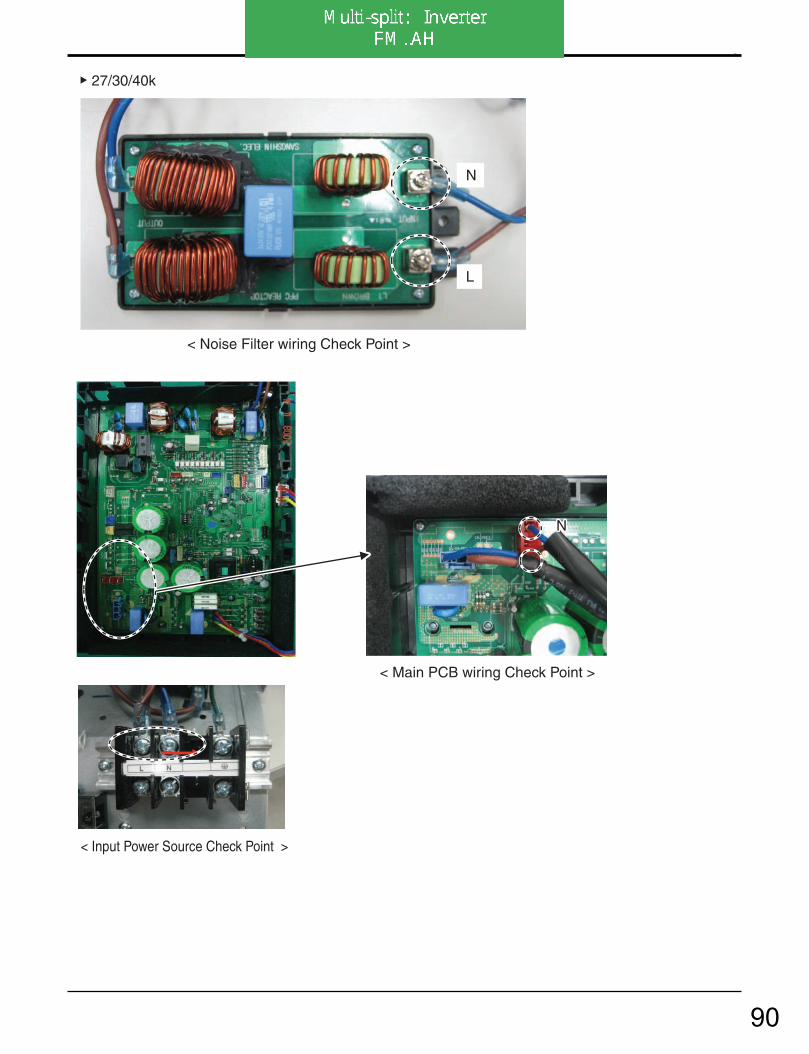
4. Trouble Shooting
- 103 -Copyright ©2007 LG Electronics. Inc. All right reserved.Only for training and service purposes LGE Internal Use Only
< Input Power Source Check Point >
< Main PCB wiring Check Point >
NN
L
N
L
N
L
27/30/40k
< Noise Filter wiring Check Point >
90

4. Trouble Shooting
- 104 -Copyright ©2007 LG Electronics. Inc. All right reserved.Only for training and service purposes LGE Internal Use Only
< Noise Filter wiring Check Point >
< Input Power Source Check Point >
N L
L
N
< Inverter PCB wiring Check Point >
L N
48/56k
91

Multi-split Variabel (aan/uit)
M..AC/AH
LG
92

Functions
Error Indicator• The function is to self-diagnoisis airconditioner and express the troubles identifically if there is any trouble.• Error mark is ON/OFF for the operation LED of evaporator body in the same manner as the following table.• If more than two troubles occur simultaneously, primarily the highest trouble fo error code is expressed.• After error occurrence, if error is released, error LED is also released simultaneously.• To operate again on the occurrence of error code, be sure to turn off the power and then turn on.• Having or not of error code is different from Model.
ErrorCode
Error LED(Indoor body operation LED) Error contents SVC check point
1(once)
3sec 3sec 3sec
5sec• Indoor air temperature thermistor
open/short.• Indoor air TH ass'y check
9(9times)
3sec
• Indoor EEP ROM data (Art type only)
2(twice)
3sec 3sec
• Indoor inlet pipe TH ass'y check
• Indoor inlet pipe temperature thermistor open/short.
5(5times)
3sec
(6times)
3sec
• Communication line/circuit • Poor communication
6 • Indoor outlet pipe TH ass'y check
• Indoor outlet pipe temperature thermistor open/shor
7 • Operate indoor units only heating or cooling mode.
• Defferent Operation (Simultanueous operation of cooling and heating.
44 • Outdoor air TH ass'y check
• Replace main PCB DC ASM
• Outdoor air temperature thermistor open/short
45 • Outdoor pipe TH ass'y check• Outdoor pipe themperature thermistor open/short
51 • Indoor unit combination check (Refer to Max. capacity)• Overload combination
(7times)
3sec
3sec 3sec
3sec
3sec 3sec
: ten digits: one digits
Self-diagnosis Function
Signal Receptor
Signalreceptor
Operation indication lamps
Operation indication lamps
Receives the signals from the remote controller.(Signal receiving sound: two short beeps or one long beep.)Operation Indication Lamps
Sleep Mode
Timer
Defrost Mode
Outdoor unit operation
PLASMA
Receives the signals from the remote controller.(Signal receiving sound: two short beeps or one long beep.)Operation Indication Lamps
On/Off
Sleep Mode
Timer
Defrost Mode
OUTDOOR
OUTDOOR UNITOPERATION
On/Off
: Lights up during the system operation.: Lights up during Sleep Mode Auto operation.: Lights up during Timer operation.: Lights up during Defrost Mode or Hot Start operation (Heat pump model only) : Lights up during outdoor unit operation. (Cooling model only)
: Lights up during the system operation.: Lights up during Sleep Mode Auto operation.: Lights up during Timer operation.: Lights up during Defrost Mode or Hot Start operation.(Heat pump model only): Lights up during outdoor unit operation.(Cooling model only): Indicate PLASMA purifier operation.
93

Multi-split Multi-split tot 2005 A2-C.. A3-C.. A2-H.. A3-H.. LM..
94

Display Function 1. Heating Model 2. Cooling Model
• Cooling, Soft Dry, Fan, Heating • Cooling, Soft Dry, Fan
• Sleep Mode • Sleep Mode
• Timer Mode • Timer Mode
• Hot-start, Defrost
Self-diagnosis Function Error Indicator
• The function is to self-diagnoisis airconditioner and express the troubles identifically if there is any trouble.• Error mark is ON/OFF for the operation LED of evaporator body in the same manner as the following table.• If more than two troubles occur simultaneously, primarily the highest trouble fo error code is expressed.• After error occurrence, if error is released, error LED is also released simultaneously.• To operate again on the occurrence of error code 12, be sure to pull out power cord and then re-insert.• Having or not of error code is different from Model.
Operation Indicator
Timer Indicator
Sleep Timer Indicator
Defrost Indicator
Operation Indicator
Timer Indicator
Sleep Timer Indicator
Compressor on Indicator OUTDOOR
1(once)
(once)
(twice)
(twice)
(5times)
(once) (twice)
(3times)
3sec 3sec
3sec
3sec 3sec
3sec
3sec 3sec 3sec
3sec
3sec
2
3
5
12
ErrorCode
Error LED(Indoor body operation LED) Error contents SVC check point
• Indoor suction temperature thermistor open/short.
• Indoor pipe temperature thermistor open/short.
• Indoor TH ass'y check
• Outdoor TH ass'y check
• Resetting of remocon operating mode
• Communication line/circuit check
• Primarily check refrigerant pressure
• Connecting pipe check• Connecting cable check
• Outdoor suction temperature thermistor open/short.
• Outdoor pipe temperature thermistor open/short.
• Abnormal operation of multi product. (Simultanueous operation of cooling and heating)
• Misconnection of connecting cables
• Poor communication
95

RAC Standaard wandunit (aan/uit & Inverter)
Art Cool Deluxe (aan/uit & Inverter) (hoge wand)
Art Cool Panel (aan/uit & Inverter)
LG
96

RAC Standaard wandunit (aan/uit)Alle typen/uitvoeringen o.a:
LS-J.. / LS-K.. / LS-L..S..ACL / S..AH / S..ACP / S..AHPG..AH
ART COOL Panel / Deluxe (aan/uit) LS-P.... .. A09/12/18AH*C07/09/12AH*
97
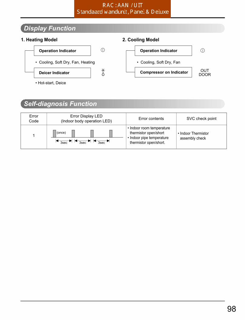
Self-diagnosis Function
Operation
Display Function 1. Heating Model 2. Cooling Model
• Cooling, Soft Dry, Fan, Heating • Cooling, Soft Dry, Fan
• Hot-start, Deice
Operation Indicator
Deicer Indicator
Operation Indicator
Compressor on Indicator OUTDOOR
3sec 3sec 3sec
(once)
ErrorCode
1
Error Display LED(Indoor body operation LED) Error contents
• Indoor room temperaturethermistor open/short
• Indoor pipe temperaturethermistor open/short.
• Indoor Thermistor assembly check
SVC check point
98

RAC Standaard wandunit Inverter
LS-N....LS-Q....LS-R.... S..ANS..AW
LG
99

Troubleshooting Guide
Self-diagnosis function
The cause of malfunction
Indoor TH. is short or open.
Temp. of Heat sink is over 95°C,or Heat sink TH. is shortor open.
Comunication error (serialcomunication).
DC peak error.
Running current is over-loaded.
Outdoor fan lock error(BLDC fan model)
The LED01M will be blinkingtwice.
The LED01M will be blinking 4times.
The LED01M will be blinking 5times.
The LED01M will be blinking 6times.
The LED01M will be blinking 7times.
The LED01M will be blinking 9times.
Keep operating state.
Restart compressor when heat sinkTemp. is 85°C below.
The operation is off(enable to restartby remote controller).
Compressor will be turned off immediately.(not enable to restart by remote controller)
Compressor will be turned off immediately.(not enable to restart by remote controller)
The operation is off(enable to restartby remote controller).
Malfunction indicator The operating stateErrorCode
1. The malfunction indicator of indoor (see the operating LED of the INDOOR)
The cause of malfunctionErrorCode
1 Indoor TH. is short or open.
Outdoor TH. is short or open.
Temp. of Heat sink is over 95°C./Heat sink TH. is short or open.
Comunication error (serialcomunication).
DC peak error.
Running current is over-loaded. (CT2)
D-PIPE TH is short or open.
The operating LED will be blink-ing once.
The operating LED will be blink-ing twice.
The operating LED will be blink-ing 4 times.
The operating LED will be blink-ing 5 times.
The operating LED will be blink-ing 6 times.
The operating LED will be blink-ing 7 times.
The operating LED will be blink-ing 10 times.
Keep operating state.
Keep operating state.
Restart compressor when Heat sinkTemp is 85°C below.
The operation is off(enable to restartby remote controller).
Compressor will be turned off immediately.(not enable to restart by remote controller)
Compressor will be turned off immediately.(not enable to restart by remote controller)
Compressor will be turned off immediately.(restart compressor when D-PIPE TH. isrecovred)
Malfunction indicator The operating state
2. The malfunction indicator of outdoor (see the LED01M on the outdoor PCB ass’y)
Error code ➅ , ➆ can’t be operated unless the power cord is removed.
2
4
5
6
7
2
4
5
6
7
9
D-PIPE TH is short or open. The LED01M will be blinking 10times.
Compressor will be turned off immediately.(restart compressor when D-PIPE TH. isrecovered)
10
10
Indoor fan lock error(BLDC fan model)
The operating LED will be blink-ing 8 times.
The operation is off(enable to restartby remote controller).8
Outdoor fan lock error(BLDC fan model)
The operating LED will be blink-ing 9 times.
The operation is off(enable to restartby remote controller).9
100
RAC ART COOL Deluxe Inverter C09AW*C12AW*
101

Troubleshooting Guide
Self-diagnosis function
The cause of malfunction
Indoor TH. is short or open.
Temp. of Heat sink is over 95°C,or Heat sink TH. is shortor open.
Comunication error (serialcomunication).
DC peak error.
Running current is over-loaded.
Outdoor fan lock error(BLDC fan model)
The LED01M will be blinkingtwice.
The LED01M will be blinking 4times.
The LED01M will be blinking 5times.
The LED01M will be blinking 6times.
The LED01M will be blinking 7times.
The LED01M will be blinking 9times.
Keep operating state.
Restart compressor when heat sinkTemp. is 85°C below.
The operation is off(enable to restartby remote controller).
Compressor will be turned off immediately.(not enable to restart by remote controller)
Compressor will be turned off immediately.(not enable to restart by remote controller)
The operation is off(enable to restartby remote controller).
Malfunction indicator The operating stateErrorCode
1. The malfunction indicator of indoor (see the operating LED of the INDOOR)
The cause of malfunctionErrorCode
1 Indoor TH. is short or open.
Outdoor TH. is short or open.
Temp. of Heat sink is over 95°C./Heat sink TH. is short or open.
Comunication error (serialcomunication).
DC peak error.
Running current is over-loaded. (CT2)
D-PIPE TH is short or open.
The operating LED will be blink-ing once.
The operating LED will be blink-ing twice.
The operating LED will be blink-ing 4 times.
The operating LED will be blink-ing 5 times.
The operating LED will be blink-ing 6 times.
The operating LED will be blink-ing 7 times.
The operating LED will be blink-ing 10 times.
Keep operating state.
Keep operating state.
Restart compressor when Heat sinkTemp is 85°C below.
The operation is off(enable to restartby remote controller).
Compressor will be turned off immediately.(not enable to restart by remote controller)
Compressor will be turned off immediately.(not enable to restart by remote controller)
Compressor will be turned off immediately.(restart compressor when D-PIPE TH. isrecovred)
Malfunction indicator The operating state
2. The malfunction indicator of outdoor (see the LED01M on the outdoor PCB ass’y)
Error code ➅ , ➆ can’t be operated unless the power cord is removed.
2
4
5
6
7
2
4
5
6
7
9
D-PIPE TH is short or open. The LED01M will be blinking 10times.
Compressor will be turned off immediately.(restart compressor when D-PIPE TH. isrecovered)
10
10
Indoor fan lock error(BLDC fan model)
The operating LED will be blink-ing 8 times.
The operation is off(enable to restartby remote controller).8
Outdoor fan lock error(BLDC fan model)
The operating LED will be blink-ing 9 times.
The operation is off(enable to restartby remote controller).9
102

RAC ART COOL Deluxe Inverter C18AW*C24AW*
LG
103

Troubleshooting Guide
Self-diagnosis function
The cause of malfunction
Indoor TH. is short or open.
Temp. of Heat sink is over 95°C,or Heat sink TH. is shortor open.
Comunication error (serialcomunication).
DC peak error.
Running current is over-loaded.
Outdoor fan lock error (BLDC fan model)
The LED01M will be blinkingtwice.
The LED01M will be blinking 4times.
The LED01M will be blinking 5times.
The LED01M will be blinking 6times.
The LED01M will be blinking 7times.
The LED01M will be blinking 9times.
Keep operating state.
Restart compressor when heat sinkTemp. is 85°C below.
The operation is off(enable to restartby remote controller).
Compressor will be turned off immediately.(not enable to restart by remote controller)
Compressor will be turned off immediately.(not enable to restart by remote controller)
The operation is off(enable to restartby remote controller).
Malfunction indicator The operating stateErrorCode
1. The malfunction indicator of indoor (see the operating LED of the INDOOR)
The cause of malfunctionErrorCode
1 Indoor TH. is short or open.
Outdoor TH. is short or open.
Temp. of Heat sink is over 95°C./Heat sink TH. is short or open.
Comunication error (serialcomunication).
DC peak error.
Running current is over-loaded. (CT2)
D-PIPE TH is short or open.
The display show "C1"
The display show "C2"
The display show "C4"
The display show "C5"
The display show "C6"
The display show "C7"
The display show "CA"
Keep operating state.
Keep operating state.
Restart compressor when Heat sinkTemp is 85°C below.
The operation is off(enable to restartby remote controller).
Compressor will be turned off immediately.(not enable to restart by remote controller)
Compressor will be turned off immediately.(not enable to restart by remote controller)
Compressor will be turned off immediately.(restart compressor when D-PIPE TH. isrecovred)
Malfunction indicator The operating state
2. The malfunction indicator of outdoor (see the LED01M on the outdoor PCB ass’y)
Error code ➅ , ➆ can’t be operated unless the power cord is removed.
2
4
5
6
7
2
4
5
6
7
9
D-PIPE TH is short or open. The LED01M will be blinking 10times.
Compressor will be turned off immediately.(restart compressor when D-PIPE TH. isrecovered)
10
10
Indoor fan lock error (BLDC fan model)
The display show "C8" The operation is off(enable to restartby remote controller).8
Outdoor fan lock error (BLDC fan model)
The display show "C9" The operation is off(enable to restartby remote controller).9
104

RAC ART COOL Panel Inverter A09AWA12AWA09AW1A12AW1
105

Troubleshooting Guide
Self diagnosis Function
1 time 1time
3 sec
2 times 2 times
3 sec
4 times 4 times
3 sec
5times 5times
3 sec
6times 6times
3 sec
7times 7times
3 sec
3 sec
3 sec
2 times
3 sec
2 times
3 sec
1time
3 sec
1time
3 sec
1time
3 sec
1time 2times
1time
1time 1time4 times 4 times
1time3 times 3 times
1time
1
2
4
5
6
7
Error IndicatorErrorCode
Cause of Error DisplayIndoor Outdoor
IndoorOperation
O
O
O
O
O
O
O
O
O
O
O
O
O
O
O
O
• Indoor Temp. sensor error - Sensor open or short
• Heat Sink sensor error - Sensor open or short - Heat Sink temp is over 95°…
• Communication error
• Outdoor Temp. sensor error - Sensor open or short
• DC Peak error
• Over current error (CT2)
ON
ON
ON
OFF
SHUTDOWN
SHUTDOWN
9times 9times
3 sec
10 times 10 times
3 sec
3 sec
3 sec
3 sec
3 sec
2times
10 ON
• Outdoor fan lock error
• D-Pipe TH. is short or open.
(BLDC fan model only)OFF
8times 8times
3 sec8• Indoor fan lock error (BLDC fan model only) OFF
9
O
O
O14 ON
• PSC Error - PSC Fault Error
• Comp Phase Current Error (180 Driver Comp Control Model Only)
ON
12• EEPROM Error - EEPROM Check sum Error
ON
13
106
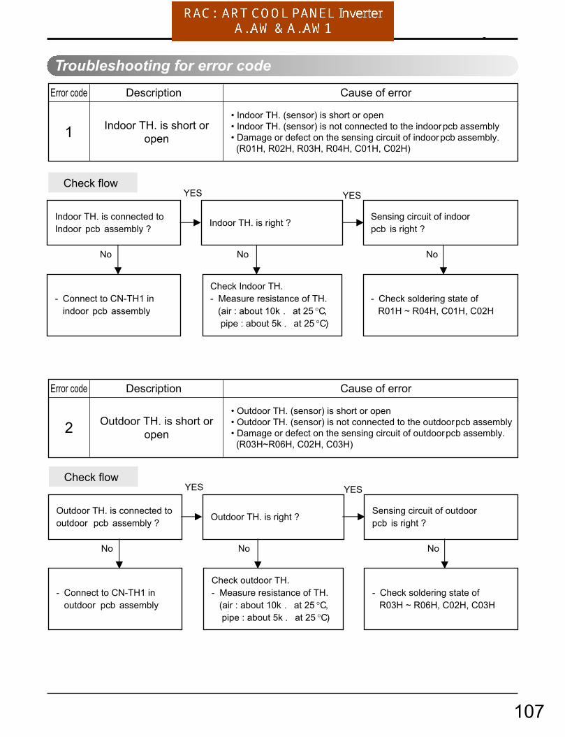
Troubleshooting Guide
Troubleshooting for error code
Description Cause of error
1• Indoor TH. (sensor) is short or open• Indoor TH. (sensor) is not connected to the indoor pcb assembly• Damage or defect on the sensing circuit of indoor pcb assembly. (R01H, R02H, R03H, R04H, C01H, C02H)
Indoor TH. is short oropen
Indoor TH. is connected to Indoor pcb assembly ? Indoor TH. is right ?
YES
No
- Connect to CN-TH1 in indoor pcb assembly
Sensing circuit of indoorpcb is right ?
No
Check Indoor TH.- Measure resistance of TH. (air : about 10k . at 25 °C, pipe : about 5k . at 25 °C)
YES
No
- Check soldering state of R01H ~ R04H, C01H, C02H
Check flow
2• Outdoor TH. (sensor) is short or open• Outdoor TH. (sensor) is not connected to the outdoor pcb assembly• Damage or defect on the sensing circuit of outdoor pcb assembly. (R03H~R06H, C02H, C03H)
Outdoor TH. is short oropen
DescriptionError code
Error code
Cause of error
Outdoor TH. is connected to outdoor pcb assembly ? Outdoor TH. is right ?
YES
No
- Connect to CN-TH1 in outdoor pcb assembly
Sensing circuit of outdoorpcb is right ?
No
Check outdoor TH.- Measure resistance of TH. (air : about 10k . at 25 °C, pipe : about 5k . at 25 °C)
YES
No
- Check soldering state of R03H ~ R06H, C02H, C03H
Check flow
107

Troubleshooting Guide
• 9K / 12K
4
• Heat-sink TH. is damaged(short or open).
• Heat-sink Temp. is over 95°C
• Damage or defect on the sensing circuit of outdoor pcb assembly. (R01H, R02H, C01H)
Heat-sink Temp. is over95°CHeat-sink TH.is open or short
Heat-sink TH. in INV-IC isRight ?
Sensing circuit of outdoorpcb is right ?
YES
No
Check heat-sink TH. - Measure resistance of TH. (about 10k . at 25 °C)
Heat-sink TH is connected to outdoor PCB assembly?
YES
No
- Connect to CN-TH2 in outdoor PCB assembly
No
- Check soldering state of R01H, R02H, C01H
Check flow
Description Cause of errorError code
108

Troubleshooting Guide
5
• Wrong or missing wiring between indoor and outdoor unit cable• Defect of communication components in indoor pcb assembly• Defect of communication components in outdoor pcb assembly• Defect of power supply components in outdoor pcb assembly• No ground connection in air conditioner unit (affected by noise in power source)
Communication Error
Wiring connectionIs right ?
Is the voltage of T/Block, in outdoor about
AC 220/240V ?
YES
No
Indoor Outdoor 1(BR) 1(BR) 2(BL) 2(BL)3(GN/YL) 3(GN/YL) 4(RD) 4(RD)
No
Check power connectorIs not connected to theT/Block in indoor unit.
Check flow
Is the voltage of GND & DC5V in Outdoor pcb about DC 5V ?
YES
No
Check FUSE, NF01/02J, PTC,Power Module, BD-01S in Outdoor pcb assembly
Communication circuit of indoor& outdoor pcb Is right ?
YES
No
Check IC01K, IC02K,D01K~D03K,ZD01K~ZD03K, R01K~R10K,C01K~C04K
Ground connection is installed ?(power outlet or outdoor chassis)
YES
No
Install ground connection from outdoorunit. (In case power outlet has no earthport)
Earth port
Description Cause of errorError code
109

Troubleshooting Guide
Cause of error
6
• Supplied power is not normal• Comp Connector (CN-U,V,W) is disconnected or inserted to wrong position• Compressor is damaged (coil short) replace compressor• Too much Refrigerant• Defect in outdoor pcb assembly replace pcb assembly
DC Peak Error
Supplied voltage toOutdoor pcb is aboutAC 220/240V ?
Is connector (CN-U,V,W)connected to compressor and inserted to pcb in right position ?
YES
No
Check power source
No
Check CN-U,V,W connector(U : RD, V : BL, W : YL)
Check flow
Refrigerant pressure is right ?
YES
No
Check refrigerant pressureand adjust.
Is the compressor right ?
YES
No
Check resistance Between U-V, V-W, U-W port.
→ Short / Open circuit (Comp.motor coil error) → normal : 1 ~2 .
Between U,V,W and Body °Ê normal : over10M .
Inverter components in outdoor pcb assembly areright ?
YES
No
* 9 K/12K ModelCheck
Short of SPM3 pins (GND - P, U, V, W pin) Direction of D01Z~D03Z, C08Z,10Z,12Z,16Z Assembling state of R01P ~ R21P & IC01P Assembling state of screw between INV-IC &
Heat-sink DC 15V output of Power module.
* 18 K ModelCheck
Short of SPM2 pins (GND – P, U, V, W pin) Direction of D01Z~D03Z, C08Z,10Z,12Z,16Z Assembling state of R01P ~ R21P & IC01P Assembling state of screw between INV-IC &
Heat-sink DC 15V output of Power module.
V
U
W
.
Description Cause of errorError code
110
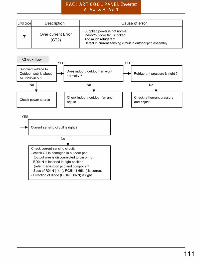
Troubleshooting Guide
7• Supplied power is not normal• Indoor/outdoor fan is locked• Too much refrigerant• Defect in current sensing circuit in outdoor pcb assembly
Over current Error(CT2)
Supplied voltage toOutdoor pcb is aboutAC 220/240V ?
Does indoor / outdoor fan worknormally ?
YES
No
Check power source
No
Check indoor / outdoor fan andadjust.
Check flow
Refrigerant pressure is right ?
YES
No
Check refrigerant pressureand adjust.
Current sensing circuit is right ?
YES
No
Check current sensing circuit.- check CT is damaged in outdoor pcb
(output wire is disconnected to pin or not)- BD01N is inserted in right position
(refer marking on pcb and component)- Spec of R01N (1k. ), R02N (1.65k. ) is correct- Direction of diode (D01N, D02N) is right
Description Cause of errorError code
111
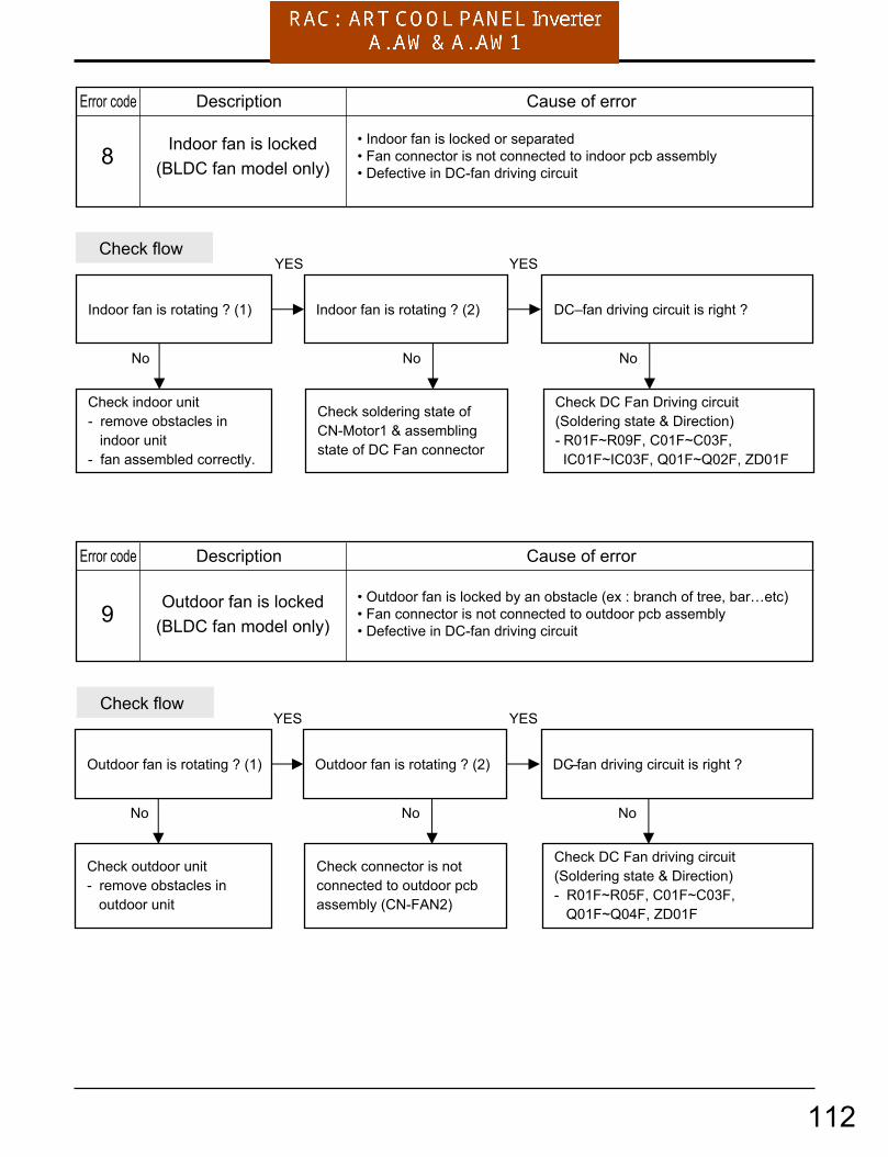
Troubleshooting Guide
8• Indoor fan is locked or separated• Fan connector is not connected to indoor pcb assembly• Defective in DC-fan driving circuit
Indoor fan is locked(BLDC fan model only)
Indoor fan is rotating ? (1) Indoor fan is rotating ? (2)
YES
No
Check indoor unit- remove obstacles in indoor unit- fan assembled correctly.
No
Check soldering state of CN-Motor1 & assemblingstate of DC Fan connector
Check flow
DC–fan driving circuit is right ?
YES
No
Check DC Fan Driving circuit(Soldering state & Direction)- R01F~R09F, C01F~C03F, IC01F~IC03F, Q01F~Q02F, ZD01F
9• Outdoor fan is locked by an obstacle (ex : branch of tree, bar…etc)• Fan connector is not connected to outdoor pcb assembly• Defective in DC-fan driving circuit
Outdoor fan is locked(BLDC fan model only)
Outdoor fan is rotating ? (1) Outdoor fan is rotating ? (2)
YES
No
Check outdoor unit- remove obstacles in outdoor unit
No
Check connector is not connected to outdoor pcbassembly (CN-FAN2)
Check flow
DC–fan driving circuit is right ?
YES
No
Check DC Fan driving circuit(Soldering state & Direction)- R01F~R05F, C01F~C03F, Q01F~Q04F, ZD01F
Description Cause of errorError code
Description Cause of errorError code
112

Troubleshooting Guide
10• D_pipe TH. is short or open • D_pipe TH. is not connected to the outdoor pcb assembly• Damage or defect on the sensing circuit of outdoor pcb assembly
D-Pipe TH. is short oropen
D_PIPE TH. is connected toOutdoor pcb assembly ? D_PIPE TH. is right ?
YES
No
Connect to CN-D_PIPE in outdoor pcb assembly
Sensing circuit of outdoorpcb is right ?
No
Check D_PIPE TH.- Measure resistance of TH. (about 200k. at 25°C.)
YES
No
- Check soldering state of R07H, R08H, C04H
Check flow
Description Cause of errorError code
113