lib, cap and sms - prime-kit.com€¦ · 2.2.2. sms 510 ... e51 209 reg. overflow e52 210...
TRANSCRIPT

LIB, CAP and SMSTools for Relays and Terminals
User�s Guide


Tools for Relays and TerminalsUser�s Guide
CAP, LIB andSMS
1MRS752008-MUM
Issued: 01.12.2001Version: P/07.02.2006
Contents1. About this manual ...................................................................13
1.1. Copyrights ...................................................................................131.2. Trademarks .................................................................................131.3. Guarantee ...................................................................................131.4. General .......................................................................................131.5. Use of symbols ............................................................................141.6. Abbreviations ..............................................................................141.7. Related documents .....................................................................151.8. Document revisions .....................................................................15
2. RED relay object types ...........................................................172.1. Description ..................................................................................17
2.1.1. Communication support ...................................................172.2. Installation and configuration ......................................................18
2.2.1. CAP 501/505 ....................................................................182.2.2. SMS 510 ..........................................................................182.2.3. LIB 510/MicroSCADA: installing and configuring REx
terminals ..........................................................................182.2.3.1. Installing terminal picture functions ..................182.2.3.2. Terminal picture function configuration ............192.2.3.3. Standard Configuration Tool functions .............202.2.3.4. Terminal parametrization .................................24
2.3. Object types general ...................................................................242.3.1. Projects ............................................................................242.3.2. Object types .....................................................................242.3.3. Object type groups ...........................................................242.3.4. Objects .............................................................................24
2.4. Supported object types ...............................................................252.4.1. REF 54x, REC 52x, REM 54x, RET 54x ..........................25
2.4.1.1. General ............................................................252.4.1.2. SW configuration ..............................................262.4.1.3. Apl configuration ..............................................292.4.1.4. Apl utilities ........................................................302.4.1.5. Correlation between SW configuration and
Apl configuration ..............................................342.4.1.6. Transducer settings ..........................................36
2.4.2. REX 52x ...........................................................................382.4.2.1. General ............................................................382.4.2.2. HW configuration ..............................................392.4.2.3. Standard configuration .....................................41
3

1MRS752008-MUM Tools for Relays and TerminalsUser�s Guide
CAP, LIB and SMS
2.4.2.4. Transducer settings ......................................... 432.4.3. REJ 5xx, REU 5xx ........................................................... 45
2.4.3.1. General ............................................................ 452.4.3.2. SW configuration .............................................. 462.4.3.3. Transducer settings ......................................... 47
2.4.4. REx 61x ........................................................................... 482.4.4.1. General ............................................................ 482.4.4.2. SW configuration .............................................. 492.4.4.3. Transducer settings ......................................... 51
2.5. Configuring communication settings ........................................... 532.5.1. General ............................................................................ 532.5.2. CAP 501/505, SMS 510 .................................................. 53
2.5.2.1. Communication support ................................... 542.5.3. LIB 500/510 in MicroSCADA ........................................... 55
2.5.3.1. Communication support ................................... 562.6. Application engineering information in LIB 500/510 ................... 56
2.6.1. General ............................................................................ 562.6.2. Process objects ............................................................... 572.6.3. Files ................................................................................. 57
2.6.3.1. REF 54x ........................................................... 582.6.3.2. REC 52x ........................................................... 602.6.3.3. REM 54x .......................................................... 612.6.3.4. RET 54x ........................................................... 632.6.3.5. REX 52x ........................................................... 652.6.3.6. REJ 5xx ............................................................ 672.6.3.7. REU 5xx ........................................................... 692.6.3.8. REx 61x ........................................................... 70
3. SPACOM relay object types .................................................. 733.1. Overview ..................................................................................... 73
3.1.1. Description ....................................................................... 733.1.2. Communication support ................................................... 73
3.2. Basic concepts/terminology ........................................................ 733.3. Installation and configuration ...................................................... 73
3.3.1. LIB 510/MicroSCADA: installing and configuring SPACOM relays picture functions ................................... 733.3.1.1. Installing relay picture functions ....................... 743.3.1.2. Relay picture function configuration ................. 753.3.1.3. Standard Configuration Tool functions ............. 753.3.1.4. Relay parametrization ...................................... 78
3.3.2. CAP 501/505 and SMS 510 ............................................ 783.3.3. Object Configuration Tool dialog ..................................... 78
4

1MRS752008-MUM CAP, LIB and SMS Tools for Relays and TerminalsUser�s Guide
3.3.3.1. Rack configuration page ..................................783.3.3.2. Transducers page ............................................80
3.3.4. Communication configuration ..........................................823.3.4.1. LIB 510 in MicroSCADA ...................................823.3.4.2. CAP 501/505 and SMS 510 .............................84
3.4. Application engineering information in LIB 510/MicroSCADA .....853.4.1. Process objects ................................................................853.4.2. Files .................................................................................85
3.4.2.1. Format pictures ................................................853.4.2.2. Texts ................................................................85
3.4.3. Process objects ................................................................853.4.3.1. Used abbreviations ..........................................863.4.3.2. SPAM050C, SPAM051C and SPAM052C .......873.4.3.3. SPCD3C21 .......................................................883.4.3.4. SPCD3C22 .......................................................883.4.3.5. SPCD3C23 .......................................................883.4.3.6. SPCJ1C20 .......................................................893.4.3.7. SPCJ1C7 .........................................................893.4.3.8. SPCJ1C8 .........................................................903.4.3.9. SPCJ2C30 .......................................................903.4.3.10. SPCJ3C3 .........................................................903.4.3.11. SPCJ3C48 .......................................................913.4.3.12. SPCJ3D35 .......................................................913.4.3.13. SPCJ4D24 .......................................................933.4.3.14. SPCJ4D29 .......................................................943.4.3.15. SPCJ4D34 .......................................................953.4.3.16. SPCJ4D36 .......................................................963.4.3.17. SPCJ4D40 .......................................................973.4.3.18. SPCJ4D44 .......................................................983.4.3.19. SACO16A3 .......................................................993.4.3.20. SACO16D2 ....................................................1063.4.3.21. SACO16D1B ..................................................1083.4.3.22. SACO16D2B ..................................................1113.4.3.23. SPCP3C2 .......................................................1133.4.3.24. SPCS2D37 .....................................................1133.4.3.25. SPCS3C4 .......................................................1143.4.3.26. SPCS4D11 .....................................................1153.4.3.27. SPCS4D12 .....................................................1163.4.3.28. SPCS4D13 .....................................................1173.4.3.29. SPCT2C17 .....................................................118
5
1MRS752008-MUM Tools for Relays and TerminalsUser�s Guide
CAP, LIB and SMS
3.4.3.30. SPCT2C5 ....................................................... 1183.4.3.31. SPCT2D38 ..................................................... 1193.4.3.32. SPCT2D46 ..................................................... 1203.4.3.33. SPCU1C1 ...................................................... 1213.4.3.34. SPCU1C6 ...................................................... 1213.4.3.35. SPCU1D39 .................................................... 1223.4.3.36. SPCU1D47 .................................................... 1223.4.3.37. SPCU3C14 .................................................... 1233.4.3.38. SPCU3C15 .................................................... 1243.4.3.39. SPCU3D45 .................................................... 1243.4.3.40. SPTO1C1 ....................................................... 1253.4.3.41. SPTO1C4 ....................................................... 1263.4.3.42. SPTO1D2 ....................................................... 1263.4.3.43. SPTO1D5 ....................................................... 1293.4.3.44. SPTO1D6 ....................................................... 1313.4.3.45. SPTO2C2 ....................................................... 1343.4.3.46. SPTO6D3 ....................................................... 1353.4.3.47. SPTO12D4 ..................................................... 1403.4.3.48. REC 501 ........................................................ 1423.4.3.49. SPCF 1D15 .................................................... 143
3.4.4. Format pictures and status texts .................................... 144
4. SPACOM Relay Setting Tool ............................................... 1454.1. Description ................................................................................ 145
4.1.1. Target systems .............................................................. 1454.1.2. Features/options ............................................................ 145
4.2. Tool environments .................................................................... 1454.2.1. Starting from LIB 510 in MicroSCADA ........................... 145
4.3. Relay Setting Tool .................................................................... 1474.3.1. Main view ....................................................................... 147
4.4. Using Relay Setting Tool .......................................................... 1494.4.1. File menu ....................................................................... 149
4.4.1.1. Importing ........................................................ 1494.4.1.2. Exporting ........................................................ 1504.4.1.3. Page Setup .................................................... 1514.4.1.4. Print Setup ..................................................... 1524.4.1.5. Printing ........................................................... 1524.4.1.6. Exit ................................................................. 154
4.4.2. View menu ..................................................................... 1544.4.2.1. Settings .......................................................... 1554.4.2.2. Registers ........................................................ 155
6

1MRS752008-MUM CAP, LIB and SMS Tools for Relays and TerminalsUser�s Guide
4.4.2.3. Setting Tool ....................................................1564.4.3. Transfers menu ..............................................................160
4.4.3.1. Upload parameters .........................................1614.4.3.2. Download parameters ....................................161
4.4.4. Tools menu ....................................................................1624.4.4.1. Compare ........................................................1624.4.4.2. Reset registers ...............................................1654.4.4.3. Change Active Setting Group .........................1654.4.4.4. View Transducers ..........................................1654.4.4.5. View Communication Settings .......................166
4.4.5. Help menu ......................................................................1664.4.5.1. About Setting Tool ..........................................166
5. RED Relay Setting Tool ........................................................1675.1. Description ................................................................................167
5.1.1. Features/Options ...........................................................1675.2. Tool Environments ....................................................................167
5.2.1. Starting from LIB 510 in MicroSCADA ...........................1675.2.2. Starting from CAP 501/505, SMS 510 ...........................170
5.3. Relay Setting Tool .....................................................................1705.3.1. General ..........................................................................1705.3.2. Start-up ..........................................................................170
5.3.2.1. Build Active Menu ..........................................1705.3.2.2. Import relay parameter settings from
external programs ..........................................1725.3.3. Main view .......................................................................173
5.4. Using Relay Setting Tool ...........................................................1745.4.1. File menu .......................................................................174
5.4.1.1. Importing ........................................................1755.4.1.2. Exporting ........................................................1755.4.1.3. Page Setup ....................................................1765.4.1.4. Print Setup .....................................................1775.4.1.5. Printing ...........................................................1785.4.1.6. Exit .................................................................180
5.4.2. View menu .....................................................................1815.4.3. Transfer menu ................................................................181
5.4.3.1. Upload ............................................................1825.4.3.2. Download .......................................................1825.4.3.3. Store ...............................................................1845.4.3.4. Reset (example) .............................................185
5.4.4. Tools menu ....................................................................1865.4.4.1. Compare ........................................................186
7

1MRS752008-MUM Tools for Relays and TerminalsUser�s Guide
CAP, LIB and SMS
5.4.4.2. Edit History ..................................................... 1885.4.4.3. View Transducers .......................................... 189
5.4.5. Options menu ................................................................ 1895.4.5.1. Resize Dialog ................................................. 1895.4.5.2. Rebuild Active Menu ...................................... 1905.4.5.3. Menu Configuration ........................................ 191
5.4.6. Help ............................................................................... 1965.4.6.1. About Relay Setting Tool ............................... 197
5.4.7. Monitoring and changing parameters ............................ 1975.4.7.1. RED menus .................................................... 1975.4.7.2. Tabbed pages ................................................ 1975.4.7.3. Parametrization .............................................. 198
6. Graphical I/O Setting Tool ................................................... 1996.1. General ..................................................................................... 1996.2. Start-up ..................................................................................... 199
6.2.1. Starting from CAP 501/505 or SMS 510 ....................... 1996.3. Main view .................................................................................. 2006.4. Using Graphical I/O Setting Tool .............................................. 201
6.4.1. Matrix pages .................................................................. 2016.4.1.1. Input Matrix .................................................... 2036.4.1.2. Output Matrix ................................................. 2046.4.1.3. Alarm LED Matrix ........................................... 206
6.4.2. File menu ....................................................................... 2086.4.2.1. Printing ........................................................... 209
6.4.3. Transfers Menu ............................................................. 2106.4.3.1. Upload ............................................................ 2106.4.3.2. Download ...................................................... 211
6.4.4. Help menu ..................................................................... 2126.4.4.1. Graphical I/O Setting Tool Help .................... 2126.4.4.2. Parameter Information ................................... 2136.4.4.3. About Setting Tool� ...................................... 213
7. DR-Collector Tool ................................................................. 2157.1. General ..................................................................................... 215
7.1.1. Communication support ................................................. 2157.1.2. Supported disturbance recorders .................................. 216
7.2. Using DR-Collector Tool ........................................................... 2167.2.1. General .......................................................................... 2167.2.2. Starting DR-Collector Tool ............................................. 216
7.2.2.1. Starting from LIB 510 in MicroSCADA ........... 2167.2.2.2. Starting from CAP 501/505 and SMS 510 ..... 217
8
1MRS752008-MUM CAP, LIB and SMS Tools for Relays and TerminalsUser�s Guide
7.2.3. DR-Collector Tool overview ...........................................2177.2.4. Menus ............................................................................219
7.2.4.1. File menu .......................................................2197.2.4.2. View menu .....................................................2227.2.4.3. Tools Menu ....................................................2237.2.4.4. Help menu ......................................................233
7.2.5. Toolbar buttons ..............................................................2337.3. Recorder Tool ...........................................................................234
7.3.1. General ..........................................................................2347.3.2. Functions .......................................................................2347.3.3. RE_54_ transient disturbance recorder (REF 54x,
REM 54x, REC 523, RET 54x) ......................................2367.3.4. Disturbance recorder REX 521 ......................................2367.3.5. Disturbance recorder SPCR 8C27 .................................2377.3.6. Internal disturbance recorders SPCD 2D55,
SPCD 3D53 ...................................................................2387.3.7. Internal disturbance recorders REU5xx, REJ 5xx,
REx 61x .........................................................................2397.3.8. Menus ............................................................................239
7.3.8.1. File menu .......................................................2397.3.8.2. View menu .....................................................2407.3.8.3. Transfers menu ..............................................2407.3.8.4. Reset menu ....................................................2447.3.8.5. Toolbar buttons ..............................................244
7.4. Using DR-Collector Tool over a remote connection ..................2457.5. Engineering information ............................................................246
7.5.1. LIB 500 menu configuration for DR-Collector Tool ........2467.5.2. Command procedures ...................................................2477.5.3. Configuring SRIO parameters when connected to
MicroSCADA ..................................................................2487.5.4. Other information ...........................................................248
8. SPA Terminal Emulator ........................................................2498.1. Description ................................................................................249
8.1.1. Communication support .................................................2498.1.2. Starting the program ......................................................2498.1.3. Exiting the program ........................................................2508.1.4. Communication setup ....................................................2508.1.5. Reading and sending of SPA messages .......................2508.1.6. SPA Terminal Emulator examples .................................251
9. Disturbance Draw Tool .........................................................2559.1. General .....................................................................................2559.2. Using Disturbance Draw Tool ...................................................255
9

1MRS752008-MUM Tools for Relays and TerminalsUser�s Guide
CAP, LIB and SMS
9.2.1. Starting .......................................................................... 2559.2.2. Opening COMTRADE File ............................................. 2559.2.3. Handling channels ......................................................... 256
9.2.3.1. Changing the scale of Y-axis ......................... 2569.2.3.2. Zooming in time axis ...................................... 2579.2.3.3. Moving in time axis ........................................ 2579.2.3.4. Selecting channels to be displayed ................ 2579.2.3.5. Goto trigger point ........................................... 2589.2.3.6. Goto marker ................................................... 2589.2.3.7. Title bars on channels .................................... 2589.2.3.8. Enable/Disable auto-scaling on all channels . 258
9.2.4. Using Markers ............................................................... 2589.2.4.1. Window menu ................................................ 2609.2.4.2. Help menu ...................................................... 262
9.2.5. Printing curves ............................................................... 2629.2.5.1. Print settings .................................................. 263
9.2.6. Displaying COMTRADE File Information ....................... 263
10.Power Quality Monitoring Tool .......................................... 26510.1.General .................................................................................... 26510.2.Start-up .................................................................................... 26510.3.Main view ................................................................................. 266
10.3.1.Menu bar ....................................................................... 26710.3.1.1. File menu ....................................................... 267
10.3.2.Toolbar .......................................................................... 27110.3.3.Tabbed page ................................................................. 27210.3.4.Visualization area .......................................................... 27310.3.5.Status bar ...................................................................... 275
10.4.Monitoring functionality ............................................................ 27610.4.1.On-line monitoring ......................................................... 27610.4.2.Monitoring of saved data ............................................... 277
11.Event Log Viewer ................................................................. 27911.1.General .................................................................................... 27911.2.Start-up .................................................................................... 27911.3.User interface ........................................................................... 280
11.3.1.Menu bar and toolbar commands .................................. 28111.3.2.Event view ..................................................................... 28211.3.3.Status bar ...................................................................... 282
11.4.Using the Event Log Viewer ..................................................... 28211.4.1.Uploading an event log .................................................. 282
11.4.1.1. Communication problems .............................. 28311.4.2.Saving an event log ....................................................... 284
10

1MRS752008-MUM CAP, LIB and SMS Tools for Relays and TerminalsUser�s Guide
11.4.3.Opening a saved event log ............................................28411.4.4.Exporting an event log into a text file .............................28511.4.5.Printing an event log ......................................................286
12.REx 61x DNP 3.0 point configuration .................................28712.1.General .....................................................................................28712.2.Start-up .....................................................................................28712.3.Using the DNP 3.0 point configuration dialog ...........................288
12.3.1.Entering the DNP point editing dialog ............................28812.3.2.Editing DNP points .........................................................288
12.3.2.1. Editing in general ...........................................28812.3.2.2. Class and UR flag ..........................................29112.3.2.3. Additional columns for analog points .............29212.3.2.4. Additional columns for counter points ............292
12.3.3.Export function ...............................................................29312.3.4.Exceptions .....................................................................29312.3.5.Exiting the dialog ............................................................293
13.Troubleshooting ...................................................................29513.1.Windows Installer appears when a program is started .............29513.2.Incorrect printouts .....................................................................296
14.Index ......................................................................................297
11

12

1MRS752008-MUM CAP, LIB and SMS Tools for Relays and TerminalsUser�s Guide
1. About this manual
1.1. CopyrightsThe information in this document is subject to change without notice and should not be construed as a commitment by ABB Oy. ABB Oy assumes no responsibility for any errors that may appear in this document.
In no event shall ABB Oy be liable for direct, indirect, special, incidental or consequential damages of any nature or kind arising from the use of this document, nor shall ABB Oy be liable for incidental or consequential damages arising from use of any software or hardware described in this document.
This document and parts thereof must not be reproduced or copied without written permission from ABB Oy, and the contents thereof must not be imparted to a third party nor used for any unauthorized purpose.
The software or hardware described in this document is furnished under a license and may be used, copied, or disclosed only in accordance with the terms of such license.
Copyright © 2006 ABB Oy All rights reserved.
1.2. TrademarksABB is a registered trademark of ABB Group. All other brand or product names mentioned in this document may be trademarks or registered trademarks of their respective holders.
1.3. GuaranteePlease inquire about the terms of guarantee from your nearest ABB representative.
1.4. GeneralThis manual provides thorough information on the relay object types and relay tools used in CAP 501, CAP 505, SMS 510 and LIB 510 applications.
Pictures shown are examples only, and they may represent older program versions.
Additional information such as the Release Note and README.TXT can be found on the program distribution media.
ABB Oy regularly provides standard training courses on its main products.The training program is available on the Internet at http://www.abb.com/substationautomation. Please contact your ABB representative for more information.
13

1MRS752008-MUM Tools for Relays and TerminalsUser�s Guide
CAP, LIB and SMS
1.5. Use of symbolsThis publication includes warning, caution, and information icons that point out safety related conditions or other important information. It also includes tip icons to point out useful information to the reader. The corresponding icons should be interpreted as follows:
Although warning hazards are related to personal injury, and caution hazards are associated with equipment or property damage, it should be understood that operation of damaged equipment could, under certain operational conditions, result in degraded process performance leading to personal injury or death. Therefore, comply fully with all warning and caution notices.
1.6. Abbreviations
The caution icon indicates important information or warning related to the concept discussed in the text. It might indicate the presence of a hazard which could result in corruption of software or damage to equipment or property.
The information icon alerts the reader to relevant facts and conditions.
The tip icon indicates advice on, for example, how to design your project or how to use a certain function.
IED Intelligent Electronic DeviceLAN Local Area NetworkLED Light-emitting diodeLON Local Operating Network,
communication protocol developed by EchelonPQ Power QualityPSN Project Structure NavigatorRAS Remote Access ServiceSPA Data communication protocol developed by ABBTCP/IP Transport Control Protocol/Internet Protocol; de facto
communication protocol standard for data transmission over networks
14

1MRS752008-MUM CAP, LIB and SMS Tools for Relays and TerminalsUser�s Guide
1.7. Related documents
1.8. Document revisions
Name of the manual Document IDLIB 500 4.0.4 Operation Manual 1MRS751885-MUMLIB 500 4.0.4 Configuration Manual 1MRS751880-MENLIB 510 4.0.4 Operation Manual 1MRS751888-MUMLIB 510 4.0.4 Configuration Manual 1MRS751886-MENLIB 500 *4.2 Operation Manual 1MRS755359LIB 500 *4.2 Configuration Manual 1MRS755360LIB 510 *4.2 Operation Manual 1MRS755361LIB 510 *4.2 Configuration Manual 1MRS755362SMS 510 User�s Guide 1MRS751267-MUMSYS 500 System Management,User�s Guide
1MRS751857-MEN
CD-ROM (Technical Descriptions of Functions)
1MRS750889-MCD
MEDREC16, Transient Disturbance Recorder manual
1MRS752341-MUM
Version SW revision number Date History
G n/a 31.03.2004 REF 54x 3.0H n/a 30.06.2004 REX 521 rev. E, Event Log Viewer,
IEC protocols in LIB 5x0K n/a 07.10.2004 REF 610 additions
New chapters: - 12. REx 61x DNP 3.0 point configuration- 13. Troubleshooting
L n/a 20.12.2004 RET 54x additionsM n/a 01.03.2005 Maintenance updatesN n/a 08.07.2005 Maintenance updatesP n/a 07.02.2006 SPA TCP/IP protocol added
Maintenance updates
15

16

1MRS752008-MUM CAP, LIB and SMS Tools for Relays and TerminalsUser�s Guide
2. RED relay object types
2.1. DescriptionAn object type is a package that contains relay configuration descriptions, profile files, standard function pictures and data files, format pictures and texts.
RED relay object types package is used in the CAP 501 Relay Setting Tools, CAP 505 Relay Product Engineering Tools, SMS 510 Substation Monitoring System and MicroSCADA application libraries LIB 500/510.
Object types are named according to the relay type. For example, all configuration descriptions of the relays REF 541, REF 543 and REF 545 will be stored under the object type REF 54x.
The purpose of this manual is to describe the usage of relay and terminal tools which are under the LIB, CAP and SMS products.
2.1.1. Communication supportWhen the following protocols are used, the supplied relay tools provide the most comprehensive support for the RED relay objects.
Table 2.1.1-1 Supported communication protocols
In addition to the protocols above, in LIB 500/510 the following protocols are partly supported for certain relay types with certain restrictions. When using the protocols below, only parametrization with the RED Relay Setting Tool and disturbance recording uploading with the DR-Collector Tool (but not automated upload) is supported. This means that for example the Event Editor or the PQ-Monitoring Tool cannot be used with these protocols.
CAP 501 SPA, SPA TCP/IP
CAP 505 LON, SPA, SPA TCP/IP
SMS 510 LON, SPA
LIB 500/510 LON, SPA
Table 2.1.1-2 Partly supported communication protocols in LIB 500/510
Protocol Relay types Condition RemarksIEC 60870-5-101 REF 54x, REM 54x, REC 52x,
REX 52x, RET 54x- All but REC 52x require either a
COM 6xx or KU-2000 gatewayIEC 61850-8 All other RED object types but
REC 52xOnly with SYS 600
Requires a SPA-ZC 40x communication gateway
17

1MRS752008-MUM Tools for Relays and TerminalsUser�s Guide
CAP, LIB and SMS
2.2. Installation and configuration
2.2.1. CAP 501/505After a RED relay has been inserted (use the Add function) to the project tree, it has to be configured with the Properties/Attributes function, see �General Object Attributes/Communication page� on page 54. This is described in Section 2.4. on page 25 (Supported object types). Communication settings are described in Section 2.5. on page 53 (Configuring communication settings).
SMS 510Please see the SMS 510 User�s Guide.
2.2.2. LIB 510/MicroSCADA: installing and configuring REx terminalsThe following steps and tools are required for a REx terminal picture function in MicroSCADA:
1. Installation of the terminal picture function (Installation Tool)2. Configuration of the terminal picture function (Standard Configuration Tool)
� Attributes � REx Configuration (Object Configuration Tool)� Communication settings (CConfig Tool)� Event handling (Event Editor)� Configuring representations (Representation Tool)
3. Terminal parametrization (RED Relay Setting Tool)
Steps one and two are shortly described in the following sections, but relay parametrization is beyond the scope of this manual, please see the LIB 510 Operation Manual, RED Relay Setting Tool.
Steps 1 and 2 above are accessed from the Tool Manager/Picture Editor. LIB 500 Configuration Manual (Introduction) gives a general description of the principles for installing and configuring picture functions. For every terminal a separate picture function is added to the process picture. Please see the Operator�s Manual and the Technical Reference Manual of the relevant terminal for further information.
2.2.2.1. Installing terminal picture functionsIn the installation tool, choose LIB4/LIB 510/PROTECTION & CONTROL. Select an appropriate object type, for example REF 54x and click once by mouse. After the RED standard function has been highlighted, enter a Picture Function Name for the function and click the Install button. Place the function anywhere in the base picture.
18

1MRS752008-MUM CAP, LIB and SMS Tools for Relays and TerminalsUser�s Guide
Install_REx
Fig. 2.2.2.1.-1 The procedure for installing a terminal picture function. Terminal picture function REF1 was successfully installed; the icon is visible in the upper left corner.
2.2.2.2. Terminal picture function configurationThe following flowchart shows the procedure of adding and preparing relay terminals for the process picture. This example applies to REF 54x.
19

1MRS752008-MUM Tools for Relays and TerminalsUser�s Guide
CAP, LIB and SMS
Fig. 2.2.2.2.-1 The procedure of the terminal configuration
The Object Configuration Tool is opened from the Tools menu of the Standard Configuration Tool. The configuration of the relay can be divided into four phases.
1. Relay terminal object type selection and configuration, SW library and APL library (Object Configuration Tool). (Function is described in Section 2.4. on page 25).
2. Storing terminal specific data (for example communication type in CConfig tool). (Function is described in Section 2.5. on page 53).
3. Event configuration (Event Editor). (Function is described in the LIB 510 Configuration Manual).
4. Storing terminal picture function data is done by the Standard Configuration Tool by selecting Apply or OK.
2.2.2.3. Standard Configuration Tool functionsSelect the terminal picture function. Start the Standard Configuration Tool to modify the configurable attributes and to start the REx Configuration Tool. The pages Attributes and Tools are described in this section. The Representation Tool in the Tools menu is not described.
Before starting the configuration, please ensure that the base system objects concerning the stations and nodes are correctly configured.
20
1MRS752008-MUM CAP, LIB and SMS Tools for Relays and TerminalsUser�s Guide
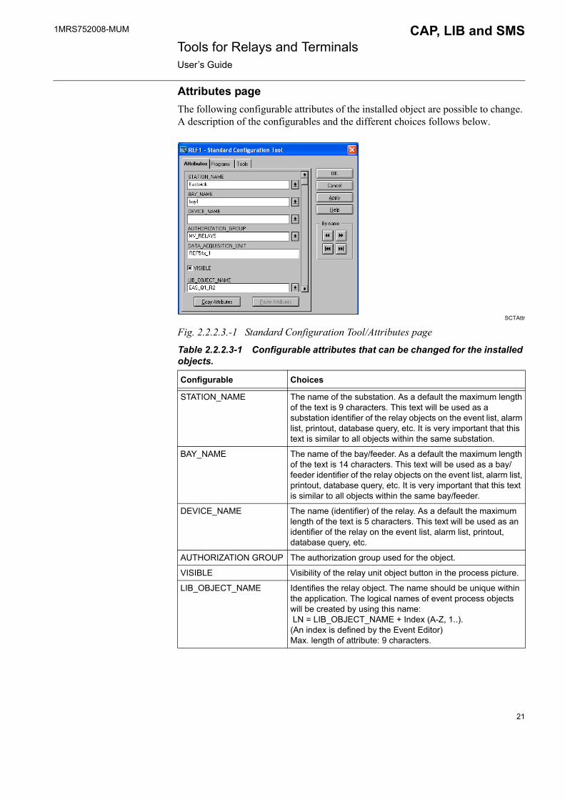
Attributes pageThe following configurable attributes of the installed object are possible to change. A description of the configurables and the different choices follows below.
SCTAttr
Fig. 2.2.2.3.-1 Standard Configuration Tool/Attributes page
Table 2.2.2.3-1 Configurable attributes that can be changed for the installed objects.
Configurable Choices
STATION_NAME The name of the substation. As a default the maximum length of the text is 9 characters. This text will be used as a substation identifier of the relay objects on the event list, alarm list, printout, database query, etc. It is very important that this text is similar to all objects within the same substation.
BAY_NAME The name of the bay/feeder. As a default the maximum length of the text is 14 characters. This text will be used as a bay/feeder identifier of the relay objects on the event list, alarm list, printout, database query, etc. It is very important that this text is similar to all objects within the same bay/feeder.
DEVICE_NAME The name (identifier) of the relay. As a default the maximum length of the text is 5 characters. This text will be used as an identifier of the relay on the event list, alarm list, printout, database query, etc.
AUTHORIZATION GROUP The authorization group used for the object.
VISIBLE Visibility of the relay unit object button in the process picture.
LIB_OBJECT_NAME Identifies the relay object. The name should be unique within the application. The logical names of event process objects will be created by using this name: LN = LIB_OBJECT_NAME + Index (A-Z, 1..).(An index is defined by the Event Editor) Max. length of attribute: 9 characters.
21

1MRS752008-MUM Tools for Relays and TerminalsUser�s Guide
CAP, LIB and SMS
Saving relay data to the picture functionAfter you have configured the relay terminal using the configuration tools, the data has to be saved to the picture function. This is done by using the Standard Configuration Tool commands by selecting OK or Apply.
Copying picture function dataTo copy picture function data and to paste it into another picture function, use the commands Copy attributes and Paste attributes in the Standard Configuration Tool. After you have copied the picture function data, open the Object Configuration Tool and make the necessary definitions (addresses etc.).
Deleting picture functionsPicture functions that have no connections to databases can be deleted directly in the Picture Editor. To delete a picture function element:
� Select the element with the selector
� Then click at the border of the element.� Choose Delete in the Edit menu and the element disappears. This can also be
done by pressing Delete on the keyboard.
Tools page
SCTTools
Fig. 2.2.2.3.-2 The Standard Configuration Tool dialog
The following tools can be started from the Tools page in the Standard Configuration Tool:
� Object Configuration Tool for selection of terminal type and application library (Function is described in Section 2.4. on page 25).
� CConfig Tool for communication settings (Function is described in Section 2.5. on page 53).
22

1MRS752008-MUM CAP, LIB and SMS Tools for Relays and TerminalsUser�s Guide
� Event Editor for event handling (Function is described in the LIB 510 Configuration Manual).
� Representation Tool for picture function symbol used for the terminal object.
Object Configuration Tool� The standard function parameters for the relay unit are configured via the Object
Configuration Tool.
The Object Configuration Tool is started from the Standard Configuration Tool by selecting Tools/Object Configuration Tool.
The data for the units is read from the REF 54x object type library. These descriptions are stored in the directory lib4/fmod/sm_red.
The following example concerns the REF 54x relay.
Fig. 2.2.2.3.-3 The dialog appearing when REF 54x Configuration is selected
23

1MRS752008-MUM Tools for Relays and TerminalsUser�s Guide
CAP, LIB and SMS
2.2.2.4. Terminal parametrizationAfter the terminal picture function configuration, the terminals are parametrized by the RED Relay Setting Tool.
2.3. Object types general
2.3.1. ProjectsA project is a collection of object instances arranged in a hierarchical order. Object hierarchy is achieved by the use of nodes. Each node behaves like a directory in a file system where each directory may contain files (in this case object instances). A project always has a root node (resembling the root directory in a file system) and it is also possible that this is the only node in the whole project. In CAP 5xx the default project is named SOST for Simple Object Selection Tool. In MicroSCADA both the project and directory name is PRJ in the PROTECTION directory under application.
In technical terms, a project is stored on disk in directories. Each project has its home root directory, for example SOST. The next directory level has OBJ#### directories where #### stands for a sequence number. Each object has a home directory of its own in the directory structure, for example SOST\OBJ0001.
2.3.2. Object typesObject types determine the information structure and functionality of an object instance.
All dialogs and program codes that control the behaviour and structural design of the object instance are stored in the object type resource files. This relationship between object types and object instances resembles drivers in an operating system, where some drivers control physical devices and some control the behaviour of the operating environment itself.
2.3.3. Object type groupsObject type group can be considered as a collection of object types that serve the same purpose. For example, among a number of other types, the SPACOM andREF 54x object types belong to the object type group Protection & Control.
2.3.4. ObjectsEach object in a project is an instance of an object type. Generally applicable information is taken from the object type, while the instance stores settings, e.g. parameter values. These values are later used by the object type or by a tool that is adapted to use the information structure of the object.
The object type determines the file structure for the object instance. Some object types prefer to save all object specific parameters in a single file in the object directory. Other object types use subdirectories with a various number of files. Tools that have been adapted for use with the object type information structure then use object information stored in these parameter files when the object instance is selected for a tool.
24

1MRS752008-MUM CAP, LIB and SMS Tools for Relays and TerminalsUser�s Guide
2.4. Supported object types
2.4.1. REF 54x, REC 52x, REM 54x, RET 54xThis paragraph describes the operation and properties of the object types REF 54x, REC 52x, REM 54x and RET 54x. However, as these object types share the same operating principle, this paragraph refers to the REF 54x object type only.
2.4.1.1. GeneralThe REF 54x object type configures object instances for REF 541, REF 543 and REF 545 terminals. The software configuration determines which REF terminal is being configured. Used function blocks determine the relay functionality. This information is stored in the application configuration. The REF 54x object type only configures the object instance, no communication takes place against the actual relay. When an object instance is configured, it is possible to apply its configuration in an appropriate tool. For instance, Relay Setting Tool, Relay Configuration Tool and the Relay Mimic Editor apply to object instances that belong to the REF 54x object type.
In the REF 54x configuration dialog you can choose the following functions:
� Select relay unit software and application configurations� Save an application configuration to the application library� Delete an application from the application library� Export from the application library � Import to the application library� Receive an application from the relay to the user application library
The page REF 54x Config is divided into two sections: SW configuration and Apl configuration.
25

1MRS752008-MUM Tools for Relays and TerminalsUser�s Guide
CAP, LIB and SMS
Fig. 2.4.1.1.-1 The REF 54x object type dialog
2.4.1.2. SW configuration
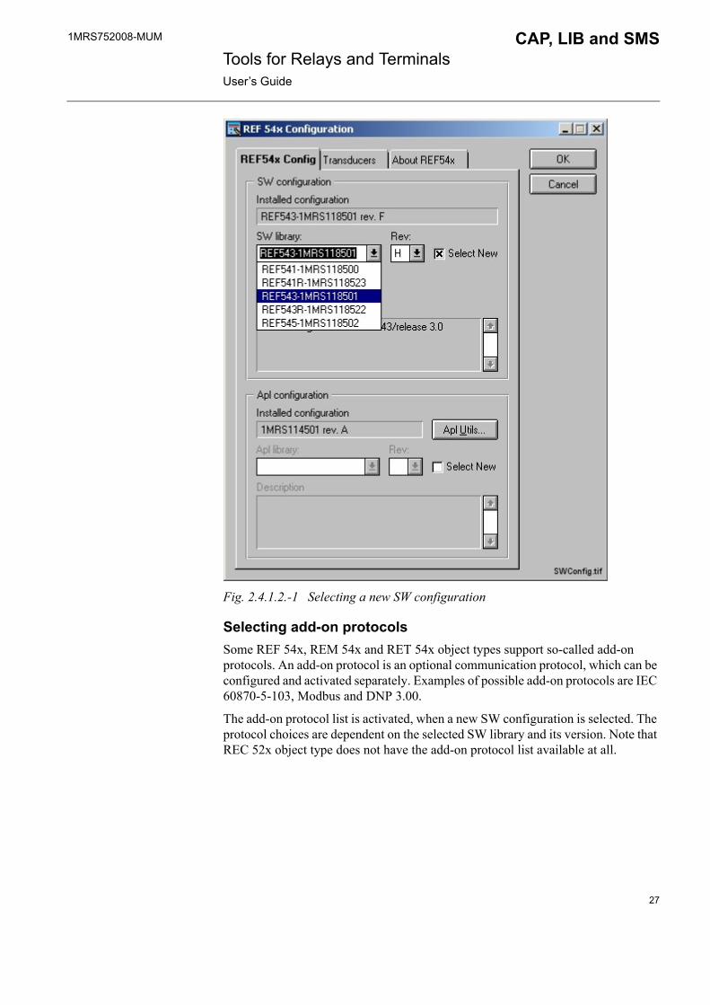
Selecting SW configurationA new SW configuration can be selected from the SW library list. Before selecting a new SW configuration, the SW library list must be activated by checking the Select New check box. You can select a specific SW library version from the Rev list.
The Installed configuration field displays the most recently installed SW configuration.
26
1MRS752008-MUM CAP, LIB and SMS Tools for Relays and TerminalsUser�s Guide
Fig. 2.4.1.2.-1 Selecting a new SW configuration
Selecting add-on protocolsSome REF 54x, REM 54x and RET 54x object types support so-called add-on protocols. An add-on protocol is an optional communication protocol, which can be configured and activated separately. Examples of possible add-on protocols are IEC 60870-5-103, Modbus and DNP 3.00.
The add-on protocol list is activated, when a new SW configuration is selected. The protocol choices are dependent on the selected SW library and its version. Note that REC 52x object type does not have the add-on protocol list available at all.
27

1MRS752008-MUM Tools for Relays and TerminalsUser�s Guide
CAP, LIB and SMS
Fig. 2.4.1.2.-2 Selecting a new add-on protocol
It must be noticed that the add-on protocol selection made on this dialog does not activate the protocol in the relay: the selection is only informative by giving an input to other tools. For example, the protocol mapping for Modbus and DNP 3.00 protocols is made separately by the Protocol Mapping Tool, and the selected protocol is activated by the Relay Download Tool. The visibility of the correct add-on protocol specific parameters in the Relay Setting Tool is determined by this setting as well. The parameter visiblity requires also that the relay application has been compiled by the Relay Configuration Tool using the correct SW/Apl configuration selections.
28

1MRS752008-MUM CAP, LIB and SMS Tools for Relays and TerminalsUser�s Guide
2.4.1.3. Apl configuration
Selecting Apl configurationA new Apl configuration can be selected from the Apl library list. Before selecting a new Apl configuration, the Apl library list must be activated by checking the Select New check box. You can select a specific application configuration version from the Rev list. If the Apl configuration is a �user-made� application (see Fig. 2.4.1.4.-2), it has no version number.
The Installed configuration field shows the most recently installed Apl configuration.
The Description field shows the application description.
AlpConf
Fig. 2.4.1.3.-1 Selecting a new Apl configuration. The Apl library list also contains applications made by the user.
29
1MRS752008-MUM Tools for Relays and TerminalsUser�s Guide
CAP, LIB and SMS
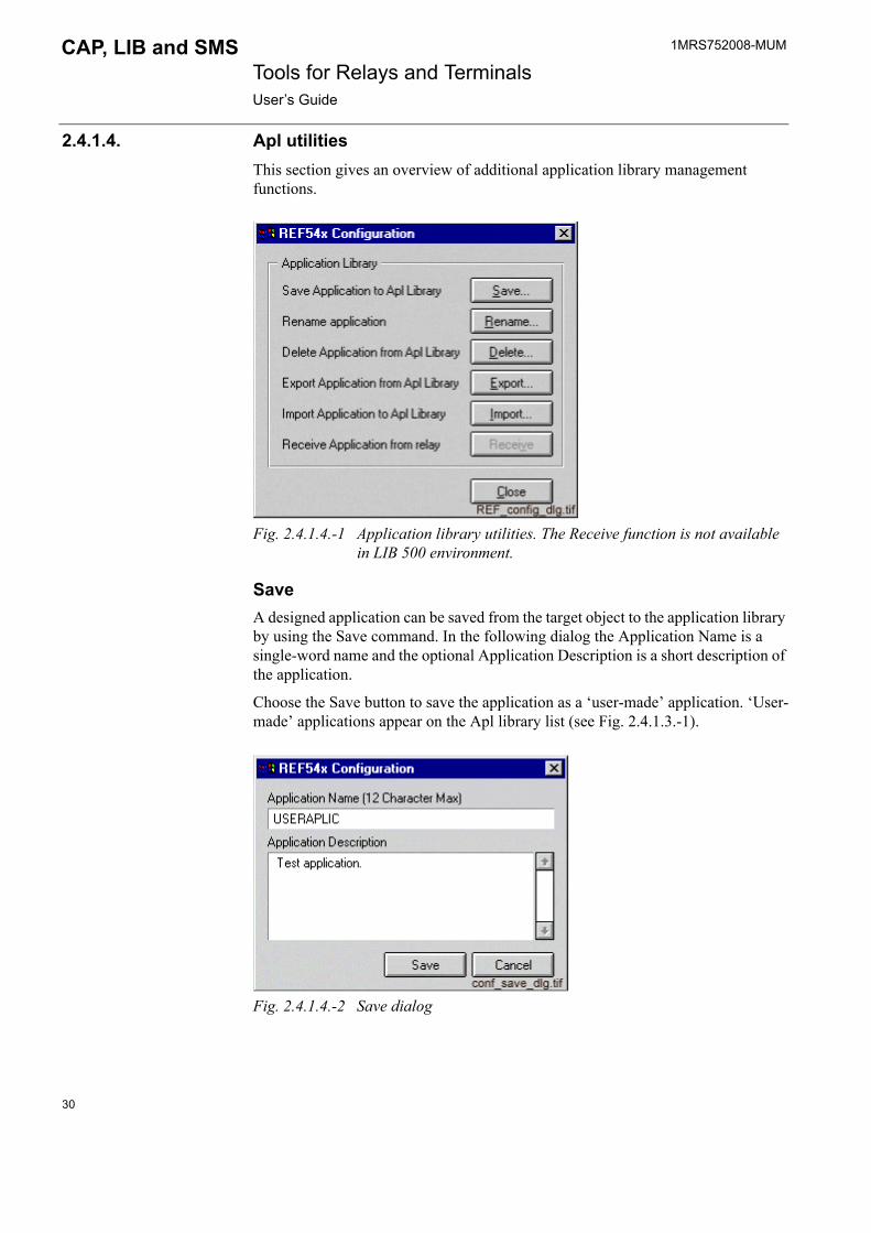
2.4.1.4. Apl utilitiesThis section gives an overview of additional application library management functions.
Fig. 2.4.1.4.-1 Application library utilities. The Receive function is not available in LIB 500 environment.
SaveA designed application can be saved from the target object to the application library by using the Save command. In the following dialog the Application Name is a single-word name and the optional Application Description is a short description of the application.
Choose the Save button to save the application as a �user-made� application. �User-made� applications appear on the Apl library list (see Fig. 2.4.1.3.-1).
Fig. 2.4.1.4.-2 Save dialog
30
1MRS752008-MUM CAP, LIB and SMS Tools for Relays and TerminalsUser�s Guide
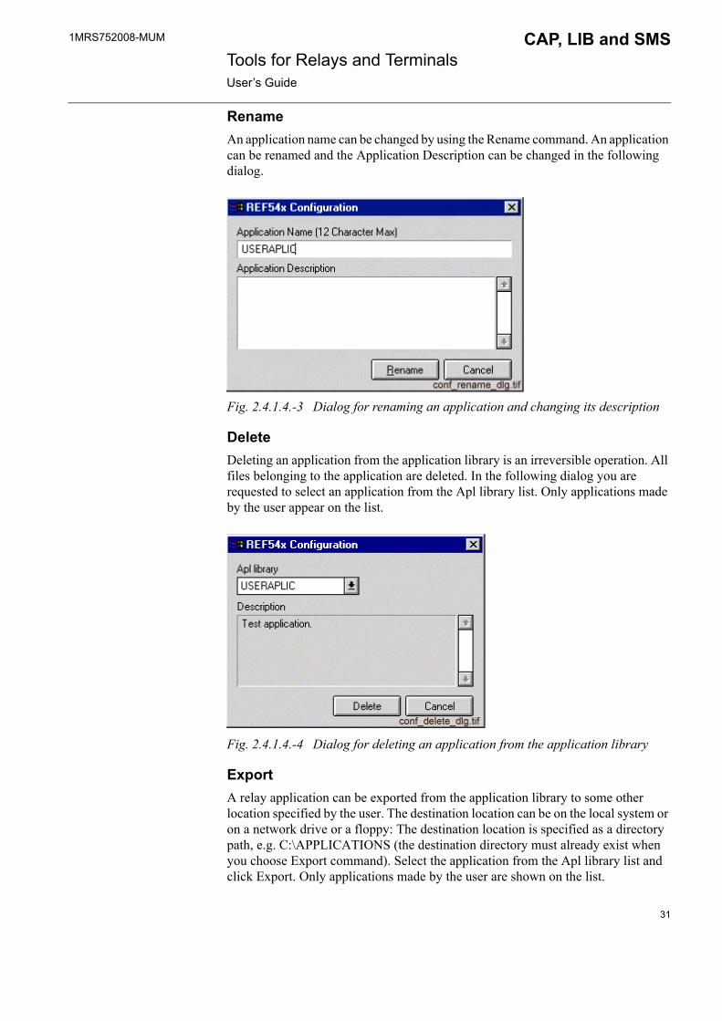
RenameAn application name can be changed by using the Rename command. An application can be renamed and the Application Description can be changed in the following dialog.
Fig. 2.4.1.4.-3 Dialog for renaming an application and changing its description
DeleteDeleting an application from the application library is an irreversible operation. All files belonging to the application are deleted. In the following dialog you are requested to select an application from the Apl library list. Only applications made by the user appear on the list.
Fig. 2.4.1.4.-4 Dialog for deleting an application from the application library
ExportA relay application can be exported from the application library to some other location specified by the user. The destination location can be on the local system or on a network drive or a floppy: The destination location is specified as a directory path, e.g. C:\APPLICATIONS (the destination directory must already exist when you choose Export command). Select the application from the Apl library list and click Export. Only applications made by the user are shown on the list.
31

1MRS752008-MUM Tools for Relays and TerminalsUser�s Guide
CAP, LIB and SMS
An example of the usage of this export function is e.g. when the relay application is made by CAP tools and should be transferred to LIB 500/510. Before it can be taken into use, it should also be imported by the Import function. More information is provided in the section dealing with importing.
Fig. 2.4.1.4.-5 Dialog for exporting an application
ImportThe import function adds applications to the Apl library. After you have exported the application, you should import it to the target system in order to add the application to the Apl list. Please ensure that the REF 54x version, which is imported, is the same version or is compatible with the REF 54x version to which it is imported.
If the applications are exported by using the REF 54x object type version 1.2.4 or later, select the option Compressed application file. Give a full path of the file. In this case the application subject to import is always in a compressed format.
If the application is exported by using an earlier version than the REF 54x object type version 1.2.4, select the option Uncompressed application folder. Give a path of the folder containing the application.
Click the Import button in order to import the an application to the Apl library.
32

1MRS752008-MUM CAP, LIB and SMS Tools for Relays and TerminalsUser�s Guide
Fig. 2.4.1.4.-6 Import dialog
ReceiveA Relay application can be received from the relay to the user application library by using the Receive command. After clicking the Receive button, the following dialog requesting a confirmation appears on the screen.
Fig. 2.4.1.4.-7 Dialog for confirming selection
If the Receiving process was completed successfully, the following dialog appears for the naming of the application.
At this moment, it is only possible to receive Relay Setting Tool configuration from the relay. This means that the received application contains data only for the Relay Setting Tool and data e.g. for the Event Editor cannot be received from the relay.
33

1MRS752008-MUM Tools for Relays and TerminalsUser�s Guide
CAP, LIB and SMS
Fig. 2.4.1.4.-8 Dialog for naming application
2.4.1.5. Correlation between SW configuration and Apl configurationBoth the SW configuration and the Apl configuration contain references for the separate function blocks included in the relay application. The SW configuration defines all the possible function blocks and their revisions, which can be used. The Apl configuration includes only the function blocks currently in use. It is extremely important that the selected Apl configuration has been compiled for the correct SW configuration (compilation is made by the Relay Configuration Tool in CAP 505).
If the function block revisions of the selected Apl configuration do not match with the selected SW configuration, the relay tools may get wrong information about the relay. It should be noticed that the relay works correctly regardless of this possible mismatch; it is only the image of the relay application, whose some details may cause relay tools to behave incorrectly.
The function block revisions are checked when trying to save the selections. Since there are two different cases tied to their severity, there are also two possible warning messages. A less critical case is when the function block revisions of the Apl configuration are older compared to the selected SW configuration. This is quite normal, when you upgrade the connected relay, but still have the old Apl configuration selected. In this case, a warning message will be shown (see Fig. 2.4.1.5.-1):
34

1MRS752008-MUM CAP, LIB and SMS Tools for Relays and TerminalsUser�s Guide
Config_mismatch_old_appl.
Fig. 2.4.1.5.-1 Warning about a configuration mismatch (older application)
A more serious case is when you try to select an Apl configuration intended for a newer SW configuration. Since this kind of an application may contain features not supported by the older relay revision, selecting this combination is never recommended. In this case, a warning message will be shown (see Fig. 2.4.1.5.-2):
Config_mismatch_new_appl.
Fig. 2.4.1.5.-2 Warning about a configuration mismatch (newer application)
Both these situations can be corrected by recompiling the relay application or by making another selection. However, since the mismatch message is only informative, the mismatching configuration selections can also be accepted and saved.
35
1MRS752008-MUM Tools for Relays and TerminalsUser�s Guide
CAP, LIB and SMS
2.4.1.6. Transducer settings
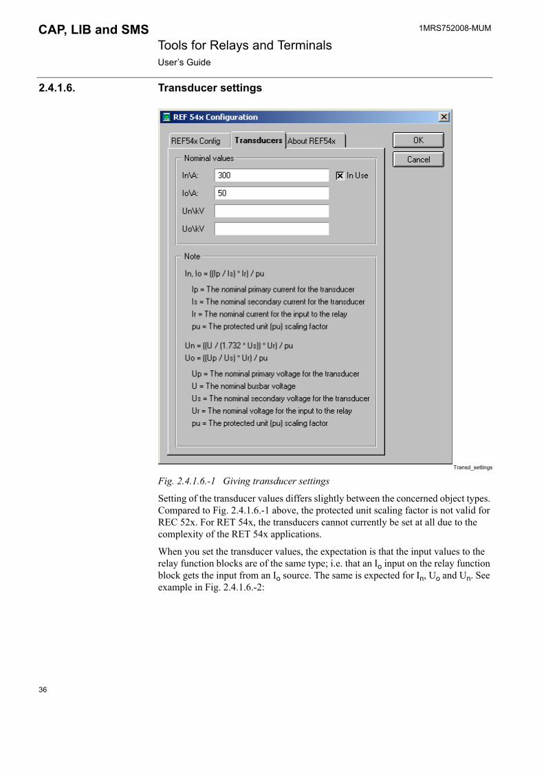
Transd_settings
Fig. 2.4.1.6.-1 Giving transducer settings
Setting of the transducer values differs slightly between the concerned object types. Compared to Fig. 2.4.1.6.-1 above, the protected unit scaling factor is not valid for REC 52x. For RET 54x, the transducers cannot currently be set at all due to the complexity of the RET 54x applications.
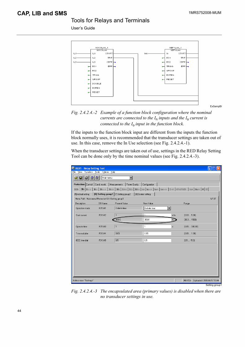
When you set the transducer values, the expectation is that the input values to the relay function blocks are of the same type; i.e. that an Io input on the relay function block gets the input from an Io source. The same is expected for In, Uo and Un. See example in Fig. 2.4.1.6.-2:
36

1MRS752008-MUM CAP, LIB and SMS Tools for Relays and TerminalsUser�s Guide
ExSampBI
Fig. 2.4.1.6.-2 Example of function block configuration where the In inputs are connected to In inputs on the function block and the Io inputs are connected to Io function block inputs.
If the inputs to the function block input are different from the inputs the function block normally uses, it is recommended that the transducer settings are taken out of use. Remove the In Use selection (see Fig. 2.4.1.6.-1).
When the transducer settings are taken out of use, settings in the RED Relay Setting Tool can be done only by the time nominal values (see Fig. 2.4.1.6.-3).
relay_setting_tool
Fig. 2.4.1.6.-3 The encapsulated area (primary values) is disabled when there are no transducer settings in use.
37
1MRS752008-MUM Tools for Relays and TerminalsUser�s Guide
CAP, LIB and SMS
2.4.2. REX 52xThis section describes the REX 52x object type and its properties.
2.4.2.1. GeneralThe REX 52x object type configures object instances for REX 521 terminal. The Hardware (HW) configuration determines, which REX terminal is being configured. Used function blocks determine the relay functionality. This information is stored in the Standard Configuration Tool. The REX 52x object type only configures the object instance, no communication takes place against the actual relay. When an object instance is configured, you can apply its configuration in an appropriate tool. For instance, Relay Setting Tool applies to object instances that belong to the REX 52x object type.
Use the REX 52x configuration dialog to select the relay unit HW and Standard Configurations. The REX 52x Config page (see Fig. 2.4.2.1.-1) is divided into two sections: HW configuration (described in Section 2.4.2.2. on page 39) and Standard configuration (described in Section 2.4.2.3. on page 41).
38

1MRS752008-MUM CAP, LIB and SMS Tools for Relays and TerminalsUser�s Guide
Fig. 2.4.2.1.-1 REX 52x Config page is divided into two sections: Hardware configuration and Standard configuration.
2.4.2.2. HW configuration
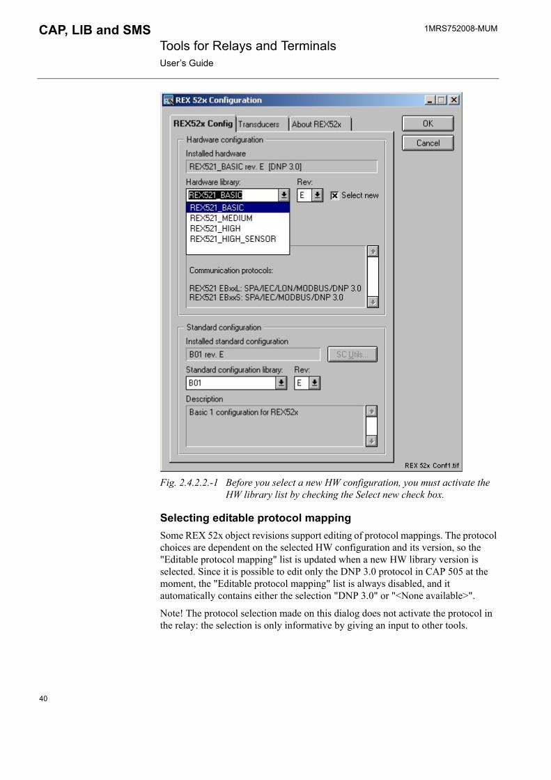
Selecting HW configurationThe HW configuration can be selected from a list where all supported HW configurations for the specific relay type are listed. Before you select a new HW configuration, you must activate the HW library list by checking the Select New check box (see Fig. 2.4.2.2.-1). From the Rev list you can select a specific HW library version. The Installed hardware field displays the most recently installed HW configuration.
39
1MRS752008-MUM Tools for Relays and TerminalsUser�s Guide
CAP, LIB and SMS
Fig. 2.4.2.2.-1 Before you select a new HW configuration, you must activate the HW library list by checking the Select new check box.
Selecting editable protocol mappingSome REX 52x object revisions support editing of protocol mappings. The protocol choices are dependent on the selected HW configuration and its version, so the "Editable protocol mapping" list is updated when a new HW library version is selected. Since it is possible to edit only the DNP 3.0 protocol in CAP 505 at the moment, the "Editable protocol mapping" list is always disabled, and it automatically contains either the selection "DNP 3.0" or "<None available>".
Note! The protocol selection made on this dialog does not activate the protocol in the relay: the selection is only informative by giving an input to other tools.
40

1MRS752008-MUM CAP, LIB and SMS Tools for Relays and TerminalsUser�s Guide
Fig. 2.4.2.2.-2 Selecting editable protocol
2.4.2.3. Standard configuration
Selecting standard configurationThe standard configuration can be selected from a list where all available standard configurations for the specific HW configuration are listed. A specific Standard configuration version can be selected from the Rev list (see Fig. 2.4.2.3.-1). The Installed standard configuration field shows the most recently installed standard configuration. The Description field shows the Standard configuration description.
41

1MRS752008-MUM Tools for Relays and TerminalsUser�s Guide
CAP, LIB and SMS
Fig. 2.4.2.3.-1 A specific standard configuration can be selected from the Standard configuration library. The Installed standard configuration field shows the most recently installed standard configuration.
42

1MRS752008-MUM CAP, LIB and SMS Tools for Relays and TerminalsUser�s Guide
2.4.2.4. Transducer settings
Transducers
Fig. 2.4.2.4.-1 Giving transducer setting
When you set the transducer values, the expectation is that the input values of the relay function blocks are of the same type; i.e. that an Io input on the relay function block gets the input from an Io source. The same is expected for In, Uo and Un. See example in Fig. 2.4.2.4.-2:
43
1MRS752008-MUM Tools for Relays and TerminalsUser�s Guide
CAP, LIB and SMS
ExSampBI
Fig. 2.4.2.4.-2 Example of a function block configuration where the nominal currents are connected to the In inputs and the Io current is connected to the Io input in the function block.
If the inputs to the function block input are different from the inputs the function block normally uses, it is recommended that the transducer settings are taken out of use. In this case, remove the In Use selection (see Fig. 2.4.2.4.-1).
When the transducer settings are taken out of use, settings in the RED Relay Setting Tool can be done only by the time nominal values (see Fig. 2.4.2.4.-3).
Setting group1
Fig. 2.4.2.4.-3 The encapsulated area (primary values) is disabled when there are no transducer settings in use.
44

1MRS752008-MUM CAP, LIB and SMS Tools for Relays and TerminalsUser�s Guide
2.4.3. REJ 5xx, REU 5xxThis section describes the operation and properties of the object types REJ 5xx and REU 5xx. However, as these object types share the same operating principle, only REJ5xx object type is mentioned in this section.
2.4.3.1. GeneralThe REJ 5xx object type configures object instances for REJ 511, REJ 521, REJ 513, REJ 523, REJ 515, REJ 525, REJ 517 and REJ 527 terminals. The software configuration determines which REJ terminal is being configured. Used function blocks determine the relay functionality. This information is stored in the application configuration.
You can use the REJ 5xx configuration dialog to select a relay unit software and to save transducer settings.
Fig. 2.4.3.1.-1 The REJ5xx Object type dialog
45
1MRS752008-MUM Tools for Relays and TerminalsUser�s Guide
CAP, LIB and SMS
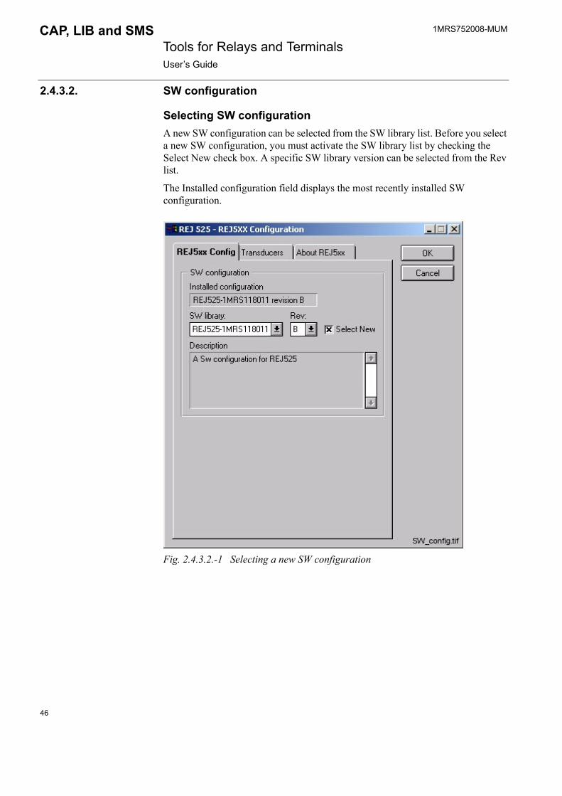
2.4.3.2. SW configuration
Selecting SW configurationA new SW configuration can be selected from the SW library list. Before you select a new SW configuration, you must activate the SW library list by checking the Select New check box. A specific SW library version can be selected from the Rev list.
The Installed configuration field displays the most recently installed SW configuration.
Fig. 2.4.3.2.-1 Selecting a new SW configuration
46

1MRS752008-MUM CAP, LIB and SMS Tools for Relays and TerminalsUser�s Guide
2.4.3.3. Transducer settings
TdSettings
Fig. 2.4.3.3.-1 Giving transducer settings
When the transducer settings are taken out of use, settings in the Relay Tool can be set only by time nominal values (see Fig. 2.4.3.3.-2).
47

1MRS752008-MUM Tools for Relays and TerminalsUser�s Guide
CAP, LIB and SMS
Relay_setting_tool2
Fig. 2.4.3.3.-2 The encapsulated area (primary values) is disabled when there are no transducer settings in use.
2.4.4. REx 61xThis section describes the REx 61x object type and its properties.
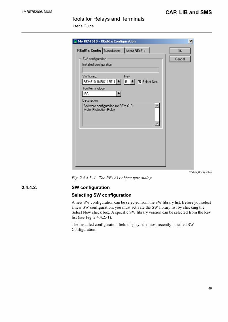
2.4.4.1. GeneralThe REx 61x object type configures object instances for REM 610, REF 610 and REU 610 relays. The software configuration determines which REx 61x relay is being configured. Used function blocks determine the relay functionality. This information is stored in the application configuration.
You can use the REx 61x configuration dialog for selecting the relay unit software and the IEC/ANSI terminology to be used by the tools, and for saving transducer settings (see Fig. 2.4.4.1.-1).
48
1MRS752008-MUM CAP, LIB and SMS Tools for Relays and TerminalsUser�s Guide
REx61x_Configuration
Fig. 2.4.4.1.-1 The REx 61x object type dialog
2.4.4.2. SW configurationSelecting SW configurationA new SW configuration can be selected from the SW library list. Before you select a new SW configuration, you must activate the SW library list by checking the Select New check box. A specific SW library version can be selected from the Rev list (see Fig. 2.4.4.2.-1).
The Installed configuration field displays the most recently installed SW Configuration.
49

1MRS752008-MUM Tools for Relays and TerminalsUser�s Guide
CAP, LIB and SMS
REx61x_Configuration2
Fig. 2.4.4.2.-1 Selecting a new SW configuration
Selecting tool terminologySome REM 610, REF 610 and REU 610 revisions support the selection of the IEC or ANSI terminology to be used by different relay tools. An example of the IEC/ANSI terminology difference is the description for the output state F000O001: IEC = "Thermal Start" and ANSI = "49 Pickup".
The tool terminology selection concerns all the textual parameter names and values, menu texts and event texts visible for example in the Relay Setting Tool and in the Event Editor. It should be noted that this selection does not affect the relay unit in any way, thus is totally independent of the connected relay.
The tool terminology list is activated when a new SW configuration is selected. The choices are dependent on the selected SW library and its version.
50

1MRS752008-MUM CAP, LIB and SMS Tools for Relays and TerminalsUser�s Guide
Tool_terminology
Fig. 2.4.4.2.-2 Selecting tool terminology for a new SW configuration
2.4.4.3. Transducer settingsIf the inputs of the relay are connected to a transducer, instead of having a direct connection to the primary current or voltage, the In Use check box on the Transducer page must be checked. Current primary and secondary currents or voltages must also be defined (see Fig. 2.4.4.3.-1).
51
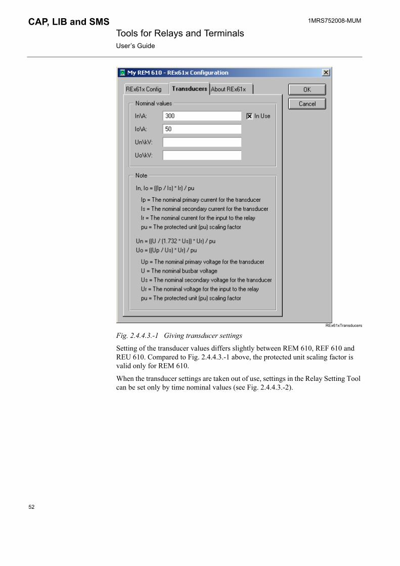
1MRS752008-MUM Tools for Relays and TerminalsUser�s Guide
CAP, LIB and SMS
REx61xTransducers
Fig. 2.4.4.3.-1 Giving transducer settings
Setting of the transducer values differs slightly between REM 610, REF 610 and REU 610. Compared to Fig. 2.4.4.3.-1 above, the protected unit scaling factor is valid only for REM 610.
When the transducer settings are taken out of use, settings in the Relay Setting Tool can be set only by time nominal values (see Fig. 2.4.4.3.-2).
52
1MRS752008-MUM CAP, LIB and SMS Tools for Relays and TerminalsUser�s Guide
REx61x_RelaySettingTool
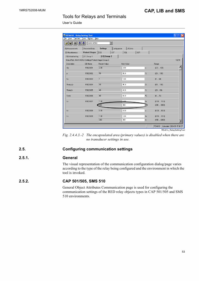
Fig. 2.4.4.3.-2 The encapsulated area (primary values) is disabled when there are no transducer settings in use.
2.5. Configuring communication settings
2.5.1. GeneralThe visual representation of the communication configuration dialog/page varies according to the type of the relay being configured and the environment in which the tool is invoked.
2.5.2. CAP 501/505, SMS 510General Object Attributes Communication page is used for configuring the communication settings of the RED relay objects types in CAP 501/505 and SMS 510 environments.
53

1MRS752008-MUM Tools for Relays and TerminalsUser�s Guide
CAP, LIB and SMS
Fig. 2.5.2.-1 General Object Attributes/Communication page
2.5.2.1. Communication supportTable 2.5.2.1-1 Communication support
LON communicationSelect Card Number, Channel and type in the appropriate values for the Subnet Number, Node Number and SPA address fields. These values should match the respective values assigned to the targeted relay unit.
SPA communicationSelect Serial port and type in the appropriate value for the SPA address field. The value should match the respective value assigned to the targeted relay unit.
REF 54x LON, SPA, SPA TCP/IP
REM 54x LON, SPA, SPA TCP/IP
REC 52x LON, SPA, SPA TCP/IP
RET 54x LON, SPA, SPA TCP/IP
REX 52x LON, SPA, SPA TCP/IP
REJ 5xx SPA, SPA TCP/IP
REU 5xx SPA, SPA TCP/IP
REx 61x SPA, SPA TCP/IP
CAP 501 supports SPA and SPA TCP/IP communication only.
54

1MRS752008-MUM CAP, LIB and SMS Tools for Relays and TerminalsUser�s Guide
SPA TCP/IP communication
Select Local connection and type in the appropriate values for the IP address and SPA address fields. The IP address value should match the respective value assigned to the TCP/IP device between CAP 501/505 and the targeted relay unit. The SPA address value should match the respective value assigned to the targeted relay unit.
2.5.3. LIB 500/510 in MicroSCADAThe CConfig tool is used for setting up the needed communication settings of the RED relay objects types in LIB 500/510 environments. The settings in the dialog may change depending on the type of relay. The following example concerns REF 54x relay.
� The host type can be selected � The station addressing can be configured
IEC_conf
Fig. 2.5.3.-1 CConfig dialog for REF 54x in SYS 500
SMS 510 supports LON and SPA communication only.
Using SPA TCP/IP requires one of the following devices to be connected to CAP 501/505:
- Ethernet adapter SPA-ZC 400/402
- Serial-to-TCP/IP converter
- COM 610 communication gateway
55
1MRS752008-MUM Tools for Relays and TerminalsUser�s Guide
CAP, LIB and SMS
2.5.3.1. Communication supportTable 2.5.3.1-1 Communication support in LIB 500/510
Remark descriptions:
1) IEC 60870-5-101 requires either a COM 6xx or a KU-2000 gateway2) IEC 61850-8 works only with SYS 600 and requires a SPA-ZC 40x communication gateway
AddressesAll the mentioned protocols require an appropriate value to be entered into the "STA number" field. This value must match the respective value assigned to the targeted relay unit in the system configuration.
When using the IEC 60870-5-101 protocol, either the IEC object address (COM 6xx) or the SPA unit number (KU-2000) must also be given. They must match the value configured for the gateway and relay unit in question. With COM 6xx, the master protocol which is used for communication between the relay unit and COM 6xx, must also be defined.
2.6. Application engineering information in LIB 500/510
2.6.1. General
Fig. 2.6.1.-1 Icon for standard function in LIB 500/510
Relay type Protocols Remarks
REF 54x LON, SPA, IEC 60870-5-101, IEC 61850-8 1), 2)
REM 54x LON, SPA, IEC 60870-5-101, IEC 61850-8 1), 2)
REC 52x LON, SPA, IEC 60870-5-101
RET 54x LON, SPA, IEC 60870-5-101, IEC 61850-8 1), 2)
REX 52x LON, SPA, IEC 60870-5-101, IEC 61850-8 1), 2)
REJ 5xx SPA, IEC 61850-8 2)
REU5xx SPA, IEC 61850-8 2)
REx 61x SPA, IEC 61850-8 2)
Table 2.6.1-1 The file names in the package:
File NameFRI_REF54x.DATFRI_REC52x.DATFRI_REM54x.DATFRI_RET54x.DATFRI_REJ5xx.DATFRI_REU5xx.DAFRI_REX52x.DATFRI_REx61x.DAT
56
1MRS752008-MUM CAP, LIB and SMS Tools for Relays and TerminalsUser�s Guide
Table 2.6.1-2 The file locations in the package:
2.6.2. Process objectsThe event process objects of RED relay units can be created with the Event Editor. For detailed information about events, see the CD-ROM �Technical Descriptions of Functions�.
The contents of this paragraph applies only to the LIB 500/510 environment.
The event process objects are created according to the following procedure:
The Event Editor creates the process objects. The Event Editor checks which function blocks are included in the relay unit and presents the events of these function blocks in the Event Editor. In the Editor, you can select which events you want to include in the event reporting and those events to include in both event & alarm reporting.
The events that are masked in the relay settings will not have any corresponding process object. Select only those events of interest, because events that are not important are better not to be mixed with the events of importance, e.g. at some disturbance situation in the supervised process. (See the documentation of the Event Editor in the LIB 510 Configuration Manual).
Each channel (usually one channel corresponds to one function block) reserves 64 indexes from one process object group. This means that one process object group (seen as one logical name) can contain the events of 3 function blocks
Logical names (LN) of the process objects will be:
LIB_OBJECT_NAME + index,where index = character in range A..Z or 0..9, Indexing is done automatically by the Event Editor.
For example, if a user has named the relay as "VAA_H01RE" on the SCT, the logical names of the process objects will be "VAA_H01REA", VAA_H01REB" etc.
2.6.3. FilesThe files that are used for LIB 510 and RED relay types are listed in this paragraph:The contents of this paragraph applies only to the LIB500/510 environment.
File Location in Package
SM_RED/REF54x/INST
SM_RED/REC52x/INST
SM_RED/REM54x/INST
SM_RED/RET54x/INST
SM_RED/REJ5xx/INST
SM_RED/REU5xx/INST
SM_RED/REX52x/INST
SM_RED/REx61x/INST
57

1MRS752008-MUM Tools for Relays and TerminalsUser�s Guide
CAP, LIB and SMS
2.6.3.1. REF 54x
Format picturesFormat pictures used during runtime for event and alarm presentation.
Table 2.6.3.1-1 Format pictures for event and alarm presentation:
*) /SC/LIB4/FMOD/SM_RED/REF54x/
TextsThe text files, used during installation/configuration and runtime, are language dependent.
Table 2.6.3.1-2 Language dependent text files:
*) /SC/LIB4/FMOD/SM_RED/REF54x/ 1)(L = IS A VALUE >=0)
Format pictures and status textsThe following format pictures and status texts (dynamic event texts) are used by the REF 54x object type. You can add new texts into the format text files by using the Event Editor.
File name Name Location *)
FORM4RE3B1.PIC Event texts USE
FORM4RE3B2.PIC Event texts USE
FORM4REDB1.PIC Event texts USE
FORM4REAI1.PIC Event texts USE
FORM4REBI1.PIC Event texts USE
FORM4REPC1.PIC Event texts USE
File name Name Location *)
*.TXT Dynamic event texts LANG�L� 1)
58

1MRS752008-MUM CAP, LIB and SMS Tools for Relays and TerminalsUser�s Guide
Table 2.6.3.1-3 Format pictures and status texts (dynamic event texts) used by the REF 54x object type:
File name Value (OV) Status text
FORM4RE3B1.PIC(object 3bit/AI events)
01234567
Normalon L1on L2on L1 and L2on L3on L3 and L1on L2 and L3on L1,L2 and L3
FORM4RE3B2.PIC(object 3bit/AI events)
01234567
Normalon U12on U23on U12 and U23on U31on U31 and U12on U31 and U23on U12,U23 and U31
FORM4REDB1.PIC(object DB events)
0123
Middle (00)Close (10)Open (01)Faulty (11)
FORM4REAI1.PIC(object AI events)
012345
NormalLow AlarmHigh AlarmLow WarningHigh WarningAlarm/warning limit changed
FORM4REBI1.PIC(object BI events)
01010101010
ResetActivatedOffOnEnabledDisabledInactiveActiveCompletedStartedDeactivated
1010101
ActivatedNormalAlarmNackAckUnsuccessfulUnsuccessful
FORM4REPC1.PIC(object PC events)
01 Updated
59

1MRS752008-MUM Tools for Relays and TerminalsUser�s Guide
CAP, LIB and SMS
2.6.3.2. REC 52x
Format picturesFormat pictures used during runtime for event and alarm presentation.
Table 2.6.3.2-1 Format pictures for event and alarm presentation:
*) /SC/LIB4/FMOD/SM_RED/REC52x/ 1)
TextsThe text files, used during installation/configuration and runtime, are language dependent.
Table 2.6.3.2-2 Language dependent text files used during installation/configuration and runtime:
*) /SC/LIB4/FMOD/SM_RED/REC52x/ 1)(L = IS A VALUE >=0)
Format pictures and status textsThe following format pictures and status texts (dynamic event texts) are used by the REC 52x object type. You can add new texts into the format text files by using the Event Editor.
Table 2.6.3.2-3 Format pictures and status texts (dynamic event texts) used by REC 52x object type:
File name Name Location *)
FORM4RC3B1.PIC Event texts USE 1)
FORM4RC3B2.PIC Event texts USE 1)
FORM4RCDB1.PIC Event texts USE 1)
FORM4RCAI1.PIC Event texts USE 1)
FORM4RCBI1.PIC Event texts USE 1)
FORM4RCPC1.PIC Event texts USE 1)
File name Name Location *)
*.TXT Dynamic event texts LANG�L� 1)
File name Value (OV) Status text
FORM4RC3B1.PIC(object 3bit/AI events)
01234567
Normalon L1on L2on L1 and L2on L3on L3 and L1on L2 and L3on L1,L2 and L3
60

1MRS752008-MUM CAP, LIB and SMS Tools for Relays and TerminalsUser�s Guide
2.6.3.3. REM 54x
Format picturesFormat pictures used during runtime for event and alarm presentation.
Table 2.6.3.3-1 Format pictures for event and alarm presentation:
FORM4RC3B2.PIC(object 3bit/AI events)
01234567
Normalon U12on U23on U12 and U23on U31on U31 and U12on U31 and U23on U12,U23 and U31
FORM4RCDB1.PIC(object DB events)
0123
Middle (00)Close (10)Open (01)Faulty (11)
FORM4RCAI1.PIC(object AI events)
012345
NormalLow AlarmHigh AlarmLow WarningHigh WarningAlarm/warning limit changed
FORM4RCBI1.PIC(object BI events)
010101010101010101
ResetActivatedOffOnEnabledDisabledInactiveActiveCompletedStartedDeactivatedActivatedNormalAlarmNackAckUnsuccessfulUnsuccessful
FORM4RCPC1.PIC(object PC events)
01 Updated
File name Value (OV) Status text
File name Name Location *)
FORM4RM3B1.PIC Event texts USE 1)
FORM4RM3B2.PIC Event texts USE 1)
FORM4RMDB1.PIC Event texts USE 1)
61

1MRS752008-MUM Tools for Relays and TerminalsUser�s Guide
CAP, LIB and SMS
*) /SC/LIB4/FMOD/SM_RED/REM54x/ 1)
TextsThe text files, used during installation/configuration and runtime, are language dependent.
Table 2.6.3.3-2 Language dependent text files used during installation/configuration and runtime:
*) /SC/LIB4/FMOD/SM_RED/REM54x/ 1)(L = IS A VALUE >=0)
Format pictures and status textsThe following format pictures and status texts (dynamic event texts) are used by the REM 54x object type. You can add new texts into the format text files by using the Event Editor.
Table 2.6.3.3-3 Format pictures and status texts (dynamic event texts) used by REM 54x object type:
FORM4RMAI1.PIC Event texts USE 1)
FORM4RMBI1.PIC Event texts USE 1)
FORM4RMPC1.PIC Event texts USE 1)
File name Name Location *)
File name Name Location *)
*.TXT Dynamic event texts LANG�L� 1)
File name Value (OV) Status text
FORM4RM3B1.PIC(object 3bit/AI events)
01234567
Normalon L1on L2on L1 and L2on L3on L3 and L1on L2 and L3on L1,L2 and L3
FORM4RM3B2.PIC(object 3bit/AI events)
01234567
Normalon U12on U23on U12 and U23on U31on U31 and U12on U31 and U23on U12,U23 and U31
FORM4RMDB1.PIC(object DB events)
0123
Middle (00)Close (10)Open (01)Faulty (11)
62
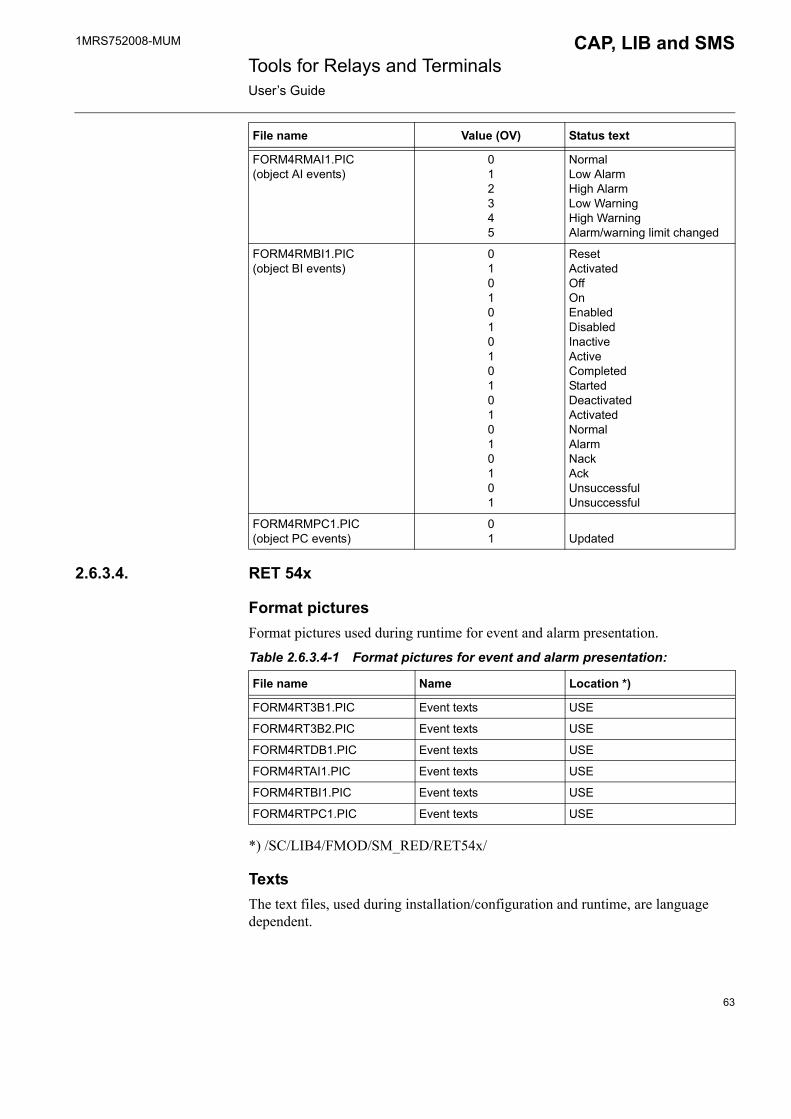
1MRS752008-MUM CAP, LIB and SMS Tools for Relays and TerminalsUser�s Guide
2.6.3.4. RET 54x
Format picturesFormat pictures used during runtime for event and alarm presentation.
Table 2.6.3.4-1 Format pictures for event and alarm presentation:
*) /SC/LIB4/FMOD/SM_RED/RET54x/
TextsThe text files, used during installation/configuration and runtime, are language dependent.
FORM4RMAI1.PIC(object AI events)
012345
NormalLow AlarmHigh AlarmLow WarningHigh WarningAlarm/warning limit changed
FORM4RMBI1.PIC(object BI events)
010101010101010101
ResetActivatedOffOnEnabledDisabledInactiveActiveCompletedStartedDeactivatedActivatedNormalAlarmNackAckUnsuccessfulUnsuccessful
FORM4RMPC1.PIC(object PC events)
01 Updated
File name Value (OV) Status text
File name Name Location *)
FORM4RT3B1.PIC Event texts USE
FORM4RT3B2.PIC Event texts USE
FORM4RTDB1.PIC Event texts USE
FORM4RTAI1.PIC Event texts USE
FORM4RTBI1.PIC Event texts USE
FORM4RTPC1.PIC Event texts USE
63
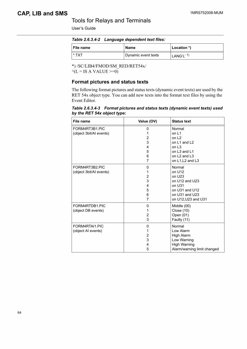
1MRS752008-MUM Tools for Relays and TerminalsUser�s Guide
CAP, LIB and SMS
Table 2.6.3.4-2 Language dependent text files:
*) /SC/LIB4/FMOD/SM_RED/RET54x/ 1)(L = IS A VALUE >=0)
Format pictures and status textsThe following format pictures and status texts (dynamic event texts) are used by the RET 54x object type. You can add new texts into the format text files by using the Event Editor.
Table 2.6.3.4-3 Format pictures and status texts (dynamic event texts) used by the RET 54x object type:
File name Name Location *)
*.TXT Dynamic event texts LANG�L� 1)
File name Value (OV) Status text
FORM4RT3B1.PIC(object 3bit/AI events)
01234567
Normalon L1on L2on L1 and L2on L3on L3 and L1on L2 and L3on L1,L2 and L3
FORM4RT3B2.PIC(object 3bit/AI events)
01234567
Normalon U12on U23on U12 and U23on U31on U31 and U12on U31 and U23on U12,U23 and U31
FORM4RTDB1.PIC(object DB events)
0123
Middle (00)Close (10)Open (01)Faulty (11)
FORM4RTAI1.PIC(object AI events)
012345
NormalLow AlarmHigh AlarmLow WarningHigh WarningAlarm/warning limit changed
64
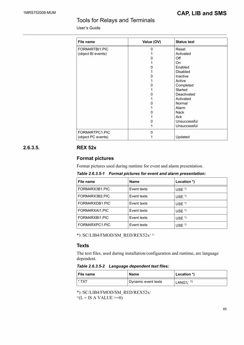
1MRS752008-MUM CAP, LIB and SMS Tools for Relays and TerminalsUser�s Guide
2.6.3.5. REX 52x
Format picturesFormat pictures used during runtime for event and alarm presentation.
Table 2.6.3.5-1 Format pictures for event and alarm presentation:
*) /SC/LIB4/FMOD/SM_RED/REX52x/ 1)
TextsThe text files, used during installation/configuration and runtime, are language dependent.
Table 2.6.3.5-2 Language dependent text files:
*) /SC/LIB4/FMOD/SM_RED/REX52x/ 1)(L = IS A VALUE >=0)
FORM4RTBI1.PIC(object BI events)
010101010101010101
ResetActivatedOffOnEnabledDisabledInactiveActiveCompletedStartedDeactivatedActivatedNormalAlarmNackAckUnsuccessfulUnsuccessful
FORM4RTPC1.PIC(object PC events)
01 Updated
File name Value (OV) Status text
File name Name Location *)
FORM4RX3B1.PIC Event texts USE 1)
FORM4RX3B2.PIC Event texts USE 1)
FORM4RXDB1.PIC Event texts USE 1)
FORM4RXAI1.PIC Event texts USE 1)
FORM4RXBI1.PIC Event texts USE 1)
FORM4RXPC1.PIC Event texts USE 1)
File name Name Location *)
*.TXT Dynamic event texts LANG�L� 1)
65

1MRS752008-MUM Tools for Relays and TerminalsUser�s Guide
CAP, LIB and SMS
Format pictures and status textsThe following format pictures and status texts (dynamic event texts) are used by REX 52x object type. You can add new texts into the format text files by using the Event Editor.
Table 2.6.3.5-3 Format pictures and status texts (dynamic event texts) used by the REX 52x object type:
File name Value (OV) Status text
FORM4RX3B1.PIC(object 3bit/AI events)
01234567
Normalon L1on L2on L1 and L2on L3on L3 and L1on L2 and L3on L1,L2 and L3
FORM4RX3B2.PIC(object 3bit/AI events)
01234567
Normalon U12on U23on U12 and U23on U31on U31 and U12on U31 and U23on U12,U23 and U31
FORM4RXDB1.PIC(object DB events)
0123
Middle (00)Close (10)Open (01)Faulty (11)
FORM4RXAI1.PIC(object AI events)
012345
NormalLow AlarmHigh AlarmLow WarningHigh WarningAlarm/warning limit changed
FORM4RXBI1.PIC(object BI events)
0101010101
ResetActivatedOffOnEnabledDisabledInactiveActiveCompletedStarted
66
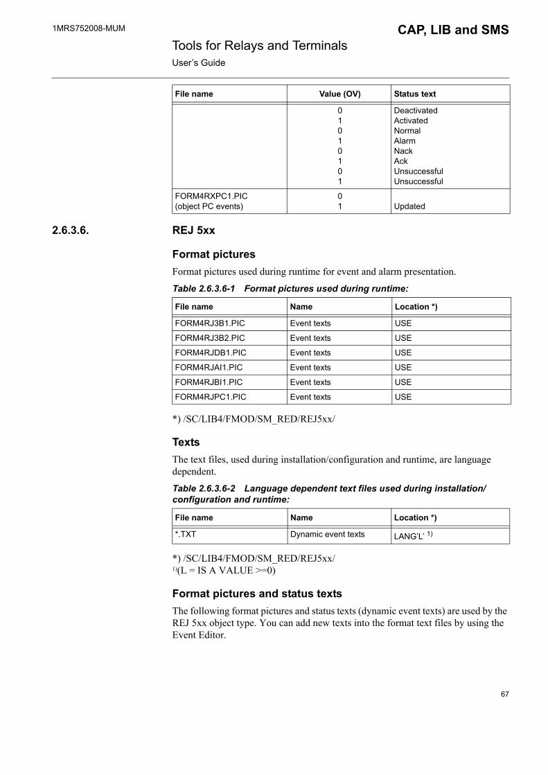
1MRS752008-MUM CAP, LIB and SMS Tools for Relays and TerminalsUser�s Guide
2.6.3.6. REJ 5xx
Format picturesFormat pictures used during runtime for event and alarm presentation.
Table 2.6.3.6-1 Format pictures used during runtime:
*) /SC/LIB4/FMOD/SM_RED/REJ5xx/
TextsThe text files, used during installation/configuration and runtime, are language dependent.
Table 2.6.3.6-2 Language dependent text files used during installation/configuration and runtime:
*) /SC/LIB4/FMOD/SM_RED/REJ5xx/ 1)(L = IS A VALUE >=0)
Format pictures and status textsThe following format pictures and status texts (dynamic event texts) are used by the REJ 5xx object type. You can add new texts into the format text files by using the Event Editor.
01010101
DeactivatedActivatedNormalAlarmNackAckUnsuccessfulUnsuccessful
FORM4RXPC1.PIC(object PC events)
01 Updated
File name Value (OV) Status text
File name Name Location *)
FORM4RJ3B1.PIC Event texts USE
FORM4RJ3B2.PIC Event texts USE
FORM4RJDB1.PIC Event texts USE
FORM4RJAI1.PIC Event texts USE
FORM4RJBI1.PIC Event texts USE
FORM4RJPC1.PIC Event texts USE
File name Name Location *)
*.TXT Dynamic event texts LANG�L� 1)
67

1MRS752008-MUM Tools for Relays and TerminalsUser�s Guide
CAP, LIB and SMS
Table 2.6.3.6-3 Format pictures and status text (dynamic event texts) used by the REJ 5xx object type:
File name Value (OV) Status text
FORM4RJ3B1.PIC(object 3bit/AI events)
01234567
Normalon L1on L2on L1 and L2on L3on L3 and L1on L2 and L3on L1,L2 and L3
FORM4RJ3B2.PIC(object 3bit/AI events)
01234567
Normalon U12on U23on U12 and U23on U31on U31 and U12on U31 and U23on U12,U23 and U31
FORM4RJDB1.PIC(object DB events)
0123
Middle (00)Close (10)Open (01)Faulty (11)
FORM4RJAI1.PIC(object AI events)
012345
NormalLow AlarmHigh AlarmLow WarningHigh WarningAlarm/warning limit changed
FORM4RJBI1.PIC(object BI events)
010101010101010101
ResetActivatedOffOnEnabledDisabledInactiveActiveCompletedStartedDeactivatedActivatedNormalAlarmNackAckUnsuccessfulUnsuccessful
FORM4RJPC1.PIC(object PC events)
01 Updated
68

1MRS752008-MUM CAP, LIB and SMS Tools for Relays and TerminalsUser�s Guide
2.6.3.7. REU 5xx
Format picturesFormat pictures used during runtime for event and alarm presentation.
Table 2.6.3.7-1 Format pictures for event and alarm presentation:
*) /SC/LIB4/FMOD/SM_RED/REU5xx/ 1)
TextsThe text files, used during installation/configuration and runtime, are language dependent.
Table 2.6.3.7-2 Language dependent text files used during installation/configuration and runtime:
*) /SC/LIB4/FMOD/SM_RED/REU5xx/ 1)(L = IS A VALUE >=0)
Format pictures and status textsThe following format pictures and status texts (dynamic event texts) are used by the REU 5xx object type. You can add new texts into the format text files by using the Event Editor.
Table 2.6.3.7-3 Format pictures and status texts (dynamic event texts) used by the REU 5xx object type:
File name Name Location *)
FORM4RU3B1.PIC Event texts USE 1)
FORM4RU3B2.PIC Event texts USE 1)
FORM4RUDB1.PIC Event texts USE 1)
FORM4RUAI1.PIC Event texts USE 1)
FORM4RUBI1.PIC Event texts USE 1)
FORM4RUPC1.PIC Event texts USE 1)
File name Name Location *)
*.TXT Dynamic event texts LANG�L� 1)
File name Value (OV) Status text
FORM4RU3B1.PIC(object 3bit/AI events)
01234567
Normalon L1on L2on L1 and L2on L3on L3 and L1on L2 and L3on L1,L2 and L3
69

1MRS752008-MUM Tools for Relays and TerminalsUser�s Guide
CAP, LIB and SMS
2.6.3.8. REx 61x
Format picturesFormat pictures used during runtime for event and alarm presentation.
Table 2.6.3.8-1 Format pictures used during runtime:
FORM4RU3B2.PIC(object 3bit/AI events)
01234567
Normalon U12on U23on U12 and U23on U31on U31 and U12on U31 and U23on U12,U23 and U31
FORM4RUDB1.PIC(object DB events)
0123
Middle (00)Close (10)Open (01)Faulty (11)
FORM4RUAI1.PIC(object AI events)
012345
NormalLow AlarmHigh AlarmLow WarningHigh WarningAlarm/warning limit changed
FORM4RUBI1.PIC(object BI events)
010101010101010101
ResetActivatedOffOnEnabledDisabledInactiveActiveCompletedStartedDeactivatedActivatedNormalAlarmNackAckUnsuccessfulUnsuccessful
FORM4RUPC1.PIC(object PC events)
01 Updated
File name Value (OV) Status text
File name Name Location *)
FORM4RN3B1.PIC Event texts USE 1)
FORM4RN3B2.PIC Event texts USE 1)
FORM4RNAI1.PIC Event texts USE 1)
70

1MRS752008-MUM CAP, LIB and SMS Tools for Relays and TerminalsUser�s Guide
*) /SC/LIB4/FMOD/SM_RED/REx61x/ 1)
TextsThe text files, used during installation/configuration and runtime, are language dependent.
Table 2.6.3.8-2 Language dependent text files used during installation/configuration and runtime:
*) /SC/LIB4/FMOD/SM_RED/REx61x/ 1) (L = IS A VALUE >=0)
Format pictures and status textsThe following format pictures and status texts (dynamic event texts) are used by the REx 61x object type. You can add new texts into the format text files by using the Event Editor.
Table 2.6.3.8-3 Format pictures and status text (dynamic event texts) used by the REx 61x object type:
FORM4RNBI1.PIC Event texts USE 1)
FORM4RNDB1.PIC Event texts USE 1)
FORM4RNPC1.PIC Event texts USE 1)
File name Name Location *)
File name Name Location *)
*.TXT Dynamic event texts LANG�L� 1)
File name Value (OV) Status text
FORM4RN3B1.PIC(object 3bit/AI events)
01234567
Normalon L1on L2on L1 and L2on L3on L3 and L1on L2 and L3on L1, L2 and L3
FORM4RN3B2.PIC(object 3bit/AI events)
01234567
Normalon U12on U23on U12 and U23on U31on U31 and U12on U31 and U23on U12, U23 and U31
FORM4RNAI1.PIC(object AI events)
012345
NormalLow AlarmHigh AlarmLow WarningHigh WarningAlarm/warning limit changed
71

1MRS752008-MUM Tools for Relays and TerminalsUser�s Guide
CAP, LIB and SMS
FORM4RNBI1.PIC(object BI events)
010101010101010
ResetActivatedOffOnEnabledDisabledInactiveActiveCompletedStartedDeactivatedActivatedNormalAlarmNack
101
AckUnsuccessfulUnsuccessful
FORM4RNDB1.PIC(object DB events)
0123
Middle (00)Close (10)Open (01)Faulty (11)
FORM4RNPC1.PIC(object PC events)
01 Updated
File name Value (OV) Status text
72

1MRS752008-MUM CAP, LIB and SMS Tools for Relays and TerminalsUser�s Guide
3. SPACOM relay object types
3.1. Overview
3.1.1. DescriptionAn object type is a package that contains relay configuration descriptions, profile files, standard function pictures and data files, format pictures and texts.
SPACOM relay object type package is used in the CAP 501 Relay Setting Tools, CAP 505 Relay Product Engineering Tools, SMS 510 Substation Monitoring System and MicroSCADA application libraries LIB 500/510.
3.1.2. Communication support
*) IEC 61850-8 supported only with SYS 600
3.2. Basic concepts/terminologyIf you are unfamiliar with the basic concepts and terminology, such as object types, object type groups or projects, see Section 2.3.
3.3. Installation and configuration
3.3.1. LIB 510/MicroSCADA: installing and configuring SPACOM relays picture functionsIn LIB/MicroSCADA environment, the standard function of SPACOM is presented with the following icon:
Fig. 3.3.1.-1 Standard Function icon
File name: FRI_SPASM.DATFile location in package: SM_SPACOM/SPACOM/INST
Following steps and tools are required for a SPACOM relay picture function in MicroSCADA:
1. Installation of the relay picture function (Installation Tool)2. Configuration of the relay picture function (Standard Configuration Tool)
Table 3.1.2-1 Supported communication protocols:
Product ProtocolCAP 501 SPA, SPA TCP/IPCAP 505 SPA, SPA TCP/IPSMS 510 SPALIB 500/510 SPA, ANSI via SRIO, RP570 via REC200,
RP571 via RTU2x0, IEC 60870-5-101 via COM 6xx, IEC 60870-5-101 via KU-2000, IEC 61850-8 via SPA-ZC 40x *)
73
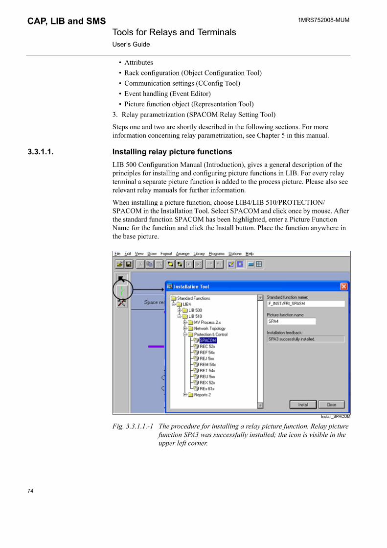
1MRS752008-MUM Tools for Relays and TerminalsUser�s Guide
CAP, LIB and SMS
� Attributes � Rack configuration (Object Configuration Tool)� Communication settings (CConfig Tool)� Event handling (Event Editor)� Picture function object (Representation Tool)
3. Relay parametrization (SPACOM Relay Setting Tool)
Steps one and two are shortly described in the following sections. For more information concerning relay parametrization, see Chapter 5 in this manual.
3.3.1.1. Installing relay picture functionsLIB 500 Configuration Manual (Introduction), gives a general description of the principles for installing and configuring picture functions in LIB. For every relay terminal a separate picture function is added to the process picture. Please also see relevant relay manuals for further information.
When installing a picture function, choose LIB4/LIB 510/PROTECTION/SPACOM in the Installation Tool. Select SPACOM and click once by mouse. After the standard function SPACOM has been highlighted, enter a Picture Function Name for the function and click the Install button. Place the function anywhere in the base picture.
Install_SPACOM
Fig. 3.3.1.1.-1 The procedure for installing a relay picture function. Relay picture function SPA3 was successfully installed; the icon is visible in the upper left corner.
74

1MRS752008-MUM CAP, LIB and SMS Tools for Relays and TerminalsUser�s Guide
3.3.1.2. Relay picture function configurationThe following flowchart shows the procedure of the relay configuration:
Fig. 3.3.1.2.-1 The procedure of the relay configuration
The Object Configuration tool is opened from the Tools menu of the Standard Configuration Tool. The configuration of the relay can be divided into three phases.
1. Rack and module configuration2. Storing relay specific data to the database3. Storing picture function data
Phases 1 and 2 are done within the Object Configuration Tool.
Phase 3, storing picture function data, is done using the Standard Configuration Tool by selecting Apply or Save.
3.3.1.3. Standard Configuration Tool functionsThe pages Attributes and Tools are described in this section. The Representation Tool in the Tools menu is not described.
Select the relay picture function and start the Standard Configuration Tool. Now you can modify the configurable attributes and to start the Object Configuration Tool.
Before starting the configuration, ensure that the base system objects concerning the stations and nodes are configured correctly.
75
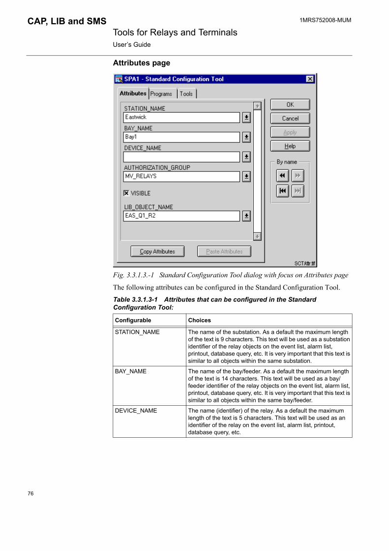
1MRS752008-MUM Tools for Relays and TerminalsUser�s Guide
CAP, LIB and SMS
Attributes page
Fig. 3.3.1.3.-1 Standard Configuration Tool dialog with focus on Attributes page
The following attributes can be configured in the Standard Configuration Tool.
Table 3.3.1.3-1 Attributes that can be configured in the Standard Configuration Tool:
Configurable Choices
STATION_NAME The name of the substation. As a default the maximum length of the text is 9 characters. This text will be used as a substation identifier of the relay objects on the event list, alarm list, printout, database query, etc. It is very important that this text is similar to all objects within the same substation.
BAY_NAME The name of the bay/feeder. As a default the maximum length of the text is 14 characters. This text will be used as a bay/feeder identifier of the relay objects on the event list, alarm list, printout, database query, etc. It is very important that this text is similar to all objects within the same bay/feeder.
DEVICE_NAME The name (identifier) of the relay. As a default the maximum length of the text is 5 characters. This text will be used as an identifier of the relay on the event list, alarm list, printout, database query, etc.
76

1MRS752008-MUM CAP, LIB and SMS Tools for Relays and TerminalsUser�s Guide
Saving relay data to the picture functionAfter the relay has been configured using the relay configuration tools, the data has to be saved to the picture function. Save the data by using the Standard Configuration Tool commands Save or Apply.
Copying picture function dataTo copy picture function data and to paste it into another picture function, use the commands Copy attributes and Paste attributes of the Standard Configuration Tool. After you have copied the picture function data, open the Object Configuration Tool and make the necessary definitions (addresses etc.).
Deleting picture functionsPicture functions that have no connections to databases can be deleted directly in the Picture Editor. To delete a picture function element:
� Select the element with the selector
� Then click at the border of the element.� Choose Delete in the Edit menu and the element disappears. This can also be
done by pressing Delete on the keyboard.
Tools pageThe following tools can be started from the Tools page in the Standard Configuration Tool (see Fig. 3.3.1.3.-2):
� Object Configuration Tool for rack configuration (Function is described in a later section).
� CConfig Tool for communication settings (Function is described in a later section).
� Event Editor for event handling (Function is described in the LIB 510 Configuration Manual).
� Representation Tool for picture function symbol used for the relay object, not described.
AUTHORIZATION GROUP
The authorization group used for the object.
VISIBLE Visibility of the object.
LIB_OBJECT_NAME Identifies the relay object. Name should be unique within the application. The logical names of event process objects will be created by using this name:LN = LIB_OBJECT_NAME + GT specific character. (GT specific character is defined by LIB500 installation tools.) Max. length of attribute: 9 characters.
Configurable Choices
77

1MRS752008-MUM Tools for Relays and TerminalsUser�s Guide
CAP, LIB and SMS
Fig. 3.3.1.3.-2 The Standard Configuration Tool dialog - Tools page
3.3.1.4. Relay parametrizationAfter the Relay picture function has been configured, you can set the relay module parameters with the SPACOM Relay Setting Tool. For more information, see Chapter 4 in this manual.
3.3.2. CAP 501/505 and SMS 510In CAP 501/505 and SMS 510 environments, start the Object Configuration Tool by clicking first the Object Properties shortcut button in the toolbar. Then click the Attributes button in the General Object Attributes dialog.
3.3.3. Object Configuration Tool dialogRack configuration and transducers are defined in the Object type configuration dialog, see the following sections.
3.3.3.1. Rack configuration pageBy clicking the Attributes button in the General Object Attributes dialog, the configuration dialog containing three tabbed pages appears on the screen (see Fig. 3.3.3.1.-1).
78
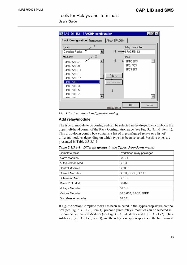
1MRS752008-MUM CAP, LIB and SMS Tools for Relays and TerminalsUser�s Guide
Fig. 3.3.3.1.-1 Rack Configuration dialog
Add relay/moduleThe type of module to be configured can be selected in the drop-down combo in the upper left-hand corner of the Rack Configuration page (see Fig. 3.3.3.1.-1, item 1). This drop-down combo box contains a list of preconfigured relays or a list of different modules depending on which type has been selected. Possible types are presented in Table 3.3.3.1-1.
Table 3.3.3.1-1 Different groups in the Types drop-down menu:
If e.g. the option Complete racks has been selected in the Types drop-down combo box (see Fig. 3.3.3.1.-1, item 1), preconfigured relays /modules can be selected in the combo box named Modules (see Fig. 3.3.3.1.-1, item 2 and Fig. 3.3.3.1.-2). Click Add (see Fig. 3.3.3.1.-1, item 3), and the relay description appears in the field named
Complete racks Predefined relay packages
Alarm Modules SACO
Auto Reclose Mod. SPCT
Control Modules SPTO
Current Modules SPCJ, SPCS, SPCP
Differential Mod. SPCD
Motor Prot. Mod. SPAM
Voltage Modules SPCU
Various Modules SPC 000, SPCF, SPEF
Disturbance recorder SPCR
79

1MRS752008-MUM Tools for Relays and TerminalsUser�s Guide
CAP, LIB and SMS
Relay Description in the upper right-hand corner (see Fig. 3.3.3.1.-1, item 4). A list of corresponding modules is presented in the combo box named Rack (see Fig. 3.3.3.1.-1, item 5).
If the Rack combo box (see Fig. 3.3.3.1.-1, item 5) contains modules, the Relay Description field (item 4) is empty. If, in turn, you have selected the option Complete Racks, the name of the relay will automatically turn up in the Relay Description field. After the rack has been configured, it is always possible to enter a description manually into the Relay Description field.
In case modules need to be removed, click the Remove button. Click OK to execute the operation. If you wish to cancel the operation, click Cancel.
Fig. 3.3.3.1.-2 Selection of the Complete racks. The rest of the modules can be scrolled.
3.3.3.2. Transducers page
Fig. 3.3.3.2.-1 Transducers dialog
80
1MRS752008-MUM CAP, LIB and SMS Tools for Relays and TerminalsUser�s Guide
Nominal Values can be entered (and altered) in the fields on the Transducers page (see Fig. 3.3.3.2.-1). To exit the dialog, click OK. The operation may be cancelled by clicking Cancel.
Nominal values fields:
The nominal values fields represent the nominal values of the transducers of the module.
The nominal values are calculated according to the following rules:
Currents (I, I0):
Ip = The nominal primary current for the transducer
Is = The nominal secondary current for the transducer
Ir = The nominal current for the input to the SPA relay
Residual voltage (U0):
or, if using the busbar voltage
Up = The nominal primary voltage for the transducer
U = The nominal busbar voltage
Us = The nominal secondary voltage for the transducer
Ur = The nominal voltage for the input to the SPA relay
Nominal value IpIs----- Ir×=
Nominal value UpUs------- Ur×=
Nominal value U1 732 Us×,---------------------------- Ur×=
81

1MRS752008-MUM Tools for Relays and TerminalsUser�s Guide
CAP, LIB and SMS
Example:
The "nominal" value to be invoked is:
3.3.4. Communication configurationIn order for the relay to communicate with the relay tools, communication between them has to be configured. This is performed in different ways in LIB and in CAP environments (see the following sections).
3.3.4.1. LIB 510 in MicroSCADA
Fig. 3.3.4.1.-1 Standard Configuration Tool - Starting CConfig Tool
To start the Cconfig Tool in the Standard Configuration Tool/Tools page, double-click Cconfig Tool, or activate the name and click Open.
Nominal value 300A5A
------------- 5A 300=×=
82

1MRS752008-MUM CAP, LIB and SMS Tools for Relays and TerminalsUser�s Guide
Protocol page
Fig. 3.3.4.1.-2 The Protocol page
The available protocols are shown on the first page named Protocol (see Fig. 3.3.4.1.-2).
Address Settings page
Fig. 3.3.4.1.-3 Address Settings page
On the second page named Address Settings (see Fig. 3.3.4.1.-3) it is possible to select the installed modules in the combo box. The Unit number of the Module addresses can be entered in the Sta Nr -field on the lower part of the page.
83
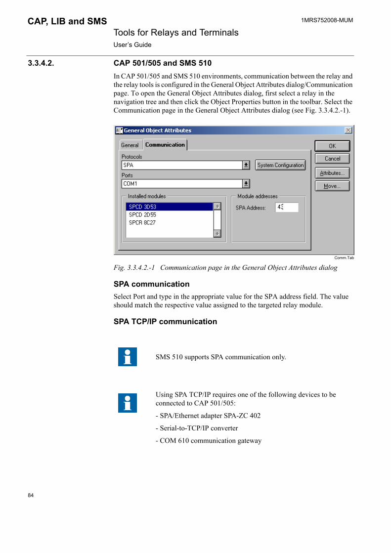
1MRS752008-MUM Tools for Relays and TerminalsUser�s Guide
CAP, LIB and SMS
3.3.4.2. CAP 501/505 and SMS 510In CAP 501/505 and SMS 510 environments, communication between the relay and the relay tools is configured in the General Object Attributes dialog/Communication page. To open the General Object Attributes dialog, first select a relay in the navigation tree and then click the Object Properties button in the toolbar. Select the Communication page in the General Object Attributes dialog (see Fig. 3.3.4.2.-1).
Comm.Tab
Fig. 3.3.4.2.-1 Communication page in the General Object Attributes dialog
SPA communicationSelect Port and type in the appropriate value for the SPA address field. The value should match the respective value assigned to the targeted relay module.
SPA TCP/IP communication
SMS 510 supports SPA communication only.
Using SPA TCP/IP requires one of the following devices to be connected to CAP 501/505:
- SPA/Ethernet adapter SPA-ZC 402
- Serial-to-TCP/IP converter
- COM 610 communication gateway
84

1MRS752008-MUM CAP, LIB and SMS Tools for Relays and TerminalsUser�s Guide
Select TCP port and type in the appropriate values for the IP address and SPA address fields. The IP address value should match the respective value assigned to the TCP/IP device between CAP 501/505 and the targeted relay unit. The SPA address value should match the respective value assigned to the targeted relay module.
3.4. Application engineering information in LIB 510/MicroSCADAThe contents of this section concern only LIB 510/MicroSCADA environment.
3.4.1. Process objectsThe process objects in SPACOM are described in Section 3.4.3.
3.4.2. FilesThe files that are used for LIB 510 SPACOM are described below.
3.4.2.1. Format picturesFormat pictures used during runtime for event and alarm presentation (see Table 3.4.2.1-1).
Table 3.4.2.1-1 Format pictures used for event and alarm presentation:
*) SC/LIB4/FMOD/SM_SPACOM/SPACOM/ 1)
3.4.2.2. TextsLanguage dependent text files are used during installation/configuration and runtime.
Table 3.4.2.2-1 Language dependent text files used during installation/configuration and runtime:
*) SC/LIB4/FMOD/SM_SPACOM/ SPACOM/ 1)(L = IS A VALUE >=0)
3.4.3. Process objectsProcess objects are created in the Event Editor. Event codes, Object texts and indexes are shown in Table 3.4.3.2-1 - Table 3.4.3.49-1.
Filename Name Location *)
FORM4FRALI.PIC Event texts USE 1)
FORM4UMEV.PIC Unmapped events USE 1)
Filename Name Location *)
*.TXT Event texts LANG�L� 1)
*.SPT Group texts LANG�L� 1)
*.CFG Relay unit texts LANG�L� 1)
85

1MRS752008-MUM Tools for Relays and TerminalsUser�s Guide
CAP, LIB and SMS
3.4.3.1. Used abbreviationsTable 3.4.3.1-1 Used abbreviations:
ACT. ACTIVATION
AR AUTORECLOSE
BLK. BLOCK
BS BLOCKING SIGNAL
C CLOSE
CB CIRCUIT BREAKER
CH CHANNEL
COM. COMMAND
CS COMMAND SIGNAL
DEF. DEFINITE
DEL. DELAYED
DEVI. DEVIATION
DISC. DISCONNECTOR
DISCON. DISCONNECTOR
DWNW DOWNWARD
E/F EARTH FAULT
EXT. EXTERNAL
H-SET HI-SET
HSAR HI-SPEED AUTORECLOSE
IND. INDICATION
INHIB. INHIBIT
INIT. INITIALIZATION
INT. INTERNAL
INTER. INTERRUPTED
L-SET LO-SET
L/R LOCAL/REMOTE
MEAS. MEASUREMENT
MEM. MEMORY
O OPEN
OSC. OSCILLATION
OVERL. OVERLOAD
O/C OVERCURRENT
PARAM. PARAMETER
PROTEC. PROTECTION
RECONN. RECONNECTION
REG. REGISTER
REV. REVERSE
SC SYNCROCHECK
86
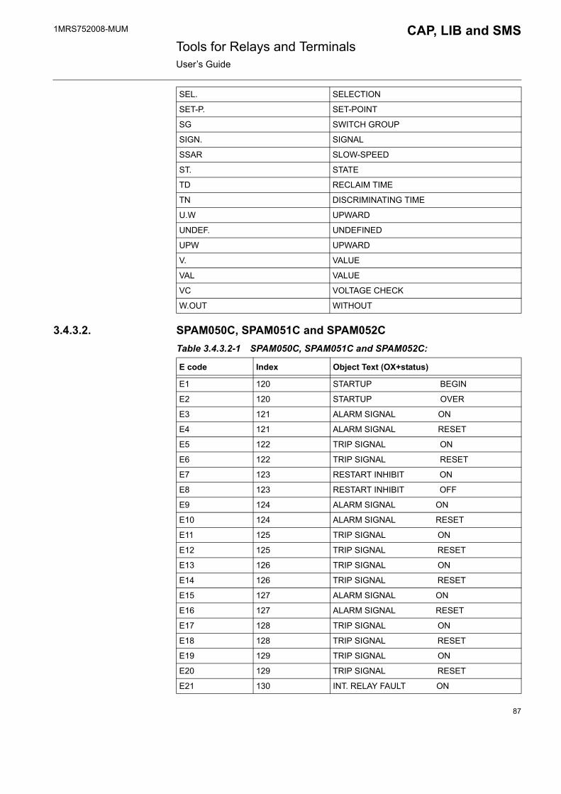
1MRS752008-MUM CAP, LIB and SMS Tools for Relays and TerminalsUser�s Guide
3.4.3.2. SPAM050C, SPAM051C and SPAM052CTable 3.4.3.2-1 SPAM050C, SPAM051C and SPAM052C:
SEL. SELECTION
SET-P. SET-POINT
SG SWITCH GROUP
SIGN. SIGNAL
SSAR SLOW-SPEED
ST. STATE
TD RECLAIM TIME
TN DISCRIMINATING TIME
U.W UPWARD
UNDEF. UNDEFINED
UPW UPWARD
V. VALUE
VAL VALUE
VC VOLTAGE CHECK
W.OUT WITHOUT
E code Index Object Text (OX+status)
E1 120 STARTUP BEGIN
E2 120 STARTUP OVER
E3 121 ALARM SIGNAL ON
E4 121 ALARM SIGNAL RESET
E5 122 TRIP SIGNAL ON
E6 122 TRIP SIGNAL RESET
E7 123 RESTART INHIBIT ON
E8 123 RESTART INHIBIT OFF
E9 124 ALARM SIGNAL ON
E10 124 ALARM SIGNAL RESET
E11 125 TRIP SIGNAL ON
E12 125 TRIP SIGNAL RESET
E13 126 TRIP SIGNAL ON
E14 126 TRIP SIGNAL RESET
E15 127 ALARM SIGNAL ON
E16 127 ALARM SIGNAL RESET
E17 128 TRIP SIGNAL ON
E18 128 TRIP SIGNAL RESET
E19 129 TRIP SIGNAL ON
E20 129 TRIP SIGNAL RESET
E21 130 INT. RELAY FAULT ON
87

1MRS752008-MUM Tools for Relays and TerminalsUser�s Guide
CAP, LIB and SMS
3.4.3.3. SPCD3C21Table 3.4.3.3-1 SPCD3C21:
3.4.3.4. SPCD3C22Table 3.4.3.4-1 SPCD3C22:
3.4.3.5. SPCD3C23Table 3.4.3.5-1 SPCD3C23:
E22 130 INT. RELAY FAULT OFF
E50 202 RESTARTING
E51 203 REG. OVERFLOW
E52 204 COMMUNICATION
E53 205 RESPONDS FAILED
E54 205 RESPONDS AGAIN
E code Index Object Text
E1 31 HARMONICS BLOCKING ON
E2 31 HARMONICS BLOCKING OFF
E3 32 L1 TRIP ON
E4 32 L1 TRIP OFF
E50 180 RESTARTING
E51 181 REG. OVERFLOW
E52 182 COMMUNICATION
E53 183 RESPONDS FAILED
E54 183 RESPONDS AGAIN
E code Index Object Text
E1 33 HARMONICS BLOCKING ON
E2 33 HARMONICS BLOCKING OFF
E3 34 L2 TRIP ON
E4 34 L2 TRIP OFF
E50 184 RESTARTING
E51 185 REG. OVERFLOW
E52 186 COMMUNICATION
E53 187 RESPONDS FAILED
E54 187 RESPONDS AGAIN
E code Index Object Text
E1 35 HARMONICS BLOCKING ON
E2 35 HARMONICS BLOCKING OFF
E3 36 L3 TRIP ON
88

1MRS752008-MUM CAP, LIB and SMS Tools for Relays and TerminalsUser�s Guide
3.4.3.6. SPCJ1C20Table 3.4.3.6-1 SPCJ1C20:
3.4.3.7. SPCJ1C7Table 3.4.3.7-1 SPCJ1C7:
E4 36 L3 TRIP OFF
E50 188 RESTARTING
E51 189 REG. OVERFLOW
E52 190 COMMUNICATION
E53 191 RESPONDS FAILED
E54 191 RESPONDS AGAIN
E code Index Object Text
E code Index Object Text
E1 26 I1F> START ON
E2 26 I1F> START OFF
E3 27 BLOCKING ON
E4 27 BLOCKING OFF
E50 196 RESTARTING
E51 197 REG. OVERFLOW
E52 198 COMMUNICATION
E53 199 RESPONDS FAILED
E54 199 RESPONDS AGAIN
E code Index Object Text
E1 11 I0> START ON
E2 11 I0> START OFF
E3 12 I0> TRIP ON
E4 12 I0> TRIP OFF
E5 13 I0>> START ON
E6 13 I0>> START OFF
E7 14 I0>> TRIP ON
E8 14 I0>> TRIP OFF
E50 180 RESTARTING
E51 181 REG. OVERFLOW
E52 182 COMMUNICATION
E53 183 RESPONDS FAILED
E54 183 RESPONDS AGAIN
89
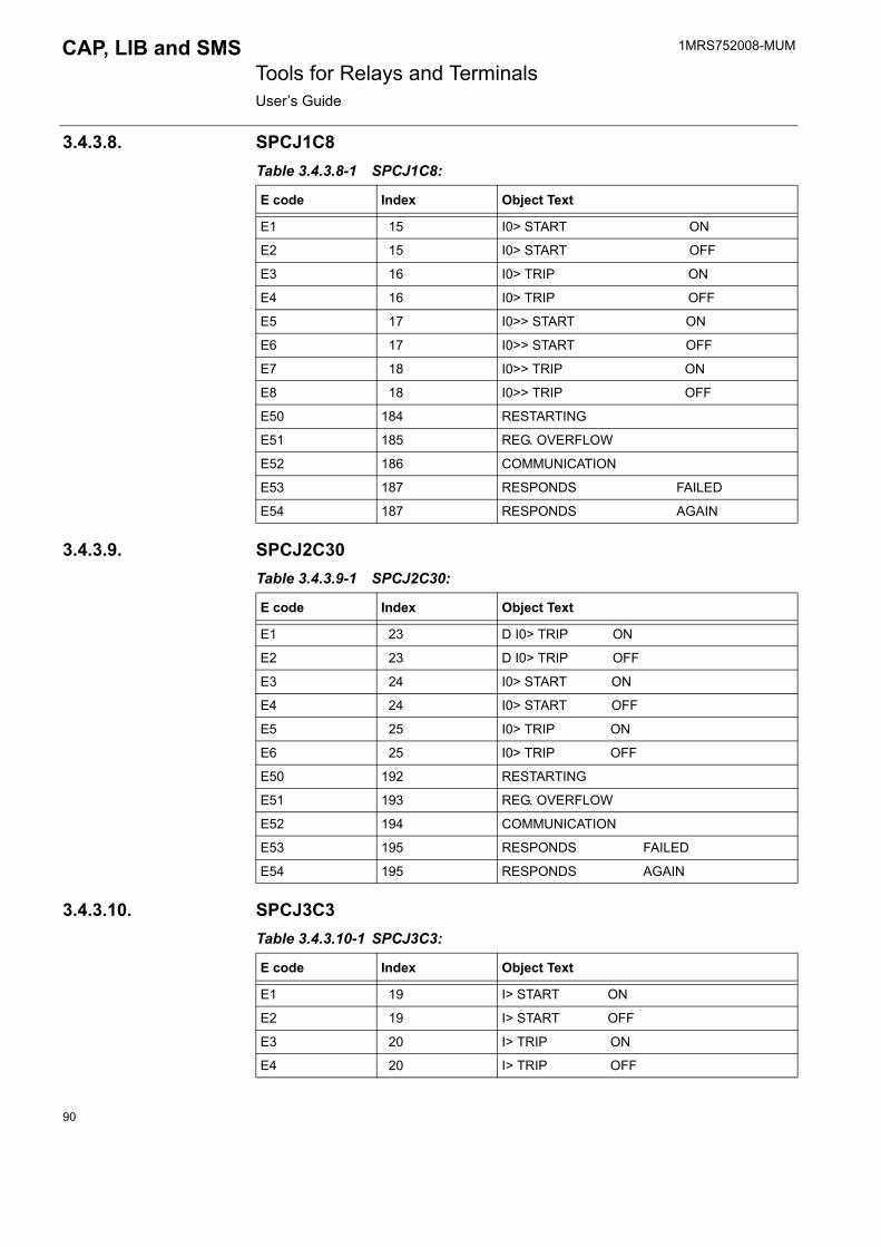
1MRS752008-MUM Tools for Relays and TerminalsUser�s Guide
CAP, LIB and SMS
3.4.3.8. SPCJ1C8Table 3.4.3.8-1 SPCJ1C8:
3.4.3.9. SPCJ2C30Table 3.4.3.9-1 SPCJ2C30:
3.4.3.10. SPCJ3C3Table 3.4.3.10-1 SPCJ3C3:
E code Index Object Text
E1 15 I0> START ON
E2 15 I0> START OFF
E3 16 I0> TRIP ON
E4 16 I0> TRIP OFF
E5 17 I0>> START ON
E6 17 I0>> START OFF
E7 18 I0>> TRIP ON
E8 18 I0>> TRIP OFF
E50 184 RESTARTING
E51 185 REG. OVERFLOW
E52 186 COMMUNICATION
E53 187 RESPONDS FAILED
E54 187 RESPONDS AGAIN
E code Index Object Text
E1 23 D I0> TRIP ON
E2 23 D I0> TRIP OFF
E3 24 I0> START ON
E4 24 I0> START OFF
E5 25 I0> TRIP ON
E6 25 I0> TRIP OFF
E50 192 RESTARTING
E51 193 REG. OVERFLOW
E52 194 COMMUNICATION
E53 195 RESPONDS FAILED
E54 195 RESPONDS AGAIN
E code Index Object Text
E1 19 I> START ON
E2 19 I> START OFF
E3 20 I> TRIP ON
E4 20 I> TRIP OFF
90
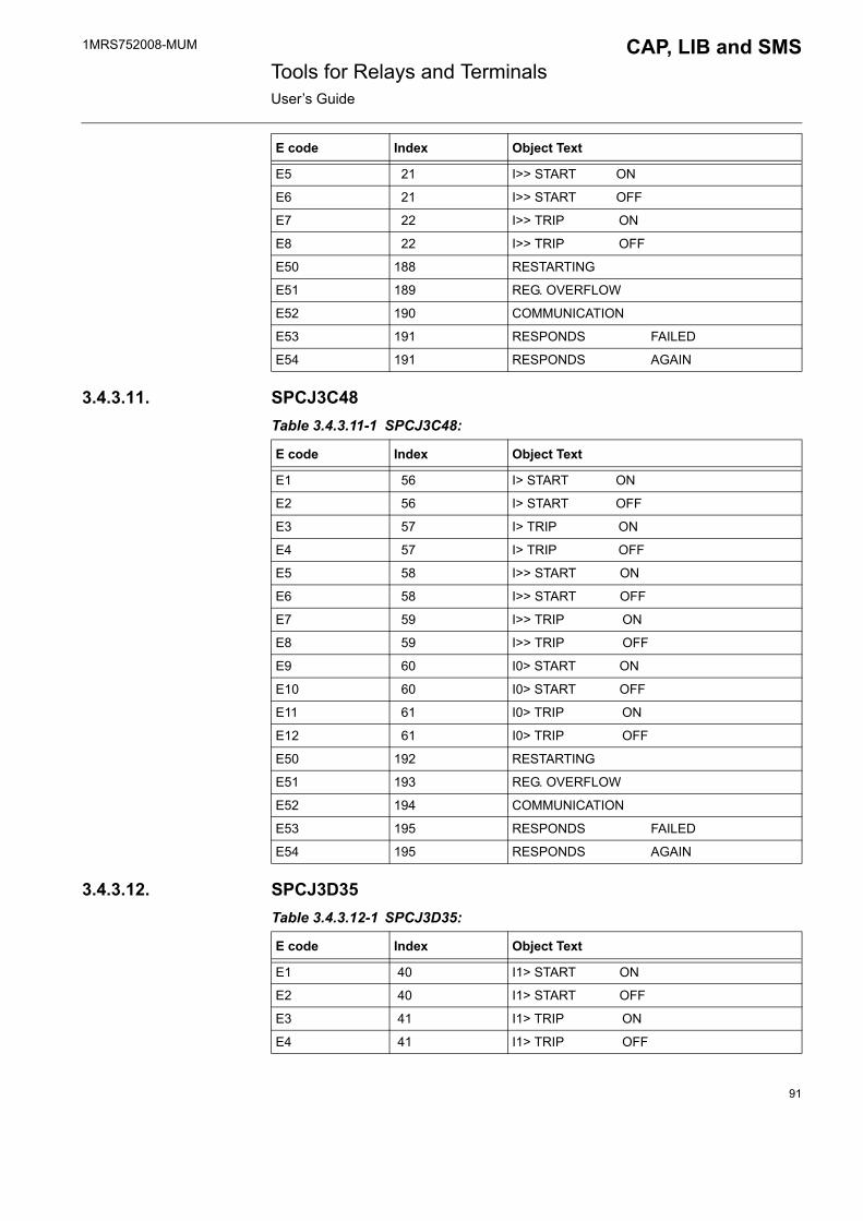
1MRS752008-MUM CAP, LIB and SMS Tools for Relays and TerminalsUser�s Guide
3.4.3.11. SPCJ3C48Table 3.4.3.11-1 SPCJ3C48:
3.4.3.12. SPCJ3D35Table 3.4.3.12-1 SPCJ3D35:
E5 21 I>> START ON
E6 21 I>> START OFF
E7 22 I>> TRIP ON
E8 22 I>> TRIP OFF
E50 188 RESTARTING
E51 189 REG. OVERFLOW
E52 190 COMMUNICATION
E53 191 RESPONDS FAILED
E54 191 RESPONDS AGAIN
E code Index Object Text
E code Index Object Text
E1 56 I> START ON
E2 56 I> START OFF
E3 57 I> TRIP ON
E4 57 I> TRIP OFF
E5 58 I>> START ON
E6 58 I>> START OFF
E7 59 I>> TRIP ON
E8 59 I>> TRIP OFF
E9 60 I0> START ON
E10 60 I0> START OFF
E11 61 I0> TRIP ON
E12 61 I0> TRIP OFF
E50 192 RESTARTING
E51 193 REG. OVERFLOW
E52 194 COMMUNICATION
E53 195 RESPONDS FAILED
E54 195 RESPONDS AGAIN
E code Index Object Text
E1 40 I1> START ON
E2 40 I1> START OFF
E3 41 I1> TRIP ON
E4 41 I1> TRIP OFF
91
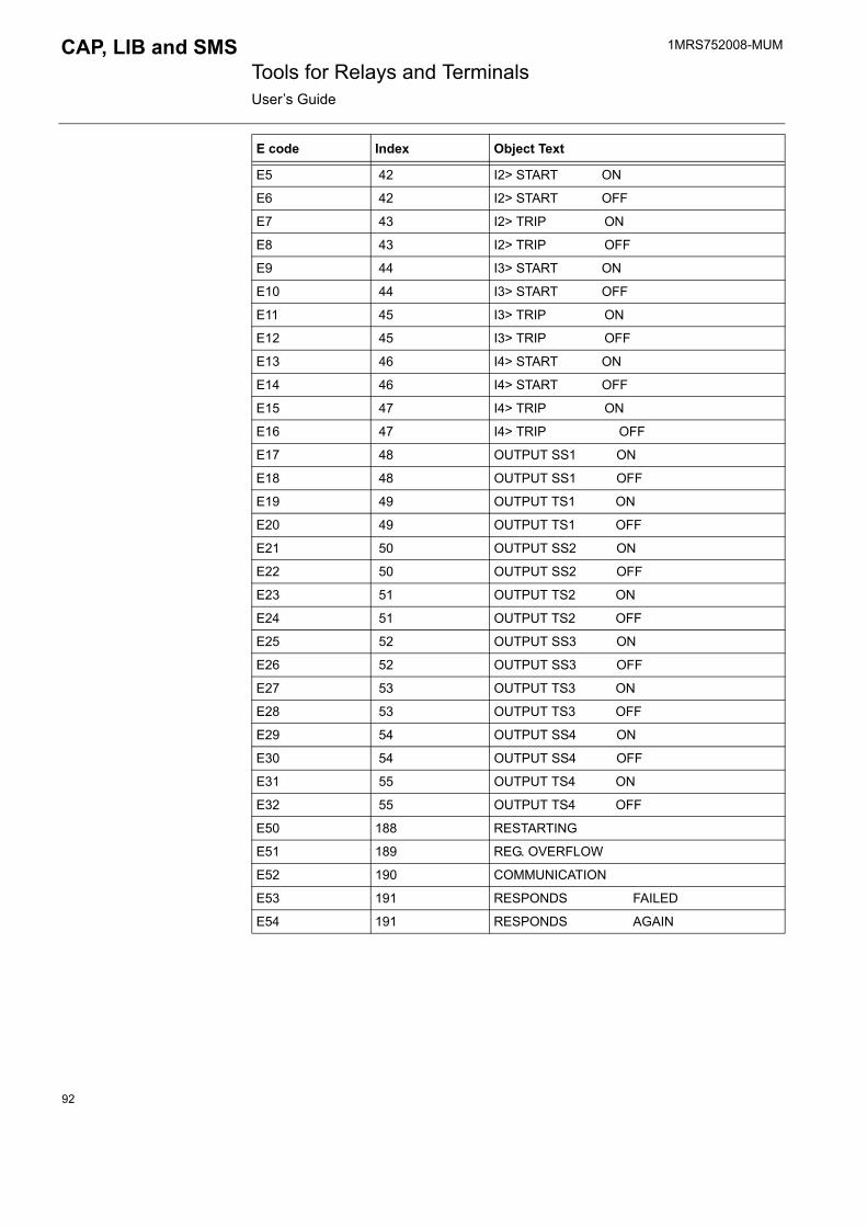
1MRS752008-MUM Tools for Relays and TerminalsUser�s Guide
CAP, LIB and SMS
E5 42 I2> START ON
E6 42 I2> START OFF
E7 43 I2> TRIP ON
E8 43 I2> TRIP OFF
E9 44 I3> START ON
E10 44 I3> START OFF
E11 45 I3> TRIP ON
E12 45 I3> TRIP OFF
E13 46 I4> START ON
E14 46 I4> START OFF
E15 47 I4> TRIP ON
E16 47 I4> TRIP OFF
E17 48 OUTPUT SS1 ON
E18 48 OUTPUT SS1 OFF
E19 49 OUTPUT TS1 ON
E20 49 OUTPUT TS1 OFF
E21 50 OUTPUT SS2 ON
E22 50 OUTPUT SS2 OFF
E23 51 OUTPUT TS2 ON
E24 51 OUTPUT TS2 OFF
E25 52 OUTPUT SS3 ON
E26 52 OUTPUT SS3 OFF
E27 53 OUTPUT TS3 ON
E28 53 OUTPUT TS3 OFF
E29 54 OUTPUT SS4 ON
E30 54 OUTPUT SS4 OFF
E31 55 OUTPUT TS4 ON
E32 55 OUTPUT TS4 OFF
E50 188 RESTARTING
E51 189 REG. OVERFLOW
E52 190 COMMUNICATION
E53 191 RESPONDS FAILED
E54 191 RESPONDS AGAIN
E code Index Object Text
92
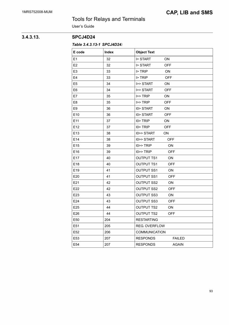
1MRS752008-MUM CAP, LIB and SMS Tools for Relays and TerminalsUser�s Guide
3.4.3.13. SPCJ4D24Table 3.4.3.13-1 SPCJ4D24:
E code Index Object Text
E1 32 I> START ON
E2 32 I> START OFF
E3 33 I> TRIP ON
E4 33 I> TRIP OFF
E5 34 I>> START ON
E6 34 I>> START OFF
E7 35 I>> TRIP ON
E8 35 I>> TRIP OFF
E9 36 I0> START ON
E10 36 I0> START OFF
E11 37 I0> TRIP ON
E12 37 I0> TRIP OFF
E13 38 I0>> START ON
E14 38 I0>> START OFF
E15 39 I0>> TRIP ON
E16 39 I0>> TRIP OFF
E17 40 OUTPUT TS1 ON
E18 40 OUTPUT TS1 OFF
E19 41 OUTPUT SS1 ON
E20 41 OUTPUT SS1 OFF
E21 42 OUTPUT SS2 ON
E22 42 OUTPUT SS2 OFF
E23 43 OUTPUT SS3 ON
E24 43 OUTPUT SS3 OFF
E25 44 OUTPUT TS2 ON
E26 44 OUTPUT TS2 OFF
E50 204 RESTARTING
E51 205 REG. OVERFLOW
E52 206 COMMUNICATION
E53 207 RESPONDS FAILED
E54 207 RESPONDS AGAIN
93

1MRS752008-MUM Tools for Relays and TerminalsUser�s Guide
CAP, LIB and SMS
3.4.3.14. SPCJ4D29Table 3.4.3.14-1 SPCJ4D29:
E code Index Object Text
E1 45 I> START ON
E2 45 I> START OFF
E3 46 I> TRIP ON
E4 46 I> TRIP OFF
E5 47 I>> START ON
E6 47 I>> START OFF
E7 48 I>> TRIP ON
E8 48 I>> TRIP OFF
E9 49 I0> START ON
E10 49 I0> START OFF
E11 50 I0> TRIP ON
E12 50 I0> TRIP OFF
E13 51 I0>> START ON
E14 51 I0>> START OFF
E15 52 I0>> TRIP ON
E16 52 I0>> TRIP OFF
E17 53 OUTPUT TS1 ON
E18 53 OUTPUT TS1 OFF
E19 54 OUTPUT SS1 ON
E20 54 OUTPUT SS1 OFF
E21 55 OUTPUT SS2 ON
E22 55 OUTPUT SS2 OFF
E23 56 OUTPUT SS3 ON
E24 56 OUTPUT SS3 OFF
E25 57 OUTPUT TS2 ON
E26 57 OUTPUT TS2 OFF
E50 208 RESTARTING
E51 209 REG. OVERFLOW
E52 210 COMMUNICATION
E53 211 RESPONDS FAILED
E54 211 RESPONDS AGAIN
94

1MRS752008-MUM CAP, LIB and SMS Tools for Relays and TerminalsUser�s Guide
3.4.3.15. SPCJ4D34Table 3.4.3.15-1 SPCJ4D34:
E code Index Object Text
E1 58 ENGINE START ON
E2 58 ENGINE START OFF
E3 59 ST. THERMAL OVERL.
E4 59 ST. THERMAL OVERL. RESET
E5 60 TR. THERMAL ALARM
E6 60 TR. THERMAL ALARM RESET
E7 61 TR. THERMAL OVERL.
E8 61 TR. THERMAL OVERL. RESET
E9 62 IS START ON
E10 62 IS START OFF
E11 63 IS TRIP ON
E12 63 IS TRIP OFF
E13 64 I>> START ON
E14 64 I>> START OFF
E15 65 I>> TRIP ON
E16 65 I>> TRIP OFF
E17 66 I0 START ON
E18 66 I0 START OFF
E19 67 I0 TRIP ON
E20 67 I0 TRIP OFF
E21 68 ID START ON
E22 68 ID START OFF
E23 69 ID TRIP ON
E24 69 ID TRIP OFF
E25 70 I< START ON
E26 70 I< START OFF
E27 71 I< TRIP ON
E28 71 I< TRIP OFF
E29 72 EXT. TRIP SIGNAL ON
E30 72 EXT. TRIP SIGNAL OFF
E31 73 RESTARTING INHIBIT
E32 73 RESTARTING INHIBIT RESET
E33 74 OUTPUT TS1 ON
E34 74 OUTPUT TS1 OFF
E35 75 OUTPUT SS1 ON
E36 75 OUTPUT SS1 OFF
95
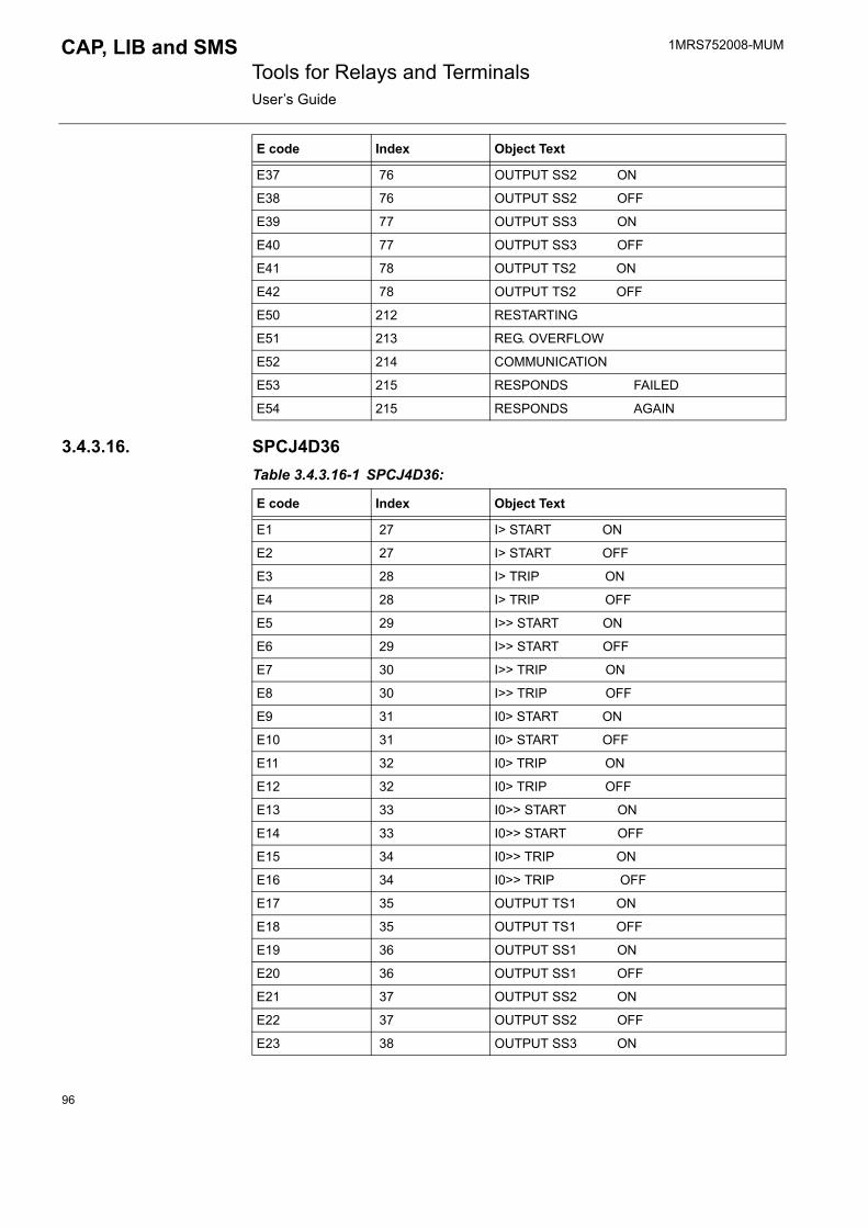
1MRS752008-MUM Tools for Relays and TerminalsUser�s Guide
CAP, LIB and SMS
3.4.3.16. SPCJ4D36Table 3.4.3.16-1 SPCJ4D36:
E37 76 OUTPUT SS2 ON
E38 76 OUTPUT SS2 OFF
E39 77 OUTPUT SS3 ON
E40 77 OUTPUT SS3 OFF
E41 78 OUTPUT TS2 ON
E42 78 OUTPUT TS2 OFF
E50 212 RESTARTING
E51 213 REG. OVERFLOW
E52 214 COMMUNICATION
E53 215 RESPONDS FAILED
E54 215 RESPONDS AGAIN
E code Index Object Text
E code Index Object Text
E1 27 I> START ON
E2 27 I> START OFF
E3 28 I> TRIP ON
E4 28 I> TRIP OFF
E5 29 I>> START ON
E6 29 I>> START OFF
E7 30 I>> TRIP ON
E8 30 I>> TRIP OFF
E9 31 I0> START ON
E10 31 I0> START OFF
E11 32 I0> TRIP ON
E12 32 I0> TRIP OFF
E13 33 I0>> START ON
E14 33 I0>> START OFF
E15 34 I0>> TRIP ON
E16 34 I0>> TRIP OFF
E17 35 OUTPUT TS1 ON
E18 35 OUTPUT TS1 OFF
E19 36 OUTPUT SS1 ON
E20 36 OUTPUT SS1 OFF
E21 37 OUTPUT SS2 ON
E22 37 OUTPUT SS2 OFF
E23 38 OUTPUT SS3 ON
96
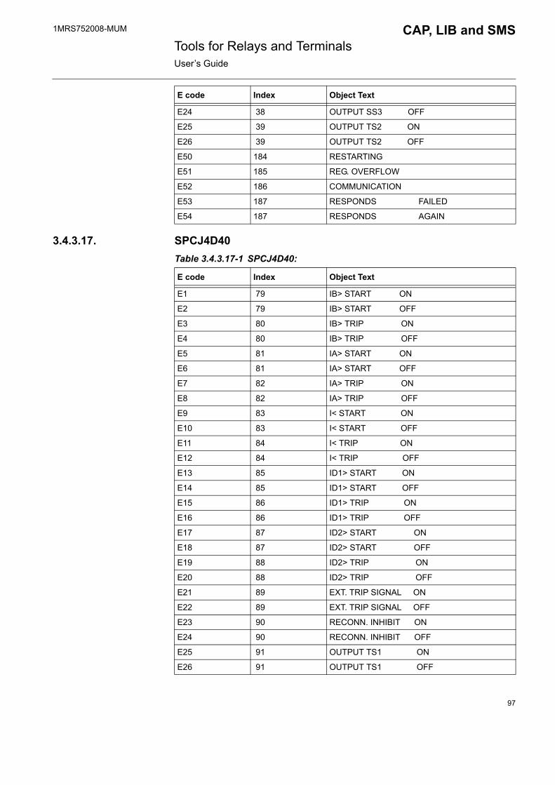
1MRS752008-MUM CAP, LIB and SMS Tools for Relays and TerminalsUser�s Guide
3.4.3.17. SPCJ4D40Table 3.4.3.17-1 SPCJ4D40:
E24 38 OUTPUT SS3 OFF
E25 39 OUTPUT TS2 ON
E26 39 OUTPUT TS2 OFF
E50 184 RESTARTING
E51 185 REG. OVERFLOW
E52 186 COMMUNICATION
E53 187 RESPONDS FAILED
E54 187 RESPONDS AGAIN
E code Index Object Text
E code Index Object Text
E1 79 IB> START ON
E2 79 IB> START OFF
E3 80 IB> TRIP ON
E4 80 IB> TRIP OFF
E5 81 IA> START ON
E6 81 IA> START OFF
E7 82 IA> TRIP ON
E8 82 IA> TRIP OFF
E9 83 I< START ON
E10 83 I< START OFF
E11 84 I< TRIP ON
E12 84 I< TRIP OFF
E13 85 ID1> START ON
E14 85 ID1> START OFF
E15 86 ID1> TRIP ON
E16 86 ID1> TRIP OFF
E17 87 ID2> START ON
E18 87 ID2> START OFF
E19 88 ID2> TRIP ON
E20 88 ID2> TRIP OFF
E21 89 EXT. TRIP SIGNAL ON
E22 89 EXT. TRIP SIGNAL OFF
E23 90 RECONN. INHIBIT ON
E24 90 RECONN. INHIBIT OFF
E25 91 OUTPUT TS1 ON
E26 91 OUTPUT TS1 OFF
97

1MRS752008-MUM Tools for Relays and TerminalsUser�s Guide
CAP, LIB and SMS
3.4.3.18. SPCJ4D44Table 3.4.3.18-1 SPCJ4D44:
E27 92 OUTPUT SS1 ON
E28 92 OUTPUT SS1 OFF
E29 93 OUTPUT SS2 ON
E30 93 OUTPUT SS2 OFF
E31 94 OUTPUT SS3 ON
E32 94 OUTPUT SS3 OFF
E33 95 OUTPUT TS2 ON
E34 95 OUTPUT TS2 OFF
E50 216 RESTARTING
E51 217 REG. OVERFLOW
E52 218 COMMUNICATION
E53 219 RESPONDS FAILED
E54 219 RESPONDS AGAIN
E code Index Object Text
E code Index Object Text
E1 96 I> START ON
E2 96 I> START OFF
E3 97 I> TRIP ON
E4 97 I> TRIP OFF
E5 98 I>> START ON
E6 98 I>> START OFF
E7 99 I>> TRIP ON
E8 99 I>> TRIP OFF
E9 100 I01> START ON
E10 100 I01> START OFF
E11 101 I01> TRIP ON
E12 101 I01> TRIP OFF
E13 102 U0> START ON
E14 102 U0> START OFF
E15 103 I02>> TRIP ON
E16 103 I02>> TRIP OFF
E17 104 OUTPUT TS1 ON
E18 104 OUTPUT TS1 OFF
E19 105 OUTPUT SS1 ON
E20 105 OUTPUT SS1 OFF
E21 106 OUTPUT SS2 ON
98

1MRS752008-MUM CAP, LIB and SMS Tools for Relays and TerminalsUser�s Guide
3.4.3.19. SACO16A3Table 3.4.3.19-1 SACO16A3:
E22 106 OUTPUT SS2 OFF
E23 107 OUTPUT SS3 ON
E24 107 OUTPUT SS3 OFF
E25 108 OUTPUT TS2 ON
E26 108 OUTPUT TS2 OFF
E50 220 RESTARTING
E51 221 REG. OVERFLOW
E52 222 COMMUNICATION
E53 223 RESPONDS FAILED
E54 223 RESPONDS AGAIN
E code Index Object Text
E code Index Object Text
E1 150 HI SET-POINT VAL. ACTIVE
E2 150 HI SET-POINT VAL. RESET
E3 151 BLK. SET-POINT VAL. ACTIVE
E4 151 BLK. SET-POINT VAL. RESET
E7 153 PARAM. MEM. INIT. START
E8 153 PARAM. MEM. INIT. EXEC
E10 154 INT. UNIT FAULT
E13 156 EVENT REG. OVERFLOW
E22 157 EARTH-FAULT ACTIVE
E23 157 EARTH-FAULT RESET
E50 180 RESTARTING
E51 181 REG. OVERFLOW
E52 182 COMMUNICATION
E53 183 RESPONDS FAILED
E54 183 RESPONDS AGAIN
Channel 1
E1 11 CH1 HI SET-P. VAL. START
E2 11 CH1 HI SET-P. VAL. RESET
E3 12 CH1 HI TRIP SET-P V START
E4 12 CH1 HI TRIP SET-P V RESET
E5 13 CH1 LO SET-P. VAL. START
E6 13 CH1 LO SET-P. VAL. RESET
E7 14 CH1 LO TRIP SET-P V START
E8 14 CH1 LO TRIP SET-P V RESET
99

1MRS752008-MUM Tools for Relays and TerminalsUser�s Guide
CAP, LIB and SMS
E15 15 CH1 MEAS. DEVI. REG UPWARDS
E16 15 CH1 MEAS. DEVI. REG DOWNWARDS
E20 16 CH1 MEAS. RANGE UPW ACTIVE
E21 17 CH1 MEAS. RANGE DWNW ACTIVE
E23 18 CH1 TRIP. IND. OSC. ALARM
E24 16 CH1 MEAS. RANGE UPW RESET
E25 17 CH1 MEAS. RANGE DWNW RESET
Channel 2
E1 19 CH2 HI SET-P. VAL. START
E2 19 CH2 HI SET-P. VAL. RESET
E3 20 CH2 HI TRIP SET-P V START
E4 20 CH2 HI TRIP SET-P V RESET
E5 21 CH2 LO SET-P. VAL. START
E6 21 CH2 LO SET-P. VAL. RESET
E7 22 CH2 LO TRIP SET-P V START
E8 22 CH2 LO TRIP SET-P V RESET
E15 23 CH2 MEAS. DEVI. REG UPWARDS
E16 23 CH2 MEAS. DEVI. REG DOWNWARDS
E20 24 CH2 MEAS. RANGE UPW ACTIVE
E21 25 CH2 MEAS. RANGE DWNW ACTIVE
E23 26 CH2 TRIP. IND. OSC. ALARM
E24 24 CH2 MEAS. RANGE UPW RESET
E25 25 CH2 MEAS. RANGE DWNW RESET
Channel 3
E1 27 CH3 HI SET-P. VAL. START
E2 27 CH3 HI SET-P. VAL. RESET
E3 28 CH3 HI TRIP SET-P V START
E4 28 CH3 HI TRIP SET-P V RESET
E5 29 CH3 LO SET-P. VAL. START
E6 29 CH3 LO SET-P. VAL. RESET
E7 30 CH3 LO TRIP SET-P V START
E8 30 CH3 LO TRIP SET-P V RESET
E15 31 CH3 MEAS. DEVI. REG UPWARDS
E16 31 CH3 MEAS. DEVI. REG DOWNWARDS
E20 32 CH3 MEAS. RANGE UPW ACTIVE
E21 33 CH3 MEAS. RANGE DWNW ACTIVE
E23 34 CH3 TRIP. IND. OSC. ALARM
E24 32 CH3 MEAS. RANGE UPW RESET
E25 33 CH3 MEAS. RANGE DWNW RESET
E code Index Object Text
100
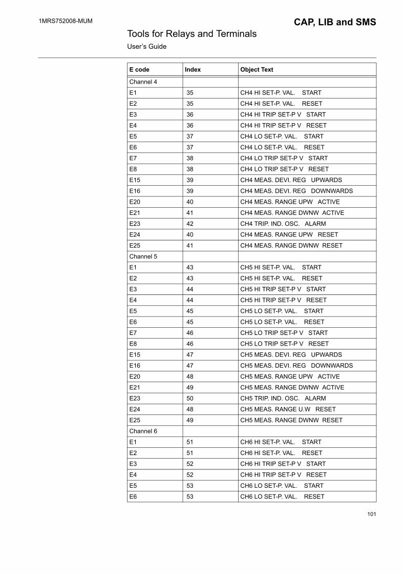
1MRS752008-MUM CAP, LIB and SMS Tools for Relays and TerminalsUser�s Guide
Channel 4
E1 35 CH4 HI SET-P. VAL. START
E2 35 CH4 HI SET-P. VAL. RESET
E3 36 CH4 HI TRIP SET-P V START
E4 36 CH4 HI TRIP SET-P V RESET
E5 37 CH4 LO SET-P. VAL. START
E6 37 CH4 LO SET-P. VAL. RESET
E7 38 CH4 LO TRIP SET-P V START
E8 38 CH4 LO TRIP SET-P V RESET
E15 39 CH4 MEAS. DEVI. REG UPWARDS
E16 39 CH4 MEAS. DEVI. REG DOWNWARDS
E20 40 CH4 MEAS. RANGE UPW ACTIVE
E21 41 CH4 MEAS. RANGE DWNW ACTIVE
E23 42 CH4 TRIP. IND. OSC. ALARM
E24 40 CH4 MEAS. RANGE UPW RESET
E25 41 CH4 MEAS. RANGE DWNW RESET
Channel 5
E1 43 CH5 HI SET-P. VAL. START
E2 43 CH5 HI SET-P. VAL. RESET
E3 44 CH5 HI TRIP SET-P V START
E4 44 CH5 HI TRIP SET-P V RESET
E5 45 CH5 LO SET-P. VAL. START
E6 45 CH5 LO SET-P. VAL. RESET
E7 46 CH5 LO TRIP SET-P V START
E8 46 CH5 LO TRIP SET-P V RESET
E15 47 CH5 MEAS. DEVI. REG UPWARDS
E16 47 CH5 MEAS. DEVI. REG DOWNWARDS
E20 48 CH5 MEAS. RANGE UPW ACTIVE
E21 49 CH5 MEAS. RANGE DWNW ACTIVE
E23 50 CH5 TRIP. IND. OSC. ALARM
E24 48 CH5 MEAS. RANGE U.W RESET
E25 49 CH5 MEAS. RANGE DWNW RESET
Channel 6
E1 51 CH6 HI SET-P. VAL. START
E2 51 CH6 HI SET-P. VAL. RESET
E3 52 CH6 HI TRIP SET-P V START
E4 52 CH6 HI TRIP SET-P V RESET
E5 53 CH6 LO SET-P. VAL. START
E6 53 CH6 LO SET-P. VAL. RESET
E code Index Object Text
101

1MRS752008-MUM Tools for Relays and TerminalsUser�s Guide
CAP, LIB and SMS
E7 54 CH6 LO TRIP SET-P V START
E8 54 CH6 LO TRIP SET-P V RESET
E15 55 CH6 MEAS. DEVI. REG UPWARDS
E16 55 CH6 MEAS. DEVI. REG DOWNWARDS
E20 56 CH6 MEAS. RANGE UPW ACTIVE
E21 57 CH6 MEAS. RANGE DWNW ACTIVE
E23 58 CH6 TRIP. IND. OSC. ALARM
E24 56 CH6 MEAS. RANGE UPW RESET
E25 57 CH6 MEAS. RANGE DWNW RESET
Channel 7
E1 59 CH7 HI SET-P. VAL. START
E2 59 CH7 HI SET-P. VAL. RESET
E3 60 CH7 HI TRIP SET-P V START
E4 60 CH7 HI TRIP SET-P V RESET
E5 61 CH7 LO SET-P. VAL. START
E6 61 CH7 LO SET-P. VAL. RESET
E7 62 CH7 LO TRIP SET-P V START
E8 62 CH7 LO TRIP SET-P V RESET
E15 63 CH7 MEAS. DEVI. REG UPWARDS
E16 63 CH7 MEAS. DEVI. REG DOWNWARDS
E20 64 CH7 MEAS. RANGE UPW ACTIVE
E21 65 CH7 MEAS. RANGE DWNW ACTIVE
E23 66 CH7 TRIP. IND. OSC. ALARM
E24 64 CH7 MEAS. RANGE UPW RESET
E25 65 CH7 MEAS. RANGE DWNW RESET
Channel 8
E1 67 CH8 HI SET-P. VAL. START
E2 67 CH8 HI SET-P. VAL. RESET
E3 68 CH8 HI TRIP SET-P V START
E4 68 CH8 HI TRIP SET-P V RESET
E5 69 CH8 LO SET-P. VAL. START
E6 69 CH8 LO SET-P. VAL. RESET
E7 70 CH8 LO TRIP SET-P V START
E8 70 CH8 LO TRIP SET-P V RESET
E15 71 CH8 MEAS. DEVI. REG UPWARDS
E16 71 CH8 MEAS. DEVI. REG DOWNWARDS
E20 72 CH8 MEAS. RANGE UPW ACTIVE
E21 73 CH8 MEAS. RANGE DWNW ACTIVE
E23 74 CH8 TRIP. IND. OSC. ALARM
E code Index Object Text
102

1MRS752008-MUM CAP, LIB and SMS Tools for Relays and TerminalsUser�s Guide
E24 72 CH8 MEAS. RANGE UPW RESET
E25 73 CH8 MEAS. RANGE DWNW RESET
Channel 9
E1 75 CH9 HI SET-P. VAL. START
E2 75 CH9 HI SET-P. VAL. RESET
E3 76 CH9 HI TRIP SET-P V START
E4 76 CH9 HI TRIP SET-P V RESET
E5 77 CH9 LO SET-P. VAL. START
E6 77 CH9 LO SET-P. VAL. RESET
E7 78 CH9 LO TRIP SET-P V START
E8 78 CH9 LO TRIP SET-P V RESET
E15 79 CH9 MEAS. DEVI. REG UPWARDS
E16 79 CH9 MEAS. DEVI. REG DOWNWARDS
E20 80 CH9 MEAS. RANGE UPW ACTIVE
E21 81 CH9 MEAS. RANGE DWNW ACTIVE
E23 82 CH9 TRIP. IND. OSC. ALARM
E24 80 CH9 MEAS. RANGE UPW RESET
E25 81 CH9 MEAS. RANGE DWNW RESET
Channel 10
E1 83 CH10 HI SET-P. VAL. START
E2 83 CH10 HI SET-P. VAL. RESET
E3 84 CH10 HI TRIP SET-P V START
E4 84 CH10 HI TRIP SET-P V RESET
E5 85 CH10 LO SET-P. VAL. START
E6 85 CH10 LO SET-P. VAL. RESET
E7 86 CH10 LO TRIP SET-P V START
E8 86 CH10 LO TRIP SET-P V RESET
E15 87 CH10 MEAS. DEVI. REG UPWARDS
E16 87 CH10 MEAS. DEVI. REG DOWNWARDS
E20 88 CH10 MEAS. RANGE UPW ACTIVE
E21 89 CH10 MEAS. RANGE DWNW ACTIVE
E23 90 CH10 TRIP. IND. OSC. ALARM
E24 88 CH10 MEAS. RANGE UPW RESET
E25 89 CH10 MEAS. RANGE DWNW RESET
Channel 11
E1 91 CH11 HI SET-P. VAL. START
E2 91 CH11 HI SET-P. VAL. RESET
E3 92 CH11 HI TRIP SET-P V START
E4 92 CH11 HI TRIP SET-P V RESET
E code Index Object Text
103
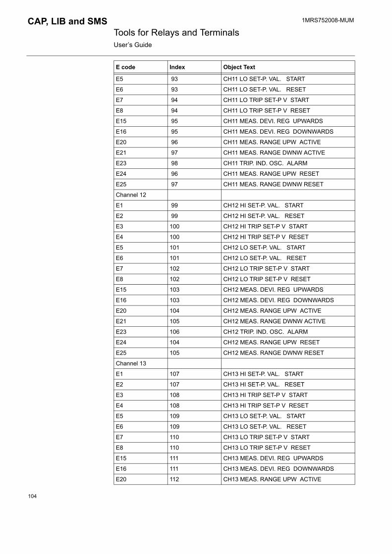
1MRS752008-MUM Tools for Relays and TerminalsUser�s Guide
CAP, LIB and SMS
E5 93 CH11 LO SET-P. VAL. START
E6 93 CH11 LO SET-P. VAL. RESET
E7 94 CH11 LO TRIP SET-P V START
E8 94 CH11 LO TRIP SET-P V RESET
E15 95 CH11 MEAS. DEVI. REG UPWARDS
E16 95 CH11 MEAS. DEVI. REG DOWNWARDS
E20 96 CH11 MEAS. RANGE UPW ACTIVE
E21 97 CH11 MEAS. RANGE DWNW ACTIVE
E23 98 CH11 TRIP. IND. OSC. ALARM
E24 96 CH11 MEAS. RANGE UPW RESET
E25 97 CH11 MEAS. RANGE DWNW RESET
Channel 12
E1 99 CH12 HI SET-P. VAL. START
E2 99 CH12 HI SET-P. VAL. RESET
E3 100 CH12 HI TRIP SET-P V START
E4 100 CH12 HI TRIP SET-P V RESET
E5 101 CH12 LO SET-P. VAL. START
E6 101 CH12 LO SET-P. VAL. RESET
E7 102 CH12 LO TRIP SET-P V START
E8 102 CH12 LO TRIP SET-P V RESET
E15 103 CH12 MEAS. DEVI. REG UPWARDS
E16 103 CH12 MEAS. DEVI. REG DOWNWARDS
E20 104 CH12 MEAS. RANGE UPW ACTIVE
E21 105 CH12 MEAS. RANGE DWNW ACTIVE
E23 106 CH12 TRIP. IND. OSC. ALARM
E24 104 CH12 MEAS. RANGE UPW RESET
E25 105 CH12 MEAS. RANGE DWNW RESET
Channel 13
E1 107 CH13 HI SET-P. VAL. START
E2 107 CH13 HI SET-P. VAL. RESET
E3 108 CH13 HI TRIP SET-P V START
E4 108 CH13 HI TRIP SET-P V RESET
E5 109 CH13 LO SET-P. VAL. START
E6 109 CH13 LO SET-P. VAL. RESET
E7 110 CH13 LO TRIP SET-P V START
E8 110 CH13 LO TRIP SET-P V RESET
E15 111 CH13 MEAS. DEVI. REG UPWARDS
E16 111 CH13 MEAS. DEVI. REG DOWNWARDS
E20 112 CH13 MEAS. RANGE UPW ACTIVE
E code Index Object Text
104

1MRS752008-MUM CAP, LIB and SMS Tools for Relays and TerminalsUser�s Guide
E21 113 CH13 MEAS. RANGE DWNW ACTIVE
E23 114 CH13 TRIP. IND. OSC. ALARM
E24 112 CH13 MEAS. RANGE UPW RESET
E25 113 CH13 MEAS. RANGE DWNW RESET
Channel 14
E1 115 CH14 HI SET-P. VAL. START
E2 115 CH14 HI SET-P. VAL. RESET
E3 116 CH14 HI TRIP SET-P V START
E4 116 CH14 HI TRIP SET-P V RESET
E5 117 CH14 LO SET-P. VAL. START
E6 117 CH14 LO SET-P. VAL. RESET
E7 118 CH14 LO TRIP SET-P V START
E8 118 CH14 LO TRIP SET-P V RESET
E15 119 CH14 MEAS. DEVI. REG UPWARDS
E16 119 CH14 MEAS. DEVI. REG DOWNWARDS
E20 120 CH14 MEAS. RANGE UPW ACTIVE
E21 121 CH14 MEAS. RANGE DWNW ACTIVE
E23 122 CH14 TRIP. IND. OSC. ALARM
E24 120 CH14 MEAS. RANGE UPW RESET
E25 121 CH14 MEAS. RANGE DWNW RESET
Channel 15
E1 123 CH15 HI SET-P. VAL. START
E2 123 CH15 HI SET-P. VAL. RESET
E3 124 CH15 HI TRIP SET-P V START
E4 124 CH15 HI TRIP SET-P V RESET
E5 125 CH15 LO SET-P. VAL. START
E6 125 CH15 LO SET-P. VAL. RESET
E7 126 CH15 LO TRIP SET-P V START
E8 126 CH15 LO TRIP SET-P V RESET
E15 127 CH15 MEAS. DEVI. REG UPWARDS
E16 127 CH15 MEAS. DEVI. REG DOWNWARDS
E20 128 CH15 MEAS. RANGE UPW ACTIVE
E21 129 CH15 MEAS. RANGE DWNW ACTIVE
E23 130 CH15 TRIP. IND. OSC. ALARM
E24 128 CH15 MEAS. RANGE UPW RESET
E25 129 CH15 MEAS. RANGE DWNW RESET
Channel 16
E1 131 CH16 HI SET-P. VAL. START
E2 131 CH16 HI SET-P. VAL. RESET
E code Index Object Text
105

1MRS752008-MUM Tools for Relays and TerminalsUser�s Guide
CAP, LIB and SMS
3.4.3.20. SACO16D2Table 3.4.3.20-1 SACO16D2:
E3 132 CH16 HI TRIP SET-P V START
E4 132 CH16 HI TRIP SET-P V RESET
E5 133 CH16 LO SET-P. VAL. START
E6 133 CH16 LO SET-P. VAL. RESET
E7 134 CH16 LO TRIP SET-P V START
E8 134 CH16 LO TRIP SET-P V RESET
E15 135 CH16 MEAS. DEVI. REG UPWARDS
E16 135 CH16 MEAS. DEVI. REG DOWNWARDS
E20 136 CH16 MEAS. RANGE UPW ACTIVE
E21 137 CH16 MEAS. RANGE DWNW ACTIVE
E23 138 CH16 TRIP. IND. OSC. ALARM
E24 136 CH16 MEAS. RANGE UPW RESET
E25 137 CH16 MEAS. RANGE DWNW RESET
E code Index Object Text
E code Index Object Text
E10 125 INT. UNIT FAULT
E13 126 EVENT REG. OVERFLOW
E50 220 RESTARTING
E51 221 REG. OVERFLOW
E52 222 COMMUNICATION
E53 223 RESPONDS FAILED
E54 223 RESPONDS AGAIN
Channel 1
E1 91 CH1 ALARM
E2 91 CH1 RESET
E3 91 CH1 ALARM
E4 91 CH1 RESET
Channel 2
E1 92 CH2 ALARM
E2 92 CH2 RESET
E3 92 CH2 ALARM
E4 92 CH2 RESET
Channel 3
E1 93 CH3 ALARM
E2 93 CH3 RESET
106

1MRS752008-MUM CAP, LIB and SMS Tools for Relays and TerminalsUser�s Guide
E3 93 CH3 ALARM
E4 93 CH3 RESET
Channel 4
E1 94 CH4 ALARM
E2 94 CH4 RESET
E3 94 CH4 ALARM
E4 94 CH4 RESET
Channel 5
E1 95 CH5 ALARM
E2 95 CH5 RESET
E3 95 CH5 ALARM
E4 95 CH5 RESET
Channel 6
E1 96 CH6 ALARM
E2 96 CH6 RESET
E3 96 CH6 ALARM
E4 96 CH6 RESET
Channel 7
E1 97 CH7 ALARM
E2 97 CH7 RESET
E3 97 CH7 ALARM
E4 97 CH7 RESET
Channel 8
E1 98 CH8 ALARM
E2 98 CH8 RESET
E3 98 CH8 ALARM
E4 98 CH8 RESET
Channel 9
E1 99 CH9 ALARM
E2 99 CH9 RESET
E3 99 CH9 ALARM
E4 99 CH9 RESET
Channel 10
E1 100 CH10 ALARM
E2 100 CH10 RESET
E3 100 CH10 ALARM
E4 100 CH10 RESET
Channel 11
E1 101 CH11 ALARM
E code Index Object Text
107

1MRS752008-MUM Tools for Relays and TerminalsUser�s Guide
CAP, LIB and SMS
3.4.3.21. SACO16D1B
E2 101 CH11 RESET
E3 101 CH11 ALARM
E4 101 CH11 RESET
Channel 12
E1 102 CH12 ALARM
E2 102 CH12 RESET
E3 102 CH12 ALARM
E4 102 CH12 RESET
Channel 13
E1 103 CH13 ALARM
E2 103 CH13 RESET
E3 103 CH13 ALARM
E4 103 CH13 RESET
Channel 14
E1 104 CH14 ALARM
E2 104 CH14 RESET
E3 104 CH14 ALARM
E4 104 CH14 RESET
Channel 15
E1 105 CH15 ALARM
E2 105 CH15 RESET
E3 105 CH15 ALARM
E4 105 CH15 RESET
Channel 16
E1 106 CH16 ALARM
E2 106 CH16 RESET
E3 106 CH16 ALARM
E4 106 CH16 RESET
E code Index Object Text
E code Index Object Text
E10 79 INT. UNIT FAULT
E13 80 EVENT REG. OVERFLOW
E50 194 RESTARTING
E51 195 REG. OVERFLOW
E52 196 COMMUNICATION
E53 197 RESPONDS FAILED
E54 197 RESPONDS AGAIN
108
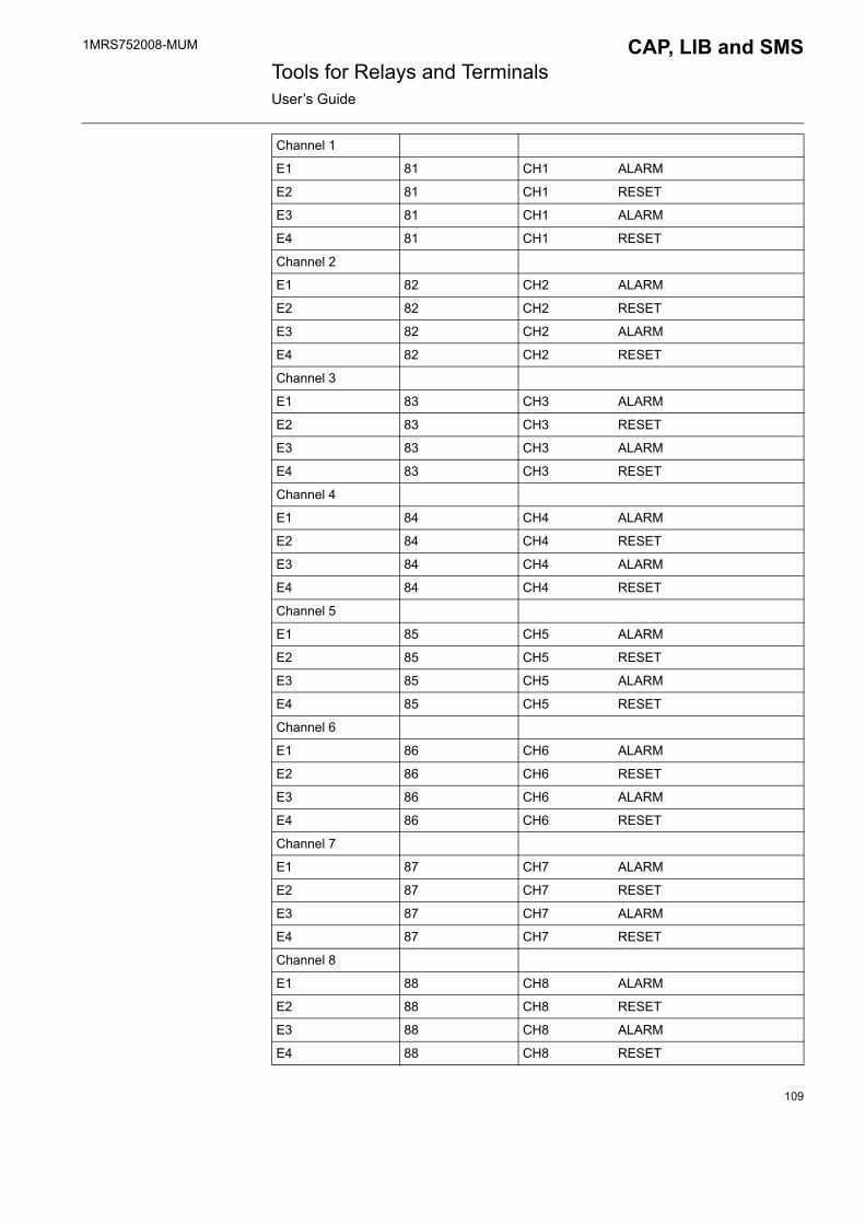
1MRS752008-MUM CAP, LIB and SMS Tools for Relays and TerminalsUser�s Guide
Channel 1
E1 81 CH1 ALARM
E2 81 CH1 RESET
E3 81 CH1 ALARM
E4 81 CH1 RESET
Channel 2
E1 82 CH2 ALARM
E2 82 CH2 RESET
E3 82 CH2 ALARM
E4 82 CH2 RESET
Channel 3
E1 83 CH3 ALARM
E2 83 CH3 RESET
E3 83 CH3 ALARM
E4 83 CH3 RESET
Channel 4
E1 84 CH4 ALARM
E2 84 CH4 RESET
E3 84 CH4 ALARM
E4 84 CH4 RESET
Channel 5
E1 85 CH5 ALARM
E2 85 CH5 RESET
E3 85 CH5 ALARM
E4 85 CH5 RESET
Channel 6
E1 86 CH6 ALARM
E2 86 CH6 RESET
E3 86 CH6 ALARM
E4 86 CH6 RESET
Channel 7
E1 87 CH7 ALARM
E2 87 CH7 RESET
E3 87 CH7 ALARM
E4 87 CH7 RESET
Channel 8
E1 88 CH8 ALARM
E2 88 CH8 RESET
E3 88 CH8 ALARM
E4 88 CH8 RESET
109

1MRS752008-MUM Tools for Relays and TerminalsUser�s Guide
CAP, LIB and SMS
Channel 9
E1 89 CH9 ALARM
E2 89 CH9 RESET
E3 89 CH9 ALARM
E4 89 CH9 RESET
Channel 10
E1 90 CH10 ALARM
E2 90 CH10 RESET
E3 90 CH10 ALARM
E4 90 CH10 RESET
Channel 11
E1 91 CH11 ALARM
E2 91 CH11 RESET
E3 91 CH11 ALARM
E4 91 CH11 RESET
Channel 12
E1 92 CH12 ALARM
E2 92 CH12 RESET
E3 92 CH12 ALARM
E4 92 CH12 RESET
Channel 13
E1 93 CH13 ALARM
E2 93 CH13 RESET
E3 93 CH13 ALARM
E4 93 CH13 RESET
Channel 14
E1 94 CH14 ALARM
E2 94 CH14 RESET
E3 94 CH14 ALARM
E4 94 CH14 RESET
Channel 15
E1 95 CH15 ALARM
E2 95 CH15 RESET
E3 95 CH15 ALARM
E4 95 CH15 RESET
Channel 16
E1 96 CH16 ALARM
E2 96 CH16 RESET
E3 96 CH16 ALARM
E4 96 CH16 RESET
110

1MRS752008-MUM CAP, LIB and SMS Tools for Relays and TerminalsUser�s Guide
3.4.3.22. SACO16D2BTable 3.4.3.22-1 SACO16D2B:
E code Index Object Text
E10 100 INT. UNIT FAULT
E13 101 EVENT REG. OVERFLOW
E50 198 RESTARTING
E51 199 REG. OVERFLOW
E52 200 COMMUNICATION
E53 201 RESPONDS FAILED
E54 201 RESPONDS AGAIN
Channel 1
E1 102 CH1 ALARM
E2 102 CH1 RESET
E3 102 CH1 ALARM
E4 102 CH1 RESET
Channel 2
E1 103 CH2 ALARM
E2 103 CH2 RESET
E3 103 CH2 ALARM
E4 103 CH2 RESET
Channel 3
E1 104 CH3 ALARM
E2 104 CH3 RESET
E3 104 CH3 ALARM
E4 104 CH3 RESET
Channel 4
E1 105 CH4 ALARM
E2 105 CH4 RESET
E3 105 CH4 ALARM
E4 105 CH4 RESET
Channel 5
E1 106 CH5 ALARM
E2 106 CH5 RESET
E3 106 CH5 ALARM
E4 106 CH5 RESET
Channel 6
E1 107 CH6 ALARM
E2 107 CH6 RESET
E3 107 CH6 ALARM
111

1MRS752008-MUM Tools for Relays and TerminalsUser�s Guide
CAP, LIB and SMS
E4 107 CH6 RESET
Channel 7
E1 108 CH7 ALARM
E2 108 CH7 RESET
E3 108 CH7 ALARM
E4 108 CH7 RESET
Channel 8
E1 109 CH8 ALARM
E2 109 CH8 RESET
E3 109 CH8 ALARM
E4 109 CH8 RESET
Channel 9
E1 110 CH9 ALARM
E2 110 CH9 RESET
E3 110 CH9 ALARM
E4 110 CH9 RESET
Channel 10
E1 111 CH10 ALARM
E2 111 CH10 RESET
E3 111 CH10 ALARM
E4 111 CH10 RESET
Channel 11
E1 112 CH11 ALARM
E2 112 CH11 RESET
E3 112 CH11 ALARM
E4 112 CH11 RESET
Channel 12
E1 113 CH12 ALARM
E2 113 CH12 RESET
E3 113 CH12 ALARM
E4 113 CH12 RESET
Channel 13
E1 114 CH13 ALARM
E2 114 CH13 RESET
E3 114 CH13 ALARM
E4 114 CH13 RESET
Channel 14
E1 115 CH14 ALARM
E2 115 CH14 RESET
E code Index Object Text
112

1MRS752008-MUM CAP, LIB and SMS Tools for Relays and TerminalsUser�s Guide
3.4.3.23. SPCP3C2Table 3.4.3.23-1 SPCP3C2:
3.4.3.24. SPCS2D37Table 3.4.3.24-1 SPCS2D37:
E3 115 CH14 ALARM
E4 115 CH14 RESET
Channel 15
E1 116 CH15 ALARM
E2 116 CH15 RESET
E3 116 CH15 ALARM
E4 116 CH15 RESET
Channel 16
E1 117 CH16 ALARM
E2 117 CH16 RESET
E3 117 CH16 ALARM
E4 117 CH16 RESET
E code Index Object Text
E code Index Object Text
E1 61 U>, U>> START ON
E2 61 U>, U>> START OFF
E3 62 U>, U>> TRIP ON
E4 62 U>, U>> TRIP OFF
E5 63 REV. POWER START ON
E6 63 REV. POWER START OFF
E7 64 REV. POWER TRIP ON
E8 64 REV. POWER TRIP OFF
E50 200 RESTARTING
E51 201 REG. OVERFLOW
E52 202 COMMUNICATION
E53 203 RESPONDS FAILED
E54 203 RESPONDS AGAIN
E code Index Object Text
E1 11 I01> START ON
E2 11 I01> START OFF
E3 12 I01> FIRST TRIP ON
E4 12 I01> FIRST TRIP OFF
113

1MRS752008-MUM Tools for Relays and TerminalsUser�s Guide
CAP, LIB and SMS
3.4.3.25. SPCS3C4Table 3.4.3.25-1 SPCS3C4:
E7 14 I01> SECOND TRIP ON
E8 14 I01> SECOND TRIP OFF
E9 15 I02> START ON
E10 15 I02> START OFF
E11 16 I02> TRIP ON
E12 16 I02> TRIP OFF
E13 17 I03> START ON
E14 17 I03> START OFF
E15 18 I03> TRIP ON
E16 18 I03> TRIP OFF
E17 19 OUTPUT SS1 ON
E18 19 OUTPUT SS1 OFF
E19 20 OUTPUT TS1 ON
E20 20 OUTPUT TS1 OFF
E21 21 OUTPUT SS2 ON
E22 21 OUTPUT SS2 OFF
E23 22 OUTPUT TS2 ON
E24 22 OUTPUT TS2 OFF
E25 23 OUTPUT SS3 ON
E26 23 OUTPUT SS3 OFF
E27 24 OUTPUT TS3 ON
E28 24 OUTPUT TS3 OFF
E29 25 OUTPUT SS4 ON
E30 25 OUTPUT SS4 OFF
E31 26 OUTPUT TS4 ON
E32 26 OUTPUT TS4 OFF
E50 180 RESTARTING
E51 181 REG. OVERFLOW
E52 182 COMMUNICATION
E53 183 RESPONDS FAILED
E54 183 RESPONDS AGAIN
E code Index Object Text
E code Index Object Text
E1 28 IF> START ON
E2 28 IF> START OFF
E3 29 IF> TRIP ON
114

1MRS752008-MUM CAP, LIB and SMS Tools for Relays and TerminalsUser�s Guide
3.4.3.26. SPCS4D11Table 3.4.3.26-1 SPCS4D11:
E4 29 IF> TRIP OFF
E5 30 IF>> START ON
E6 30 IF>> START OFF
E7 31 IF>> TRIP ON
E8 31 IF>> TRIP OFF
E50 200 RESTARTING
E51 201 REG. OVERFLOW
E52 202 COMMUNICATION
E53 203 RESPONDS FAILED
E54 203 RESPONDS AGAIN
E code Index Object Text
E code Index Object Text
E1 109 I> START FORWARD ON
E2 109 I> START FORWARD OFF
E3 110 I> START REVERSE ON
E4 110 I> START REVERSE OFF
E5 111 I> TRIP ON
E6 111 I> TRIP OFF
E7 112 I>> START ON
E8 112 I>> START OFF
E9 113 I>> TRIP ON
E10 113 I>> TRIP OFF
E11 114 I>>> START ON
E12 114 I>>> START OFF
E13 115 I>>> TRIP ON
E14 115 I>>> TRIP OFF
E15 116
E16 116
E17 117 OUTPUT TS1 ON
E18 117 OUTPUT TS1 OFF
E19 118 OUTPUT SS1 ON
E20 118 OUTPUT SS1 OFF
E21 119 OUTPUT SS2 ON
E22 119 OUTPUT SS2 OFF
E23 120 OUTPUT SS3 ON
E24 120 OUTPUT SS3 OFF
115

1MRS752008-MUM Tools for Relays and TerminalsUser�s Guide
CAP, LIB and SMS
3.4.3.27. SPCS4D12Table 3.4.3.27-1 SPCS4D12:
E25 121 OUTPUT TS2 ON
E26 121 OUTPUT TS2 OFF
E50 224 RESTARTING
E51 225 REG. OVERFLOW
E52 226 COMMUNICATION
E53 227 RESPONDS FAILED
E54 227 RESPONDS AGAIN
E code Index Object Text
E code Index Object Text
E1 122 I> START FORWARD ON
E2 122 I> START FORWARD OFF
E3 123 I> START REVERSE ON
E4 123 I> START REVERSE OFF
E5 124 I> TRIP ON
E6 124 I> TRIP OFF
E7 125 I>> START ON
E8 125 I>> START OFF
E9 126 I>> TRIP ON
E10 126 I>> TRIP OFF
E11 127 I>>> START ON
E12 127 I>>> START OFF
E13 128 I>>> TRIP ON
E14 128 I>>> TRIP OFF
E15 129
E16 129
E17 130 OUTPUT TS1 ON
E18 130 OUTPUT TS1 OFF
E19 131 OUTPUT SS1 ON
E20 131 OUTPUT SS1 OFF
E21 132 OUTPUT SS2 ON
E22 132 OUTPUT SS2 OFF
E23 133 OUTPUT SS3 ON
E24 133 OUTPUT SS3 OFF
E25 134 OUTPUT TS2 ON
E26 134 OUTPUT TS2 OFF
E50 228 RESTARTING
116

1MRS752008-MUM CAP, LIB and SMS Tools for Relays and TerminalsUser�s Guide
3.4.3.28. SPCS4D13Table 3.4.3.28-1 SPCS4D13:
E51 229 REG. OVERFLOW
E52 230 COMMUNICATION
E53 231 RESPONDS FAILED
E54 231 RESPONDS AGAIN
E code Index Object Text
E code Index Object Text
E1 135 I> START FORWARD ON
E2 135 I> START FORWARD OFF
E3 136 I> START REVERSE ON
E4 136 I> START REVERSE OFF
E5 137 I> TRIP ON
E6 137 I> TRIP OFF
E7 138 I>> START ON
E8 138 I>> START OFF
E9 139 I>> TRIP ON
E10 139 I>> TRIP OFF
E11 140 I>>> START ON
E12 140 I>>> START OFF
E13 141 I>>> TRIP ON
E14 141 I>>> TRIP OFF
E15 142
E16 142
E17 143 OUTPUT TS1 ON
E18 143 OUTPUT TS1 OFF
E19 144 OUTPUT SS1 ON
E20 144 OUTPUT SS1 OFF
E21 145 OUTPUT SS2 ON
E22 145 OUTPUT SS2 OFF
E23 146 OUTPUT SS3 ON
E24 146 OUTPUT SS3 OFF
E25 147 OUTPUT TS2 ON
E26 147 OUTPUT TS2 OFF
E50 232 RESTARTING
E51 233 REG. OVERFLOW
117
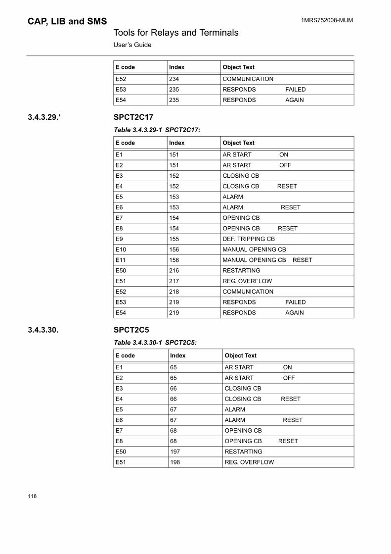
1MRS752008-MUM Tools for Relays and TerminalsUser�s Guide
CAP, LIB and SMS
3.4.3.29.� SPCT2C17Table 3.4.3.29-1 SPCT2C17:
3.4.3.30. SPCT2C5Table 3.4.3.30-1 SPCT2C5:
E52 234 COMMUNICATION
E53 235 RESPONDS FAILED
E54 235 RESPONDS AGAIN
E code Index Object Text
E code Index Object Text
E1 151 AR START ON
E2 151 AR START OFF
E3 152 CLOSING CB
E4 152 CLOSING CB RESET
E5 153 ALARM
E6 153 ALARM RESET
E7 154 OPENING CB
E8 154 OPENING CB RESET
E9 155 DEF. TRIPPING CB
E10 156 MANUAL OPENING CB
E11 156 MANUAL OPENING CB RESET
E50 216 RESTARTING
E51 217 REG. OVERFLOW
E52 218 COMMUNICATION
E53 219 RESPONDS FAILED
E54 219 RESPONDS AGAIN
E code Index Object Text
E1 65 AR START ON
E2 65 AR START OFF
E3 66 CLOSING CB
E4 66 CLOSING CB RESET
E5 67 ALARM
E6 67 ALARM RESET
E7 68 OPENING CB
E8 68 OPENING CB RESET
E50 197 RESTARTING
E51 198 REG. OVERFLOW
118

1MRS752008-MUM CAP, LIB and SMS Tools for Relays and TerminalsUser�s Guide
3.4.3.31. SPCT2D38Table 3.4.3.31-1 SPCT2D38:
E52 199 COMMUNICATION
E53 200 RESPONDS FAILED
E54 200 RESPONDS AGAIN
E code Index Object Text
E code Index Object Text
E1 70 HSAR START ON
E2 70 HSAR START OFF
E3 71 HSAR STARTED BY AR1
E4 72 HSAR STARTED BY AR2
E5 73 HSAR STARTED BY AR3
E6 74 SSAR START ON
E7 74 SSAR START OFF
E8 75 SSAR STARTED BY AR1
E9 76 SSAR STARTED BY AR2
E10 77 SSAR STARTED BY AR3
E11 78 DELAYED SSAR STARTED
E12 78 DELAYED SSAR RESET
E13 79 DEL. SSAR ST. BY AR1
E14 80 DEL. SSAR ST. BY AR2
E15 81 DEL. SSAR ST. BY AR3
E16 82 AUTO RECLOSE ON
E17 82 AUTO RECLOSE OFF
E18 83 AR INHIBITED
E19 83 AR RESETTED
E20 84 CB TRIPPING FAILED
E21 85 CB CLOSING ACTIVATED
E22 85 CB CLOSING RESET
E23 86 CB OPEN FAILED
E24 87 ARF ON
E25 87 ARF OFF
E26 88 DEF. CB TRIPPING
E27 89 NON-AR CB CLOSING
E28 90 NON-PROTEC. CB OPEN.
E50 201 RESTARTING
E51 202 REG. OVERFLOW
119

1MRS752008-MUM Tools for Relays and TerminalsUser�s Guide
CAP, LIB and SMS
3.4.3.32. SPCT2D46Table 3.4.3.32-1 SPCT2D46:
E52 203 COMMUNICATION
E53 204 RESPONDS FAILED
E54 204 RESPONDS AGAIN
E code Index Object Text
E code Index Object Text
E1 91 HSAR FORWARD STARTED
E2 91 HSAR FORWARD RESET
E3 92 HSAR STARTED BY AR1
E4 93 HSAR STARTED BY AR2
E5 94 HSAR STARTED BY AR3
E6 95 SSAR START ON
E7 95 SSAR START OFF
E8 96 SSAR STARTED BY AR1
E9 97 SSAR STARTED BY AR2
E10 98 SSAR STARTED BY AR3
E11 99 TD TIME STARTED
E12 99 TD TIME RESET
E13 100 TN TIME STARTED
E14 100 TN TIME RESET
E15 101 DEFINITE CB TRIPPING
E16 102 DEF. CB TRIP. BY AR1
E17 103 DEF. CB TRIP. BY AR2
E18 104 DEF. CB TRIP. BY AR3
E19 105 AUTO RECLOSE ON
E20 105 AUTO RECLOSE OFF
E21 106 CB CLOSING ACTIVATED
E22 106 CB CLOSING RESET
E23 107 CB OPEN FAILED
E24 108 CB CLOSING FAILED
E25 109 AR INTERRUPTED
E26 110 INT. BLOCKING RESET
E27 111 NON-AR CB CLOSING
E28 112 NON-PROTEC. CB OPEN.
E50 205 RESTARTING
E51 206 REG. OVERFLOW
120

1MRS752008-MUM CAP, LIB and SMS Tools for Relays and TerminalsUser�s Guide
3.4.3.33. SPCU1C1Table 3.4.3.33-1 SPCU1C1:
3.4.3.34. SPCU1C6Table 3.4.3.34-1 SPCU1C6:
E52 207 COMMUNICATION
E53 208 RESPONDS FAILED
E54 208 RESPONDS AGAIN
E code Index Object Text
E1 11 U> START ON
E2 11 U> START OFF
E3 12 U> TRIP ON
E4 12 U> TRIP OFF
E5 13 U< START ON
E6 13 U< START OFF
E7 14 U< TRIP ON
E8 14 U< TRIP OFF
E50 180 RESTARTING
E51 181 REG. OVERFLOW
E52 182 COMMUNICATION
E53 183 RESPONDS FAILED
E54 183 RESPONDS AGAIN
E code Index Object Text
E1 15 U0> START ON
E2 15 U0> START OFF
E3 16 U0> TRIP ON
E4 16 U0> TRIP OFF
E5 17 U0>> START ON
E6 17 U0>> START OFF
E7 18 U0>> TRIP ON
E8 18 U0>> TRIP OFF
E50 184 RESTARTING
E51 185 REG. OVERFLOW
E52 186 COMMUNICATION
E53 187 RESPONDS FAILED
E54 187 RESPONDS AGAIN
121
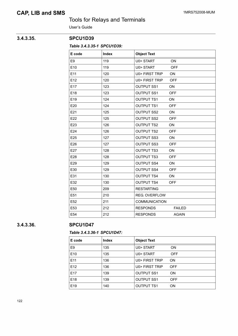
1MRS752008-MUM Tools for Relays and TerminalsUser�s Guide
CAP, LIB and SMS
3.4.3.35. SPCU1D39Table 3.4.3.35-1 SPCU1D39:
3.4.3.36. SPCU1D47Table 3.4.3.36-1 SPCU1D47:
E code Index Object Text
E9 119 U0> START ON
E10 119 U0> START OFF
E11 120 U0> FIRST TRIP ON
E12 120 U0> FIRST TRIP OFF
E17 123 OUTPUT SS1 ON
E18 123 OUTPUT SS1 OFF
E19 124 OUTPUT TS1 ON
E20 124 OUTPUT TS1 OFF
E21 125 OUTPUT SS2 ON
E22 125 OUTPUT SS2 OFF
E23 126 OUTPUT TS2 ON
E24 126 OUTPUT TS2 OFF
E25 127 OUTPUT SS3 ON
E26 127 OUTPUT SS3 OFF
E27 128 OUTPUT TS3 ON
E28 128 OUTPUT TS3 OFF
E29 129 OUTPUT SS4 ON
E30 129 OUTPUT SS4 OFF
E31 130 OUTPUT TS4 ON
E32 130 OUTPUT TS4 OFF
E50 209 RESTARTING
E51 210 REG. OVERFLOW
E52 211 COMMUNICATION
E53 212 RESPONDS FAILED
E54 212 RESPONDS AGAIN
E code Index Object Text
E9 135 U0> START ON
E10 135 U0> START OFF
E11 136 U0> FIRST TRIP ON
E12 136 U0> FIRST TRIP OFF
E17 139 OUTPUT SS1 ON
E18 139 OUTPUT SS1 OFF
E19 140 OUTPUT TS1 ON
122

1MRS752008-MUM CAP, LIB and SMS Tools for Relays and TerminalsUser�s Guide
3.4.3.37. SPCU3C14Table 3.4.3.37-1 SPCU3C14:
E20 140 OUTPUT TS1 OFF
E21 141 OUTPUT SS2 ON
E22 141 OUTPUT SS2 OFF
E23 142 OUTPUT TS2 ON
E24 142 OUTPUT TS2 OFF
E25 143 OUTPUT SS3 ON
E26 143 OUTPUT SS3 OFF
E27 144 OUTPUT TS3 ON
E28 144 OUTPUT TS3 OFF
E29 145 OUTPUT SS4 ON
E30 145 OUTPUT SS4 OFF
E31 146 OUTPUT TS4 ON
E32 146 OUTPUT TS4 OFF
E50 213 RESTARTING
E51 214 REG. OVERFLOW
E52 215 COMMUNICATION
E53 216 RESPONDS FAILED
E54 216 RESPONDS AGAIN
E code Index Object Text
E code Index Object Text
E1 19 U> START ON
E2 19 U> START OFF
E3 20 U> TRIP ON
E4 20 U> TRIP OFF
E5 21 U< START ON
E6 21 U< START OFF
E7 22 U< TRIP ON
E8 22 U< TRIP OFF
E50 188 RESTARTING
E51 189 REG. OVERFLOW
E52 190 COMMUNICATION
E53 191 RESPONDS FAILED
E54 191 RESPONDS AGAIN
123
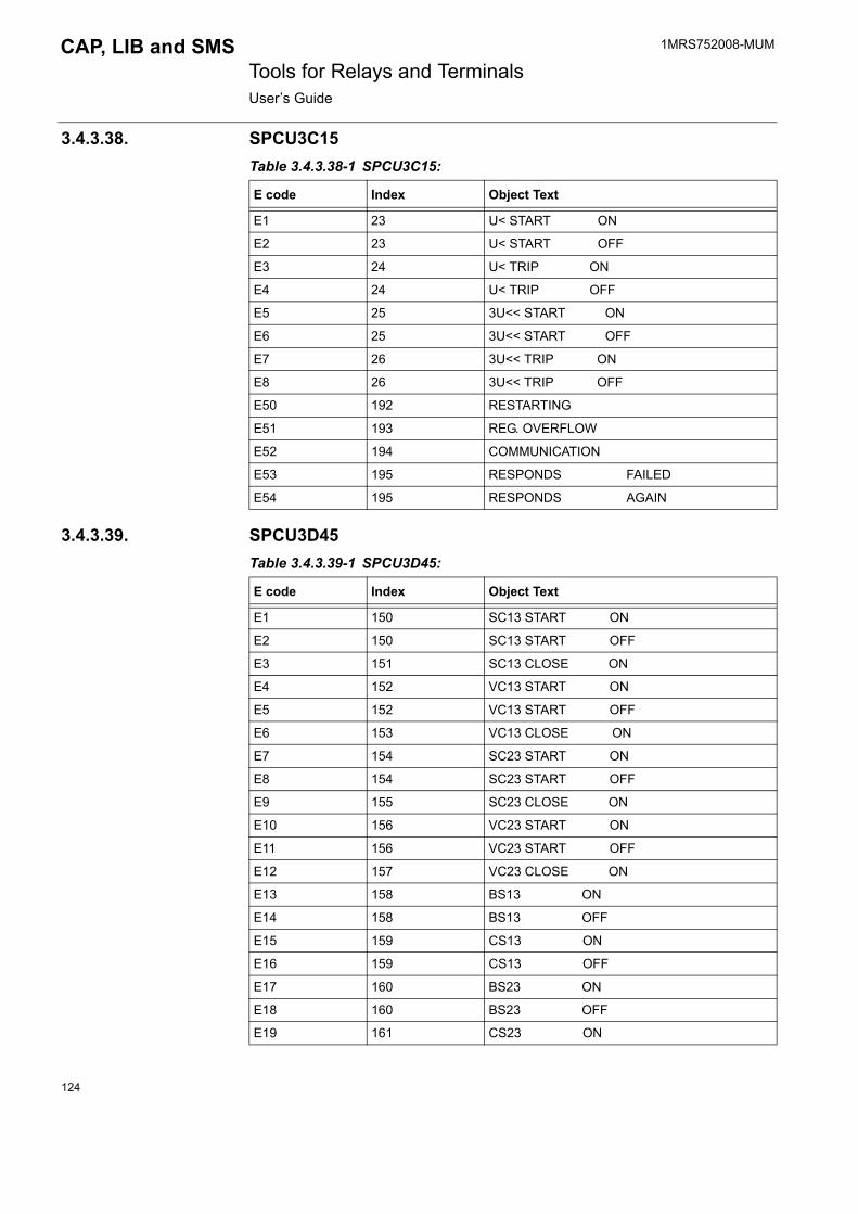
1MRS752008-MUM Tools for Relays and TerminalsUser�s Guide
CAP, LIB and SMS
3.4.3.38. SPCU3C15Table 3.4.3.38-1 SPCU3C15:
3.4.3.39. SPCU3D45Table 3.4.3.39-1 SPCU3D45:
E code Index Object Text
E1 23 U< START ON
E2 23 U< START OFF
E3 24 U< TRIP ON
E4 24 U< TRIP OFF
E5 25 3U<< START ON
E6 25 3U<< START OFF
E7 26 3U<< TRIP ON
E8 26 3U<< TRIP OFF
E50 192 RESTARTING
E51 193 REG. OVERFLOW
E52 194 COMMUNICATION
E53 195 RESPONDS FAILED
E54 195 RESPONDS AGAIN
E code Index Object Text
E1 150 SC13 START ON
E2 150 SC13 START OFF
E3 151 SC13 CLOSE ON
E4 152 VC13 START ON
E5 152 VC13 START OFF
E6 153 VC13 CLOSE ON
E7 154 SC23 START ON
E8 154 SC23 START OFF
E9 155 SC23 CLOSE ON
E10 156 VC23 START ON
E11 156 VC23 START OFF
E12 157 VC23 CLOSE ON
E13 158 BS13 ON
E14 158 BS13 OFF
E15 159 CS13 ON
E16 159 CS13 OFF
E17 160 BS23 ON
E18 160 BS23 OFF
E19 161 CS23 ON
124
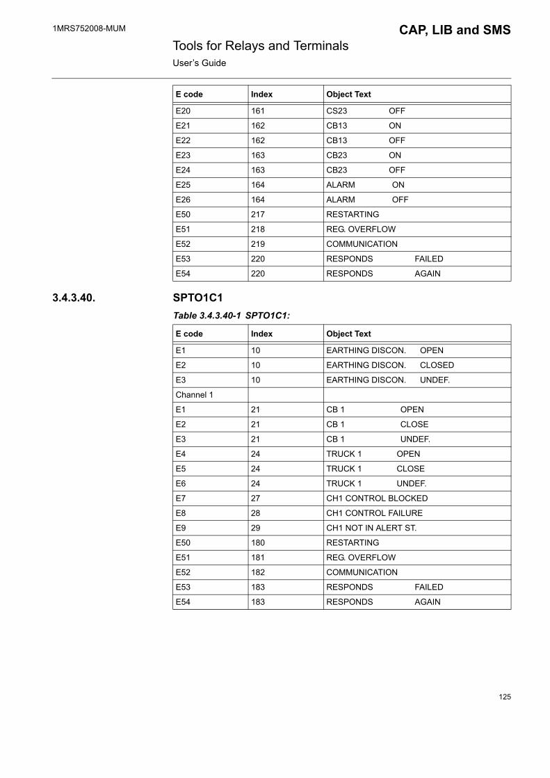
1MRS752008-MUM CAP, LIB and SMS Tools for Relays and TerminalsUser�s Guide
3.4.3.40. SPTO1C1Table 3.4.3.40-1 SPTO1C1:
E20 161 CS23 OFF
E21 162 CB13 ON
E22 162 CB13 OFF
E23 163 CB23 ON
E24 163 CB23 OFF
E25 164 ALARM ON
E26 164 ALARM OFF
E50 217 RESTARTING
E51 218 REG. OVERFLOW
E52 219 COMMUNICATION
E53 220 RESPONDS FAILED
E54 220 RESPONDS AGAIN
E code Index Object Text
E code Index Object Text
E1 10 EARTHING DISCON. OPEN
E2 10 EARTHING DISCON. CLOSED
E3 10 EARTHING DISCON. UNDEF.
Channel 1
E1 21 CB 1 OPEN
E2 21 CB 1 CLOSE
E3 21 CB 1 UNDEF.
E4 24 TRUCK 1 OPEN
E5 24 TRUCK 1 CLOSE
E6 24 TRUCK 1 UNDEF.
E7 27 CH1 CONTROL BLOCKED
E8 28 CH1 CONTROL FAILURE
E9 29 CH1 NOT IN ALERT ST.
E50 180 RESTARTING
E51 181 REG. OVERFLOW
E52 182 COMMUNICATION
E53 183 RESPONDS FAILED
E54 183 RESPONDS AGAIN
125
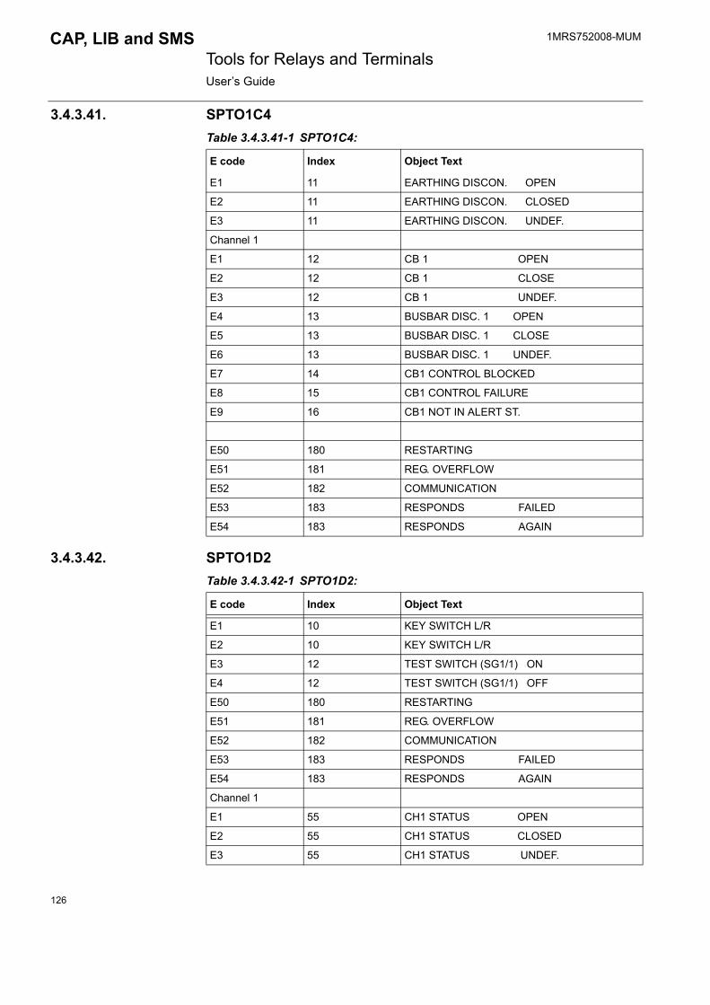
1MRS752008-MUM Tools for Relays and TerminalsUser�s Guide
CAP, LIB and SMS
3.4.3.41. SPTO1C4Table 3.4.3.41-1 SPTO1C4:
3.4.3.42. SPTO1D2Table 3.4.3.42-1 SPTO1D2:
E code Index Object Text
E1 11 EARTHING DISCON. OPEN
E2 11 EARTHING DISCON. CLOSED
E3 11 EARTHING DISCON. UNDEF.
Channel 1
E1 12 CB 1 OPEN
E2 12 CB 1 CLOSE
E3 12 CB 1 UNDEF.
E4 13 BUSBAR DISC. 1 OPEN
E5 13 BUSBAR DISC. 1 CLOSE
E6 13 BUSBAR DISC. 1 UNDEF.
E7 14 CB1 CONTROL BLOCKED
E8 15 CB1 CONTROL FAILURE
E9 16 CB1 NOT IN ALERT ST.
E50 180 RESTARTING
E51 181 REG. OVERFLOW
E52 182 COMMUNICATION
E53 183 RESPONDS FAILED
E54 183 RESPONDS AGAIN
E code Index Object Text
E1 10 KEY SWITCH L/R
E2 10 KEY SWITCH L/R
E3 12 TEST SWITCH (SG1/1) ON
E4 12 TEST SWITCH (SG1/1) OFF
E50 180 RESTARTING
E51 181 REG. OVERFLOW
E52 182 COMMUNICATION
E53 183 RESPONDS FAILED
E54 183 RESPONDS AGAIN
Channel 1
E1 55 CH1 STATUS OPEN
E2 55 CH1 STATUS CLOSED
E3 55 CH1 STATUS UNDEF.
126

1MRS752008-MUM CAP, LIB and SMS Tools for Relays and TerminalsUser�s Guide
E4 55 CH1 STATUS UNDEF.
E5 59 CH1 OPEN ACTIVATED
E6 59 CH1 OPEN RESET
E7 61 CH1 CLOSE ACTIVATED
E8 61 CH1 CLOSE RESET
E9 63 CH1 ACTIV. INHIB.
E10 64 CH1 ACTIV. FAILED
E11 65 CH1 ATTEMPT TO ACTIV. WITHOUT SEL.
Channel 2
E1 66 CH2 STATUS OPEN
E2 66 CH2 STATUS CLOSED
E3 66 CH2 STATUS UNDEF.
E4 66 CH2 STATUS UNDEF.
E5 70 CH2 OPEN ACTIVATED
E6 70 CH2 OPEN RESET
E7 72 CH2 CLOSE ACTIVATED
E8 72 CH2 CLOSE RESET
E9 74 CH2 ACTIV. INHIB.
E10 75 CH2 ACTIV. FAILED
E11 76 CH2 ATTEMPT TO ACTIV. WITHOUT SEL.
Channel 3
E1 77 CH3 STATUS OPEN
E2 77 CH3 STATUS CLOSED
E3 77 CH3 STATUS UNDEF.
E4 77 CH3 STATUS UNDEF.
E5 81 CH3 OPEN ACTIVATED
E6 81 CH3 OPEN RESET
E7 83 CH3 CLOSE ACTIVATED
E8 83 CH3 CLOSE RESET
E9 85 CH3 ACTIV. INHIB.
E10 86 CH3 ACTIV. FAILED
E11 87 CH3 ATTEMPT TO ACTIV. WITHOUT SEL.
Channel 4
E1 88 CH4 INPUT ACTIVATED
E2 88 CH4 INPUT RESET
E3 90 CH4 SIGNAL 1 .. 3 ACTIVATED
E4 90 CH4 SIGNAL 1 .. 3 RESET
Channel 5
E1 92 CH5 INPUT ACTIVATED
E code Index Object Text
127

1MRS752008-MUM Tools for Relays and TerminalsUser�s Guide
CAP, LIB and SMS
E2 92 CH5 INPUT RESET
E3 94 CH5 SIGNAL 1 .. 3 ACTIVATED
E4 94 CH5 SIGNAL 1 .. 3 RESET
Channel 6
E1 96 CH6 INPUT ACTIVATED
E2 96 CH6 INPUT RESET
E3 98 CH6 SIGNAL 1 .. 3 ACTIVATED
E4 98 CH6 SIGNAL 1 .. 3 RESET
Channel 7
E1 100 CH7 INPUT ACTIVATED
E2 100 CH7 INPUT RESET
E3 102 CH7 SIGNAL 1 .. 3 ACTIVATED
E4 102 CH7 SIGNAL 1 .. 3 RESET
Channel 8
E1 104 CH8 INPUT ACTIVATED
E2 104 CH8 INPUT RESET
E3 106 CH8 SIGNAL 1 .. 3 ACTIVATED
E4 106 CH8 SIGNAL 1 .. 3 RESET
Channel 9
E1 108 CH9 INPUT ACTIVATED
E2 108 CH9 INPUT RESET
E3 110 CH9 SIGNAL 1 .. 3 ACTIVATED
E4 110 CH9 SIGNAL 1 .. 3 RESET
Channel 10
E1 112 CH10 INPUT ACTIVATED
E2 112 CH10 INPUT RESET
E3 114 CH10 SIGNAL 1 .. 3 ACTIVATED
E4 114 CH10 SIGNAL 1 .. 3 RESET
Channel 11
E1 116 CH11 INPUT ACTIVATED
E2 116 CH11 INPUT RESET
E3 118 CH11 SIGNAL 1 .. 3 ACTIVATED
E4 118 CH11 SIGNAL 1 .. 3 RESET
Channel 12
E1 120 CH12 INPUT ACTIVATED
E2 120 CH12 INPUT RESET
E3 122 CH12 SIGNAL 1 .. 3 ACTIVATED
E4 122 CH12 SIGNAL 1 .. 3 RESET
Channel 13
E code Index Object Text
128

1MRS752008-MUM CAP, LIB and SMS Tools for Relays and TerminalsUser�s Guide
3.4.3.43. SPTO1D5Table 3.4.3.43-1 SPTO1D5:
E1 124 CH13 INPUT ACTIVATED
E2 124 CH13 INPUT RESET
E3 126 CH13 SIGNAL 1 .. 3 ACTIVATED
E4 126 CH13 SIGNAL 1 .. 3 RESET
E code Index Object Text
E code Index Object Text
E1 20 KEY SWITCH L/R
E2 20 KEY SWITCH L/R
E3 21 TEST SWITCH (SG1/1) ON
E4 21 TEST SWITCH (SG1/1) OFF
E50 184 RESTARTING
E51 185 REG. OVERFLOW
E52 186 COMMUNICATION
E53 187 RESPONDS FAILED
E54 187 RESPONDS AGAIN
Channel 1
E1 22 CH1 STATUS OPEN
E2 22 CH1 STATUS CLOSED
E3 22 CH1 STATUS UNDEF.
E4 22 CH1 STATUS UNDEF.
E5 23 CH1 OPEN ACTIVATED
E6 23 CH1 OPEN RESET
E7 24 CH1 CLOSE ACTIVATED
E8 24 CH1 CLOSE RESET
E9 25 CH1 ACTIV. INHIB.
E10 26 CH1 ACTIV. FAILED
E11 27 CH1 ATTEMPT TO ACTIV. WITHOUT SEL.
Channel 2
E1 28 CH2 STATUS OPEN
E2 28 CH2 STATUS CLOSED
E3 28 CH2 STATUS UNDEF.
E4 28 CH2 STATUS UNDEF.
E5 29 CH2 OPEN ACTIVATED
E6 29 CH2 OPEN RESET
E7 30 CH2 CLOSE ACTIVATED
E8 30 CH2 CLOSE RESET
129

1MRS752008-MUM Tools for Relays and TerminalsUser�s Guide
CAP, LIB and SMS
E9 31 CH2 ACTIV. INHIB.
E10 32 CH2 ACTIV. FAILED
E11 33 CH2 ATTEMPT TO ACTIV. WITHOUT SEL.
Channel 3
E1 34 CH3 STATUS OPEN
E2 34 CH3 STATUS CLOSED
E3 34 CH3 STATUS UNDEF.
E4 34 CH3 STATUS UNDEF.
E5 35 CH3 OPEN ACTIVATED
E6 35 CH3 OPEN RESET
E7 36 CH3 CLOSE ACTIVATED
E8 36 CH3 CLOSE RESET
E9 37 CH3 ACTIV. INHIB.
E10 38 CH3 ACTIV. FAILED
E11 39 CH3 ATTEMPT TO ACTIV. WITHOUT SEL.
Channel 4
E1 40 CH4 INPUT ACTIVATED
E2 40 CH4 INPUT RESET
E3 41 CH4 SIGNAL 1 .. 3 ACTIVATED
E4 41 CH4 SIGNAL 1 .. 3 RESET
Channel 5
E1 42 CH5 INPUT ACTIVATED
E2 42 CH5 INPUT RESET
E3 43 CH5 SIGNAL 1 .. 3 ACTIVATED
E4 43 CH5 SIGNAL 1 .. 3 RESET
Channel 6
E1 44 CH6 INPUT ACTIVATED
E2 44 CH6 INPUT RESET
E3 45 CH6 SIGNAL 1 .. 3 ACTIVATED
E4 45 CH6 SIGNAL 1 .. 3 RESET
Channel 7
E1 46 CH7 INPUT ACTIVATED
E2 46 CH7 INPUT RESET
E3 47 CH7 SIGNAL 1 .. 3 ACTIVATED
E4 47 CH7 SIGNAL 1 .. 3 RESET
Channel 8
E1 48 CH8 INPUT ACTIVATED
E2 48 CH8 INPUT RESET
E3 49 CH8 SIGNAL 1 .. 3 ACTIVATED
E code Index Object Text
130

1MRS752008-MUM CAP, LIB and SMS Tools for Relays and TerminalsUser�s Guide
3.4.3.44. SPTO1D6Table 3.4.3.44-1 SPTO1D6:
E4 49 CH8 SIGNAL 1 .. 3 RESET
Channel 9
E1 50 CH9 INPUT ACTIVATED
E2 50 CH9 INPUT RESET
E3 51 CH9 SIGNAL 1 .. 3 ACTIVATED
E4 51 CH9 SIGNAL 1 .. 3 RESET
Channel 10
E1 52 CH10 INPUT ACTIVATED
E2 52 CH10 INPUT RESET
E3 53 CH10 SIGNAL 1 .. 3 ACTIVATED
E4 53 CH10 SIGNAL 1 .. 3 RESET
Channel 11
E1 54 CH11 INPUT ACTIVATED
E2 54 CH11 INPUT RESET
E3 55 CH11 SIGNAL 1 .. 3 ACTIVATED
E4 55 CH11 SIGNAL 1 .. 3 RESET
Channel 12
E1 56 CH12 INPUT ACTIVATED
E2 56 CH12 INPUT RESET
E3 57 CH12 SIGNAL 1 .. 3 ACTIVATED
E4 57 CH12 SIGNAL 1 .. 3 RESET
Channel 13
E1 58 CH13 INPUT ACTIVATED
E2 58 CH13 INPUT RESET
E3 59 CH13 SIGNAL 1 .. 3 ACTIVATED
E4 59 CH13 SIGNAL 1 .. 3 RESET
E code Index Object Text
E code Index Object Text
E1 10 KEY SWITCH L/R
E2 10 KEY SWITCH L/R
E3 12 TEST SWITCH (SG1/1) ON
E4 12 TEST SWITCH (SG1/1) OFF
E5 14 SWICH (SG1/2) ON
E6 14 SWICH (SG1/2) OFF
E7 16 TRIP CIRCUIT FAILURE
E8 16 TRIP CIRCUIT FAILURE RESET
131
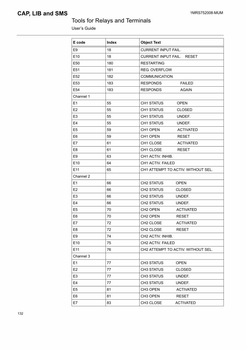
1MRS752008-MUM Tools for Relays and TerminalsUser�s Guide
CAP, LIB and SMS
E9 18 CURRENT INPUT FAIL.
E10 18 CURRENT INPUT FAIL. RESET
E50 180 RESTARTING
E51 181 REG. OVERFLOW
E52 182 COMMUNICATION
E53 183 RESPONDS FAILED
E54 183 RESPONDS AGAIN
Channel 1
E1 55 CH1 STATUS OPEN
E2 55 CH1 STATUS CLOSED
E3 55 CH1 STATUS UNDEF.
E4 55 CH1 STATUS UNDEF.
E5 59 CH1 OPEN ACTIVATED
E6 59 CH1 OPEN RESET
E7 61 CH1 CLOSE ACTIVATED
E8 61 CH1 CLOSE RESET
E9 63 CH1 ACTIV. INHIB.
E10 64 CH1 ACTIV. FAILED
E11 65 CH1 ATTEMPT TO ACTIV. WITHOUT SEL.
Channel 2
E1 66 CH2 STATUS OPEN
E2 66 CH2 STATUS CLOSED
E3 66 CH2 STATUS UNDEF.
E4 66 CH2 STATUS UNDEF.
E5 70 CH2 OPEN ACTIVATED
E6 70 CH2 OPEN RESET
E7 72 CH2 CLOSE ACTIVATED
E8 72 CH2 CLOSE RESET
E9 74 CH2 ACTIV. INHIB.
E10 75 CH2 ACTIV. FAILED
E11 76 CH2 ATTEMPT TO ACTIV. WITHOUT SEL.
Channel 3
E1 77 CH3 STATUS OPEN
E2 77 CH3 STATUS CLOSED
E3 77 CH3 STATUS UNDEF.
E4 77 CH3 STATUS UNDEF.
E5 81 CH3 OPEN ACTIVATED
E6 81 CH3 OPEN RESET
E7 83 CH3 CLOSE ACTIVATED
E code Index Object Text
132
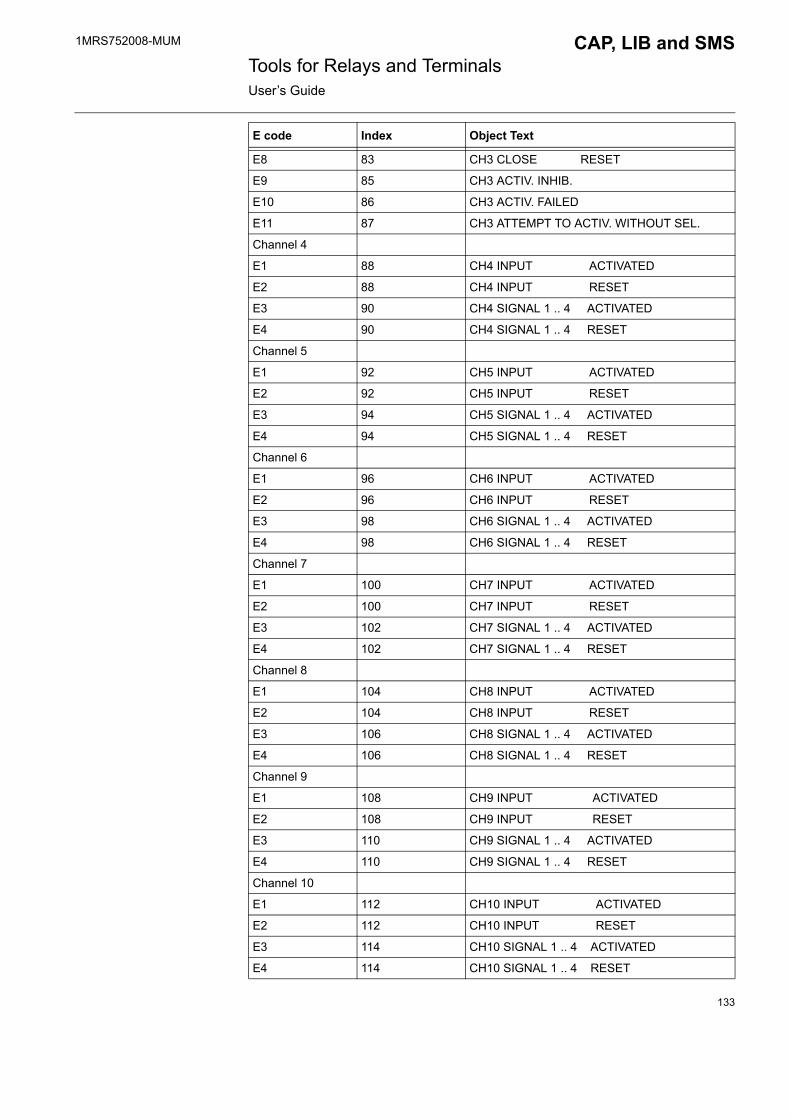
1MRS752008-MUM CAP, LIB and SMS Tools for Relays and TerminalsUser�s Guide
E8 83 CH3 CLOSE RESET
E9 85 CH3 ACTIV. INHIB.
E10 86 CH3 ACTIV. FAILED
E11 87 CH3 ATTEMPT TO ACTIV. WITHOUT SEL.
Channel 4
E1 88 CH4 INPUT ACTIVATED
E2 88 CH4 INPUT RESET
E3 90 CH4 SIGNAL 1 .. 4 ACTIVATED
E4 90 CH4 SIGNAL 1 .. 4 RESET
Channel 5
E1 92 CH5 INPUT ACTIVATED
E2 92 CH5 INPUT RESET
E3 94 CH5 SIGNAL 1 .. 4 ACTIVATED
E4 94 CH5 SIGNAL 1 .. 4 RESET
Channel 6
E1 96 CH6 INPUT ACTIVATED
E2 96 CH6 INPUT RESET
E3 98 CH6 SIGNAL 1 .. 4 ACTIVATED
E4 98 CH6 SIGNAL 1 .. 4 RESET
Channel 7
E1 100 CH7 INPUT ACTIVATED
E2 100 CH7 INPUT RESET
E3 102 CH7 SIGNAL 1 .. 4 ACTIVATED
E4 102 CH7 SIGNAL 1 .. 4 RESET
Channel 8
E1 104 CH8 INPUT ACTIVATED
E2 104 CH8 INPUT RESET
E3 106 CH8 SIGNAL 1 .. 4 ACTIVATED
E4 106 CH8 SIGNAL 1 .. 4 RESET
Channel 9
E1 108 CH9 INPUT ACTIVATED
E2 108 CH9 INPUT RESET
E3 110 CH9 SIGNAL 1 .. 4 ACTIVATED
E4 110 CH9 SIGNAL 1 .. 4 RESET
Channel 10
E1 112 CH10 INPUT ACTIVATED
E2 112 CH10 INPUT RESET
E3 114 CH10 SIGNAL 1 .. 4 ACTIVATED
E4 114 CH10 SIGNAL 1 .. 4 RESET
E code Index Object Text
133

1MRS752008-MUM Tools for Relays and TerminalsUser�s Guide
CAP, LIB and SMS
3.4.3.45. SPTO2C2Table 3.4.3.45-1 SPTO2C2:
Channel 11
E1 116 CH11 INPUT ACTIVATED
E2 116 CH11 INPUT RESET
E3 118 CH11 SIGNAL 1 .. 4 ACTIVATED
E4 118 CH11 SIGNAL 1 .. 4 RESET
Channel 12
E1 120 CH12 INPUT ACTIVATED
E2 120 CH12 INPUT RESET
E3 122 CH12 SIGNAL 1 .. 4 ACTIVATED
E4 122 CH12 SIGNAL 1 .. 4 RESET
Channel 13
E1 124 CH13 INPUT ACTIVATED
E2 124 CH13 INPUT RESET
E3 126 CH13 SIGNAL 1 .. 4 ACTIVATED
E4 126 CH13 SIGNAL 1 .. 4 RESET
E code Index Object Text
E code Index Object Text
E1 10 EARTHING DISCON. OPEN
E2 10 EARTHING DISCON. CLOSED
E3 10 EARTHING DISCON. UNDEF.
Channel 1
E1 21 CB 1 OPEN
E2 21 CB 1 CLOSE
E3 21 CB 1 UNDEF.
E4 24 TRUCK 1 OPEN
E5 24 TRUCK 1 CLOSE
E6 24 TRUCK 1 UNDEF.
E7 27 CH1 CONTROL BLOCKED
E8 28 CH1 CONTROL FAILURE
E9 29 CH1 NOT IN ALERT ST.
Channel 2
E1 30 CB 2 OPEN
E2 30 CB 2 CLOSE
E3 30 CB 2 UNDEF.
E4 33 TRUCK 2 OPEN
E5 33 TRUCK 2 CLOSE
134
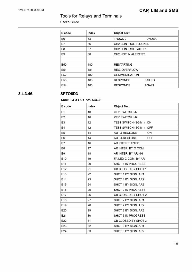
1MRS752008-MUM CAP, LIB and SMS Tools for Relays and TerminalsUser�s Guide
3.4.3.46. SPTO6D3Table 3.4.3.46-1 SPTO6D3:
E6 33 TRUCK 2 UNDEF.
E7 36 CH2 CONTROL BLOCKED
E8 37 CH2 CONTROL FAILURE
E9 38 CH2 NOT IN ALERT ST.
E50 180 RESTARTING
E51 181 REG. OVERFLOW
E52 182 COMMUNICATION
E53 183 RESPONDS FAILED
E54 183 RESPONDS AGAIN
E code Index Object Text
E code Index Object Text
E1 10 KEY SWITCH L/R
E2 10 KEY SWITCH L/R
E3 12 TEST SWITCH (SG1/1) ON
E4 12 TEST SWITCH (SG1/1) OFF
E5 14 AUTO-RECLOSE ON
E6 14 AUTO-RECLOSE OFF
E7 16 AR INTERRUPTED
E8 17 AR INTER. BY O COM.
E9 18 AR INTER. BY ARINH
E10 19 FAILED C COM. BY AR
E11 20 SHOT 1 IN PROGRESS
E12 21 CB CLOSED BY SHOT 1
E13 22 SHOT 1 BY SIGN. AR1
E14 23 SHOT 1 BY SIGN. AR2
E15 24 SHOT 1 BY SIGN. AR3
E16 25 SHOT 2 IN PROGRESS
E17 26 CB CLOSED BY SHOT 2
E18 27 SHOT 2 BY SIGN. AR1
E19 28 SHOT 2 BY SIGN. AR2
E20 29 SHOT 2 BY SIGN. AR3
E21 30 SHOT 3 IN PROGRESS
E22 31 CB CLOSED BY SHOT 3
E23 32 SHOT 3 BY SIGN. AR1
E24 33 SHOT 3 BY SIGN. AR2
135

1MRS752008-MUM Tools for Relays and TerminalsUser�s Guide
CAP, LIB and SMS
E25 34 SHOT 3 BY SIGN. AR3
E26 35 SHOT 4 IN PROGRESS
E27 36 CB CLOSED BY SHOT 4
E28 37 SHOT 4 BY SIGN. AR1
E29 38 SHOT 4 BY SIGN. AR2
E30 39 SHOT 4 BY SIGN. AR3
E31 40 SHOT 5 IN PROGRESS
E32 41 CB CLOSED BY SHOT 5
E33 42 SHOT 5 BY SIGN. AR1
E34 43 SHOT 5 BY SIGN. AR2
E35 44 SHOT 5 BY SIGN. AR3
E36 45 FINAL TRIP BY AR1
E37 46 FINAL TRIP BY AR2
E38 47 FINAL TRIP BY AR3
E39 48 FINAL TRIP BY H-SET
E40 49 FINAL TRIP BY L-SET
E41 50 FINAL TRIP BY E/F
E50 180 RESTARTING
E51 181 REG. OVERFLOW
E52 182 COMMUNICATION
E53 183 RESPONDS FAILED
E54 183 RESPONDS AGAIN
Channel 1
E1 55 CH1 STATUS OPEN
E2 55 CH1 STATUS CLOSED
E3 55 CH1 STATUS UNDEF.
E4 55 CH1 STATUS UNDEF.
E5 59 CH1 OPEN ACTIVATED
E6 59 CH1 OPEN RESET
E7 61 CH1 CLOSE ACTIVATED
E8 61 CH1 CLOSE RESET
E9 63 CH1 ACTIV. INHIB.
E10 64 CH1 ACTIV. FAILED
E11 65 CH1 ATTEMPT TO ACTIV. WITHOUT SEL.
Channel 2
E1 66 CH2 STATUS OPEN
E2 66 CH2 STATUS CLOSED
E3 66 CH2 STATUS UNDEF.
E4 66 CH2 STATUS UNDEF.
E code Index Object Text
136
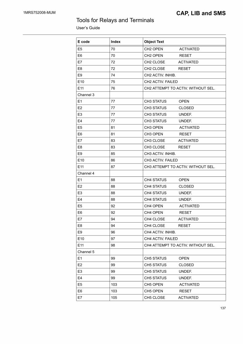
1MRS752008-MUM CAP, LIB and SMS Tools for Relays and TerminalsUser�s Guide
E5 70 CH2 OPEN ACTIVATED
E6 70 CH2 OPEN RESET
E7 72 CH2 CLOSE ACTIVATED
E8 72 CH2 CLOSE RESET
E9 74 CH2 ACTIV. INHIB.
E10 75 CH2 ACTIV. FAILED
E11 76 CH2 ATTEMPT TO ACTIV. WITHOUT SEL.
Channel 3
E1 77 CH3 STATUS OPEN
E2 77 CH3 STATUS CLOSED
E3 77 CH3 STATUS UNDEF.
E4 77 CH3 STATUS UNDEF.
E5 81 CH3 OPEN ACTIVATED
E6 81 CH3 OPEN RESET
E7 83 CH3 CLOSE ACTIVATED
E8 83 CH3 CLOSE RESET
E9 85 CH3 ACTIV. INHIB.
E10 86 CH3 ACTIV. FAILED
E11 87 CH3 ATTEMPT TO ACTIV. WITHOUT SEL.
Channel 4
E1 88 CH4 STATUS OPEN
E2 88 CH4 STATUS CLOSED
E3 88 CH4 STATUS UNDEF.
E4 88 CH4 STATUS UNDEF.
E5 92 CH4 OPEN ACTIVATED
E6 92 CH4 OPEN RESET
E7 94 CH4 CLOSE ACTIVATED
E8 94 CH4 CLOSE RESET
E9 96 CH4 ACTIV. INHIB.
E10 97 CH4 ACTIV. FAILED
E11 98 CH4 ATTEMPT TO ACTIV. WITHOUT SEL.
Channel 5
E1 99 CH5 STATUS OPEN
E2 99 CH5 STATUS CLOSED
E3 99 CH5 STATUS UNDEF.
E4 99 CH5 STATUS UNDEF.
E5 103 CH5 OPEN ACTIVATED
E6 103 CH5 OPEN RESET
E7 105 CH5 CLOSE ACTIVATED
E code Index Object Text
137
1MRS752008-MUM Tools for Relays and TerminalsUser�s Guide
CAP, LIB and SMS
E8 105 CH5 CLOSE RESET
E9 107 CH5 ACTIV. INHIB.
E10 108 CH5 ACTIV. FAILED
E11 109 CH5 ATTEMPT TO ACTIV. WITHOUT SEL.
Channel 6
E1 110 CH6 STATUS OPEN
E2 110 CH6 STATUS CLOSED
E3 110 CH6 STATUS UNDEF.
E4 110 CH6 STATUS UNDEF.
E5 114 CH6 OPEN ACTIVATED
E6 114 CH6 OPEN RESET
E7 116 CH6 CLOSE ACTIVATED
E8 116 CH6 CLOSE RESET
E9 118 CH6 ACTIV. INHIB.
E10 119 CH6 ACTIV. FAILED
E11 120 CH6 ATTEMPT TO ACTIV. WITHOUT SEL.
Channel 7
E1 121 CH7 STATUS OPEN
E2 121 CH7 STATUS CLOSED
E3 121 CH7 STATUS UNDEF.
E4 121 CH7 STATUS UNDEF.
E5 125 CH7 OPEN ACTIVATED
E6 125 CH7 OPEN RESET
E7 127 CH7 CLOSE ACTIVATED
E8 127 CH7 CLOSE RESET
E9 129 CH7 ACTIV. INHIB.
E10 130 CH7 ACTIV. FAILED
E11 131 CH7 ATTEMPT TO ACTIV. WITHOUT SEL.
Channel 8
E1 132 CH8 INPUT ACTIVATED
E2 132 CH8 INPUT RESET
E3 134 CH8 SIGNAL 5 OR 6 ACTIVATED
E4 134 CH8 SIGNAL 5 OR 6 RESET
Channel 9
E1 136 CH9 INPUT ACTIVATED
E2 136 CH9 INPUT RESET
E3 138 CH9 SIGNAL 5 OR 6 ACTIVATED
E4 138 CH9 SIGNAL 5 OR 6 RESET
Channel 10
E code Index Object Text
138

1MRS752008-MUM CAP, LIB and SMS Tools for Relays and TerminalsUser�s Guide
E1 140 CH10 INPUT ACTIVATED
E2 140 CH10 INPUT RESET
E3 142 CH10 SIGNAL 5 OR 6 ACTIVATED
E4 142 CH10 SIGNAL 5 OR 6 RESET
Channel 11
E1 144 CH11 INPUT ACTIVATED
E2 144 CH11 INPUT RESET
E3 146 CH11 SIGNAL 5 OR 6 ACTIVATED
E4 146 CH11 SIGNAL 5 OR 6 RESET
Channel 12
E1 148 CH12 INPUT ACTIVATED
E2 148 CH12 INPUT RESET
E3 150 CH12 SIGNAL 5 OR 6 ACTIVATED
E4 150 CH12 SIGNAL 5 OR 6 RESET
Channel 13
E1 152 CH13 INPUT ACTIVATED
E2 152 CH13 INPUT RESET
E3 154 CH13 SIGNAL 5 OR 6 ACTIVATED
E4 154 CH13 SIGNAL 5 OR 6 RESET
Channel 14
E1 156 CH14 INPUT ACTIVATED
E2 156 CH14 INPUT RESET
E3 158 CH14 SIGNAL 5 OR 6 ACTIVATED
E4 158 CH14 SIGNAL 5 OR 6 RESET
Channel 15
E1 160 CH15 INPUT ACTIVATED
E2 160 CH15 INPUT RESET
E3 162 CH15 SIGNAL 5 OR 6 ACTIVATED
E4 162 CH15 SIGNAL 5 OR 6 RESET
Channel 16
E1 164 CH16 INPUT ACTIVATED
E2 164 CH16 INPUT RESET
E3 166 CH16 SIGNAL 5 OR 6 ACTIVATED
E4 166 CH16 SIGNAL 5 OR 6 RESET
Channel 17
E1 168 CH17 INPUT ACTIVATED
E2 168 CH17 INPUT RESET
E3 170 CH17 SIGNAL 5 OR 6 ACTIVATED
E4 170 CH17 SIGNAL 5 OR 6 RESET
E code Index Object Text
139
1MRS752008-MUM Tools for Relays and TerminalsUser�s Guide
CAP, LIB and SMS
3.4.3.47. SPTO12D4Table 3.4.3.47-1 SPTO12D4:
E code Index Object Text
E50 190 RESTARTING
E51 191 REG. OVERFLOW
E52 192 COMMUNICATION
E53 193 RESPONDS FAILED
E54 193 RESPONDS AGAIN
Channel 1
E1 63 CH1 STATUS CLOSED
E2 63 CH1 STATUS OPEN
E3 63 CH1 STATUS UNDEF.
E4 63 CH1 STATUS UNDEF.
Channel 2
E1 64 CH2 STATUS CLOSED
E2 64 CH2 STATUS OPEN
Channel 3
E1 65 CH3 STATUS CLOSED
E2 65 CH3 STATUS OPEN
E3 65 CH3 STATUS UNDEF.
E4 65 CH3 STATUS UNDEF.
Channel 4
E1 66 CH4 STATUS CLOSED
E2 66 CH4 STATUS OPEN
Channel 5
E1 67 CH5 STATUS CLOSED
E2 67 CH5 STATUS OPEN
E3 67 CH5 STATUS UNDEF.
E4 67 CH5 STATUS UNDEF.
Channel 6
E1 68 CH6 STATUS CLOSED
E2 68 CH6 STATUS OPEN
Channel 7
E1 69 CH7 STATUS CLOSED
E2 69 CH7 STATUS OPEN
E3 69 CH7 STATUS UNDEF.
E4 69 CH7 STATUS UNDEF.
Channel 8
E1 70 CH8 STATUS CLOSED
140

1MRS752008-MUM CAP, LIB and SMS Tools for Relays and TerminalsUser�s Guide
E2 70 CH8 STATUS OPEN
Channel 9
E1 71 CH9 STATUS CLOSED
E2 71 CH9 STATUS OPEN
E3 71 CH9 STATUS UNDEF.
E4 71 CH9 STATUS UNDEF.
Channel 10
E1 72 CH10 STATUS CLOSED
E2 72 CH10 STATUS OPEN
Channel 11
E1 73 CH11 STATUS CLOSED
E2 73 CH11 STATUS OPEN
E3 73 CH11 STATUS UNDEF.
E4 73 CH11 STATUS UNDEF.
Channel 12
E1 74 CH12 STATUS CLOSED
E2 74 CH12 STATUS OPEN
Channel 13
E1 75 CH13 STATUS CLOSED
E2 75 CH13 STATUS OPEN
E3 75 CH13 STATUS UNDEF.
E4 75 CH13 STATUS UNDEF.
Channel 14
E1 76 CH14 STATUS CLOSED
E2 76 CH14 STATUS OPEN
Channel 15
E1 77 CH15 STATUS CLOSED
E2 77 CH15 STATUS OPEN
E3 77 CH15 STATUS UNDEF.
E4 77 CH15 STATUS UNDEF.
Channel 16
E1 78 CH16 STATUS CLOSED
E2 78 CH16 STATUS OPEN
E code Index Object Text
141

1MRS752008-MUM Tools for Relays and TerminalsUser�s Guide
CAP, LIB and SMS
3.4.3.48. REC 501Table 3.4.3.48-1 REC 501:
E code Index Object Text
E1 11 INPUT I1
E2 11 INPUT I1
E3 12 INPUT I2
E4 12 INPUT I2
E5 13 INPUT I3
E6 13 INPUT I3
E7 14 INPUT I4
E8 14 INPUT I4
E10 15 INPUT I5
E11 15 INPUT I5
E12 16 BATTERY VOLTAGE LOW
E13 16 BATTERY VOLTAGE NORMAL
E14 17 POWER SUPPLY TEMP. HIGH
E15 17 POWER SUPPLY TEMP. NORMAL
E16 18 AUX. SUPPLY CONNECTION
E17 18 AUX. SUPPLY CONNECTION
E18 19 INTERMDT COUNTER 1 NEW VALUE
E19 20 INTERMDT COUNTER 2 NEW VALUE
E20 21 PERIOD COUNTER 1 NEW VALUE
E21 22 PERIOD COUNTER 2 NEW VALUE
E30 17 OUTPUT O1
E31 17 OUTPUT O1
E32 18 OUTPUT O2
E33 18 OUTPUT O2
E34 19 OUTPUT O3
E35 20 OUTPUT O3
E36 21 OUTPUT O4
E37 22 OUTPUT O4
Channel 1
E40 27 OBJECT 1 STATUS->10
E41 27 OBJECT 1 STATUS->01
E42 27 OBJECT 1 STATUS->11
E43 27 OBJECT 1 STATUS->00
E44 28 OBJECT 1,OPEN COMMAND
E45 29 OBJECT 1,CLOSE COMMAND
Channel 2
142
1MRS752008-MUM CAP, LIB and SMS Tools for Relays and TerminalsUser�s Guide
3.4.3.49. SPCF 1D15Table 3.4.3.49-1 SPCF 1D15:
E40 30 OBJECT 2 STATUS->10
E41 30 OBJECT 2 STATUS->01
E42 30 OBJECT 2 STATUS->11
E43 30 OBJECT 2 STATUS->00
E44 31 OBJECT 2,OPEN COMMAND
E45 32 OBJECT 2,CLOSE COMMAND
E50 180 RESTARTING
E51 181 REG. OVERFLOW
E52 182 COMMUNICATION
E53 183 RESPONDS FAILED
E54 183 RESPONDS AGAIN
E code Index Object Text
E code Index Object Text
E1 35 STAGE 1 ON
E2 35 STAGE 1 OFF
E3 36 STAGE 1 TIMER 1 TRIP ON
E4 36 STAGE 1 TIMER 1 TRIP OFF
E5 37 STAGE 1 TIMER 2 TRIP ON
E6 37 STAGE 1 TIMER 2 TRIP OFF
E7 38 STAGE 2 ON
E8 38 STAGE 2 OFF
E9 39 STAGE 2 TIMER 1 TRIP ON
E10 39 STAGE 2 TIMER 1 TRIP OFF
E11 40 STAGE 2 TIMER 2 TRIP ON
E12 40 STAGE 2 TIMER 2 TRIP OFF
E13 41 STAGE 3 ON
E14 41 STAGE 3 OFF
E15 42 STAGE 3 TIMER 1 TRIP ON
E16 42 STAGE 3 TIMER 1 TRIP OFF
E17 43 STAGE 3 TIMER 2 TRIP ON
E18 43 STAGE 3 TIMER 2 TRIP OFF
E19 44 STAGE 4 ON
E20 44 STAGE 4 OFF
E21 45 STAGE 4 TIMER 1 TRIP ON
E22 45 STAGE 4 TIMER 1 TRIP OFF
E23 46 STAGE 4 TIMER 2 TRIP ON
143

1MRS752008-MUM Tools for Relays and TerminalsUser�s Guide
CAP, LIB and SMS
3.4.4. Format pictures and status textsTable 3.4.4-1 Format pictures and status texts:
E24 46 STAGE 4 TIMER 2 TRIP OFF
E25 47 OUTPUT SS1 ON
E26 47 OUTPUT SS1 OFF
E27 48 OUTPUT SS2 ON
E28 48 OUTPUT SS2 OFF
E29 49 OUTPUT SS3 ON
E30 49 OUTPUT SS3 OFF
E31 50 OUTPUT SS4 ON
E32 50 OUTPUT SS4 OFF
E33 51 OUTPUT TS1 ON
E34 51 OUTPUT TS1 OFF
E35 52 OUTPUT TS2 ON
E36 52 OUTPUT TS2 OFF
E37 53 OUTPUT TS3 ON
E38 53 OUTPUT TS3 OFF
E39 54 OUTPUT TS4 ON
E40 54 OUTPUT TS4 OFF
E41 55 RECOVERY FUNCTION ON
E42 55 RECOVERY FUNCTION OFF
E43 56 RECOV.FUNC INTRRPTD
E44 57 RECOV.FUNC OPERATING
E45 58 RECOV.FUNC RESET
E50 185 RESTARTING
E51 186 REG. OVERFLOW
E52 187 COMMUNICATION
E53 188 RESPONDS FAILED
E54 188 RESPONDS AGAIN
E code Index Object Text
Filename Value Status text
FORM4FRALI.PIC 012345
NormalAlarmRemoteLocalOffOn
FORM4UMEV.PIC Unmapped event
144

1MRS752008-MUM CAP, LIB and SMS Tools for Relays and TerminalsUser�s Guide
4. SPACOM Relay Setting Tool
4.1. DescriptionThe SPACOM Relay Setting Tool is used for monitoring and setting parameter data of the SPACOM relays. This tool is used for relay units regarding parametrization.
4.1.1. Target systems� Relay units based on SPACOM object type
4.1.2. Features/options� On-line parametrization� Off-line parametrization� Upload/Download all parameters� Upload/Download group of parameters� Selection of setting group� Reset of registers� Authorization support in LIB 500/510� Printing� Comparison of relay and setting tool parameters
4.2. Tool environmentsDepending on software environment, the SPACOM Relay Setting Tool can be started in different ways:
� In LIB 510/MicroSCADA, the Relay Setting Tool can be started from the relay symbol (push button) in the station picture (see Fig. 4.2.1.-1).
� In CAP 501/505 and SMS 510, you can use a tree navigator and select a relay. After this a list of tools is displayed and you can double-click the item Relay Setting Tool (see Fig. 4.2.2.-1).
4.2.1. Starting from LIB 510 in MicroSCADAThe relay units are displayed as push buttons in station pictures as seen in Fig. 4.2.1.-1 (�push button�). The relay functions can also be installed to be selected from the control panel of the bay function.
145
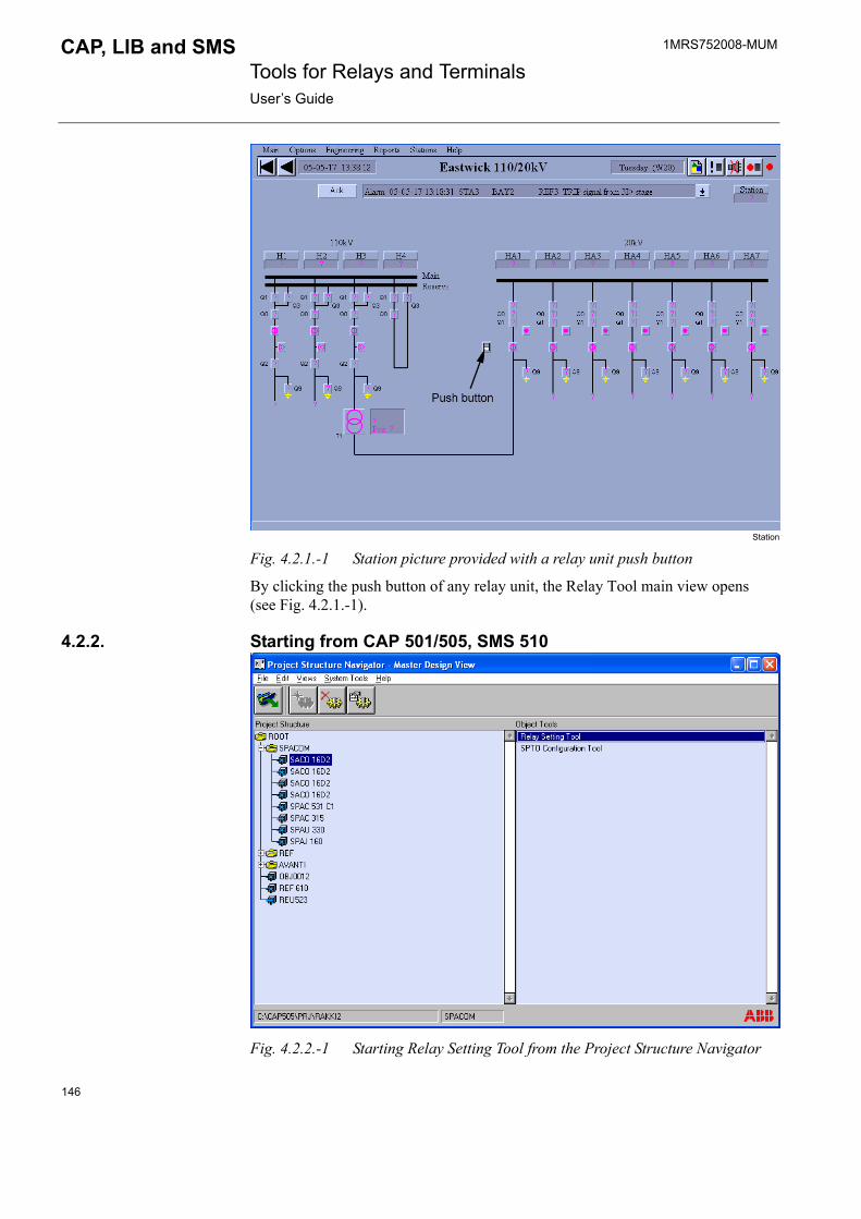
1MRS752008-MUM Tools for Relays and TerminalsUser�s Guide
CAP, LIB and SMS
Station
Fig. 4.2.1.-1 Station picture provided with a relay unit push button
By clicking the push button of any relay unit, the Relay Tool main view opens (see Fig. 4.2.1.-1).
4.2.2. Starting from CAP 501/505, SMS 510
Fig. 4.2.2.-1 Starting Relay Setting Tool from the Project Structure Navigator
146

1MRS752008-MUM CAP, LIB and SMS Tools for Relays and TerminalsUser�s Guide
4.3. Relay Setting Tool
4.3.1. Main view
MainViNr
Fig. 4.3.1.-1 Relay Setting Tool main overview
1. Title Bar2. Main Menu3. Toolbar4. Module Selection Box5. Tool Area6. Parameter Group List Box7. Status Bar
The Relay Setting Tool automatically selects the first module of the relay to the module list (see Fig. 4.3.1.-1, item 4) and the first parameter group item from the parameter group list (see Fig. 4.3.1.-1, item 6). After that the tool opens the data for selections.
The tool uses the internal parameter file (values.ini) for storing the parameter values. The parameter file is created with the default values by the relay configuration dialog when the relay is installed into the project structure. The Relay Setting Tool maintains the file. The parameter values are updated to the parameter file every time when uploading is performed. All the values displayed by the tool are read from the parameter file. For example, if the user uploads parameter values, they are first updated to the file and after that read from the file to the tool.
147
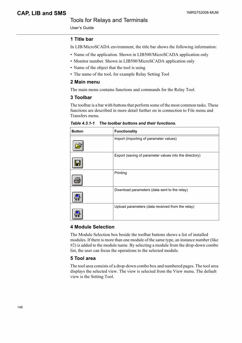
1MRS752008-MUM Tools for Relays and TerminalsUser�s Guide
CAP, LIB and SMS
1 Title barIn LIB/MicroSCADA environment, the title bar shows the following information:
� Name of the application. Shown in LIB500/MicroSCADA application only� Monitor number. Shown in LIB500/MicroSCADA application only� Name of the object that the tool is using� The name of the tool, for example Relay Setting Tool
2 Main menuThe main menu contains functions and commands for the Relay Tool.
3 ToolbarThe toolbar is a bar with buttons that perform some of the most common tasks. These functions are described in more detail further on in connection to File menu and Transfers menu.
Table 4.3.1-1 The toolbar buttons and their functions.
4 Module SelectionThe Module Selection box beside the toolbar buttons shows a list of installed modules. If there is more than one module of the same type, an instance number (like #2) is added to the module name. By selecting a module from the drop-down combo list, the user can focus the operations to the selected module.
5 Tool areaThe tool area consists of a drop-down combo box and numbered pages. The tool area displays the selected view. The view is selected from the View menu. The default view is the Setting Tool.
Button Functionality
Import (importing of parameter values)
Export (saving of parameter values into the directory)
Printing
Download parameters (data sent to the relay)
Upload parameters (data received from the relay)
148

1MRS752008-MUM CAP, LIB and SMS Tools for Relays and TerminalsUser�s Guide
The Relay Setting Tool (Settings, Registers, Setting Tool) is displayed on this part of the HSI. The Settings and Registers views present the most frequently used information from the relay. The Setting Tool function offers a complete tool for monitoring and configuring the relay.
6 Parameter Group List BoxThe Parameter Group List box shows a list of parameters and current values. Click the drop-down combo box to select the values you wish to change.
7 Status barThe status bar shows information about the current status of the tool. The status bar has the following fields:
1. Information about the relay type, e.g. SPAC 5312. Upload status of the parameters. The status may be:� Uploaded 0000-00-00 00:00, when the parameter values of the selected
parameter group/view have been read from the default file or they have been imported.
� Uploaded 1999-10-08 10:17, when the parameter values of the selected parameter group/view have been read from the relay.
4.4. Using Relay Setting ToolThis section describes the submenus and commands that are available in the Relay Tool menus.
4.4.1. File menuThe File menu contains the functions belonging to the file handling.
Fig. 4.4.1.-1 The File menu
4.4.1.1. ImportingWith the help of the Import dialog (see Fig. 4.4.1.1.-1) it is possible to read parameter values from the selected file that will be used by the Relay Setting Tool. The imported parameter values replace the old values in the parameter file.
To import parameters, select the desired file and directory and click Open. To exit the dialog without executing the importing process, click Cancel.
Access: Authorization level 2.
149

1MRS752008-MUM Tools for Relays and TerminalsUser�s Guide
CAP, LIB and SMS
Fig. 4.4.1.1.-1 Import dialog
4.4.1.2. ExportingParameter values can be saved into files with the help of the Export dialog (see Fig. 4.4.1.2.-1). To export parameter values, select the desired file and directory by clicking the relevant fields. Enter the name of the directory/file into the field named Save as, and click the Save button. To exit the dialog without executing the exporting operation, click Cancel.
Access: Authorization level 2.
150

1MRS752008-MUM CAP, LIB and SMS Tools for Relays and TerminalsUser�s Guide
Fig. 4.4.1.2.-1 Export dialog
4.4.1.3. Page SetupBefore printing, the margins (Top, Left, Bottom, Right) can be defined. The Page Setup dialog (see Fig. 4.4.1.3.-1) can be found by clicking the Page Setup option in the File menu. The margins can be set in this dialog by selecting the appropriate values on the list. Confirm the set margins by clicking OK. Click Cancel to cancel.
PageSetDlg.tif
Fig. 4.4.1.3.-1 Page Setup dialog
151
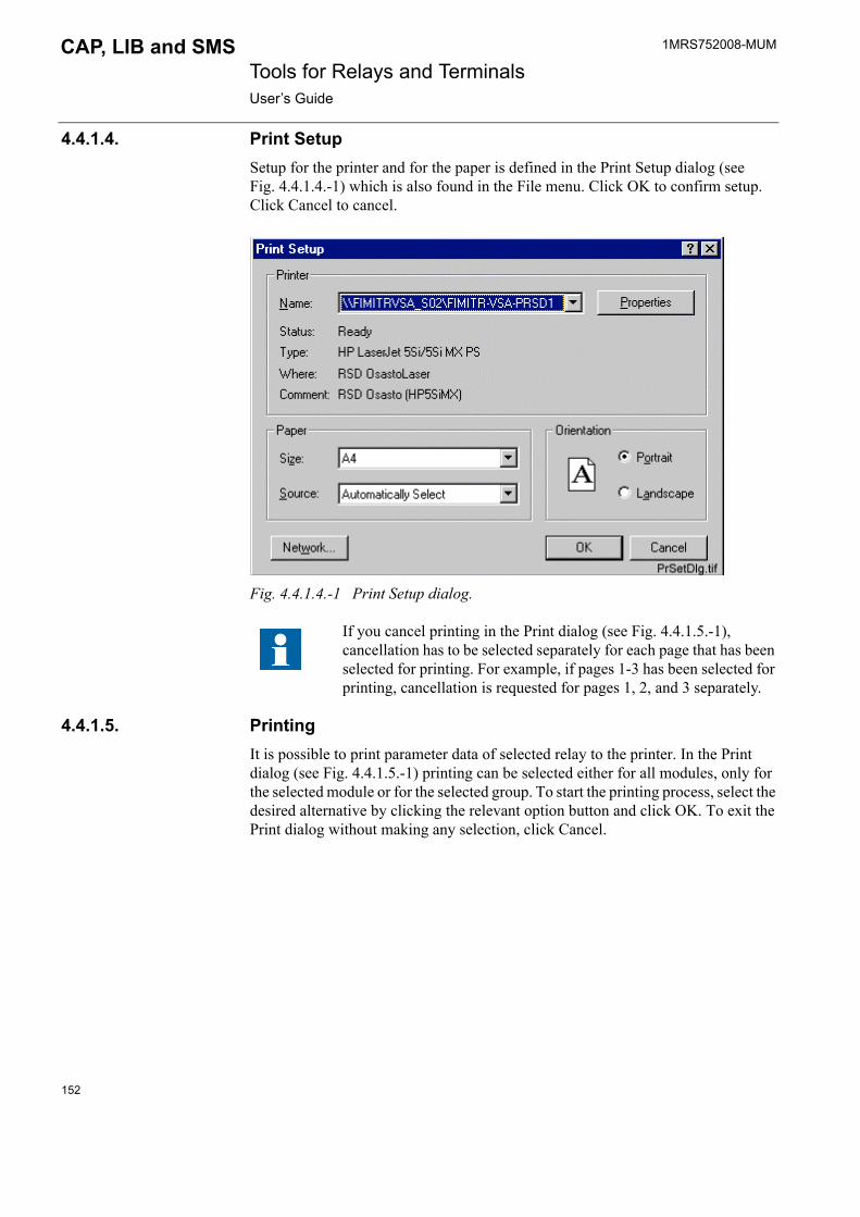
1MRS752008-MUM Tools for Relays and TerminalsUser�s Guide
CAP, LIB and SMS
4.4.1.4. Print SetupSetup for the printer and for the paper is defined in the Print Setup dialog (see Fig. 4.4.1.4.-1) which is also found in the File menu. Click OK to confirm setup. Click Cancel to cancel.
Fig. 4.4.1.4.-1 Print Setup dialog.
4.4.1.5. PrintingIt is possible to print parameter data of selected relay to the printer. In the Print dialog (see Fig. 4.4.1.5.-1) printing can be selected either for all modules, only for the selected module or for the selected group. To start the printing process, select the desired alternative by clicking the relevant option button and click OK. To exit the Print dialog without making any selection, click Cancel.
If you cancel printing in the Print dialog (see Fig. 4.4.1.5.-1), cancellation has to be selected separately for each page that has been selected for printing. For example, if pages 1-3 has been selected for printing, cancellation is requested for pages 1, 2, and 3 separately.
152
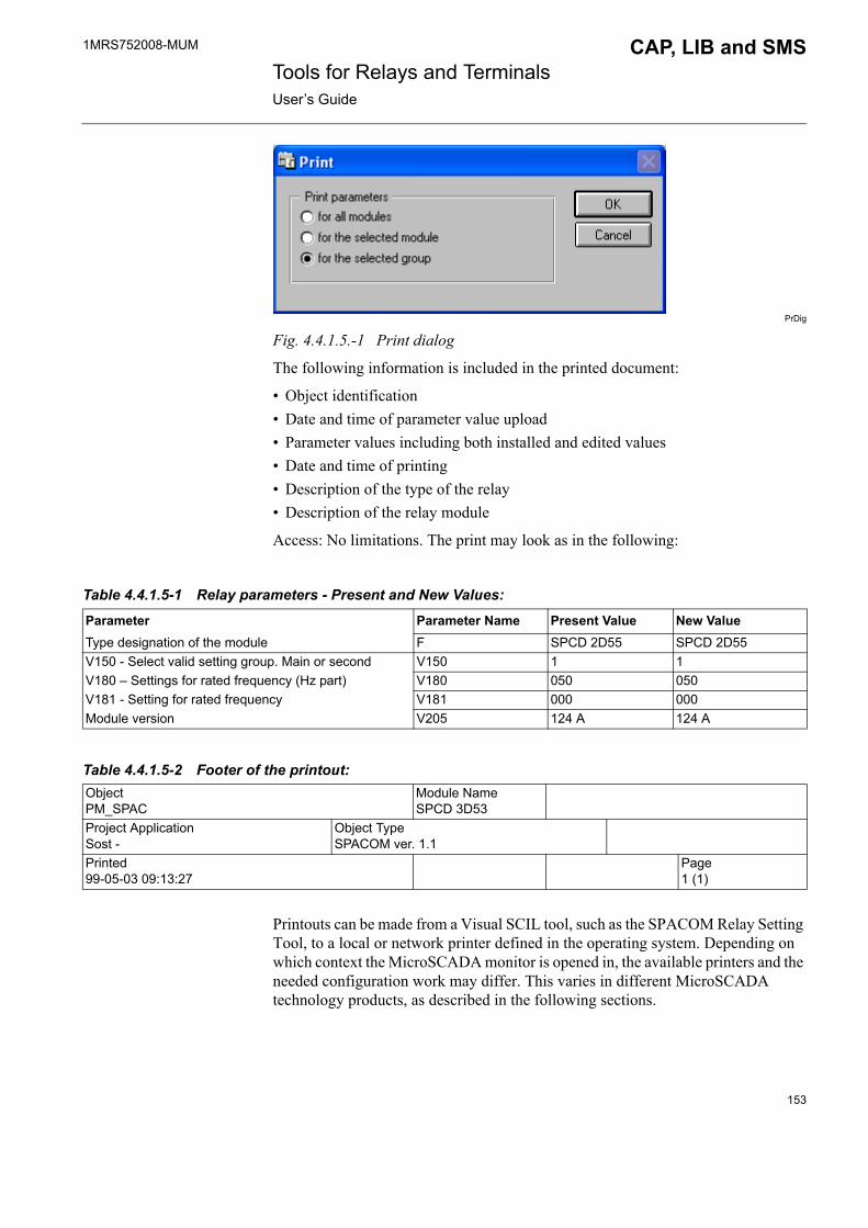
1MRS752008-MUM CAP, LIB and SMS Tools for Relays and TerminalsUser�s Guide
PrDig
Fig. 4.4.1.5.-1 Print dialog
The following information is included in the printed document:
� Object identification � Date and time of parameter value upload� Parameter values including both installed and edited values� Date and time of printing� Description of the type of the relay� Description of the relay module
Access: No limitations. The print may look as in the following:
Printouts can be made from a Visual SCIL tool, such as the SPACOM Relay Setting Tool, to a local or network printer defined in the operating system. Depending on which context the MicroSCADA monitor is opened in, the available printers and the needed configuration work may differ. This varies in different MicroSCADA technology products, as described in the following sections.
Table 4.4.1.5-1 Relay parameters - Present and New Values:
Parameter Parameter Name Present Value New ValueType designation of the module F SPCD 2D55 SPCD 2D55V150 - Select valid setting group. Main or second V150 1 1V180 � Settings for rated frequency (Hz part) V180 050 050V181 - Setting for rated frequency V181 000 000Module version V205 124 A 124 A
Table 4.4.1.5-2 Footer of the printout:ObjectPM_SPAC
Module NameSPCD 3D53
Project ApplicationSost -
Object TypeSPACOM ver. 1.1
Printed99-05-03 09:13:27
Page1 (1)
153

1MRS752008-MUM Tools for Relays and TerminalsUser�s Guide
CAP, LIB and SMS
CAP 501, CAP 505 and SMS 510In CAP 501, CAP 505 and SMS 510 tools are always opened in accordance with the current user that has logged in to the operating system. In this case, all the printers that are provided by the operating system for the user are available also for printing from SPACOM Relay Setting Tools.
LIB 510/MicroSCADAIn these products a monitor is by default opened in accordance with the MicroSCADA user, i.e. the user with the user name �MicroSCADA�. In this case only local printers can be used for printing from SPACOM Relay Setting Tool. Local printers are:� Printers connected directly to computer's serial or parallel port� Network printers defined as local port
The procedure how to define a network printer as local port is described in the SYS 500 System Management User�s Guide.
If a monitor is opened from a command prompt or from SCIL with an operating system call, it can be opened to the context of the current operating system user. This requires that the command line option start_as_logon_user is used when opening the monitor. Further details for the opening of monitors can be found in the SYS 500 System Management User�s Guide. When a monitor is opened in accordance with of the current operating system user, printers can be used as in CAP 501, CAP 505 and SMS 510.
4.4.1.6. ExitBy selecting the Exit option, the program exits the Relay Setting Tool and returns to the Project Structure Navigator (see Fig. 4.2.2.-1) in CAP 501/505 and SMS 510 environment. In LIB 510/MicroSCADA environment, the Relay Setting Tool window is closed.
4.4.2. View menuThe parameter data can be viewed and set in the view menus. The View menu contains three views (Settings, Registers, Setting Tool), which each shows a different subset of the parameters of the selected module.
By default, when the SPACOM Relay Setting Tool is started, the Setting Tool view is opened to the tool area. The check mark in the View menu indicates which view is currently selected (see Fig. 4.4.2.-1).
Fig. 4.4.2.-1 View menu
When local printers are used, the MicroSCADA user should have access to these printers.
154
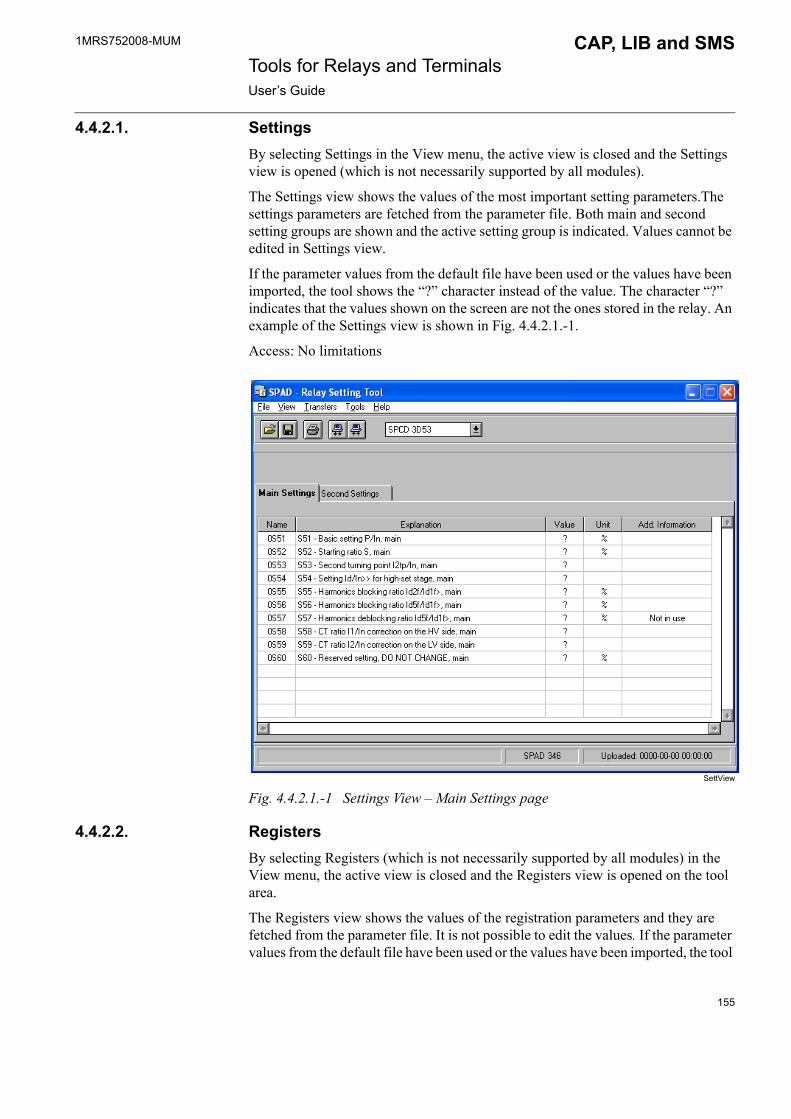
1MRS752008-MUM CAP, LIB and SMS Tools for Relays and TerminalsUser�s Guide
4.4.2.1. SettingsBy selecting Settings in the View menu, the active view is closed and the Settings view is opened (which is not necessarily supported by all modules).
The Settings view shows the values of the most important setting parameters.The settings parameters are fetched from the parameter file. Both main and second setting groups are shown and the active setting group is indicated. Values cannot be edited in Settings view.
If the parameter values from the default file have been used or the values have been imported, the tool shows the �?� character instead of the value. The character �?� indicates that the values shown on the screen are not the ones stored in the relay. An example of the Settings view is shown in Fig. 4.4.2.1.-1.
Access: No limitations
SettView
Fig. 4.4.2.1.-1 Settings View � Main Settings page
4.4.2.2. RegistersBy selecting Registers (which is not necessarily supported by all modules) in the View menu, the active view is closed and the Registers view is opened on the tool area.
The Registers view shows the values of the registration parameters and they are fetched from the parameter file. It is not possible to edit the values. If the parameter values from the default file have been used or the values have been imported, the tool
155
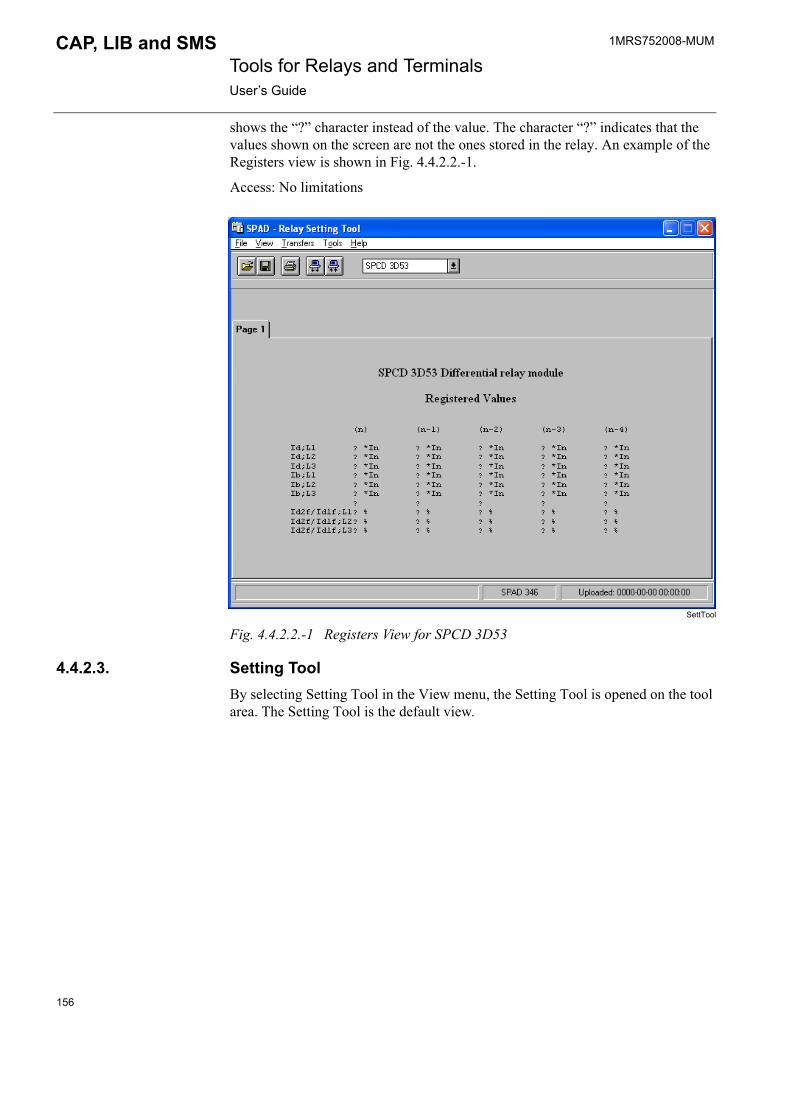
1MRS752008-MUM Tools for Relays and TerminalsUser�s Guide
CAP, LIB and SMS
shows the �?� character instead of the value. The character �?� indicates that the values shown on the screen are not the ones stored in the relay. An example of the Registers view is shown in Fig. 4.4.2.2.-1.
Access: No limitations
SettTool
Fig. 4.4.2.2.-1 Registers View for SPCD 3D53
4.4.2.3. Setting ToolBy selecting Setting Tool in the View menu, the Setting Tool is opened on the tool area. The Setting Tool is the default view.
156

1MRS752008-MUM CAP, LIB and SMS Tools for Relays and TerminalsUser�s Guide
Setting Tool view
MainSett
Fig. 4.4.2.3.-1 Setting Tool view
The Setting Tool view consists of the following parts (see Fig. 4.4.2.3.-1):
1 Parameter group selection Each module contains a number of parameter groups. In the Setting Tool, a list of the function groups available for the relay module can be seen in the parameter group selection.
2 Settings notebook After selecting the parameter group, the parameters of the selected parameter group are displayed in a settings notebook. The number of pages depends on which group is selected in the group selection box. If a new group is selected, the Setting Tool notebook is updated.
3 Present values field The values that are currently used are shown in the relay Present values field. If the parameter values from the default file have been used or the values have been imported, the tool displays the �?� character instead of the present values to indicate that the values shown on the screen are not the ones stored in the relay.
4 New values field The values given by the user are shown in the New values field. When you click the values displayed in this field, the input dialog opens, where you can give the new values.
157
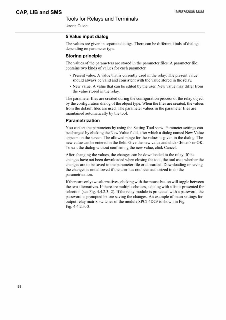
1MRS752008-MUM Tools for Relays and TerminalsUser�s Guide
CAP, LIB and SMS
5 Value input dialog The values are given in separate dialogs. There can be different kinds of dialogs depending on parameter type.
Storing principleThe values of the parameters are stored in the parameter files. A parameter file contains two kinds of values for each parameter:
� Present value. A value that is currently used in the relay. The present value should always be valid and consistent with the value stored in the relay.
� New value. A value that can be edited by the user. New value may differ from the value stored in the relay.
The parameter files are created during the configuration process of the relay object by the configuration dialog of the object type. When the files are created, the values from the default files are used. The parameter values in the parameter files are maintained automatically by the tool.
ParametrizationYou can set the parameters by using the Setting Tool view. Parameter settings can be changed by clicking the New Value field, after which a dialog named New Value appears on the screen. The allowed range for the values is given in the dialog. The new value can be entered in the field. Give the new value and click <Enter> or OK. To exit the dialog without confirming the new value, click Cancel.
After changing the values, the changes can be downloaded to the relay. If the changes have not been downloaded when closing the tool, the tool asks whether the changes are to be saved to the parameter file or discarded. Downloading or saving the changes is not allowed if the user has not been authorized to do the parametrization.
If there are only two alternatives, clicking with the mouse button will toggle between the two alternatives. If there are multiple choices, a dialog with a list is presented for selection (see Fig. 4.4.2.3.-2). If the relay module is protected with a password, the password is prompted before saving the changes. An example of main settings for output relay matrix switches of the module SPCJ 4D29 is shown in Fig. Fig. 4.4.2.3.-3.
158
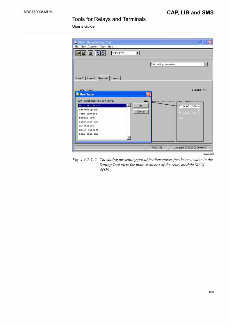
1MRS752008-MUM CAP, LIB and SMS Tools for Relays and TerminalsUser�s Guide
ParamSett
Fig. 4.4.2.3.-2 The dialog presenting possible alternatives for the new value in the Setting Tool view for main switches of the relay module SPCJ 4D29.
159

1MRS752008-MUM Tools for Relays and TerminalsUser�s Guide
CAP, LIB and SMS
MatrixSw
Fig. 4.4.2.3.-3 The main settings for output relay matrix switches of the module SPCJ 4D29.
4.4.3. Transfers menuThe Transfers menu contains commands used to communicate with the relay module.
Fig. 4.4.3.-1 Transfers menu
160
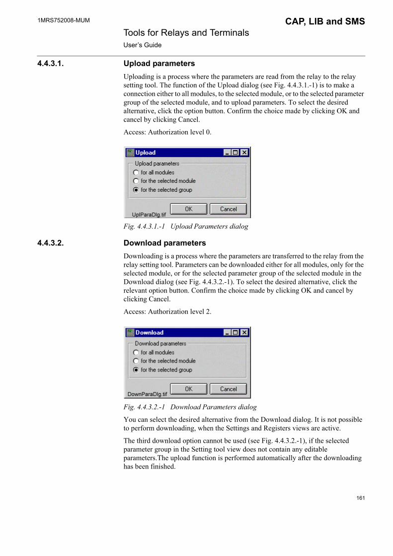
1MRS752008-MUM CAP, LIB and SMS Tools for Relays and TerminalsUser�s Guide
4.4.3.1. Upload parametersUploading is a process where the parameters are read from the relay to the relay setting tool. The function of the Upload dialog (see Fig. 4.4.3.1.-1) is to make a connection either to all modules, to the selected module, or to the selected parameter group of the selected module, and to upload parameters. To select the desired alternative, click the option button. Confirm the choice made by clicking OK and cancel by clicking Cancel.
Access: Authorization level 0.
Fig. 4.4.3.1.-1 Upload Parameters dialog
4.4.3.2. Download parametersDownloading is a process where the parameters are transferred to the relay from the relay setting tool. Parameters can be downloaded either for all modules, only for the selected module, or for the selected parameter group of the selected module in the Download dialog (see Fig. 4.4.3.2.-1). To select the desired alternative, click the relevant option button. Confirm the choice made by clicking OK and cancel by clicking Cancel.
Access: Authorization level 2.
Fig. 4.4.3.2.-1 Download Parameters dialog
You can select the desired alternative from the Download dialog. It is not possible to perform downloading, when the Settings and Registers views are active.
The third download option cannot be used (see Fig. 4.4.3.2.-1), if the selected parameter group in the Setting tool view does not contain any editable parameters.The upload function is performed automatically after the downloading has been finished.
161
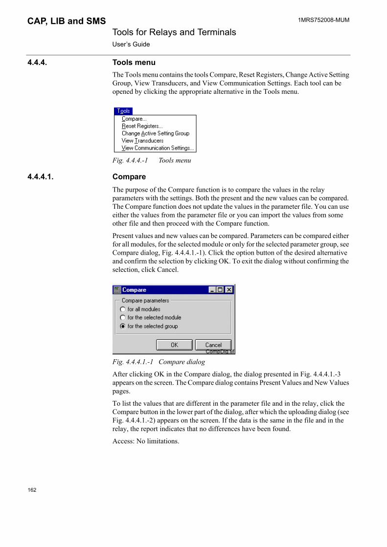
1MRS752008-MUM Tools for Relays and TerminalsUser�s Guide
CAP, LIB and SMS
4.4.4. Tools menuThe Tools menu contains the tools Compare, Reset Registers, Change Active Setting Group, View Transducers, and View Communication Settings. Each tool can be opened by clicking the appropriate alternative in the Tools menu.
Fig. 4.4.4.-1 Tools menu
4.4.4.1. CompareThe purpose of the Compare function is to compare the values in the relay parameters with the settings. Both the present and the new values can be compared. The Compare function does not update the values in the parameter file. You can use either the values from the parameter file or you can import the values from some other file and then proceed with the Compare function.
Present values and new values can be compared. Parameters can be compared either for all modules, for the selected module or only for the selected parameter group, see Compare dialog, Fig. 4.4.4.1.-1). Click the option button of the desired alternative and confirm the selection by clicking OK. To exit the dialog without confirming the selection, click Cancel.
Fig. 4.4.4.1.-1 Compare dialog
After clicking OK in the Compare dialog, the dialog presented in Fig. 4.4.4.1.-3 appears on the screen. The Compare dialog contains Present Values and New Values pages.
To list the values that are different in the parameter file and in the relay, click the Compare button in the lower part of the dialog, after which the uploading dialog (see Fig. 4.4.4.1.-2) appears on the screen. If the data is the same in the file and in the relay, the report indicates that no differences have been found.
Access: No limitations.
162
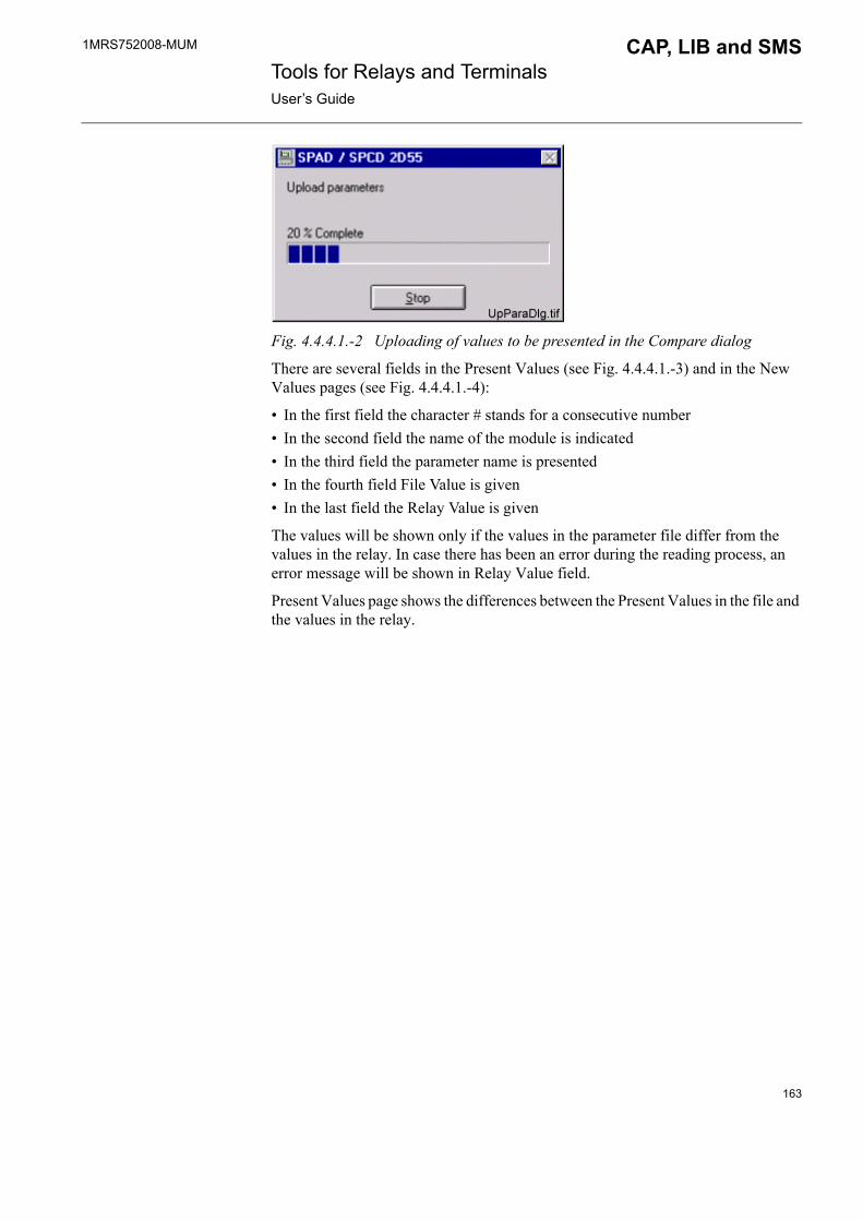
1MRS752008-MUM CAP, LIB and SMS Tools for Relays and TerminalsUser�s Guide
Fig. 4.4.4.1.-2 Uploading of values to be presented in the Compare dialog
There are several fields in the Present Values (see Fig. 4.4.4.1.-3) and in the New Values pages (see Fig. 4.4.4.1.-4):
� In the first field the character # stands for a consecutive number � In the second field the name of the module is indicated� In the third field the parameter name is presented � In the fourth field File Value is given � In the last field the Relay Value is given
The values will be shown only if the values in the parameter file differ from the values in the relay. In case there has been an error during the reading process, an error message will be shown in Relay Value field.
Present Values page shows the differences between the Present Values in the file and the values in the relay.
163
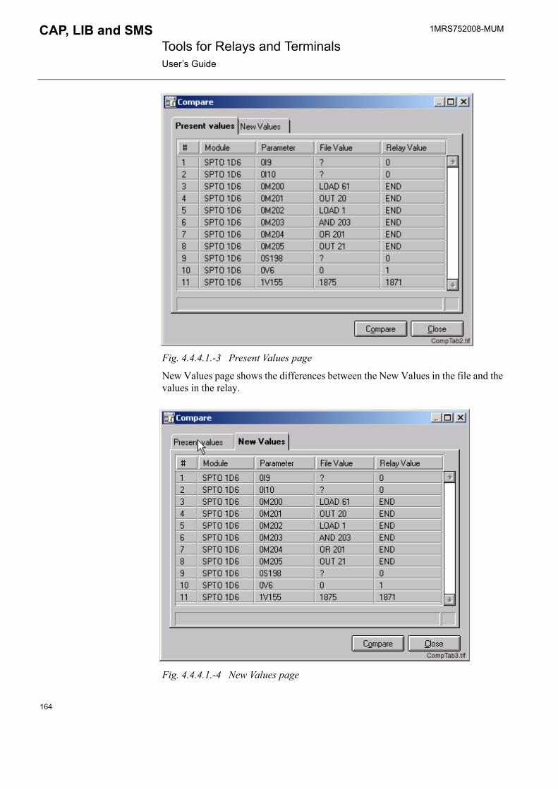
1MRS752008-MUM Tools for Relays and TerminalsUser�s Guide
CAP, LIB and SMS
Fig. 4.4.4.1.-3 Present Values page
New Values page shows the differences between the New Values in the file and the values in the relay.
Fig. 4.4.4.1.-4 New Values page
164
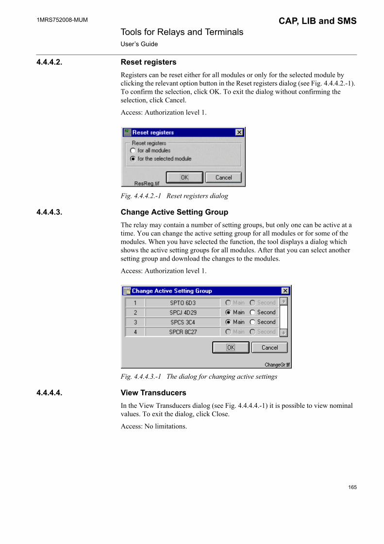
1MRS752008-MUM CAP, LIB and SMS Tools for Relays and TerminalsUser�s Guide
4.4.4.2. Reset registersRegisters can be reset either for all modules or only for the selected module by clicking the relevant option button in the Reset registers dialog (see Fig. 4.4.4.2.-1). To confirm the selection, click OK. To exit the dialog without confirming the selection, click Cancel.
Access: Authorization level 1.
Fig. 4.4.4.2.-1 Reset registers dialog
4.4.4.3. Change Active Setting GroupThe relay may contain a number of setting groups, but only one can be active at a time. You can change the active setting group for all modules or for some of the modules. When you have selected the function, the tool displays a dialog which shows the active setting groups for all modules. After that you can select another setting group and download the changes to the modules.
Access: Authorization level 1.
Fig. 4.4.4.3.-1 The dialog for changing active settings
4.4.4.4. View TransducersIn the View Transducers dialog (see Fig. 4.4.4.4.-1) it is possible to view nominal values. To exit the dialog, click Close.
Access: No limitations.
165

1MRS752008-MUM Tools for Relays and TerminalsUser�s Guide
CAP, LIB and SMS
Fig. 4.4.4.4.-1 View Transducers dialog
4.4.4.5. View Communication SettingsView Communication Setting displays the communication settings for all the modules (see Fig. 4.4.4.5.-1).
Access: No limitations.
Fig. 4.4.4.5.-1 Communication Settings list
4.4.5. Help menuThe Help menu contains only the About Relay Setting Tool dialog.
Fig. 4.4.5.-1 Help menu
4.4.5.1. About Setting ToolThe dialog About Relay Setting Tool contains information about the current version of the Relay Setting Tool.
166
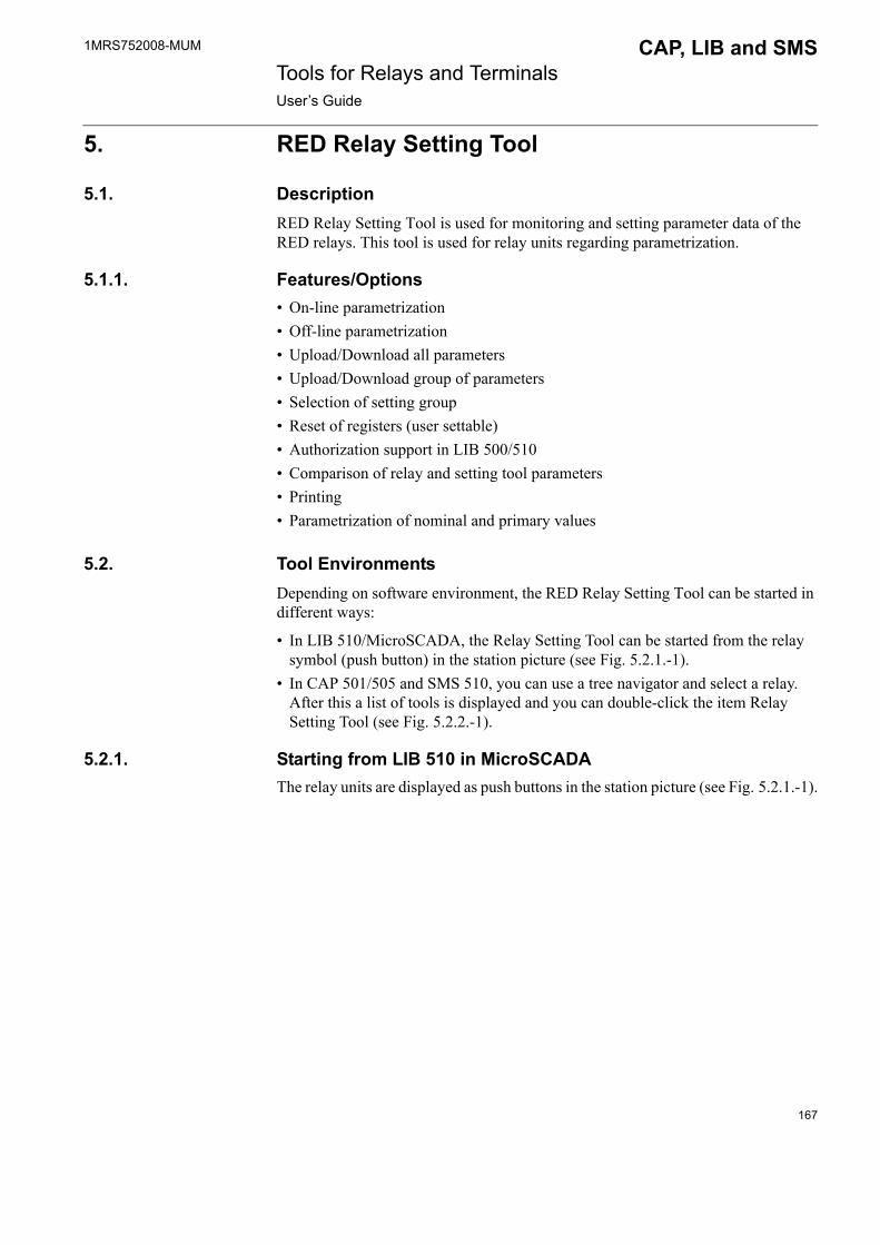
1MRS752008-MUM CAP, LIB and SMS Tools for Relays and TerminalsUser�s Guide
5. RED Relay Setting Tool
5.1. DescriptionRED Relay Setting Tool is used for monitoring and setting parameter data of the RED relays. This tool is used for relay units regarding parametrization.
5.1.1. Features/Options� On-line parametrization� Off-line parametrization� Upload/Download all parameters� Upload/Download group of parameters� Selection of setting group� Reset of registers (user settable)� Authorization support in LIB 500/510� Comparison of relay and setting tool parameters� Printing� Parametrization of nominal and primary values
5.2. Tool EnvironmentsDepending on software environment, the RED Relay Setting Tool can be started in different ways:
� In LIB 510/MicroSCADA, the Relay Setting Tool can be started from the relay symbol (push button) in the station picture (see Fig. 5.2.1.-1).
� In CAP 501/505 and SMS 510, you can use a tree navigator and select a relay. After this a list of tools is displayed and you can double-click the item Relay Setting Tool (see Fig. 5.2.2.-1).
5.2.1. Starting from LIB 510 in MicroSCADAThe relay units are displayed as push buttons in the station picture (see Fig. 5.2.1.-1).
167

1MRS752008-MUM Tools for Relays and TerminalsUser�s Guide
CAP, LIB and SMS
Station
Fig. 5.2.1.-1 The station picture including a relay unit push button
In case objects need updating, a dialog appears when you press the relay unit�s push button (as presented in Fig. 5.2.1.-2). You can update objects either manually in the Picture Editor or automatically by selecting Yes in the new dialog that will appear on the screen. In case you update objects manually in the Picture Editor, the whole configuration procedure has to be updated. In case you select the automatic updating, a dialog confirming that updating was successful appears on the screen (see Fig. 5.2.1.-3).
Fig. 5.2.1.-2 Dialog indicating that an object needs updating
168
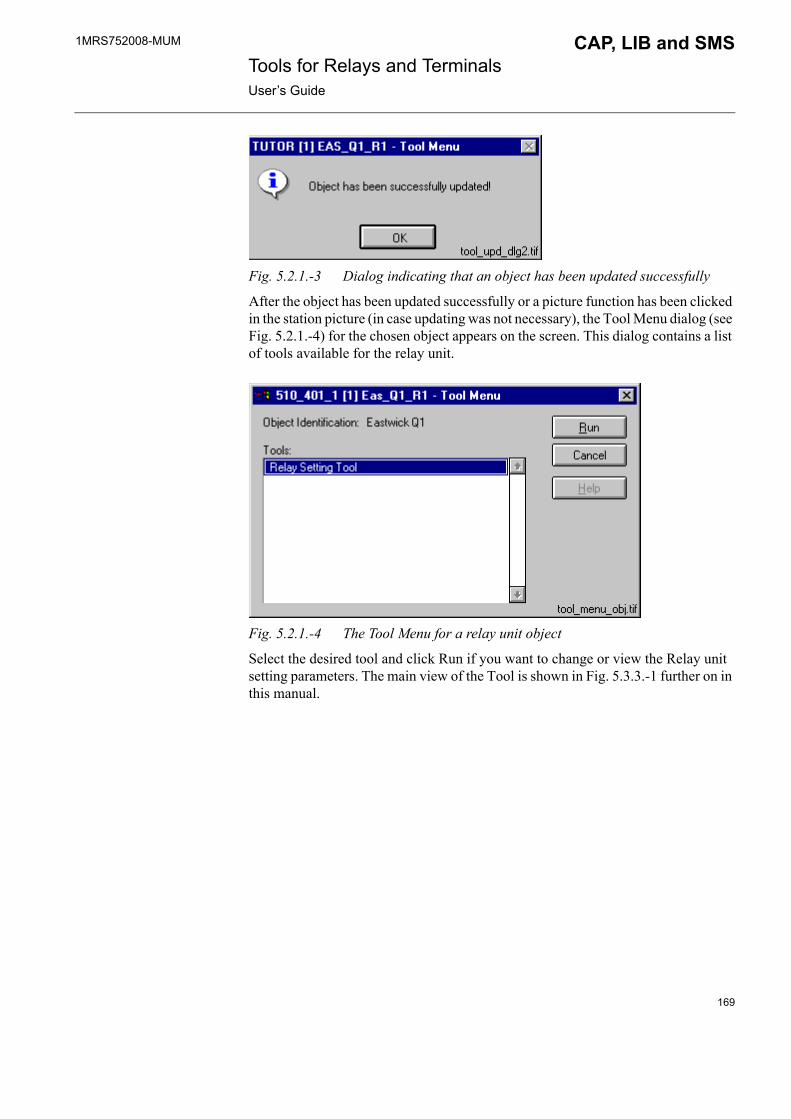
1MRS752008-MUM CAP, LIB and SMS Tools for Relays and TerminalsUser�s Guide
Fig. 5.2.1.-3 Dialog indicating that an object has been updated successfully
After the object has been updated successfully or a picture function has been clicked in the station picture (in case updating was not necessary), the Tool Menu dialog (see Fig. 5.2.1.-4) for the chosen object appears on the screen. This dialog contains a list of tools available for the relay unit.
Fig. 5.2.1.-4 The Tool Menu for a relay unit object
Select the desired tool and click Run if you want to change or view the Relay unit setting parameters. The main view of the Tool is shown in Fig. 5.3.3.-1 further on in this manual.
169
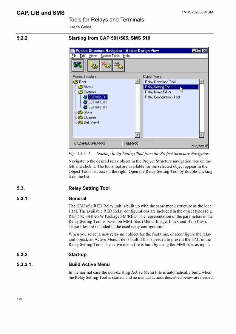
1MRS752008-MUM Tools for Relays and TerminalsUser�s Guide
CAP, LIB and SMS
5.2.2. Starting from CAP 501/505, SMS 510
Fig. 5.2.2.-1 Starting Relay Setting Tool from the Project Structure Navigator
Navigate to the desired relay object in the Project Structure navigation tree on the left and click it. The tools that are available for the selected object appear in the Object Tools list box on the right. Open the Relay Setting Tool by double-clicking it on the list.
5.3. Relay Setting Tool
5.3.1. GeneralThe HMI of a RED Relay unit is built up with the same menu structure as the local HMI. The available RED Relay configurations are included in the object types (e.g. REF 54x) of the SW Package SM/RED. The representation of the parameters in the Relay Setting Tool is based on MMI files (Menu, Image, Index and Help files). These files are included in the used relay configuration.
When you select a new relay unit object for the first time, or reconfigure the relay unit object, an Active Menu File is built. This is needed to present the HMI in the Relay Setting Tool. The active menu file is built by using the MMI files as input.
5.3.2. Start-up
5.3.2.1. Build Active MenuIn the normal case the non-existing Active Menu File is automatically built, when the Relay Setting Tool is started, and no manual actions described below are needed.
170
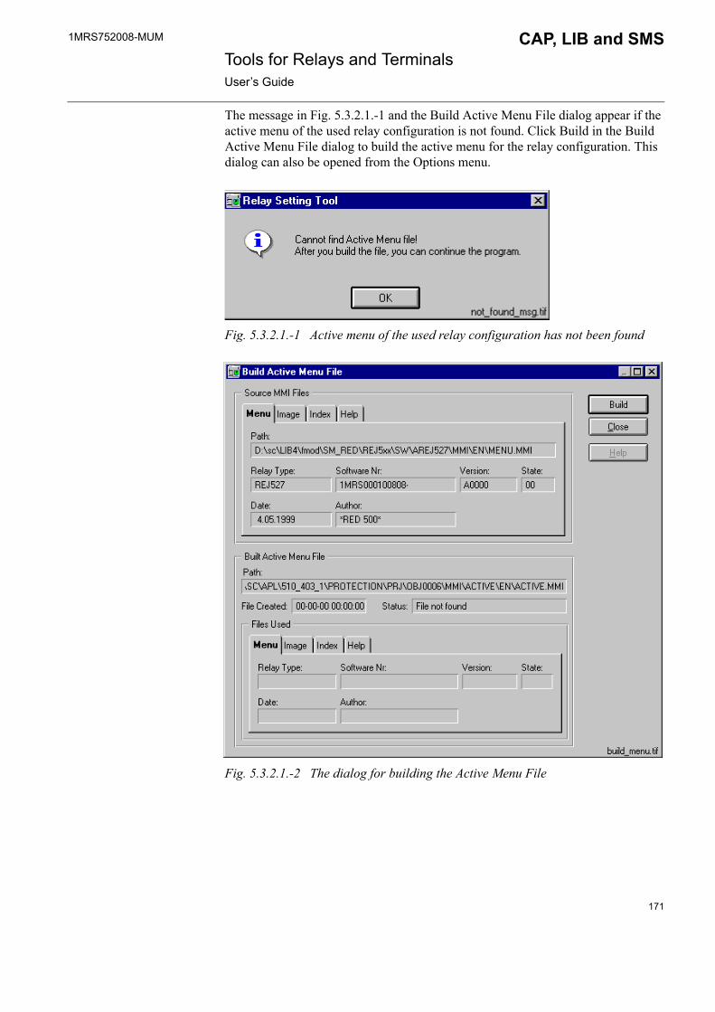
1MRS752008-MUM CAP, LIB and SMS Tools for Relays and TerminalsUser�s Guide
The message in Fig. 5.3.2.1.-1 and the Build Active Menu File dialog appear if the active menu of the used relay configuration is not found. Click Build in the Build Active Menu File dialog to build the active menu for the relay configuration. This dialog can also be opened from the Options menu.
Fig. 5.3.2.1.-1 Active menu of the used relay configuration has not been found
Fig. 5.3.2.1.-2 The dialog for building the Active Menu File
171
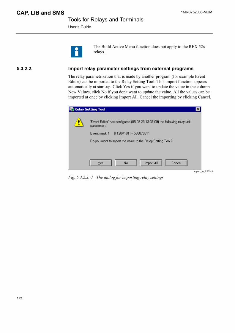
1MRS752008-MUM Tools for Relays and TerminalsUser�s Guide
CAP, LIB and SMS
5.3.2.2. Import relay parameter settings from external programsThe relay parametrization that is made by another program (for example Event Editor) can be imported to the Relay Setting Tool. This import function appears automatically at start-up. Click Yes if you want to update the value in the column New Values, click No if you don't want to update the value. All the values can be imported at once by clicking Import All. Cancel the importing by clicking Cancel.
Import_to_RSTool
Fig. 5.3.2.2.-1 The dialog for importing relay settings
The Build Active Menu function does not apply to the REX 52x relays.
172

1MRS752008-MUM CAP, LIB and SMS Tools for Relays and TerminalsUser�s Guide
5.3.3. Main view
MainView
Fig. 5.3.3.-1 The main view for the Relay Setting Tool
The main view contains the following functions (see Fig. 5.3.3.-1):
1. Menu bar
The menu with commands for the Relay Setting Tool.
2. Toolbar
A bar with buttons that perform some of the most common tasks.
Table 5.3.3-1 The main view toolbar buttons:
Button Functionality
Import parameters
Export parameters
Printing
Upload (receive) parameters
Download (send) parameters
173

1MRS752008-MUM Tools for Relays and TerminalsUser�s Guide
CAP, LIB and SMS
In addition, the toolbar includes the drop-down list for selecting the highest-level node from the parameter tree representation. However, currently there is only one item �MAIN MENU� available for selection,1 i.e. there is no actual use for the drop-down list.
3. Relay unit menu tabbed pages
These pages represent the functions of the selected relay unit. Click the page tab to select the function that you want to operated.
4. Minimize button
The relay tool can be minimized to an icon in the station picture.
5. Tool area
The relay tool is opened into this part of the HSI. The Setting tool function offers a complete tool for monitoring and configuring the relay unit.
6. Status bar
The status bar shows information about the current situation in the Relay Setting Tool. The status bar has three active fields. The first field shows the name of the active view, if there is more than one selectable.The second one shows information of the relay unit type, for example REF 543. The third field shows the upload status of the parameters. The status might be:
� Uploaded 00-00-00 00:00:00, when the parameters of the selected page have been read from the default file.
� Uploaded 00-00-00 00.00.00, when the parameters of the selected page have been uploaded from the relay
status_bar
Fig. 5.3.3.-2 The status bar
5.4. Using Relay Setting Tool
5.4.1. File menuThe file menu contains the functions belonging to file handling.
Fig. 5.4.1.-1 The File menu
1. This implementation is due to the parameter format specification the tool follows.
174

1MRS752008-MUM CAP, LIB and SMS Tools for Relays and TerminalsUser�s Guide
5.4.1.1. ImportingTable 5.4.1.1-1 The Import function:
Fig. 5.4.1.1.-1 The Import dialog for the import function
Access: User level 2.
5.4.1.2. ExportingTable 5.4.1.2-1 The Export function:
Access: User level 2
Selection Functionality
Import Opens a parameter database for importing parameters. The parameter file is selected on the Import dialog (see Fig. 5.4.1.1.-1).
Selection Functionality
Export Saves all parameters for exporting into the file being currently selected. The file name can be selected from the dialog, which is opened first.
175

1MRS752008-MUM Tools for Relays and TerminalsUser�s Guide
CAP, LIB and SMS
Fig. 5.4.1.2.-1 The Export dialog for the export function
Access: User level 2.
5.4.1.3. Page SetupTable 5.4.1.3-1 The Page Setup function:
PageSetDig
Fig. 5.4.1.3.-1 Page Setup dialog
Selection Functionality
Page Setup Opens a dialog in which page setup/margins (Top, Left, Bottom, Right) can be defined.
176

1MRS752008-MUM CAP, LIB and SMS Tools for Relays and TerminalsUser�s Guide
5.4.1.4. Print SetupTable 5.4.1.4-1 The Print Setup function:
Fig. 5.4.1.4.-1 Print Setup dialog
Selection Functionality
Print Setup Opens a dialog in which print setup for the paper as well as for the printer can be defined, if you have selected the option VS Local in the MicroSCADA Monitor.
In case the option VS Remote has been selected in the MicroSCADA Monitor dialog (see Fig. 5.4.1.4.-2), the option Print Setup in the File menu is unavailable, and the dialog presented in Fig. 5.4.1.4.-3 pops up. In this case, information about the printer is given in the MicroSCADA Monitor dialog (the last field on the left-hand side of the dialog in Fig. 5.4.1.4.-2).
177
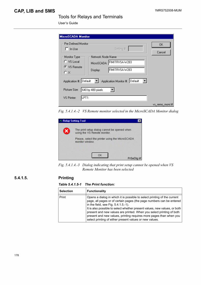
1MRS752008-MUM Tools for Relays and TerminalsUser�s Guide
CAP, LIB and SMS
Fig. 5.4.1.4.-2 VS Remote monitor selected in the MicroSCADA Monitor dialog
Fig. 5.4.1.4.-3 Dialog indicating that print setup cannot be opened when VS Remote Monitor has been selected
5.4.1.5. PrintingTable 5.4.1.5-1 The Print function:
Selection Functionality
Print Opens a dialog in which it is possible to select printing of the current page, all pages or of certain pages (the page numbers can be entered in the field, see Fig. 5.4.1.5.-1).It is also possible to select whether present values, new values, or both present and new values are printed. When you select printing of both present and new values, printing requires more pages than when you select printing of either present values or new values.
178

1MRS752008-MUM CAP, LIB and SMS Tools for Relays and TerminalsUser�s Guide
print_curr_dig
Fig. 5.4.1.5.-1 Print dialog
After you have selected the desired printing option and clicked OK in the Print dialog (see Fig. 5.4.1.5.-1), the second Print dialog (see Fig. 5.4.1.5.-2) pops up. In this dialog you either confirm printing or cancel it.
PrintDlg
Fig. 5.4.1.5.-2 Print dialog 2
Printouts can be made from a Visual SCIL tool, such as the RED Relay Tool, to a local or network printer defined in the operating system. Depending on which context the MicroSCADA monitor is opened in, the available printers and the needed configuration work may differ. This varies in different MicroSCADA technology products, as described in the following sections.
179
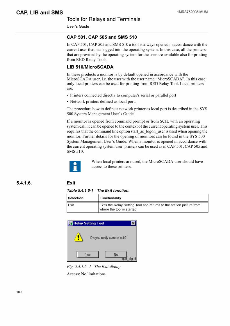
1MRS752008-MUM Tools for Relays and TerminalsUser�s Guide
CAP, LIB and SMS
CAP 501, CAP 505 and SMS 510In CAP 501, CAP 505 and SMS 510 a tool is always opened in accordance with the current user that has logged into the operating system. In this case, all the printers that are provided by the operating system for the user are available also for printing from RED Relay Tools.
LIB 510/MicroSCADAIn these products a monitor is by default opened in accordance with the MicroSCADA user, i.e. the user with the user name �MicroSCADA�. In this case only local printers can be used for printing from RED Relay Tool. Local printers are:� Printers connected directly to computer's serial or parallel port� Network printers defined as local port.
The procedure how to define a network printer as local port is described in the SYS 500 System Management User�s Guide.
If a monitor is opened from command prompt or from SCIL with an operating system call, it can be opened to the context of the current operating system user. This requires that the command line option start_as_logon_user is used when opening the monitor. Further details for the opening of monitors can be found in the SYS 500 System Management User�s Guide. When a monitor is opened in accordance with the current operating system user, printers can be used as in CAP 501, CAP 505 and SMS 510.
5.4.1.6. ExitTable 5.4.1.6-1 The Exit function:
Fig. 5.4.1.6.-1 The Exit dialog
Access: No limitations
When local printers are used, the MicroSCADA user should have access to these printers.
Selection Functionality
Exit Exits the Relay Setting Tool and returns to the station picture from where the tool is started.
180

1MRS752008-MUM CAP, LIB and SMS Tools for Relays and TerminalsUser�s Guide
5.4.2. View menuThe View menu contains a selection of views for the currently selected relay configuration. The All view is always available and it shows all parameters of the active menu. The other possible views are subviews of the All view and they are user-specific. These additional alternatives may be added by using the Options/Menu configuration (described in Section 5.4.5.3.).
Fig. 5.4.2.-1 The View menu
5.4.3. Transfer menuThe Transfer menu contains commands used to communicate with the relay unit. The offered selections below the line in the menu are user-specific. These additional possibilities are to be added by using the Options/Menu configuration (described in Section 5.4.5.3.).
Fig. 5.4.3.-1 The Transfers menu, the Reset selection is shown as an example of an user-specific configuration
Reservation of communicationThe RED Relay Setting Tool reserves communication to the selected object upon a transaction between the tool and the relay unit. Communication is reserved until either the tool is closed or fifteen (15) minutes has elapsed since the transaction ended.
Persistence of write-only parameter settings
It is recommended that whenever a write-only parameter has been activated it should be immediately deactivated once used in a download. By following this practice, write-only parameters are never inadvertently used in future downloads.
All write-only parameters that have been changed and thereafter saved in the parameter file, remain effective until manually reset to their initial ineffective state. For example, if the value of the "Reset registers" command is set to "Reset" in the New Value field and the values are stored when exiting the tool, then the "Reset registers" command is still active the next time the tool is opened. In order to take the "Reset" command out of use, the value in the New Value field must be set to "0" (the original value) and, after that saved in the parameter file.
181

1MRS752008-MUM Tools for Relays and TerminalsUser�s Guide
CAP, LIB and SMS
Distinction between the types ("write-only" or "normal") of individual parameters should be based on the information which is available in the respective relay terminal unit manual. The values of the write-only parameters cannot be read from the relay terminal unit. The Relay Setting Tool does not provide this information.
5.4.3.1. UploadTable 5.4.3.1-1 The Upload function:
upl_curr
Fig. 5.4.3.1.-1 The dialog for selecting the uploading method
Access: User level 0.
5.4.3.2. DownloadBefore the actual download operation can begin, the tool checks the status of the parameter values. If, based on the registered time stamps, some parameter values have never been uploaded from the relay unit, a warning is shown before executing the requested download operation.
download_warning
Fig. 5.4.3.2.-1 Warning dialog for not uploaded parameters
Selection Functionality
Upload Connects to the selected unit and uploads (receives):1) parameters that are defined in the current page2) all parameters of the current view (selected in the View menu)3) parameters on the entered pages.
182

1MRS752008-MUM CAP, LIB and SMS Tools for Relays and TerminalsUser�s Guide
Table 5.4.3.2-1 The Download function:
dowl_curr
Fig. 5.4.3.2.-2 The dialog for selecting the downloading method
Access: User level 2.
After uploading/downloading has been started, the dialog shown in Fig. 5.4.3.2.-3 appears on the screen. The dialog gives you information about the current operation (uploading/downloading). It also shows how downloading proceeds. The Stop button cancels the operation and removes the dialog.
uploading_dlg
Fig. 5.4.3.2.-3 The communication dialog
After the uploading/downloading process is completed, the dialog is closed and the tool area is updated.
If an error occurs during communication (the relay answers with the NAK code), the error dialog is shown with the possibility to either skip, retry or cancel the reading.
If the communication error is such that the relay unit does not answer, a dialog is opened, which prompts you to select whether to Retry or Cancel the downloading process.
Selection Functionality
Download 1) parameters that are defined in the current page2) all parameters of the current view (selected in the View menu)3) parameters on the entered pages.
183
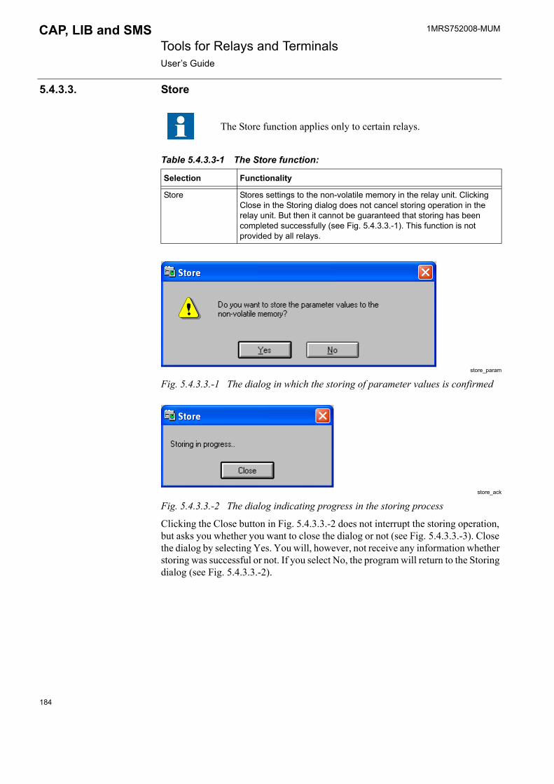
1MRS752008-MUM Tools for Relays and TerminalsUser�s Guide
CAP, LIB and SMS
5.4.3.3. Store
Table 5.4.3.3-1 The Store function:
store_param
Fig. 5.4.3.3.-1 The dialog in which the storing of parameter values is confirmed
store_ack
Fig. 5.4.3.3.-2 The dialog indicating progress in the storing process
Clicking the Close button in Fig. 5.4.3.3.-2 does not interrupt the storing operation, but asks you whether you want to close the dialog or not (see Fig. 5.4.3.3.-3). Close the dialog by selecting Yes. You will, however, not receive any information whether storing was successful or not. If you select No, the program will return to the Storing dialog (see Fig. 5.4.3.3.-2).
The Store function applies only to certain relays.
Selection Functionality
Store Stores settings to the non-volatile memory in the relay unit. Clicking Close in the Storing dialog does not cancel storing operation in the relay unit. But then it cannot be guaranteed that storing has been completed successfully (see Fig. 5.4.3.3.-1). This function is not provided by all relays.
184

1MRS752008-MUM CAP, LIB and SMS Tools for Relays and TerminalsUser�s Guide
close_store
Fig. 5.4.3.3.-3 Dialog asking whether you want to close the storing dialog
StoreSuccess
Fig. 5.4.3.3.-4 Storing completed successfully!
5.4.3.4. Reset (example)Table 5.4.3.4-1 The Reset function:
Fig. 5.4.3.4.-1 The dialog for resetting relay unit
Selection Functionality
Reset Opens a dialog for some general resetting operations. Select the wanted action and click Send. See the example in Fig. 5.4.3.4.-1.
185

1MRS752008-MUM Tools for Relays and TerminalsUser�s Guide
CAP, LIB and SMS
Fig. 5.4.3.4.-2 The dialog in which the selected action can be confirmed
5.4.4. Tools menuThe Tools menu contains miscellaneous tools and commands.
Fig. 5.4.4.-1 Tools menu
5.4.4.1. CompareTable 5.4.4.1-1 The Compare function:
In the Present Values and in the New Values pages (see Fig. 5.4.4.1.-1) there are several fields:
� In the first field the character # stands for a consecutive number � the second field (called Parameter) indicates the description of the parameter� In the third field the database name is presented � In the fourth field the File Value is given � In the last field the Relay Value is given
Selection Functionality
Compare The purpose of this function is to check that the values in the parameter file and in the relay are the same. The Compare dialog contains two pages: � Present Values page shows the differences between the Present
Values in the file and the values in the relay. � New Values page shows the differences between the New Values in
the file and the values in the relay.
186

1MRS752008-MUM CAP, LIB and SMS Tools for Relays and TerminalsUser�s Guide
Fig. 5.4.4.1.-1 Compare dialog in which the comparing process can be started by pressing the Compare button.
The values will be shown only if the values in the parameter file differ from the values in the relay. In case there has been an error during the reading process, an error message will be shown in the Relay Value field. You can start the comparing process by pressing the Compare button in the lower part of the dialog. Click Close to exit the dialog without starting the comparing process.
comp_dlg2
Fig. 5.4.4.1.-2 Compare Uploading dialog
When you click a field in the Present Values or New Values page, the field is activated (shown in blue as presented in Fig. 5.4.4.1.-3). A menu path is shown in the field on the left-hand side of the dialog in the status bar. The time when the File Value was updated last time is shown on the right-hand side in the status bar.
187
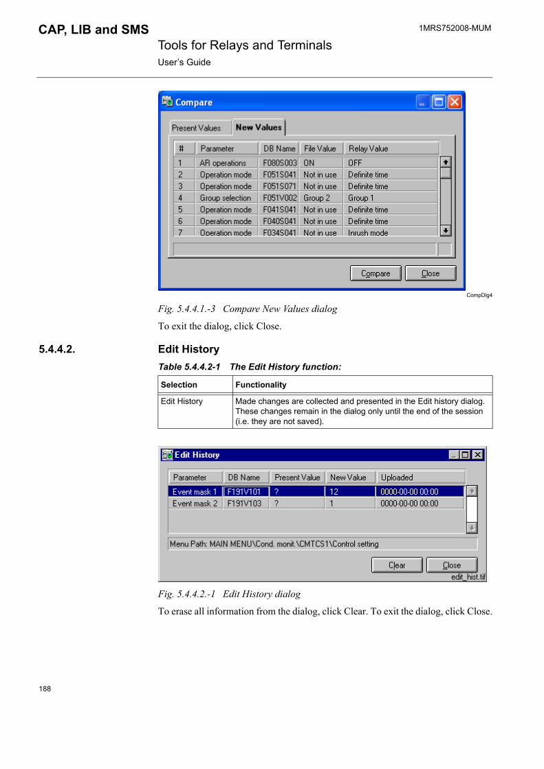
1MRS752008-MUM Tools for Relays and TerminalsUser�s Guide
CAP, LIB and SMS
CompDlg4
Fig. 5.4.4.1.-3 Compare New Values dialog
To exit the dialog, click Close.
5.4.4.2. Edit HistoryTable 5.4.4.2-1 The Edit History function:
Fig. 5.4.4.2.-1 Edit History dialog
To erase all information from the dialog, click Clear. To exit the dialog, click Close.
Selection Functionality
Edit History Made changes are collected and presented in the Edit history dialog. These changes remain in the dialog only until the end of the session (i.e. they are not saved).
188

1MRS752008-MUM CAP, LIB and SMS Tools for Relays and TerminalsUser�s Guide
5.4.4.3. View TransducersTable 5.4.4.3-1 The View Transducers function:
Fig. 5.4.4.3.-1 Transducers dialog
To exit the dialog, click Close.
5.4.5. Options menuThe Options menu contains miscellaneous tools and commands.
Fig. 5.4.5.-1 The Options menu
5.4.5.1. Resize Dialog Table 5.4.5.1-1 The Resize Dialog function:
Access: User level 1.
Selection Functionality
View Transducers Nominal values can be viewed in the View Transducers dialog. These nominal values are used when calculating primary values for certain parameters (see Fig. 5.4.7.2.-1, note 6). Values are defined in the Object Configuration Tool, please see �RED relay object types� on page 17.
Selection Functionality
Resize Dialog Opens a dialog in which the size of the dialog can be changed (see Fig. 5.4.5.1.-1).
189
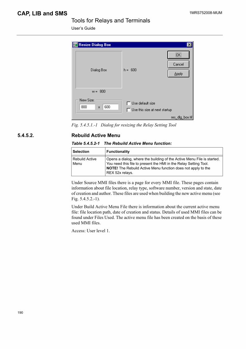
1MRS752008-MUM Tools for Relays and TerminalsUser�s Guide
CAP, LIB and SMS
Fig. 5.4.5.1.-1 Dialog for resizing the Relay Setting Tool
5.4.5.2. Rebuild Active MenuTable 5.4.5.2-1 The Rebuild Active Menu function:
Under Source MMI files there is a page for every MMI file. These pages contain information about file location, relay type, software number, version and state, date of creation and author. These files are used when building the new active menu (see Fig. 5.4.5.2.-1).
Under Build Active Menu File there is information about the current active menu file: file location path, date of creation and status. Details of used MMI files can be found under Files Used. The active menu file has been created on the basis of these used MMI files.
Access: User level 1.
Selection Functionality
Rebuild Active Menu
Opens a dialog, where the building of the Active Menu File is started. You need this file to present the HMI in the Relay Setting Tool. NOTE! The Rebuild Active Menu function does not apply to theREX 52x relays.
190
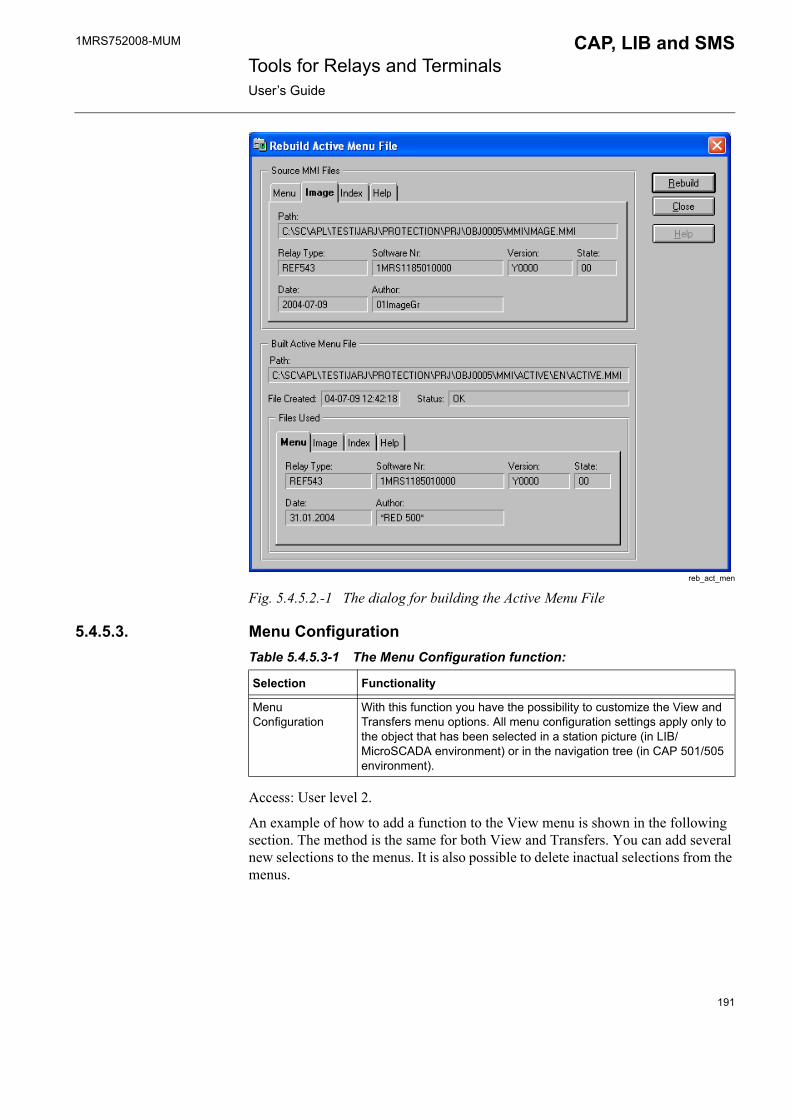
1MRS752008-MUM CAP, LIB and SMS Tools for Relays and TerminalsUser�s Guide
reb_act_men
Fig. 5.4.5.2.-1 The dialog for building the Active Menu File
5.4.5.3. Menu ConfigurationTable 5.4.5.3-1 The Menu Configuration function:
Access: User level 2.
An example of how to add a function to the View menu is shown in the following section. The method is the same for both View and Transfers. You can add several new selections to the menus. It is also possible to delete inactual selections from the menus.
Selection Functionality
Menu Configuration
With this function you have the possibility to customize the View and Transfers menu options. All menu configuration settings apply only to the object that has been selected in a station picture (in LIB/MicroSCADA environment) or in the navigation tree (in CAP 501/505 environment).
191
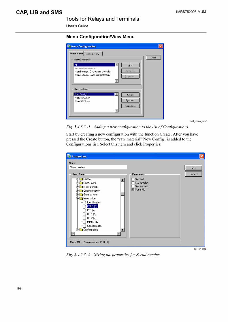
1MRS752008-MUM Tools for Relays and TerminalsUser�s Guide
CAP, LIB and SMS
Menu Configuration/View Menu
add_menu_conf
Fig. 5.4.5.3.-1 Adding a new configuration to the list of Configurations
Start by creating a new configuration with the function Create. After you have pressed the Create button, the �raw material� New Config1 is added to the Configurations list. Select this item and click Properties.
ser_nr_prop
Fig. 5.4.5.3.-2 Giving the properties for Serial number
192
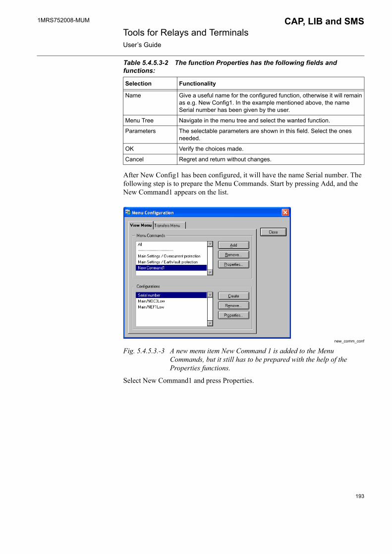
1MRS752008-MUM CAP, LIB and SMS Tools for Relays and TerminalsUser�s Guide
Table 5.4.5.3-2 The function Properties has the following fields and functions:
After New Config1 has been configured, it will have the name Serial number. The following step is to prepare the Menu Commands. Start by pressing Add, and the New Command1 appears on the list.
new_comm_conf
Fig. 5.4.5.3.-3 A new menu item New Command 1 is added to the Menu Commands, but it still has to be prepared with the help of the Properties functions.
Select New Command1 and press Properties.
Selection Functionality
Name Give a useful name for the configured function, otherwise it will remain as e.g. New Config1. In the example mentioned above, the name Serial number has been given by the user.
Menu Tree Navigate in the menu tree and select the wanted function.
Parameters The selectable parameters are shown in this field. Select the ones needed.
OK Verify the choices made.
Cancel Regret and return without changes.
193

1MRS752008-MUM Tools for Relays and TerminalsUser�s Guide
CAP, LIB and SMS
Fig. 5.4.5.3.-4 Giving the name for the menu function and binding it to the appropriate configuration.
Table 5.4.5.3-3 Menu Properties contains the following fields and functions:
The new menu selection is at your disposal after closing the Options/Menu configuration function.
Fig. 5.4.5.3.-5 The new menu selection is at your disposal
Menu Configuration/Transfers MenuYou have the possibility of preparing your own Transfers menu. The method is exactly the same as described in the previous section regarding the View menu, see Section 5.4.5.3.
Selection Functionality
View name Rename the New Command1 with the name you intend to present in the View menu.
Bind to Configurations
You will now have to bind a configuration with the menu selection.
OK Verify your changes/setup
Cancel Regret and leave without changes
194
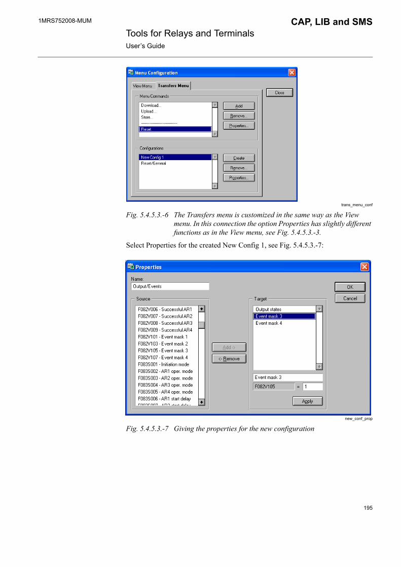
1MRS752008-MUM CAP, LIB and SMS Tools for Relays and TerminalsUser�s Guide
trans_menu_conf
Fig. 5.4.5.3.-6 The Transfers menu is customized in the same way as the View menu. In this connection the option Properties has slightly different functions as in the View menu, see Fig. 5.4.5.3.-3.
Select Properties for the created New Config 1, see Fig. 5.4.5.3.-7:
new_conf_prop
Fig. 5.4.5.3.-7 Giving the properties for the new configuration
195

1MRS752008-MUM Tools for Relays and TerminalsUser�s Guide
CAP, LIB and SMS
Table 5.4.5.3-4 Properties dialog contains the following fields and functions:
Remarks regarding Fig. 5.4.5.3.-7:
As it can be seen in the Source list in Fig. 5.4.5.3.-7, a huge amount of parameters/items can be selected and added to the Target list. Normally, the idea is not to make parametrization of the relay parameters via the Transfers menu even if it is possible, but to enable e.g. resetting of registers, indications etc. in the relay. Relay parametrization and monitoring is described further on in Section 5.4.7.
Furthermore, the user should check that the value of each parameter/item in the Target list has the right value (in the field on the right side of the parameter code). In other words, you should ensure that the parameter/item has the value you want to send to the relay. The default value is not always the wanted one. The values can, of course, be changed afterwards, whenever necessary. It is also recommended to take into consideration that giving �wrong� value may result in that the expected result remains unfulfilled when executing the menu selection in the Transfers menu.
5.4.6. HelpThe Help menu contains an on-line help for the tool functions.
Fig. 5.4.6.-1 The Help menu
Selection Functionality
Name Give a useful name for your configured function, otherwise it will remain as e.g. New Config 1. In the example above the name Outputs/Events is given by the user.
Source Select the wanted parameters or items to be added to the Target and click the Add button
Target The Target list contains a list of all added items from the Source list. By selecting the items one by one, the text can be edited. The field for the parameter code, e.g. F127V107 cannot be edited, but the value in the field to the right can be changed. Click Apply to verify each change of an item on the Target list.
Add Adds the selected item from the Source list to the Target list
Remove Removes the selected item from the Target list
OK Verify your selections and modifications made
Cancel Regret and return without changes, also those confirmed with the Apply button
196

1MRS752008-MUM CAP, LIB and SMS Tools for Relays and TerminalsUser�s Guide
5.4.6.1. About Relay Setting ToolTable 5.4.6.1-1 About Setting Tool:
Access: No limitations.
5.4.7. Monitoring and changing parametersThe RED Relay Setting Tool gives you a powerful tool for monitoring and configuring the relay units.
5.4.7.1. RED menusWhen a menu from the Relay Setting Tool is selected, a menu hierarchy of the functions (see Fig. 5.4.7.2.-1, item 1) available for the relay unit is displayed in the tool area. Each function holds several tabbed pages of configurable parameters.
5.4.7.2. Tabbed pagesThe Relay Setting Tool�s Main View contains tabbed pages. The hierarchy and the number of these tabbed pages depends on the selected relay. A tabbed page can be selected by clicking the wanted page with the mouse, e.g. page 68 (see item 2 in Fig. 5.4.7.2.-1). Item 3 in Fig. 5.4.7.2.-1 indicates the last page (313).
RelMainView
Fig. 5.4.7.2.-1 Relay Setting Tool�s Main View
Selection Functionality
About Setting Tool Gives information regarding the setting tool.
197

1MRS752008-MUM Tools for Relays and TerminalsUser�s Guide
CAP, LIB and SMS
5.4.7.3. ParametrizationThe Setting Tool pictures hold a field indicating the Present Value and a field indicating the New Value. After you have changed the new values, the changes have to be downloaded to the relay unit. To download parameters, select Transfers menu and click Download parameters. The Present Value field is updated when you have downloaded the new values.
If there are multiple choices, the suitable alternative can be selected from the drop-down combo box (see item 4 in Fig. 5.4.7.2.-1). If the relay unit is protected by a password, the password is prompted before you can download the changes. To enter a new value, press the mouse button or any key in the New Value field (item 5 in Fig. 5.4.7.2.-1). A dialog opens in which you can enter the new value (see Fig. 5.4.7.3.-1). Item 6 is also an input field for the new value. Whether this is in use or not, is defined in the Object Configuration Tool.
Fig. 5.4.7.3.-1 The input field of the Setting Tool
198
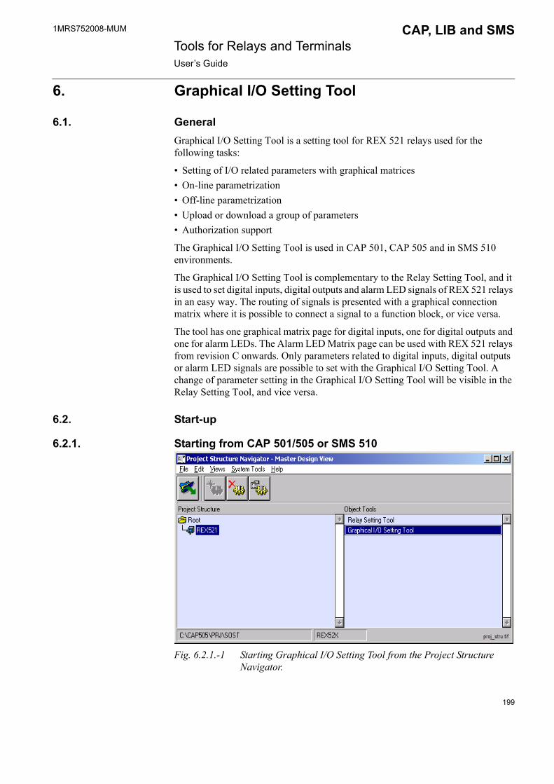
1MRS752008-MUM CAP, LIB and SMS Tools for Relays and TerminalsUser�s Guide
6. Graphical I/O Setting Tool
6.1. GeneralGraphical I/O Setting Tool is a setting tool for REX 521 relays used for the following tasks:
� Setting of I/O related parameters with graphical matrices� On-line parametrization� Off-line parametrization� Upload or download a group of parameters� Authorization support
The Graphical I/O Setting Tool is used in CAP 501, CAP 505 and in SMS 510 environments.
The Graphical I/O Setting Tool is complementary to the Relay Setting Tool, and it is used to set digital inputs, digital outputs and alarm LED signals of REX 521 relays in an easy way. The routing of signals is presented with a graphical connection matrix where it is possible to connect a signal to a function block, or vice versa.
The tool has one graphical matrix page for digital inputs, one for digital outputs and one for alarm LEDs. The Alarm LED Matrix page can be used with REX 521 relays from revision C onwards. Only parameters related to digital inputs, digital outputs or alarm LED signals are possible to set with the Graphical I/O Setting Tool. A change of parameter setting in the Graphical I/O Setting Tool will be visible in the Relay Setting Tool, and vice versa.
6.2. Start-up
6.2.1. Starting from CAP 501/505 or SMS 510
Fig. 6.2.1.-1 Starting Graphical I/O Setting Tool from the Project Structure Navigator.
199

1MRS752008-MUM Tools for Relays and TerminalsUser�s Guide
CAP, LIB and SMS
Navigate to the desired relay object in the Project Structure navigation tree on the left and select it. The tools that are available for the selected object appear on theObject Tools list on the right. Open the Graphical I/O Setting Tool by double-clicking it on the list.
6.3. Main view
Fig. 6.3.-1 The main view
The main view includes the following functions:
1. Menu bar
The menu with commands for the Graphical I/O Setting Tool.
2. Toolbar
The toolbar contains buttons that perform the most common tasks.
Table 6.3.-1 Main view toolbar buttons:
Button Functionality
Import parameters
Export parameters
200
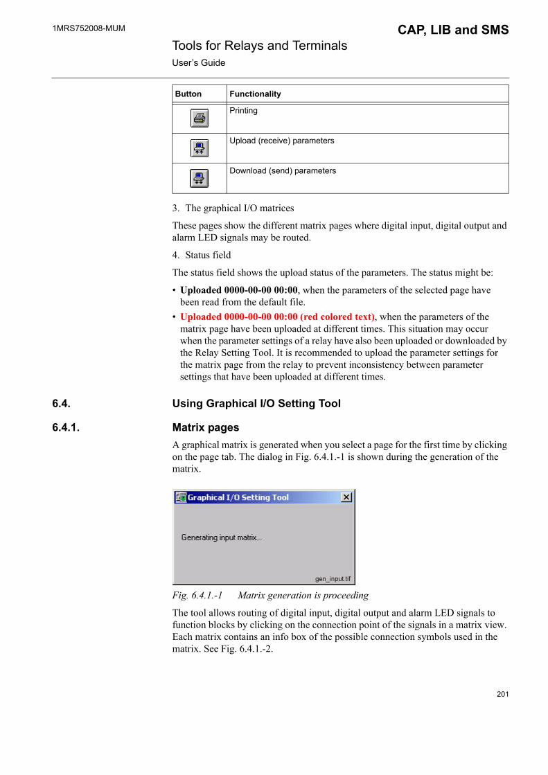
1MRS752008-MUM CAP, LIB and SMS Tools for Relays and TerminalsUser�s Guide
3. The graphical I/O matrices
These pages show the different matrix pages where digital input, digital output and alarm LED signals may be routed.
4. Status field
The status field shows the upload status of the parameters. The status might be:
� Uploaded 0000-00-00 00:00, when the parameters of the selected page have been read from the default file.
� Uploaded 0000-00-00 00:00 (red colored text), when the parameters of the matrix page have been uploaded at different times. This situation may occur when the parameter settings of a relay have also been uploaded or downloaded by the Relay Setting Tool. It is recommended to upload the parameter settings for the matrix page from the relay to prevent inconsistency between parameter settings that have been uploaded at different times.
6.4. Using Graphical I/O Setting Tool
6.4.1. Matrix pagesA graphical matrix is generated when you select a page for the first time by clicking on the page tab. The dialog in Fig. 6.4.1.-1 is shown during the generation of the matrix.
Fig. 6.4.1.-1 Matrix generation is proceeding
The tool allows routing of digital input, digital output and alarm LED signals to function blocks by clicking on the connection point of the signals in a matrix view. Each matrix contains an info box of the possible connection symbols used in the matrix. See Fig. 6.4.1.-2.
Printing
Upload (receive) parameters
Download (send) parameters
Button Functionality
201

1MRS752008-MUM Tools for Relays and TerminalsUser�s Guide
CAP, LIB and SMS
Fig. 6.4.1.-2 Possible connection symbols for the Input Matrix
The connection symbol �Connection not possible� is shown for a half second when you try to make a connection that is not possible.
This situation occurs when some other signals already are connected to each other and the selected signal cannot be connected due to the parameter types and the settings of the parameters.
Fig. 6.4.1.-3 shows an example where it is not possible to connect the digital input signal DI9 to the Blocking 1 switchgroup, because the digital input DI1 is already connected to the Blocking 1 switchgroup.
Fig. 6.4.1.-3 An Input Matrix in which a connection of DI9 input to Blocking 1 switchgroup is impossible.
The connections between the digital input DI1 and the Blocking 1 switchgroup (see Fig. 6.4.1.-3) must first be disconnected by clicking on the connected connections. After this, it is possible to connect the selected digital input DI9 to the Blocking 1 signal.
Signals can basically be routed in the same way in the three matrices, but there are some differences because of the standard configuration and parameter types used in the relay. The routing of signals is described in detail in Sections 6.4.1.1- 6.4.1.3.
202
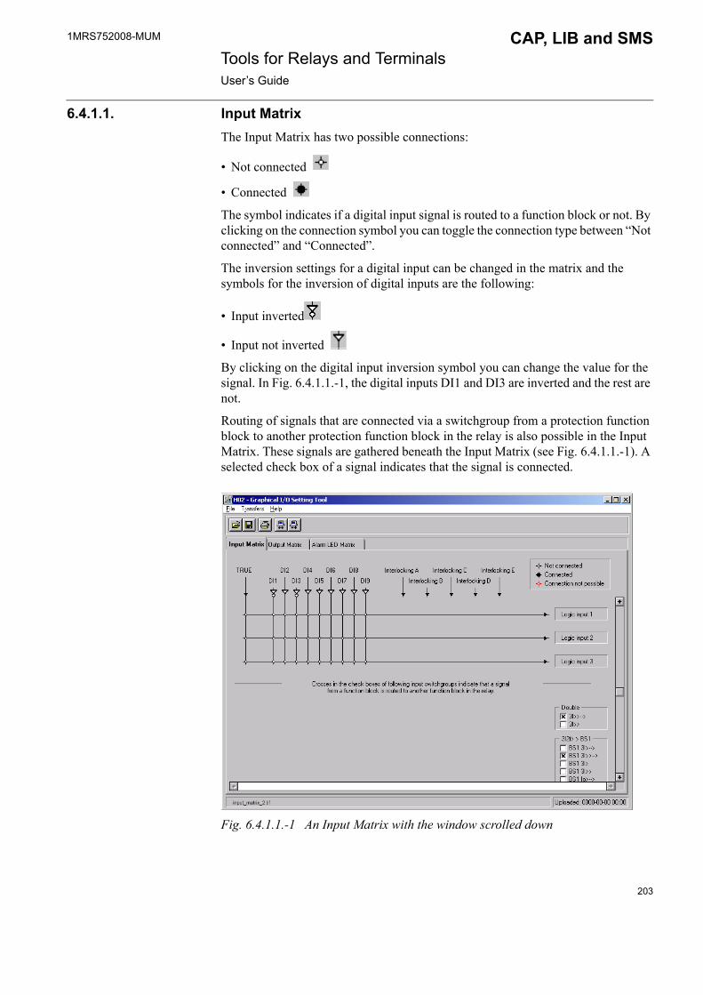
1MRS752008-MUM CAP, LIB and SMS Tools for Relays and TerminalsUser�s Guide
6.4.1.1. Input MatrixThe Input Matrix has two possible connections:
� Not connected
� Connected
The symbol indicates if a digital input signal is routed to a function block or not. By clicking on the connection symbol you can toggle the connection type between �Not connected� and �Connected�.
The inversion settings for a digital input can be changed in the matrix and the symbols for the inversion of digital inputs are the following:
� Input inverted
� Input not inverted
By clicking on the digital input inversion symbol you can change the value for the signal. In Fig. 6.4.1.1.-1, the digital inputs DI1 and DI3 are inverted and the rest are not.
Routing of signals that are connected via a switchgroup from a protection function block to another protection function block in the relay is also possible in the Input Matrix. These signals are gathered beneath the Input Matrix (see Fig. 6.4.1.1.-1). A selected check box of a signal indicates that the signal is connected.
Fig. 6.4.1.1.-1 An Input Matrix with the window scrolled down
203

1MRS752008-MUM Tools for Relays and TerminalsUser�s Guide
CAP, LIB and SMS
6.4.1.2. Output MatrixThe Output Matrix has three possible connections:
� Not connected
� Connected and non-latched
� Connected and latched
The symbols indicate the way a signal is connected from a function block to a digital output relay. Note that the �Connected and latched� connection is only possible for the trip signals (Trip 1, Trip 2 and Trip 3). The value of the connection changes in the following order when it is selected: �Not connected�, �Connected and non-latched�, �Connected and latched�, �Not connected�, and so on.
Fig. 6.4.1.2.-1 shows an example of the Output Matrix.
Fig. 6.4.1.2.-1 An Output Matrix
The routing of one signal or the change of a connection value in the Output Matrix may affect other connections at the same time. Following examples describe a situation where this may occur:
Example 1
If you want to change the connection type between Trip 1, 3I> and HSPO1 to �Connected and latched� by clicking on the connection (see Fig. 6.4.1.2.-1), other connections might be affected. In this case, the connections between Trip 2, 3I> and SO1, SO2 will also become �Connected and latched� as shown in the next picture (see Fig. 6.4.1.2.-2). This behaviour originates from the standard configuration, in which the 3I> (Trip 1, Trip 2 and Trip 3) signals are connected to the same protection
204

1MRS752008-MUM CAP, LIB and SMS Tools for Relays and TerminalsUser�s Guide
function block output. Changing the value of a trip signal parameter, which sets the non-latching or latching state of the trip signal for the protection function block, will affect all connected trip signals.
Fig. 6.4.1.2.-2 An Output Matrix showing �Connected and latched� connections
Example 2
If we want to route the Trip 2, 3I>> signal to PO1 by clicking on the connection (see Fig. 6.4.1.2.-2), other related connections could be affected. In this case the connections between Trip2, 3I>> and SO1, SO2 will become �Connected and non-latched� and the connection between Trip 2, 3I> and PO1 will become �Connected and latched� (see Fig. 6.4.1.2.-3). This behaviour originates from the output switchgroups and output selectors used in the standard configuration for routing of output signals.
205

1MRS752008-MUM Tools for Relays and TerminalsUser�s Guide
CAP, LIB and SMS
Fig. 6.4.1.2.-3 An Output Matrix showing �Connected and non-latched� and �Connected and latched� connections.
6.4.1.3. Alarm LED MatrixThe Alarm LED Matrix has four connection symbols:
� Not connected
� Non-latched alarm
� Latched alarm steady LED
� Latched alarm flashing LED
The symbol indicates if a signal is connected to an alarm LED, and in what way the LED indicates an alarm (see Fig. 6.4.1.3.-1). The value of the connection changes in the following order when it is selected; �Not connected�, �Non-latched alarm�, �Latched alarm steady LED�, �Latched alarm flashing LED�, �Not connected�, and so on.
206
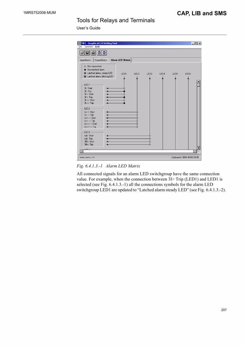
1MRS752008-MUM CAP, LIB and SMS Tools for Relays and TerminalsUser�s Guide
Fig. 6.4.1.3.-1 Alarm LED Matrix
All connected signals for an alarm LED switchgroup have the same connection value. For example, when the connection between 3I> Trip (LED1) and LED1 is selected (see Fig. 6.4.1.3.-1) all the connections symbols for the alarm LED switchgroup LED1 are updated to �Latched alarm steady LED� (see Fig. 6.4.1.3.-2).
207

1MRS752008-MUM Tools for Relays and TerminalsUser�s Guide
CAP, LIB and SMS
Fig. 6.4.1.3.-2 An Alarm LED Matrix showing �Latched alarm steady LED� in switchgroup LED1.
6.4.2. File menuThe file menu contains the functions belonging to file handling. The functions of the file menu are the same as in the RED Relay Setting Tool. Therefore, for details about Import, Export, Page Setup, Print Setup and Exit functions, refer to Section 5.4 in Chapter 5 �RED Relay Setting Tool�. For details about the printing function, see Section 6.4.2.1.
Fig. 6.4.2.-1 File menu
208

1MRS752008-MUM CAP, LIB and SMS Tools for Relays and TerminalsUser�s Guide
6.4.2.1. Printing
After you have selected the printable matrix pages for printing, click OK (see Fig. 6.4.2.1.-1). The second print dialog will be opened (see Fig. 6.4.2.1.-2) in which you can either confirm printing or cancel it.
print_1
Fig. 6.4.2.1.-1 Print dialog
print_2
Fig. 6.4.2.1.-2 Confirm or cancel printing
Table 6.4.2.1-1 The Printing function:
Selection FunctionalityPrint Opens a dialog in which it is possible to select printing of
the current matrix page or all matrix pages. Printed output of the matrix pages is similar to what is displayed on the screen.
209
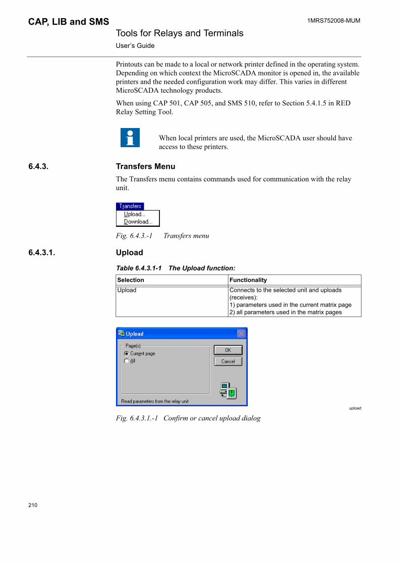
1MRS752008-MUM Tools for Relays and TerminalsUser�s Guide
CAP, LIB and SMS
Printouts can be made to a local or network printer defined in the operating system. Depending on which context the MicroSCADA monitor is opened in, the available printers and the needed configuration work may differ. This varies in different MicroSCADA technology products.
When using CAP 501, CAP 505, and SMS 510, refer to Section 5.4.1.5 in RED Relay Setting Tool.
6.4.3. Transfers MenuThe Transfers menu contains commands used for communication with the relay unit.
Fig. 6.4.3.-1 Transfers menu
6.4.3.1. Upload
upload
Fig. 6.4.3.1.-1 Confirm or cancel upload dialog
When local printers are used, the MicroSCADA user should have access to these printers.
Table 6.4.3.1-1 The Upload function:
Selection FunctionalityUpload Connects to the selected unit and uploads
(receives): 1) parameters used in the current matrix page2) all parameters used in the matrix pages
210
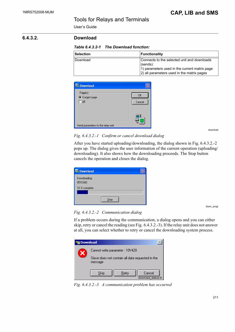
1MRS752008-MUM CAP, LIB and SMS Tools for Relays and TerminalsUser�s Guide
6.4.3.2. Download
download
Fig. 6.4.3.2.-1 Confirm or cancel download dialog
After you have started uploading/downloading, the dialog shown in Fig. 6.4.3.2.-2 pops up. The dialog gives the user information of the current operation (uploading/downloading). It also shows how the downloading proceeds. The Stop button cancels the operation and closes the dialog.
down_progr
Fig. 6.4.3.2.-2 Communication dialog
If a problem occurs during the communication, a dialog opens and you can either skip, retry or cancel the reading (see Fig. 6.4.3.2.-3). If the relay unit does not answer at all, you can select whether to retry or cancel the downloading system process..
Fig. 6.4.3.2.-3 A communication problem has occurred
Table 6.4.3.2-1 The Download function:
Selection FunctionalityDownload Connects to the selected unit and downloads
(sends): 1) parameters used in the current matrix page2) all parameters used in the matrix pages
211

1MRS752008-MUM Tools for Relays and TerminalsUser�s Guide
CAP, LIB and SMS
After the uploading/downloading process is completed, the dialog is closed and the matrices that have been selected at least once are updated.
6.4.4. Help menuThe Help menu contains a general on-line help for the tool functions, information about the related parameters and an About dialog.
Fig. 6.4.4.-1 Help menu
6.4.4.1. Graphical I/O Setting Tool Help
Fig. 6.4.4.1.-1 Graphical I/O Setting Tool Help Viewer dialog
Table 6.4.4.1-1 The Help function:
Selection FunctionalityGraphical I/O Setting Tool Help Opens a help dialog where the functionality of the
tool is generally described.
212

1MRS752008-MUM CAP, LIB and SMS Tools for Relays and TerminalsUser�s Guide
6.4.4.2. Parameter Information
para_info
Fig. 6.4.4.2.-1 Parameter Information dialog
6.4.4.3. About Setting Tool�
Table 6.4.4.2-1 The Parameter Information function:
Selection FunctionalityParameter Information Opens a dialog which describes all the
parameters of the relay that can be set with the Graphical I/O Setting Tool.
Table 6.4.4.3-1 The Setting Tool function:
Selection FunctionalityAbout Setting Tool Gives information about the Graphical I/O Setting
Tool.
213

214
1MRS752008-MUM CAP, LIB and SMS Tools for Relays and TerminalsUser�s Guide
7. DR-Collector Tool
7.1. GeneralDR-Collector Tool is a disturbance recorder tool used for:
� Uploading recordings from the disturbance recorder, also automated uploading in LIB 510/MicroSCADA
� Monitoring� Deleting recordings� Remote triggering� Copying, deleting, moving
Recorder files are created in COMTRADE format.
DR-Collector Tool is used in LIB 510 in MicroSCADA, CAP 501, CAP 505 and in SMS 510 environments.
7.1.1. Communication supportTable 7.1.1-1 Supported communication protocols:
In addition to the protocols above, in LIB 500/510 the following protocols are partly supported for certain relay types with certain restrictions. When using the protocols below, only manual disturbance recording uploading with the DR-Collector Tool is supported, not automated upload.
The DR-Collector Tool that has been integrated into SPA Relay Setting Tool in LIB 510 Version 4.0.2 or older, cannot be used at the same time as the new version of DR-Collector Tool.
CAP 501 SPA, SPA TCP/IP
CAP 505 LON, SPA, SPA TCP/IP
SMS 510 LON, SPA
LIB 500/510 LON, SPA
Table 7.1.1-2 Partly supported communication protocols in LIB 500/510:
Protocol Relay types Condition RemarksIEC 60870-5-101 REF 54x, REM 54x, REC 52x,
RET 54x, REX 52xAll but REC 52x require either a COM 6xx or a KU-2000 gateway
IEC 61850-8 All other RED object types but REC 52x
Only with SYS 600 Requires a SPA-ZC 40x communication gateway
215

1MRS752008-MUM Tools for Relays and TerminalsUser�s Guide
CAP, LIB and SMS
7.1.2. Supported disturbance recorders� MEDREC16 Function Block used in REF 54x, REC 52x, REM 54x, RET 54x
and REX 52x relays� SPCR 8C27 (see Section 7.3.8.3 Transfers menu)� Internal recorders in SPCD 2D55 and SPCD 3D53� Internal recorders in REJ 5xx and REU 5xx relays� Internal recorders in REx 61x relays
7.2. Using DR-Collector Tool
7.2.1. GeneralIf an object is configured in the way that it contains a Disturbance Recorder module/function block, the object in question can be seen in the navigation tree of the Recorder Tool in the DR-Collector Tool. For instance, REF 54x has to be configured to contain MEDREC 16 function block. After that the REF 54x object can be seen in the navigation tree. If you want the SPACOM object to be visible in the navigation tree, SPCR 8C27 has to be visible on the Rack Configuration page in the SPACOM configuration.
For more information on Recorder Tool, see Section 7.3.
7.2.2. Starting DR-Collector Tool The DR-Collector Tool can be started in different ways, depending on the software environment. In LIB 510 in MicroSCADA, DR-Collector Tool is started as described in Section 7.2.2.1.The procedure how to start DR-Collector Tool in CAP 501/505 and in SMS 510 environments is described in Section 7.2.2.2.
7.2.2.1. Starting from LIB 510 in MicroSCADAIn LIB 510, you can start the DR-Collector Tool from the Options Menu in MicroSCADA main view, see the following figure.
OptiMenu
Fig. 7.2.2.1.-1 DR-Collector Tool started from the Options menu
HV/Collect is used for disturbance uploading for high-voltage relays (LIB 520).
If an error message appears on the screen after selecting the DR-Collector Tool in the Options menu, one possible reason is that the DR-Collector Tool has not been installed at all.
216

1MRS752008-MUM CAP, LIB and SMS Tools for Relays and TerminalsUser�s Guide
7.2.2.2. Starting from CAP 501/505 and SMS 510In CAP 501/505 and in SMS 510 environments, start the DR-Collector Tool by selecting it from the System Tools menu (see Fig. 7.2.2.2.-1) or by clicking the respective toolbar button on the Project Structure Navigator dialog (see Fig. 7.2.2.2.-2).
SystMenu
Fig. 7.2.2.2.-1 Starting DR-Collector Tool from the System Tools menu
DRCT_button
Fig. 7.2.2.2.-2 Starting the DR-Collector Tool by clicking the toolbar button
After this the DR-Collector view appears on the screen (see Fig. 7.2.3.-1). DR-Collector Tool is started directly, i.e. no object selection is required.
7.2.3. DR-Collector Tool overviewThe view appearing after the DR-Collector Tool has been started, consists of the following parts:
DRCollTool
Fig. 7.2.3.-1 DR-Collector Tool view
1. Menus2. Toolbar buttons3. Line number4. Date of recording
217

1MRS752008-MUM Tools for Relays and TerminalsUser�s Guide
CAP, LIB and SMS
5. Time of recording6. Location indicating the relay/recorder that originates the recording7. The name of the File that originates the recording8. Identification of the disturbance recorder originating the recording9. Trigger (i.e. the type of signal generating triggering)10.Path indicating the location of recording files (the Path and Location together
specify the directory where the recording file resides)
11.The amount of free space left in drive C. In case there is less than 100 kb free space left in drive C, the commands Refresh, Recorder Tool, Evaluation program and Comment cannot be carried out.
The Options dialog (see Fig. 7.2.4.2.-2) you can open by clicking Options in the View menu. Here you can choose which columns (see Fig. 7.2.3.-1, items 4-9) are to be shown in the DR-Collector Tool main view.
Recording files are named in the following way: YYMDDNNN.EEE. Below you can find the meanings:
YY the year of the time tag in the trigger information (0.99)M the number of the month in the trigger information in the
hexadecimal format (1.C)DD the number of the day in the trigger informationNNN the disturbance number, stored in a decimal formatEXT the extension identifying the format, e.g.
95802001.CFG95802001.DAT
.CFG the extension for COMTRADE header files
.DAT the extension for COMTRADE data files
.INF the extension for COMTRADE information files
.HDR the extension for Comment files
To view the uploaded recordings (that are located in the subdirectory under the Path), click Refresh in the View menu. For more information on this command, please refer to Section 7.2.4.2.
This applies to LIB 510/MicroSCADA only: the name given in square brackets (e.g. [FIMIT-RVS-S11]) indicates the name of the MicroSCADA Base System computer when Remote Monitor is selected. The letter in the beginning of the path (e.g. C, E, H) refers to the drive name of the MicroSCADA Base System computer, not to the drive name of the computer of the Remote Monitor.
218

1MRS752008-MUM CAP, LIB and SMS Tools for Relays and TerminalsUser�s Guide
DR-CollT
Fig. 7.2.3.-2 DR-Collector Tool presented with a list of recordings
7.2.4. MenusThere are four menus in the DR-Collector Tool main view. The commands provided in the menus are described in the following.
7.2.4.1. File menu
Fig. 7.2.4.1.-1 File menu
The File menu provides access to the commands Move, Copy, and Delete. These commands are available only when there are recordings in the DR-Collector Tool main view and at least one recording has been activated (see Fig. 7.2.4.1.-1). One recording may consist of several files (e.g. .DAT, .CFG and HDR files). Due to this, when you select any of the commands Move, Copy and Delete it concerns all files connected to a certain recording.
When using a Remote Monitor, give the same drive name as defined in the MicroSCADA Base System computer into the To-field of the Move/Copy dialogs (see Fig. 7.2.4.1.-2) and (see Fig. 7.2.4.1.-4). Or, you can give the path in the form: \\name of the personal workstation\shared directory. For example, in order to copy a recording from the MicroSCADA Base System computer to your personal workstation:
1. Share the desired directory in your personal workstation.2. Give the path in the form \\name of the personal workstation\shared directory.
219
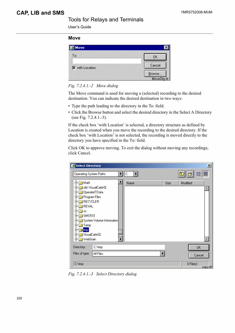
1MRS752008-MUM Tools for Relays and TerminalsUser�s Guide
CAP, LIB and SMS
Move
Fig. 7.2.4.1.-2 Move dialog
The Move command is used for moving a (selected) recording to the desired destination. You can indicate the desired destination in two ways:
� Type the path leading to the directory in the To: field.� Click the Browse button and select the desired directory in the Select A Directory
(see Fig. 7.2.4.1.-3).
If the check box �with Location� is selected, a directory structure as defined by Location is created when you move the recording to the desired directory. If the check box �with Location� is not selected, the recording is moved directly to the directory you have specified in the To: field.
Click OK to approve moving. To exit the dialog without moving any recordings, click Cancel.
Fig. 7.2.4.1.-3 Select Directory dialog
220

1MRS752008-MUM CAP, LIB and SMS Tools for Relays and TerminalsUser�s Guide
Copy
Fig. 7.2.4.1.-4 Copy dialog
The Copy command is used for copying a (selected) recording to the desired destination. You can indicate the desired destination in two ways:
� Type the path leading to the directory in the To: field.� Click the Browse button and select the desired directory in the Select A Directory
(see Fig. 7.2.4.1.-3).
If the check box �with Location� is selected, a directory structure as defined by Location is created when you copy the recording to the desired directory. If the check box �with Location� is not selected, the recording is copied directly under the directory you have specified in the To: field.
Click OK, to approve copying. To exit the dialog without approving copying, click Cancel.
DeleteThe Delete command deletes the selected file(s) in the directory. Click Yes to delete the selected file/s. Click No to exit the dialog without deleting any file(s).
Fig. 7.2.4.1.-5 DR-Collector Tool dialog
ExitTo close the DR-Collector Tool, select the Exit command in the File menu.
221

1MRS752008-MUM Tools for Relays and TerminalsUser�s Guide
CAP, LIB and SMS
7.2.4.2. View menuThe View menu contains the commands Refresh and Options.
Fig. 7.2.4.2.-1 View menu
RefreshThe Refresh command in the View Menu can be used for searching the files defined in the Path in the lower part of the dialog (see Fig. 7.2.3.-1 and 7.2.3.-2). The command shows them on the screen if the files are recording files. This is not, however, an automatic operation when starting the program. Therefore, it is suggested to use the Refresh command.
OptionsClick the View menu and select Options.
Fig. 7.2.4.2.-2 Options dialog
The first field in the upper part of the dialog shows which disturbance recording format(s) is (are) supported. In this example, only the COMTRADE format is supported.
222
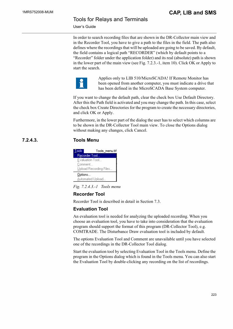
1MRS752008-MUM CAP, LIB and SMS Tools for Relays and TerminalsUser�s Guide
In order to search recording files that are shown in the DR-Collector main view and in the Recorder Tool, you have to give a path to the files in the field. The path also defines where the recordings that will be uploaded are going to be saved. By default, the field contains a logical path �RECORDER� (which by default points to a �Recorder� folder under the application folder) and its real (absolute) path is shown in the lower part of the main view (see Fig. 7.2.3.-1, item 10). Click OK or Apply to start the search.
If you want to change the default path, clear the check box Use Default Directory. After this the Path field is activated and you may change the path. In this case, select the check box Create Directories for the program to create the necessary directories, and click OK or Apply.
Furthermore, in the lower part of the dialog the user has to select which columns are to be shown in the DR-Collector Tool main view. To close the Options dialog without making any changes, click Cancel.
7.2.4.3. Tools Menu
Fig. 7.2.4.3.-1 Tools menu
Recorder ToolRecorder Tool is described in detail in Section 7.3.
Evaluation ToolAn evaluation tool is needed for analyzing the uploaded recording. When you choose an evaluation tool, you have to take into consideration that the evaluation program should support the format of this program (DR-Collector Tool), e.g. COMTRADE. The Disturbance Draw evaluation tool is included by default.
The options Evaluation Tool and Comment are unavailable until you have selected one of the recordings in the DR-Collector Tool dialog.
Start the evaluation tool by selecting Evaluation Tool in the Tools menu. Define the program in the Options dialog which is found in the Tools menu. You can also start the Evaluation Tool by double-clicking any recording on the list of recordings.
Applies only to LIB 510/MicroSCADA! If Remote Monitor has been opened from another computer, you must indicate a drive that has been defined in the MicroSCADA Base System computer.
223

1MRS752008-MUM Tools for Relays and TerminalsUser�s Guide
CAP, LIB and SMS
CommentThe option Comment opens a dialog in which you can type a more detailed analysis of a recording etc. The name of the file is otherwise the same as the name of the recording, except that it is provided with the extension HDR.
CommentDig
Fig. 7.2.4.3.-2 Comment dialog
Upload Recording FilesThis function can mainly be used when two SMS 510 systems are connected via either a LAN or a remote/RAS connection. If the local project is selected in the Project Structure Navigator, the DR-Collector Tool works as described in Section later on in this document
OptionsThe Evaluation Tool for evaluating and drawing of disturbance recordings can be defined from the Options dialog. You can also define the recording path for remote connections. If the default option DistDraw32.exe is ok, just confirm it by pressing OK.
Fig. 7.2.4.3.-3 Options dialog
224
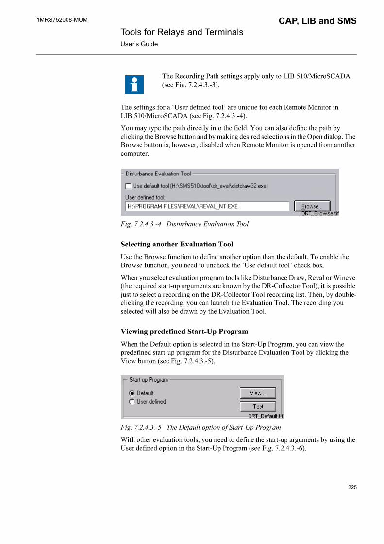
1MRS752008-MUM CAP, LIB and SMS Tools for Relays and TerminalsUser�s Guide
The settings for a �User defined tool� are unique for each Remote Monitor in LIB 510/MicroSCADA (see Fig. 7.2.4.3.-4).
You may type the path directly into the field. You can also define the path by clicking the Browse button and by making desired selections in the Open dialog. The Browse button is, however, disabled when Remote Monitor is opened from another computer.
Fig. 7.2.4.3.-4 Disturbance Evaluation Tool
Selecting another Evaluation ToolUse the Browse function to define another option than the default. To enable the Browse function, you need to uncheck the �Use default tool� check box.
When you select evaluation program tools like Disturbance Draw, Reval or Wineve (the required start-up arguments are known by the DR-Collector Tool), it is possible just to select a recording on the DR-Collector Tool recording list. Then, by double-clicking the recording, you can launch the Evaluation Tool. The recording you selected will also be drawn by the Evaluation Tool.
Viewing predefined Start-Up ProgramWhen the Default option is selected in the Start-Up Program, you can view the predefined start-up program for the Disturbance Evaluation Tool by clicking the View button (see Fig. 7.2.4.3.-5).
Fig. 7.2.4.3.-5 The Default option of Start-Up Program
With other evaluation tools, you need to define the start-up arguments by using the User defined option in the Start-Up Program (see Fig. 7.2.4.3.-6).
The Recording Path settings apply only to LIB 510/MicroSCADA (see Fig. 7.2.4.3.-3).
225
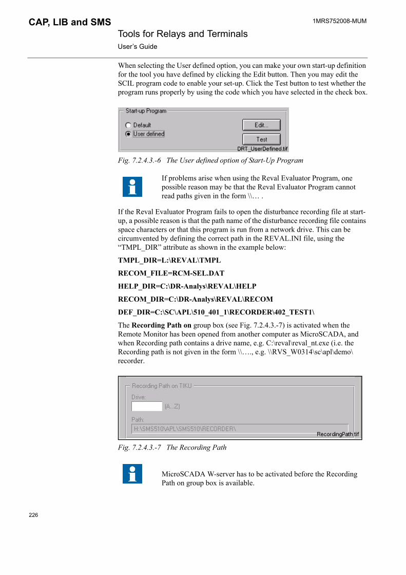
1MRS752008-MUM Tools for Relays and TerminalsUser�s Guide
CAP, LIB and SMS
When selecting the User defined option, you can make your own start-up definition for the tool you have defined by clicking the Edit button. Then you may edit the SCIL program code to enable your set-up. Click the Test button to test whether the program runs properly by using the code which you have selected in the check box.
Fig. 7.2.4.3.-6 The User defined option of Start-Up Program
If the Reval Evaluator Program fails to open the disturbance recording file at start-up, a possible reason is that the path name of the disturbance recording file contains space characters or that this program is run from a network drive. This can be circumvented by defining the correct path in the REVAL.INI file, using the �TMPL_DIR� attribute as shown in the example below:
TMPL_DIR=L:\REVAL\TMPL
RECOM_FILE=RCM-SEL.DAT
HELP_DIR=C:\DR-Analys\REVAL\HELP
RECOM_DIR=C:\DR-Analys\REVAL\RECOM
DEF_DIR=C:\SC\APL\510_401_1\RECORDER\402_TEST1\
The Recording Path on group box (see Fig. 7.2.4.3.-7) is activated when the Remote Monitor has been opened from another computer as MicroSCADA, and when Recording path contains a drive name, e.g. C:\reval\reval_nt.exe (i.e. the Recording path is not given in the form \\�., e.g. \\RVS_W0314\sc\apl\demo\recorder.
Fig. 7.2.4.3.-7 The Recording Path
If problems arise when using the Reval Evaluator Program, one possible reason may be that the Reval Evaluator Program cannot read paths given in the form \\� .
MicroSCADA W-server has to be activated before the Recording Path on group box is available.
226

1MRS752008-MUM CAP, LIB and SMS Tools for Relays and TerminalsUser�s Guide
Enter the drive name of the mapped directory into the Drive field. The path appears in the Path field. The path is used when you start the Disturbance Evaluation Tool. The selected disturbance recording is opened in the Disturbance Evaluation Tool from the computer defined in the upper part of the group box (e.g.TIKU).
If the recording path to the directory is not found under the given drive, check that the given drive has been mapped, and that one of the directories of the path is defined to have shared writing rights.
The shared directory has to be mapped into the computer from where a Remote Monitor is opened.
To accept changes, click OK. To exit the dialog without accepting the made changes, click Cancel.
Automated upload
The automated upload is monitored and configured by the Automated Upload dialog. The status of the automated upload can be:
� Automated upload not in use � Automated upload temporarily not in use � Automated upload in standby � Automated upload in progress
The other fields can be available or unavailable depending on status.
Automated upload not in useIf the Automated Upload is configured in a way that it does not start uploading automatically, the status �Automated upload not in use� is shown in the Status field (see Fig. 7.2.4.3.-8). You can configure the automated upload in a dialog that opens when you click the Settings button.
This function is only available in LIB 510 in the MicroSCADA environment.
Changing the settings requires authorization level 1.
227
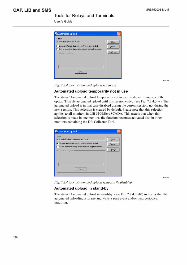
1MRS752008-MUM Tools for Relays and TerminalsUser�s Guide
CAP, LIB and SMS
AULniu
Fig. 7.2.4.3.-8 Automated upload not in use
Automated upload temporarily not in useThe status �Automated upload temporarily not in use� is shown if you select the option �Disable automated upload until this session ended�(see Fig. 7.2.4.3.-9). The automated upload is in that case disabled during the current session, not during the next session. This selection is cleared by default. Please note that this selection applies to all monitors in LIB 510/MicroSCADA. This means that when this selection is made in one monitor, the function becomes activated also in other monitors containing the DR-Collector Tool.
AutoUpl
Fig. 7.2.4.3.-9 Automated upload temporarily disabled
Automated upload in stand-byThe status �Automated upload in stand-by� (see Fig. 7.2.4.3.-10) indicates that the automated uploading is in use and waits a start event and/or next periodical inquiring.
228

1MRS752008-MUM CAP, LIB and SMS Tools for Relays and TerminalsUser�s Guide
AULStaBy
Fig. 7.2.4.3.-10 Automated upload in standby
Automated upload in progressProgress of uploading is monitored in the �Upload in progress� group box (see Fig. 7.2.4.3.-11). This group contains exactly the same fields as the progress indicator of the visible DR-Collector Tool. You can interrupt the current uploading by clicking Stop.
This dialog is opened automatically by default whenever you start the automated upload. However, automatic opening can be disabled when you select the option �Do not open this dialog automatically during this session�.
AutoUL2
Fig. 7.2.4.3.-11 Automated upload in progress dialog
The DR-Collector Tool uploads only from one Disturbance Recorder at a time.
QueueThe uploading requests, that are made while uploading is still under process, are put in a queue. This queue can be seen in the Queue dialog. The queue is deleted by clicking Clear.
229

1MRS752008-MUM Tools for Relays and TerminalsUser�s Guide
CAP, LIB and SMS
QueueDlg
Fig. 7.2.4.3.-12 Recorders in Queue dialog
Settings
AUSetSta1
Fig. 7.2.4.3.-13 Automated Upload - Settings dialog/Start page
The configuration of automated upload is done on the Start page of the Settings dialog. Open the Settings dialog by clicking the Settings button in the Automated upload dialog. You can define the uploading to start regularly at certain periods and/or on the basis of certain events.
The Settings dialog consists of two pages: Start and General. The Start page contains two group boxes: Starts on periodic inquiry, and Starts on Events (see Fig. 7.2.4.3.-13). If you clear both check boxes �Starts on periodic inquiry� and �Starts on events�, the automated upload is disabled.
If you check the Starts on periodic inquiry check box (see Fig. 7.2.4.3.-13), you can set its attributes. All recorders are always uploaded on the basis of the definitions made in the fields below. The following alternatives are available for cycle:
230

1MRS752008-MUM CAP, LIB and SMS Tools for Relays and TerminalsUser�s Guide
� Fixed intervals, no synchronization� Absolute point of time, once an Hour � Absolute point of time, once a Day � Absolute point of time, once a Week � Absolute point of time, once a Month
Define the cycle by selecting the appropriate alternative in the Cycle drop-down combo box. You can define the date and time with the help of the drop-down arrows. However, the Date and Time fields may be available or unavailable depending on which option you have selected in the Cycle drop-down combo box.
In the Starts on Events group box (see Fig. 7.2.4.3.-13) the objects (relays) that contain disturbance recorder are listed on the left side of the table. If you select the Starts on Events check box, the events that trigger uploading are defined in the field in the middle of the table.
The recorder table is user controlled. If the Starts on Events check box is already checked, but the table is dimmed, a manual refresh of the table must be done by pressing the Refresh button. After this the table will be accessible for editing.
Automated upload can be defined separately for every event. The field in the right side indicates whether the automated uploading of an event has been defined to be in use or not. You can change the state of a single event by double-clicking the column In Use. The text �Yes� and �No� changes automatically. However, the state in the In Use field may also be e.g. Error 1 when you click the Apply button. If you select this field (Error 1), the state is changed into Yes or No. The error codes are the following.
Table 7.2.4.3-1 Error codes and their explanations:
Error Code Explanation
1 Initialization has failed due to time out.
3 Protocol module cannot be loaded. Communication configuration is missing or has not been configured properly.
101 Process object address overlap. This status occurs in situations when trying to create a process object by using the object address (OA) and unit number (UN) that are already used by another logical name (LN). Existing process object must be removed before new configuration can be created.
102 Relay configuration does not contain the requested function block.
103 Base system configuration has not been configured properly. The definition of the STA object has probably been changed or it is missing, and therefore, event handling objects could not be created.
The option �Yes� means that the event is sent to the Event List regardless of the settings previously defined for the event in the Event Editor. In case the state of a single event is �Yes� in the In Use column, but the state of that same event is changed into �No� in the Event Editor, the state is changed to �No� also in the In Use column.
231
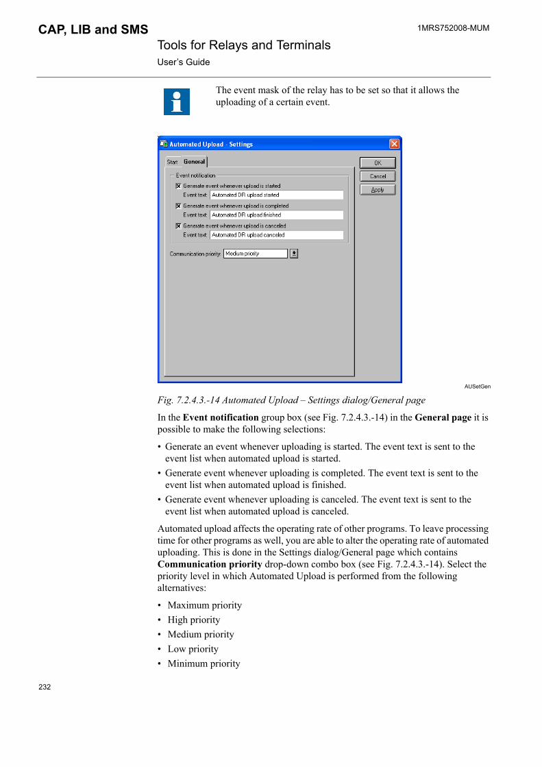
1MRS752008-MUM Tools for Relays and TerminalsUser�s Guide
CAP, LIB and SMS
AUSetGen
Fig. 7.2.4.3.-14 Automated Upload � Settings dialog/General page
In the Event notification group box (see Fig. 7.2.4.3.-14) in the General page it is possible to make the following selections:
� Generate an event whenever uploading is started. The event text is sent to the event list when automated upload is started.
� Generate event whenever uploading is completed. The event text is sent to the event list when automated upload is finished.
� Generate event whenever uploading is canceled. The event text is sent to the event list when automated upload is canceled.
Automated upload affects the operating rate of other programs. To leave processing time for other programs as well, you are able to alter the operating rate of automated uploading. This is done in the Settings dialog/General page which contains Communication priority drop-down combo box (see Fig. 7.2.4.3.-14). Select the priority level in which Automated Upload is performed from the following alternatives:
� Maximum priority� High priority� Medium priority� Low priority� Minimum priority
The event mask of the relay has to be set so that it allows the uploading of a certain event.
232

1MRS752008-MUM CAP, LIB and SMS Tools for Relays and TerminalsUser�s Guide
The default alternative for communication priority is Medium priority. Maximum priority means that recordings are read as quickly as possible, and Minimum priority means that recordings have the lowest priority, and processing time is left for other programs, too. In other words, the lower priority selected in the drop-down combo box, the slower uploading.
7.2.4.4. Help menu
Fig. 7.2.4.4.-1 Help menu
About DR-Collector ToolThe dialog About DR-Collector Tool contains information on the current version of the DR-Collector Tool. Click OK to close the dialog.
7.2.5. Toolbar buttonsThe most important menu functions are also available as toolbar buttons. These functions are described in detail in Section 7.2.4.
Table 7.2.5-1 DR-Collector Tool�s toolbar buttons:
Button Functionality
Exit (for exiting the main program)
Copy (for copying a record to a desired destination)
Delete (for deleting the selected files; requires authorization level 1)
Refresh (for searching and showing the files defined in a dialog)
Recorder Tool (for opening the Recorder Tool program)
Evaluation program (for opening the Evaluation Program for a recorded file)
Comment (opens a dialog for writing a detailed comment)
Remote connections(for making a connection between the workstation and the system that contains a recording)
233

1MRS752008-MUM Tools for Relays and TerminalsUser�s Guide
CAP, LIB and SMS
7.3. Recorder Tool
7.3.1. GeneralAs described in Section 7.2.4.3, start the Recorder Tool by selecting Recorder Tool in the Tools menu in the DR-Collector Tool.
The Recorder Tool contains different kinds of functions depending on the recorder, e.g. monitoring, manual uploading of functions, such as remote triggering, delete recording, and possibly other special functions, too.
7.3.2. FunctionsInformation given in the Recorder Tool dialog (see Fig. 7.3.2.-1, items 4 and 5) depends on what kind of relay/recorder you have selected. When entering the Recorder Tool, there are no monitoring fields on the right in the dialog (see Fig. 7.3.2.-1, items 4 and 5). Only when you select a recorder in the tree structure, the monitoring fields on the right are visible.
Information given in the monitoring fields depends on the recorder. The example given below concerns disturbance recorders configured for RED 500 relays. In addition to the standard menus, there may also be other menus available depending on the recorder.
All installed relays that contain a disturbance recorder are shown in the tree structure.
The object Eastwick in the tree structure corresponds to the information given in the Location column found in the DR-Collector Tool main view.
234
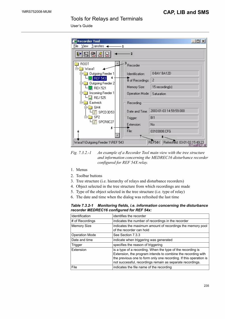
1MRS752008-MUM CAP, LIB and SMS Tools for Relays and TerminalsUser�s Guide
Fig. 7.3.2.-1 An example of a Recorder Tool main view with the tree structure and information concerning the MEDREC16 disturbance recorder configured for REF 54X relay.
1. Menus2. Toolbar buttons3. Tree structure (i.e. hierarchy of relays and disturbance recorders)4. Object selected in the tree structure from which recordings are made5. Type of the object selected in the tree structure (i.e. type of relay)6. The date and time when the dialog was refreshed the last time
Table 7.3.2-1 Monitoring fields, i.e. information concerning the disturbance recorder MEDREC16 configured for REF 54x:Identification identifies the recorder# of Recordings indicates the number of recordings in the recorderMemory Size indicates the maximum amount of recordings the memory pool
of the recorder can holdOperation Mode See Section 7.3.3Date and time indicate when triggering was generatedTrigger specifies the reason of triggeringExtension is a type of a recording. When the type of the recording is
Extension, the program intends to combine the recording with the previous one to form only one recording. If this operation is not successful, recordings remain as separate recordings.
File indicates the file name of the recording
235

1MRS752008-MUM Tools for Relays and TerminalsUser�s Guide
CAP, LIB and SMS
7.3.3. RE_54_ transient disturbance recorder (REF 54x, REM 54x,REC 523, RET 54x)There are three types of Operation Modes (see Fig. 7.3.2.-1, item 4); Saturation mode, Overwrite mode, and Extension mode. For more information on the different modes, please refer to the RE_54_ Transient Disturbance Recorder (MEDREC16) manual.
7.3.4. Disturbance recorder REX 521
Fig. 7.3.4.-1 An example of a Recorder Tool main view with the tree structure and information concerning the internal disturbance recorder of REX 521 relay module.
Table 7.3.4-1 Description of Monitoring fields in Fig. 7.3.4.-1:Identification identifies the recorder# of Recordings indicates the number of recordings in the recorderMemory Size indicates the maximum amount of recordings the memory
pool of the recorder can holdOperation Mode indicates the measurement status of the recorder, see
Section 7.3.3 Date and time indicate when triggering was generatedTrigger specifies the reason of triggeringExtension is a type of a recording. When the type of the recording is
Extension, the program intends to combine the recording with the previous one to form only one recording. If this operation is not successful, recordings remain as separate recordings.
File indicates the file name of the recording
236
1MRS752008-MUM CAP, LIB and SMS Tools for Relays and TerminalsUser�s Guide
7.3.5. Disturbance recorder SPCR 8C27
Fig. 7.3.5.-1 An example of a Recorder Tool main view with the tree structure and information concerning the SPCR 8C27 disturbance recorder configured for SPACOM relay.
Table 7.3.5-1 Description of Monitoring fields in Fig. 7.3.5.-1:Identification identifies the recorder# of Recordings indicates the number of recordings in the recorderFree Memory indicates the available free recording memory that the
recorder try to maintain.REC = recordings, CHA = Channels and BLO blocks shows the free amount of entities
Status indicates the measurement status of the recorderDate and time indicate when triggering was generatedTrigger specifies the reason of triggeringFile indicates the file name of the recording
237

1MRS752008-MUM Tools for Relays and TerminalsUser�s Guide
CAP, LIB and SMS
7.3.6. Internal disturbance recorders SPCD 2D55, SPCD 3D53
Fig. 7.3.6.-1 An example of a Recorder Tool main view with the tree structure and information concerning the SPCD 3D53 relay module.
Remote triggering is not available, because SPCD 2D55 and SPCD 3D53 do not support remote triggering.
Table 7.3.6-1 Description of Monitoring fields in Fig. 7.3.6.-1:Identification identifies the recorder# of Recordings indicates the number of recordings in the recorderDate and time indicate when triggering was generatedTrigger specifies the reason of triggeringFile indicates the file name of the recording
238
1MRS752008-MUM CAP, LIB and SMS Tools for Relays and TerminalsUser�s Guide
7.3.7. Internal disturbance recorders REU5xx, REJ 5xx, REx 61x
Fig. 7.3.7.-1 An example of a Recorder Tool main view with the tree structure and information concerning the internal disturbance recorder of REJ 5xx (or REx 61x) relay modules.
7.3.8. MenusThe Recorder Tool view contains three standard menus which are presented in the following sections.
7.3.8.1. File menu
FileExit
Fig. 7.3.8.1.-1 File menu
Table 7.3.7-1 Description of Monitoring fields in Fig. 7.3.7.-1:Identification identifies the recorder# of Recordings indicates the number of recordings in the recorderDate and time indicate when triggering was generatedTrigger specifies the reason of triggeringFile indicates the file name of the recording
239

1MRS752008-MUM Tools for Relays and TerminalsUser�s Guide
CAP, LIB and SMS
ExitExit from the Recorder Tool dialog is provided by the Exit command in the File menu.
7.3.8.2. View menu
ViewMen2
Fig. 7.3.8.2.-1 View menu
RefreshThe Refresh command is available in the View menu only if you have selected a recorder in the tree structure. The Recorder Tool reads necessary information from the disturbance recorder in order for the recorder tool dialog to be updated.
7.3.8.3. Transfers menu
Transfers1
Fig. 7.3.8.3.-1 Transfers menu
Reservation of communicationThe Recorder Tool reserves communication to the selected object upon a transaction. The transaction can be whatever communication between the tool and the recorder (Refresh, Upload etc.). Communication is reserved until either the tool is closed, or until fifteen (15) minutes has elapsed since the transaction ended, after which the communication will be automatically released.
Upload RecordingUploading concerns the recorders that are shown under the selected object in the tree structure. In case you have selected the root in the tree structure, uploading concerns all recorders in the tree structure below the root. Therefore, click Yes to upload all recordings from the allocated recorders under the root in the tree structure. Click No to exit the dialog without uploading any recordings.
Authorization level 1 is required to execute the "Upload recording", "Delete recording" and "Remote triggering" functions. If the "MV_RELAYS" authorization group has been defined in the user management, then the DR-Collector Tool uses an authorization level defined for that group. Otherwise it uses the "GENERAL" group.
240
1MRS752008-MUM CAP, LIB and SMS Tools for Relays and TerminalsUser�s Guide
UplRec
Fig. 7.3.8.3.-2 Upload Recording dialog when the Root is selected
Applies to SPCR 8C27: Uploading of disturbance recordings from SPCR 8C27 is performed over the SPA bus, i.e. using the rear connector of the host relay or the SPTO front connector (SPAC 500/600 series feeder terminals). The uploading of disturbance recordings through the front connector of the SPCR 8C27 is not supported.
In case you have selected one of the recorders below the Root in the tree structure, uploading concerns only the recordings registered by that specific recorder.
UplRec1
Fig. 7.3.8.3.-3 Upload Recording dialog when a recorder is selected
In the Upload Recording Dialog (see Fig. 7.3.8.3.-3), you may choose the following:
� Upload of all recordings from the selected recorder module, click the Upload All button.
� Upload of one recording from the selected recorder module, click the Upload One button.
� To exit the dialog without uploading any recordings, click Cancel.
The button Upload One may also be clicked repeatedly, i.e. several recordings can be uploaded one by one by clicking the button repeatedly.
Applies to MEDREC16 only: If you interrupt the uploading procedure, the recording remains locked in the transfer buffer. This recording will not be deleted if you have emptied the memory pool by using the relevant buttons in the front panel of the relay, or when the operation mode is Overwrite. If you wish to delete a recording from the memory pool, it is recommended to use the Delete Recording function of the DR-Collector Tool.
241

1MRS752008-MUM Tools for Relays and TerminalsUser�s Guide
CAP, LIB and SMS
Remote TriggeringDisturbance Recording is triggered by a remote command.
Remote triggering concerns the recorders that are shown under the selected object in the tree structure. If you have selected the Root in the tree structure, remote triggering concerns all recorders in the tree structure below the Root. Click Yes to trigger remotely all allocated recorders under the object Root in the tree structure. Click No to exit the dialog without triggering any recorders.
RemTrig
Fig. 7.3.8.3.-4 Remote Triggering dialog when the Root is selected
RemTrig2
Fig. 7.3.8.3.-5 Remote Triggering dialog when a recorder is selected
If you have selected one of the recorders below the Root, only the specific recorder can be triggered remotely. Click Yes to trigger the selected recorder module remotely. Click No to exit the dialog without triggering the selected recorder module remotely.
Delete RecordingDelete recording concerns the recorders that are shown under the selected object in the tree structure. If you have selected the Root in the tree structure, the command Delete Recording concerns all recorders in the tree structure below the root. Click Yes to delete all recordings from the allocated recorders under Root in the tree structure. Click No to exit the dialog without deleting any recordings.
DelRec
Fig. 7.3.8.3.-6 Delete Recording dialog when the Root is selected
In case one of the recorders below the root has been selected, the Delete Recording command concerns only recordings registered by the specific recorder.
242

1MRS752008-MUM CAP, LIB and SMS Tools for Relays and TerminalsUser�s Guide
DelRec1
Fig. 7.3.8.3.-7 Delete Recording dialog when a recorder in the tree structure is selected.
In the Delete Recording Dialog (see Fig. 7.3.8.3.-7), you may choose the following:
� Delete all recordings from the selected recorder module, click the Delete All button.
� Delete of one recording from the selected recorder module, click the Delete One button.
� To exit the dialog without deleting any recordings, click Cancel.
Delete Recordings after UploadingIn normal use the recordings are automatically deleted from the recorders after a successful uploading. This way the recorder memory does not become full and the already uploaded recordings are not uploaded again.
However, for some special purpose this deleting can temporarily be switched off by selecting Delete Recordings after Uploading in the Transfers menu. When this toggle menu item is switched off, the same recordings can be uploaded several times again. Due to the temporary nature of usage, the Delete Recordings after Uploading is always on when opening the DR-Collector Tool.
DelRecaUpl
Fig. 7.3.8.3.-8 Warning dialog when recordings are selected not to be deleted
Note that if the Upload All button is clicked when uploading with the Delete Recordings after Uploading is switched off, the upload operation will be endless. For that reason the warning dialog below is shown when toggling off the option.
243
1MRS752008-MUM Tools for Relays and TerminalsUser�s Guide
CAP, LIB and SMS
Notification dialogIf you have selected a command that includes more than one recorder in the following dialogs: Upload Recording, Remote Triggering or Delete Recording, a notification dialog appears on the screen (see Fig. 7.3.8.3.-9). This notification dialog shows all recorders (i.e. objects) included in the command. It also shows the status, i.e. whether the action of the command was successful or not.
UplNot
Fig. 7.3.8.3.-9 Upload Recording - Notification dialog
7.3.8.4. Reset menuReset Menu is available when you have selected SPACOM object and SPCR 8C27 module in the Recorder Tool.
ResetMen
Fig. 7.3.8.4.-1 Reset menu
Unit (warm start-up)Reset Unit (warm start-up) restarts the recorder without deleting existing recordings.
Monitored signalsThe recorder records minimum and maximum values and gives time stamps for them. The minimum and maximum values and their time stamps are read from the parameters V2 � V14. The Reset Monitor signals option resets time stamps and values, i.e. the minimum value 0, maximum value 0 and time stamp 0 are written in the parameters V2 � V14.
7.3.8.5. Toolbar buttonsThe most important menu commands are also presented as toolbar buttons
244

1MRS752008-MUM CAP, LIB and SMS Tools for Relays and TerminalsUser�s Guide
Table 7.3.8.5-1 Recorder Tool�s standard toolbar buttons:
In addition to the standard buttons presented above, there may also be other buttons and/or objects depending on the recorder.
7.4. Using DR-Collector Tool over a remote connection
If a remote connection has been established, the following functions are enabled; the DR-Collector Tool shows also the header information of the new recordings located on the remote station (see Fig. 7.4.-1). The disturbance recordings that are located in the remote SMS 510 computer are marked with the [remote] keyword and the recordings that reside on the local computer are marked with the [local] keyword.
You can upload the [remote] disturbance recordings from the remote station/SMS by selecting Upload Recording Files on the Tools menu or by clicking the respective toolbar button. You can either copy or move the disturbance recordings from the remote station (see Fig. 7.4.-2). A remotely stored recording can be uploaded only once regardless of the selected option (copy/move).
Internally, the DR-Collector Tool maintains a locally stored list, which contains the new recordings that the tool has uploaded from the disturbance recorders. When a connection between two SMS 510 systems has been established, the local DR-Collector Tool reads the list on the remote computer and indicates the remotely stored recordings using the keyword [remote]. Upon completion of every successful recording upload from a remote to local SMS 510, the list on the remote computer is cleared. This means that the recordings are available for upload only once.
Button Functionality
Exit
Refresh
Upload Recording
Remote Triggering
Delete Recording
The functionality described below is supported only when two SMS 510 systems are interconnected via LAN or RAS. The disturbance recordings cannot be uploaded from the SYS 500/LIB 5xx or COM 500 to the SMS 510. However, communication from the SMS 510 to the relays is established via SYS 500/LIB 5xx and COM 500, if their application has been built using LIB 500/5x0.
245
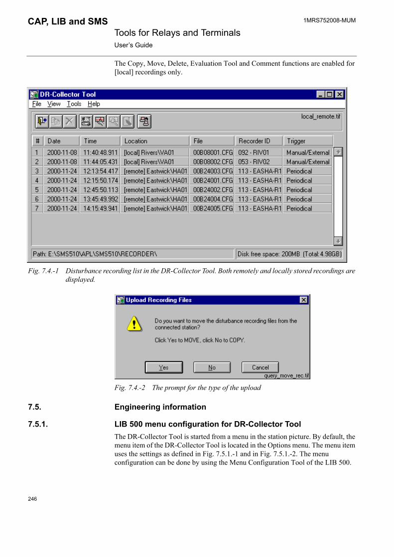
1MRS752008-MUM Tools for Relays and TerminalsUser�s Guide
CAP, LIB and SMS
The Copy, Move, Delete, Evaluation Tool and Comment functions are enabled for [local] recordings only.
Fig. 7.4.-1 Disturbance recording list in the DR-Collector Tool. Both remotely and locally stored recordings are displayed.
Fig. 7.4.-2 The prompt for the type of the upload
7.5. Engineering information
7.5.1. LIB 500 menu configuration for DR-Collector ToolThe DR-Collector Tool is started from a menu in the station picture. By default, the menu item of the DR-Collector Tool is located in the Options menu. The menu item uses the settings as defined in Fig. 7.5.1.-1 and in Fig. 7.5.1.-2. The menu configuration can be done by using the Menu Configuration Tool of the LIB 500.
246

1MRS752008-MUM CAP, LIB and SMS Tools for Relays and TerminalsUser�s Guide
Fig. 7.5.1.-1 Add Menu Item dialog
By clicking the Advanced button in Fig. 7.5.1.-1, the following dialog appears on the screen:
Fig. 7.5.1.-2 Advanced settings for the menu item
7.5.2. Command proceduresAutomated upload uses some command procedures that are executed as parallel tasks.
The default queue for automated uploading is six (PE = 6). If this queue is already in use for time critical objects, the value of this attribute can be changed but NOT set to 0. To change the default value 6, open the following file: \Sc\Lib4\base\bbone\use\BGU_Product.ini, and change the value of the following attribute: DRCT_Parallel_Queue = 6.
The value of the Parallel queues attribute in the base system configuration may not be lower than the value of the PQ attribute (APL:BPQ).
247

1MRS752008-MUM Tools for Relays and TerminalsUser�s Guide
CAP, LIB and SMS
7.5.3. Configuring SRIO parameters when connected to MicroSCADAIf recordings are read through SRIO, SRIO�s timeout value must be increased from 50 ms to 300 ms. The disturbance recorder has several exceptionally long parameter values that can cause communication problems, if the timeout default value (50 ms) is used. Please refer to SETUP 2 command in the programming manual for SRIO 1000M and 500M for more details of this command.
7.5.4. Other information
Only SPCR 8C27 is supported, not SPCR 8C19.
248
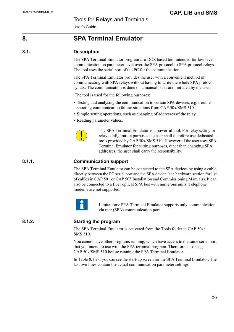
1MRS752008-MUM CAP, LIB and SMS Tools for Relays and TerminalsUser�s Guide
8. SPA Terminal Emulator
8.1. DescriptionThe SPA Terminal Emulator program is a DOS based tool intended for low level communication on parameter level over the SPA protocol to SPA protocol relays. The tool uses the serial port of the PC for the communication.
The SPA Terminal Emulator provides the user with a convenient method of communicating with SPA relays without having to write the whole SPA protocol syntax. The communication is done on a manual basis and initiated by the user.
The tool is used for the following purposes:
� Testing and analysing the communication to certain SPA devices, e.g. trouble shooting communication failure situations from CAP 50x/SMS 510.
� Simple setting operations, such as changing of addresses of the relay.� Reading parameter values.
8.1.1. Communication supportThe SPA Terminal Emulator can be connected to the SPA devices by using a cable directly between the PC serial port and the SPA device (see hardware section for list of cables in CAP 501 or CAP 505 Installation and Commissioning Manuals). It can also be connected to a fiber optical SPA bus with numerous units. Telephone modems are not supported.
8.1.2. Starting the programThe SPA Terminal Emulator is activated from the Tools folder in CAP 50x/SMS 510.
You cannot have other programs running, which have access to the same serial port that you intend to use with the SPA terminal program. Therefore, close e.g. CAP 50x/SMS 510 before running the SPA Terminal Emulator.
In Table 8.1.2-1 you can see the start-up screen for the SPA Terminal Emulator. The last two lines contain the actual communication parameter settings.
The SPA Terminal Emulator is a powerful tool. For relay setting or relay configuration purposes the user shall therefore use dedicated tools provided by CAP 50x/SMS 510. However, if the user uses SPA Terminal Emulator for setting purposes, other than changing SPA addresses, the user shall carry the responsibility.
Limitations: SPA Terminal Emulator supports only communication via rear (SPA) communication port.
249

1MRS752008-MUM Tools for Relays and TerminalsUser�s Guide
CAP, LIB and SMS
Exiting the programTo exit the SPA Terminal session, press <Ctrl> Z followed by <Enter>.
8.1.3. Communication setup The communication settings are changed by typing the following: �- + corresponding letter + new value (-ParametreNew_Value)�
Parameters that can be set:
� The SPA slave address to which communication will take place� Baud rate used� The communication port of the computer� Databits� Parity
Example: -a29 changes the settings of the SPA Terminal Emulator to use address 29 for all SPA messages sent, until other is defined.
After the setting of the communication parameters is completed, the communication to the SPA device can begin, provided that the SPA Terminal is properly connected to the SPA device.
8.1.4. Reading and sending of SPA messagesMessages are sent either to the module as a read (R = Read) or a write (W = Write) message. Write messages change the actual parameter setting in the SPA device.
Give the messages you want to send without start characters, address or checksum. These are added automatically by the tool.
See also the communication examples in Section 8.1.5.
Table 8.1.2-1 The standard start-up screen for the SPA Terminal Emulator: SPA program for SPACOM communication. Version 4.0
Type SPA commands without address and checksum. For example: RF (not >3RF:XX).To change a parameter value on line type -ParametreNew_Valuee.g. -a23 to change SPA address or -b1200 to change baud rate.To exit type CTRL/Z ENTERCom1 9600 bps 7 dbits parity=e No handshake SPA-addr=1 multi_line_answer=2 lower_case=0
Some parameters depending on the SPA device are protected by a remote setting password (concerns only the Write function). Refer to the parameter listings in the related SPA device manuals.
250

1MRS752008-MUM CAP, LIB and SMS Tools for Relays and TerminalsUser�s Guide
In certain types of relay modules, the settings have to be stored by a separate store command: WV151:1. This concerns, for example, SACO annunciators and SPTO control modules.
8.1.5. SPA Terminal Emulator examplesThis section illustrates the communication between a SPA device e.g. a SPAJ 140 C and the SPA Terminal Emulator. Refer to the SPA device manual for listing of all available parameters, with settings, ranges and identity.
R = Read, i.e. read parameters from the module, W = Write, i.e. send new settings for a parameter in the module. Capital letters may also be used.
Conditions in the example:
A SPAJ 140 C relay with the module SPCJ 4D29 with SPA slave address 12 is connected via a SPA-ZP-5A3 cable to the COM2 port of the PC. The example features also a change of the address to 43.
To avoid mixing the comments with the original texts presented in the SPA Terminal Emulator, the comments are written in bold.
Default tool settingsCOM1 9600 bps 7 dbits paritet=e No handshake SPA-addr=1
multi_line_answer=2 lower_case=0
Change the communication address to 12, (SPA Device with address 12)COM1 9600 bps 7 dbits paritet=e No handshake SPA-addr=1
multi_line_answer=2 lower_case=0
-a12
The address is changed to 12 in the toolCOM1 9600 bps 7 dbits paritet=e No handshake SPA-addr=12
multi_line_answer=2 lower_case=0
Identify the module with RF commandCOM2 9600 bps 7 dbits paritet=e No handshake SPA-addr=12
multi_line_answer=2 lower_case=0
rf
>12RF:13 (Master request) <12D:SPCJ 4D29:2A (Slave reply)
Table 8.1.4-1 The example below shows a module type request (F) and the reply from the module:� Master - RF � F should give the relay type as a reply
� Slave - <1D:SPCJ 4D29:18 � This is a SPCJ 4D29 module!
251

1MRS752008-MUM Tools for Relays and TerminalsUser�s Guide
CAP, LIB and SMS
The message >12RF:13 <12D:SPCJ 4D29:2A consists of two parts; the master request and the slave reply. >12RF:13 is the message sent by the master ( > sign). <12D:SPCJ 4D29:2A is the message sent by the slave (< sign). In this case it is a SPCJ 4D29 module and has the address 12. 2A is the checksum.
What will happen if you test with the wrong address or there is a communication failure?
Change address to 13COM2 9600 bps 7 dbits paritet=e No handshake SPA-addr=12
multi_line_answer=2 lower_case=0
The address is now 13, identification by RF.COM2 9600 bps 7 dbits paritet=e No handshake SPA-addr=13
multi_line_answer=2 lower_case=0
rf
Identify yourself!
>13RF:12 TIMEOUT***ERROR***
The message >13RF:12 TIMEOUT***ERROR*** means that no contact has been established with address 13. The reason does not appear, but usually some communication parameters are set wrong, (check with the settings in the module on the front panel display), wrong cable is used, serial port broken on PC etc.
Change back to the right address, 12.COM2 9600 bps 7 dbits paritet=e No handshake SPA-addr=13
multi_line_answer=2 lower_case=0
-a12
Check if connection is achieved.COM2 9600 bps 7 dbits paritet=e No handshake SPA-addr=12
multi_line_answer=2 lower_case=0
rf
>12RF:13 <12D:SPCJ 4D29:2A
Change of the SPA device address to e.g. 43 means that parameter V200 shall get a new value.wv200:43
>12WV200:43:09 <12A:44
Also change the address to the SPA Terminal Emulator.
-a43COM1 9600 bps 7 dbits parity=e No handshake SPA-addr=43
multi_line_answer=2 lower_case=0
Check the communication, rf command.rf
>43RF:17 <43D:SPCJ 4D29:2E
252

1MRS752008-MUM CAP, LIB and SMS Tools for Relays and TerminalsUser�s Guide
With e.g. SACO and SPTO SPA devices you also need to separately store the settings and address changes.wv151:1
>43WV151:1:3C <43A:40
Exit by pressing <Ctrl> <Z> and <Enter> .^Z
253

254
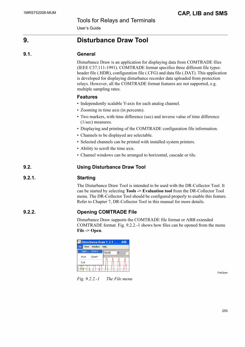
1MRS752008-MUM CAP, LIB and SMS Tools for Relays and TerminalsUser�s Guide
9. Disturbance Draw Tool
9.1. GeneralDisturbance Draw is an application for displaying data from COMTRADE files (IEEE C37.111-1991). COMTRADE format specifies three different file types: header file (.HDR), configuration file (.CFG) and data file (.DAT). This application is developed for displaying disturbance recorder data uploaded from protection relays. However, all the COMTRADE format features are not supported, e.g. multiple sampling rates.
Features� Independently scalable Y-axis for each analog channel.� Zooming in time axis (in percents).� Two markers, with time difference (sec) and inverse value of time difference
(1/sec) measures.� Displaying and printing of the COMTRADE configuration file information.� Channels to be displayed are selectable.� Selected channels can be printed with installed system printers.� Ability to scroll the time axis.� Channel windows can be arranged to horizontal, cascade or tile.
9.2. Using Disturbance Draw Tool
9.2.1. StartingThe Disturbance Draw Tool is intended to be used with the DR-Collector Tool. It can be started by selecting Tools -> Evaluation tool from the DR-Collector Tool menu. The DR-Collector Tool should be configured properly to enable this feature. Refer to Chapter 7, DR-Collector Tool in this manual for more details.
9.2.2. Opening COMTRADE FileDisturbance Draw supports the COMTRADE file format or ABB extended COMTRADE format. Fig. 9.2.2.-1 shows how files can be opened from the menu File -> Open.
FileOpen
Fig. 9.2.2.-1 The File menu
255

1MRS752008-MUM Tools for Relays and TerminalsUser�s Guide
CAP, LIB and SMS
The user can browse a COMTRADE configuration file (.CFG) from the disk with Open dialog. The COMTRADE data file must exist in the same directory as the COMTRADE configuration file. It must also have the same name with the extension .DAT.
9.2.3. Handling channelsThis section deals with changing the scale, zooming, selecting channels, etc.
Fig. 9.2.3.-1 shows the Application window, which presents e.g. the following functions (see the bolded black numbers in the picture):
1. Scrolling the time axis2. Channel scaling3. Scaling of active channel4. Auto-scaling option enabled/disabled for active channel5. Zooming: how many percent from the complete record is displayed.
Fig. 9.2.3.-1 Application window
Changing the scale of Y-axisThe current scale of each analog channel is shown in the title bar of the signal window. The scale can be changed by first activating the channel window. Channel windows can be activated by clicking them with the mouse. The title bar changes its color and the scale value in the toolbar changes to the maximum of the active window scale value. The new maximum scale value can be entered to the scale field in the toolbar. The entered scale value takes effect after the Enter key is pressed. The scale is always ± the scale field value.
256

1MRS752008-MUM CAP, LIB and SMS Tools for Relays and TerminalsUser�s Guide
Zooming in time axisThe mouse can be used for zooming when markers are OFF. If markers are ON, zooming is possible via keyboard with the up/down cursor keys or by changing the value in the zooming field. The user can select how many per cents are to be displayed by changing the value in the zooming field. The user can also select the area to be zoomed in by pressing the left mouse button and holding it down while selecting the area. The size of the currently selected area is shown beside the cursor. Zooming out can be performed by a right mouse click. Zooming with the mouse is possible only when the cursor looks like a magnifier (markers are OFF).
Moving in time axisSignals can be scrolled in the time axis, if the zoom value is smaller than the length of the signal. Fields beside the scroll bar indicate times of the first and the last data sample in a channel window. By clicking these fields, the sample number is shown instead of the time value.
Selecting channels to be displayedFirst, Fig. 9.2.3.-2 shows how to select channels to be displayed from the menu View -> Select channels
Selecting
Fig. 9.2.3.-2 The View menu
Then, the Select Channels dialog appears on the screen (see Fig. 9.2.3.-3). The user can select channels to be displayed from this list by clicking the appropriate channel with the mouse.
257
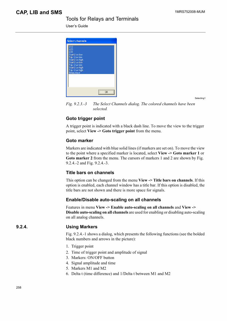
1MRS752008-MUM Tools for Relays and TerminalsUser�s Guide
CAP, LIB and SMS
Selecting1
Fig. 9.2.3.-3 The Select Channels dialog. The colored channels have been selected.
Goto trigger pointA trigger point is indicated with a black dash line. To move the view to the trigger point, select View -> Goto trigger point from the menu.
Goto markerMarkers are indicated with blue solid lines (if markers are set on). To move the view to the point where a specified marker is located, select View -> Goto marker 1 or Goto marker 2 from the menu. The cursors of markers 1 and 2 are shown by Fig. 9.2.4.-2 and Fig. 9.2.4.-3.
Title bars on channelsThis option can be changed from the menu View -> Title bars on channels. If this option is enabled, each channel window has a title bar. If this option is disabled, the title bars are not shown and there is more space for signals.
Enable/Disable auto-scaling on all channelsFeatures in menu View -> Enable auto-scaling on all channels and View -> Disable auto-scaling on all channels are used for enabling or disabling auto-scaling on all analog channels.
9.2.4. Using MarkersFig. 9.2.4.-1 shows a dialog, which presents the following functions (see the bolded black numbers and arrows in the picture):
1. Trigger point2. Time of trigger point and amplitude of signal3. Markers: ON/OFF button4. Signal amplitude and time5. Markers M1 and M26. Delta t (time difference) and 1/Delta t between M1 and M2
258

1MRS752008-MUM CAP, LIB and SMS Tools for Relays and TerminalsUser�s Guide
Fig. 9.2.4.-1 Markers
Markers can be activated by clicking the Markers ON/OFF button in the toolbar. The button text tells whether the markers are enabled (ON) or disabled (OFF). The option to change a marker can be selected from the pop-up menu (click the right mouse button when markers are enabled). An active marker can be moved by holding the left mouse button down while moving the mouse or by using the left/right cursor keys. The cursor shows which marker is currently active (M1 or M2).
Fig. 9.2.4.-2 The cursor of Marker 1
Fig. 9.2.4.-3 The cursor of Marker 2
A marker includes the following data:
� Marker number (M1 or M2)� Sample number� Current value of the signal� Time from the beginning of the record
The calculated time difference and inverse time difference between Marker 1 and 2 are shown in the toolbar on the right hand side of the Markers ON/OFF button.
259
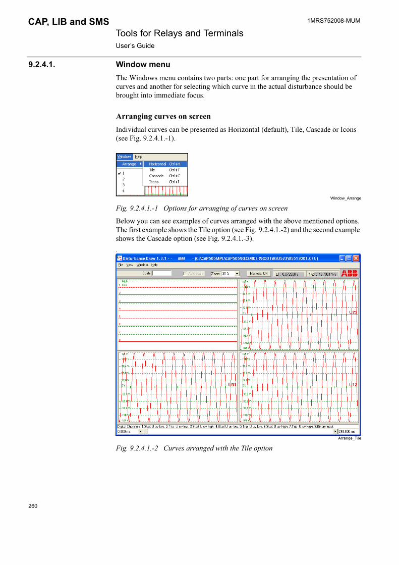
1MRS752008-MUM Tools for Relays and TerminalsUser�s Guide
CAP, LIB and SMS
9.2.4.1. Window menuThe Windows menu contains two parts: one part for arranging the presentation of curves and another for selecting which curve in the actual disturbance should be brought into immediate focus.
Arranging curves on screenIndividual curves can be presented as Horizontal (default), Tile, Cascade or Icons (see Fig. 9.2.4.1.-1).
Window_Arrange
Fig. 9.2.4.1.-1 Options for arranging of curves on screen
Below you can see examples of curves arranged with the above mentioned options. The first example shows the Tile option (see Fig. 9.2.4.1.-2) and the second example shows the Cascade option (see Fig. 9.2.4.1.-3)..
Arrange_Tile
Fig. 9.2.4.1.-2 Curves arranged with the Tile option
260
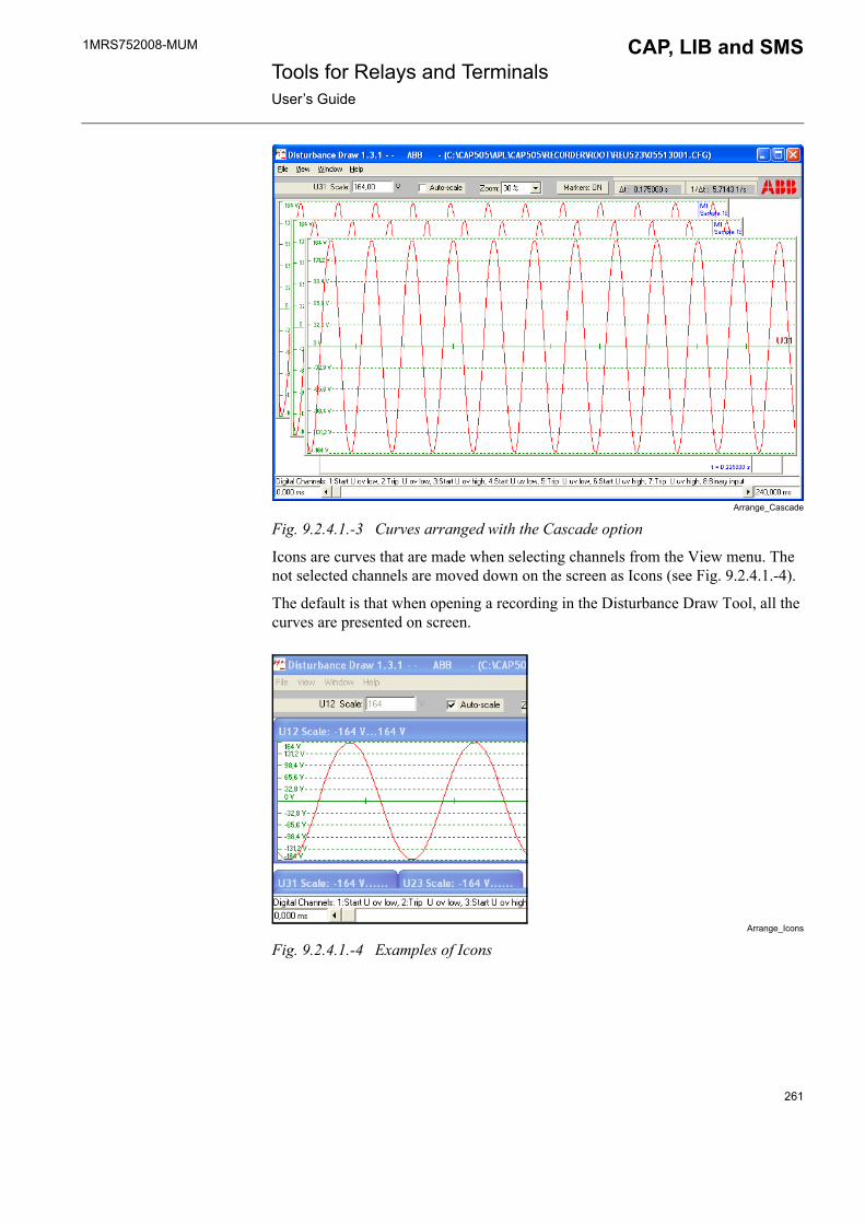
1MRS752008-MUM CAP, LIB and SMS Tools for Relays and TerminalsUser�s Guide
Arrange_Cascade
Fig. 9.2.4.1.-3 Curves arranged with the Cascade option
Icons are curves that are made when selecting channels from the View menu. The not selected channels are moved down on the screen as Icons (see Fig. 9.2.4.1.-4).
The default is that when opening a recording in the Disturbance Draw Tool, all the curves are presented on screen.
Arrange_Icons
Fig. 9.2.4.1.-4 Examples of Icons
261
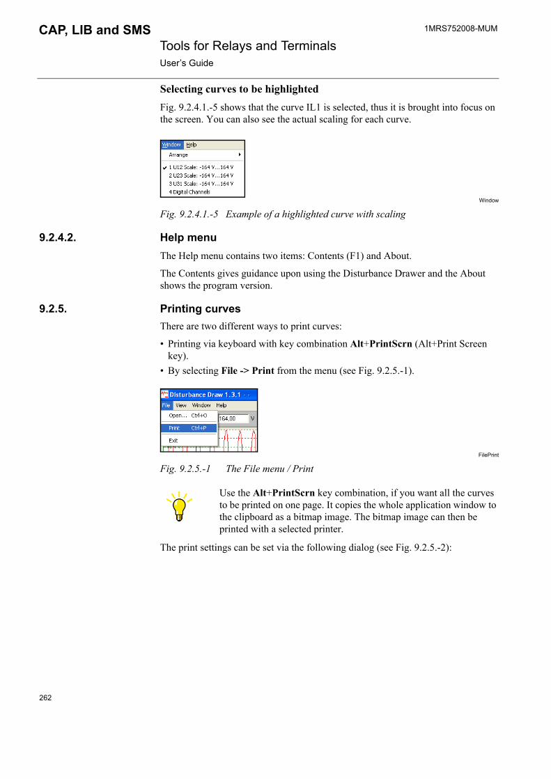
1MRS752008-MUM Tools for Relays and TerminalsUser�s Guide
CAP, LIB and SMS
Selecting curves to be highlightedFig. 9.2.4.1.-5 shows that the curve IL1 is selected, thus it is brought into focus on the screen. You can also see the actual scaling for each curve.
Window
Fig. 9.2.4.1.-5 Example of a highlighted curve with scaling
9.2.4.2. Help menuThe Help menu contains two items: Contents (F1) and About.
The Contents gives guidance upon using the Disturbance Drawer and the About shows the program version.
9.2.5. Printing curvesThere are two different ways to print curves:
� Printing via keyboard with key combination Alt+PrintScrn (Alt+Print Screen key).
� By selecting File -> Print from the menu (see Fig. 9.2.5.-1).
FilePrint
Fig. 9.2.5.-1 The File menu / Print
The print settings can be set via the following dialog (see Fig. 9.2.5.-2):
Use the Alt+PrintScrn key combination, if you want all the curves to be printed on one page. It copies the whole application window to the clipboard as a bitmap image. The bitmap image can then be printed with a selected printer.
262
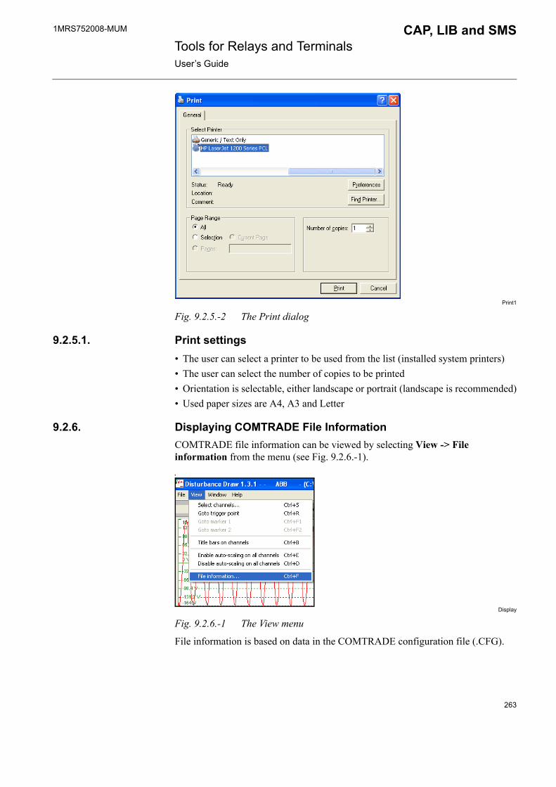
1MRS752008-MUM CAP, LIB and SMS Tools for Relays and TerminalsUser�s Guide
Print1
Fig. 9.2.5.-2 The Print dialog
9.2.5.1. Print settings� The user can select a printer to be used from the list (installed system printers)� The user can select the number of copies to be printed� Orientation is selectable, either landscape or portrait (landscape is recommended)� Used paper sizes are A4, A3 and Letter
9.2.6. Displaying COMTRADE File InformationCOMTRADE file information can be viewed by selecting View -> File information from the menu (see Fig. 9.2.6.-1)..
Display
Fig. 9.2.6.-1 The View menu
File information is based on data in the COMTRADE configuration file (.CFG).
263
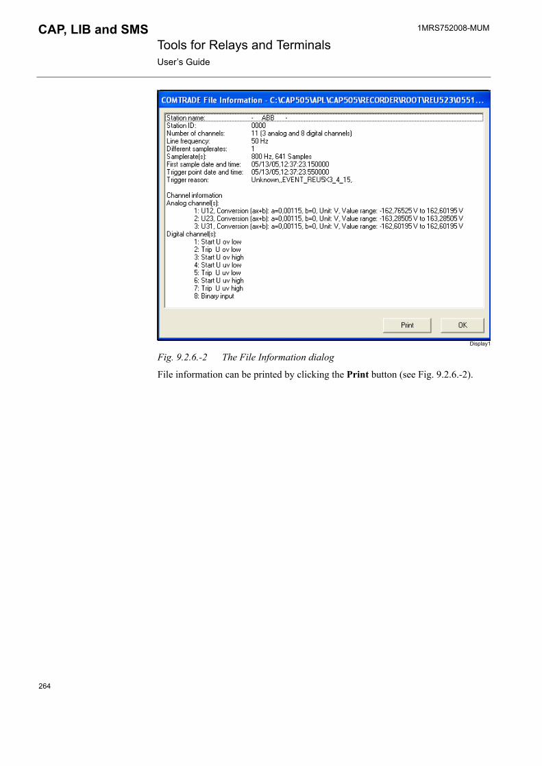
1MRS752008-MUM Tools for Relays and TerminalsUser�s Guide
CAP, LIB and SMS
Display1
Fig. 9.2.6.-2 The File Information dialog
File information can be printed by clicking the Print button (see Fig. 9.2.6.-2).
264

1MRS752008-MUM CAP, LIB and SMS Tools for Relays and TerminalsUser�s Guide
10. Power Quality Monitoring Tool
10.1. GeneralThe Power Quality Monitoring Tool is used to visualize the data generated by PQ IEDs (Power Quality Intelligent Electronic Devices) and uploaded by MicroSCADA. This tool is only available in LIB 510/MicroSCADA.
10.2. Start-upStart by clicking the relay unit�s push-button in the station picture. Select the PQ-Monitoring Tool from the opened dialog and click Run.
pqm_o_tool
Fig. 10.2.-1 Tool Menu for a relay unit object
If the selected relay unit does not have any PQ-Monitoring Function, the Monitoring Tool will not open and the following dialog will appear on the screen.
ErrorDlg
Fig. 10.2.-2 A dialog indicating that PQ function is not available
265
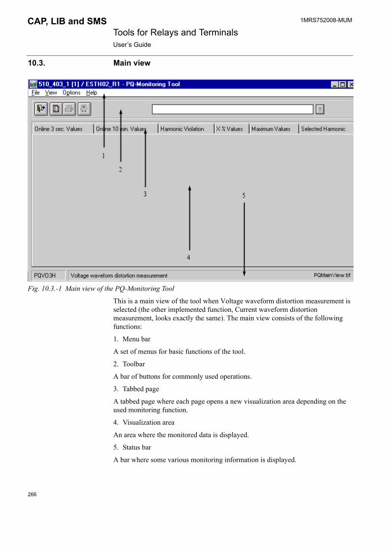
1MRS752008-MUM Tools for Relays and TerminalsUser�s Guide
CAP, LIB and SMS
10.3. Main view
Fig. 10.3.-1 Main view of the PQ-Monitoring Tool
This is a main view of the tool when Voltage waveform distortion measurement is selected (the other implemented function, Current waveform distortion measurement, looks exactly the same). The main view consists of the following functions:
1. Menu bar
A set of menus for basic functions of the tool.
2. Toolbar
A bar of buttons for commonly used operations.
3. Tabbed page
A tabbed page where each page opens a new visualization area depending on the used monitoring function.
4. Visualization area
An area where the monitored data is displayed.
5. Status bar
A bar where some various monitoring information is displayed.
266
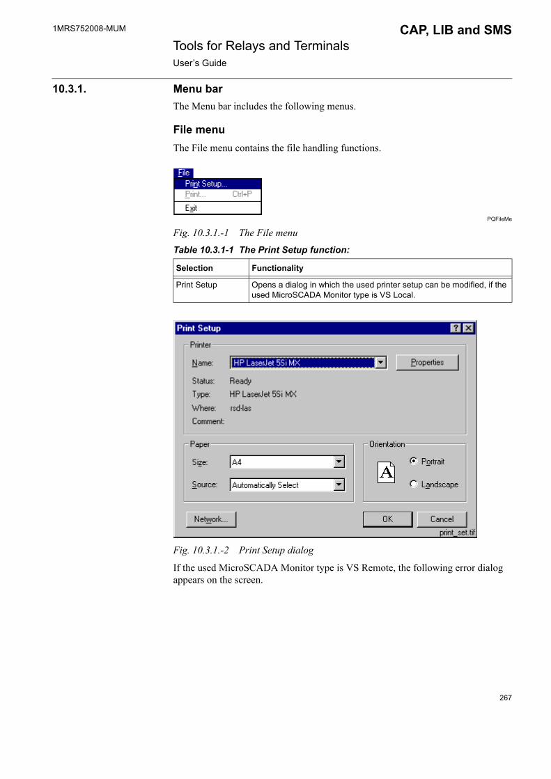
1MRS752008-MUM CAP, LIB and SMS Tools for Relays and TerminalsUser�s Guide
10.3.1. Menu barThe Menu bar includes the following menus.
File menuThe File menu contains the file handling functions.
PQFileMe
Fig. 10.3.1.-1 The File menu
Table 10.3.1-1 The Print Setup function:
Fig. 10.3.1.-2 Print Setup dialog
If the used MicroSCADA Monitor type is VS Remote, the following error dialog appears on the screen.
Selection Functionality
Print Setup Opens a dialog in which the used printer setup can be modified, if the used MicroSCADA Monitor type is VS Local.
267

1MRS752008-MUM Tools for Relays and TerminalsUser�s Guide
CAP, LIB and SMS
Fig. 10.3.1.-3 Print Setup error dialog
When the VS Remote monitor is used, the printer selection must be done when starting the MicroSCADA monitor.
VSPrinter
Fig. 10.3.1.-4 VS Printer selection in MicroSCADA VS Remote Monitor start-up
Table 10.3.1-2 The Print function:
Selection Functionality
Print Opens a printing dialog of the current page where the setup can also be changed (VS Local Monitor type). If the used Monitor type is VS Remote, the Print dialog is another.
268

1MRS752008-MUM CAP, LIB and SMS Tools for Relays and TerminalsUser�s Guide
Fig. 10.3.1.-5 Print dialog on a VS Local Monitor
Fig. 10.3.1.-6 The Print dialog on a VS Remote Monitor
Fig. 10.3.1.-7 Error dialog when the Active Menu file was not found
Printing needs information from the active menu of the used relay. If the active menu file of the relay is not found, an error dialog pops up (see Fig. 10.3.1.-7) and the menu should be build with the Relay Setting Tool.
269
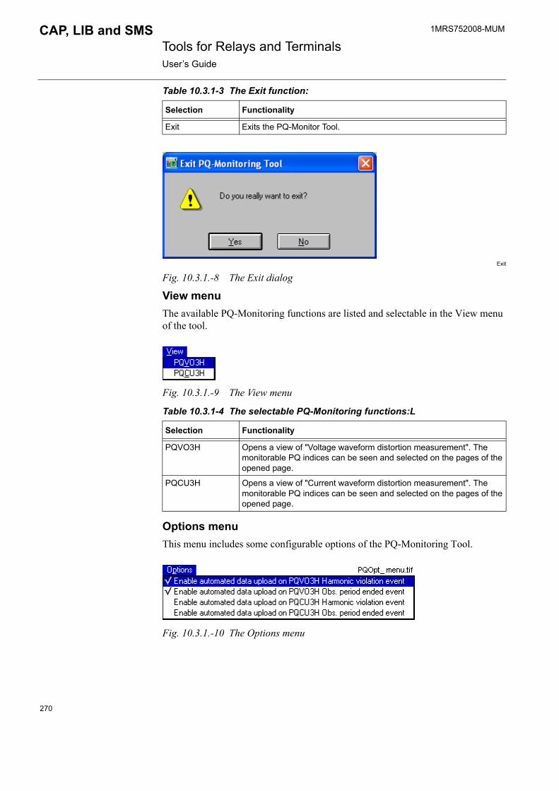
1MRS752008-MUM Tools for Relays and TerminalsUser�s Guide
CAP, LIB and SMS
Table 10.3.1-3 The Exit function:
Exit
Fig. 10.3.1.-8 The Exit dialog
View menuThe available PQ-Monitoring functions are listed and selectable in the View menu of the tool.
Fig. 10.3.1.-9 The View menu
Table 10.3.1-4 The selectable PQ-Monitoring functions:L
Options menuThis menu includes some configurable options of the PQ-Monitoring Tool.
Fig. 10.3.1.-10 The Options menu
Selection Functionality
Exit Exits the PQ-Monitor Tool.
Selection Functionality
PQVO3H Opens a view of "Voltage waveform distortion measurement". The monitorable PQ indices can be seen and selected on the pages of the opened page.
PQCU3H Opens a view of "Current waveform distortion measurement". The monitorable PQ indices can be seen and selected on the pages of the opened page.
270
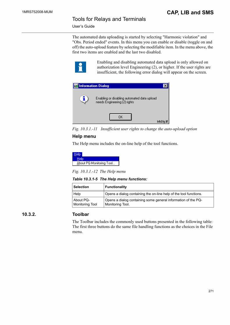
1MRS752008-MUM CAP, LIB and SMS Tools for Relays and TerminalsUser�s Guide
The automated data uploading is started by selecting "Harmonic violation" and "Obs. Period ended" events. In this menu you can enable or disable (toggle on and off) the auto-upload feature by selecting the modifiable item. In the menu above, the first two items are enabled and the last two disabled.
Fig. 10.3.1.-11 Insufficient user rights to change the auto-upload option
Help menuThe Help menu includes the on-line help of the tool functions.
Fig. 10.3.1.-12 The Help menu
Table 10.3.1-5 The Help menu functions:
10.3.2. ToolbarThe Toolbar includes the commonly used buttons presented in the following table: The first three buttons do the same file handling functions as the choices in the File menu.
Enabling and disabling automated data upload is only allowed on authorization level Engineering (2), or higher. If the user rights are insufficient, the following error dialog will appear on the screen.
Selection Functionality
Help Opens a dialog containing the on-line help of the tool functions.
About PQ-Monitoring Tool
Opens a dialog containing some general information of the PQ-Monitoring Tool.
271

1MRS752008-MUM Tools for Relays and TerminalsUser�s Guide
CAP, LIB and SMS
Table 10.3.2-1 Commonly used buttons in the toolbar:
Some further information is also viewed on the toolbar. The presented information depends on what is being monitored. If the on-line values are viewed, the information of "Measured input" is shown. In the case of harmonic violation the "Violation Period" is shown and can be selected from the toolbar. If the values from a certain period are monitored, the "Observation Period" is shown and selectable on the toolbar.
Fig. 10.3.2.-1 Information of the selected Harmonic Violation Period
10.3.3. Tabbed pageA tabbed page is opened, when you make a selection of the monitoring function (Voltage or Current waveform distortion measurement) from the View menu. When you click the wanted page, the actual page opens for visualization.
MoniData
Fig. 10.3.3.-1 The list of monitored data on Voltage or Current Harmonics
If there is no saved data for a Harmonic Violation Period or an Observation Period the following information dialog appears on the screen.
InfoDlg2
Fig. 10.3.3.-2 An information dialog of saved data not available
Button Functionality
Exit
Print Setup
Upload button used to upload on-line data from the relay
272

1MRS752008-MUM CAP, LIB and SMS Tools for Relays and TerminalsUser�s Guide
10.3.4. Visualization areaThis is the area where the actual results are being visualized. The uploaded or saved data is shown on a bar chart of harmonics or on a cumulative curve of the selected harmonic.
The bar chart of a Harmonic Violation Period consists of bars and a curve.
Fig. 10.3.4.-1 A bar chart of a Selected Harmonic Violation Period
In this picture, the height of each bar describes the magnitude of a harmonic value. The values under the adjustable limits (yellow lines) are shown with green bars and the values over the limits with red bars. The continuous black curve describes the limits of the EN 50160 Standard for each harmonic.
273

1MRS752008-MUM Tools for Relays and TerminalsUser�s Guide
CAP, LIB and SMS
A picture of a Selected Harmonic during a selected Observation Period is shown in the following figure (see Fig. 10.3.4.-2).
Fig. 10.3.4.-2 A cumulative curve of selected harmonic during an Observation Period (Requirements fulfilled)
This curve is drawn according to five percentiles (1%, 5%, 50%, 95% and 99%) calculated by the relay unit. The adjusted limit value for a selected harmonic is shown with a red horizontal line. If the 95% percentile value for the selected harmonic is under the adjusted limit, the cumulative curve is blue and the requirements are fulfilled.
If the 95% percentile value for the selected harmonic exceeds the adjusted limit, the cumulative curve changes to red and the requirements are not fulfilled.
274
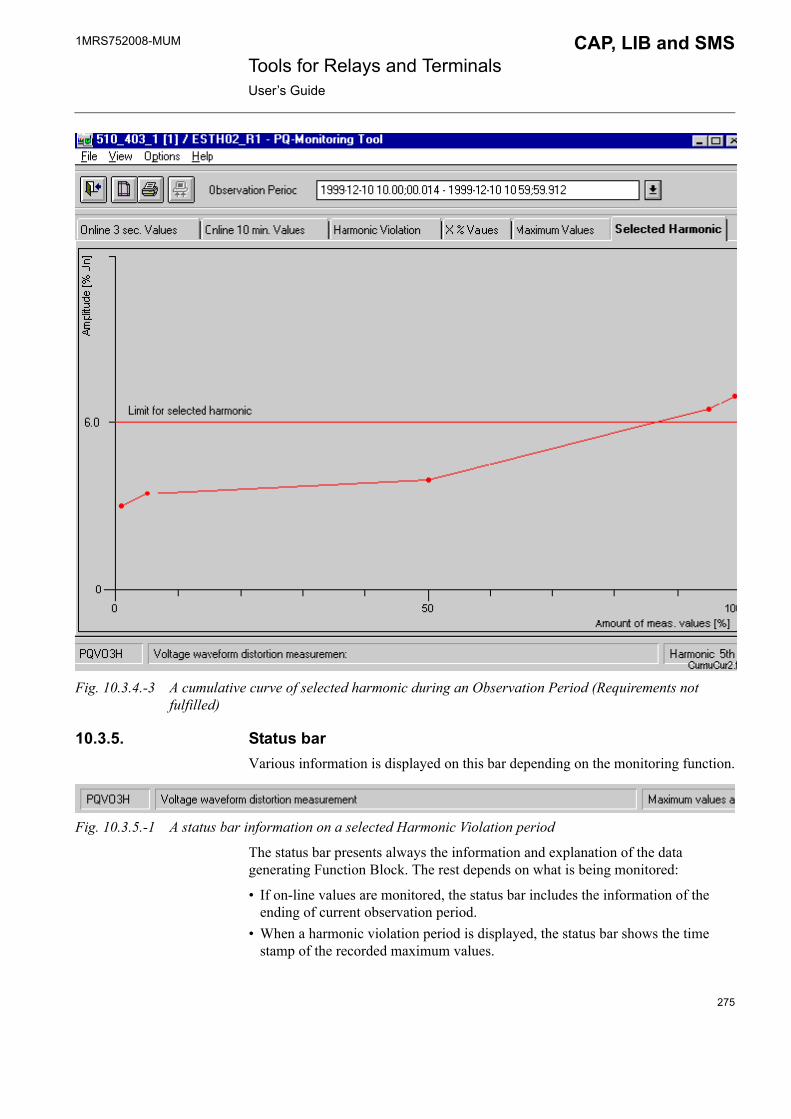
1MRS752008-MUM CAP, LIB and SMS Tools for Relays and TerminalsUser�s Guide
Fig. 10.3.4.-3 A cumulative curve of selected harmonic during an Observation Period (Requirements not fulfilled)
10.3.5. Status barVarious information is displayed on this bar depending on the monitoring function.
Fig. 10.3.5.-1 A status bar information on a selected Harmonic Violation period
The status bar presents always the information and explanation of the data generating Function Block. The rest depends on what is being monitored:
� If on-line values are monitored, the status bar includes the information of the ending of current observation period.
� When a harmonic violation period is displayed, the status bar shows the time stamp of the recorded maximum values.
275

1MRS752008-MUM Tools for Relays and TerminalsUser�s Guide
CAP, LIB and SMS
� If the X% values are monitored, the adjusted X (percentile) is shown.
A number of the harmonic (or THD) is viewed, when the curve of selected harmonic is presented.
10.4. Monitoring functionalityAfter the PQ-Monitoring Tool has been started, you should select the wanted monitoring function from the View menu. By selecting the first or second page from the opened page (On-line 3 sec. Values and On-line 10 min. Values), the on-line values from the relay can be uploaded. The on-line mode is also indicated by the upload button.
The rest of the pages are used for saved data visualization. When any of these tabbed pages is selected, the upload button is disabled.
10.4.1. On-line monitoringThe on-line monitoring is started by pressing the upload button on the toolbar. When the uploading begins, the following indicator of the process proceeding pops up.
Fig. 10.4.1.-1 An indication dialog of the uploading process proceeding
If the relay unit does not answer or there is some other communication problem, an error dialog appears on the screen (see Fig. 10.4.1.-2)
ErrorDlg4
Fig. 10.4.1.-2 An error dialog of communication problem
The manual data uploading requires authorization level Control (1) or higher. Otherwise, the following information dialog is opened (see Fig. 10.4.1.-3).
276

1MRS752008-MUM CAP, LIB and SMS Tools for Relays and TerminalsUser�s Guide
Fig. 10.4.1.-3 Insufficient user rights to manual data uploading
10.4.2. Monitoring of saved dataTo monitor the previously saved data, select the wanted time period from the drop-down list on the toolbar.
Fig. 10.4.2.-1 Selection of a harmonic violation period from a drop-down list
When you have selected a period, the progress indicator opens and the saved data is read from the disk. After that, the results are ready to be visualized.
277

278

1MRS752008-MUM CAP, LIB and SMS Tools for Relays and TerminalsUser�s Guide
11. Event Log Viewer
11.1. GeneralThe Event Log Viewer is a tool for uploading and viewing of event logs uploaded from RED 500 platform relays. The tool is used for the following purposes:
� Uploading new event logs from the connected relay� Viewing uploaded event logs� Saving uploaded event logs� Opening saved event logs� Exporting event logs to a text file� Printing event logs
The purpose of the Event Log Viewer is to provide means to get a snapshot of the current events in the event view of the relay. The events and their order in the file is the same as in the event view seen on the HMI of the relay. The contents of the uploaded log can be considered to be like history events.
The Event Log Viewer is used in CAP 501, CAP 505 and SMS 510 environments. It is available only for certain RED 500 platform relays supporting this feature. The first relay types having this support are REF 54x rel. 3.0 and REX 521 rev. E. REF 543 relay has been used here as an example for capturing figures.
11.2. Start-upThe Event Log Viewer tool is started from the Project Structure Navigator. Before starting the tool, the desired relay object should be selected in the project structure tree.
The tools that are available for the selected object appear on the Object Tools list, as shown in Fig. 11.2.-1. By default, the Event Log Viewer is not available as an object tool in the Project Structure Navigator for a newly created relay object, since it is available only for certain relay types and revisions. To be able to use the tool, the relay object has to be configured so that the selected configuration supports event log uploading.
The Event Log Viewer tool can be opened by double-clicking its name on the list.
279

1MRS752008-MUM Tools for Relays and TerminalsUser�s Guide
CAP, LIB and SMS
Fig. 11.2.-1 Starting the Event Log Viewer tool from the Project Structure Navigator.
11.3. User interfaceThe main view of the Event Log Viewer is shown in Fig. 11.3.-1.
ELV_main
Fig. 11.3.-1 The main view of the Event Log Viewer
280
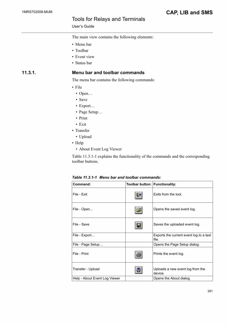
1MRS752008-MUM CAP, LIB and SMS Tools for Relays and TerminalsUser�s Guide
The main view contains the following elements:
� Menu bar� Toolbar� Event view� Status bar
11.3.1. Menu bar and toolbar commandsThe menu bar contains the following commands:
� File� Open� � Save� Export�� Page Setup�� Print� Exit
� Transfer� Upload
� Help� About Event Log Viewer
Table 11.3.1-1 explains the functionality of the commands and the corresponding toolbar buttons.
Table 11.3.1-1 Menu bar and toolbar commands:
Command: Toolbar button: Functionality:
File - Exit Exits from the tool.
File - Open... Opens the saved event log.
File - Save Saves the uploaded event log.
File - Export� Exports the current event log to a text file.
File - Page Setup� Opens the Page Setup dialog.
File - Print Prints the event log.
Transfer - Upload Uploads a new event log from the device.
Help - About Event Log Viewer Opens the About dialog.
281

1MRS752008-MUM Tools for Relays and TerminalsUser�s Guide
CAP, LIB and SMS
Event viewThe event view contains the events uploaded from the relay as such. This means that the events, their order and the time stamps are exactly what they were when written into the event view of the relay. Due to this fact, it should be noticed that the time stamps may not always be in the time order. This is because the real-time clock of the relay may have been set to any time, depending of the existence or non-existence of the time-synchronization.
The columns of the event view are described in Table 11.3.-1..
Status barWhen an event log is shown, the status bar contains the following information about the log:
� Relay product definition, revision and build number taken from the event log file header. For example, "REF543 /H 4.18" for a REF 54x or "REX521 /H02 E 4.03.00" for a REX 52x.
� Date and time stamp of the event log file generation.
11.4. Using the Event Log Viewer
11.4.1. Uploading an event logA new uploading of an event log file is started by selecting Transfer - Upload from the menu or by clicking the corresponding toolbar button. If the uploading process is started successfully, a progress window will be shown during the uploading (see Fig. 11.4.1.-1).
Table 11.3.-1 Event view columns:
Column: Description:# Order number of the event in the file.Time Event registration time stamped by the relay.Description Fixed part of the text corresponding to the event
code and the function block.State Dynamic part of the text corresponding to the event
code and the function block.FB/Rev. Function block name and revision corresponding to
the channel producing the event.Code/Ch Event code and channel number producing the
event.
282

1MRS752008-MUM CAP, LIB and SMS Tools for Relays and TerminalsUser�s Guide
Fig. 11.4.1.-1 Uploading progress window
After the uploading has been finished successfully, the new event log will be shown in the main view (see Fig. 11.3.-1).
11.4.1.1. Communication problemsCommunication problems may occur when initializing the communication or during the communication process. A proper error dialog will be shown in these cases. A couple of examples are described below:
If, for some reason, there is a mismatch between the object settings and the connected relay (and the connected relay does not support event log uploading), the following dialog may be shown for a long time before another error message will be shown.
Fig. 11.4.1.1.-1 Checking event log support
If the communication settings of the object are invalid, then an error dialog will be shown (see Fig. 11.4.1.1.-2). Improper address settings can be the reason for this.
283

1MRS752008-MUM Tools for Relays and TerminalsUser�s Guide
CAP, LIB and SMS
Fig. 11.4.1.1.-2 Error dialog for invalid communication settings
11.4.2. Saving an event logThe uploaded event log can be saved to a disk. To save the event log, select File - Save from the menu or click the corresponding toolbar button.
The file is saved with an automatically generated name to a fixed location, so no additional questions are asked when the saving is done. The name consists of the time stamp of the uploaded log, and the location is a dedicated folder under the current object folder in the CAP 505/SMS 510 project.
Due to the reasons stated above, each uploaded log can be saved only once.
11.4.3. Opening a saved event logA saved event log can be opened any time by selecting File - Open� from the menu or by clicking the corresponding toolbar button. By doing this, the Event Logs dialog will be opened (see Fig. 11.4.3.-1).
Fig. 11.4.3.-1 Event Logs dialog
284

1MRS752008-MUM CAP, LIB and SMS Tools for Relays and TerminalsUser�s Guide
The Event Logs dialog contains a list of the previously saved logs. Each log is identified with the same information (i.e. relay product and time stamp), which was visible on the status bar after uploading from the relay.
To open an existing event log, select a row on the list and click the Open button. To delete an event log, select a row on the list and click the Delete button.
11.4.4. Exporting an event log into a text fileThe File - Export� menu command is used to export the current event log file into a text file. To start the operation, select the menu command and the file selection dialog appears on the screen.
export_event_log
Fig. 11.4.4.-1 Export Event Log dialog
To complete the export operation, type a file name or select an existing file and click the OK button. Overwriting an existing file is confirmed.
The export file contains a few header rows and the actual event rows exactly as shown on the event view list. The header rows begin with a "#" character and the columns in the event rows are separated with tabulator characters.
The difference between saving and exporting is that the export format contains also descriptive texts, and the exporting can be done to any location with any valid file name.
285

1MRS752008-MUM Tools for Relays and TerminalsUser�s Guide
CAP, LIB and SMS
11.4.5. Printing an event logThe current event log can be printed to any printer defined in the operating system. After selecting File - Print from the menu or by clicking the corresponding toolbar button, the standard Print dialog of the operating system appears on the screen. Any available printer can be selected and the printer settings can be configured as needed before the printing.
The margins of the page layout can be configured before printing. By using the File - Page Setup� menu command, the margins can be specified on the Page Setup dialog (see Fig. 11.4.5.-1).
Fig. 11.4.5.-1 Page Setup dialog
286

1MRS752008-MUM CAP, LIB and SMS Tools for Relays and TerminalsUser�s Guide
12. REx 61x DNP 3.0 point configuration
12.1. GeneralThe objective of the DNP object editing is to create a customized DNP object interface for REx 61x relays. This configuration dialog is an extension to the RED Relay Setting Tool. Editing features include removing, adding, remapping and reorganization of DNP points.
The dialog is divided into tabs by the DNP object type:
� Binary points handle DNP object groups 1 and 2� Analog points handle object groups 30 and 32� Counter points handle object groups 20, 21 and 22
Please note that the DNP protocol's communication line parameters and profile parameters can be found in separate tabs in the Relay Setting Tool (see Fig. 12.1.-1).
DNP_parameters
Fig. 12.1.-1 The DNP parameters of the Relay Setting Tool
12.2. Start-upDNP 3.0 point configuration is available in CAP 501/505 and SMS 510. The configuration dialog is started from the RED Relay Setting Tool.
All the DNP parameters (also the line parameters and profile parameters) are stored on an external DNP module in the relay. If DNP parameters have been altered, it is necessary to switch the relay back to the rear communication mode for at least 10 seconds in order for the DNP parameters to be replicated and stored on the DNP module.
287

1MRS752008-MUM Tools for Relays and TerminalsUser�s Guide
CAP, LIB and SMS
12.3. Using the DNP 3.0 point configuration dialog
12.3.1. Entering the DNP point editing dialogYou can enter the DNP point editing dialog from any of the three DNP parameter tabs. You can do this by setting the cursor to the New Value field and by pressing any key. The DNP configuration dialog will then open with detailed information about the DNP objects in question (see Fig. 12.3.1.-1).
DNP point editing dialog
Fig. 12.3.1.-1 Entering the DNP point dialog
12.3.2. Editing DNP points
12.3.2.1. Editing in generalThis section applies to all DNP parameter tabs (Binary points, Analog points and Counter points).
288
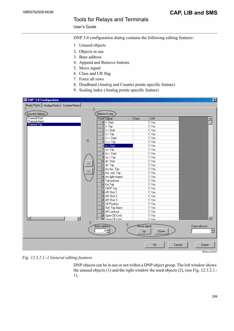
1MRS752008-MUM CAP, LIB and SMS Tools for Relays and TerminalsUser�s Guide
DNP 3.0 configuration dialog contains the following editing features:
1. Unused objects2. Objects in use 3. Base address4. Append and Remove buttons5. Move signal6. Class and UR flag7. Force all rows8. Deadband (Analog and Counter points specific feature)9. Scaling index (Analog points specific feature)
Binary points1
Fig. 12.3.2.1.-1 General editing features
DNP objects can be in use or not within a DNP object group. The left window shows the unused objects (1) and the right window the used objects (2), (see Fig. 12.3.2.1.-1).
289
1MRS752008-MUM Tools for Relays and TerminalsUser�s Guide
CAP, LIB and SMS
Objects located in the �Objects in use� window are automatically sorted in a contiguous addressing order within the DNP object group in question. It is possible to affect only the Base address (3) of the points within the object group. If the base address is changed, the addresses of all the following DNP points will be changed accordingly.
Objects can be taken into use or out of use by moving them between the �Objects in use� and �Unused Objects� windows by selecting them and clicking the Append >> or Remove << button (4). Note that it is possible to select several objects at a time.
Objects which are moved to the �Objects in use� window are always appended to the end of the current point list. It is possible to remap the order of these objects by selecting an object to be moved and then clicking the Up and Down buttons (5).
To select several objects you can:
- Press Ctrl and paint all the objects to be moved- Click the right mouse-button and choose Select All- Click Point in the �Objects in use� window
290
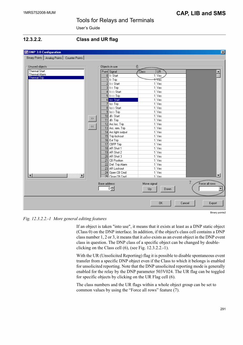
1MRS752008-MUM CAP, LIB and SMS Tools for Relays and TerminalsUser�s Guide
12.3.2.2. Class and UR flag
Binary points2
Fig. 12.3.2.2.-1 More general editing features
If an object is taken "into use", it means that it exists at least as a DNP static object (Class 0) on the DNP interface. In addition, if the object's class cell contains a DNP class number 1, 2 or 3, it means that it also exists as an event object in the DNP event class in question. The DNP class of a specific object can be changed by double-clicking on the Class cell (6), (see Fig. 12.3.2.2.-1).
With the UR (Unsolicited Reporting) flag it is possible to disable spontaneous event transfer from a specific DNP object even if the Class to which it belongs is enabled for unsolicited reporting. Note that the DNP unsolicited reporting mode is generally enabled for the relay by the DNP parameter 503V024. The UR flag can be toggled for specific objects by clicking on the UR Flag cell (6).
The class numbers and the UR flags within a whole object group can be set to common values by using the �Force all rows� feature (7).
291

1MRS752008-MUM Tools for Relays and TerminalsUser�s Guide
CAP, LIB and SMS
12.3.2.3. Additional columns for analog points
Analog points
Fig. 12.3.2.3.-1 Additional editing features for analog points
DeadbandIf event transfer is defined for an analog object, it is necessary to define a deadband value for the event reporting. The deadband value is always defined in units of the original DNP analog value (Not in units of the scaled analog value, if scaling is in use. See the next section). The Deadband range is 0-255. The original DNP value representations for analog objects are listed in the relay's Technical Reference Manual.
Scaling index The user can exchange the original (internal) DNP value scaling factor with an own definition. It is possible to define up to 5 scaling factors in the DNP Profile parameters tab. The scaling of a DNP analog object should then be configured with a scaling index to the scaling factor (F503V101...105) in question. If the scaling index is set to 0 or outside the range (1-5), it means that the original (internal) scaling factor is used for the object in question.
12.3.2.4. Additional columns for counter points
Counter points
Fig. 12.3.2.4.-1 Additional editing feature for counter points
DeadbandThis column defines deadband (in this case counts) for the counter objects� event transfer. The Deadband range is 0-255.
292
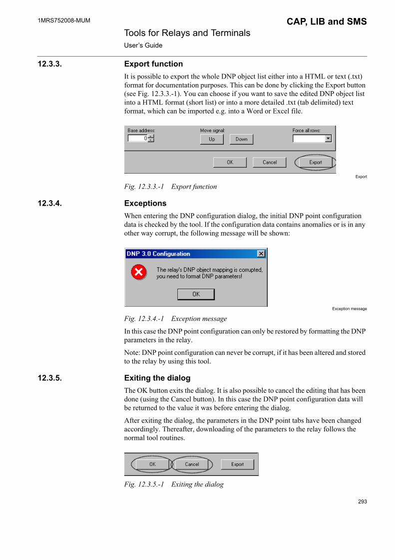
1MRS752008-MUM CAP, LIB and SMS Tools for Relays and TerminalsUser�s Guide
12.3.3. Export functionIt is possible to export the whole DNP object list either into a HTML or text (.txt) format for documentation purposes. This can be done by clicking the Export button (see Fig. 12.3.3.-1). You can choose if you want to save the edited DNP object list into a HTML format (short list) or into a more detailed .txt (tab delimited) text format, which can be imported e.g. into a Word or Excel file.
Export
Fig. 12.3.3.-1 Export function
12.3.4. ExceptionsWhen entering the DNP configuration dialog, the initial DNP point configuration data is checked by the tool. If the configuration data contains anomalies or is in any other way corrupt, the following message will be shown:
Exception message
Fig. 12.3.4.-1 Exception message
In this case the DNP point configuration can only be restored by formatting the DNP parameters in the relay.
Note: DNP point configuration can never be corrupt, if it has been altered and stored to the relay by using this tool.
12.3.5. Exiting the dialogThe OK button exits the dialog. It is also possible to cancel the editing that has been done (using the Cancel button). In this case the DNP point configuration data will be returned to the value it was before entering the dialog.
After exiting the dialog, the parameters in the DNP point tabs have been changed accordingly. Thereafter, downloading of the parameters to the relay follows the normal tool routines.
Fig. 12.3.5.-1 Exiting the dialog
293

294
1MRS752008-MUM CAP, LIB and SMS Tools for Relays and TerminalsUser�s Guide
13. Troubleshooting
This chapter provides information that aims to help your recovering from problems that you may have encountered during the usage of relay and terminal tools.
13.1. Windows Installer appears when a program is startedIf you have the Microsoft Office installed, but have never started any Office program as the same logon user you are currently running CAP, SMS or LIB, the following happens: when you start the DNP 3.0 configuration dialog from the RED Relay Setting Tool (or any other Visual BASIC application), the Windows Installer appears:
DNP 3.0 Configuration Setup1
Fig. 13.1.-1 Windows Installer appears
After that the Microsoft Office setup begins and goes forward depending on the currently installed version. The following dialogs might be shown:
DNP 3.0 Configuration Setup2
Fig. 13.1.-2 Microsoft Office setup begins
295

1MRS752008-MUM Tools for Relays and TerminalsUser�s Guide
CAP, LIB and SMS
DNP 3.0 Configuration Setup3
Fig. 13.1.-3 Microsoft Office setup goes forward
The need to run an initial setup for every user is a Microsoft Office feature. This can be solved by first cancelling the Microsoft Installer, and then just starting and closing Microsoft Word. That should prepare the current user for the Microsoft Office, and the CAP/SMS/LIB tool you tried to run should now start without problems.
13.2. Incorrect printoutsPrinting from Visual SCIL based tools sometimes produces incorrect printouts. Black stripes may be added to the printout, or some images or texts are not printed at all.
Incorrect printouts are due to the "metafile spooling" option used in the current printer driver. This option should be disabled in the printer properties dialog. Different printer drivers may use different names for this "metafile spooling" feature; e.g. the term "advanced printer features" is used by some Hewlett-Packard drivers.
296
1MRS752008-MUM CAP, LIB and SMS Tools for Relays and TerminalsUser�s Guide
14. Index
Symbols# of Recordings ....................................................................................... 235.CFG ....................................................................................................... 218.DAT ....................................................................................................... 218? .............................................................................................. 155, 156, 157
AAbout Setting Tool ................................................................................. 197Active Menu File .................................................................................... 170Active setting group ............................................................................... 165Add ......................................................................................................... 196Add-on protocols ...................................................................................... 27Alarm LED signals ................................................................................. 199Alarm reporting ........................................................................................ 57All view .................................................................................................. 181Apl library list ..................................................................................... 29, 31Application library management functions .............................................. 30Attributes .................................................................................................. 76Attributes folder .................................................................................. 20, 75Authorization group .................................................................................. 77Automated upload .................................................................. 231, 232, 247Automated upload in progress ................................................................ 229Automated upload in stand-by ................................................................ 228Automated upload not in use .................................................................. 227Automated upload temporarily not in use .............................................. 228Automatic updating ................................................................................ 168
BBase system objects .................................................................................. 20Bind to Configurations ........................................................................... 194Build Active Menu File .................................................................. 171, 190
CCancellation ............................................................................................ 152Changing address ............................................................................ 249, 251Changing the scale of Y-axis .................................................................. 256Channel ..................................................................................................... 57COM 610 communication gateway .................................................... 55, 84Commands .............................................................................................. 149Communication menu ............................................................................ 160Communication priority ......................................................................... 232Communication settings ........................................................................... 55Compare ......................................................................................... 162, 186Compare New Values dialog .................................................................. 188
297
1MRS752008-MUM Tools for Relays and TerminalsUser�s Guide
CAP, LIB and SMS
COMTRADE ......................................................................................... 255Configuration
Apl ...................................................................................................... 34Mismatch message ............................................................................. 35SW ...................................................................................................... 34
Copy ....................................................................................................... 219Create Directories ................................................................................... 223Creating a new configuration ................................................................. 192Currents (I, I0) .......................................................................................... 81Cycle ...................................................................................................... 231
DDatabase name ........................................................................................ 186Date of recording .................................................................................... 217DD .......................................................................................................... 218Default path ............................................................................................ 223Delete ..................................................................................................... 219Delete Recording .................................................................................... 244Directory structure .................................................................................. 221Disable automated upload until this session ended ................................ 228Displaying COMTRADE File Information ........................................... 263Disturbance Draw Tool .......................................................................... 255Disturbance Recorder module/function block ........................................ 216Disturbance recording file ...................................................................... 226Disturbance recording format ................................................................. 222Do not open this dialog automatically during this session ..................... 229Download ............................................................................................... 183Download parameters ............................................. 161, 173, 183, 198, 201DR-Collector Tool ........................................................................... 17, 255Drive ............................................................................................... 223, 227Drive name ..................................................................................... 219, 227
EEnable/Disable auto-scaling ................................................................... 258Error codes ............................................................................................. 231Error dialog ............................................................................................ 183Ethernet adapter SPA-ZC 400/402 ........................................................... 55Event Editor ........................................................................................... 231Event List ............................................................................................... 231Event Log Viewer .................................................................................. 279Event mask ............................................................................................. 232Event notification ................................................................................... 230Event notification group box .................................................................. 232Event process objects of RED relay units ................................................ 57Event reporting ......................................................................................... 57Exit ......................................................................................... 154, 180, 270
298
1MRS752008-MUM CAP, LIB and SMS Tools for Relays and TerminalsUser�s Guide
Export ............................................................................................. 150, 175Export parameters ........................................................................... 173, 200EXT ........................................................................................................ 218Extension ................................................................................................ 235
FF .............................................................................................................. 251Features ................................................................................................... 255File handling ........................................................................................... 149File Value ....................................................................................... 186, 187Function blocks .................................................................................. 25, 57Function groups ...................................................................................... 157
GGeneral page ........................................................................................... 232Goto marker ............................................................................................ 258Goto trigger point ................................................................................... 258Graphical I/O Setting Tool ..................................................................... 199
Alarm LED Matrix ........................................................................... 206Input Matrix ...................................................................................... 203Matrix pages ..................................................................................... 201Output Matrix ................................................................................... 204Starting from CAP 501/505 or SMS 510 ......................................... 199
HHandling Channels ................................................................................. 256Harmonic violation ................................................................................. 271Harmonic Violation Period ..................................................... 272, 273, 275HDR ........................................................................................................ 224Help menu .............................................................................................. 166HMI ........................................................................................................ 170Home root directory ................................................................................. 24Host type ................................................................................................... 55
IIdentification ........................................................................................... 235IEC/ANSI terminology ....................................................................... 48, 50Import ............................................................................................. 149, 175Import parameters ........................................................................... 173, 200Importing ................................................................................................ 149In Use ...................................................................................................... 231Input values ............................................................................ 36, 37, 43, 44Ip ............................................................................................................... 81Ir ............................................................................................................... 81Is ............................................................................................................... 81
299

1MRS752008-MUM Tools for Relays and TerminalsUser�s Guide
CAP, LIB and SMS
KKU-2000 gateway ...................................................................... 17, 56, 215
LLanguage dependent text files .................................................................. 85LIB_OBJECT_NAME ............................................................................. 77Line number ........................................................................................... 217Local printer ................................................................... 153, 154, 179, 180Location .................................................................................. 218, 220, 234Logical names (LN) ................................................................................. 57
MM ............................................................................................................ 218Main Menu ............................................................................................. 147Markers ................................................................................................... 258Master ............................................................................................. 251, 252MEDREC16 ........................................................................................... 236Memory pool .......................................................................................... 241Memory Size .......................................................................................... 235Menu bar ........................................................................................ 173, 266Menu Commands ................................................................................... 193Menu Configuration ............................................................................... 191Menu hierarchy ...................................................................................... 197Menu Properties ..................................................................................... 194Menu Tree .............................................................................................. 193Menus ............................................................................................. 217, 235MicroSCADA Base System computer ................................... 218, 219, 223MicroSCADA Monitor dialog ............................................................... 177MicroSCADA W-server ......................................................................... 226Minimize button ..................................................................................... 174Minimum and maximum values ............................................................. 244Module Selection Box ............................................................................ 147Modules .................................................................................................... 83Monitoring fields ............................................................................ 234, 235Move ...................................................................................................... 219Moving in time axis ............................................................................... 257
NName ...................................................................................... 193, 196, 218Network printer .............................................................. 153, 154, 179, 180New Values .................................................... 162, 163, 164, 186, 187, 198New values field ..................................................................................... 157NNN ....................................................................................................... 218Node ......................................................................................................... 24Nominal values ......................................................................................... 81
300
1MRS752008-MUM CAP, LIB and SMS Tools for Relays and TerminalsUser�s Guide
OObject ..................................................................................................... 216Object identification attributes ................................................................. 76Object instance ................................................................................... 24, 25Object specific parameters ....................................................................... 24Object type .................................................................................... 17, 25, 45Object type group ..................................................................................... 24Object type resource files ......................................................................... 24Objects .................................................................................................... 168Obs. Period ended ................................................................................... 271Observation Period ......................................................................... 272, 274Opening COMTRADE File .................................................................... 255Operation Mode .............................................................................. 235, 236Options dialog ........................................................................................ 218Options/Menu configuration .................................................................. 181
PPage Setup ...................................................................................... 151, 176Parameter ................................................................................ 170, 186, 193Parameter group ...................................................................................... 157Parameter Group List Box ...................................................................... 147Parameter settings ................................................................................... 158Parameter values ..................................................................... 147, 149, 150Path ................................................................................. 218, 219, 222, 227Percentile value ...................................................................................... 274Power Quality Monitoring Tool ............................................................. 265PQ IEDs (Power Quality Intelligent Electronic Devices) ...................... 265PQCU3H ................................................................................................. 270PQ-Monitoring Tool ................................................................................. 17PQVO3H ................................................................................................ 270Preconfigured relays ................................................................................. 79Present Values ........................................................ 162, 163, 186, 187, 198Present values field ................................................................................. 157Print ........................................................................................ 152, 178, 268Print dialog ............................................................................................. 179Print dialog 2 .......................................................................................... 179Print Setup .............................................................................. 152, 177, 267Printing ........................................................................................... 173, 201Printing Channels ................................................................................... 262Process object group ................................................................................. 57Project ....................................................................................................... 24Properties ........................................................................................ 192, 193Protocol Mapping Tool ............................................................................. 28Push-button ..................................................................................... 145, 167
301

1MRS752008-MUM Tools for Relays and TerminalsUser�s Guide
CAP, LIB and SMS
QQueue ............................................................................................. 229, 247
RRack and module configuration ............................................................... 75Read ........................................................................................................ 251Rebuild Active Menu ............................................................................. 190Recording ............................................................................... 219, 220, 223Recording files ............................................................................... 218, 223Recording Path ....................................................................................... 226RED Relay configurations ..................................................................... 170RED Relay Setting Tool ........................................................................... 17REF 54x object type ................................................................................. 25Registers ......................................................................................... 155, 165REJ_5xx object type ................................................................................ 45Relay ...................................................................................................... 234Relay Configuration Tool ........................................................................ 28Relay Download Tool .............................................................................. 28Relay parametrization ............................................................................ 172Relay Setting Tool .................................................................................. 197Relay unit menu tabbed pages ................................................................ 174Relay Value ............................................................................................ 186Remote Monitor ............................................. 218, 219, 223, 225, 226, 227Remote Triggering ......................................................................... 238, 244Remove .................................................................................................. 196Reset... .................................................................................................... 185Residual voltage (U0) ............................................................................... 81Resize Dialog ......................................................................................... 189Resize Dialog Box .................................................................................. 189RET 54x ..................................................................................... 25, 63, 236RET 54x object type ................................................................................. 64Reval Evaluator Program ....................................................................... 226REx 61x ............................................................................................ 48, 287
SW configuration ............................................................................... 49Transducer settings ............................................................................. 51
REx 61x DNP 3.0 point configuration ................................................... 287Additional columns for analog points .............................................. 292Additional columns for counter points ............................................. 292Class and UR flag ............................................................................. 291Editing DNP points .......................................................................... 288Entering the DNP point editing dialog ............................................. 288Exceptions ........................................................................................ 293Exiting the dialog ............................................................................. 293Export function ................................................................................. 293Start-up ............................................................................................. 287
RF ................................................................................................... 251, 252
302
1MRS752008-MUM CAP, LIB and SMS Tools for Relays and TerminalsUser�s Guide
SSelected Harmonic .................................................................................. 274Selecting add-on protocols ....................................................................... 27Selecting channels to display .................................................................. 257Serial-to-TCP/IP converter ................................................................. 55, 84Setting parameters .................................................................................. 169Setting Tool ............................................................................................ 156Settings ..................................................................................... 24, 155, 230Settings dialog ........................................................................................ 230Slave ....................................................................................... 250, 251, 252Source ..................................................................................................... 196SPA communication ................................................................................. 84SPA TCP/IP ................................................................................ 17, 73, 215SPA TCP/IP communication ........................................................ 54, 55, 84SPA Terminal Emulator ......................................................................... 249SPA/Ethernet adapter SPA-ZC 402 .......................................................... 84SPA-ZC 40x communication gateway ....................................... 17, 56, 215SPCR 8C19 ............................................................................................. 248SPCR 8C27 ..................................................................................... 241, 248Standard function parameters ................................................................... 23Start tab ................................................................................................... 230Starting ................................................................................................... 255Starts on Events ...................................................................................... 230Starts on Events group box ..................................................................... 231Starts on periodic inquiry ....................................................................... 230Station addressing ..................................................................................... 55Status bar ................................................................................ 147, 174, 266Store ........................................................................................................ 184Storing picture function data .................................................................... 75Storing relay specific data to the database ............................................... 75Submenus ............................................................................................... 149SW library list ..................................................................................... 26, 46System requirements .............................................................................. 255
TTabbed page ............................................................................................ 266Target ...................................................................................................... 196The object type information structure ...................................................... 24Time of recording ................................................................................... 218Time period ............................................................................................ 277Time stamps ............................................................................................ 244Timeout value ......................................................................................... 248Title Bar .................................................................................................. 147Title bars on channels ............................................................................. 258Tool Area ........................................................................................ 147, 174Tool Menu dialog ................................................................................... 169
303

1MRS752008-MUM Tools for Relays and TerminalsUser�s Guide
CAP, LIB and SMS
Toolbar ................................................................................... 147, 173, 266Toolbar buttons .............................................................................. 217, 235Tools folder ........................................................................................ 20, 75Tools menu ............................................................................................. 162Transducer settings ............................................................................. 37, 44Transfer buffer ........................................................................................ 241Tree structure .......................................................................................... 235Trigger ............................................................................................ 218, 235Troubleshooting ............................................................................. 249, 295
Incorrect printouts ............................................................................ 296Windows Installer appears when a program is started ..................... 295
UU ............................................................................................................... 81Up ............................................................................................................. 81Upload .................................................................................................... 182Upload All ...................................................................................... 241, 243Upload One .................................................................................... 241, 243Upload parameters .................................................................. 161, 173, 201Upload Recording .................................................................................. 244Uploaded recordings .............................................................................. 218Uploading ............................................................................................... 232Uploading requests ................................................................................. 229Ur .............................................................................................................. 81UR (Unsolicted Reporting) flag ............................................................. 291Us ............................................................................................................. 81Using DR-Collector Tool over a remote connection ............................. 245
VValue input dialog .................................................................................. 158View menu ............................................................................................. 154View name .............................................................................................. 194View Transducers ........................................................................... 165, 189Violation Period ..................................................................................... 272Visualization area ................................................................................... 266VS Remote ............................................................................................. 267
WWarning about a configuration mismatch (newer application) ................ 35Warning about a configuration mismatch (older application) ................. 35Write ....................................................................................................... 251
YYY .......................................................................................................... 218
ZZooming in time axis ............................................................................. 257
304


ADP.FFTeFw
1MR
S75
2008
-MU
M E
N 2
.200
6
BB Oyistribution Automation O. Box 699I-65101 VaasaINLANDl. +358 10 22 11
ax. +358 10 224 1094ww.abb.com/substationautomation