library development process guide
TRANSCRIPT

Expedition Enterprise
Library Development Process Guide
Release 7.9.3
Revision 1
2011 Mentor Graphics Corporation All rights reserved.
This document contains information that is proprietary to Mentor Graphics Corporation. The original recipient of this document may duplicate this document in whole or in part for internal business purposes only, provided that this entire notice appears in all copies. In duplicating any part of this document, the recipient agrees to make every reasonable effort to prevent the unauthorized use and distribution of the proprietary information.

This document is for information and instruction purposes. Mentor Graphics reserves the right to make changes in specifications and other information contained in this publication without prior notice, and the reader should, in all cases, consult Mentor Graphics to determine whether any changes have been made.
The terms and conditions governing the sale and licensing of Mentor Graphics products are set forth in written agreements between Mentor Graphics and its customers. No representation or other affirmation of fact contained in this publication shall be deemed to be a warranty or give rise to any liability of Mentor Graphics whatsoever.
MENTOR GRAPHICS MAKES NO WARRANTY OF ANY KIND WITH REGARD TO THIS MATERIAL INCLUDING, BUT NOT LIMITED TO, THE IMPLIED WARRANTIES OF MERCHANTABILITY AND FITNESS FOR A PARTICULAR PURPOSE.
MENTOR GRAPHICS SHALL NOT BE LIABLE FOR ANY INCIDENTAL, INDIRECT, SPECIAL, OR CONSEQUENTIAL DAMAGES WHATSOEVER (INCLUDING BUT NOT LIMITED TO LOST PROFITS) ARISING OUT OF OR RELATED TO THIS PUBLICATION OR THE INFORMATION CONTAINED IN IT, EVEN IF MENTOR GRAPHICS CORPORATION HAS BEEN ADVISED OF THE POSSIBILITY OF SUCH DAMAGES.
RESTRICTED RIGHTS LEGEND 03/97
U.S. Government Restricted Rights. The SOFTWARE and documentation have been developed entirely at private expense and are commercial computer software provided with restricted rights. Use, duplication or disclosure by the U.S. Government or a U.S. Government subcontractor is subject to the restrictions set forth in the license agreement provided with the software pursuant to DFARS 227.7202- 3(a) or as set forth in subparagraph (c)(1) and (2) of the Commercial Computer Software - Restricted Rights clause at FAR 52.227-19, as applicable.
Contractor/manufacturer is: Mentor Graphics Corporation
8005 S.W. Boeckman Road, Wilsonville, Oregon 97070-7777. Telephone: 503.685.7000
Toll-Free Telephone: 800.592.2210 Website: www.mentor.com
SupportNet: supportnet.mentor.com/ Contact Your Technical Writer: supportnet.mentor.com /doc_feedback_form
TRADEMARKS: The trademarks, logos and service marks ("Marks") used herein are the property of Mentor Graphics Corporation or other third parties. No one is permitted to use these Marks without the prior written consent of Mentor Graphics or the respective third-party owner. The use herein of a third- party Mark is not an attempt to indicate Mentor Graphics as a source of a product, but is intended to indicate a product from, or associated with, a particular third party. A current list of Mentor Graphics’ trademarks may be viewed at: www.mentor.com/trademarks.
End-User License Agreement: You can print a copy of the End-User License Agreement from: www.mentor.com/eula.

TABLE OF CONTENTS
1. INTRODUCTION .................................................................................................................................................5
1.1 DOCUMENT PURPOSE AND INTENDED AUDIENCE .................................................................................................................................... 5 1.2 MENTOR GRAPHICS TOOLS REFERENCED ............................................................................................................................................... 6 1.3 ADDITIONAL UTILITIES AND DOCUMENTS REFERENCED ............................................................................................................................ 6
2. LIBRARY SPECIFICATION AND STANDARDS .........................................................................................................7
3. CENTRAL LIBRARY DEFINITION AND SETUP .........................................................................................................7
3.1 PARTITIONS AND PARTITION SEARCH PATHS .......................................................................................................................................... 7 3.2 SETTING ACCESS CONTROL FOR PARTITIONS .......................................................................................................................................... 8 3.3 SUPPORTING MULTIPLE MANUFACTURING TECHNOLOGIES ....................................................................................................................... 9 3.4 LIBRARY PARTITIONS – CELLS ............................................................................................................................................................ 10 3.5 PADSTACK TECHNOLOGIES ................................................................................................................................................................ 13 3.6 LIBRARY PARTITIONS – SYMBOLS ....................................................................................................................................................... 14 3.7 LIBRARY PARTITIONS - PARTS ............................................................................................................................................................ 17 3.8 LAYOUT TEMPLATES ........................................................................................................................................................................ 21 3.9 PROPERTY DEFINITION EDITOR .......................................................................................................................................................... 22 3.10 SETUP PARAMETERS ................................................................................................................................................................... 22
4. LIBRARY ORGANIZATION AND WORK FLOW ..................................................................................................... 24
4.1 NON-DMS SMALL WORKGROUP ...................................................................................................................................................... 25 4.2 NON-DMS WITH SPECIALIZATION AND FORMAL VALIDATION ................................................................................................................. 26 4.3 NON-DMS WITH MULTIPLE SITES AND A COMMON LIBRARY .................................................................................................................. 27 4.4 DMS WITH MULTIPLE PRODUCTION LIBRARIES .................................................................................................................................... 29 4.5 DMS WITH MULTIPLE PRODUCTION LIBRARIES AND MULTIPLE LIBRARY SPECIFICATIONS .............................................................................. 30 4.6 ENABLING ENGINEERS TO BUILD PROTOTYPE PARTS .............................................................................................................................. 32
5. LIBRARY DEVELOPMENT PROCESS OVERVIEW .................................................................................................. 34
6. PART RESEARCH, REQUEST, AND APPROVAL ..................................................................................................... 34
6.1 PART RESEARCH ............................................................................................................................................................................. 34 6.2 NEW PART REQUEST ....................................................................................................................................................................... 35 6.3 MODIFY PART REQUEST ................................................................................................................................................................... 35 6.4 DMS PART REQUEST MANAGEMENT ................................................................................................................................................. 36 6.5 PART APPROVAL AND PART NUMBER ASSIGNMENT ............................................................................................................................... 38
7. NEW PART CREATION PROCESS ........................................................................................................................ 39
7.1 OVERVIEW .................................................................................................................................................................................... 39 7.2 SYMBOL CREATION ......................................................................................................................................................................... 39 7.3 IMPORTING RF LIBRARY SYMBOLS...................................................................................................................................................... 51 7.4 IMPORTING SYSTEM DESIGN SYMBOLS ................................................................................................................................................ 52 7.5 IMPORTING ANALOG SIMULATION SYMBOLS ........................................................................................................................................ 53 7.6 PADSTACK CREATION ...................................................................................................................................................................... 53 7.7 CELL CREATION .............................................................................................................................................................................. 55 7.8 PART (PDB) CREATION .................................................................................................................................................................... 61 7.9 COMPONENT PROPERTY ENTRY ......................................................................................................................................................... 62 7.10 SIMULATION MODELS AND PROPERTIES ......................................................................................................................................... 65 7.11 MECHANICAL MODEL CREATION AND ASSIGNMENT ......................................................................................................................... 70 7.12 REUSABLE BLOCK CREATION ........................................................................................................................................................ 70 7.13 CREATING LIBRARY DOCUMENTATION ............................................................................................................................................ 75
8. LIBRARY PART VALIDATION .............................................................................................................................. 76

Library Development Process Guide EE7.9.3 4
8.1 VALIDATING INDIVIDUAL PARTS ......................................................................................................................................................... 76 8.2 VALIDATING ENTIRE LIBRARIES .......................................................................................................................................................... 77
9. PART SELECTION CONTROL ............................................................................................................................... 79
9.1 CREATING CENTRAL LIBRARIES FOR DIFFERENT GROUPS ......................................................................................................................... 79 9.2 FILTERING PART SELECTION BASED ON DATABASE PROPERTIES ................................................................................................................ 83 9.3 DMS: CREATING PROJECT-SPECIFIC “SHOPPING LISTS” ......................................................................................................................... 87 9.4 DMS: COMPARING PART SELECTION OPTIONS – DXDATABOOK AND DMS DESKTOP ................................................................................. 88
10. DESIGN AND LIBRARY SYNCHRONIZATION .................................................................................................... 89
10.1 REPLACING LOCALLY-BUILT OR PROTOTYPE SYMBOLS IN SCHEMATICS .................................................................................................. 89 10.2 SELECTING AND ASSIGNING PART NUMBERS TO GENERIC SYMBOLS ..................................................................................................... 93 10.3 VERIFYING AND UPDATING SCHEMATIC SYMBOL PROPERTIES ............................................................................................................. 96 10.4 UPDATING SCHEMATIC SYMBOLS WHEN THE LIBRARY CHANGES ......................................................................................................... 98 10.5 UPDATING SCHEMATIC SYMBOL PARTITIONS WHEN SYMBOLS ARE MOVED IN THE LIBRARY ..................................................................... 99 10.6 SYNCHRONIZING EXPEDITION CELLS WITH THE CENTRAL LIBRARY....................................................................................................... 100
11. LIBRARY MAINTENANCE AND BULK MODIFICATION .................................................................................... 104
11.1 RENAMING PIN NAMES AND PIN NUMBERS .................................................................................................................................. 105 11.2 ADDING OR REMOVING PINS FROM SYMBOLS AND CELLS ................................................................................................................ 106 11.3 SCALING SYMBOLS ................................................................................................................................................................... 107 11.4 MODIFICATION USING ADVANCED LIBRARY EDITOR (ALE) ............................................................................................................... 107

Library Development Process Guide EE7.9.3 5
1. Introduction
1.1 Document Purpose and Intended Audience
The Library Development Process Guide provides a high-level overview of the recommended process for
setting up libraries, creating parts, and validating parts in the Expedition Enterprise flow. Librarians and
PCB designers should use it as a primer when initially implementing Expedition Enterprise in order to
understand the overall process and best practices.
This Process Guide does not provide detailed instructions on the usage of individual tools. Detailed
instructions are available in the standard product documents. The following product documents are
delivered with each release of Expedition. They can be found in InfoHub or on SupportNet. Links to
SupportNet are provided here for convenience.
Cell Editor User’s Guide
http://supportnet.mentor.com/docs/201111030/docs/htmldocs/celleditor_gd/index.htm
DxDataBook User’s Guide
http://supportnet.mentor.com/docs/201111030/docs/htmldocs/dxdb_user/index.htm
DxDesigner Properties Glossary
http://supportnet.mentor.com/docs/201111030/docs/htmldocs/attr/wwhelp.htm
DxDesigner Symbol Editor
http://supportnet.mentor.com/docs/201111030/docs/htmldocs/dxd_symbol_editor/wwhelp.htm
DxDesigner User’s Guide for Expedition Flow
http://supportnet.mentor.com/docs/201111030/docs/htmldocs/dxdesigner_user/index.htm
Expedition PCB User’s Guide
http://supportnet.mentor.com/docs/201111030/docs/htmldocs/exp_gd/wwhelp.htm
I/O Designer for FPGA User Guide
http://supportnet.mentor.com/docs/201111030/docs/htmldocs/iod_fpga_user/index.htm
Library Manager Process Guide
http://supportnet.mentor.com/docs/201111030/docs/htmldocs/lm_proc_gd/index.htm
Reusable Blocks Process Guide
http://supportnet.mentor.com/docs/201111030/docs/htmldocs/dx_exp_reuse/index.htm
DMS Overview
http://supportnet.mentor.com/docs/201201058/docs/htmldocs/dms_overview/index.htm
DMS DxDesigner User Manual
http://supportnet.mentor.com/docs/201201058/docs/htmldocs/dms_dxdesignr_user/index.htm
DMS Library User Manual
http://supportnet.mentor.com/docs/201201058/docs/htmldocs/dms_lib_user/index.htm

Library Development Process Guide EE7.9.3 6
DMS Librarian User’s Guide
http://supportnet.mentor.com/docs/201201058/docs/htmldocs/dms_libr_gd/index.htm
DMS Process Flow Manager User Manual
http://supportnet.mentor.com/docs/201201058/docs/htmldocs/dms_pfm_user/index.htm
DMS Quick Start
http://supportnet.mentor.com/docs/201201058/docs/htmldocs/dms_qs_dx/index.htm
1.2 Mentor Graphics Tools Referenced
Mentor Graphics tools utilized and referenced in this Process Guide include the following:
Library Manager
Padstack Editor
Cell Editor
Symbol Editor
Part Editor
Expedition
DxDesigner
DxDataBook
DMS
I/O Designer
Note: DMS is the Mentor’s ideal solution for Enterprise-wide library management. Not all Mentor
customers have DMS, so this document does not assume DMS is implemented. Basic library part
creation and management is described in terms of using Library Manager and DxDataBook. Additional
capabilities provided by DMS are discussed where appropriate. The convention “DxDataBook/DMS” is
used throughout the document when discussing how to search for parts and place attributes on schematic
symbols. This convention may refer to any of the following combinations depending on the customer’s
environment:
DxDataBook used with a non-DMS database (e.g. Microsoft Access)
DxDataBook used with a DMS database
DMS Desktop used with a DMS database
1.3 Additional Utilities and Documents Referenced
In addition to the standard products listed in the section above, this process guide references productivity
utilities and documents available on the Mentor Graphics Community pages. These utilities are not
maintained and are not delivered with Mentor’s standard products. These utilities are provided as-is with
no expressed warranty.
Advanced Library Editor
http://communities.mentor.com/mgcx/docs/DOC-2383
Symbol Scaler
http://communities.mentor.com/mgcx/docs/DOC-2095
DxDesigner Automation Utilities
http://communities.mentor.com/mgcx/docs/DOC-2568

Library Development Process Guide EE7.9.3 7
Verify Parts Script
http://communities.mentor.com/mgcx/docs/DOC-1762
Library Consistency Utility
http://communities.mentor.com/mgcx/docs/DOC-2903
Library Requirements to Support Analysis in the EE Flow
http://communities.mentor.com/mgcx/docs/DOC-2939
2. Library Specification and Standards
Developing and adhering to a library specification is crucial to successful library development. Whether
a library part is built by a librarian, an engineer, or a PCB designer, it should be built to a consistent
standard. This reduces rework and facilitates productive library and design reuse.
In cases where companies have merged with others multiple libraries may exist that were built to
different standards. Before any attempt is made to combine or “harmonize” the libraries, a library
specification must be agreed upon by all affected parties. This can be a long, difficult effort involving
much debate, but is necessary if the company wishes to reduce overall library development and
maintenance costs and to promote sharing of designs across geographic sites and/or business units.
To help speed the process of developing a library specification, Mentor Graphics offers a template that
may be modified as necessary. The template can be found at the following location:
http://communities.mentor.com/mgcx/docs/DOC-2989
3. Central Library Definition and Setup
This section describes how each Central Library should be defined and what basic setup must be done
before the library is used. As described in the section on Library Organization and Work Flow, there
may be multiple Central Libraries in the environment – development libraries, quality assurance libraries,
and production libraries. Each of these libraries is subject to the recommendations in this section.
Ideally each library in the environment should be set up the same way to allow easily moving parts
between libraries without concern for mismatched partition names, unit settings, property names, user
layers, and the like.
3.1 Partitions and Partition Search Paths
Within a Central Library, symbols, parts, and cells are organized into groups called “partitions”. The
number of partitions and the partition names should be carefully considered and documented in the
Library Specification.
When somebody is editing an element (symbol, cell, or part) in a given partition, that partition is
“reserved” and nobody else can work in that partition. This is not a problem if each librarian works in
their own development library or DMS sandbox. If a different scheme is used, and multiple people are
editing the same library, care must be taken to avoid keeping partitions reserved for overly long periods.

Library Development Process Guide EE7.9.3 8
In rare cases such as a machine crash, partitions may be left in a reserved state accidentally. When this
occurs one may use Library Manager ► Setup ► Unreserve Partitions to correct the problem.
When establishing the library partitions, here are some points to consider:
A benefit of having many partitions is that librarians are less likely to be frustrated by others having
the partition reserved. This is not a factor if librarians work in their own sandboxes.
A drawback of having many partitions is that it can be harder to locate a library element. This is not a
major concern since Library Manager provides a Find command that spans partitions.
Library partitions are important mostly to those who edit the library. Users of DxDesigner and
Expedition are largely unaware of which partition a symbol or cell is in.
Once a library part is defined and used on projects it is advisable not to relocate the symbol to another
partition because schematics where the symbol is used will not be updated to reflect the new location.
It may be desirable to control which partitions are accessed by DxDesigner and Expedition users in
different situations. This can be managed through the use of Partition Search Paths. DxDesigner and
Expedition use Search Paths to determine which partitions to utilize, and in what order, for library
elements. Library administrators set up the Partition Search Path schemes and give each scheme a name.
Designers choose which scheme to use in a particular design. Only partitions included in the selected
Search Path scheme can be utilized in a design.
Partition Search Paths support common use cases such as the following:
Make a “prototype” symbol partition available in one search path scheme used for preliminary design
and exclude it from another scheme used for production designs.
Exclude librarian work-in-progress partitions from the search path used by designers.
Provide a common library used by two different groups of users, each with their own search path
scheme that includes partitions specific to their group and excludes partitions used by the other group.
Define cell search paths that include partitions specific to each “technology". Examples of
“technology” are soldering techniques (reflow/reflow, reflow/wave) or footprint spacing standards
(min, nominal, max).
More information about using Partition Search Paths for each element type is included in the sections
below.
3.2 Setting Access Control for Partitions
Most companies make their production Central Library read-only for users, allowing write access only to
those users who are allowed to build parts. This prevents accidental deletion or modification of approved
library data by unauthorized users.
In some cases the administrator may wish to enable write access to certain partitions while making the
others read-only for certain users. An example is the scenario where engineers are permitted to build
prototype symbols. The administrator may create a single partition (e.g. “prototype”) or multiple
partitions (e.g. “Frank” and “Sue”) and allow write access to these partitions for selected users.
Access control to partitions and other key library files is established in the operating system. Windows
users can use the Properties/Security dialog box and Linux and Solaris users can use the chmod command
to adjust central library permissions to corporate guidelines.

Library Development Process Guide EE7.9.3 9
All Central Library files should have “Write” permission for all users except for the following files which
can be access-controlled (set to read-only for certain users):
Common property file (CentLib.prp)
Padstack library file (padstackDB.psk)
Layout template files (Templates directory in a central library)
Files in the CellDBLibs, PartDBLibs, and SymbolLibs subdirectories
Note: remember that access control has to do with who can modify data in the library. To manage
whether partitions can be accessed when placing parts into a schematic or PCB design, use Partition
Search Paths.
Typically the Central Library is stored on a Windows server or a network appliance (file server) and
users access it over the network. When sharing the folder it must have permissions set to “Everyone =
Full Control” as shown below. The folder’s share permissions are superseded by the individual file
permissions.
3.3 Supporting Multiple Manufacturing Technologies
Since cells are directly tied to manufacturing processes, many users create different cells and padstacks to
use in different manufacturing “technologies”. Examples of “technology” are soldering techniques
(reflow/reflow, reflow/wave) or footprint spacing standards (min, nominal, max). Expedition provides
two methods to manage technologies – cell partition search paths and padstack technologies. Depending
on the complexity and variation of the manufacturing process to be supported by the library, one may
elect to use one technique or the other, or both.

Library Development Process Guide EE7.9.3 10
When deciding whether to use padstack technologies or cell partition search paths to manage different
technologies, the following guidelines apply.
Use padstack technologies if only pads or hole sizes change between technologies.
Example: pad sizes change when switching between minimum, nominal, and maximum spacing
Use Cell Search Paths if something in the cell itself, outside the padstack, changes between
technologies (for example the placement outline, silkscreen, keepouts, and the like).
Example: placement outline and silkscreen are modified when switching between reflow/reflow
and reflow/wave manufacturing processes
The sections below describe cell partition search paths and padstack technologies in more detail.
3.4 Library Partitions – Cells
Cells typically are partitioned based on the type of cell, and there is no correlation with the part and
symbol partitions. Most companies define just a few cell partitions with names such as “through” and
“smd”.
When there is a need to customize cells based upon the application of a particular technology, it may be
advantageous to define additional cell partitions and utilize partition search paths to control which cells
are used in each design.
Another scenario is when cells from different groups or divisions of a company are combined into a
single Central Library. For example, suppose two companies are merged and their libraries are
combined. Both companies may have had a cell of the same name, and there may be many existing
designs utilizing each of the cells. The two cells of the same name can be added to the combined library
in different partitions. Two search path schemes can then be created so that each group is limited to
using the correct set of cells.
Librarians create the cell partitions and search path schemes. PCB designers choose which search path
scheme to apply to their design. The sections below describe how each is accomplished.
3.4.1 Librarian View – How to Define Cell Partition Search Paths
A good example of a technology-based search path scheme is having partitions for IPC minimum,
nominal, and maximum cell sizes and providing associated search paths for each. In this manner,
librarians can build the same cell name in three different sizes in three different partitions, and PCB
designers can choose which size cells to use in their design by choosing the correct search path scheme.
The library part (PDB) simply references the cell name with no indication that there are three versions of
the cell, as shown below. Note that this is different from symbols – when symbols are assigned to a part,
the partition name is included in the PDB reference.

Library Development Process Guide EE7.9.3 11
Search paths are defined in Library Manager ►Setup ►Partition Search Paths. The basic steps are
as follows:
Define all the scheme names required
Choose which partition names of each element type (symbol, cell, part) to include in each scheme
Choose the order partitions will be searched using the up and down arrows
The illustrations below show three search path schemes defined, each with two unique partitions and one
shared partition “mech”.

Library Development Process Guide EE7.9.3 12
3.4.2 Designer View – How to Select Cell Partition Search Paths in Expedition
Once the search path schemes are defined in the Central Library, Expedition PCB users select which
scheme to use in Expedition ►Project Integration ►Project File Editor as shown below.
Based on the search path scheme chosen, Forward Annotation copies the correct cells from the Central
Library into the Expedition design’s local library. If Forward Annotation has already been run and parts
have been placed on the board, and then a different search path scheme is chosen (such as switching from
“minimum” to “nominal” as shown above), the user must be sure to run Forward Annotation again with
the “delete local and rebuild” option. This will copy the correct cells, based on the newly selected search
path scheme, into the design’s local library. If cells have already been placed on the board, they will be
updated with the newly copied cells.

Library Development Process Guide EE7.9.3 13
3.5 Padstack Technologies
Unlike symbols, cells, and parts, padstacks are not grouped into partitions. Padstacks offer the
opportunity to define “technologies” within each padstack. First the default pads are chosen for a given
padstack, and then one or more pads may be changed for a specified technology. The technology-
specific information is stored within each individual padstack.
3.5.1 Defining Padstack Technologies in Padstack Editor
Before defining technology-specific changes to any padstack, the padstack technology names must be
defined in the library. To define a new padstack technology, in Padstack Editor invoke File ► New
Technology. The figure below shows three padstack technology names defined in a library.
Technologies are overrides to the default padstack definition. The pads associated with the default are
shown in blue when editing one of the other technologies. The technology-specific pad overrides are
shown in black. The top and bottom pads have been overridden in the “Max” padstack technology in the
picture below, while the other pads remain unchanged from the default padstack definition.

Library Development Process Guide EE7.9.3 14
It is not necessary to define technology-specific pad changes for all padstacks. A given padstack may
have only the default pads defined, or may have pads changed for one of the technologies but not all of
them.
3.5.2 Selecting Padstack Technology in Expedition
Once padstack technologies are defined in the library, PCB designers select which technology to apply to
their design by using Expedition ►Setup ►Setup Parameters ►General as shown below. If cells are
already placed on the board and a different padstack technology is chosen in Setup Parameters, the
padstacks automatically update on the board to the pads defined in the selected technology.
3.6 Library Partitions – Symbols
Symbols are often partitioned using the same partition names as parts. This is not a requirement but is a
popular technique.
It is possible to have more than one symbol of the same name in different partitions in the library. When
assigning a symbol to a part, the specific partition and symbol are referenced in the PDB entry, avoiding
any ambiguity. For example, in the picture below the symbols associated with the part are all in the
symbol partition “conn”. The relationship between parts and symbols is not affected by symbol partition

Library Development Process Guide EE7.9.3 15
search paths. If a part references a symbol in a partition that is not accessible in the assigned search path
scheme, then the part cannot be placed in a DxDesigner schematic.
Since symbols are logical only and are not tied to particular manufacturing processes, there is no need to
manage “technologies” as is done with cells and/or padstacks.
A common reason to define symbol partition search path schemes is when libraries from different sources
are combined into one common library. For example, suppose two companies are merged and their
libraries are combined. Both companies may have had a symbol of the same name, and there may be
many existing designs utilizing each of the symbols. The two symbols of the same name can be added to
the library in different partitions, and the parts for each group will reference their specific symbol in the
correct partition. Two search path schemes can then be created so that each group is limited to using the
correct set of symbols.
Librarians create the symbol partitions and search path schemes. Engineers choose which search path
scheme to apply to their design. The sections below describe how each is accomplished.
3.6.1 Librarian View – How to Define Symbol Partition Search Paths
Search paths are defined in Library Manager ►Setup ►Partition Search Paths. The basic steps are as
follows:
Define all the scheme names required
Choose which partition names of each element type (symbol, cell, part) to include in each scheme
Choose the order partitions will be searched using the up and down arrows
The illustration below shows two search path schemes defined: one “default” used by all sites other than
California, and one “CA” used only in California. The partitions with the suffix “_ca” are included in the
“CA” search scheme.

Library Development Process Guide EE7.9.3 16
3.6.2 Engineer View – How to Select Symbol Partition Search Paths in DxDesigner
Once the search path schemes are defined in the Central Library, DxDesigner users select which scheme
to use in DxDesigner ►Settings ►Project ►Boards ►<board name> as shown below. Note that the
search path controls selection of both parts and symbols.
Below the search path scheme has been switched to “CA”. Symbol and part partitions are changed.

Library Development Process Guide EE7.9.3 17
3.7 Library Partitions - Parts
Unlike symbols and cells, part numbers must be unique across the entire Central Library. The same part
number cannot appear in multiple partitions. If a library includes parts for different sites/groups and the
administrators wish to filter the set of parts available for selection by each group, this is done through
DxDataBook/DMS. Parts for different user groups don’t need to be segregated by partition. Thus,
search path schemes are relatively less important for parts than for symbols and cells. Instructions for
defining and using part partitions appear below but they can most likely be avoided.
When defining part partitions in the Central Library the main things to consider are:
What partition names make it easy for Librarians to find parts for editing?
How do the part partitions align with DxDataBook “Libraries” and/or DMS Catalog Groups?
Non-DMS: aligning DxDataBook libraries with part partitions
For non-DMS libraries, a common practice is to name part partitions the same as the “libraries” presented
in DxDataBook. In the DxDataBook menu, a “library” refers to a database table rather than a Central
Library, as shown below. Aligning the DxDataBook library names with the PDB partitions makes it easy
to locate the parts in both places.

Library Development Process Guide EE7.9.3 18
The diagram below shows a DxDataBook library scheme that is closely aligned with the Central Library
part partitions. The librarians have chosen to break down the “Digital” and “Analog” categories further,
but the relationship between partitions and the DxDataBook library is still clear.
DMS: aligning DxDataBook libraries with DMS catalog groups and part partitions
DMS provides a multi-tier categorization scheme for parts, whereas DxDataBook and the Central Library
allow only one level. DMS refers to the part categories as “catalog groups”. Many administrators choose
to mimic the structure of the company Component Information System (CIS) or Product Lifecycle
Management (PLM) database, which leads to a deep and complex DMS catalog group structure. When
using DxDataBook with DMS, one must link each DxDataBook library to a particular DMS catalog
group. Recommended guidelines for this mapping are as follows:
Each DxDataBook library points to a specific DMS catalog group
Any “higher level” catalog group which has sub-groups below it should not have parts stored in it. For
example, in the diagram below, no parts should be stored in the “Passive” or “Mechanical” catalog
groups. To avoid storing parts in the higher-level catalog groups, use a “miscellaneous” sub-group as
a catch-all.
When pointing a DxDataBook library to a “higher-level” catalog group, only DMS properties common
to all sub-groups can be exposed in DxDataBook. For example, in the arrangement shown below only
those properties common to “Bolt”, “Screw”, and “Misc” will be available for part selection in
DxDataBook. A property unique to “Bolt” cannot be shown in DxDataBook.
Central Library part (PDB) partitions do not have to match the DMS catalog groups nor the
DxDataBook library names. As mentioned above, the part partitions should align with DMS and
DxDataBook to avoid confusion.

Library Development Process Guide EE7.9.3 19
3.7.1 Librarian View – How to Define Part Partition Search Paths
Search paths are defined in Library Manager ►Setup ►Partition Search Paths. The basic steps are as
follows:
Define all the scheme names required
Choose which partition names of each element type (symbol, cell, part) to include in each scheme
Choose the order partitions will be searched using the up and down arrows
The illustration below shows two search path schemes defined: one “default” used by all sites other than
California, and one “CA” used only in California. The partitions with the suffix “_ca” are included in the
“CA” search scheme.

Library Development Process Guide EE7.9.3 20
3.7.2 Engineer View – How to Select Part Partition Search Paths in DxDesigner
Once the search path schemes are defined in the Central Library, DxDesigner users select which scheme
to use in DxDesigner ►Settings ►Project ►Boards ►<board name> as shown below. Note that the
search path controls selection of both parts and symbols.
Below the search path scheme has been switched to “CA”.

Library Development Process Guide EE7.9.3 21
3.8 Layout Templates
Expedition and associated tools use three types of templates to create designs:
Design (Layout) template – used to create a new Expedition PCB layout design
Drawing template – used to create a new Drawing Editor drawing design
Panel template – used to create a new FablinkXE panel design
Templates are used as a starting point when a new design is created. The layout template will be
referenced by the constraints entry system (CES) to define the layer stackup while defining physical and
electrical constraints. The Expedition is created with all the content from the template, including layers,
pre-placed components, and traces. Once the design is created, there is no ongoing association between
the design and the template used in its creation.
When creating a new central library, the software delivers two Design templates (4 Layer Template and 8
Layer Template), one Drawing template (4 Layer Template), and one Panel template (4 Layer Template).
These default templates contain a variety of pre-defined design objects, layer settings, parameters,
clearance rules, and so forth. Companies may choose to modify these templates or create new templates
of their own. Designs used as templates can be as simple or as complex as desired, including fully placed
and routed boards.
Library Manager ►Tools ► Layout Template Editor allow librarians to create and edit templates.
Typically the template designs are created by PCB layout designers and submitted to the librarians for
inclusion in the library. The Layout Template Editor allows the user to browse for a design in any
location, and the design is copied into the library structure under a folder called Templates.
Note: Layout Template Editor is not available for selection in Library Manager when invoked from
within DxDesigner.

Library Development Process Guide EE7.9.3 22
3.9 Property Definition Editor
All properties placed on symbols and parts must be defined in Library Manager ►Tools ►Property
Definition Editor. This allows the librarians to define the format and limitation of each custom property
used in the library. Standard system properties are pre-defined in the template Central Library delivered
with the product.
Component properties defined in DxDataBook/DMS are not required to be defined in Property Definition
Editor. If a component property is annotated on symbols during instantiation onto schematics, then the
symbol property must be defined.
Symbol property “Option Attributes” are enforced when properties are added to symbol instances in
DxDesigner. When building symbols in the Symbol Editor, librarians are free to use any font, text, size,
color, and so on that they choose, without being limited to the settings in this dialog.
For more information refer to the Library Manager Process Guide.
http://supportnet.mentor.com/docs/201111030/docs/htmldocs/lm_proc_gd/index.htm
3.10 Setup Parameters
Various settings must be defined using Library Manager ►Setup ►Setup Parameters.
For more information refer to the Library Manager Process Guide.
http://supportnet.mentor.com/docs/201111030/docs/htmldocs/lm_proc_gd/index.htm

Library Development Process Guide EE7.9.3 23
For more information refer to the Library Manager Process Guide.
http://supportnet.mentor.com/docs/201111030/docs/htmldocs/lm_proc_gd/index.htm

Library Development Process Guide EE7.9.3 24
4. Library Organization and Work Flow
As the library environment and part creation process is defined, it is important to document the use cases
that must be supported now and in the future. Several factors must be considered before the ideal
organization and work flow can be determined. These factors include:
Where are users of the library located?
Who is permitted to build parts?
Who is permitted to validate/approve parts and release them to users?
Where are librarians located?
Are librarians at one location expected to build parts for other locations?
Will design-specific representations of a part (such as uniquely programmed FPGA’s) be stored in the
library or will they be stored only in the design?
Are all parts built to the same specification?
If not, how should alternate representations of the same part be handled? Should all users see all
the alternates, or should alternates be presented to users based on their business unit, location, or
technology they are using?
Depending on how these questions are answered, the library environment can be organized and managed
many different ways. Recommended schemes and practices for different usage scenarios are described in
the following sections.

Library Development Process Guide EE7.9.3 25
4.1 Non-DMS Small Workgroup
The simplest organization is for librarians to create parts in a shared development library. This library is
for librarian use only and cannot be referenced by engineers and PCB designers. The development
library is copied on a nightly basis to another “production” location where it is used for design.
One issue with this organization is that only one librarian can work in a given partition at a time. For
example, if a librarian is editing a cell in the “smd” partition, no other librarian can work in that partition.
This may be okay for a few librarians but can become frustrating for larger groups. An option to work
around this issue is to create individual partitions for each librarian to work in. If this method is used, the
librarians must move their work from their individual partition (for example, “Jane_cells”) to the correct
partition (for example, “smd”) once the part is complete and ready to be used. The individual librarian
partitions should be excluded from the library search path so that users don’t see them. This prevents
users from accidentally using a library element that was not complete when the development library was
copied to the production location.

Library Development Process Guide EE7.9.3 26
4.2 Non-DMS with Specialization and Formal Validation
Some companies who have larger library support groups choose to have librarians specialize in building
certain element types. As shown above, a company may have different librarians build the symbols,
cells, and parts (PDB). The librarians work in their own individual “sandbox” libraries and use Library
Services to move library elements between sandboxes and the quality control library. The symbol and
cell must be transferred to the library where parts are built before the part can be created. Once the part is
complete, it is transferred to the quality control (QC) library. The lead librarian validates the part in the
QC library and then transfers the part to the production library using Library Services.
This same arrangement can be used in cases where librarians build entire components (symbol, cell, and
part) rather than specializing. The benefit of each librarian working in their own sandbox library is that
there is no issue with locking one another out of partitions.

Library Development Process Guide EE7.9.3 27
4.3 Non-DMS with Multiple Sites and a Common Library
The most complex non-DMS scenario is where companies have multiple sites, with librarians and
designers at each site, and they wish to share a common library. This type of enterprise-wide library
should be implemented using DMS, and the non-DMS approach is not recommended. However, some
companies use the approach shown above as an initial step before they get DMS up and running.
While it is possible to have new part requests from any site be built by librarians at any site, as a practical
matter most companies prefer to have librarians at each site fulfill the locally-generated part requests.
One exception to this approach would be a site that has no librarian support, in which case a librarian at
another site handles their part requests. Another exception is when a particular site generates a high
number of new part requests, say for a new project startup, and help is needed from librarians at other
sites to handle the overflow.
Parts are built in site-specific development libraries and then moved into a common quality control (QC)
library for validation. While not mandatory this is a recommended practice. There may be lead
librarians at multiple sites who are authorized to perform the validation and to release parts to the
production library. The key is to have a degree of oversight to ensure that parts are being built to the
correct specification and in the correct partitions.

Library Development Process Guide EE7.9.3 28
Many companies strive to achieve a “common library”, but the meaning of this term can differ. There are
two main approaches to a common library:
1. Most efficient – all sites adopt a common library specification and parts built at any site can be used
by any other site without modification. Librarians can take advantage of one another’s work and
duplication of parts is avoided. To achieve this goal, the library specification may need to be
flexible and robust enough to support multiple cell and/or padstack technologies. This way, users
select appropriate cells based upon the technology rather than based upon their geographic location.
2. Less efficient and error prone – sites build library elements to different specifications, and the
common library is a collection of every site’s disparate parts. This is not recommended because it is
clearly less effective than having a common library specification, but is often the state companies are
in when they start considering a common library due to historical differences between sites. The
approach illustrated above has the benefit of allowing design work to be shared between sites, but
the designers must be careful to choose the correct library elements for the design on which they are
working. For example, a California design can be sent to Texas for layout, and the needed parts will
be found in the common library. The PCB designer in Texas must be careful to use the correct
library search path for a California design.
When implementing a common library companies must consider not only the CAD library specification
but also the parts numbers used by each site, the categorization of those parts, and the properties assigned
to those parts. When sites or divisions of a company have historically worked independently, they
typically have different part number nomenclature, different PLM systems, and other environmental
factors that prevent them from using one another’s part numbers. Even when companies can agree on a
CAD library specification they may not be able to implement common part numbering, at least in the
initial stages of implementing the library. Implementing common part numbering, categorization, and
property assignment is often closely tied to other corporate objectives such as implementing a common
PLM system. For this reason, it is often necessary for each site to have their own unique DxDataBook
database populated with the part numbers, categories, and properties used by their site. For example, the
common production Central Library may have 10,000 parts, while the local DxDataBook allows
selection of only 2,000 parts by users at a given site. The main benefit of the common library in this case
is that the librarians at each site can take advantage of library elements built by any librarian in the
company. A librarian in Texas may be able to use a symbol and cell built in California, and only needs to
copy the PDB and give it a Texas-specific part number, which is then added to the Texas-specific
DxDataBook database.
Every effort should be made to standardize part numbers since continuing with different part number
nomenclature will inevitably lead to duplicate part creation and the potential long term negative cost
impact on manufacturing and procurement.
DMS is built to manage this type of enterprise-wide library development and specifically address the
many issues that arise. The non-DMS approach illustrated here should be used only as an interim
solution to achieve short-term goals such as:
Improve librarian efficiency by collecting all parts into one location for potential re-use
Combine disparate libraries to assess differences in specification, identify redundancy, and formulate a
plan for streamlining and harmonizing the library

Library Development Process Guide EE7.9.3 29
4.4 DMS with Multiple Production Libraries
DMS simplifies the creation of a common library and distribution of appropriate parts to users. All
library parts are stored in a common DMS database, which includes part (PDB), symbol, cell, and
padstack information in addition to component properties. Library data is then distributed to particular
users as directed by the librarians.
Librarians work in their own personal sandbox libraries which are tied to DMS. They create new
elements and check them into the database, or check out existing elements, modify them, and check them
back in. Since all library data is available in DMS, reuse is maximized and duplication is avoided.
Robust search capabilities allow libraries to find existing library elements to re-use or copy for
modification.
Component properties are added directly to the DMS database. Librarians may enter all the data, or some
properties may be added by additional people such as component engineers, simulation experts, or
manufacturing engineers.
Librarians associate each part with one or more Production Libraries, which in DMS is a list of part
numbers available to a particular site, group, or project. Parts are initially associated with the Production
Library indicated in the part request, and then added to additional Production Libraries upon further
request. Each library element is taken through a lifecycle indicating when it is Under Construction, In
Development, Restricted, Approved, or Obsolete. Additional lifecycle states can be custom-defined.

Library Development Process Guide EE7.9.3 30
Roles and permissions control who can set elements to each lifecycle state, facilitating workflows such as
having a lead librarians approve parts before they are released to users.
A DMS function called Update Cache automatically copies the library data associated with each
Production Library to a “cache”. A cache is a Central Library intended for use by a particular site, group,
or project. For example, the California cache will include only the library data associated with part
numbers assigned to the California Production Library. System rules govern which lifecycle states allow
library data to be copied to the cache. This limits the amount of library data copied to each location,
reduces confusion for users, and prevents premature use of parts.
Users search the DMS database for parts, using either DMS Desktop or DxDataBook. Administrators
control whether users can see all parts or only those parts associated with a particular Production Library.
Only parts available in the cache referenced by the DxDesigner/Expedition project can be placed in a
design. As symbols are placed in the schematic, DMS component properties are annotated to them.
For more information refer to the section on part selection control.
4.5 DMS with Multiple Production Libraries and Multiple Library Specifications
Some companies need to manage CAD library data (symbols, cells, and PDB) from different sources and
built to different standards. For example, a company may have multiple libraries built by different
companies that have been merged into the business. DMS can manage disparate library data through the
mechanism of “Library Specifications”. The CAD data in the DMS database is effectively split into
different sub-sections, one for each Library Specification. The DMS component data, which is

Library Development Process Guide EE7.9.3 31
comprised of part numbers and associated properties, is independent of the Library Specifications. A
single component can be linked to different CAD data in different Library Specifications. For example, a
part number “ABC” may be linked to different symbols and cells in two different Library Specifications.
The properties are the same regardless of which symbol and cell are used. This approach can be useful as
a first step when pulling multiple libraries into one, by supporting the legacy CAD data without having to
reconcile the differences and agree on a standard symbol and cell for each part.
Building on the Production Library methods described in the previous section, each cache is associated
with a particular Production Library (a set of part numbers from the component section of DMS) and a
particular Library Specification (a set of symbols, cells, and PDB’s).
In the illustration above, the California Production Library cache is associated with Library Specification
1, while the Colorado Production Library cache is associated with Library Specification 2. The two
caches may share common part numbers (components), but they will have different symbols and cells
associated with those part numbers. The properties associated with part numbers will appear the same to
engineers at both sites as they search through DxDatabook or DMS Desktop.
Another good example of using DMS Library Specifications is to separate “legacy” library data from
“go-forward” library data. A scenario that arises fairly often is when companies translate data from one
system to another, for example from Board Station to Expedition. After translating the library the
company may wish to modify the data to a new specification. Since there are designs built using the
legacy library parts, the company needs to maintain the legacy data and also create a new definition. This
can be handled by creating two DMS Library Specifications.
In the example below, a company has chosen to remove “implicit” power and ground pins and place all
power and ground pins “explicitly” on the symbols. In the legacy (Board Station) library they had two
part numbers: “ABC” had implicit pins, while “ABC|PG” had explicit pins. The new library
specification allows only explicit pins, so they want to assign the explicit symbol to the standard part
number ABC and remove the symbol with implicit pins.

Library Development Process Guide EE7.9.3 32
As illustrated above, the DMS data is organized to meet the requirements.
The “Translated” Library Specification, and the Production Library built for this specification, retains
both part numbers as they were in Board Station. This cache is used to support legacy designs
translated to DxDesigner/Expedition without having to modify the schematic.
The “Enhanced” Library Specification has only the symbol with explicit pins. The component ABC is
linked to this explicit symbol in this Library Specification. The component part number and properties
are unchanged, but the association from this component to a symbol differs between the two Library
Specifications. The legacy part number “ABC|PG” is omitted from the Enhanced Production Library
so it cannot be used in new designs.
4.6 Enabling Engineers to Build Prototype Parts
Some companies allow engineers to build “prototype” symbols and use them in schematics before the
“official” parts are built, validated, and released by corporate librarians. Typical reasons for enabling this
capability include:
Component engineering approval for new part requests takes a long time and must be completed
before librarians are permitted to build the parts in the production library.
Library part creation times are too long for short duration projects such as early engineering
prototypes.
Engineers may try several parts in an early design phase and don’t want to formally request new parts
be added to the library until a later stage.
Because a DxDesigner/Expedition project can be associated with only one Central Library, companies
must carefully consider how best to enable engineers to build prototype symbols while also taking
advantage of the production library. The recommended approach is as illustrated above and described
below.
Library Development Process Guide EE7.9.3 33
The best practice is to enable engineers to build prototype symbols only, and not parts or cells. This
approach allows engineers to create schematics, add properties, and run simulations. The design cannot
be packaged since the PDB is not available. This creates a “process gate”, ensuring that engineer-built
parts must be approved and released in the library before the design can go to Layout.
Some engineers insist on the ability to create parts because they want to be able to package the parts,
automatically assign reference designators, ensure all the slots are used, and get an accurate part count in
a preliminary BOM. If engineers are allowed to build parts, they should use a clearly distinguishable
prefix such as “Temp” or “Proto” so that these parts stand out in BOM’s, design audits, and the like.
This naming convention should be documented in the Library Specification.
Companies typically make the production Central Library read-only for users. To facilitate engineers
building prototype symbols (and optionally parts), special partitions must be opened up for read-write
access. Engineers will build the prototype symbols/parts in these special partitions. These partitions are
not controlled by librarians nor updated by the DMS Update Cache procedure. For more information see
Setting Access Control for Partitions.
Prototype symbols created by engineers must closely match the company library specification. If
symbols are not built to spec, the schematic may be greatly impacted when the librarian releases the
approved symbol and the engineer has to replace the prototype symbols with the approved symbols.
Engineers should use the standard validation steps to ensure compliance and minimize downstream re-
work. Automated validation steps are particularly helpful, allowing engineers to run the same checks as
librarians with little effort.
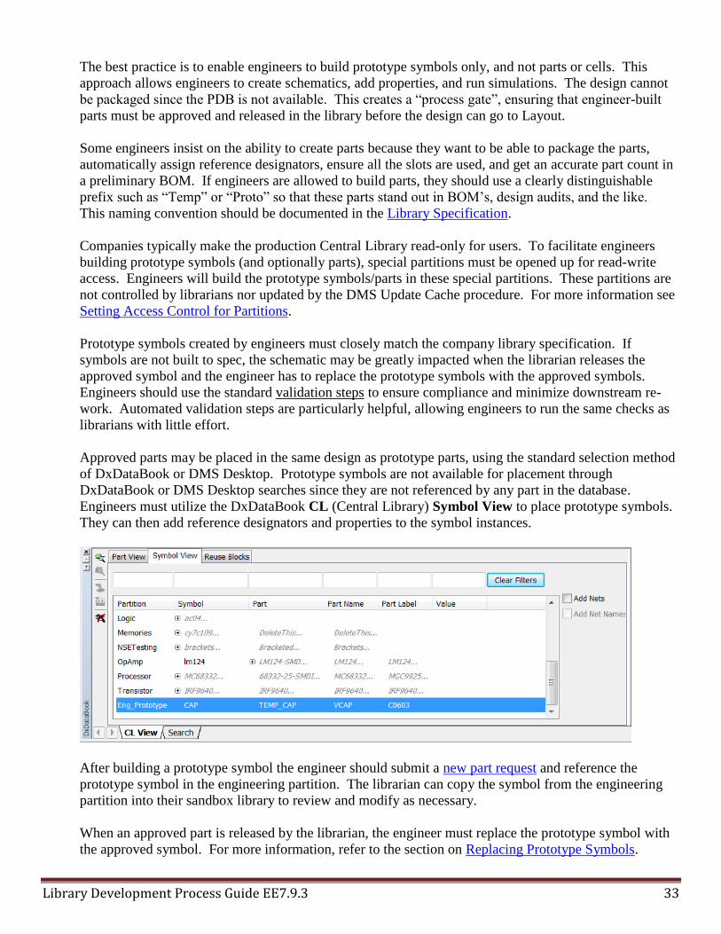
Approved parts may be placed in the same design as prototype parts, using the standard selection method
of DxDataBook or DMS Desktop. Prototype symbols are not available for placement through
DxDataBook or DMS Desktop searches since they are not referenced by any part in the database.
Engineers must utilize the DxDataBook CL (Central Library) Symbol View to place prototype symbols.
They can then add reference designators and properties to the symbol instances.
After building a prototype symbol the engineer should submit a new part request and reference the
prototype symbol in the engineering partition. The librarian can copy the symbol from the engineering
partition into their sandbox library to review and modify as necessary.
When an approved part is released by the librarian, the engineer must replace the prototype symbol with
the approved symbol. For more information, refer to the section on Replacing Prototype Symbols.

Library Development Process Guide EE7.9.3 34
5. Library Development Process Overview
The following “swim lane” diagram shows the key steps in the new part development process. Steps are
executed in chronological order from left to right. The horizontal “lanes” indicate different areas of
responsibility.
For customers who wish to modify this diagram for their own purposes, it is available in PowerPoint
form on the Migration Community at the following link:
http://communities.mentor.com/mgcx/docs/DOC-2932
6. Part Research, Request, and Approval
6.1 Part Research
When identifying parts to use in a design, engineers should always search the DxDesigner/Expedition
library first. It is always best to use an existing library part where possible since every new part has a
cost associated with component engineering, library part creation, purchasing, database entry, and so on.

Library Development Process Guide EE7.9.3 35
Engineers can use DxDatabook to search for parts, filtering on types of parts and desired properties to
find a match.
DMS Desktop provides more robust search capabilities allowing engineers to search on part properties
and also on characteristics of the associated symbols and cells. DMS Desktop offers:
True relational database with Google-like searching
Part comparison
Search presets speed frequently used searches
DMS also offers the web-based Library Researcher tool which allows users to search the library and print
data sheets from a standard web browser.
Another good way to find suitable parts is to review the parts used in existing designs. DMS allows users
to view bills of material (BOMs) and to place parts directly from BOMs.
Some project managers create a shopping list of approved parts for a project and restrict engineers to
placing parts from the list into their schematic.
If an engineer cannot find a component in DMS/DxDataBook to match the design requirements, they
must identify a suitable component and request that it be created and inserted into the corporate library.
Methods of research the engineer may use include:
Search using internal databases
Search using individual vendor web sites
Search through part distributors
6.2 New Part Request
A New Part Request must be initiated when engineers need to introduce a new part into the system. The
ideal part request process has the following characteristics:
Request form is electronic
Request form allows attachment of datasheets, prototype symbols, and models
Request is added to a database for tracking and updating as the work progresses
All downstream activity is automatically spawned from the request
Component engineering approval
DxDesigner/Expedition library part creation
3D Mechanical model creation
Simulation model creation (analog, IBIS, etc.)
Part approval and creation activities are tracked and made visible to the requestor
6.3 Modify Part Request
When an existing library part needs to be modified a Modify Part Request can be used. This is like a
New Part Request but does not require the same level of component engineering and approval since the
part number is already in the system.
Tasks to cover in a Modify Part Request include:
Add existing part to another production library
Modify part view (symbol, cell, padstack)

Library Development Process Guide EE7.9.3 36
Add alternate symbol
Add alternate cell
Add property to component database
6.4 DMS Part Request Management
DMS offers functions for submitting, fulfilling, and tracking part requests. In a non-DMS environment
the Mentor Graphics tools provide no such functions and customers develop their own paper-based or
electronic request forms.
6.4.1 DMS Part Request Manager
The Part Request Manager is a web-based tool that allows engineers to do the following:
Submit New Part Requests - displays a dialog box with text entry and selection fields with which to
enter required information to create a request. The request originator can include informational
attachments (such as specifications and data sheets) with the new part request to assist the librarian.
Change an existing Part Request - allows the engineer to change a part request still in a submitted
state (for example, delete a request that has not been accepted by the librarian, remove or add
attachments to the request, and so forth).
Search for and return a list of Part Requests - Allows the entry of search criteria that then returns a
list of matching requests, along with the status and other information from each request.
See modified Part Requests - Presents a special tab that allows a submitter to see which requests
have not yet been accepted or that were recently modified by a librarian.
Part requests are managed as objects in the DMS database. Librarians accept and fulfill part requests
using Librarian Flow Manager.

Library Development Process Guide EE7.9.3 37
For more information refer to the DMS Librarian User’s Guide.
http://supportnet.mentor.com/docs/201201058/docs/htmldocs/dms_libr_gd/index.htm
6.4.2 DMS Librarian Flow Manager
Librarian Flow Manager allows librarians to track a part request through the part creation process until
the part/component is created and released into the corporate library in DMS. Librarians use the standard
library creation tools to create or modify library data. Librarian Flow Manager adds an additional request
management tab to the DMS Librarian interface as shown below.
For more information refer to the DMS Librarian User’s Guide.
http://supportnet.mentor.com/docs/201201058/docs/htmldocs/dms_libr_gd/index.htm
6.4.3 DMS Process Flow Manager
With the DMS Process Flow Manager, a designated process administrator (usually a librarian) can create
a custom process flow with pre-defined steps to represent a request tracking and approval process that is
more meaningful than the default status-driven process available without the DMS Process Flow
Manager. Steps defined in the custom process flow can occur in sequential or parallel order (or a
combination of both). Each step in a process flow has one or more authorized users that can either
approve the step or reject the step.
When Process Flow Manager is used, additional tabs are added to the Part Request object in DMS.
Process Flow - Lists the active step (that is, where the object is in the process), the user responsible for
approving the step, a button allowing approval or rejection of a step, and a listing of approvals for each
step in the process flow.
Process Tracking - Provides a history of the process flow of the object by listing all step status
changes, who performed the status change, and when the status change occurred.
For more information refer to the DMS Process Flow Manager User Guide.
http://supportnet.mentor.com/docs/201201058/docs/htmldocs/dms_pfm_user/index.htm

Library Development Process Guide EE7.9.3 38
6.5 Part Approval and Part Number Assignment
After a part request is submitted it is usually approved by a component engineer familiar with both
company standards and the requirements of the particular project for which the part was requested.
Company part numbers are typically assigned only after the request is approved.
Depending on how long the component engineering process typically takes, companies differ in whether
they require component engineering approval before allowing librarians to build the CAD library data.
The most popular approaches are summarized below.
Strict requirement for component engineering approval
Component engineer must approve each request before any work is done by librarians.
Component engineer assigns a company part number upon approval of the request.
Benefits
Librarians do not waste time building CAD library data for requests that are rejected.
Unapproved parts do not make it into the library.
Drawbacks
Component engineering effort is a bottleneck slowing librarian response time.
Librarians build temporary part prior to component engineering approval
Librarians are permitted to build parts prior to component engineering approval, using a temporary
part number. Some companies allow the librarian to build the cell, while others permit building only
the symbol and part (PDB) to support schematic capture and simulation.
Component engineer must approve each request before the part is given a valid company part number
and moved to an “approved” state in the CAD library.
Component engineer assigns a company part number upon approval of the request. Librarian updates
the CAD library (PDB and DMS/DxDatabook) accordingly.
Benefits
Librarian response time is improved.
Engineers get symbols and parts quicker in order to begin schematic capture and simulation.
Drawbacks
Librarians may waste time building parts that are rejected by component engineering.
Engineers may waste time designing with parts that are rejected by component engineering.
No requirement for component engineering approval
Companies without a formal component engineering function may have the librarians perform basic
steps such as looking for alternative parts already in the library.
Another factor to consider when implementing part approval and library creation workflows is whether
engineers are allowed to build their own parts. To reduce the effect of the component engineering delay
on the first (strict) approach above, some companies allows engineers to build a prototype part and begin
schematic capture and simulation. If the part request is rejected they must remove the prototype part
from the design and find an alternative. If the part request is approved, they must replace the prototype
part with the approved part once built and released by the librarians.

Library Development Process Guide EE7.9.3 39
7. New Part Creation Process
7.1 Overview
At a minimum, a fully-defined DxDesigner/Expedition library part must have a symbol, a cell, and a part
(PDB) element. Additionally, companies add properties that are used to describe the part and drive
different aspects of the design flow. Simulation models such as IBIS and SPICE may also be required
depending on engineering requirements.
The sequence of tasks for part creation and insertion into the component database is shown below.
The sections below provide additional information about each element type.
7.2 Symbol Creation
This section gives an overview of symbol creation concepts and best practices. For detailed information
on how to build symbols please refer to the following documents.
Library Manager Process Guide
http://supportnet.mentor.com/docs/201111030/docs/htmldocs/lm_proc_gd/index.htm
DxDesigner Symbol Editor
http://supportnet.mentor.com/docs/201111030/docs/htmldocs/dxd_symbol_editor/wwhelp.htm

Library Development Process Guide EE7.9.3 40
7.2.1 Location of Symbols
DxDesigner allows symbols to be created and used from two locations as described below.
Library Type Description
Central Library Library supporting DxDesigner and Expedition in the Integrated flow.
Central Libraries may be managed by DMS.
Local Symbols
Symbols build directly in a DxDesigner schematic database using File ►
New ► Local Symbol. This method should not be used in the
DxDesigner/Expedition integrated flow, except to build design-specific
elements such as hierarchical blocks.
Distributed Library
Symbol-only libraries used in the DxDesigner Netlist flow. This type of
library cannot be used in the DxDesigner/Expedition integrated flow and is
mentioned here only to define the term that may be encountered in other
documents.
7.2.2 Types of Symbols
DxDesigner supports several types of symbols as shown below.
Symbol Type Description
ANNOTATE
Defines additional graphic information to annotate in a design. ANNOTATE
symbols represent graphics only (for example, schematic borders and no-connect
indicators). ANNOTATE symbols do not forward annotate to Expedition PCB.
COMPOSITE Defines a symbol with an underlying schematic (used to represent hierarchy).
MODULE Defines a general purpose symbol to represent PCB components and HDL or
SPICE models.
PIN
Defines a single pin component (typically representing power rails and
hierarchical ports in a symbol). Power rails use the Global Signal Name property
to assign power nets that are global in scope.
In the context of building electronic parts, all discussion of symbols in this document is related to
MODULE symbols.
7.2.3 Using Bus Pins
A bus pin is a single pin on a symbol that represents a range of pins. D[8:1] in the image below
represents a signal bus pin, where one pin represents 8 bits (D8…D1). A user would connect an 8-bit bus
to the symbol pin and all 8 bits are connected. In the case of power/ground bus pins, a single symbol pin
is defined with a range to notate that several pins are connected to the same power/ground net. In the
example below GND[10:1], implies there are 10 ground pins (GND10…GND1).

Library Development Process Guide EE7.9.3 41
Using bus pins in DxDesigner is not recommended due to several reasons:
Bus pins must be connected by a bus rather than by a standard net
Global signal nets attached to bus pins require a special syntax (e.g. {GND}10 as shown above)
Pin numbers displayed as comma-separated lists on bus pins become long
Bus pins do not display correctly in the nets section of Project Navigator
Keyin netlists created from designs with bus pins list net names incorrectly
The recommended approach is to explicitly include all signal pins on the symbols as shown below. For
devices with a high number of power and ground pins, create a separate power/ground symbol.

Library Development Process Guide EE7.9.3 42
7.2.4 Symbol Alternates (different representations of the same logic)
Alternate symbols are different graphical representations of the same logic function, for example a
horizontal and a vertical orientation of a resistor symbol. DxDesigner uses a specific naming convention
where numeric extensions are incremented to indicate alternates (for example, “cap.1, cap.2”). The PDB
entry for a part does not refer to each alternate; rather it refers to the symbol name without the numeric
index (for example “cap”). When the part is instantiated into a schematic, all of the alternates are made
available for placement.
The numeric extension at the end of the symbol is sometimes mistaken for an “edit version”, where
“res.2” would be a newer symbol than “res.1”. This is not the case. The number indicates alternate
views and has nothing to do with when the symbol was built.
The graphics below illustrate how two alternate capacitor symbols are handled in the flow.
Symbol Editor provides tabs to edit each alternate of the symbol “cap”.

Library Development Process Guide EE7.9.3 43
The Library Manager Navigator view shows a single entry called “CAP”. Tabs in the preview window
allow users to view both alternates.
The Part (PDB) Editor lists the symbol as “CAP” with no mention of alternates.

Library Development Process Guide EE7.9.3 44
When placing parts in DxDesigner, users can select which of the alternate symbols to place.
7.2.5 Symbol Fractures (multiple symbols that comprise a single part)
Some parts, especially large parts, require multiple symbols that are combined to comprise the part. This
type of part is sometimes referred to as “heterogeneous” or “non-homogeneous”. The multiple symbols
are sometimes referred to as symbol “fractures”, indicating the part is broken into multiple symbols.
New users sometimes confuse the concepts of alternate symbols and fractured symbols. Alternate
symbols, as described above, are different graphical representations of the same logic function. Fractured
symbols are quite different:
Each symbol must be placed in the schematic in order to fully define and package the part
Each symbol associated with the part is referenced by the PDB entry
The image below shows an IC part fractured into six symbols.

Library Development Process Guide EE7.9.3 45
All fractured symbols are referenced in the part (PDB).
Whenever fractured parts are used in a DxDesigner schematic, it is important that all of the required
symbols are placed. If one or more of the fractured symbols are not placed, Packager will issue the
message below. The UnusedGates.txt file lists the pin numbers associated with the unplaced symbol.
This file should always be checked prior to sending the design to PCB layout since leaving out a symbol
can lead to design failure. Packager finished successfully.
!THE iCDB IS UP-TO-DATE!
An unused pin and gate report has been written to
Integration\UnusedPins.txt
An unused gate report for gates not in schematic has been written to
Integration\UnusedGates.txt
7.2.6 Creating Generic FPGA Symbols with I/O Designer (Schematic Update flow)
I/O Designer provides two usage methods, or “flows”, which differ in how library data is handled.
Schematic Update Flow – uses generic symbols built by librarians and manages design-specific changes
through the assignment of net names and the use of hierarchy.

Library Development Process Guide EE7.9.3 46
Schematic Export Flow – creates instance-specific symbols and parts based on the programming of each
FPGA instance in a design.
A “generic” FPGA symbol set is one built by a librarian to represent an FPGA in a basic fashion without
regard for any particular programming applied to the FPGA in a particular design. I/O Designer
provides a method of creating generic symbols and storing them in the library.
IO/Designer offers a “Librarian Project” mode that provides librarians working with easy access to
commands and windows used to create generic FPGA symbols and include them in a Central Library. In
Librarian Project mode, the regular set of toolbars is replaced with a single command bar, and the menus
and settings are simplified to display only the commands and entry boxes related to symbol creation.
In a DMS environment the symbols and PDB created by I/O Designer should be written to a sandbox
library, from which they can be loaded into DMS.
For more information on building symbols with I/O Designer refer to the following document.
I/O Designer for FPGA User Guide
http://supportnet.mentor.com/docs/201111030/docs/htmldocs/iod_fpga_user/index.htm
7.2.7 Creating Instance-Specific FPGA Symbols with I/O Designer (Schematic Export flow)
When using the I/O Designer Schematic Export flow, engineers create unique symbol fractures based on
the programming of an FPGA. These symbols reflect the specific implementation of an FPGA better
than “generic” symbols created by the librarians. The mapping of symbol pin name to cell pin number is
also customized in this case, requiring a unique PDB entry.
Note: users are not required to create unique symbols and PDBs for FPGA’s. As mentioned above, the
I/O Designer Schematic Update flow allows the use of generic symbols from the corporate library.
After using I/O Designer to create unique PDBs and symbols for each programmed FPGA in a design,
companies have two choices regarding how to manage these library elements:
Option 1: keep unique symbols and PDBs in the design library. This is the simplest approach
Option 2: load unique symbols and PDBs into the corporate library. This supports design reuse by
making all parts available in the library.
The diagram below shows option 2 implemented in a DMS library. Several key features are shown:
A suffix is added to make programmed instance-specific PDB part numbers unique
The suffix making each FPGA instance part number unique is removed from the BOM.
Instance-specific PDBs and symbols are loaded into DMS. Each unique part number creates a unique
component in DMS.
Instance-specific components are related to a “root” component in DMS. The root component
represents a generic description of the FPGA. This allows automatic synchronization of properties
from the root component to the instance-specific components, so that the component definitions are all
the same and only the PDB and symbols differ for each programmed variation of the FPGA.
DMS component properties are automatically updated from a separate corporate database, for example
a PLM system. Only the “root” part numbers are included in the corporate database. The “root”
component properties are updated from the corporate database, and the properties are then propagated
to the related instance-unique components.

Library Development Process Guide EE7.9.3 47
The illustration below shows that the PDB part number for each programmed instance is made unique by
adding a suffix after the pipe (‘|’) character. While other methods can be used, this is the recommended
approach.
Exporting Symbols and Parts to a Central Library
Before exporting, one must set the destination Symbol and Part partitions in the I/O Designer ► Setup
► Settings dialog on the Projects page.

Library Development Process Guide EE7.9.3 48
Note that I/O Designer writes to the Central Library associated with the DxDesigner project. Since the
Central Library is usually write-protected, a particular partition may need to be created with write access
for engineers. This partition would be used by Librarians to copy the design-specific symbols and parts
generated by I/O Designer into a sandbox library for validation, cleanup, and insertion into the corporate
library. This follows the same approach described in the section entitled Enabling Engineers to Build
Prototype Parts. For more information also refer to Setting Access Control for Partitions.
Once the target partition is selected and one or more symbols exist in the project, the symbols and parts
may be exported to the library by invoking I/O Designer ►Export ►Symbols and Part to Central
Library selection, which opens the dialog shown below.
If symbols or parts with the same name as those being exported already exist in the selected Central
Library partition, a warning message appears showing the names of the existing symbols or parts,
requesting confirmation that the user wants to overwrite them.
For more information on building symbols with I/O Designer refer to the following document.
I/O Designer for FPGA User Guide
http://supportnet.mentor.com/docs/201111030/docs/htmldocs/iod_fpga_user/index.htm
Synchronizing Component Properties in DMS
Since all the instance-specific variations of an FPGA are really just changes to the symbol and mapping,
the component-level properties should all be the same. DMS provides the ability to Synchronize
Components, which propagates component properties from the root part to the related instance-specific
parts.
Relationships between root and child components are automatically determined based upon the naming
convention defined in the configuration Toolbox ► Tools ► Component Synchronization. This
makes it easy to add new instance-specific components without having to explicitly link them to the root
for synchronization.
The image below shows the configuration set for the default separator, which is the pipe ‘|’ character.
With this configuration in place, component properties from “ABC” will by synchronized to
“ABC|myproject”. The two components are not otherwise linked in any way.
This dialog also controls which properties (characteristics) are updated by the synchronize function. This
is helpful to avoid overwriting any properties that are specific to the instance-specific components, for
example information related to the programming of the FPGA.

Library Development Process Guide EE7.9.3 49
The user can have the system auto-synchronize the property data whenever a manual edit is done to the
root component properties, or the user can force the system to update all of the components by selecting
Tools ► Plugins ► Synchronize Components.
If a particular component should not be updated from the root component, librarians can set the “synch
exclude” property to “yes”. The default is “no” since users normally want to synchronize any instance-
specific parts they add to the database.

Library Development Process Guide EE7.9.3 50
Component property changes made through the Data Import Wizard or command-line ASCII Loader are
not automatically synchronized. One must run Synchronize Components after any such data loads.
Component property changes made through the IPC scripting interface are automatically synchronized,
just as if the changes were manually made through DMS Desktop.
7.2.8 Accommodating Engineering-built Prototype Symbols
Some companies allow engineers to build prototype symbols to use until librarians build, validate, and
release the requested parts. The recommended process is described in the section entitled Enabling
Engineers to Build Prototype Parts.
Engineers should not create “local” symbols using File ► New ► Local Symbol. The only exception is
that hierarchical blocks are created this way since they are unique to the design.
Symbols built by engineers must match the company specification or else they will have to be rebuilt by
the librarian. Engineers should perform the standard validation steps on the symbols they build in order
to minimize the impact of replacing the prototype symbol with the “official” symbol.
Removing piped suffix from BOMs
Companies typically prefer to remove the piped suffix from part numbers in the Bill of Materials (BOM).
To remove the suffix, add the following lines to the DxDesigner Partlister configuration (*.ipl) file.

Library Development Process Guide EE7.9.3 51
<Preprocessor>
<Rule attribute="Part Number" regexp="(.*)\|(.*)" value="\1" />
</Preprocessor>
7.3 Importing RF Library Symbols
RF design requires a special set of symbols that are synchronized with the RF simulation tool. RF
symbols to use with ADS and AWR are provided as special Central Libraries in the product installation.
The libraries are delivered to %SDD_HOME%\standard\RF. There are two libraries: ShapesLibrary
(ADS) and AWRShapesLibrary (AWR).
RF symbols may be copied into a Central Library using Library Services or by using the
RFSymMergeUtility script. The script is a convenient way to update a Central Library with RF symbols.
To run the RFSymMergeUtility, follow the steps below.
Open a Windows Command Prompt using Windows Start ► type in “cmd” <enter>
cd %SDD_HOME%\common\win32\bin
Enter the command with the desired options as shown below. Optional command line arguments are
shown in [brackets]. Defaults values are shown in bold. If no path is given to the source RF Central
Library, the script automatically uses the delivered ADS or AWR library depending on the option
chosen.
RFSymMergeUtility [-ads | awr] [-rfcl <path to source RF CL>] [-all | (list of partition names) ]
[-update | overwrite] -userCL <path to destination CL>
Running with all defaults imports the ADS library (ShapesLibrary), all partitions, as shown below.

Library Development Process Guide EE7.9.3 52
To import the AWR library (AWRShapesLibrary) use the –awr command line option.
To manage RF symbols in DMS, follow these steps:
Import the RF symbols into a DMS Librarian sandbox
Bulk load the symbols into DMS
Associate the RF-specific partitions to Production Libraries supporting RF designers. Since the RF
symbols are not associated with part numbers, entire RF symbol partitions are associated with
Production Libraries. This is the same method used for other types of “special” symbols such as
documentation and mechanical items.
DMS Update Cache exports the RF symbols to the associated Production Library caches.
RF symbols have no associated part (PDB) or cell in the Central Library. When the RF schematic is
forward annotated to Expedition, a special function creates the RF cell “on the fly” based on parameters
entered on the schematic symbols.
7.4 Importing System Design Symbols
Engineers can use DxSystems Designer to create top-down, integrated, multi-board electro-mechanical
systems. They can work at different levels of detail, from a conceptual flow diagram created by the
system architect, to a wiring diagram that is used by an electrician to build the system. DxSystems
Designer can create systems of any complexity. For example, one can create a simple Multi-board system
consisting of a backplane and daughter boards, a medium complexity system such as a copier machine, or
a highly complex system such as a factory that manufactures semiconductor lithography equipment.
When engineers create a design with DxSystems Designer, they create multiple views of the design.
These views provide differing amounts of design detail.
A Project consists of one or more Architectural Views. An Architectural View is the most abstract
view of the system or a portion of the system.
An Architectural View consists of one or more Functional Views.
A Functional View is a less abstract, more detailed view than an Architectural View.
Each Functional View is associated with one and only one Electrical View

Library Development Process Guide EE7.9.3 53
An Electrical View contains only system content, consisting of connectors, system level blocks, and
the connectivity between them. These objects represent the contents of a PCB board or boards that will
become Expedition Enterprise projects. In addition, an Electrical View can contain electro-mechanical
objects, such as pumps and motors that connect to the board objects.
If DxSystems Designer is being used, library data specific to this tool must be available to engineers.
The DxSystems Designer library can be kept separate of the regular DxDesigner/Expedition library, but it
may be more efficient to combine these libraries. This allows a Systems design to flow down into an
electrical view that utilizes the standard electrical library symbols.
The DxDesigner installation includes a sample DxSystems Designer library at:
$SDD_HOME\standard\examples\SystemDesign\library\SystemDesign.lmc.
These symbols can be imported in to the standard library using Library Manager ► Tools ► Library
Services. In a DMS environment this library can be loaded into DMS and then distributed to the
appropriate Production Library caches.
If DxSystems Designer symbols are imported into an existing library, additional properties must be
defined in Library Manager ►Tools ► Property Definition Editor. The required properties are
described in the documentation and are included in the sample library mentioned above.
For more information refer to the following documents.
DxDesigner User’s Guide for Expedition Flow (“Designing Systems” chapter)
http://supportnet.mentor.com/docs/201111030/docs/htmldocs/dxdesigner_user/index.htm
Library Manager Process Guide (“Managing System Design Symbols” appendix)
http://supportnet.mentor.com/docs/201111030/docs/htmldocs/lm_proc_gd/index.htm
7.5 Importing Analog Simulation Symbols
Mentor provides symbol libraries with the analog simulator products. There are many components that
are used for simulation that would not typically be part of a corporate library. These include symbols for
independent and dependent sources, magnetics, integrators, and similar types of functions used in
modeling. These parts should be imported into the Central Library symbol partitions.
These symbols can be imported in to the standard library using Library Manager ► Tools ► Library
Services. In a DMS environment this library can be loaded into DMS and then distributed to the
appropriate Production Library caches.
The library for HyperLynx Analog is located at:
$SDD_HOME\standard\templates\hyperlynx analog\CentralLibrary\ApSym_CentralLibrary\SymbolLibs
7.6 Padstack Creation
Padstacks are referenced by cells, and thus must be created before cells are created. Padstacks reference
pads and holes, which are also built in the Padstack Editor.
Expedition supports the following types of padstacks. Any padstack type can be included inside of cells,
except for those limited to use in Fablink XE. Expedition differs from some other PCB layout tools

Library Development Process Guide EE7.9.3 54
which require features such as mounting holes and vias to be declared as “pins” when used inside of
footprints.
Symbol Type Description
Pin - SMD
Consists of pads on the external layers. It must have a top and bottom pad
defined. One can optionally define plane clearance and plane thermal pads for
negative plane layers, top and bottom soldermask or top and bottom
solderpaste pads. SMD padstacks cannot have a hole assigned.
Pin - Through
Consists of a plated hole and pads. It must have top, internal and bottom pads
defined. One can optionally define plane clearance and plane thermal pads for
negative plane layers, top and bottom soldermask or top and bottom
solderpaste pads. The center of the hole is the origin of the padstack.
Pin - Die Connection point on top of a silicon substrate, typically the starting point of a
bond wire.
Bondpad Receiving pad for a bond wire, typically the end point of a bond wire.
Fiducial
Consists of a pad on the external layers. It must have both a top and a bottom
pad defined. Fiducials cannot have a hole assigned to them or be associated
with a signal.
Mounting Hole
Consists of a plated or non-plated hole and (optionally) pads. A mounting hole
may have a signal net assigned to it at the time it is added to the Expedition
layout database, without having to include the mounting hole in the schematic.
If users want the mounting hole to have a reference designator and a pin
number (for example, when the mounting hole is a component in the
schematic), then a package cell must be created with a through pin rather than
a mounting hole.
Via
Consists of a plated hole and pads (pads are optional). Signal names can be
assigned when the via is placed in the design, if they are placed in the design
by themselves. Otherwise, net names are determined based on the nets of the
elements to which they are connected.
Shearing Hole
(FabLink XE only)
Used for printed circuit board fabrication, assembly, and testing. Shearing
holes provide a break point when the actual printed circuit board panel is
trimmed (or “sheared”) from the fabrication sheet.
Tooling Hole
(FabLink XE only)
Used for printed circuit board fabrication, assembly, and testing. Tooling holes
hold a printed circuit board panel to a fixture during the manufacturing
process. This fixture is normally trimmed (or “sheared”) from the actual
printed circuit board.
Because proper pad sizing and placement is key to manufacturing success, many companies have strict
guidelines, calculators, and other tools to help determine define padstacks for new part requests. In cases
where manufacturing experts outside the librarian group are involved in padstack definition, the new part
request process should facilitate this interaction.
For more information on padstack creation refer to the following documents.
Library Manager Process Guide
http://supportnet.mentor.com/docs/201111030/docs/htmldocs/lm_proc_gd/index.htm
Expedition PCB User’s Guide
http://supportnet.mentor.com/docs/201111030/docs/htmldocs/exp_gd/wwhelp.htm

Library Development Process Guide EE7.9.3 55
7.7 Cell Creation
Expedition cells represent the physical footprint used in PCB layout. Cells include references to
padstacks as separate elements. Changes to padstacks in the library automatically are reflected in cells
referencing the padstack.
This section provides an overview of cell creation concepts and best practices. For detailed information
on how to build symbols please refer to the following documents,
Library Manager Process Guide
http://supportnet.mentor.com/docs/201111030/docs/htmldocs/lm_proc_gd/index.htm
Cell Editor User’s Guide
http://supportnet.mentor.com/docs/201111030/docs/htmldocs/celleditor_gd/index.htm
7.7.1 Location of Cells
Expedition cells must be located in a Central Library. Each Expedition design also has a local library
containing the parts, cells, and padstacks used in the PCB layout. This library is similar in structure to a
Central Library, except that it has no partitions. The local library is updated with the parts and cells for
the design when Forward Annotation is run. Users may also import additional library items such as vias
and mounting holes through Library Manager ►Library Services. Items in the local library can be
modified using editors invoked from within Expedition.
For more information on the Expedition library structure refer to the section entitled Synchronizing
Expedition Cells with the Central Library
7.7.2 Types of Cells
Cell Type Description
Package
Represent the physical package of an electronic component. Package cells are
associated with parts in the Parts Database (PDB). References to mechanical and
drawing cells may be embedded within package cells, for example to include a
chip carrier in an IC.
Mechanical
Represent objects such as mounting sockets, nuts, bolts, card ejectors, heat sinks,
and washers. Mechanical cells might contain one or more pins (for example, a pin
attached to a heat sink) that appear in layout designs but that have no graphical
representation in the schematic. Mechanical cells can be referenced by package
cells.
Drawing Used for design documentation and composed of drawing objects (sheet borders,
cross sections) and text. Mechanical cells can be referenced by package cells.
Panel Elements that are added to a manufacturing panel to aid in the manufacturing
process.
7.7.3 Embedding Mechanical Cells Inside of Package Cells
Mechanical cells can be referenced, or “nested”, inside of package cells. When this is done, the graphical
items from the mechanical cell appear when viewing the package cell in Cell Editor and in Expedition.

Library Development Process Guide EE7.9.3 56
Nesting mechanical cells rather than building the mechanical items directly into the package cell has
these benefits:
The mechanical item can be built once and reused in many Package Cells.
Librarians can easily provide alternate cells with and without the nested mechanical cell.
The mechanical cell can be assigned a part number in the Cell Editor. This part number will be
included in the Bill of Materials (BOM) generated from Expedition any time a package cell
referencing the mechanical cell is placed in the design.
Drawing cells can be nested inside package cells but they have no part number.

Library Development Process Guide EE7.9.3 57
The Library Manager Navigator view shows the nested mechanical and drawing cells.
7.7.4 Package Group and Clearance Type
The Cell Editor Properties dialog allows entry of properties, placement rules, Package Group, and
Clearance Type.

Library Development Process Guide EE7.9.3 58
Package Group is used to which type of package a cell represents. The Package Group controls certain
behaviors in the Cell Editor and in Expedition. For example, Edge Connector is the only Package Group
that allows surface-mounted pins on both sides of the board.
Package Group can also be used as the basis for creating package type-to-package type checking in CES.
Clearance Type is used to further refine package type-to-package type clearance rules in CES. When
first beginning to use Clearance Types in Cell Editor, none will be available in the pick list, so the name
must be typed in. Once entered, each Clearance Type name is available in the pick list for selection in
any cell.
In CES, Package Groups and Clearance Types both appear as “Pkg Clearance Types” available for
selection when creating clearance rules as shown above.
7.7.5 Cell Properties and Custom Properties
Most properties are recommended to be placed in the DxDatabook/DMS database. Height and
Underside Space differ in that Expedition specifically looks for these properties in the cell and in the
part (PDB). Placing these properties in DxDatabook/DMS and annotating them onto the symbols will
have no effect on Expedition. Height and Underside Space may be entered on the cell, in the Part (PDB),

Library Development Process Guide EE7.9.3 59
or in both places. If defined in both places, the part properties override the cell properties. Height and
Underside Space are used by Expedition’s DRC and mechanical interface (IDF) file export functions.
The cell Height property defines the height from the board to the top of the package. Underside Space
defines the space between the board and the bottom of the package. It is possible to place a cell
underneath another cell if the smaller cell’s height is less than the larger cell’s underside space.
The Custom Properties button brings up a dialog to enter the properties. The custom property names
must be typed in for each cell – there is no pick list.

Library Development Process Guide EE7.9.3 60
7.7.6 Placement Rules
Placement Rules assigned in Cell Editor control which side of the board the part can be placed on and
which rotation angles can be used on each side of the board. The picture below shows a cell restricted to
horizontal orientation on the top side of the board.

Library Development Process Guide EE7.9.3 61
7.8 Part (PDB) Creation
Parts reference symbols and cells, so they are built last when creating new parts.
This section provides an overview of part (PDB) creation concepts and best practices. For detailed
information on how to build parts please refer to the following documents.
Library Manager Process Guide
http://supportnet.mentor.com/docs/201111030/docs/htmldocs/lm_proc_gd/index.htm
7.8.1 Part Numbers and “Mappings”
A given part number can have only a single “mapping” in the Central Library. In this context a mapping
refers to a combination of symbols and cells and the logical-to-physical pin mapping that relates the
symbols to the cells. For example, a part built with implicit power and ground pins has a different
“mapping” than the same part built with explicit power and ground pins included on the symbols.
Since a part number can only have one mapping, some companies create multiple variations of the part
number as separate PDB entries. From the previous example, the PDB entry with implicit power and
ground pins might use the company part number “ABC”, and another PDB entry with part number
“ABC|pg” might be created to provide the mapping with explicit power and ground pins.
There is no particular naming convention required by the tools, but the use of the “pipe” character as
shown in this example is the recommended practice. This technique was popularized by users of the
Design Architect/Board Station flow, and many carried the practice forward as they adopted
DxDesigner/Expedition.

Library Development Process Guide EE7.9.3 62
It is recommended to avoid multiple mappings where possible in order to simplify the library and BOM
creation process. One situation where multiple mappings for the same part may be required is when
users adopt the I/O Designer “Schematic Export” flow.
7.8.2 Handling Design-Specific PDB Entries for Programmable Parts
Unlike other types of parts, programmable parts are often modified at the design level. The I/O Designer
“Schematic Update” flow proves a convenient method of creating unique symbols based on the
programming of an FPGA. These symbols reflect that implementation of the FPGA better than any
“generic” symbols created by the librarians could do. The mapping of symbol pin name to cell pin
number is also customized for these parts, requiring a unique PDB entry.
Options and methods for handling these unique programmed FPGA instances is covered in the section
entitled Handling Design-Specific Symbols for Programmable Parts.
7.9 Component Property Entry
Component properties are vital to the creation of a new part. Some properties directly drive how
DxDesigner and Expedition work together, some enable additional capabilities such as simulation, and
others add company intelligence unused by the CAD tools but important for part selection, reports, and
the like.
This section provides an overview of concepts related to property entry. For more detailed information
on properties needed by particular tools, refer to the following documents.
Library Requirements to Support Analysis in the Expedition Enterprise Flow
http://communities.mentor.com/mgcx/docs/DOC-2939
DxDesigner Properties Glossary
http://supportnet.mentor.com/docs/201111030/docs/htmldocs/attr/wwhelp.htm
7.9.1 Determining Required Properties and Where to Place Them
The first step toward understanding what properties are required in a DxDesigner/Expedition library is to
document what tools are to be enabled in the flow. Given the tool requirements, engineers and librarians
work together to determine the properties that must be included in the library to drive those tools. The
properties required will differ by part type. Lastly, engineers and librarians must decide where the
properties are to be stored from several options – the DxDatabook/DMS component database, the library
part (PDB), the library symbol, or the library cell. All of these decisions should be captured in the
company library specification.
In addition to the properties needed by the design tools, there may be additional properties such as
approval ratings, cost, lead time, reliability ratings, and the like which are desired by engineers for
informational and reporting purposes. An assessment of engineering wants and needs should be
conducted to capture these as the library is being designed. For each property it is important to document
the purpose and who is expected to enter the data.
The following table shows options available for property placement. Product documentation helps
explain the properties needed for each tool. The few examples given are strictly for illustration.

Library Development Process Guide EE7.9.3 63
Property DMS
Comp
Annotate
to
Symbol?
Library
Symbol
Library
Cell
Library Part
(PDB)
Manually Add
to Symbol
Instance
Value
Vendor
Forward to PCB
Height Optional –
overrides cell
Frozen Package
The great majority of properties should be stored in the DxDatabook/DMS database. These properties
drive part selection as described in the section entitled Filtering Part Selection Based Upon Database
Properties. Some properties are used strictly to help guide part selection and are not added to the symbol
(annotated) when parts are placed in a schematic. Other properties are annotated to the symbol to enable
certain tool functionality or to enhance schematic documentation.
When component database properties are annotated to the schematic symbol upon instantiation, the
annotated property may be visible or invisible. If the property is visible, a placeholder property should be
built into the library symbol in order to control the font, orientation, location, and so on. It is not
necessary for all annotated properties to be visible. As an example, a number of invisible properties may
be annotated to the symbol in order to drive a particular simulator. The simulator requires the properties,
but the engineers do not want to see the properties onscreen or on printed schematics.
Height and Underside Space differ from most properties in that Expedition specifically looks for these
properties in the cell and in the part (PDB). Placing these properties in DxDatabook/DMS and annotating
them onto the symbols will have no effect on Expedition. Height and Underside Space may be entered
on the cell, in the part, or in both places. If defined in both places, the part properties override the cell
properties. Height and Underside Space are used by Expedition’s DRC and mechanical interface (IDF)
file export functions.
Depending on the types of properties required, people with different skill sets and responsibilities may be
required to help fully define the part. For example, electrical engineers, component engineers, signal
integrity experts, and purchasing agents may need to contribute to the property set in addition to the CAD
librarians. The following sections describe methods for entering properties using DxDatabook and DMS.
7.9.2 Property Entry – DxDataBook without DMS
When a non-DMS DxDatabook configuration is associated with a Central Library, users can access
parametric data associated with parts in the Central Library using the Edit Parametric Data popup menu
command in the library navigator tree as shown below.

Library Development Process Guide EE7.9.3 64
As mentioned above, it may be necessary for resources other than librarians to contribute to the property
definition. Non-librarians typically do not have access to Library Manager, so they need another method
for entering properties in the database. Some database tools, such as Microsoft Access, provide a user
interface that allows editing. Other databases would require some sort of data entry menu to be
developed.
7.9.3 Property Entry – DMS
DMS Desktop provides a rich user interface for component data entry, searching, and comparison,
accessible through a thin desktop client or web browser. Through the assignment of formalized roles,
users can be granted access to enter certain types of data, for example component properties, without
being able to modify other types of data such as the CAD library elements associated with the
components.
Note: DMS refers to properties as “characteristics”. Every object in the DMS database can have
characteristics, but the properties being discussed here are component characteristics. Think of these as
properties related to the part number.
DMS also provides the ability to load component properties into the database from ASCII files. The
DMS Data Import Wizard provides a step-by-step graphical user interface to import formatted ASCII
files. Optionally, the ASCII Loader can be invoked in a menu-free “batch” command line operation.
Using the ASCII loading method is a good way for people who do not have access rights to add
component data through DMS Desktop to contribute their information. They can give the ASCII file to a
librarian and the librarian can run the ASCII loader. The ASCII loader can also be used to synchronize
DMS component data with another database such as a PLM system. Part numbers and properties can be
exported from the external database, formatted, and loaded into DMS as a batch transaction.

Library Development Process Guide EE7.9.3 65
DMS provides a means of synchronizing component properties from a “root” component to one or more
related components, as described in the section entitled Creating Instance-Specific FPGA Symbols with
I/O Designer. Properties entered through DMS Desktop are automatically synchronized to the related
components, whereas properties updated through the Data Import Wizard are not.
7.10 Simulation Models and Properties
The Expedition Enterprise flow provides comprehensive board design and analysis capability. Each
simulator requires a set of models and symbol properties. The sections below provide an overview and
where to find more information.
7.10.1 Simulation Models Overview
Simulation models are typically built by engineers rather than by librarians. Simulation models can be
stored anywhere on the file system. To coordinate modeling efforts and maximize reuse, many types of
models can be stored within the Central Library structure. Centrally locating models in this manner helps
ensure consistency and decrease redundant work. In order to achieve these benefits, librarians and
administrators must work closely with engineers to ensure that users have the flexibility to create their
own models, modify versions of existing models, submit new models to the library, and so forth.
Engineering departments often believe working with the library team and adhering to security and
process controls typical of corporate libraries is too difficult and choose to manage their own models
separate of the CAD library. With careful planning and sensitivity to the needs of users the correct
balance between flexibility, reuse, and control can be found.
7.10.2 IBIS Models and Signal Integrity Analysis
Signal Integrity (IBIS) models can be stored in the Central Library IBISModels folder for all engineers
to share. The models can be mapped to components using a Qualified Parts List (QPL) file. The QPL
file maps a Part Number to an IBIS model. Each user then points to this file from HyperLynx BoardSim.
Qualified Parts List File (QPL file) format.
IC, CLOCK-701V, "National CGS701V", 701V.IBS, CGS701V
IC, RAM-512, "MemWell SDRAM512", MEMS.EBD, SDRAM512

Library Development Process Guide EE7.9.3 66
If a QPL file is not centrally managed, designers must create a REF file, which maps reference
designators to model names, for each design. HyperLynx supports both methods of model mapping.
The QPL file can be located anywhere, but the recommendation is to include it in the IBISModels folder
under the Central Library. The path to the QPL file is stored in the HyperLynx configuration file bsw.ini
file, which is found in the HyperLynx install area.
7.10.3 Power Integrity Simulation Models
HyperLynx PI is used for power integrity analysis. Only capacitor models are required. Capacitor
models are stored in a special file format and are located in the HyperLynx model search path.
Starting with HyperLynx PI 8.1, the Qualified Parts List (QPL) file may be used to assign models to
capacitors. The model is assigned based on the Part Number property on the component, which maps to
Part Name in the decoupling wizard. This is the same QPL file described above for use with signal
integrity models.
7.10.4 Analog Simulation Models
Analog simulation models can be managed through Library Manager. When a new Central Library is
created, model partitions are automatically added for Spice and Verilog models. Users may then add
additional sub-partitions as shown below. A folder called VHDL is also created, but VHDL models are
not supported at this time.
Library Manager provides functions to import, create, copy, edit, rename, and delete models.
Models may be associated, or “mapped” to parts through Library Manager. The mappings can be viewed
through the Navigator.

Library Development Process Guide EE7.9.3 67
Models are associated to parts through Tools ► Simulation Model Properties. Alternatively, this
dialog box opens with a right-mouse click on either a part or model in the Navigator and selecting Add
Model to Part or Add Part to Model from the popup menu.
The Simulation Model Properties dialog box allows users to associate models with parts in the following
ways:
Assign models to part numbers
Assign symbol pins to model ports
Map symbol properties to model parameters
For more information refer to the Library Manager Process Guide (Appendix L)
http://supportnet.mentor.com/docs/201111030/docs/htmldocs/lm_proc_gd/index.htm
7.10.5 HyperLynx Thermal Simulation Models
Thermal models are typically not included in the Central Library. HyperLynx Thermal uses a working
library created in each design. Symbols can be created in the design-specific working library in the
following ways:
Models may be copied from HyperLynx Thermal standard master library (betasoft.mlb) installed with
the product.
A direct export is available from Expedition PCB (Analysis ►Export to HyperLynx Thermal),
which creates the models needed for the design. These models are named the same as Part Numbers,
and include properties read from the design and the CES rules. After being created, the models can be
edited using Edit Part as shown below.
Properties that can be read from CES include the following:
Power Dissipation
Junction to case thermal resistance (theta-jc)
Casing temperature limit
Junction temperature limit
The image below shows the interface used to manage the HyperLynx Thermal working library. The
working library is found in the design project structure as an .hlt file.

Library Development Process Guide EE7.9.3 68
Edit Part brings up a menu to review and modify models.
HyperLynx Thermal reads board and component information from mechanical interface (IDF) files
generated from Expedition. This file can include height values read from the library PDB or cell.
Data exported from Expedition/IDF file is combined with thermal-specific properties to create a fully
defined thermal model. This data is saved in the working library, which appears in the project as an .hlt
file.

Library Development Process Guide EE7.9.3 69
A new capability introduced with HyperLynx 8.2 allows saving thermal characteristics to an IBIS model.
The IBIS model contains thermal-specific properties as comments. Other physical properties shown in
the Edit Parts dialog continue to be read from IDF and stored in the working library (.hlt file).
7.10.6 Simulation Model Properties
The same library that is used for design capture and layout can be enhanced to support simulation.
Mentor-delivered library parts for RF, system, and analog design can be read into the corporate library.
Regular components used in PCB layout are enhanced by adding specific properties to drive each type of
simulation.
Simulators require a number of properties to be assigned to schematic symbols to specify model names,
electrical values, and other parameters used in simulation. While it is possible for engineers to add
properties to each symbol instance in a schematic, it is much more efficient to assign the properties in the
corporate library.
If a symbol is unique to a specific part, then the all the properties can be placed on the symbol in the
library. If the symbol is generic (such as a 5-pin opamp or a resistor), then the properties should be
included in the DxDatabook/DMS database and annotated to the symbol upon instantiation.
When adding properties to an existing library, the new properties must be defined in Library Manager
►Tools ► Property Definition Editor. In this menu new properties can be defined from scratch or can

Library Development Process Guide EE7.9.3 70
be imported from other libraries using the Advanced ►Import capability. For example, properties
defined in the sample libraries delivered for HyperLynx Analog or DxSystems Designer can be imported.
For detailed information on properties required for each type of simulation, refer to the following
documents.
Library Requirements to Support Analysis in the Expedition Enterprise Flow
http://communities.mentor.com/mgcx/docs/DOC-2939
DxDesigner Properties Glossary
http://supportnet.mentor.com/docs/201111030/docs/htmldocs/attr/wwhelp.htm
7.11 Mechanical Model Creation and Assignment
3D mechanical models are typically created by the mechanical engineering department only for certain
components such as connectors. For parts having no corresponding mechanical model, the mechanical
interface (IDF) file includes a shape created by applying the Height property to the placement outline(s)
built into the cell. Multiple placement outlines can be placed in a cell, each with their own height. It is
also possible to build the Height property into the part (PDB), in which case the PDB property overrides
the values entered in the cell.
Where 3D mechanical models are created, the ECAD librarian should work with the MCAD engineer to
ensure that the Expedition cell and 3D model match in key ways:
The Height property entered in the cell (or PDB) matches the height used in the mechanical model
The origins of the Expedition cell and 3D model are at the same location (e.g. pin 1).
The Expedition cell and 3D model are oriented the same around the origin (horizontal or vertical)
The association of Expedition cell to 3D mechanical model names is typically achieved by naming the
two files the same. PTC Pro/Engineer supports a file called ecad_hint.map which stores the cell name to
3D model name mapping. This links cell names to 3D Pro/Engineer .prt and .asm files.
The Expedition mechanical interface (File ► Export ► IDF) creates two files.
EMN file contains board data:
PCB Outline
Component Location
Component Orientation
Hole Information
Keep In and Keep Out Regions
EMP file contains component library data:
ECAD outlines for every component
ECAD component height information
7.12 Reusable Block Creation
The concept of design reuse is to create circuit blocks representing either logical-only or logical-physical
designs for use in multiple host designs. Design reuse can save valuable time by avoiding redesign of
identical circuitry. These circuit blocks, called reusable blocks, allows the use of verified circuitry with

Library Development Process Guide EE7.9.3 71
the ease of placing a single block in a design. A reusable block and all its associated design data are
stored in a Central Library so it can be placed in host designs that reference the same Central Library.
There are two types of reusable blocks:
Logical-Only - a reusable block that contains front-end (schematic) design data only and an associated
reusable block composite symbol.
Logical-Physical - a reusable block that contains front-end and back-end data including the schematic,
PCB layout, and reusable block symbol and cell.
The source design for reusable blocks can be a flat schematic or hierarchical schematic. However, when
users place a reusable block in a host design, it is instantiated as a hierarchical block. All library
elements (parts, symbols, cells, and padstacks) used in a reusable block must be located in the same
library into which the reusable block is inserted for use in schematic/layout projects.
Engineers and PCB designers create the reusable block circuit as they would any design using
DxDesigner, Constraint Editor (CES), and Expedition PCB. Designers use one of the following
strategies to create reusable blocks:
Create a new design to be used as a reusable block.
Adapt a portion of an existing design to be a reusable block.
Typically designers submit the reusable block design to a librarian to have it added to the Central
Library. It is possible to grant designers the access rights to add their own blocks to the library, but more
often this task is entrusted to the librarians. Librarians use Library Manager ►Tools ► Reusable
Blocks Editor to create and verify reusable blocks. The creation and verification process creates the
composite (block) symbol that represents the circuit in a schematic and creates a reusable block cell to
represent the circuit in layout. For logical-physical blocks, the creation process also creates a Rule Area
from the board outline shape found in the design. This allows the CES rules associated with the reusable
block to be assigned to the Rule Area when placed in a host design.
Reusable blocks appear in the Library Navigator Tree under the Reusable Blocks node. Reusable blocks
with a red icon indicate an unverified reusable block. Reusable blocks with a green icon indicate a
verified reusable block. Reusable blocks must be verified before they can be used in a host design.
Reusable blocks can be edited directly from Library Manager. Reusable blocks cannot be modified once
they are verified, as the data is in a read-only state. To make changes, the librarian must first “unverify”
the block, after which the editors can be invoked to make schematic and/or layout changes. After the
changes are made the reusable block must again be verified. After incorporating changes, the timestamp
on the reusable block is updated. Designs that use this reusable block are automatically updated the next
time users run Forward Annotate with one of the options to extract newer central library data.
Verified reusable blocks are placed in DxDesigner and Expedition like a component. Reusable blocks
appear on a special tab of the DxDatabook placement dialog. Options are provided to control reference
designator assignment within the block. When placing a logical-physical reusable block in a host design,
the software performs AutoMerge to synchronize layer stackups, global nets (signals), buses between the

Library Development Process Guide EE7.9.3 72
reusable block and the host design. If AutoMerge cannot resolve these problems, the software generates
messages that describe the problem. Use the Merge Layers, Merge Globals, and Merge Buses commands
(from the Reuse Block tab in DxDesigner) to invoke dialog boxes to manually resolve these problems.
When placed in a host design, reusable blocks are treated as “locked” elements. The contents inside the
block cannot be modified since that would deviate from the definition of the certified library circuit.
If users must modify the contents of the reusable block, reusable blocks can be turned into normal design
elements with no link back to the reusable block in the library. In DxDesigner, use Edit ► Dissolve RB
(Reusable Block) Link to convert an existing logical-physical reusable block in a host design to a
normal hierarchical block. If there are multiple instances of the reusable block in the schematic, all
instances will be dissolved. This may defeat the purpose of using a certified reusable block in the first
place, so using this option should be carefully considered.
If layout designers need to edit the physical objects within a logical-physical reusable block placed in an
Expedition design they can select the reusable block and select Edit ► Modify ► Flatten Reuse Block
to ungroup the reusable block elements and allow manipulation with any elements (for example, parts
and traces) in the design. The physical objects and components associated with the design will initially be
locked and cannot be edited. To edit the reuse block contents after flattening, click Edit ► Unlock.
Librarians, engineering management, and administrators should carefully consider and plan the ECO
strategy for reusable block versioning, maintenance, and archival before beginning to use them.
Remember that once a reusable block is verified and used in host designs, any subsequent changes to the
reusable block could significantly impact existing designs that use that reusable block. Therefore, it is
extremely important that companies consider the ramifications of modifying, renaming, deleting, or
replacing a reusable block before implementing an ECO on a reusable block.
The illustrations below depict the workflows for creating, verifying, and placing reusable blocks.
For more information refer to the Reusable Blocks Process Guide.
http://supportnet.mentor.com/docs/201111030/docs/htmldocs/dx_exp_reuse/index.htm

Library Development Process Guide EE7.9.3 73
7.12.1 Logical-Only Reusable Block Creation and Usage Workflow

Library Development Process Guide EE7.9.3 74
7.12.2 Logical-Physical Reusable Block Creation and Usage Workflow

Library Development Process Guide EE7.9.3 75
7.13 Creating Library Documentation
7.13.1 DMS XML Print Capability
When a user prints any element in DMS the tool provides a default XML output of the meta-data and
graphical representation of the library part. Companies have the opportunity to transform the XML into
their own style using XSLT style sheets, which reformat XML input.
Any referenced style sheet must use the extensible stylesheet language (XSL). DMS does not require a
style sheet when printing. However, if a style sheet is desired, administrators can copy the style sheet
located at $DBEDIR/examples/dfxml2fo.param.xsl, make custom modifications, and then specify the
location to the modified style sheet in the Edit ► Preferences dialog box.
For more information about the extensible stylesheet language, refer to the World Wide Web consortium
web page at http://www.w3.org/Style/XSL.

Library Development Process Guide EE7.9.3 76
7.13.2 Library Manager PDF Documenter
The Library PDF Documenter (File ► Output PDF) generates a report of Central Library contents (part,
symbol, cell, padstack, pad, and hole objects) in PDF format. The report covers the entire library, and
includes textual and graphical information for each element in the library.
PDF files generated by the Library PDF Documenter utility include:
Appendix.pdf - Summary of cell, symbol, padstack, pad, and hole objects in a central library (including
functional relationship between objects).
Cell.pdf - Listing of central library cell partitions and cell objects within those partitions.
Padstack.pdf - Listing of central library padstack partitions and padstack, pad, and hole objects.
Part.pdf - Listing of central library part partitions and part objects within those partitions.
Symbol.pdf - Listing of central library symbol partitions and symbol objects within those partitions.
<pdf_file_name>.pdf - Summary report of all central library partitions and data objects including
common properties (defined in the Property Definition Editor), layout templates, and reusable blocks.
8. Library Part Validation
To ensure that parts are built correctly and in full compliance with the library specification it is important
to have formal validation methods. Whether a part is built by an engineer or by a librarian it should be
subjected to the same validation. Validation tools and techniques are described in the sections below.
8.1 Validating Individual Parts
Each library part should be validated as it is built and prior to being released to the production library.
8.1.1 Checklist Comparison
Perhaps the most common method of validation is for the person who builds each library element to
compare it to checklists describing the company standards.
8.1.2 Peer Review
Many companies require that a second person review each library element before it is released. The
second reviewer may be a peer, a lead librarian, or a designated quality-control person. The workflow
diagrams above show a lead librarian doing the validation and release but the same flow can be
implemented with a peer doing it.
8.1.3 Packaging Parts in DxDesigner
Library Manager provides a “correct-by-construction” paradigm where most simple errors such as
symbol to cell pin number mismatches are avoided during part creation. Despite these checks it is
possible to create parts that do not package correctly. Each new part should be placed in a test schematic
and packaged to ensure it works in the flow.
8.1.4 Library Consistency Utility
The Library Consistency Utility is a scripting solution that checks symbols, cells, and parts against
customer-defined rules. Libraries may share rule sets or individual libraries may have their own unique
rule sets. Since there may be several libraries in the environment, such as librarian sandboxes and quality
control libraries, it is best for each of these to reference the same rule set to ensure consistency. If there

Library Development Process Guide EE7.9.3 77
are multiple library specifications in use then unique rule sets for each specification would be
appropriate.
The Library Consistency Utility will be expanded over time but currently offers the following rule
checking.
Symbols
Checks for the presence of required properties
Checks for valid values for each property (where values are built into the library symbol)
Checks for correct characteristics for each property – font, text size, color, visibility, orientation
Parts
Automatically places the selected part in DxDesigner, packages it, and looks for errors in the Packager
log file
The script is available on the Migration Community at:
http://communities.mentor.com/mgcx/docs/DOC-2903
8.2 Validating Entire Libraries
On occasion it may be necessary to validate an entire library. This need arises when the library
specification is changed or when a new library is introduced from a company merger or translation from
another system. When working with large numbers of parts it is crucial to have some validation steps
automated. Automation available today is described below.
8.2.1 DMS: Library Integrity Checker
Inconsistencies (or mismatches) in case usage of symbol object names and part (PDB) definition of
symbol names in a DMS Librarian sandbox can lead to problems when propagating symbols and PDBs to
the DMS database (which respects case-sensitivity in object names). This can cause broken references
between objects in DMS due case-sensitivity issues. For example, the symbol name in the symbol file,
the part (PDB) definition, and library index file can be of mixed case (because DMS Librarian objects are
case-insensitive). However, mixed case object names can cause problems when loading sandbox objects
to DMS (because DMS enforces case sensitivity).
To ensure consistent case usage between symbol object names and PDB definition of symbol names, use
the Library Integrity Checker in DMS Librarian to scan objects in an existing library for case
inconsistencies between the symbol name, PDB definition of the symbol name, and library index. This
check should be run and inconsistencies resolved before loading data from a sandbox library into DMS.
When scanning the library, the Library Integrity Checker checks for differences between:
Symbol file name and the symbol name given inside the symbol file.
Symbol file name and part (PDB) definition of a symbol name in the part (PDB) definition.
Part (PDB) definition of a symbol name in the part file and symbol name in the library index (.lmc)
file.
The software:
Fixes symbol object inconsistencies in the library based on Repair option settings in the Options dialog
box (or the repair option selected for individual objects in the Take value from column).
Saves all changes to objects in the library and re-indexes the library file.

Library Development Process Guide EE7.9.3 78
Generates the LibraryIntegrityChecker.log file in the LogFiles directory of the sandbox library.
For more information refer to the DMS Librarian User’s Guide.
http://supportnet.mentor.com/docs/201201058/docs/htmldocs/dms_libr_gd/index.htm
8.2.2 Advanced Library Editor (ALE) Integrity Check
The Advanced Library Editor (ALE) is suite of automation scripts that allow bulk checking and
modification of libraries. It is available on the Migration Community.
http://communities.mentor.com/mgcx/docs/DOC-2383
ALE provides a Check Library Integrity function that reports parts (PDBs) missing cells and/or symbols,
symbols with no PDB references, cells with no PDB references, padstacks with no cell references. It
allows automatic deletion of unused library elements.
For more information on ALE refer to the section on Bulk Library Modification.
8.2.3 Verify Parts Script
In order to validate the logical to physical pin mapping configuration in the Central Library parts
database, librarians typically create a test schematic, place the part to be tested, and run the Packager to
ensure that the logic gates can be packaged into the physical package. The Verify Parts script, which is
run from Library Manager, automates this Package test for an entire library or for selected PDB
partitions.
The script is available on the Migration Community at:
http://communities.mentor.com/mgcx/docs/DOC-1762
The script does the following:
Creates a DxDesigner project, called "VerifyParts", that references the Central Library file
currently open in Library Manager
Creates a schematic block for each selected PDB partition.
Instantiates one of each symbol referenced (only the .1 version) for each part number in the
selected partitions. Skip parts that are flagged as "Incomplete" in Library Manager

Library Development Process Guide EE7.9.3 79
Generates a top level schematic instantiates a block symbol to reference the underlying schematic
Runs package.exe in the background, and display the Packager output.
To run the script:
Invoke Library Manager and open a Central Library
Click the File -> Open Script Form menu and browse to the VerifyParts.efm file.
Then select the PDB partition, or All Partitions, and click Go.
When DxDesigner goes away, review the packager log file in the script form.
8.2.4 Library Consistency Utility
The Library Consistency Utility, described above, can be run on an entire library or on selected
partitions.
9. Part Selection Control
Librarians and administrator must provide efficient methods for users to select the correct parts to place
into their designs. The criteria for part selection usually include a combination of the following:
Parts for specific groups of users, for example Texas parts and California parts
Parts previously selected for a particular project
Parts of a certain lifecycle status (approved, not obsolete)
Parts of a certain certification status, such as ROHS compliant
Parts with certain properties such as value, tolerance, rating, reliability, cost, and so on
DxDataBook provides basic capabilities while DMS provides robust capabilities for part selection. The
sections below explain the tools and methods available.
9.1 Creating Central Libraries for Different Groups
A common requirement is to provide different libraries for different groups of users, where the “group”
may be a site, a department, or a project. This section describes how to target unique Central Libraries to
each group.
9.1.1 Non-DMS: Managing Central Libraries for Groups
Without DMS, managing separate Central Libraries is not very efficient. The crudest approach is to
maintain separate Central Libraries with no sharing between them. Many companies operate this way,
with each group being responsible for their own library. Each site follows a simple workgroup
workflow. This results in duplication of effort as the same parts are built multiple times in different
libraries. Worse, the duplicate parts are often built to different specifications, making it difficult to
combine the libraries later when the company begins trying to create a common library.
A more efficient approach is to maintain separate libraries but allow librarians to search each library and
choose parts, symbols, or cells that would be useful to copy into their group library. This approach can
be facilitated by copying all of the libraries to a known location accessible by all librarians. This
improves part creation efficiency but still results in duplication of library elements across multiple
libraries.
The most efficient non-DMS management scheme is to maintain a common library and put every part
built by every group into this library. The common library can then be copied to each group as shown in

Library Development Process Guide EE7.9.3 80
the non-DMS common library workflow. An option within this scheme is to use Library Services to
release specific parts from the Quality Control library to each group-specific production library rather
than copying the entire library to each group.
In a non-DMS environment where a common Central Library is used, each group may have its own
unique DxDataBook database or there may be a database shared by all group. If each group maintains
their own DxDataBook database, then they enter into the database only those parts they want their group
to use. While there may be other parts in the common Central Library, users would not be able to place
them since they are not in DxDatabook.
If there is a common library and a common DxDataBook database, a database field can designate which
groups can use each part. This field can be used a filter when selecting parts from DxDataBook so that
users see only the appropriate parts for their group. In the example below, a user in Indiana (IN) is
searching for parts approved for use by their site.
None of these methods is optimal. DMS makes it much easier to manage a common library and
distribute libraries targeted to certain groups.
9.1.2 DMS: Creating Production Libraries
DMS makes it easy to assign certain parts to certain users through the construct of Production Libraries.
All parts are stored in the DMS database, but only selected parts are associated with a particular
Production Library. In DMS a Production Library is simply a list of part numbers selected by librarians
for a particular purpose. One may create a Production Library for a site, a group, a project, or any other
purpose. Librarians assign part numbers to Production Libraries, and a single part number can be
associated with multiple Production Libraries.
DMS automatically creates a “cache” of library elements for each Production Library through a process
called Update Cache. A Production Library cache is simply a Central Library containing all the parts
associated with the Production Library. The cache is updated with new and/or modified library elements
automatically so librarians do not have to spend time releasing parts to different libraries for different
users. A cache is an output of the DMS library, and is not the master data; thus a cache can be deleted
and re-generated from DMS at any time.
A new capability added in DMS version 7.9.3 allows the creation of “dynamic” Production Libraries.
Librarians can define “search presets” queries that return certain types of parts from the DMS database,
and then associate the search presets with dynamic Production Libraries. All parts meeting the search
criteria are automatically added to the Production Library, and all library elements associated with the
selected parts are automatically written to the Production Library cache. Administrators have options for
controlling when the query is run and the Production Library is updated:
Automatically update on a regular schedule

Library Development Process Guide EE7.9.3 81
Automatically update whenever Update Cache is run
Update on demand.
The example below shows a dynamic Production Library created to support a commercial project in
Texas. The search presets combine to return a set of parts which are commercially available, are ROHS
compliant, are not obsolete, and have a property indicating they are available for use in Texas.
DMS Production Libraries control the delivery of library elements to specific Central Library caches,
resulting in smaller libraries to be distributed to each group of users. This can be very helpful when
libraries must be distributed to users at remote sites across the network. Rather than send all the library
parts to all users, administrators can send just the needed parts to each user group.
Certain types of symbols and cells are not associated with part numbers. Examples are power/ground
symbols, formats, RF symbols, mechanical cells, drawing cells, and so on. Librarians can associated
individual symbols and cells, or entire symbol or cell partitions, to a Production Library in order to
distribute them to the cache.
Production Libraries are also used to limit part selection in DxDesigner. The two part selection tools,
DxDataBook and DMS Desktop, both reference the component information in DMS. Since all of the
company components are in DMS, users could potentially see all part numbers. Since this is not usually
desired, Production Libraries are used to narrow down the users’ options to a pre-determined set of parts.
The basic mechanics of using Production Libraries for part selection are described in the next two
sections.
9.1.3 Using DxDataBook with DMS Production Libraries
DxDataBook is a basic part selection tool that works well for users who normally use the same
Production Library all the time. DxDataBook connects to the DMS database using a “DMS Connector”
which utilizes internet protocols. The connector is set up by the DMS Administrators using the
DxDataBook Connector Wizard as shown below.

Library Development Process Guide EE7.9.3 82
The DxDataBook connection above references the Production Library named “Texas”. Only parts
associated with this Production Library will be available for selection through this DxDataBook
connection. There can be unlimited numbers of DxDataBook connections. Each pre-defined connection
has a URL (hyperlink) associated with it as shown below. When configuring DxDataBook one simply
chooses the correct URL for the desired connection.

Library Development Process Guide EE7.9.3 83
9.1.4 Using DMS Desktop with Production Libraries
DMS Desktop is the DMS tool engineers and designers use for part selection. It can be used instead of,
or in combination with, DxDataBook. DMS Desktop interacts with the DMS database directly and does
not require a “Connection” as is used with DxDataBook. DMS Desktop allows users to select which
Production Library they wish to search. Users also have the option to search the entire DMS library
without considering Production Library limitations. This can be helpful when users are doing part
research. If a user doesn’t find a part meeting their requirements in their normal Production Library they
can expand their search to look across the whole DMS database. If they find a match, they can request
that the desired part be added to their Production Library. This standard approach allows librarians to
build up Production Libraries on an as-needed basis, initially assigning new parts to the Production
Library associated with the parts request and then adding it to additional Production Libraries upon
request.
DMS Administrators have the option to assign a default Production Library to each user and to limit the
Production Libraries that users are allowed to access. This can be helpful to reduce user errors, but care
should be taken to avoid overly limiting the users.
9.2 Filtering Part Selection Based on Database Properties
After the part selection has been narrowed down to the set of parts available in a Central Library or
Production Library cache, the next level of search refinement is to choose parts based on certain
properties. When designing a library, librarians and administrators must work closely with the user base
to understand what properties are important for part selection. Librarians must be familiar with how part
selection works from an engineer’s perspective using DxDataBook and/or DMS Desktop. The basics of
part selection are described in the following sections.
9.2.1 Using DxDataBook for Part Selection
DxDataBook appears the same to DxDesigner users whether the component data is in DMS or in some
other database. The menu allows the user to select a “library” and then to reduce the parts list by entering

Library Development Process Guide EE7.9.3 84
property values to be used as a filter. Here the term “library” does not mean a separate library but really
refers to a database table. For more information on how DxDataBook “library” names relate to the
Central Library partitions and DMS catalog groups, see the section on Library Partitions
The example below shows a selection of resistors with Value (resistance) greater than or equal to 100K.
When configuring DxDataBook it is important to consider the space available on the user interface. If
many properties are available as filters they will not fit onscreen at once and the user will have to scroll
left and right to see all the available fields. Administrators should be prudent in selecting how many
properties to include, and should order the properties with the most important on the left and the least
important on the right in order to minimize scrolling.
9.2.2 Using DMS Desktop for Part Selection
DMS Desktop provides far more extensive capabilities for selecting parts than does DxDesigner. The
sophisticated user interface can be considered more complicated and difficult by some users, so
companies may elect to use a combination of DxDataBook and DMS Desktop. A common approach is to
use DxDataBook to find quick matches in the selected production library, and if nothing is found go to
DMS Desktop for more involved searches across the entire DMS database.
DMS Desktop has the following menu elements for part selection:
Object Classification Pane –allows users to traverse the full hierarchy of component catalog groups
and sub-groups. Parts from the selected catalog group are returned when searches are performed.
Search Criteria Pane – allows users to enter values to be used as search criteria for any properties in
the DMS database for the selected catalog group
Search Results Pane – shows parts matching the search criteria and allows users to initiate actions on
the parts such as place in schematic, show more information, compare with other parts, and so on.
Floating Object Information Pane – shows more information for a selected part
The following picture shows these panes.

Library Development Process Guide EE7.9.3 85

Library Development Process Guide EE7.9.3 86
Users can define and utilize “search presets” to repeat common searches.
Users instantiate symbols into a schematic by selecting the command from the context menu on a
selected part, as shown below.
When instantiating the user is able to choose alternate symbols and cells, choose slots, and pass the cell
name to the schematic.

Library Development Process Guide EE7.9.3 87
9.3 DMS: Creating Project-Specific “Shopping Lists”
In DMS, shopping lists can be built to ease part selection for engineers and to enforce usage of project-
approved parts. A lead designer or project manager builds a shopping list using DMS Desktop. The
shopping list can include regular parts and also reusable blocks from the Production Library. Shopping
lists can be accessed through DxDataBook or DMS Desktop.
9.3.1 Using DxDataBook with a DMS Shopping list
In DxDataBook, the user sees all the parts in the Production Library (through DMS Connector).
DxDataBook can be configured to display the shopping list field as a filter like any other component
property. Users can then set a filter to choose only parts assigned to the appropriate shopping list.
One downside of this approach should be noted: when a part is included in multiple shopping lists users
see multiple lines for the same part number in the DxDataBook results window. So if the shopping list
field is included in DxDataBook configuration then users must filter on it to avoid to seeing multiple
lines for the same part number.
9.3.2 Using DMS Desktop with a DMS Shopping List or BOM
DMS Desktop allows users to define shopping lists and to instantiate parts directly from the shopping list
as shown below. If bills of materials (BOMs) are loaded into DMS then users can choose parts directly
from a BOM to instantiate into a schematic. This is a good way to build up a project from parts used in a
previous project.

Library Development Process Guide EE7.9.3 88
9.4 DMS: Comparing Part Selection Options – DxDataBook and DMS Desktop
Below is a summary of DxDataBook and DMS Desktop capabilities. If is fairly common for companies
to provide both options to users in a DMS environment.
DxDataBook
Works with any database including DMS
Is built into DxDesigner
Provides one level of component partitioning through the “library” selection
Can work with DMS Production Libraries through DMS Connector
Allows use of DMS shopping lists as selection criteria
DMS Desktop
Separate window from DxDesigner; communicates and cross-probes with DxDesigner
Allows choosing different production libraries or searching the entire DMS database
Shows the full multi-tier catalog group hierarchy
Allows searching on any DMS properties without pre-defining which can be used for searching
Allows usage of search presets to repeat common searches
Provides comparison of selecting parts
Allows instantiation from shopping list or BOM

Library Development Process Guide EE7.9.3 89
10. Design and Library Synchronization
An important aspect of the overall library solution is providing the means to synchronize designs with the
corporate library. Both libraries and designs change over time, so users must understand how to perform
typical operations such as:
Remove locally-built and prototype symbols from schematics and replace with approved symbols
Select appropriate part numbers to assign to generic symbols used in early design phases
Verify that properties on schematic symbols match the component database definition
Update properties on schematic symbols when component database properties are changed
Update symbols and cells in designs when the library elements are modified
These operations are usually performed by schematic engineers and layout designers, but it is important
for librarians to understand how they work. The following sections provide an overview of the tools and
methods available for design/library synchronization.
10.1 Replacing Locally-built or Prototype Symbols in Schematics
A recommended design practice is to require engineers to replace all locally-built and prototype symbols
from schematics prior to releasing the design for PCB Layout. Here “locally-built” refers to symbols
built directly in the schematic and “prototype” refers to symbols built by engineers in a library. Both
types of symbols should be replaced with validated parts from the corporate library before PCB layout
begins.
10.1.1 Replacing Locally-Built Symbols
Building symbols local to the design is not recommended. If engineers must build prototype symbols the
recommended practice is to provide access for engineers to add symbols to certain partitions in the
production library. Refer to the section on engineering-built symbols for more information.
There are two common exceptions to the above-stated rule about local symbols:
Design-specific FPGA symbols created by I/O Designer may be retained in the design if this is the
company practice. See the section on design-specific symbols for more information.
Hierarchical block symbols are typically created at the design level and not added to a library
Local symbols may be present in a schematic that was translated from another design tool or from the
DxDesigner netlist flow to the DxDesigner-Expedition integrated flow.
To identify locally-built symbols in DxDesigner, invoke Tools ► List Local Symbols. This will present
a list of any locally-built symbols in the design. To replace the local symbol with a Central Library
symbol of the same name, do the following:
Open DxDatabook by selecting View ► DxDatabook.
In the Symbol View tab, select the local symbol(s) you want to replace.
Right-click ► Substitute Symbol(s).
DxDesigner does the following:
Searches the Central Library for symbols with the same names as the local symbols.
Adds an alias to the symbol name. This alias specifies the Central Library partition which contains
the equivalent symbol.

Library Development Process Guide EE7.9.3 90
Replaces all instances of selected local symbols in the design with their equivalent Central Library
symbol.
If there is no equivalent symbol in the Central Library, DxDesigner produces the following error:
Symbol Definition Substitution Failed
Matching symbol file not found.
In this situation choose from the following options:
If the local symbol has not been added to the Central Library, add it.
If the local symbol has an equivalent symbol in the Central Library but the symbol name is
different, rename the Central Library symbol to match the local symbol.
If the local symbol has an equivalent symbol in the Central Library but the symbol name is
different, replace the local symbol using Edit ►Replace Symbol.
If a local symbol must be added to the Central Library, follow these steps to export it from the design.
In DxDesigner, Open DxDatabook/Symbol View and expand the local symbols structure.
Select all of the symbols available in the local symbols area.
Right button click the selected symbols and choose Export symbol(s). Browse for the target
folder where the exported symbols should be stored. It is recommended to save the symbols
outside of the project structure.
Send the exported symbols to a librarian to have them added to the Central Library. This will
likely require a New Part Request for each symbol, to which the symbol can be attached.
10.1.2 Replacing Prototype Symbols
Prototype symbols are built by engineers and used in schematics before being validated and added to the
standard Central Library partitions by a librarian. As described in the section on engineering-built
symbols, the prototype symbols should be given temporary part numbers. This makes it easier to locate
and replace the prototype parts with approved parts. One may use DxDataBook Live Verification or
DMS Part Replacement to locate and replace the prototype parts.

Library Development Process Guide EE7.9.3 91
Updating with DxDatabook Live Verification
DxDataBook Live Verification allows users to verify that parts in the schematic have correct properties,
to update the properties on schematic parts, and to select new parts to replace parts currently in the
schematic. The replacement functionality can be used to replace prototype parts with approved parts,
updating the symbol, the part number, and the associated properties.
Invoking DxDataBook Live Verification on a design containing prototype parts will result in entries with
question marks as shown below. The prototype symbols were not placed through DxDatabook and are
not found in the DxDatabook database, resulting in status “Cannot Find Library”.
When selecting a prototype entry and selecting Search for Component in the Verify window, the
following message appears. This is because the prototype symbol is not found in DxDatabook.
Normally Search for Component populates the search pane on the right side of the pane with the
properties from the selected component. In this case the values are not populated. One must enter the
search criteria, for example Value=100n. After entering the criteria and executing the search, the
matching part numbers are returned as shown below.

Library Development Process Guide EE7.9.3 92
Selecting the desired part number and selecting the Annotate Component with All Properties button
will update the prototype part with the approved part from DxDatabook. The prototype symbol will be
replaced with the approved symbol associated with the selected part number.
Note: when replacing the symbol in this manner, the reference designator is lost. If retaining the
reference designator is important, then make a note of it and replace it after the update. Another
alternative is the replace the symbol first, using Edit ► Replace Symbol. This command allows the
reference designator to be preserved as shown below. If the desired part number is already known, this
command can be used to update the symbol and part number at the same time. More often, the part
number is not known at this point, so just the symbol is replaced.
After replacing the symbol one may execute the DxDataBook Live Verification as described above, and
the reference designator will not be lost when the DxDataBook properties are annotated to the symbol.
Updating with DMS Part Replacement
DMS Part Replacement allows a designer to replace a part that currently exists in a DxDesigner design
with another part selected from the DMS database. Replacing the part automatically instantiates the
correct symbol for the selected part number, and updates any properties according to the rules denoted in
the selected part replacement toolbox.
Part Replacement differs from an Assignment operation in that part replacement allows replacement of an
entire part (including the symbol) based only on the part number. In contrast, Assignment updates the
property data, but does not replace the symbol on the schematic.
Users may choose the scope for Part Replacement as shown below.

Library Development Process Guide EE7.9.3 93
The Part Replacement dialog shows the selected parts and associated symbol names. The “Old” part
number is the part number currently assigned to each symbol instance. Prototype parts should always be
clearly identified with unique part numbers, for example applying a prefix such as “Temp” or “Proto”.
Following this practice makes it easy to identify prototype parts needing to be replaced.
Users choose a new part number by selecting the button in the Part Number column, which allows
searching the DMS database for suitable replacements. When new part numbers have been chosen
selecting Change Part updates the symbol instances with the library information.
10.2 Selecting and Assigning Part Numbers to Generic Symbols
A common design practice is to place “generic” symbols in schematics during the early design stages
when the exact part numbers needed are not yet known. Engineers may modify various properties on the
symbols as they perform design simulations. Once satisfied with the simulation results, engineers can
find a suitable part number with properties matching the property values they added to the symbol.
The following sections describe how to place generic symbols and then update them with part numbers
and additional properties.
10.2.1 Placing Generic Symbols
Engineers have options for how to place generic symbols as described below.

Library Development Process Guide EE7.9.3 94
DxDatabook Central Library (CL) View
In DxDatabook, users may choose the CL View tab, and then choose Symbol View. This allows them to
place symbols directly from the Central Library. No properties will be placed on the symbols beyond
what is built into the symbol in the library. This is not the preferred method for generic design, but is the
method utilized for placing engineering prototype symbols.
DxDataBook Search
DxDataBook Search is a better method for placing symbols if at least one property value is known.
Engineers can search on the values they know, for example Voltage=25 as shown below. If multiple
matches are returned and the engineer isn’t ready to choose a particular part number, they can place the
symbol using the option Add New Component with only Common Properties. This will place the
symbol and add only the properties that are common to all the search results, in this case adding only the
Voltage property with value 25.
10.2.2 Updating Generic Symbols Using DxDataBook Live Verification
DxDataBook Live Verification allows users to search for suitable replacements for generic parts. The
first step is to Verify a selected component, a sheet, or the entire design. Then for each result in the
verification result that says it has multiple matches, search to find the matching components in the
DxDataBook library. Then choose a part number and Annotate Component with All Properties. This
will place the part number and all properties on the symbol instance.

Library Development Process Guide EE7.9.3 95
10.2.3 Updating Generic Symbols Using DMS Part Assignment
DMS Part Assignment works much like DxDataBook Live Verification, but allows a richer search
capability to find suitable part numbers.
Users transfer selected components, the current schematic, or the entire design into DMS Desktop for
Part Assignment. For each transferred instance, they search the DMS database for components having
the same properties as the instance. From the set of components matching the search criteria, the user
selects one component and assigns it to the instance. This updates the symbol with the correct part
number and additional properties.

Library Development Process Guide EE7.9.3 96
10.3 Verifying and Updating Schematic Symbol Properties
A recommended design practice is to require engineers to verify and update schematic symbol properties
prior to release to PCB layout. The verification checks the schematic symbol instance properties against
the DxDataBook/DMS information for each component. It will flag any symbols that have no entry in
DxDataBook/DMS identify any mismatches between schematic instance property values and the
properties defined in the library for the part number on the instance.
If a part is found in DxDataBook/DMS and the library properties do not match the values on the
schematic symbol instance, the engineer must decide whether to choose a new part number (if the symbol
instance property values are what he wants) or to update the properties on the symbol instance with those
from the library (if the part number is correct).
A typical scenario where this occurs is when a part is placed from the library and then properties are
changed on the symbol instance to run different simulations. At the end of the simulation process the
symbol instance properties do not match the library definition of the part number. In this case, the
engineer wants to keep the property values that achieved the desired simulation result and will find a new
part number having the desired properties.
Another scenario is when the library properties change after symbol instances are placed. In this case the
engineer will simply update the symbol properties with new values from the library.
The sections below describe tools available for verifying and updating symbol properties.
10.3.1 Non-DMS: DxDataBook Live Verification and Assignment
DxDataBook Live Verification allows users to verify that all symbol instance properties match the
properties defined in the database. If the properties do not match, the user may update the symbol
instance properties or choose a different part number.
The first step is to Verify a selected component, a sheet, or the entire design. A symbol instance that has
a part number and property values that do not match the library definition for that part number will be
identified with status “Zero Matches” as shown below. This means there are no matches in the
DxDatabook database for this combination of part number and properties.
To resolve the problem, select the Search for Component button. This will load the symbol instance
properties into the search window (right pane) and execute a search. Since there are no matches in this

Library Development Process Guide EE7.9.3 97
case, the search result is empty. In the example below the Value has been changed to 100 on the symbol
instance, which is not correct for this part number.
If the part number is correct and the user wants to update the symbol instance with the correct Value,
removing Value from the search criteria will find the matching part in the library. Selecting the button
Annotate Component with All Properties will update the symbol instance with the correct Value of 75.
If the user wants to keep the Value of 100, they can remove the part number from the search criteria and
find a suitable component. Selecting Annotate Component with All Properties will update the symbol
instance with the new part number and associated properties.

Library Development Process Guide EE7.9.3 98
10.3.2 DMS: Using DxDataBook Live Verification
If parts are placed using DMS Desktop, DxDataBook Live Verification can be used but an extra
configuration effort is required to enable this combination. DxDataBook requires the
“DXDB_LIBNAME” property on symbols, which DMS Desktop does not normally place on symbols
during instantiation. DxDataBook Live Verification cannot efficiently be used to assign a new part
number because it won’t know which library to use due to the absence of this property. Some
companies configure DMS to add this property so Live Verification can be used.
A better choice for DMS Desktop users is to use DMS Synchronization to update schematic symbols
with the current DMS properties. This is a good solution if the engineer is confident the part numbers in
the schematic are correct and he wants to ensure the properties are up to date. If the engineer suspects
there may be mismatches between instance part numbers and properties, they may prefer to use DMS
Assignment to identify those mismatches and decide whether to choose a new part number or to keep the
part number and update the properties.
10.3.3 DMS: Audit and Synchronization
The DMS Synchronization process cycles through an entire design to compare the property data
contained on all components in that design with component data stored in the DMS database, writes an
audit report, and updates symbol properties where necessary according to the transfer rules specified in
the toolbox. To perform a design audit and synchronization, choose DMS ► Synchronize in
DxDesigner.
If a component in the design does not have a part number property, the Synchronize function ignores that
component and excludes it from the audit report. As described in the section on engineering-built
symbols, any prototype symbols placed in a design should be given temporary part numbers. The audit
report will flag any temporary part numbers as errors since they are not found in the DMS database. The
prototype parts must then be replaced using the methods described in the section on Replacing Prototype
Symbols.
Users should closely review the audit report, paying particular attention to any part instances that had
properties updated. It is possible that the instance properties had the correct values and that the user
would have preferred to choose a new part number with those property values. If this is the case, the user
should invoke DMS Replace or DMS Assignment to choose an alternate part number.
10.4 Updating Schematic Symbols When the Library Changes
Library symbols may be changed after having been instantiated on schematics. DxDesigner provides
easy methods to identify this situation and update the design with the new symbol.
When a Central Library symbol is first placed on a schematic, a copy is placed into the project database.
All subsequent instances of the symbol are taken from the cached copy. The original symbol stored in
the Central Library is referred to as the “base” symbol. DxDesigner checks symbol instances against
their base symbols upon startup, or when library data is re-loaded with Tools ► Update Libraries. All
instances whose base symbols have changed are highlighted. Users can then update the instances to
match the base symbol, or leave them with their present definition. The recommended best practice is to
always update instances to match the Central Library. Once updated, the highlights are cleared.

Library Development Process Guide EE7.9.3 99
The picture below shows an out-of-date symbol highlighted in red. This option is controlled by the
Setup ► Settings ► Advanced option shown below.
If any symbol instances are out of date relative to the base symbol, they can be updated using Tools ►
Update Symbols. As shown below, this command reports all symbols that are out of date and allows the
user to update all instances in a single operation.
10.5 Updating Schematic Symbol Partitions When Symbols Are Moved in the Library
Occasionally it may be necessary for a librarian to move a symbol from one partition to another. In
Library Manager, the part (PDB) entries referencing the symbol are automatically updated with the
correct partition when the symbol is moved. In DxDesigner schematics the partition name is included on
each symbol instance as shown below. The partition names on previously placed schematic symbols
become invalidated when a symbol is moved to a different partition in the library associated with the
project. The symbol instance will remain in the schematic but the link to the library is broken. Packager
will fail if run in the Rebuild local library data mode.

Library Development Process Guide EE7.9.3 100
A script on the Migration Community helps with this situation. DxDesigner Automation Utilities offers a
function called Update Symbol Partitions. This corrects the symbol partition on schematic symbol
instances. It assigns the partition of the first symbol found for each symbol name, so the script may not
yield correct results in cases where multiple symbols of the same name exist in the library.
DxDesigner Automation Utilities can be downloaded from the following location:
http://communities.mentor.com/mgcx/docs/DOC-2568
10.6 Synchronizing Expedition Cells with the Central Library
Expedition manages local library information somewhat differently than DxDesigner. Expedition has a
local library containing the parts, cells, and padstacks used in the PCB layout. This library is similar in
structure to a Central Library, except that it has no partitions. The local library is updated with the parts
and cells for the design when Forward Annotation is run. Users may also import additional library items
such as vias and mounting holes through Library Manager ►Library Services. Items in the local
library can be modified using editors invoked from within Expedition.
The diagram below depicts the three tiers of library data in Expedition: the Central Library, the local
library, and the PCB design itself.

Library Development Process Guide EE7.9.3 101
The command Place ►Place Parts and Cells places parts from the local library.
After cells are placed in the Expedition layout, individual cell and padstack instances can be modified if
necessary. Thus there is a three-tier structure: the instance on the board, the local library element, and the
Central Library element. The following sections describe tools available to identify differences between
the three tiers and keep the library data synchronized. Sometimes localized changes are desired and
users need to insulate the design from changes in the library, so care must be taken to use the correct
options to meet the design requirements.
10.6.1 Updating the Local Library and Design from the Central Library
Setup ►Forward Annotation provides options to control whether the local library is updated from the
Central Library each time it is run. To insulate a design from any library changes, choose the top option.
To ensure the design is always up to date with the Central Library, choose the bottom option. Options in
the middle allow control between these extremes.
Whenever the local library is updated, instances previously placed on the board are automatically
updated.

Library Development Process Guide EE7.9.3 102
ECO ►Update Cells & Padstacks updates the local library and design with newer library elements
from the Central Library without having to Forward Annotate.
Setup ► Library Services allows users to import individual parts, cells, and padstacks from the Central
Library to the local library. When the local library is updated, the instances on the board are
automatically updated.
10.6.2 Editing Local Library Elements
Inside Expedition, Setup ► Library Manager edits the Central Library referenced by the project. It
does not edit the local library.
The local library can be edited using the following commands. All changes made to the local library are
automatically reflected in instances previously placed on the board.
Setup ►Part Editor edits the local library parts
Setup ► Cell Editor edits the local library cells.
Setup ►Padstack Editor edits the local library padstacks
10.6.3 Updating Cell Instances from the Local Library
The function ECO ►Replace Cell updates cell instances in two ways:
Allows selection of a different cell from a list of permitted cells for a part (as defined in the PDB)
Allows “reset” of instances on the board to the cell from the local library, removing any changes
made to the specific instances.

Library Development Process Guide EE7.9.3 103
10.6.4 Checking for Differences between the Local Library and Central Library
The command Analysis ► Verify Local to Central Library compares the local library to the Central
Library and writes a report of differences. An example is shown below.
10.6.5 Checking for Differences between Cell Instances and the Local Library
Individual cell instances may be changed in Expedition through several commands found in Edit ►
Modify.
The command Analysis ►Verify Cell Instance Changes compares each cell instance to the local library
and reports any instance-specific changes (“overrides”) that have been made. The user can filter which
items should be included in the verification. An example is shown below.

Library Development Process Guide EE7.9.3 104
10.6.6 Checking for Differences between Padstack Instances and the Local Library
Individual padstack instances may be changed in Expedition through Edit ► Modify ► Padstack
Processor.
The command Analysis ►Verify Padstack Instance Changes compares each cell instance to the local
library and reports any differences. An example is shown below.
11. Library Maintenance and Bulk Modification
This section describes tools available for modifying existing library data.

Library Development Process Guide EE7.9.3 105
11.1 Renaming Pin Names and Pin Numbers
Library Manager indexes symbols, cells, and parts, recording all the pin names and pin numbers
associated with each element. This index supports the “correct-by-construction” methodology that
ensures parts are associated with appropriate symbols and cells. Modifying symbol pin names or cell pin
numbers after the elements are associated with a part would invalidate the part, so a special utility is
provided to make pin changes and manage the effects across the library.
In Library Manager, Tools ►Modify Cell & Symbol Pins manages pin changes. Librarians can choose
a symbol and change the pin names or choose a cell and change the pin numbers.
When pin name or number changes are committed, the utility identifies all the parts associated with the
symbol or cell being modified and identifies all additional symbols or cells associated with those parts.
Pins on all of the associated elements are renamed in order to keep all the parts consistently defined. The
user has the option to cancel the renaming after viewing the impact of the change.

Library Development Process Guide EE7.9.3 106
11.2 Adding or Removing Pins from Symbols and Cells
Library Manager indexes symbols, cells, and parts, recording all the pin names and pin numbers
associated with each element. This index supports the “correct-by-construction” methodology that
ensures parts are associated with appropriate symbols and cells. Removing or adding symbol pins or cell
pins once the elements are associated with a part would invalidate the part, so Library manager prevents
symbol and cell pins from being removed when the symbol or cell is associated with a part.
Attempting to delete a pin from a cell that is referenced by a part results in the following message:
Attempting to add a pin to a cell that is referenced by a part results in the following message:

Library Development Process Guide EE7.9.3 107
Attempting to delete a pin from a symbol that is referenced by a part results in the error message shown
below. The “frozen interface” refers to the indexing of the symbol pin names and PDB pin
names/numbers.
The Add Pin command is disabled if the symbol is associated with a part.
In order to add or remove symbol or cell pins, the symbol or cell must be disassociated with any parts.
The symbol or cell may be removed from the pin mapping section of the Part Editor, or the part may be
deleted.
11.3 Scaling Symbols
Occasionally it may become necessary to scale DxDesigner symbols to make them larger or smaller.
This need may arise when combining libraries from groups that previously built symbols at difference
sizes. The Symbol Scaler script on the Migration Community allows librarians to scale an entire library
or selected partitions.
http://communities.mentor.com/mgcx/docs/DOC-2095
11.4 Modification using Advanced Library Editor (ALE)
The Advanced Library Editor (ALE) is suite of automation scripts that allow bulk modification of
libraries. It is available on the Migration Community.
http://communities.mentor.com/mgcx/docs/DOC-2383
ALE provides the reporting and editing capabilities including the following.

Library Development Process Guide EE7.9.3 108
Reports
Check Library Integrity – reports parts (PDB) missing cells and/or symbols, symbols with no PDB
references, cells with no PDB references, padstacks with no cell references. Allows deletion of
unused library elements.
Symbol Functions
Duplicate Symbol Report – lists any symbols or cells that appear in multiple partitions
Modify Properties – add properties, renames properties, changes property values, removes property
values, modifies property style (font, size, color, origin, visibility)
Report Symbol Names – writes symbol partitions and symbol names to Excel or text.
Rename Symbols – renames symbols based on a “was-is” file in Excel or text format. Updates PDB
references to the renamed symbols.
Purge library of .X symbols – allows the deleting of .2 - .8 symbols
Reset Symbols – resets a symbol graphics and text colors to “automatic” (this allows DxDesigner to
control the color scheme) and moves pin numbers to the end of the pin.
Part Functions
Build PDB – builds PDB entries from information in an Excel file or from a Dx/Expedition project.
Heal PDB – corrects partition names on PDB symbol references, adds required NC pins, updates part
types based on the PDBTypeTable.caf settings
Remove PDB properties – removes selected PDB properties
Report Part Numbers – reports part numbers and properties to Excel and text formats
Swap Part Numbers – renames parts based on a “was-is” file in text format
Shrink Library for DMS – Prepares a library for loading into DMS by shrinking PDB entries down to
unique “mappings” (combination of symbols and cells) to be assigned to multiple components in
DMS. Creates a list of part numbers and assigned mappings for loading into DMS. For example, 100
resistor part number may all resolve to the same generic “mapping”.
Cell Functions
Build BGA from Excel – creates a basic BGA from Excel data
Change Text Font – changes all text in cells to a selected font
Export Cell Info – exports cell names and a variety of information to Excel
Report – reports cell names and other information to a log file
Padstack Functions
Batch Padstack Editor – Allows batch changes to padstacks, such as adding or modifying soldermask
and solderpaste to new standards. Allows auto-naming of pads and holes based on dimensions.