lifegard icg - infiniti icg.pdf · the lifegard icg operator’s manual contains all the...
TRANSCRIPT

LIFEGARD ICGHemodynamic Monitor
OPERATOR’S MANUAL

LIFEGARD ICG
Hemodynamic Monitor
Operator’s Manual
Model: AN4700
Analogic CorporationLife Care Systems Division8 Centennial DrivePeabody, Ma 01960(978) 977-3000
Made in U.S.A.
Analogic Part Number: 912-82542V00R01
Preface
912-82542 i
CE MarkingEurope The following product and accessory from Analogic Corporation
Carry the mark to Council Directive 93/42/EEC.
CE Product: AN4700Accessories: BAT-ELIM-BAccessories from other companies other than Analogic Corporation carryCE markings appropriate to the accessory.Authorized EU-representative:
Villy BraenderMileparken 342730 HerlevDenmarkTel: +45 44 52 8100Fax: +45 44 52 8199
United States Caution: United States Federal Law restricts this device tosale by or on the order of a physician.
0123
0197

PROPRIETARY MATERIAL
Information and descriptions contained in this manual are the property of AnalogicCorporation and may not be copied, reproduced, disseminated, or distributed withoutexpress written permission from Analogic Corporation.
Information furnished by Analogic Corporation is believed to be accurate and reliable.however, no responsibility is assumed by Analogic for its use, or any infringements ofpatents or other rights of third parties that may result from its use. No license is grantedby implication or otherwise under any patent or patent rights of Analogic.
NOTE: The information contained in this manual is valid only for the operatingversion(s) printed in the inside front cover.
The LIFEGARD ICG Operator’s Manual contains all the information needed to operatethe LIFEGARD ICG monitor including:
Monitor Software Version 1.xx
If the software version of your product is not in the range from 1.00 to 1.99, please con-tact your sales representative to obtain addendum pages or a replacement manual thatdescribes the operation of your version of the product. The monitor’s software revisionnumber can be located during the boot up sequence in the lower center of the screen.
LIFEGARD ICG Operator’s Manual
ii 912-82542

TABLE OF CONTENTS
1.0 Introduction . . . . . . . . . . . . . . . . . . . . . . . . . . . . . . . . . . . . . . . . . . . . . . . . . . .1-11.1 General . . . . . . . . . . . . . . . . . . . . . . . . . . . . . . . . . . . . . . . . . . . . . . . . . . .1-11.2 LIFEGARD ICG Overview . . . . . . . . . . . . . . . . . . . . . . . . . . . . . . . . . .1-1
1.2.1 Performance Features . . . . . . . . . . . . . . . . . . . . . . . . . . . . . . . . .1-11.1.2 Installation Options . . . . . . . . . . . . . . . . . . . . . . . . . . . . . . . . . . .1-2
1.3 Purpose and Scope . . . . . . . . . . . . . . . . . . . . . . . . . . . . . . . . . . . . . . . . . .1-21.4 Abbreviations and Symbols (Icons) . . . . . . . . . . . . . . . . . . . . . . . . . . . .1.2
1.4.1 Abbreviations . . . . . . . . . . . . . . . . . . . . . . . . . . . . . . . . . . . . . . . .1-21.4.2 Symbols and Icons . . . . . . . . . . . . . . . . . . . . . . . . . . . . . . . . . . . .1-3
1.5 Book Plan . . . . . . . . . . . . . . . . . . . . . . . . . . . . . . . . . . . . . . . . . . . . . . . . .1-3
2.0 Safety . . . . . . . . . . . . . . . . . . . . . . . . . . . . . . . . . . . . . . . . . . . . . . . . . . .2-12.1 General . . . . . . . . . . . . . . . . . . . . . . . . . . . . . . . . . . . . . . . . . . . . . . . . . . .2-12.2 Warnings, Cautions, and Notes . . . . . . . . . . . . . . . . . . . . . . . . . . . . . . . .2-12.3 Warnings . . . . . . . . . . . . . . . . . . . . . . . . . . . . . . . . . . . . . . . . . . . . . . . . . .2-12.4 Cautions . . . . . . . . . . . . . . . . . . . . . . . . . . . . . . . . . . . . . . . . . . . . . . . . . .2-32.5 Symbols and Icons . . . . . . . . . . . . . . . . . . . . . . . . . . . . . . . . . . . . . . . . . .2-42.6 Alarms . . . . . . . . . . . . . . . . . . . . . . . . . . . . . . . . . . . . . . . . . . . . . . . . . . .2-4
2.6.1 Patient Parameter Alarm Limits . . . . . . . . . . . . . . . . . . . . . . . . .2-52.6.2 Alarm Priority . . . . . . . . . . . . . . . . . . . . . . . . . . . . . . . . . . . . . . .2-52.6.3 Loss of Monitoring Alarm . . . . . . . . . . . . . . . . . . . . . . . . . . . . .2-72.6.4 Visual Alarm Indicators . . . . . . . . . . . . . . . . . . . . . . . . . . . . . . .2-72.6.5 Audible Alarms . . . . . . . . . . . . . . . . . . . . . . . . . . . . . . . . . . . . . .2-72.6.6 Temporarily Silencing Audible Alarms . . . . . . . . . . . . . . . . . . .2-82.6.7 Exceptions to Temporary Silencing . . . . . . . . . . . . . . . . . . . . . .2-82.6.8 Alarm Suspend . . . . . . . . . . . . . . . . . . . . . . . . . . . . . . . . . . . . . .2-92.6.9 Battery Alarm Exceptions . . . . . . . . . . . . . . . . . . . . . . . . . . . . . .2-92.6.10 Print-on-Alarm . . . . . . . . . . . . . . . . . . . . . . . . . . . . . . . . . . . . . .2-9
3.0 Unpacking, Installing, Checking Operability . . . . . . . . . . . . . . . . . . . . . . . . .3-13.1 General . . . . . . . . . . . . . . . . . . . . . . . . . . . . . . . . . . . . . . . . . . . . . . . . . . .3-13.2 Labels . . . . . . . . . . . . . . . . . . . . . . . . . . . . . . . . . . . . . . . . . . . . . . . . . . .3-1
3.2.1 ICG Monitor Shipping Label . . . . . . . . . . . . . . . . . . . . . . . . . . .3-13.2.2 ICG Battery Eliminator . . . . . . . . . . . . . . . . . . . . . . . . . . . . . . . .3-23.2.3 Electrodes Packaging Label . . . . . . . . . . . . . . . . . . . . . . . . . . . .3-33.2.4 ICG Roll Stand Label . . . . . . . . . . . . . . . . . . . . . . . . . . . . . . . . .3-5
3.3 Unpacking . . . . . . . . . . . . . . . . . . . . . . . . . . . . . . . . . . . . . . . . . . . . . . . .3-63.4 Installing . . . . . . . . . . . . . . . . . . . . . . . . . . . . . . . . . . . . . . . . . . . . . . . . . .3-6
3.4.1 General . . . . . . . . . . . . . . . . . . . . . . . . . . . . . . . . . . . . . . . . . . . . .3-63.4.2 Powering . . . . . . . . . . . . . . . . . . . . . . . . . . . . . . . . . . . . . . . . . . .3-6
3.5 Roll Stand Accessory . . . . . . . . . . . . . . . . . . . . . . . . . . . . . . . . . . . . . . . .3-73.5.1 Assembly . . . . . . . . . . . . . . . . . . . . . . . . . . . . . . . . . . . . . . . . . . .3-7
3.6 ICG Simulator . . . . . . . . . . . . . . . . . . . . . . . . . . . . . . . . . . . . . . . . . . . . .3-83.6.1 Operating Instructions . . . . . . . . . . . . . . . . . . . . . . . . . . . . . . . . .3-83.6.2 Mounting the Monitor . . . . . . . . . . . . . . . . . . . . . . . . . . . . . . . . .3-9
3.7 Checking Operability . . . . . . . . . . . . . . . . . . . . . . . . . . . . . . . . . . . . . . . .3-93.7.1 Procedure . . . . . . . . . . . . . . . . . . . . . . . . . . . . . . . . . . . . . . . . . . .3-93.7.2 Power On Self Test (POST) Error Message . . . . . . . . . . . . . . .3-10
3.8 Disposing of the Monitor . . . . . . . . . . . . . . . . . . . . . . . . . . . . . . . . . . . .3-10
Preface
912-82542 iii
4.0 Monitor Description . . . . . . . . . . . . . . . . . . . . . . . . . . . . . . . . . . . . . . . . . . . .4-14.1 General . . . . . . . . . . . . . . . . . . . . . . . . . . . . . . . . . . . . . . . . . . . . . . . . . . .4-14.2 LIFEGARD ICG Front and Rear-Panel Display and Controls . . . . . . .4-1
4.2.1 LIFEGARD ICG Front-Panel Controls . . . . . . . . . . . . . . . . . . .4-14.2.2 Front-Panel Indicators . . . . . . . . . . . . . . . . . . . . . . . . . . . . . . . . .4-24.2.3 LIFEGARD ICG Rear-Panel Connectors . . . . . . . . . . . . . . . . .4-34.2.4 Rear-Panel Labels . . . . . . . . . . . . . . . . . . . . . . . . . . . . . . . . . . . .4-3
4.3 LIFEGARD ICG Display . . . . . . . . . . . . . . . . . . . . . . . . . . . . . . . . . . . .4-54.3.1 General . . . . . . . . . . . . . . . . . . . . . . . . . . . . . . . . . . . . . . . . . . . . .4-54.3.2 LIFEGARD ICG Multi-Purpose Frame . . . . . . . . . . . . . . . . . . .4-54.3.3 Main Screen . . . . . . . . . . . . . . . . . . . . . . . . . . . . . . . . . . . . . . . . .4-64.3.4 CO Frame . . . . . . . . . . . . . . . . . . . . . . . . . . . . . . . . . . . . . . . . . .4-74.3.5 Heart Rate Frame . . . . . . . . . . . . . . . . . . . . . . . . . . . . . . . . . . . . .4-74.3.6 NIBP Frame . . . . . . . . . . . . . . . . . . . . . . . . . . . . . . . . . . . . . . . . .4-84.3.7 STATUS Frame . . . . . . . . . . . . . . . . . . . . . . . . . . . . . . . . . . . . . .4-84.3.8 Battery Frame . . . . . . . . . . . . . . . . . . . . . . . . . . . . . . . . . . . . . . .4-8
4.4 Powering the LIFEGARD ICG Monitor . . . . . . . . . . . . . . . . . . . . . . . .4-94.4.1 Battery Operation . . . . . . . . . . . . . . . . . . . . . . . . . . . . . . . . . . . .4-94.4.2 External Battery Eliminator . . . . . . . . . . . . . . . . . . . . . . . . . . . .4-9
4.5 Defaults . . . . . . . . . . . . . . . . . . . . . . . . . . . . . . . . . . . . . . . . . . . . . . . . . .4-9
5.0 Patient Data Entry, Monitor Setup . . . . . . . . . . . . . . . . . . . . . . . . . . . . . . . . .5-15.1 General . . . . . . . . . . . . . . . . . . . . . . . . . . . . . . . . . . . . . . . . . . . . . . . . . . .5-15.2 Using the Patient Data Menu . . . . . . . . . . . . . . . . . . . . . . . . . . . . . . . . . .5-1
5.2.1 General . . . . . . . . . . . . . . . . . . . . . . . . . . . . . . . . . . . . . . . . . . . . .5-15.2.2 Reusing Data of the Previous Patient . . . . . . . . . . . . . . . . . . . . .5-25.2.3 Entering Data for a New Patient . . . . . . . . . . . . . . . . . . . . . . . . .5-25.2.4 Modifying a Patient ID Entry . . . . . . . . . . . . . . . . . . . . . . . . . . .5-35.2.5 Completing the Patient Data Entry Process . . . . . . . . . . . . . . . .5-4
5.3 Patient Data Entry During Monitoring Session . . . . . . . . . . . . . . . . . . .5-45.3.1 Accessing the Status Frame Menu . . . . . . . . . . . . . . . . . . . . . . .5-5
5.4 Time/Date Values . . . . . . . . . . . . . . . . . . . . . . . . . . . . . . . . . . . . . . . . . . .5-55.5 Monitor Setup . . . . . . . . . . . . . . . . . . . . . . . . . . . . . . . . . . . . . . . . . . . . .5-65.6 Print On Alarm . . . . . . . . . . . . . . . . . . . . . . . . . . . . . . . . . . . . . . . . . . . . .5-7
6.0 NIBP Monitoring . . . . . . . . . . . . . . . . . . . . . . . . . . . . . . . . . . . . . . . . . . . . . . .6-16.1 General . . . . . . . . . . . . . . . . . . . . . . . . . . . . . . . . . . . . . . . . . . . . . . . . . . .6-1
6.1.1 Required Accessories . . . . . . . . . . . . . . . . . . . . . . . . . . . . . . . . .6-16.1.2 Applying Cuff to Patient . . . . . . . . . . . . . . . . . . . . . . . . . . . . . . .6-1
6.2 Measuring Blood Pressure . . . . . . . . . . . . . . . . . . . . . . . . . . . . . . . . . . . .6-26.2.1 Three Modes . . . . . . . . . . . . . . . . . . . . . . . . . . . . . . . . . . . . . . . .6-26.2.2 NIBP Measurement Setup . . . . . . . . . . . . . . . . . . . . . . . . . . . . . .6-2
6.3 Operator Troubleshooting . . . . . . . . . . . . . . . . . . . . . . . . . . . . . . . . . . . .6-46.3.1 Testing the Out-of-Limits Measurement Alarm Response . . . .6-46.3.2 Testing the Faulty-Air-Hose Alarm Response . . . . . . . . . . . . . .6-5
7.0 CO and ECG Monitoring Mode . . . . . . . . . . . . . . . . . . . . . . . . . . . . . . . . . . .7-17.1 General . . . . . . . . . . . . . . . . . . . . . . . . . . . . . . . . . . . . . . . . . . . . . . . . . . .7-17.2 Patient Preparation . . . . . . . . . . . . . . . . . . . . . . . . . . . . . . . . . . . . . . . . . .7-1
7.2.1 Required Accessories . . . . . . . . . . . . . . . . . . . . . . . . . . . . . . . . .7-17.2.2 Attaching Electrodes . . . . . . . . . . . . . . . . . . . . . . . . . . . . . . . . . .7-27.2.3 Attaching Patient Cable . . . . . . . . . . . . . . . . . . . . . . . . . . . . . . . .7-3
7.3 Monitoring Cardiac Output . . . . . . . . . . . . . . . . . . . . . . . . . . . . . . . . . . .7-47.3.1 Configuring the CO Frame . . . . . . . . . . . . . . . . . . . . . . . . . . . . .7-4
LIFEGARD ICG Operator’s Manual
iv 912-82542

7.4 ECG Monitoring Mode . . . . . . . . . . . . . . . . . . . . . . . . . . . . . . . . . . . . . .7-67.4.1 General . . . . . . . . . . . . . . . . . . . . . . . . . . . . . . . . . . . . . . . . . . . . .7-67.4.2 Configuring the ECG/ICG Waveform Display . . . . . . . . . . . . .7-7
7.5 The Heart-Rate Frame in the Main Display . . . . . . . . . . . . . . . . . . . . . .7-87.5.1 Configuring the Heart Rate Frame . . . . . . . . . . . . . . . . . . . . . . .7-8
7.6 Operator Troubleshooting . . . . . . . . . . . . . . . . . . . . . . . . . . . . . . . . . . . .7-97.6.1 Testing the Out-of-Limits Measurement Alarm Response . . . .7-97.6.2 Testing the Lead-Off Alarm Function . . . . . . . . . . . . . . . . . . .7-10
8.0 Graphical Trend, Tabular Trend, All-Data Display . . . . . . . . . . . . . . . . . . . .8-18.1 General . . . . . . . . . . . . . . . . . . . . . . . . . . . . . . . . . . . . . . . . . . . . . . . . . . .8-18.2 The Trend Display . . . . . . . . . . . . . . . . . . . . . . . . . . . . . . . . . . . . . . . . . .8-18.3 Graphical Trend . . . . . . . . . . . . . . . . . . . . . . . . . . . . . . . . . . . . . . . . . . . .8-2
8.3.1 Displaying the Graphical Trend Screen Configuration . . . . . . .8-28.3.2 Changing the Trend Parameters . . . . . . . . . . . . . . . . . . . . . . . . .8-28.3.3 Scrolling the Trend Screen . . . . . . . . . . . . . . . . . . . . . . . . . . . . .8-5
8.4 Tabular Trend . . . . . . . . . . . . . . . . . . . . . . . . . . . . . . . . . . . . . . . . . . . . . .8-68.4.1 To Display the Trend Data Values Stored in Memory . . . . . . . .8-68.4.2 To Scroll the Tabular Trend Data . . . . . . . . . . . . . . . . . . . . . . . .8-68.4.3 Selecting Data Parameters for Tabular Trend Display . . . . . . . .8-6
8.5 The All Data Screen . . . . . . . . . . . . . . . . . . . . . . . . . . . . . . . . . . . . . . . . .8-88.5.1 Screen Description . . . . . . . . . . . . . . . . . . . . . . . . . . . . . . . . . . .8-88.5.2 Configuring the All-Data Display . . . . . . . . . . . . . . . . . . . . . . . .8-8
9.0 Recording, Printing . . . . . . . . . . . . . . . . . . . . . . . . . . . . . . . . . . . . . . . . . . . . .9-19.1 General . . . . . . . . . . . . . . . . . . . . . . . . . . . . . . . . . . . . . . . . . . . . . . . . . . .9-19.2 Print-On-Alarm Recording . . . . . . . . . . . . . . . . . . . . . . . . . . . . . . . . . . .9-2
9.2.1 Enabling the Print-On-Alarm Function . . . . . . . . . . . . . . . . . . .9-29.2.2 The Print-On-Alarm Report . . . . . . . . . . . . . . . . . . . . . . . . . . . .9-3
9.3 Print ICG/ECG Snapshot Report . . . . . . . . . . . . . . . . . . . . . . . . . . . . . .9-49.3.1 General . . . . . . . . . . . . . . . . . . . . . . . . . . . . . . . . . . . . . . . . . . . . .9-49.3.2 The ICG/ECG Snapshot Report . . . . . . . . . . . . . . . . . . . . . . . . .9-4
9.4 Print All-Data Report . . . . . . . . . . . . . . . . . . . . . . . . . . . . . . . . . . . . . . . .9-49.4.1 General . . . . . . . . . . . . . . . . . . . . . . . . . . . . . . . . . . . . . . . . . . . . .9-49.4.2 The All-Data Report . . . . . . . . . . . . . . . . . . . . . . . . . . . . . . . . . .9-5
9.5 Print Tabular Trend Report . . . . . . . . . . . . . . . . . . . . . . . . . . . . . . . . . . .9-59.5.1 General . . . . . . . . . . . . . . . . . . . . . . . . . . . . . . . . . . . . . . . . . . . . .9-59.5.2 The Tabular Trend Report . . . . . . . . . . . . . . . . . . . . . . . . . . . . . .9-5
9.6 Print Graphical Trend Report . . . . . . . . . . . . . . . . . . . . . . . . . . . . . . . . .9-69.6.1 General . . . . . . . . . . . . . . . . . . . . . . . . . . . . . . . . . . . . . . . . . . . . .9-69.6.2 The Graphical Trend Report . . . . . . . . . . . . . . . . . . . . . . . . . . . .9-6
9.7 Replacing Thermal Recording Paper . . . . . . . . . . . . . . . . . . . . . . . . . . .9-69.7.1 Paper-Out Indication . . . . . . . . . . . . . . . . . . . . . . . . . . . . . . . . . .9-69.7.2 Accessing the Printer Paper Tray . . . . . . . . . . . . . . . . . . . . . . . .9-7
A Specifications . . . . . . . . . . . . . . . . . . . . . . . . . . . . . . . . . . . . . . . . . . . . . . . . .A-1A.1 Hardware Specifications . . . . . . . . . . . . . . . . . . . . . . . . . . . . . . . . . . . . .A-1A.2 Compliance and Approvals . . . . . . . . . . . . . . . . . . . . . . . . . . . . . . . . . .A-1A.3 Electrical . . . . . . . . . . . . . . . . . . . . . . . . . . . . . . . . . . . . . . . . . . . . . . . . .A-1A.4 Environmental (Monitor and Battery Eliminator) . . . . . . . . . . . . . . . . .A-2A.5 ECG Performance . . . . . . . . . . . . . . . . . . . . . . . . . . . . . . . . . . . . . . . . . .A-2A.6 ICG Performance . . . . . . . . . . . . . . . . . . . . . . . . . . . . . . . . . . . . . . . . . .A-3A.7 Non-Invasive Blood Pressure . . . . . . . . . . . . . . . . . . . . . . . . . . . . . . . . .A-4A.8 Trends . . . . . . . . . . . . . . . . . . . . . . . . . . . . . . . . . . . . . . . . . . . . . . . . . . .A-4
Preface
912-82542 v

A.9 Indicators . . . . . . . . . . . . . . . . . . . . . . . . . . . . . . . . . . . . . . . . . . . . . . . . .A-5A.9.1 Audible Tones . . . . . . . . . . . . . . . . . . . . . . . . . . . . . . . . . . . . . . .A-5A.9.2 Heart Rate Tone . . . . . . . . . . . . . . . . . . . . . . . . . . . . . . . . . . . . .A-5A.9.3 Battery Charge Indicators . . . . . . . . . . . . . . . . . . . . . . . . . . . . . .A-6
A.10 Connectors . . . . . . . . . . . . . . . . . . . . . . . . . . . . . . . . . . . . . . . . . . . . . . .A-6
B Defaults . . . . . . . . . . . . . . . . . . . . . . . . . . . . . . . . . . . . . . . . . . . . . . . . . . .B-1B.1 General . . . . . . . . . . . . . . . . . . . . . . . . . . . . . . . . . . . . . . . . . . . . . . . . . . .B-1
C Error Message . . . . . . . . . . . . . . . . . . . . . . . . . . . . . . . . . . . . . . . . . . . . . . . . .C-1
D Operator Servicing . . . . . . . . . . . . . . . . . . . . . . . . . . . . . . . . . . . . . . . . . . . . .D-1D.1 General . . . . . . . . . . . . . . . . . . . . . . . . . . . . . . . . . . . . . . . . . . . . . . . . . .D-1D.2 Maintenance Schedule . . . . . . . . . . . . . . . . . . . . . . . . . . . . . . . . . . . . . .D-2
D.2.1 Daily Visual Tasks . . . . . . . . . . . . . . . . . . . . . . . . . . . . . . . . . . .D-2D.2.2 Cleaning Tasks (As needed) . . . . . . . . . . . . . . . . . . . . . . . . . . . .D-2D.2.3 Battery Maintenance . . . . . . . . . . . . . . . . . . . . . . . . . . . . . . . . . .D-2
D.3 Troubleshooting Guide . . . . . . . . . . . . . . . . . . . . . . . . . . . . . . . . . . . . . .D-3D.3.1 Low Battery Indication . . . . . . . . . . . . . . . . . . . . . . . . . . . . . . . .D-3D.3.2 Error Messages . . . . . . . . . . . . . . . . . . . . . . . . . . . . . . . . . . . . . .D-3D.3.3 Operator Action . . . . . . . . . . . . . . . . . . . . . . . . . . . . . . . . . . . . .D-3
E Technical Services and Support . . . . . . . . . . . . . . . . . . . . . . . . . . . . . . . . . . .E-1E.1 General . . . . . . . . . . . . . . . . . . . . . . . . . . . . . . . . . . . . . . . . . . . . . . . . . . .E-1E.2 Obtaining Technical Assistance . . . . . . . . . . . . . . . . . . . . . . . . . . . . . . .E-1E.3 Return Material Procedure . . . . . . . . . . . . . . . . . . . . . . . . . . . . . . . . . . .E-1
F Guidance and Manufacturer’s Declaration . . . . . . . . . . . . . . . . . . . . . . . . . . .F-1
G Accessories . . . . . . . . . . . . . . . . . . . . . . . . . . . . . . . . . . . . . . . . . . . . . . . . . . .G-1
LIFEGARD ICG Operator’s Manual
vi 912-82542

1.1 GeneralThe LIFEGARD™ ICG is a standalone cardiac monitor. It measures and displays Non-Invasive Cardiac Output (CO), Non-Invasive Blood Pressure (NIBP), and Non-StandardLead ECG. It incorporates an integral printer/recorder, and provides interface capabilityfor testing and software upgrading.
NOTE
The LIFEGARD ICG monitor is intended for use under the direct supervision of alicensed healthcare practitioner or personnel trained in its proper use within a hos-pital or facility providing healthcare.
The LIFEGARD ICG is intended to non-invasively evaluate the hemodynamic sta-tus of adult patients based on the measurement of thoracic electrical bioimped-ance (TEB).
1.2 LIFEGARD ICG Overview
1.2.1 Performance Features
The LIFEGARD ICG monitor has three measurement modes:
• Non-Invasive Cardiac Output (CO)
• Single (Non-Standard Lead) ECG
• Step Bleed Non-Invasive Blood Pressure (NIBP)
Two waveforms: Impedance Cardiograph (ICG) and Electro-Cardiograph (ECG) arederived from the CO measurements and presented on the monitor’s color LCD display.The calculated values for Heart Rate (HR), Cardiac Output (CO), Systolic (BP-S),Diastolic (BP-D), Mean (MAP) Blood Pressure and Cuff Pressure are shown along withthe waveforms on the Display.
In addition, the monitor derives a number of numeric parameters from these measure-ments. They include:
Acceleration Index ACI Cardiac Index CI Left Cardiac Work Index LCWI Left Ventricular Ejection Time LVET Pre-ejection Period PEP Stroke Index SI Systolic Time Ratio STR Stroke Volume SV Systemic Vascular Resistance SVR Systemic Vascular Resistance Index SVRI Thoracic Fluid Content TFC Velocity Index VI
The integral printer/recorder may be programmed to “print-on-alarm” or print undermanual control.
Introduction
912-82542 1-1
1Introduction

1.1.2 Installation Options
The LIFEGARD ICG monitor is battery powered, and incorporates an internal batterycharger. Each monitor comes with a separate line-operated power source. It may beordered in either of two configurations, North American or European powering. Eachconfiguration is shipped with an appropriate power cord for the intended area of use.
An accessory Roll Stand, on which the LIFEGARD ICG can be mounted, may beincluded in your order.
1.3 Purpose and ScopeThis manual provides instructions for Operator use and Operator servicing of the LIFEGARD ICG monitor. This manual also includes instructions for operating the inte-gral printer/recorder.
1.4 Abbreviations and Symbols
1.4.1 Abbreviations
Table 1-1 summarizes a number of abbreviations used throughout the manual. They arealso defined the first time they are used.
Table 1-1. Abbreviations and Definitions
LIFEGARD ICG Operator’s Manual
1-2 912-82542
Abbreviation DefinitionACI Acceleration Index
BP-D Diastolic Blood Pressure
BP-S Systolic Blood Pressure
BP-M Mean Arterial Pressure
BSA Body Surface Area
CO Cardiac Output
CI Cardiac Index
CVP Central Venous Pressure
DIA Diastolic Blood Pressure
ECG Electrocardiogram
GUI Graphic User Interface
HR Heart rate
ICG Impedance Cardiograph
LED Light Emitting Diode
LCWI Left Cardiac Work Index
LVET Left Ventricular Ejection Time
MAP Mean Arterial Pressure
NIBP Non-invasive Blood Pressure
PAOP Pulmonary Arterial Occlusion Pressure
PEP Pre-Ejection Period
SI Stroke Index
SQF Signal Quality Frame
STAT The NIBP mode in which as many measurements as possible are performed in a 5-minute time interval
STR Systolic Time Ratio
SV Stroke Volume
SVR Systemic Vascular Resistance
SVRI Systemic Vascular Resistance Index
SYS Systolic Blood Pressure
TEB Thoracic Electrical Bioimpedance
TFC Thoracic Fluid Content

1.4.2 Symbols
Symbols that may be used in the manual are included in Chapter 2, Safety and Symbols.They are also described when first referred to in this manual.
1.5 Book PlanThe LIFEGARD ICG Operator’s Manual contains 9 chapters and 7 appendices. Theparagraphs that follow describe the scope of each chapter.
Chapter 1 Introduction Provides an overview of the monitor’s intended use and features of performance.Includes summary table of abbreviations and major reference documents.
Chapter 2 SafetyContains descriptions of symbols used in text that identify precautions to be observed byOperators in order to avoid danger to personnel and/or equipment. Includes WARN-INGS and CAUTIONS that are general in nature, as well as copies of those that appearwithin the manual. Includes details of visual and audible responses when the monitordetects alarm conditions. Also contains description of operator capability for temporari-ly silencing audible alarms, and describes the monitor responses when that operation isperformed.
Chapter 3 Unpacking, Installing Checking OperabilityContains instructions for verifying order data with shipping information. Includes spec-ifications of physical, electrical, thermal, and pressure environments required for speci-fied monitor performance and includes copies of safety labels placed on shipping car-tons.
Chapter 4 Monitor DescriptionContains detailed descriptions of LIFEGARD ICG monitor, including front- and rear-panel controls, connectors, and display. Includes descriptions of displayed screenframes and the means for powering the monitor.
Chapter 5 Patient Data Entry, Monitor SetupProvides instructions for setting date and time, instructions for using prior patient data,for entering new patient data, or for modifying existing patient data. In addition, thischapter describes the procedure whereby qualified personnel are able to modify power-up defaults.
Chapter 6 NIBP MonitoringProvides step-by step procedures for preparing the patient and monitor to conduct NIBPmeasurements. Includes instructions for setting alarm limits, and for selecting the moni-toring mode as automatic (at settable frequency) or upon Operator demand.
Chapter 7 CO and ECG MonitoringProvides instructions for preparation of the patient for continuous non-invasive monitor-ing of patient cardiac output, CO. Includes instructions for monitoring and displayingECG waveforms.
Chapter 8 Graphical Trend, Tabular Trend, and All-Data DisplayProvides instructions for selecting one of the four (4)screen displays and for configuringeach of them for the parameters whose values are to be plotted (graphical) or listed (tab-ular). Includes instructions for scanning the graphical or tabular data base on theirrespective screens.
Introduction
912-82542 1-3

Chapter 9 Recording/PrintingProvides instructions for selecting one of five (5) printing modes (Real-Time, Print-on-Alarm, Tabular Trend, All-Data, or Graphical Trend). Contains reproductions of typicalprinted reports available in each printing mode. In addition, this chapter includesinstructions for interpreting the front-panel printer status symbol and for reloading paperwhen required.
Appendix A SpecificationIncludes monitor hardware physical/mechanical, electrical and environmental as well assystem software specifications. It also includes specifications of visual and audibleindicators. Characteristics of system performance for each of the monitoring modes arealso tabulated in this Appendix.
Appendix B Factory-Set DefaultsIncludes tabular listings of measured, calculated, and Operator-entered parameters, aswell as the range of such values, and whether the Operator can modify them. It alsoindicates which values remain as modified or revert to the factory-set values after apower On/Standby cycle.
Appendix C Error MessagesProvides a tabular listing of the messages that may appear in the monitor Status Frame.
Appendix D Operator ServicingProvides information for Operator inspection and cleaning tasks at recommended inter-vals. Includes procedures for recharging batteries when their status indicates a lowcharge. (Battery replacement is a service technician’s responsibility.)
Appendix E Technical Services and SupportProvides instructions for obtaining services and support. Also includes procedures forrequesting servicing authorization and for returning equipment to be repaired.
Appendix F Guidance and Manufacturer’s DeclarationContains descriptions of compliance actions with respect to the requirements ofIEC60601-1-2 Electromagnetic Emission and Electromagnetic Immunity.
Appendix G AccessoriesLists accessories for use with monitor.
LIFEGARD ICG Operator’s Manual
1-4 912-82542

2.1 GeneralThis chapter describes safety precautions that may appear within the manual and thosethat appear as labels on the instrument surfaces. This chapter also includes a group ofprecautions that are applicable, in general, while using the monitor.
This chapter also includes a description of the monitor’s visual and audible responseswhen the monitor detects alarm conditions.
2.2 Warnings, Cautions, and NotesThe precautions are grouped into two (2) main categories, WARNINGS and CAUTIONS.
In addition, the manual highlights Notes of significant information relevant to the monitordisplay, operator instruction, or operator action being described in the text.
Warnings advise against certain actions or situations that could result in personal injury ordeath.
Cautions advise against actions or situations that could damage equipment, produce inaccu-rate data, or invalidate a procedure.
Notes provide useful information regarding a function or procedure.
2.3 WarningsThe following are warnings that define precautions that must be observed to avoid injury topersonnel. Some of these precautions are specific to particular operator actions. They willappear in the text. Others may be of a “general-purpose” nature, and may not be duplicatedin the many places in which they may be relevant.
WARNING
Conductive parts of electrodes and associated connectors for applied parts, andneutral electrode should not contact other conductive parts and earth.
WARNING
Explosion Hazard. Equipment not suitable for use in the presence of a flammableanesthetic mixture with air, or with oxygen or nitrous oxide.
WARNING
Electric Shock Hazard. Only qualified service personnel should remove covers.There are no operator-serviceable parts inside.Do not open the monitor, or attempt to change the battery.If you suspect a problem with parts within the monitor, contact your qualified ser-vice technician.
WARNING
Do not use with minute-ventilation adaptive pacemakers. The injected current maycause this type of pacemaker to malfunction and set the pacemaker rate to high.
WARNING
Route patient cabling to reduce the possibility of patient entanglement or strangulation.
Safety
912-82542 2-1
2Safety

WARNING
The monitor is not intended for use on neonatal patients.
WARNING
Do not place the monitor in any position that might cause it to fall on the patient.Do not lift the monitor by the power supply cord or patient connections becausedisconnection could result in the monitor dropping on the patient.
WARNING
Do not use the monitor when using HF surgery equipment.
WARNING
The monitor is not intended for use on more than one patient at a time.
WARNING
Do not use the monitor during magnetic resonance imaging (MRI) scanning.Induced current could potentially cause burns. The monitor may affect the MRIimage, and the MRI unit may affect the accuracy of the monitor’s measurements.
WARNING
Do not use extension cords to connect the monitor to electrical outlets.
WARNING
The RS-232 service port is for use by trained service personnel and should not beused while monitoring patients.
WARNING
This system is not recommended for recording measurements during open-heartsurgery.
WARNING
Do not use on patients with minute-ventilation-rate adaptive pacemakers.
The injected current may cause this type of pacemaker to malfunction and set thepacemaker rate too high.
WARNING
Interference from instruments near the patient and Electro-Surgical Unit interfer-ence can cause problems with the ICG wave.
WARNING
Electromagnetic interference may cause disruption of performance. Protect themonitor from sources of intense electromagnetic radiation. This device has beendesigned to provide resistance to electromagnetic interference.However, because of the proliferation of radio-frequency transmitting equipmentand other sources of electrical noise in the health-care and home environments(such as cellular phones, mobile two-way radios, electrical appliances), it is possi-ble that high levels of such interference due to close proximity or strength of asource may result in disruption of performance of this device. Disruption may be evidenced by erratic readings, cessation of operation, or otherincorrect functioning. If this occurs, the site of use should be surveyed to deter-mine the source of this disruption, and actions taken to eliminate the source. Ifassistance is required, contact Analogic Service (See Appendix E).
LIFEGARD ICG Operator’s Manual
2-2 912-82542

WARNING
Cables and sensors:• Do not use ICG cables or sensors if damaged.• Do not sterilize ICG cables by irradiation, steam, or ethylene oxide.• Do not immerse ICG cables or sensors completely in water, solvents, or cleaning
solutions.For pacemaker patients, the monitor may continue to count pacemaker pulsesduring cardiac arrest or some arrhythmias. Do NOT rely entirely upon the moni-tor’s alarms. Keep pacemaker patients under close surveillance.
2.4 Cautions
Caution
Sterilization is not recommended for this monitor, related products, and acces-sories or supplies unless otherwise indicated in the Instructions for Use thataccompany the accessories and supplies.
Caution
Do not connect this monitor to any other equipment or device other than thosespecified in this Operator’s Manual.
Caution
Electromagnetic Interference (EMI): Electromagnetic interference may cause dis-ruption of performance. Disruption may be evidenced by erratic readings, cessa-tion of operation or other incorrect functioning. Protect the monitor from sources ofintense electromagnetic radiation. Refer to Appendix F for the identification of radiation frequencies that may degrademeasurement performance.
Caution
Use standard institutional procedures to dispose of used electrodes. Do not re-use!
Caution
To avoid obtaining monitored data for a wrong (or non-existent) patient, review theentered data for accuracy.
Caution
Whenever the Patient Data Menu is invoked, a new patient record is established inthe monitor.
Caution
Do not immerse the monitor in liquid or use caustic or abrasive cleaners.
Caution
Do not spray or pour any liquid on the monitor or its accessories.
Caution
Do not allow any liquid to penetrate connectors or openings in the monitor’s chassis.
Caution
After drying a wetted component (monitor, cable, sensor, battery eliminator, etc.)obtain the assistance of qualified service personnel to assure safe operating con-dition.
Safety
912-82542 2-3
2.5 Symbols and IconsTable 2-1 describes the icons and symbols that appear on the front and rear panels aswell as some of those appearing in the display. All symbols and icons appearing in thedisplay are described in the accompanying texts.
Symbols that appear on packing cartons are described in Chapter 3 Unpacking,Installing, and Checking Operability.
Table 2-1. Symbols and Icons
2.6 AlarmsThe monitor recognizes and responds to two categories of alarms.
• Patient Parameter Alarm — Parameter alarm is activated when monitored physiologi-cal measurements of heart rate (HR), non-invasive blood pressure (NIBP) and cardiacoutput (CO) or cardiac index (CI) are beyond the Operator-settable high and low alarmlimits.
NOTE
Asystole (detected loss of ECG heart rate signals) is treated as a special alarmcondition within the Patient Alarm category. See paragraph 2.6.2.
LIFEGARD ICG Operator’s Manual
2-4 912-82542
Symbol/Icon Description
Parameter Alarm Enabled (Menu Option)
Parameter Alarm OFF
Alarm Suspend
Parameter alarm silenced (Icon in parameter frame)
Heart Rate
NIBP icon and units of measurement
Heart Rate derived from ECG
Elapsed time since last NIBP measurement
NIBP Automatic Mode icon with initial cuff pressure
NIBP Stat mode icon
Battery charge state icon
Functional Earth
Danger High Voltage
mmHg

• Technical Alarms — Technical alarms are activated when the monitor detects a proba-ble malfunction of the instrumentation or of a connected accessory.
2.6.1 Patient Parameter Alarm Limits
Alarm limits for the monitored parameters are listed in Table 2-2.
Table 2-2. Alarm Limits
Alarms will always be “non-latching” such that alarms will cease once they return with-in limits. Once active, the alarm state is indicated by characteristics that are listedbelow:
• Visual color alarm indicators
• Audible alarm indicators
• Print-on-alarm, when enabled
• Identification of out-of-limit vital signs in tabular trend data
NOTE
A limits alarm will not occur until the limit is exceeded. For example, if the low limitfor CO is 3.0 l/min, the monitor will not alarm if the measured CO is 3.0 l/min. thealarm occurs only if CO measures 2.9 l/min, or lower.
2.6.2 Alarm Priority
Detected alarm conditions are assigned a priority that determines their position in thereporting sequence. The priority assignments are shown in Table 2-3.
Safety
912-82542 2-5
Factory Default Factory DefaultParameter High Limit Values High Limits Low Limit Values Low Limits
100 to 240 mmHg 60 to 150 mmHgNIBP Sys but not less than or 200 mmHg but not more than or 70 mmHg
equal to Sys low limit equal to Sys high limit5 mmHg steps 5 mmHg steps
80 to 180 mmHg 40to 120 mmHgNIBP DIA but not less than or 160 mmHg but not more than or 50 mmHg
equal to Dia low limit equal to Dia high limit5 mmHg steps 5 mmHg steps
90 to 200 mmHg 45 to 130 mmHgNIBP MAP but not less than or 180 mmHg but not more than or 60 mmHg
equal to MAP low limit equal to MAP high limit5 mmHg steps 5 mmHg steps
30 to 250 BPM 30 to 50 BPMHeart Rate but not less than or 170 BPM but not more than or 40 BPM
equal to HR low limit equal to HR high limit5 BPM steps 5 BPM steps
Cardiac Output 4 to 12 liters/minute 9 l/min 1 to 6 liters/minute 4 l/min
Cardiac Index 2 to 8 liters/minute/m2 4.5 l/min/m2 0.5 to 3.5 liters/minute/m2 2 l/min/m2

Table 2-3. Alarm Priorities
The monitor generates distinctive visual (paragraph 2.6.4) and audio (paragraph 2.6.5)information for each alarm condition.
Parameter limit alarms for CO (CI if selected), HR, SYS, DIA and MAP can be turnedoff from the parameter’s respective sub-menu. When these alarms are turned off visualand audible alarms are disabled for that parameter. No alarm indicators are stored in thetrend data, and no print-on-alarm report will be generated when a parameter’s alarmshave been disabled.
Monitor-detected conditions that cause alarms are described in subparagraphs that fol-low. Words in quotes indicate the text messages that will appear in the Status FrameMessage Area during that particular alarm condition.
High Priority
“Asystole” an asystole alarm will occur if 4 seconds pass with no heart beats from ECG,assuming that a valid ECG-derived heart rate had been present.
Medium Priority
High/Low Heart Rate limits violated
High/Low CO (CI if selected), limits violated
High/Low SYS/DIA/MAP blood pressure limits violated
Low Priority
“ICG Leads Off”
“Low Battery” (alarm commences when the LIFEGARD ICG has at least 15 minutesoperating time remaining)
“NIBP - No Cuff”
“NIBP - Blocked Hose”
“NIBP - Artifact”
“NIBP - Time-Out”
“NIBP Overpressure”
“Check Printer”
“Low ICG Amplitude”
“TFC Out of Range”
“ICG Artifact”
LIFEGARD ICG Operator’s Manual
2-6 912-82542
Priority
Alarms High Medium Low
Asystole* X
Patient Parameter X
Technical X

2.6.3 Loss of Monitoring Alarm
LIFEGARD ICG implements a special class of alarm that is invoked if the LIFEGARDICG cannot continue to monitor.
• When a loss of monitoring alarm occurs, the LIFEGARD ICG emits a continuous toneuntil any button is pressed. The alarm tone characteristics are described in AppendixA. No print-on-alarm will occur in response to a loss of monitoring alarm.
NOTE
When an internal battery that is discharged to the point where the LIFEGARD ICGshuts down because of low battery charge, the monitor is designed to haveenough remaining stored energy to sound the alarm.
2.6.4 Visual Alarm Indicators
Visual alarm indicators (in compliance with ISO-9703-1) appear on the display when analarm is active. Table 2-4 lists the visual indicators instrumented in the monitor. Theaudio characteristics are described in Appendix A.
Table 2-4. LIFEGARD ICG Visual Alarms
When a Low priority alarm occurs, a non-flashing alarm message appears in the statusframe. If more than one low priority alarm is present, the alarm messages “rotate”through the status frame message area.
When a Medium priority alarm activates because a parameter is outside its alarm lim-its, the background of the parameter frame flashes at the medium priority rate.
When the High priority asystole alarm occurs, the heart rate parameter frame flashes atthe high priority rate. A non-flashing “asystole” message appears in the status frameand overrides any other messages that may be present (i.e., there is no message “rota-tion” in this instance).
2.6.5 Audible Alarms
When an alarm activates, an audible alarm is sounded (unless silenced, as is described ina later paragraph). A High priority audible alarm will supersede either medium or lowlevel audible alarms. A Medium priority audible alarm will supersede low-level audiblealarms. A Low priority audible alarm will not supersede any other audible alarms.Audible alarm characteristics are described in Appendix A, Table A-1.
Heart Rate Tone
In the presence of a valid primary heart rate source, the LIFEGARD ICG can produce ashort (duration of approximately 100 msec.) audible beep with each detected pulse. Thevolume range for the beeps is 45 dB(A) to at least 85 dB(A) at one meter, or they may bedisabled entirely (volume OFF). The Volume button on the front panel controls volume.
• The audible beep is synchronized to the peak of the R-wave of the QRS complex whenthe pulse rate beep source is the heart rate signal from the ECG module.
• The pitch frequency of ECG-derived pulse beeps is fixed at 800 Hz.
Safety
912-82542 2-7
Alarm category Color Flashing frequency Duty Cycle
High priority Red 1.4 Hz to 2.8 Hz 20% to 60% on
Medium priority Yellow 0.4 Hz to 0.8 Hz 20% to 60% on
Low priority Yellow Constant (on) 100%

2.6.6 Temporarily Silencing Audible Alarms
When the front-panel-keyboard Alarm Silence button is pressed momentarily,all the audible active alarms are temporarily silenced for a preset period of time not toexceed 2 minutes. If any alarm condition is present when the silence period expires, theaudible alarm will sound at that time. Each alarm condition has an independent silenceperiod timer.
• If more than one alarm condition is present at the time the Alarm Silence button ispressed, a single press will temporarily silence all the active alarms. If a new alarmcondition occurs during the silence period, the new alarm shall cause the audible alarmto sound at that instant;. If the Alarm Silence button is pressed again, a silence periodis initiated for the new alarm. (Note: should a loss of monitoring alarm occur duringthe midst of a silence period, the loss of monitoring alarm will sound anyway.)
• If during an alarm silence period an alarm condition is relieved (e.g., because a vitalsign goes back within its limits or the user changes the alarm limits), the silence periodfor that alarm is canceled. If the alarm condition reoccurs an audible alarm shall sound.
• If the alarm silence button is pressed while alarms are silenced and no audible alarmsare active, the alarm silence period for all alarms shall be terminated, and all audiblealarms are “rearmed”.
• If the alarm silence button is pressed momentarily during a time that no alarms areactive, no silence period shall be initiated.
During the time that a temporary silence period is underway, a “reverse-videoed”slashed bell icon will appear in the CO (CI if selected), HR, and NIBP frames providedalarms have not been turned off for these parameters.
2.6.7 Exceptions to Temporary Silencing
• An exception to the above stated rules occurs when a low priority alarm (e.g., ECGlead off) occurs: Pressing the Alarm Silence button will permanently silence the audi-ble alarm and remove the corresponding warning message from the display until thenext occurrence of the alarm condition.
• When the alarm silence button is pressed and one or more low priority alarms are active,but no medium or high priority alarms are active, the silence period is not invoked; theaudible alarm is “rearmed” immediately. If more than one low-priority alarm was pre-sent, a single press of the alarm silence button clears all the low priority alarms.
• If both low and medium and/or high alarms are active when the alarm silence button ispressed, the low priority alarms will be cleared and the medium/high priority audiblealarms will be silenced for the preset silence period.
• An exception occurs when a loss of monitoring alarm occurs. A press of any buttonwill permanently silence the loss of monitoring audible alarm.
• Another exception occurs when the Alarm Silence button is pressed in response to anNIBP value out-of-limits alarm. Because NIBP is not a continuous measurement, oncethe NIBP alarm condition has been acknowledged by pressing the Alarm Silence but-ton, the NIBP alarm condition is cleared and the regular alarm silence period will begin.
Specifically, upon press of the Alarm Silence button the audible alarm tone ceases, areverse-videoed bell icon is displayed in the CO parameter frame. Upon termination ofthe silence period the tone will not re-sound (assuming no other alarms are active).
LIFEGARD ICG Operator’s Manual
2-8 912-82542

2.6.8 Alarm Suspend
If the Alarm Silence button is depressed and held for 2 seconds, the Alarm Suspendcondition is initiated. (Note that this action may be taken during a temporary silenceperiod. Also, Alarm Suspend may be invoked even if no alarms are active.)
When in the Alarm Suspend condition, all audible alarms and the print-on-alarm func-tion are disabled. Visual alarms and identification of out-of-limits vital signs in trendmemory continue to function.
The multi purpose frame is replaced with a prominent warning message as shown inFigure 2-1. Monitoring and trend storage continues for all parameters. The AlarmSuspend condition is terminated by a momentary press of the Alarm Silence button.
In the Alarm Suspend condition, the front-panel Power ON/STANDBY, NIBP andALARM SUSPEND buttons continue to operate normally. The other buttons are inac-tive No menus may be invoked while in the Alarm Suspend state.
Figure 2-1 Alarm Suspend Screen
2.6.9 Battery Alarm Exceptions
The battery fuel gauge icon is green when charged, changes to yellowwhen the charge is low and turns red and alarms when less than 15 minutes of operationremain. This alarm causes the “low battery” message to appear in the message area, thebattery fuel gauge icon turns red, shows “empty” and flashes at the medium priorityrate, and the low priority audible alarm sounds. A press of the front-panel alarm silencebutton will cause the low battery message and the audible tone to clear and not recur,but the “empty” battery icon will continue to flash until the low battery condition isremedied or the LIFEGARD ICG is powered down.
2.6.10 Print-on-Alarm
If the Print-on-Alarm function is enabled, an 8-second print-out is output to the recordereach time a High or Medium priority out-of-limits alarm condition occurs when thewaveforms are set at 25 mm/sec and a 16- second “snap-shot” print-out is output to therecorder each time a High or Medium priority out-of-limits alarm condition occurswhen the waveforms are set at 12.5 mm/sec The snap-shot print-out is described indetail in Chapter 9 Recording / Printing. The print-on-alarm waveforms print from amemory buffer so that the printed waveform starts 4 or 8 seconds before the start of thealarm.
Safety
912-82542 2-9
05/27/04 08:56:12
Alarm Suspend

3.1 GeneralThis chapter includes descriptions of the items that may appear on your shipping order,information of the requirements for setting up the instrument, and procedure to performan operability check of the monitor.
NOTE
The Operability Check is intended to verify apparent damage-free shipment. Morecomplete operability checks are performed during the setup for monitoring functions.
3.2 LabelsObserve the labels on the shipping carton that indicate the precautions that should havebeen observed in handling and shipping. Copies of the symbols used on the labels andtheir definition are shown in tables of the subparagraphs that follow.
3.2.1 ICG Monitor Shipping Label
Table 3-1 defines the symbols used on the shipping label illustrated in Figure 3-1.
Figure 3-1 ICG Monitor Shipping Label
Unpacking, Installing, Checking Operability
912-82542 3-1
3Unpacking, Installing, Checking Operability
MANUFACTURED BY: ANALOGIC CORPORATION, LIFE CARE SYSTEMS DIVISION,8 CENTENNIAL DRIVE, PEABODY, MA 01960 U.S.A.
Analogic 11-60090AWrev02
LIFEGARD ICGTM
100 – 120V
220 – 240V
20%- 90% RH

Table 3-1. Shipping Label Symbols (ICG Monitor)
3.2.2 ICG Battery Eliminator
Table 3-2 defines the symbols used in the label illustrated in Figure 3-2.
Figure 3-2. ICG Battery Eliminator Labels
LIFEGARD ICG Operator’s Manual
3-2 912-82542
Label Symbol Definition
Certification symbol in accordance with MDD 93/42/EEC
Protect from water damage.
Handle with care. Fragile contents.
Keep this side UP.
Keep environmental relative humidity limits between 20%and 90%.
Keep environmental temperature limits between –20°Cand +60°C.
Protect from direct sunlight.
0123
0197
20%–90% RH
–20 C
+60 C
Domestic International
Table 3-2. Battery Eliminator Shipping Label Symbols
3.2.3 Electrodes Packaging Label
Four (4) dual electrodes (sufficient for one patient) are placed in one pouch to which anidentifying label is attached. The pouch label identifies the quantity as 4 (dual elec-trodes).
A shipping unit is a collection of 10 pouches, to which a similar label is affixed.
The symbols shown in the label of Figure 3-3 are described in Table 3-3.
Figure 3-3. Electrodes Pouch Package Label
Unpacking, Installing, Checking Operability
912-82542 3-3
Label Symbol Definition
Input power description(Domestic: 100-120V~, 50-60 Hz, 0.15A)(International: 220-240V~, 50-60 Hz, 0.08A)
Output power description: 15V~1A
Domestic Use Certification
International Use
Electrical isolation classification
Functional Earth
Degree of protection from spray
For indoor use
Refer to manual for additional information
Alternating Current
IPX1
10754601
23
MANUFACTURED FOR:ANALOGIC CORPORATIONLIFE CARE SYSTEMS DIVISION8 CENTENNIAL DRIVEPEABODY, MA 01960 U.S.A.Made in United States
TM
2 LATEX
LIFEGARDªICG
DUAL ELECTRODE
LIFEGARDªICG
DUAL ELECTRODE= 4 x
= 10 x
AN4700 – AC031
+1 (978) 977-3000 ext. 4700
e-mail: [email protected]
http://www.analogic.com/lcsorders
LIFEGARD ICG DUAL ELECTRODE
RXOnly
3

Table 3-3. ICG Electrodes Pouch/Box Label Symbols
LIFEGARD ICG Operator’s Manual
3-4 912-82542
Label Symbol Definition
Do not use twice.
Certification seal
Maintain environmental relative humidity between 5%and 95% (non-condensing).
Maintain environmental temperature between +5°C(+41°F) and +30°C (+86°F).
Keep out of direct sunlight.
Keep out of rain (water).
Refer to Operator’s Manual for additional information.
Contains Latex.
Contents are Latex-free.
Use by physician prescription only.
(Hourglass icon) Use by: (Date)
APN: 21-000317-01 Analogic Part Number(-01 for a pouch;-02 for a box of 10 pouches)
QTY: 4 Number of units in package:(4 dual electrodes in a pouch;10 pouches in a box)
0123
0197
5%–95% RH
+5 C+41 F
+30 C+86 F
2
L A T E X
L A T E X
RXOnly

3.2.4 ICG Roll Stand Label
Figure 3-4a. Roll Stand
Figure 3-4b. Roll Stand
Unpacking, Installing, Checking Operability
912-82542 3-5
Analogic 11-60220AWrev00
REF:
MANUFACTURED FOR: ANALOGIC CORPORATION, LIFE CARE SYSTEMS DIVISION,8 CENTENNIAL DRIVE, PEABODY, MA 01960 U.S.A.
(4.00")
(3.00")
9
11-60220rev00
AN4700 – AC080MANUFACTURED FOR:ANALOGIC CORPORATIONLIFE CARE SYSTEMS DIVISION8 CENTENNIAL DRIVEPEABODY, MA 01960 U.S.A.
LOT

3.3 Unpacking
Examine the carton and look for any evidence of mishandling in the shipment. Followinstitutional procedures for reporting such evidence
Remove the contents from the shipping carton.
Compare the shipped items with the packing slip and your order.
Each LIFEGARD ICG monitor shipment includes the items listed below.
• One Monitor (includes 1 roll of printer paper, installed)
• Two (2) additional rolls of printer paper
• One LIFEGARD ICG Patient Cable with integral lead set
• One box of electrodes (sufficient for 10 patients)
• One standard adult NIBP cuff and 9 foot (3 meter) hose
• One Operators Manual Disk
• One table-top battery eliminator (115 or 230 volts; as determined at time of order)
• One Domestic or International line cord (as determined at time of order)
The following optional items may be included in a separate carton with your shippedorder:
• LIFEGARD ICG Roll Stand
• ICG Simulator
3.4 Installing
3.4.1 General
No assembly of the monitor instrument is required. Complete specifications for operat-ing environments are included in Appendix A.
3.4.2 Powering
The monitor includes an integral rechargeable battery that is recharged when the ICGBattery Eliminator is connected to the monitor, and the line cord is connected to theappropriate ac source. (See the shipping label illustrated in Figure 3-2). Refer toAppendix A for recharge times.
NOTE
Operating the front-panel ON/STANDBY button to STANDBY does not removepower supplied by the Battery Eliminator.
To Remove Battery Eliminator power, disconnect its line cord from the mains.
LIFEGARD ICG Operator’s Manual
3-6 912-82542

3.5 Roll Stand Accessory
3.5.1 Assembly
The Analogic Roll Stand is shipped in one box, containing two (2) pieces.
• Base unit with casters attached, and
• Pole unit, complete with handle, wire basket, and docking plate.
Procedure:1. Remove pole unit from box.
2. Remove bolt and washer from bottom of pole unit.
3. With the base unit on the floor, insert pole unit into the base unit.
4. Turn the unit on its side, and screw the bolt, through the washer, through the bottomof the base unit, and into the pole unit. Tighten with adjustable wrench or a 9/16 inchwrench.
The pole assembly and the assembled stand are illustrated in Figure 3-5.
Figure 3-5. ICG Roll Stand Assembly
Unpacking, Installing, Checking Operability
912-82542 3-7

3.6 ICG Simulator
The ICG simulator creates an impedance cardiographic signal as well as an ECGin a standardized form. The simulator is a direct replacement of a patient. Themain applications are device calibration, tests and demonstrations. Refer toAppendix A.6.
3.6.1 Operating Instructions
1. Put a 9V-battery (size code 6LR61, 522 or 6AM6) in the battery tray of the simulator.
2. Connect the patient cable of the impedance cardiograph to the simulator. The simula-tor is labeled according to the normal electrode positions on the patient.
3. Switch on the simulator using the on/off switch. The “on” LED has to glow perma-nently. If it blinks, the battery must be replaced as soon as possible. If the “on” LEDremains dark, please check the battery.
4. Start the measurement with the impedance cardiograph and wait until the calculatedvalues are stable. Then the values from the device can be compared with the values ofthe simulator given on its bottom label.
5. Using the “mode” switch, the simulated curve can be changed. In position 2 on themode switch, the “mode” LED glows.
If the simulator is not used over a longer period of time, the battery should be removed.
LIFEGARD ICG Operator’s Manual
3-8 912-82542
ICG SIMULATOR
12

3.6.2 Mounting the Monitor
The underside of the monitor has a slanted recess with side rails, into which the standmounting plate slides (Figure 3-6).
Figure 3-6. LIFEGARD ICG Underside
Figure 3-6 also illustrates the “Locking” cavity into which the spring-loaded locking pindrops into place when the monitor is mounted.
To complete the mounting, release the spring pressure on the locking pin (Figure 3-5),and slide the monitor on the roll stand mounting plate until the locking pin “clicks” intoplace.
Caution
Ensure that the monitor is securely held in place before releasing hold of it.
3.7 Checking Operability
NOTE
The battery storage life may require that a battery recharge cycle be completedbefore attempting to operate the monitor on battery power.
3.7.1 Procedure
1. Verify that the power option and power cord are suitable for the Operability Check.
2. Connect the Battery Eliminator output power cord to the monitor. Battery charging isautomatic. If battery charge icon is “green”, recharge is not needed for theOperability Check.
3. At the monitor front panel, press the power ON/STANDBY button.
4. Verify that the Power-On screen is displayed (Figure 3-7). The monitor initiates aPower-On-Self-Test (POST) before presenting this screen.
Unpacking, Installing, Checking Operability
912-82542 3-9
Side Rails
“Locking”recess hole

LIFEGARD TM ICG
Application V00.19
Copyright 2004 Analogic
3-10 912-82542
LIFEGARD ICG Operator’s Manual
Figure 3-7. Power-On Screen Display
NOTE
A language selection pop-up box appears in the display at the very first time thatpower is applied. Rotate the navigation knob to highlight the desired language inthe pop-up box. Press the knob to confirm the selection. Thereafter the pop-upbox does not appear until factory-set defaults are restored by qualified service personnel.
3.7.2 Power On Self Test (POST) Error Message
If no error message is displayed:
1. Use the front-panel keypad button to turn the power to STANDBY.
2. Disconnect the power cord.
3. Complete any documentation required for receiving reports.
4. Make monitor available for use according to institutional standards.
If an error is detected when power is turned on, the screen displays an error message0x00000001. This occurs when the monitor detects an abnormality during a prior shutdown.
To recover when the error message (above) is displayed:
Press the front-panel button to return to STANDBY.:
Press the front-panel button to turn the monitor ON.
NOTE
If a different error message is displayed when changing from STANDBY to ON,obtain assistance from authorized qualified service personnel.
3.8 Disposing of the MonitorTo avoid contamination or infecting personnel, the environment or other equipment,make sure you disinfect and decontaminate the monitor appropriately before disposingof it in accordance with your country’s law for equipment containing electrical and elec-tronic parts.
For disposal of parts and accessories, such as ICG patient cable, where not otherwisespecified, follow local regulations regarding disposal of hospital waste.
For disposal of lead acid battery, follow local regulations for safe disposal of lead.

4.1 GeneralThis chapter contains descriptions of the LIFEGARD ICG monitor instrumentation,including its functional capabilities. It includes descriptions of the monitor’s display,front, and rear panel, controls, and indicators. It also includes a step-by-step procedurefor navigating around the front-panel display with the Navigation Control Knob. Thenavigation procedure includes the accessing of menus and the changing of parametervalues.
The monitor’s use when performing its monitoring functions is described in a laterchapter for each monitoring mode.
4.2 LIFEGARD ICG Front and Rear-Panel Display and Controls
4.2.1 LIFEGARD ICG Front-Panel Controls
Figure 4-1. LIFEGARD ICG Front-Panel Controls
Items 1 through 7 in Figure 4-1 constitute a keypad of function-control buttons forOperator use. Table 4-1 identifies the keypad buttons, their associated icons, andincludes a brief description of their operation.
Monitor Description
912-82542 4-1
4Monitor Description
1 2 3 4 5 6 7 8

Table 4-1. LIFEGARD ICG Keypad
Item #8 in Figure 4-1 is the Navigation Control Knob. Rotating the knob highlights adisplayed item (Monitor parameter, Frame, Menu, Sub-menu, Parameter Value or State).Pressing the knob selects the highlighted item.
4.2.2 Front-Panel Indicators
See Figure 4-2.
Figure 4-2. Front-Panel Power-Sourcing Indicators
LIFEGARD ICG Operator’s Manual
4-2 912-82542
Fig. Ref # Icon Function
1 Power ON/STANDBY Toggle: A momentary action switch whichtoggles between “on” (device is functional and monitoring) and“standby” (display will be blank, no monitoring will occur, batterieswill be charged if device is connected to external power supply).
2 Audio Volume Control: A momentary press of this button, followedwithin 3 seconds by a knob rotation will cause the volume of theheart rate audible tone to be varied. Clockwise knob rotations willincrease the volume and counter clockwise knob rotations willdecrease the volume.
3 NIBP Button: A momentary press of this button initiates a singleNIBP measurement.
If the button is depressed and held for 2 seconds, a STAT measur-ing sequence is initiated. Anytime a NIBP measurement is under-way (single, STAT or automatic) a press of the NIBP button will ter-minate the measurement and deflate the cuff.
4 Alarm Silence: A momentary press of this button temporarilysilences all active audible alarms for a preset period of time.
Pressure applied for more than 2 seconds results in an AlarmSuspend condition. Pressing the button again removes the suspendcondition.
The alarm silence and suspend conditions apply only to audiblealarms. This button does not affect visual indicators of alarm condi-tions.
5 Display Screen Select Button: A momentary press of this buttonwill cause the monitor to step through each of the four GUI screens(Main, All Data, Tabular Trend and Graphical Trend).
6 Scroll: A momentary press of this button while the Tabular orGraphical trend screen is actively displayed causes the trend scrollmode to toggle On/Off.
7 Print: A momentary press of this button initiates a report printout onthe integrated thermo recorder.
Symbol forexternalpowering
LED lit whenexternalpower is
connected
LED lit whenbattery
power isused
Symbol forinternalbattery
powering

NOTE
The battery is being recharged whenever the Battery Eliminator is connected andsupplied with ac power, as indicated by the lit AC plug LED.
4.2.3 LIFEGARD ICG Rear-Panel Connectors
Figure 4-3 illustrates the connectors that are accessible in the LIFEGARD ICG rear-panel. Table 4-2 describes their function.
Figure 4-3. LIFEGARD ICG Rear Panel Connectors
Table 4-2. LIFEGARD ICG Rear-Panel Connectors
4.2.4 Rear-Panel Labels
Figure 4-4 illustrates the Labels that are affixed to the rear panel. Their descriptions arecontained in. Table 4-3. LIFEGARD ICG Rear-Panel Labels.
Monitor Description
912-82542 4-3
1
1
2
3
4
Fig. 4-3 Ref. # Connector Description
1 NIBP Connector
Hose fitting provides air to the cuff for NIBP monitoring.
2 ICG/ECG Connector
14-pin mini D connector. Interfaces monitor voltageand current drives with patient electrodes, and inter-faces monitor I/O with patient-source signals for ICGand ECG monitoring measurements.
3 Battery Eliminator Connector
4 RS-232 Input/Output Connector
For use by qualified service person only
15V 1A
RXOnly
0197
RS-232

Figure 4-4. Rear-Panel Labels
Table 4-3. Rear-Panel Labels
LIFEGARD ICG Operator’s Manual
4-4 912-82542
15V 1A
RXOnly
MANUFACTURED BY:ANALOGIC CORPORATIONLIFE CARE SYSTEMS DIVISION8 CENTENNIAL DRIVEPEABODY, MA 01960 U.S.A.
LIFEGARDTM ICG
0197
ICG
RS-232
1 11
10
2
3
4 5 6
7
8
9
Fig 4-4 Ref # Symbol/Icon Description
1 NIBP Cuff air-inflation hose connector
NIBP symbol
2 Mini-connector identifier symbol
ICG input/output information flow symbol
Defibrillator-Protected for Cardiac Measurements
Type CF
3 Refer to Manual
4 Indicates voltage isolation of internal assemblies from case,Class 2
5 IPX1 Degree of protection against water ingress
6 Product Model Identification Label.
7 Power Input Connector
Input AC Power Rating
8 Certification Approvals
9 RS-232 Connection Port for Service use only
Indicates input/output port for RS-232 service.
10 Federal law restricts this device to sale by or on the order of aphysician.
11 Susceptible to ESD damage.
15V 1A
0123
0197
RXOnly
4.3 LIFEGARD ICG Display
4.3.1 General
Figure 4-5. Identifying the Display Frames
As shown in Figure 4-5, the LIFEGARD ICG display contains seven (7) Frames. TheMulti-Purpose Frame may display four different types of monitoring information. Theother frames are dedicated to display the identified monitoring information.
4.3.2 LIFEGARD ICG Multi-Purpose Frame
Operating the keypad Display Screen Select button steps this frame through itsfour screen configurations.
• Main
• All Data
• Tabular Trend
• Graphical Trend
Operator use of these options is illustrated in the chapters describing each monitoringfunction mode.
Figure 4-6. Stepping Through the Multi-Purpose Frame Configurations
Monitor Description
912-82542 4-5
CO Frame Heart Rate Frame
NIBP Frame
Multi-Purpose Frame
Status Frame PrinterIcon
BatteryFrame
Main
GraphicalTrend
TabularTrend
All Data
Screen SelectionButton Press
Screen SelectionButton Press
Screen SelectionButton Press
Screen SelectionButton Press

4.3.3 Main Screen
The Main Screen occupies the area identified as the multipurpose frame in Figure 4.5.This screen is used to display the ECG and ICG waveforms and the ICG Signal Quality(SQF) waveform (Figure 4-7).
Figure 4-7. Main Screen Display
The ECG waveform is displayed in green. The ICG waveform is displayed in magenta.Cumulative ICG waveforms are overlapped to display SQF (Figure 4-8). The mostrecent ICG SQF waveform is displayed in magenta. Older ICG SQF waveforms are dis-played in gray. The number of SQF waveforms displayed depends on the number ofvalid ICG periods detected in 30 seconds. A maximum of 30 ICG waveforms may bedisplayed.
Figure 4-8. Signal Quality Frame (SQF) in Main Screen Display
Three markers are placed at critical measurement points on the SQF waveform. Thesepoints correlate with the opening of the aortic valve (B), maximum of the systolic flow(C), and the closing of the aortic valve (X). The algorithm uses these three points togeth-er with the weight and sex of the patient to calculate stroke volume (SV), cardiac outputCO, and all derived indices. The average thoracic fluid content (TFC) is displayedbelow the SQF waveform, as well as the percentage of good beats in the last 30 seconds.
LIFEGARD ICG Operator’s Manual
4-6 912-82542
CI
mmHg 160
ICG
05/27/04 08:56:12
l/min/m2
1.0 W/scm
1.0 mVcm
vECG
TFC 28
100%
2.4 71
TFC 28
100%
C
B
X

To Configure the Main Screen Waveform:
The Main Screen waveform may be configured via a menu by modifying three parameters.
• Sweep Speed
• Size
• Pacer Detect
The menu (Figure 4-9) is displayed by rotating the knob to highlight the Multi-PurposeFrame and then pressing the knob.
The configurable parameters modify the display of the ECG or ICG waveform. The sizerefers to the amplitude of the ECG in mV/cm and the ICG in Ohms/sec/cm.
Figure 4-9. Main Screen Configuration Menu
4.3.4 CO Frame
The CO frame displays the most recently derived value for Cardiac Output or CardiacIndex.
The Alarm Off Icon is displayed if audible and visual alarms have been disabled via theCO menu. The Alarm Silenced Icon is displayed if the CO parameter is outside the lim-its set in the CO menu, and a momentary press of the front-panel alarm button has initi-ated the alarm silence. The CO frame background will flash in an alarm condition.
If no valid reading is available dashes are displayed. If no signal is detected (none mea-sured), the numeric display is blank. The range of values that may be displayed for COand CI are described in Appendix A.
The CO frame may be configured by using the navigation knob to modify parameters inthe CO menu. Details are described in Chapter 7 CO and ECG Monitoring.
4.3.5 Heart Rate Frame
The Heart Rate frame displays the most recently derived value for HR (Heart Rate).
The Alarm Off Icon (a triangle with an overlaid “X”) is displayed if the alarms havebeen disabled via the HR menu. The Alarm Off condition applies only to the HR para-meter limit alarm. The high priority ASYSTOLE alarm cannot be disabled.
The Alarm Silenced Icon is displayed if the HR parameter is outside the limits set in theHR menu, and the alarm silence has been initiated by a momentary press of the alarmbutton The HR frame background will flash when an alarm condition is detected.
Dashes are displayed for readings that are outside the valid range.
Monitor Description
912-82542 4-7
ECG/ICG Menu
Sweep Speed 25.0 mm/s
Size 1.0 mV/cm
Pacer Detect Off
Return
05/27/04 08:56:12

A small icon is used to display the source used in the calculation of HR (waveform iconfor ECG or arm icon for NIBP). The ECG-derived HR is displayed when it is available.The NIBP-derived HR (if available) is displayed when ECG is not available. The NIBP-derived HR remains on the screen for 180 seconds (NIBP is a non-continuousmeasurement). If no HR source is available, the source icon and numeric display areblank.
The HR frame may be configured by using the navigation knob to modify parameters inthe HR menu..
Additional details about this frame are described in the chapters describing the CO andECG Monitoring Modes (Chapter 7).
4.3.6 NIBP Frame
The NIBP frame displays the most recently acquired values for systolic (BP-S), diastolic(BP-D), and mean arterial blood pressure (BP-M).
The Alarm Off Icon is displayed if audible and visual alarms have been disabled via theNIBP menu. The Alarm Silenced Icon is displayed if the systolic, diastolic, or meanarterial pressure is outside the limits set in the NIBP menu and a momentary press of thefront-panel alarm button has initiated the alarm silence. The NIBP frame backgroundwill flash in an alarm condition..
If no valid reading is available dashes are displayed. If no signal is detected (none mea-sured), the numeric display is blank. The range of values that may be displayed forNIBP are described in Appendix A.
Additional details about this frame are described in Chapter 6 NIBP Monitoring.
4.3.7 STATUS Frame
The Status frame is used to display status messages, patient ID, and time and date alter-nately. Messages rotate, appearing on the display for 1 second before being replaced bythe next message. Rotation of messages may be suspended depending on the alarmstate.
Additional details about this frame are described in Chapter 5 Patient Data Entry,Monitor Setup and in each chapter describing the monitoring mode.
4.3.8 Battery Frame
The battery frame is used to display the charge status of the battery as a “fuel gauge” icon. The battery fuel gauge is green when charged, changes to yellow when
the charge is low, and turns red and alarms when less than 15 minutes of operationremain.
NOTE
If the battery cannot be recharged when the Battery Eliminator is connected, ser-vicing is required. Obtain technical assistance as described in Appendix D.
Caution
The Real Time clock in the AN4700 is run from the battery. After recharging a run-down battery, check for correct date and time display. Reenter if necessary.
LIFEGARD ICG Operator’s Manual
4-8 912-82542

4.4 Powering the LIFEGARD ICG Monitor
4.4.1 Battery Operation
An internal rechargeable lead-acid type battery is supplied with all monitors..Replacement of the battery is intended for a qualified service person; a special tool isrequired for battery replacement.
The monitor will operate for a minimum of 2 hours from a fully charged battery over thespecified operating temperature range of the product. The battery is capable of support-ing a minimum of 200 charge/discharge cycles.
The monitor delivers an audible and visual warning at least 15 minutes prior to automat-ic shutdown because of a detected low battery status. This warning terminates when theunit is connected to its battery eliminator and its external ac supply or when the unit isturned to STANDBY.
4.4.2 External Battery Eliminator
The LIFEGARD ICG operates normally when powered from an external battery elimi-nator that has been connected to its 15 Vac power input connector. This power supplyproduces 15 Vac within the required operating range of the monitor when connected tothe specified ac line voltages indicated below. The output of the power supply powersthe monitor and charges the internal battery.
The external power supply is available in two configurations.
• A North American version for 100 to 120 V~ at 47 to 63Hz, and
• A European version for 220 to 240 V~ at 47 to 63 Hz.
An appropriate line cord is shipped with each unit.
The ac power supply is capable of recharging the battery within 8 hours when the moni-tor is off, and within 14 hours maximum when the monitor is in normal operation.
4.5 DefaultsWhen the LIFEGARD ICG monitor is turned ON (the ON/STANDBY button ispressed), the parameter values and monitoring modes are initiated with a set of defaultvalues and monitoring conditions. If the monitor is powered for the first time, thedefaults are factory-set.
The operator may change modifiable defaults as appropriate for the monitoring session.Unless further modified by a qualified service person before the power is returned toSTANDBY, the defaults, except for patient data entered during the monitoring session,will be reset when power is turned to STANDBY. Patient data at the end of a monitor-ing session remains as the default for the next power cycle,
Figure 4-10 illustrates the determination of the default values through ON/STANDBYpower cycles.
Monitor Description
912-82542 4-9

Figure 4-10. Default Flow Chart
As illustrated in Figure 4-10, defaults may be modified so that they will remain in effectthrough the power cycles. However, only a qualified service person can have access tomenus that provide this change capability.
LIFEGARD ICG Operator’s Manual
4-10 912-82542
Start
Is this the first time themonitor is turned ON?
?
Were parameters orvalues reset by
Qualified Personnel?
No Yes
?Yes No
Power-ON defaultsare set by factory.
Power-ON defaultswere as set by
Qualified Personnel.
Operator may modify any settableparameter or value as often as
required in this power cycle. The lastsuch setting remains in effect
only until the power is turned toSTANDBY. Parameters and valuesreturn to the default parameters and
values that were active at thestart of this power-cycle.**
**Note:Modifications made to PatientData or Time/Date settings areretained as the default settings
through successive power-cyclesuntil changed via the Service
Mode menus.
What Are Your Power-On Defaults?

5.1 GeneralThis chapter provides instructions for Operator entry of patient data. The Operator hasthree options.
• To enter data for a new patient.
• To reuse the data from the previous patient.
• To modify the data previously used (new or earlier patient).
Entering Patient Data is accomplished via menus accessed with the navigation knob.
The chapter also includes other setup actions that are normally accomplished beforemonitoring is initiated.
Caution
Whenever the Patient Data Menu is invoked, a new patient record is established inthe monitor.
5.2 Using the Patient Data Menu
5.2.1 General
NOTE
Operator selection of language should be completed as described in Chapter 3Unpacking, Installing, and Checking Operability.
When the LIFEGARD ICG is powered (battery or external ac-driven battery elimina-tor), and a language has been selected (Pressing the knob), the next screen displays thefirst-level Patient Menu (Figure 5-1).
Figure 5-1. Patient Data Menu – First Level
As shown in the illustration, this menu provides the Operator with the two options.
• Initiate the process of entering data for a new patient (ID / Name, Gender, Weight,etc.); or
• Reuse the data of the last patent (monitored by this instrument).
Patient Data Entry, Monitor Setup
912-82542 5-1
5Patient Data Entry, Monitor Setup
Patient Data Menu
Patient ID/Name:
Gender
Return
Weight Height Age CVP PAOP
REUSE LAST PATIENT
05/27/04 08:56:12

NOTE
The Patient Data Menu is also accessible by first accessing the STATUS menu, inwhich the Patient Data Menu is a selectable option.
5.2.2 Reusing Data of the Previous Patient
In the menu of Figure 5-1:
1. Rotate the navigation knob to highlight REUSE LAST PATIENT.
2. Press the knob. The boxes in the Patient Data Menu are filled with the data of thepreviously monitored patient, if available.
5.2.3 Entering Data for a New Patient
NOTE
Patient name/ID is limited to 24 characters. Entry is optional and if not entered thesystem will autogenerate a unique identifier.
In the menu of Figure 5-1:
1. Rotate the navigation knob to highlight the box identified with the lead-in titlePatient ID / Name. The monitor places a yellow fill color to highlight the box intowhich the information will be placed.
2. Press the knob. The screen displays an array of alphanumeric and special charactersas shown below. The first character position is highlighted with a green-filled box.
The Operator now has two options to establish the Patient ID:
• By using the navigation knob to select from the array of alpha (A to Z), numeric (0 to9), and special characters (space, period and comma); or
• By choosing the OK action (Rotate to highlight and Press to select) to initiate the mon-itor auto-generation of the Patient ID.
Operator creation of a Patient ID:
3. Follow institutional practices for configuring the Patient ID. Rotate the knob to high-light the first character (alpha or numeric) of the ID.
4. Press the knob. The selected character appears in the Name ID box at the top of themenu screen. The green-filled character-location box moves to the next position.
Caution
To avoid obtaining monitored data for a wrong (or non-existent) patient, review theentered data for accuracy.
LIFEGARD ICG Operator’s Manual
5-2 912-82542
Patient ID
OK
5 1 0 0 4 1 6 2 0 4 3
A B C D E F G H I J K L M NO P Q R S T U V WX Y Z 0 12 3 4 5 6 7 8 9 ‘ – , < >
Clear
0
Cancel
05/27/04 08:56:12
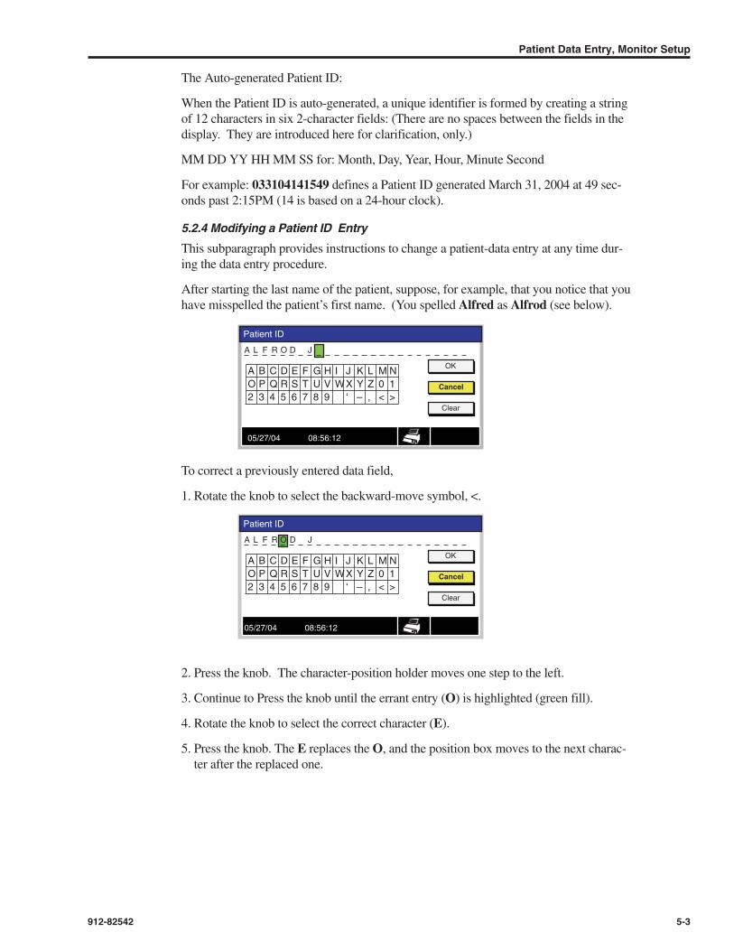
The Auto-generated Patient ID:
When the Patient ID is auto-generated, a unique identifier is formed by creating a stringof 12 characters in six 2-character fields: (There are no spaces between the fields in thedisplay. They are introduced here for clarification, only.)
MM DD YY HH MM SS for: Month, Day, Year, Hour, Minute Second
For example: 033104141549 defines a Patient ID generated March 31, 2004 at 49 sec-onds past 2:15PM (14 is based on a 24-hour clock).
5.2.4 Modifying a Patient ID Entry
This subparagraph provides instructions to change a patient-data entry at any time dur-ing the data entry procedure.
After starting the last name of the patient, suppose, for example, that you notice that youhave misspelled the patient’s first name. (You spelled Alfred as Alfrod (see below).
To correct a previously entered data field,
1. Rotate the knob to select the backward-move symbol, <.
2. Press the knob. The character-position holder moves one step to the left.
3. Continue to Press the knob until the errant entry (O) is highlighted (green fill).
4. Rotate the knob to select the correct character (E).
5. Press the knob. The E replaces the O, and the position box moves to the next charac-ter after the replaced one.
Patient Data Entry, Monitor Setup
912-82542 5-3
Patient ID
OK
L F R O D J
A B C D E F G H I J K L M NO P Q R S T U V WX Y Z 0 12 3 4 5 6 7 8 9 ‘ – , < >
Cancel
Clear
A
05/27/04 08:56:12
Patient ID
OK
L F R J
A B C D E F G H I J K L M NO P Q R S T U V WX Y Z 0 12 3 4 5 6 7 8 9 ‘ – , < >
Cancel
Clear
A DO
05/27/04 08:56:12

You may now repeat the alphanumeric character selections from that point forward, orRotate the knob to select the right-moving control character >. Then, by successivePressures of the knob advance the position to the appropriate place for continued dataentry.
NOTE
If a number of character entries require changing, it may be more convenient toClear all prior entries and start anew.
5.2.5 Completing the Patient Data Entry Process
It is necessary to insert relevant values into the six (6) patient physiological characteris-tics before the Operator can leave the Patient Data Menu. The Operator has two (2)choices: Either
• Reuse Last Patient data, (Selecting the data from the last patient (Rotating and Pressingthe knob) fills the six boxes. The Patient ID is not changed.)
Or
Insert entries into each of the six boxes.
To start the monitoring process:
1. Rotate the knob to highlight Return.
2. Press the knob. The screen now displays the main configuration with no measurementinformation inserted (Figure 5-3).
5.3 Patient Data Entry During Monitoring SessionAs indicated earlier, the LIFEGARD ICG Operator may access the Patient Data menusat any time during the monitor’s use. This is initiated through the STATUS frame menuoptions.
Caution
Whenever the Patient Data Menu is invoked, a new patient record is established inthe monitor.
Caution
The monitor stores a maximum of 100 records or 12 hours of trending data.
When either limit (100 records or 12 hours) is reached, additional records over-write the first ones.
LIFEGARD ICG Operator’s Manual
5-4 912-82542
Patient ID
OK
L F R J
A B C D F G H I J K L M NO P Q R S T U V WX Y Z 0 12 3 4 5 6 7 8 9 ‘ – , < >
Cancel
Clear
A DE
E
05/27/04 08:56:12

Figure 5-2. Pointing to the Status Frame
5.3.1 Accessing the Status Frame Menu
1. Rotate the navigation knob to highlight the Status Frame. See Figure 5-2.
2. Press the knob to display the first-level menu of the frame. See Figure 5-3.
Figure 5-3. First-Level Menu of the Status Frame
3. Rotate the knob to highlight the Patient Data Menu.
4. Press the knob. The screen displays the menu of Figure 5-1.
5.4 Time/Date ValuesAs shown in Figure 5-3, the LIFEGARD ICG Operator accesses the menu for Time andDate modifications via the Status Menu; the third option in the menu.
1. Rotate the knob to highlight the Time/Date Menu option.
2. Push the knob. The screen now displays the Time and Date Menu seen in Figure 5-4.
Figure 5-4. Time/Date Menu
Patient Data Entry, Monitor Setup
912-82542 5-5
CI
mmHg 160
ICG
05/27/04 08:56:12
l/min/m2
1.0 W/scm
1.0 mVcm
vECG
TFC 28
2.4 71
Status Menu
Setup Menu
Patient Data Menu
Time/Date Menu
Return
05/27/04 08:56:12
Time/Date Menu
09 :
Cancel
Time 46 : 45
05Date 28 04
MM / DD / YYDate Format
Set
05/27/04 08:56:12

To modify any setting:
1. Rotate the knob to highlight the field to be changed (filling with a yellow back-ground) and then
2. Press the knob (changing the fill to a green background).
Subsequent knob rotations will change the value in the green-background area. To select(latch) a displayed value, press the knob. The background reverts to yellow.
Table 5-1 describes the order of frame selection. Clockwise knob rotations descendthrough the list. Counterclockwise rotations ascend the list.
Table 5-1. Time/Date Menu Values
Changing the Date Format enables the Operator to use a date sequence of MM.DD.YYinstead of the factory-set default of DD/MM/YY.
Pressing the knob after Rotating to highlight Set or Cancel causes the previously activescreen to be displayed.
The CO, Heart Rate, NIBP, Status, Battery frames, and printer icon are updated normal-ly while the Time/Date Menu is displayed.
5.5 Monitor SetupThe Status Menu provides the capability for setting or modifying selectable factory setdefaults via a next level Setup Menu.
NOTE
Changes made by the Operator will remain until the monitor is returned to theSTANDBY power mode. Default values are restored when the monitor is nextturned to ON.
Qualified personnel may use password-controlled menus to modify default valuesthat will remain through subsequent power ON/STANDBY cycles until reset byqualified personnel.
LIFEGARD ICG Operator’s Manual
5-6 912-82542
Hour
Min
Sec
Month or Day depending on Date Format
Year
Date Format
Set or Cancel

To access this menu:
1. Rotate the navigation knob to highlight the Setup Menu in the Status Menu display.See Figure 5-5
Figure 5-5. The Setup Menu in the Status Menu Display
2. Press the knob. The Setup Menu is displayed. See Figure 5-6.
Figure 5-6. The Setup Menu
As indicated in Figure 5-6, the Setup Menu provides five options.
• To select the Power Up Defaults menu,
• To select the Service menu,
• To select Demo Mode,
• To select Print On Alarm (Default is OFF)
• To Return to the previous screen
NOTE
Access to the Power-Up Defaults, Service and Demo menus are accessible onlyto personnel who have the appropriate passwords. If selected, the appropriatepassword entry window will be displayed.
NOTE
The CO, Heart Rate, NIBP, Status Battery frames and printer icon are updatednormally while the Setup Menu is displayed.
5.6 Print On AlarmThe menu of Figure 5-6 includes an option to enable the Print-On-Alarm function bychanging the Off state to ON.
The procedure for accomplishing this, and for details about the printed record areincluded in Chapter 9 Recording/Printing.
Patient Data Entry, Monitor Setup
912-82542 5-7
Status Menu
Setup Menu
Patient Data Menu
Time/Date Menu
Return
05/27/04 08:56:12
Setup Menu
Power Up Defaults Menu
Service Menu
Demo Mode
ReturnPrint On Alarm Off
05/27/04 08:56:12
6.1 GeneralThis chapter provides Operator instructions for LIFEGARD ICG monitoring Non-Invasive Blood Pressure. It includes preparation of the patient, selecting the mode ofNIBP measurement, configuring the displays, setting alarm limits, and obtaining select-ed recording of monitored data.
LIFEGARD ICG NIBP monitoring uses a stepped oscillometric measuring technique.A motorized pump inflates the cuff until the flow of blood is practically occluded. Thepressure is then bled in steps, and blood begins to flow. A pressure transducer measuresthe changing air pressure. The pressure at which the oscillation increases sharply isdefined as the systolic pressure. The pressure at which the oscillations peak is definedas the mean arterial pressure, and the point at which a loss of oscillations is detected isdefined as the diastolic pressure.
6.1.1 Required Accessories
NIBP Cuff — There are three cuffs available for different sized patients. (See Table 6-2below)
NIBP Hose
6.1.2 Applying Cuff to Patient
Caution
Use only Analogic approved pressure tubing and cuffs. Using other cuffs or tubingmay result in inaccuracies.
WARNING
Do not use the Analogic LIFEGARD ICG to monitor patients who are linked toheart/lung machines.
WARNING
The Analogic LIFEGARD ICG may not operate effectively on patients who areexperiencing convulsions or tremors.
Caution
Inaccurate measurements may be caused by
• Incorrect cuff application or use, such as placing cuff too loosely on patient, usingthe incorrect cuff size, or not placing cuff at the same level as the heart.
• Leaky cuff or tubing
• Excessive patient motion.
WARNING
Continuous cuff measurements (Prolonged impairment of circulation) can causeinjury to patient being monitored. Consider the use of the STAT Mode of NIBPmonitoring.
NIBP Monitoring
912-82542 6-1
6NIBP Monitoring

LIFEGARD ICG Operator’s Manual
6-2 912-82542
CautionEnsure that there are no kinks in the air hose, or that the flow of air is not impededby the placement of any object that might constrict the air hose.
CautionThe LIFEGARD ICG monitor automatically retries if the initial cuff pressure is lessthan the patient Systolic pressure. The subsequent initial pressure is increased by 30 mmhg. There is a time-out period at which time the monitor stops trying toget readings. If the patient’s systolic pressure is known to be extremely high it isrecommended that the initial cuff pressure be raised to 240 mmHg.
NOTEThe cuff may remain in place when using defibrillator equipment.
NOTEThe NIBP cuff and hose will not be affected by wetting.
Measure the patient’s limb and select the proper size cuff (Table 6-1). The cuff widthshould span approximately two-thirds of the distance between the patient’s elbow andshoulder. Follow Directions for Use for applying cuff to arm or thigh.
Table 6-1. Cuff Sizes
WARNING
Those products in Table 6-1 that contain natural rubber latex may cause allergicreactions.
Setup Connections
Instructions for Cuff Use
1. Remove the cuff from its package. Inspect for damage before each use. Do not use acuff whose structural integrity is suspect.
2. Connect one end of an AN4K-AC015 or AN4K-AC019 hose to the monitor connec-tor as described.
3. To connect the hose to the cuff, grasp both connectors, align, and push together. Theconnectors will snap into place. A
A
AN4K-AC015/AN4K-AC019
Order Code Description Arm Circumference (range)
AN4K-AC013 Small Adult–Latex 180 mm to 260 mm
AN4K-AC012 Adult–Latex 250 mm to 350 mm
AN4K-AC011 Adult Plus–Latex 330 mm to 470 mm
AN4K-AC018 Small Adult–Non-Latex 180 mm to 260 mm
AN4K-AC017 Adult–Non-Latex 250 mm to 350 mm
AN4K-AC016 Adult Plus–Non-Latex 330 mm to 470 mm

4. Squeeze all the air out of the cuff and wrap it around the patient’s upper arm. Foradult and pediatric patients, the arm is the preferred location. When the arm cannot beused, the ankle is preferred over the thigh because measurement on the adult thightends to be uncomfortable.
5. Position the cuff so that the symbol is directly over the patient’s artery. Thetension of the wrapped cuff should be such that only two fingers can be insertedbetween the limb and the cuff. If the cuff is wrapped too loosely, errors may occurduring measurement.
Note: Analogic supplied blood pressure cuffs have a double-headed arrow between twolines to indicate proper size range. The edge of the cuff has a white index line (a).If the index line does not fall between the two range lines when the cuff is wrappedaround the patient’s limb, select a larger or smaller cuff size.
Removal/Cleaning
To remove the cuff from the hose, grasp the hose connector and pull back the outermetal ring at the end of the connector.
The cuffs are intended for reuse and may be cleaned by wirping with a cleaning agentsuch as 70% isopropyl alcohol.
Caution
Federal law (U.S.) restricts this device to sale by or on the order of a physician.
6.2 Measuring Blood Pressure
6.2.1 Three Modes
Blood Pressure can be measured in three modes:
• Single: In which one measurement of each of the three blood pressures (Systolic/MeanArterial Pressure/Diastolic) is made and displayed in the NIBP Frame.
• Automatic: In which measurements are made in preset intervals.
• STAT: In which as many measurements as possible are made within a 5-minute period.
6.2.2 NIBP Measurement Setup
The LIFEGARD ICG provides the capability for the Operator to modify the factory-setinitial 160-mmHg value of pump pressure that is intended to occlude blood flow in anadult patient. Operator adjustment of this value is accomplished with the NavigationKnob within the NIBP Menu.
To access the NIBP menu
1. Rotate the navigation knob to select (magenta border around the parameter box) theNIBP Frame.
2. Press the knob. The NIBP Menu is displayed in the Graphical Frame (Figure 6-1).
NIBP Monitoring
912-82542 6-3
B
B
A
C
C

LIFEGARD ICG Operator’s Manual
6-4
Figure 6-1. Accessing the NIBP First-Level Menu
Note that the displayed options include the monitoring mode selection, the alarm setting,and the initial cuff inflation value setting. Figure 6-1 indicates that the systolic upperalarm limit parameter has already been highlighted and selected (green fill). It also indi-cates that the factory-set initial cuff pressurization has been changed to 140 mmHg.
To modify the systolic upper alarm limit:
1. Rotate the navigation knob clockwise to increment the value, or counterclockwise todecrement the value.
2. Press the knob to latch the modified value in the monitor memory when the desiredpressure value is displayed by rotating the knob.
Use the sequence pair of Rotate and Press to highlight, select, modify, and latch the newvalues for the remaining five (5) alarm limit settings.
To enable/disable the audio and visual alarm:
In the parameter frame, use the Navigation Knob to highlight and select the triangle andthen, to scroll, toggle the On/Off states of the triangle icon.
• Press the knob. The state of the audible alarm is toggled from On to Off to On, etc.
To modify the Initial Inflation Pressure:
1. Rotate the navigation knob to highlight (yellow fill) the boxed value of the presentlyset pressure.
2. Press the knob. The value box has a green-fill background.
3. Rotate the knob to change the initial pressure value.
4. Press the knob when the desired value is displayed.
NOTE
The monitor will increase the initial pressure in 30-mmHg steps automatically if theinitial value does not occlude the flow of blood. The monitor initiates a new bloodpressure test with the changed value.
The incremental increases of initial cuff pressure continue until a maximum allow-able value is reached or a valid measurement is obtained. At that time, the mes-sage “NIBP-Overpressure” is displayed.
NOTE
If an attempt is made to modify the initial inflation pressure during a measurement,the new entry will be ignored.
912-82542
NIBP Menu
Automatic Mode Interval Off
Initial Inflation Pressure 140
SYS
200
Return
MAP
150
DIA
100
130 100 80
CO
l/min 6.2 105mmHg
Battery Low
183/107 (149)17
NIBP Menu Frame.Only fields within thisframe are selectable.

If you wish to use the Single measurement mode, you are now ready to initiate theNIBP measurements via the front-panel keypad NIBP button.
A momentary press on the NIBP button initiates the Single measurement mode.
NOTE
If the time between the initiation of a blood-pressure measurement and its comple-tion is prolonged (indicating an impairment of the function), the monitor ends themeasurement mode and displays an error message NIBP TIME OUT in the statusframe.
To enable Automatic Mode NIBP measurement:
1. Rotate the navigation knob to highlight (yellow fill) the Automatic Mode Intervalparameter.
2. Press the knob. The value box has a green fill.
3. Rotate the knob to scroll through the selectable values (See Table 6-2)
4. Press the knob to latch the desired value. This initiates the Automatic Mode at theinterval selected. Selecting Off removes that mode and returns control to the front-panel keypad.
NOTE
You must exit the menu in order to initiate the selected Automatic Mode. The firstmeasurement is made upon exiting the setup menu.
NOTE
If automatic mode has been selected as the institutional default, initiating ameasurement after power-on requires a NIBP key-pad button press.
Table 6-2. NIBP Automatic Mode Interval OptionsMaintaining pressure on the keypad button for more than 2 seconds initiates STAT modein which as many readings as possible are taken over a 5-minute period.
6.3 Operator Troubleshooting
6.3.1 Testing the Out-of-Limits Measurement Alarm Response
This test is performed by forcing an out-of-limits alarm condition and noting the moni-tor’s response.
NIBP Monitoring
912-82542 6-5
Off
1 min
2 min
3 min
5 min
10 min
15 min
30 min
60 min
90 min

Table 6-3. Testing the Alarm Limits Function
6.3.2 Testing the Faulty-Air-Hose Alarm Response
Table 6-4. Testing No-Cuff Alarm Function
Table 6-5. Testing Cuff-Inflation Alarm Function
LIFEGARD ICG Operator’s Manual
6-6 912-82542
Step Action
1 Using Table 6-1, obtain the proper size cuff for the operator’s arm, assum-ing that the operator is a healthy person.
2 Attach the NIBP cable to the cuff and to the air valve in the rear panel ofthe monitor.
3 Following standard institutional procedures, apply the cuff to the arm.
4 Press the front-panel NIBP button to start the blood pressuremeasurement
5 When a measured value is displayed, note the systolic value.
6 Using the procedure described in paragraph 6.2.2, adjust the value of sys-tolic (SYS) alarm upper limit at least 10 points below the observedmeasurement.
7 Repeat Step 4, above. An alarm condition should be generated if the newsystolic value is above the new limit. If the systolic value is below the limit,lower the limit another 20 units and repeat step 4. Verify that the audiblealarm is sounded, that the NIBP frame fill color is changed, and that theNIBP frame blinks as specified for a visual alarm.
8 Reset the SYS upper alarm limit to its initial value.
Step Action
1 Connect cuff air hose cable to monitor valve.
2 Press front-panel NIBP button to start the blood pressure measurement.Observe the attempt to inflate the cuff to the initial pressure value.
3 Disconnect the air hose from the monitor.
4 Check for specified monitor’s responses to the alarm condition: displaychanges the background fill color in the NIBP frame; a no-signal display ofdashes appears in place of any numerals; and a warning message NIBPNO CUFF appears in the status frame.
Step Action
1 Connect cuff air hose cable to monitor valve.
2 Press front-panel NIBP button to start the blood pressure measurement.Note the attempt to inflate the cuff to the initial pressure value.
3 Bend air hose sufficiently to occlude any air passage.
4 Check for specified monitor’s responses to the alarm condition: displaychanges the background fill color in the NIBP frame; a no-signal display ofdashes appears in place of any numerals; and a warning message NIBPBLOCKED HOSE appears in the status frame.

CO and ECG Monitoring Mode
912-82542 7-1
7CO and ECG Monitoring Mode
7.1 General This chapter provides Operator instructions for LIFEGARD ICG monitoring of Non-Invasive Cardiac Output (CO). It includes preparation of the patient, selecting the modeof measurement, and configuring the Cardiac Output (CO) and ECG frame display.Detailed descriptions of graphical and tabular CO and ECG trend displays and configur-ing CO and ECG data in the all data display are included in Chapter 8; setting alarmlimits in Chapter 4; and obtaining selected recording of monitored data in Chapter 9.
WARNING
Observe all safety precautions concerning the use of attachments to patients.Review the safety concerns detailed in Chapter 2, and heed all WARNINGS andCAUTIONS.
7.2 Patient PreparationICG mode is intended for use on patients whose weight and height are within specifiedlimits as indicated below.
• Height: 4 ft - 7 ft-6 in (122 - 229 cm)
• Weight: 67 - 350 lb (30 - 159 kg)
Values may not be accurate if the patient’s height and weight are outside these limits.
Caution
The following conditions may reduce the accuracy of data provided by ICG modeoperation:
• Patients with aortic valve regurgitation.
• Patients who are linked to a cardiopulmonary bypass machine.
• Patients with severe sustained arrhythmias.
• Patients who are on an intra-aortic balloon pump or chest tubes.
• Patients with anemia.
• Patients who have congenital heart defects.
• Patients on a ventilator.
• Patients with pericardial effusion.
• Where there are distortions in the anatomy of the area where sensors areplaced.
7.2.1 Required Accessories
LIFEGARD ICG Patient Cable: Analogic Part # 21-00122-01
Four (4) LIFEGARD ICG Dual Electrodes: Analogic Part # 21-000317-01

WARNING
Conductive parts of electrodes and associated connectors for applied parts, andneutral electrode should not contact other conductive parts and earth.
NOTE
The LIFEGARD ICG Patient Cable is used for both patient monitoring modes: ICGand ECG.
7.2.2 Attaching Electrodes
NOTE
If electrodes and patient cable have been attached and connected to the monitor,Paragraph 7.2.2 may be skipped.
The LIFEGARD ICG monitor requires the use of LIFEGARD™ ICG Dual Electrodesto ensure the proper spacing between current drives and current receivers for accuratemeasurement of thoracic impedance. Figure 7-1 illustrates a dual electrode with the cor-rect spacing. The LIFEGARD ICG Dual Electrodes come in packages of 4 and labeledas shown in Figure 7-2.
NOTE
Electrodes may remain in place when using defibrillator equipment.
Figure 7-1. Individual ICG Dual Electrode
Figure 7-2. ICG Dual-Electrodes, Pouch Package Label
LIFEGARD ICG Operator’s Manual
7-2 912-82542
MANUFACTURED FOR:ANALOGIC CORPORATIONLIFE CARE SYSTEMS DIVISION8 CENTENNIAL DRIVEPEABODY, MA 01960 U.S.A.Made in United States
TM
2 LATEX
LIFEGARDªICG
DUAL ELECTRODE
LIFEGARDªICG
DUAL ELECTRODE= 4 x
= 10 x
AN4700 – AC031
+1 (978) 977-3000 ext. 4700
e-mail: [email protected]
http://www.analogic.com/lcsorders
LIFEGARD ICG DUAL ELECTRODE
RXOnly
3

Figure 7-3 illustrates the dual electrodes locations relative to the rib cage.
Figure 7-3. Positioning the Four ICG Dual Electrodes
7.2.3 Attaching Patient Cable
There are 8 leads of the Patient Cable to be attached to the electrodes. Figure 7-4 identi-fies the leads and colors of the grippers.
Figure 7-4. Identifying the Function and Color Code of the 8-Lead ICG Patient Cable
CO and ECG Monitoring Mode
912-82542 7-3
Left Upper Thorax I Source
Right Upper Thorax I Source
BlueExcitation Current
Left Upper Thorax Sense
Right Upper Thorax Sense
RedICG/ECG In 1
Left Lower Thorax I Sense
Right Lower Thorax Sense
RedICG/ECG In 2
Left Lower Thorax I Source
Right Lower Thorax I Source
VioletExcitation Current Rtn
BlueRed
BlueRed
RedViolet
RedViolet

Table 7-1. Cable Attachment Procedure
Figure 7-5. LIFEGARD™ ICG Rear Panel, Patient Cable Connector at Rear Left Side of the Monitor
7.3 Monitoring Cardiac OutputUpon completion of the patient preparation, initiate the CO monitoring function by turn-ing the monitor ON. Figure 7-6 illustrates a typical main screen display. The COmeasurement is displayed in the upper left frame.
When pacer detection is turned ON, the monitor detects pacer pulses and the detectedpulse is indicated on the display by a full-scale pulse in the displayed waveform.Detected pacer pulses are ignored in the calculation of the heart rate (HR).
Electrodes may remain in place when using defibrillator equipment.
7.3.1 Configuring the CO Frame
Figure 7-6. Main Display with CO Measurement
LIFEGARD ICG Operator’s Manual
7-4 912-82542
Step Action
1 Peel off the backing of the dual electrode.
2 Using the adhesive of the dual electrode, place andattach the electrodes to the patient as indicated inFigure 7-3.
3 Attach the ICG Patient Cable grippers to the dualelectrodes.
4 Connect the ICG cable to the monitor connector atthe rear panel of the monitor (Figure 7-5).
Patient CableConnector
CO
mmHg 160
ICG
05/27/04 08:56:12
l/min
1.0 W/scm
1.0 mVcm
vECG
TFC 28
100%
4.5 71

Figure 7-6 illustrates some of the features of the display of CO.
• The frame label of CO in the frame upper left corner indicates that the displayed valueis cardiac output (CO). (A selectable option displays the cardiac index CI in thisframe,)
• The numeric measurement indicates a digitized value of 4.5, and the units are indicatedin the lower left corner of the frame as l/min (liters/minute).
• The Alarms Off icon indicates that the alarms are disabled.
The cardiac output frame may be reconfigured by operator use of menu-driven options.
To reconfigure the frame:
1. Rotate the navigation knob to highlight the CO frame (a magenta colored border“boxes” the frame).
2. Press the knob. A menu appears in the multi-use frame (Figure7-7).
Figure 7-7. CO Menu Display
The options available to the operator include those described below.
• Changing the displayed value. When the INDEX parameter is changed to On by usingthe navigation knob, the Cardiac Index (CI) will be displayed in the frame. The framelabel is changed to CI in the upper left corner, and the numeric indexed value(CO/BSA) is displayed in the frame as shown in Figure 7-8.
The selection does not change the parameter plotted in the Trend Display.
Figure 7-8. CI Selected for Cardiac Output Frame Display
CO and ECG Monitoring Mode
912-82542 7-5
CO Menu
Index
Off10.5
Return
5.5
05/27/04 08:56:12
CI
mmHg 160
ICG
05/27/04 08:56:12
l/min/m2
1.0 W/scm
1.0 mVcm
vECG
TFC 28
100%
2.5 71Label: CI
Units:l/min/m2
CInumeric

• Turning the alarms off. If an alarm condition is detected when the alarms are off,removes both audio and visual alarms.
• Setting alarm limits. The ranges of upper alarm limit and lower alarm limit are shownin the short table that follows.
Table 7-2. Ranges of Cardiac Output Alarm Limits
The monitor prevents the setting of an upper alarm limit that is lower than the value setfor the lower alarm limit. It also prevents setting a lower alarm limit that is greater thanthe value set for the upper alarm limit.
NOTE
The range of values over which the Alarm Limits can be set does not necessarilyspan the monitor’s measurement range. In those cases the Limit range covers“normal ranges.” See Appendix A.
7.4 ECG Monitoring Mode
7.4.1 General
In a typical monitoring scenario, the ICG-monitored cardiac output may be correlatedwith the patient ECG by observing the ECG waveform that is superimposed on the ICGwaveform in the Multi-use Frame, as shown previously in Figure 7-8.
The ECG Measuring Technique
Depolarization and repolarization of the myocardium generates electric potentials thatECG electrodes on the patient’s skin surface can sense. The monitor processes andamplifies these signals and presents the ECG waveform on the screen.
In addition to acquiring the QRS complex, the monitor also:
• Computes and displays the heart rate in beats per minute in the ECG numeric frame(Figure 7-8).
• Detects a leads-off condition, if one of the drive electrode connections is disrupted or ifeither the two neck or the two torso sense electrode connections are disrupted.
• Detects the presence of pacemaker signals within the waveform complex of the ECG.
• Recovers from defibrillator discharge within 16 seconds.
NOTE
The Heart Rate algorithm averages 6 of the most recent 8 detected R-R intervalsand excludes the longest and shortest of the 8 intervals. The average heart rate isthe reciprocal of the calculated average of the remaining 6 intervals.
LIFEGARD ICG Operator’s Manual
7-6 912-82542
Cardiac Output CO Index Cardiac Output CIMinimum Maximum Minimum Maximum
Upper Alarm Set 4.0 12.0 2.0 8.0
Lower Alarm Set 1.0 6.0 0.5 3.5

NOTE
The processing of the ICG signal requires that the waveform have the respirationcomponent of resistance change removed before further processing. This resultsin an 8 second delay before the waveform can be displayed. As the ECG wave-form must be presented synchronously with ICG, it also has an 8 second delayfrom real time. Therefore the waveform recovery on the screen will have thisadded to the recovery of the ECG waveform display.
NOTE
Figure 7-8, includes the vertical scale factors for the ICG and the ECG plots in thescreen. The scale value of each 1-cm vertical displacement of the ICG plot is 1.0 Ω/s (a unit of the impedance cardiograph). It is displayed in the same magen-ta color as the plot of the curve.
Each 1-cm vertical displacement of the ECG plot is 1 millivolt of the measuredpotentials.
Both scale factors are operator-configurable.
7.4.2 Configuring the ECG/ICG Waveform Display
The configuring process is accomplished by menu-driven actions.
To configure the graphical trend:
1. Rotate the navigation knob until the trend display is “boxed”.
2. Press the knob. The ECG/ICG Menu is displayed in the multi-use frame (Figure 7-9).
Figure 7-9. ECG/ICG Menu, Parameter Values are Factory-Defaults
The plotting parameters and their descriptions are identified in Table 7-3
Table 7-3. ECG/ICG Trend-Plotting Parameters
Note 1: Bold type indicates the factory-set default value.
CO and ECG Monitoring Mode
912-82542 7-7
ECG/ICG Menu
Sweep Speed 25.0 mm/s
Return
Size 1.0 mV/cm
Pacer Detect Off
05/27/04 08:56:12
Parameter Description Values (Note 1)
Sweep Speed Horizontal scale; linear 12.5, 25, cm/sdisplacement (cm) per second
Size Vertical scale; signal amplitude 0.5, 1.0, 2.4 mV/cm(mV) per cm of display
Pace Detected Inclusion (or exclusion) of Off, Onpacemaker pulse in signal

7.5 The Heart-Rate Frame in the Main DisplayFigure 7-10 illustrates the appearance of the heart-rate measurement in the Heart RateFrame (upper right corner of the main display).
Figure 7-10. ICG Main Display with Heart Rate Data in Frame
Note the following features in the Heart-Rate Frame display of Figure 7-10.
• The color of the numeric data and of the symbols in the Heart Rate Frame is the sameas the color (green) of the plotted ECG waveform in the Multi-Use Frame.
• The “heart” symbol is indicative of the parameter.
• The symbol is used to identify the ECG waveform as the source data fromwhich the heart rate is calculated. The alternate source is the NIBP measurement.When the NIBP source is used, the boxed QRS waveform symbol in the Heart RateFrame is replaced with the blood pressure symbol . The symbol is displayed inred; no other color in the frame is changed.
• The parameter alarms have been turned off, as evidenced by the “X” superimposedover the triangle symbol.
7.5.1 Configuring the Heart Rate Frame
The operator may configure the Heart-Rate Frame by using menu-driven options.
To access the menu:
1. Rotate the navigation knob to highlight (box) the Heart-Rate Frame.
2. Press the knob. The menu appears in the Multi-Use Frame (Figure 7-10 in the previ-ous paragraph).
The menu indicates the current settings of the upper and lower alarm limits. Each limitcan be modified independently. However, the monitor does not accept a lower limitgreater than the setting in effect for the upper, and, conversely, to make the upper limitless than the setting of the lower limit.
LIFEGARD ICG Operator’s Manual
7-8 912-82542
HR Menu
225
Return
60
CO
mmHg 160
l/min 4.5 71
05/27/04 08:56:12

To modify an alarm limit
1. Rotate the knob to highlight the limit to be changed; for example, the upper limit.The background “fill” of the boxed value is changed to yellow.
2. Press the knob. The fill color is changed to green.
3. Rotate the knob in a clockwise direction to increase the value; in a counterclockwisedirection to decrease the value.
4. When the desired value is shown, (e.g. 110) Press the knob. The fill color is changedto yellow (Figure 7-11).
Figure 7-11. Changed Alarm Upper Limit Setting
To return to the main display
1. Rotate the knob to highlight the Return option.
2. Press the knob. The main display screen appears in the Multi-Use Frame.
7.6 Operator Troubleshooting
7.6.1 Testing the Out-0f-Limits Measurement Alarm Response
Forcing an out-of-limits alarm condition and noting the monitor’s response perform thistest.
Table 7-4. Testing the Alarm Limits Function
CO and ECG Monitoring Mode
912-82542 7-9
HR Menu
110
Return
40
CO
mmHg 160
l/min 4.5 71
05/27/04 08:56:12
Step Action
1 Using the procedure described in paragraph 7.2, attach the electrodes to yourbody, (Assuming you are a healthy person.)
2 Attach the patient cable to the electrodes and to the rear panel of the monitor.
3 Using any one of the Cardiac Output monitoring modes, initiate the cardiac outputmeasurement by turning the monitor ON.
4 When a measured CO value is displayed in the CO frame, note its value.
5 Using the procedure described in paragraph 7.3, adjust the maximum value of theCO upper alarm setting at least 2 points below the observed measurement.
6 Repeat Step 3, above. An alarm condition should be generated. Verify that theaudible alarm is sounded, and that the CO frame fill color is changed.
7 Reset the CO upper alarm limit for the patient monitoring actions.

7.6.2 Testing the Lead-Off Alarm Function
Table 7-5. Testing Lead-Off Alarm Function
LIFEGARD ICG Operator’s Manual
7-10 912-82542
Step Action
1 If this test is being performed immediately after that of Table 7-4, above, skip tostep 2. If not, perform steps 1, 2 and 3 of the previous table.
2 After a measured value appears in the CO frame, disconnect the patient cablefrom the monitor rear panel.
3 Check the monitor for its alarm responses: the audio alarm is sounded; the back-ground fill of the CO and HR frames frame is changed to yellow; and a warningmessage ICG Leads Off is displayed in the status frame.
4 The alarm conditions remain until the condition is corrected (the leads are reconnected).

8.1 GeneralThis chapter includes a description of the configurations of the Trend and Data displaysand the menu-based procedures for obtaining them.
8.2 The Trend DisplayThe monitor’s Multi-Purpose Frame Display is used to display Trend and Data configu-rations. As described earlier in an illustration of Chapter 4, Monitor Description andreproduced below as Figure 8-1, the operator may select one of two Trend displays(Graphical or Tabular) by using the front-panel screen selection button identified inFigure 8-2.
Figure 8-1. Stepping through the Multi-Purpose Frame Display Configurations
Figure 8-2. Identifying the Front-Panel Screen Selection Button
Graphical Trend, Tabular Trend, All-Data Display
912-82542 8-1
8Graphical Trend, Tabular Trend,
All-Data Display
Main
GraphicalTrend
TabularTrend
All Data
Screen SelectionButton Press
Screen SelectionButton Press
Screen SelectionButton Press
Screen SelectionButton Press
ScreenSelectionButton
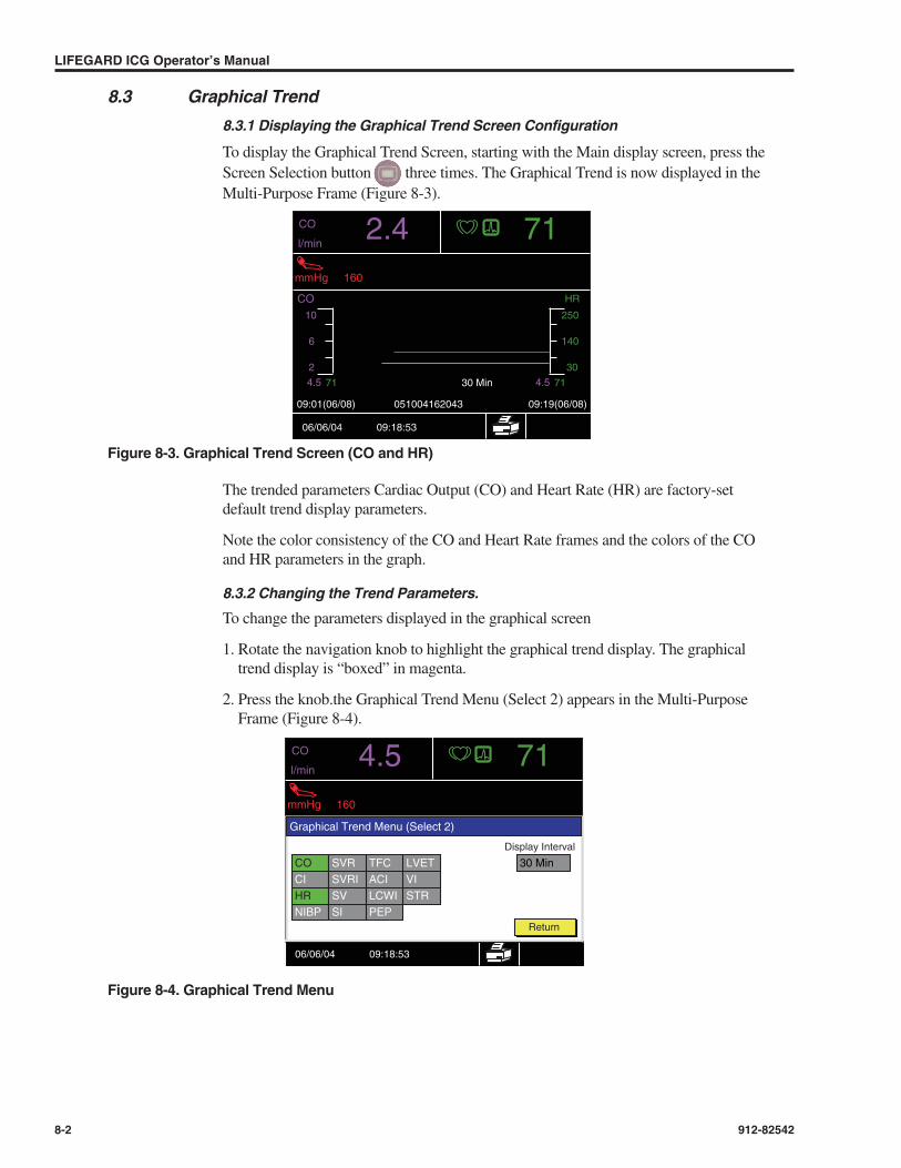
8.3 Graphical Trend
8.3.1 Displaying the Graphical Trend Screen Configuration
To display the Graphical Trend Screen, starting with the Main display screen, press theScreen Selection button three times. The Graphical Trend is now displayed in theMulti-Purpose Frame (Figure 8-3).
Figure 8-3. Graphical Trend Screen (CO and HR)
The trended parameters Cardiac Output (CO) and Heart Rate (HR) are factory-setdefault trend display parameters.
Note the color consistency of the CO and Heart Rate frames and the colors of the COand HR parameters in the graph.
8.3.2 Changing the Trend Parameters.
To change the parameters displayed in the graphical screen
1. Rotate the navigation knob to highlight the graphical trend display. The graphicaltrend display is “boxed” in magenta.
2. Press the knob.the Graphical Trend Menu (Select 2) appears in the Multi-PurposeFrame (Figure 8-4).
Figure 8-4. Graphical Trend Menu
LIFEGARD ICG Operator’s Manual
8-2 912-82542
051004162043 09:19(06/08)
HR
10
6
2
250
140
30
7130 Min
CO
mmHg 160
l/min2.4 71
CO
4.5 4.571
09:01(06/08)
06/06/04 09:18:53
CO
mmHg 160
l/min4.5 71
06/06/04 09:18:53
Display Interval
Graphical Trend Menu (Select 2)
Return
CO SVR TFC LVETCI SVRI ACI VIHR SV LCWI STRNIBP SI PEP
30 Min

This menu includes the fifteen (15) parameters from which two (2) may be selected forthe monitor to plot in the graphical trend display. The current parameters are highlightedin the menu by the distinct green color, while the other thirteen are grayed.
Note that this menu also includes an opportunity to set up the x-axis time scale (DisplayInterval). The current interval is the factory-set default of 30 minutes (30 Min).
To change the plotted parameters, consider replacing the CO parameter with the CIparameter. First remove the ones you no longer need.
1. Rotate the knob to highlight the CO parameter. The parameter name is displayed inyellow within the green box.
2. Press the knob. The box background color changes to gray, but the CO label remainshighlighted to yellow to indicate the current location of the knob “pointer.”
3. Rotate the knob to highlight the replacement parameter (CI). The label CI is now dis-played in the yellow highlighted color, which the color is removed from the CO label.
4. Press the knob. The new parameter is selected. Its “box” is now filled with the greencolor.
Before returning to the new plot, you may want to change the x-axis time interval.However, if you want to retain the 30-minute interval, use the navigation knob to high-light and select Return in the menu. The new plot with the previously set time interval isshown in Figure 8-5.
Graphical Trend, Tabular Trend, All-Data Display
912-82542 8-3
CO SVR TFC LVETCI SVRI ACI VIHR SV LCWI STRNIBP SI PEP
CO SVR TFC LVETCI SVRI ACI VIHR SV LCWI STRNIBP SI PEP
CO SVR TFC LVETCI SVRI ACI VIHR SV LCWI STRNIBP SI PEP
CO SVR TFC LVETCI SVRI ACI VIHR SV LCWI STRNIBP SI PEP

Figure 8-5. Plot with Changed Parameters (CI in place of CO)
If we wish to change the x-axis time interval, three (3) time interval options are available
• 30 minutes (Factory-set default), or
• 2 hours, or
• 4 hours.
To change the time interval value:
1. Rotate knob to highlight the display interval box (see Figure 8-4).
2. Press the knob. The value box fill color changes to green and the current x-axis timeinterval is the value currently in effect.
3. Rotate the knob to display either the 2- or 4-hour time value.
4. Press the knob to select the desired displayed value (e.g., 2 hours).
5. Rotate and press the knob to highlight and select Return on the menu.
The new screen display (Figure 8-6) indicates:
• The changed x-axis time interval (2 hours), and
• The changed y-axis label (CI).
LIFEGARD ICG Operator’s Manual
8-4 912-82542
051004162043 09:19(06/08)
HR
10
6
2
250
140
30
7130 Min
CI
mmHg 160
l/min/m22.4 71
CI
2.4 2.471
09:01(06/08)
06/06/04 09:18:53
Display Interval
30 Min
Display Interval
2 hours

Figure 8-6. Plotting CI Parameter and Changed X-Axis Time Interval
8.3.3 Scrolling the Trend Screen
The scrolling action provides the capability to examine stored Graphical Trend signalswithin the time interval currently selected.
To activate the trend capability while displaying the Graphic Trend, press the front-panel scroll button.
Figure 8-7. Graphical Trend Scroll Function (30 Min X-Axis Interval)
A blue-colored bar with arrow-headed pointers at each end is centered above the plot toindicate that scrolling forward or backward in time is now possible.
Rotate the knob to scroll in either direction while examining the changing plot in thegraphical frame.
Note that the double-headed blue bar remains centered on the screen while scrollingaction takes place.
Press the front-panel scroll button again to terminate scrolling. The action togglesthe mode to OFF.
Graphical Trend, Tabular Trend, All-Data Display
912-82542 8-5
051004162043 09:19(06/08)
HR
10
6
2
250
140
30
712 hours
CI
mmHg 160
l/min/m22.4 71
CI
2.4 2.471
09:01(06/08)
06/06/04 09:18:53
051004162043 09:19(06/08)
HR
10
6
2
250
140
30
712 hours
CI
mmHg 160
l/min/m22.4 71
CI
2.4 2.471
09:01(06/08)
06/06/04 09:18:53
ScrollBarSymbol

8.4 Tabular Trend
8.4.1 To Display the Trend Data Values Stored in Memory
Press the front-panel screen selection button twice (starting from a main screen display).A tabular listing of the data values appears in the Multi-Purpose Frame (Figure 8-8).
Figure 8-8. Tabular Trend Display
8.4.2 To Scroll the Tabular Trend Data
The data list of Figure 8-8 identifies four (4) data points, stored in 1-minute intervals.Remaining data point values may be displayed by scrolling action.
To enable scroll action:
Press the front-panel scroll button .
The blue-colored scroll symbol appears in the frame.
To scroll the tabular trend data, rotate the navigation knob clockwise to go forward intime and counterclockwise to go backwards in time.
Press the front-panel scroll button again to terminate scrolling.
8.4.3 Selecting Data Parameters for Tabular Trend Display
As shown in Figure 8-9, up to eight (8) parameters may be displayed at one time in theframe. These are selected from among seventeen (17) monitored/calculated parametersavailable for display.
1. Rotate the navigation knob to highlight (box) the tabular trend display.
2. Press the knob. The Tabular Trend Menu (Select 8) appears in the frame (Figure 8-9).
LIFEGARD ICG Operator’s Manual
8-6 912-82542
06/08 051004162043 1/4
Time CO HR BP-S BP-D MAP SVR SVRI SV
14:49 4.5 71 64
14:50 4.5 71 64
14:51 4.5 71 64
14:52 4.5 71 64
CO
mmHg 160
l/min/4.5 71
06/08/04 13:12:03
06/08 051004162043 1/4Scroll-Action-EnabledIndicator

Figure 8-9. The Tabular Trend Menu
To change the tabulated parameter values, use the navigation knob and follow the proce-dure described earlier in this chapter. This involves a 2-step procedure as describedbelow.
Removing one or more unwanted parameters from the list; and selecting any desirednew parameters.
NOTE
Parameters to be displayed in the tabular Trend listing do not affect those dis-played in the Graphical Trend plot.
The menu of Figure 8-9 may be used to change the time interval between selected datavalues. The options are either 1-minute or 15-minute intervals. Figure 8-8 illustrates a 1-minute interval listing. Figure 8-10 illustrates a 15-minute interval between values.
Figure 8-10. Tabular Trend at 15-Minute Intervals
Any NIBP measurement value made within the selected interval will be replaced in theTabular Trend display.
Caution
The monitor stores a maximum of 100 records or 12 hours of trending data. Wheneither limit (100 records or 12 hours) is reached, additional records overwrite thefirst ones.
Graphical Trend, Tabular Trend, All-Data Display
912-82542 8-7
CO
mmHg 160
l/min4.5 71
06/08/04 13:12:03
Tabular Trend Menu (Select 8)
Return
CO LCWICI SI PEPHR TFC LVET
ACI
1 MinBP-D SV STRMAPSVR
BP-S SVRI VI
06/08 051004162043 1/4
Time CO HR BP-S BP-D MAP SVR SVRI SV
10:55 4.5 71 64
11:10 4.5 71 64
11:25 4.5 71 64
11:40 4.5 71 64
CO
mmHg 160
l/min/4.5 71
06/08/04 13:12:03

Caution
Trend records are displayed at intervals of 1 minute or 15 minutes. If NIBP mea-surements were obtained between the intervals they will be displayed and the nexttrend sample for display will be one interval length from the trend sample whereNIBP was obtained.
8.5 The All Data Screen
8.5.1 Screen Description
The All-Data Screen display, as shown in Figure 8-11, shows the values of up to thirteenparameters measured or calculated by the monitor.
Figure 8-11. An All-Data Screen Display
Eight of eleven selectable parameters are displayed in tabular format in the multi-pur-pose frame. Characteristics of the values displayed in this frame are described below.
• These parameters are not alarmable.
• Parameters are displayed in order of priority with the highest priority parameter beingdisplayed in the upper left sub frame of the multi-purpose frame. The next highest pri-ority parameter is displayed in upper right sub frame. This pattern is repeated for eachsubsequent row of the display.
• Parameter priorities are fixed and are determined by the order specified in the All DataMenu.
• A mnemonic and unit of measure are displayed for each parameter.
• An elapsed time icon is displayed for SVR, SVRI, and LCWI because these parame-ters are derived from MAP.
• The SVR, SVRI, and LCWI parameters will be replaced with blanks when more than60 minutes has elapsed since the last NIBP measurement.
• Individual parameters within the multi-purpose frame region are not individuallyselectable.
8.5.2 Configuring the All-Data Display
To select the parameters displayed in this frame:
1. Rotate the knob to highlight the multi-purpose frame.
2. Press the knob to display the All Data Menu.
LIFEGARD ICG Operator’s Manual
8-8 912-82542
CO
mmHg 160
l/min/4.5 71
06/08/04 13:12:03
SVRdyn s/cm5
SVml
TFC1/kOhm
LCWIkg m/m2
SVRIdyn s m2/cm5
SIml/m2
ACI1/100 s2
PEPmsec
6428
355378

Figure 8-12. The All Data Menu (Select 8)
As shown in Figure 8-12, the eight (8) parameters currently displayed are in boxes witha green fill. The other 3 possible selections are in gray-filled boxes.
To change a parameter, one of the eight must first be deselected. To deselect a parameter(SVRI, for example):
1. Rotate the knob to the desired parameter box. The parameter name in that box is high-lighted (yellow), as shown in Figure 8-12.
2. Press the knob. The parameter box is grayed. The parameter has been deselected.
3. Rotate the knob to the desired replacement parameter. The value in that box is high-lighted (yellow).
4. Press the knob. The new parameter has been selected for display.
5. Rotate the knob to Return.
6. Press the knob. The screen display now has the new group of eight parameters.
NOTE
The CO, Heart Rate, NIBP, Status and Battery frames are updated normally whilethe All Data Menu is displayed.
Graphical Trend, Tabular Trend, All-Data Display
912-82542 8-9
CO
mmHg 160
l/min/4.5 71
06/08/04 13:12:03
All Data Menu (Select 8)
Return
SVRSVRISVSI
TFCACILCWIPEP
LVETVISTR

9.1 GeneralThe LIFEGARD ICG monitor includes an integral thermo strip chart recorder operatingunder software control. The printer icon in the main screen display shown in Figure 9-1indicates the status of the printer. This chapter also includes instructions for replacingthe paper roll in the recorder.
Figure 9-1. Printer Status Display Icon
Five report types can be printed.
• Print-On-Alarm
• ICG/ECG Snapshot
• All-Data Report
• Tabular Trend Report
• Graphical Trend Report
The Print-On-Alarm report, if enabled, is activated whenever an alarm condition isdetected, and the printer is not printing an alarm report. Its content and format are pre-set in the monitor.
Printing the other reports is activated by Operator pressure on the front-panel button(Figure 9-2). Their contents are determined by the screen display. Refer to Chapter 4for screen descriptions.
Each type of report contains the same header information.
• Report Type (see above),
• Date and Time, and
• Patient Data (ID, Name, Gender, Age, Weight, Height, CVP, BSA, and PAOP)
Recording, Printing
912-82542V00R00 9-1
9Recording, Printing
CI
mmHg 160
ICG
05/27/04 08:56:12
l/min/m2
1.0 W/scm
1.0 mVcm
vECG
TFC 28
100%
2.4 71
PrinterIcon
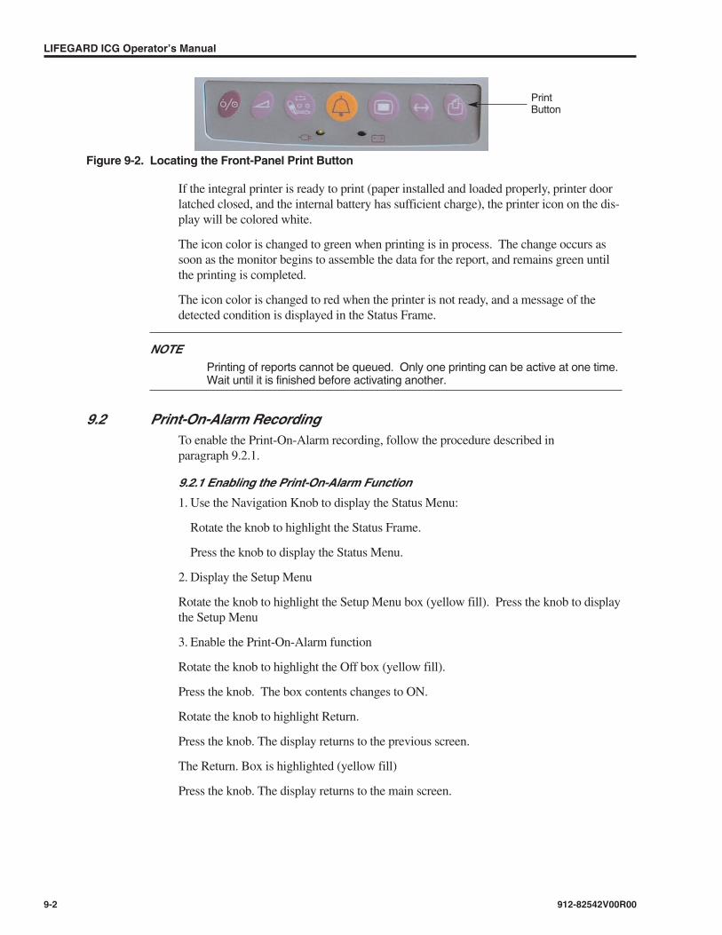
Figure 9-2. Locating the Front-Panel Print Button
If the integral printer is ready to print (paper installed and loaded properly, printer doorlatched closed, and the internal battery has sufficient charge), the printer icon on the dis-play will be colored white.
The icon color is changed to green when printing is in process. The change occurs assoon as the monitor begins to assemble the data for the report, and remains green untilthe printing is completed.
The icon color is changed to red when the printer is not ready, and a message of thedetected condition is displayed in the Status Frame.
NOTEPrinting of reports cannot be queued. Only one printing can be active at one time.Wait until it is finished before activating another.
9.2 Print-On-Alarm RecordingTo enable the Print-On-Alarm recording, follow the procedure described in paragraph 9.2.1.
9.2.1 Enabling the Print-On-Alarm Function
1. Use the Navigation Knob to display the Status Menu:
Rotate the knob to highlight the Status Frame.
Press the knob to display the Status Menu.
2. Display the Setup Menu
Rotate the knob to highlight the Setup Menu box (yellow fill). Press the knob to displaythe Setup Menu
3. Enable the Print-On-Alarm function
Rotate the knob to highlight the Off box (yellow fill).
Press the knob. The box contents changes to ON.
Rotate the knob to highlight Return.
Press the knob. The display returns to the previous screen.
The Return. Box is highlighted (yellow fill)
Press the knob. The display returns to the main screen.
LIFEGARD ICG Operator’s Manual
9-2 912-82542V00R00
PrintButton

9.2.2 The Print-On-Alarm Report
Once enabled, the monitor will print a report as illustrated in Figure 9-3. Features of thereport are listed below.
• Numeric printout of all calculated values at the time when alarm was initially detected.
• Parameter(s) in alarm are enclosed in triangular brackets <XXX>.
• Normal range of values are printed to the right of the measured value and enclosed insquare brackets [xxx].
• Time and Date of last NIBP measurement. No NIBP measurements older than onehour are printed.
• A plot of the SQF waveform.
• Waveform sweep speed (12.5 or 25 mm/s) as currently set in the waveform menu.
• Waveform vertical scaling (0.5,1,2 or 4 mV/cm for ECG and Ω/cm for ICG))
• An 8-second waveform plot of both ICG and ECG when sweep-speed is set at 25mm/sec. The waveform is printed from buffered data such that the printed waveformstarts 4 seconds before the alarm condition occurred.
• A 16-second waveform plot of both ICG and ECG when sweep-speed is set at 12.5mm/sec. The printed waveform starts 8 seconds before the alarm condition occurred.
• Dashed bars are displayed every second in the ECG and ICG waveform. A time anddate stamp is displayed every 3 seconds
If pacer detect is enabled, pacer markers are represented on the printout as a full scale,positive-going pulse.
NOTEIf the Print-On-Alarm is activated, it will preempt any other printing that may beactive.
NOTEThe monitor prints print-on-alarm reports until the alarm-causing condition is cor-rected. Perform corrective action as soon as possible in order to avoid excessiveprint paper use.
Figure 9-3. A Print-On-Alarm Report
Recording, Printing
912-82542V00R00 9-3
Print On Alarm Report
ID SIMULATION SV 64 ml [30 - 120]
CO <4.5> l/min [ 3.0 - 10.0] SI 35 ml/m2 [30-65]
Gender Male CI 2.4 l/min/m2 [2.8 - 4.2] TFC 28 1/kOhm [21 - 50]
Weight 70 kg HR 71 /min [60 - 100] ACI 53 1/100 x2 [60 -150]
Height 175 cm BP-S 125 mmHg [110 - 140] LCM 2.93 kg m/m2 [3.3 - 5.3] ICG
Age 50 yr BP-D 81 mmHg [55 - 90] PEP 79 ms [40 -100] 1.0 Ohm/s/cm
CVP 3 mmHg MAP 90 mmHg [84 - 100] LVET 282 ms [200 - 350]
PAOP 7 mmHg SVR 1540 dyn s/cm5 [770 - 1560] VI 35 1/1000s [33 - 75]
BSA 1.85 m2 SVRI 2850 dyn s m2/cm5 [1340 - 2480] STR 28 % [15 - 45]
Printed 02/23/2005 16:25:15 Last NIBP at (02/23/2005 16:22:08) 25 mm/s

NOTEThe first column contains patient information common to all reports. A graphic isincluded, indicative of the signal quality by superimposing the ICG portions of validbeats in the last 30 seconds. The graphic contains the displacement of verticalaxis sensitivity (1 mV/cm) and of horizontal sensitivity (25 mm/sec).
9.3 Print ICG/ECG Snapshot Report
9.3.1 General
At any time that the Main screen is displayed, the Operator can print a snapshot reportof the ICG/ECG plot by pressing the front-panel print button.
Figure 9-4. ICG/ECG Snapshot Report
9.3.2 The ICG/ECG Snapshot Report
As shown below in Figure 9-4, the snapshot consists of an 15-second record at 25 mm/secof the ICG/ECG plots printed on two 8.5-inch strips. (A 30-second record at 12.5 mm/sec.)In addition, Figure 9-4 includes time and date stamps along the horizontal axis.
9.4 Print All-Data Report
9.4.1 General
At any time that the All-Data screen is displayed, the Operator can print a report of theall-data record by pressing the front-panel print button.
Figure 9-5. ALL-DATA REPORT Sample Record
LIFEGARD ICG Operator’s Manual
9-4 912-82542V00R00
Print All Data ReportID SIMULATION
SV 64 ml [30 - 120]CO 4.5 l/min [3.0 - 10.0] SI 34 ml/m2 [30 - 65]
Gender Male CI 2.4 l/min/m2 [2.8 - 4.2] TFC 28 l/kOhm [21 - 50]Weight 70 kg HR 71 /min [60 - 100] ACI 53 l/100 s2 [60-150]Height 175 cm BP-S 110 mmHg [110 - 140] LCWI 2.57 kgm/m2 [3.3-5.3]Age 50 yr BP-D 70 mmHg [55 - 90] PEP 79 ms [40-100]CVP 3 mmHg MAP 80 mmHg [84 - 100] LVET 281 ms [200-350]PAOP 7 mmHg SVR 1370 dyn s/cm5 [770 - 1560] VI 34 1/100s [33 - 75]BSA 1.85 m2 SVRI 2530 dyn s m2/cm5 [1340 - 2480] STR 28 % [15-45]
Printed 02/23/2005 16:19:07 Last NIBP at (02/23/2005 16:18:38)
ICG/ECG Snapshot ReportID SIMULATION
vECGGender Male 1.0 mV/cmWeight 70 kgHeight 175 cmAge 50 yr ICG boldCVP 3 mmHg 1.0 Ohm/s/cmPAOP 7 mmHgBSA 1.85 m2 25 mm/sPrinted 09/23/2005 16:16:34

9.4.2 The ALL-DATA Report
Features of the All-Data Report shown in Figure 9-5 are listed below.
• Patient data details (ID, Gender, etc.)
• Monitored values of seventeen (17) parameters
• Range of normal values for each parameter in brackets [XXX]
• Date and time of printing
• Date and time of last NIBP measurement
9.5 Print Tabular Trend Report
9.5.1 General
At any time that the Tabular Trend screen is displayed, the Operator can print a report ofthe Tabular Trend record by pressing the front-panel print button.
Figure 9-6. Tabular Trend Report Sample Record
9.5.2 The Tabular Trend Report
Features of the Tabular Trend Report shown in Figure 9-6 are listed below.
• Date and time of for each set of trend parameters.
• Up to 8 trend parameters per trend sample. Trend parameters reported are the sameparameters shown on the tabular trend screen as selected from the tabular trend menu.
• The first trend sample reported corresponds to the data displayed in the first row of thetabular trend screen.
• Trend samples are reported from oldest to newest, left to right.
• Report consists of enough samples to fill up to two 8.5-inch strips.
• Only one trend record is printed per report. Reports of trend records with fewer sam-ples than necessary to occupy two 8.5-inch strips are truncated. A maximum of 20records are printed in a Tabular Trend Report. If more records exist and they are to beprinted, you must scroll forward until the last record in the report already printedscrolls off of the screen. You must press the Print button again to generate a secondreport containing the additional records.
• Parameters in alarm are enclosed in triangular brackets <XXX>.
Recording, Printing
912-82542V00R00 9-5
Tabular Trend Report Date 02/24/05 02/24/05 02/24/05 02/24/05 02/24/05 02/24/05 02/24/05 02/24/05 02/24/05 02/24/05Time 07:46:16 07:49:58 07:53:20 07:57:02 08:00:23 08:03:45 08:07:27 08:10:49 08:14:30 08:17:52
ID SIMULATIONGender Male CO 4.5 4.5 4.5 4.5 4.5 4.5 4.5 4.5 4.5 4.5 l/minWeight 70 kg HR 71 71 71 71 71 71 71 71 71 71 /minHeight 175 cm BP-S 110 125 133 120 130 110 125 133 120 130 mmHgAge 50 yr BP-D 70 81 65 80 85 70 81 65 80 85 mmHgCVP 3 mmHg MAP 80 90 88 90 95 80 90 88 90 95 mmHgPAOP 7 mmHg SVR 1623 1421 1538 1528 1550 1618 1403 1538 1513 1552 dyn s/cm5BSA 1.85 m2 SVRI 3005 2630 2845 2828 2869 2996 2598 2846 2799 2874 dyn s m2/cm5
SV 64 64 64 64 64 64 64 64 64 64 mlPrinted 02/24/2005 10:59:56
Tabular Trend Report Date 02/24/05 02/24/05 02/24/05 02/24/05 02/24/05 02/24/05 02/24/05 02/24/05 02/24/05 02/24/05Time 10:16:32 10:16:52 10:20:13 10:23:55 10:27:17 10:30:59 10:34:20 10:38:02 10:41:24 10:44:46
ID SIMULATIONGender Male CO 4.5 4.5 4.5 4.5 4.5 4.5 4.5 4.5 4.5 4.5 l/minWeight 70 kg HR 71 71 71 71 71 71 71 71 71 71 /minHeight 175 cm BP-S 120 130 110 125 133 120 130 110 125 mmHgAge 50 yr BP-D 80 85 70 81 65 80 85 70 81 mmHgCVP 3 mmHg MAP 90 95 80 90 88 90 95 80 90 mmHgPAOP 7 mmHg SVR 1499 1510 1545 1577 1369 1538 1506 1591 1589 1364 dyn s/cm5BSA 1.85 m2 SVRI 2776 2795 2859 2921 2537 2845 2789 2945 2939 2526 dyn s m2/cm5
SV 64 64 64 64 64 64 64 64 64 64 mlPrinted 02/24/2005 10:59:56

NOTEA maximum of 20 records are printed in the Tabular Trend Report. If an NIBPsample is made within the set time interval between trend records, it is printed(with time indicated) within the appropriate interval and counts as one of the 20that may appear in the printout.
9.6 Print Graphical Trend Report
9.6.1 General
At any time that the Graphical Trend screen is displayed, the Operator can print a reportof the graphical trend record by pressing the front-panel print button.
Figure 9-7. Graphical Trend Report Sample Record
9.6.2 The Graphical Trend Report
Features of the Graphical Trend Report shown in Figure 9-7 are listed below.
• Date and time of for each set of trend parameters.
• Up to 2 trend parameters are plotted.
• Plotted trend parameters are the same parameters shown on the graphical trend screenas selected from the graphical trend menu.
• The first trend sample reported corresponds to the left most points plotted on thegraphical trend screen. Samples are always plotted from oldest to newest.
• The report duration corresponds to the display duration as set in the graphical trendmenu.
• Time and date stamps are displayed on the left and right axis.
9.7 Replacing Thermal Recording Paper
9.7.1 Paper-Out Indication
When the monitor detects a paper-out condition, the operator is notified by an audiblealarm, by the changed color of the printer icon, and by a message (Check Printer) in thestatus frame.
The display icon is colored red when a paper-out condition is detected. Prior to thePaper-out condition, the operator is made aware of the end of the roll by a colored stripethat appears along one edge of the printout.
Replace the paper as soon as this condition is observed in order to avoid losing anyprintout during monitoring operation.
LIFEGARD ICG Operator’s Manual
9-6 912-82542V00R00
Graphical Trend Report
ID SIMULATION
Gender MaleWeight 68 kgHeight 178 cmAge 50 yrCVP 3 mmHgPAOP 7 mmHgBSA 2.09 m2Printed 09/23/2005 16:14:22

9.7.2 Accessing the Printer Paper Tray
The door to the printer paper tray is accessible at the rear of the monitor (Figure 9-8).The door release handle is located on the left side of the installed printer assembly, asshown in Figure 9-8.
Figure 9 7. ICG Rear-Panel Printer Door
Figure 9-8. Printer Door Latching Lever
When the lever (Figure 9-8) is pressed downward, the printer door opens, revealing theremaining paper (if any) on the printer roll.
Remove any remnant of the “spent” roll. Put the replacement paper roll in the holder,and adjust the roll horizontally so that the roller will make firm contact with the paperand will “drive” the paper during the printing action.
NOTEThe paper should be placed such that the natural bend in the paper projects outover the roller as the door is closed. (See Figure 9-9.)
Close the printer door. It will latch automatically.
Turn on the monitor. The printer icon in the display should be white.
Press the front-panel print key, and check that the printer delivers a legible report.
NOTEThe paper can be replaced while the monitor is on. Repeat the process as before.The audible technical alarm (Check Printer) can be silenced with the alarm silencebutton during this operation.
NOTEIf the printer was in the process of printing a report when the paper was changed,then it will start printing that report from the beginning when the door is closed.
Recording, Printing
912-82542V00R00 9-7
PrinterDoor
Paper RollRemnant
PrinterDoorLatchingLever
15V 1A
RXOnly
0197
RS-232

A.1 Hardware SpecificationsSizeWidth 9.3 in (23.6 cm)
Height 6.5 in (16.5 cm)
Depth 6.5 in (16.5 cm)
Weight 4 lbs, 13 oz (2.18 kg)
RecorderType Thermal
Paper Width 58 mm
Print-On-Alarm: Operator enabled. Printed when alarm condition is detected.
Report Types Reports printed when Operator activated:ICG/ECG SnapshotAll-Data ReportTabular Trend ReportGraphical Trend Report
A.2 Compliance and Approvals United States Federal Law restricts this device to sale by or on the order of a physician.
CE per 93/42/EEC
IEC60601-1, UL 60601-1, CAN/CSA C22.2NO. 601.1-M90, EN60601-1, IEC60601-2-27, IEC60601-2-30, IEC60601-2-49
Electromagnetic Compatibility: EN 60601-1-2, Class B
Degree of Protection Type CF
Mode of Operation Continuous
A.3 Electrical DisplayType TFT Color
Backlight Cold Cathode Fluorescent
Display Format 76,800 pixels — 320 W x RGB x 240 H dots
Active Area 3.99 W x 2.94 H in
Screen Diagonal 4.96 in
Specifications
912-82542 A-1
ASpecifications

PoweringInternal Battery Sealed lead-acid
Operating Time: 2 hours typ. (fully charged battery) at25°C, based on one NIBP measurement per 15 Min.
External Power Supply and battery charger (100 to 120 (±10%) Vac, 50 to 60 Hz, 0.15A), or
(220 to 240 (±10%) Vac, 50 to 60 Hz, 0.08A).
Monitor Power Supply 15V ~ 1A, 50/60 Hz
A.4 Environmental (Monitor and Battery Eliminator)
TemperatureOperating Temperature 10° to 45°C
Storage -20° to 60°C
Transit 20° to 60°C
Relative HumidityOperating/Storage 20 - 90%, non-condensing
Water Resistance: IEC 60529 Class IPX1
Mechanical Shock: IEC 60068-2-27
Operating Altitude 0 m to 3,048 m (0 ft to 10,000 ft)
Operating Pressure 1013 hPA to 696 hPA
Storage Pressure 1060 hPA to 500 hPA
Sine Vibration IEC60068-2-6
Random Vibration IEC60068-2-36
Drop IEC60068-2-32
Shock/Vibration ISTA Project 2A
Altitude IEC 60068-2-13
A.5 ECG PerformanceLeads Single lead
Heart Rate Range: 20 to 250 bpm
Heart Rate Accuracy: ± 5 bpm
Bandwidth: 0.5 Hz to 40 Hz
Lead Off detection with display indicator.
Display Sweep Speeds: 12.5 and 25 mm/sec
ECG Size (sensitivity): 0.5, 1, 2, 4 mV/cm
Pacemaker Detection Mode: Indicator on waveform display, user selectable
Standards: ANSI/AAMI EC13-2002
Differential input impedance: > 2.5 MΩ at 60 Hz
Common mode rejection ratio: > 90 dB at 50 or 60 Hz
Input dynamic range: ± 5 mV AC , ± 300 mV DC
LIFEGARD ICG Operator’s Manual
A-2 912-82542

Defibrillator discharge: < 5 sec. according to IEC60601-2-27
Defibrillation artifact recovery time: < 8 sec. according to AAMI EC13-2002. Waveform display
recovery time < 16 sec.
NOTE
The processing of the ICG signal requires that the waveform have the respirationcomponent of resistance change removed before further processing. This resultsin an 8-second delay before the waveform can be displayed. As the ECG wave-form must be presented synchronously with ICG, it also has an 8-second delayfrom real time. Therefore the waveform recovery on the screen will have thisadded to the recovery of the ECG waveform display.
A.6 ICG PerformanceMeasurement principle: Rheography (Impedance-Plethsmography)
Number of Electrode Pairs: 4
Excitation Current: 0.9-4.0 mA rms
Excitation Frequency: 70-100 kHz
Basic Thoracic Impedance Range: 0-60 Ohm
Base Impedance Measurement Bandwidth: 0-10 Hz
Impedance Variation Range: ±1 Ohm
Impedance Noise: < 1 mOhm rms at 50 Ohm basic impedance
Derived Cardiovascular Parameters
Cardiac Output (CO): l/min
Cardiac Index (CI): l/min/m2
Systemic Vascular Resistance (SVR): dyn s/cm5
Systemic Vascular Resistance Index (SVRI): dyn s m2/cm5
Stroke Volume (SV): ml
Stroke Index (SI): ml/m2
Thoracic Fluid Content (TFC): 1/kohm
Acceleration Index (ACI): 1/100sec2
Left Cardiac Work Index (LCWI): kgm/m2
Pre Ejection Period (PEP): msec
Left Ventricular Ejection Time (LVET): msec
Velocity Index (VI): 1/1000sec
Systolic Time Ratio (STR): %
Specifications
912-82542 A-3

Optional ICG Simulator
Simulated measuring signals ICG and ECG signals
Connectors Standard size snap-fasteners
Generated curve shape 2 different curve shapes selectable by a switch (ModeSwitch)
Power Supply 9V Battery, 6IR61, type 522 or 6AM6
Dimensions Approximately 2.5 x 1.2 x 5.5 in., 6.5 x 3 x 14 cm(WxHxD)
Switches 2 — on/off (power supply and Mode)
Signal Lamps 2
Calibration Interval Every 2 years
A.7 Non-Invasive Blood PressureTechnique: OscillometricBlood Pressure Measurement Range: Systolic: 40 to 260 mmHg
Diastolic: 25 to 200 mmHgMean Arterial: 45 to 235 mmHg
Measurement Modes: Manual: Single measurementAuto: Automatic intervals of 1, 2, 3, 5, 10, 15, 30, 60 and 90 minutesSTAT: Consecutive measurements for 5 minutes
Cuff pressure display: 10 to 300 mmHg
Selectable Initial Inflate Pressure Range: 120 to 260 mmHg
Pulse rate range: 40 to 200 bpm
Blood Pressure Accuracy: ANSI/AAMI SP10-1992
Overpressure threshold 300 mmHg. ±10 mmHg.
Time Out period 180 sec.
Accuracy ±2 mmHg or ±2%, whichever is larger
A.8 TrendsTrend MemoryMemory Storage Time: 12 Hrs.
Data Interval Time: 20 Sec.
Display Range: 12 Hours scrollable
Stored Records per patient 100 records max or 12 hours max
Tabular FormatTable: One table for all variables (Time vs. 8 vital signs
selectable from 17)
Graphical FormatDisplay: Time vs. 2 vital signs selectable from 15
LIFEGARD ICG Operator’s Manual
A-4 912-82542

A.9 Indicators
A.9.1 Audible Tones
Table A-1summarizes the characteristics of the various audible tones produced by theICG. Note that some of the tones in the table are not described elsewhere.
Table A-1 Audible Tone Table
(1) Volume Level Key:
ABV - Adjustable Blip Volume: (45 dB(A) minimum to 85dB(A) maximum in 8steps of approximately 5 dB(A) )
FAV - Fixed Alarm Volume: (45 dB(A) to 85 dB(A) as set by the power on defaultvalue
FV1 - Fixed Volume 1: 60 ± 5 dB(A) peak at one meter
FV2 - Fixed Volume 2: 55 ± 5 dB(A) peak at one meter
PV - Loss of Monitoring Alarm Volume: 85dB(A) maximum at one meter
(2) Multi-Pitch Indicator - Each pitch is sounded once, sequentially, in order listed.
(3) All audible tones will be square waves with 55% duty cycle (±1%), to generate bothodd and even harmonics and thus improve user’s ability to localize the sound sourcein a room with other sound-generating devices.
(4) Rise and fall of tone burst amplitude will be stair-case approximations of linearramps, consisting of between 4 steps (for lowest volume) and 64 steps for highestvolume.
(5) “On time” includes rise and fall time.
A.9.2 Heart Rate Tone
In the presence of a valid primary heart rate source, the ICG can produce a short (dura-tion of approximately 100 msec.) audible beep with each detected pulse. The volumerange for the beeps is 45 dB(A) to 85 dB(A) at one meter, or they may be disabledentirely (volume OFF). Volume is controlled by the front-panel Volume button.
• The audible beep is synchronized to the peak of the R-wave of the QRS complex whenthe pulse rate beep source is the heart rate signal from the ECG module.
• The pitch frequency of ECG-derived pulse beeps will be fixed at 800 Hz.
Specifications
912-82542 A-5
Audible Indicator Amplitude Pitch Pulse-On Rise/Fall Pulse Repetition Repetitions(1) (Hz, ±30) Time Time Interval (PRI)
(4) (msec, ±20) (msec, ±1) (msec, ±20)(6) (5)
High Priority Alarm FAV 932 255 15 320 continually
Medium Priority Alarm FAV 752 400 15 700 continually
Low Priority Alarm FAV 500 400 15 3600 continually
Valid Key Press FV1 800 30 10 N/A 1
Invalid Key Press FV1 300 50 10 N/A 1
Loss of monitoring Alarm PV 3276±400 infinite unknown N/A N/A
Power On FV2 494, 523, 587 100 10 150 3(2)
Power Off FV2 587, 523, 494 100 10 150 3(2)
ECG Pulse Tone ABV 800 50 10 N/A 1

A.9.3 Battery Charge Indicators
Battery level statusIndicated by icon: Analog charge level
AC power LEDGreen LED: On when unit is plugged into the battery charger
Battery power LEDGreen LED: On when unit is operating on battery power
Charge TimingFully Charged Supports 2 hours of operation, from fully charged battery,
plus audible and visual indication to alert operator a mini-mum of 15 minutes prior to automatic shutdown
Recharge to Full Monitor ON: 14 hours max.Monitor STANDBY: 8 hours max.
A.10 ConnectorsPower Module Input
Connector type: 4 Pin DIN
RS-232 service portConnector type: Male DB-9
Patient cable inputConnector type: 14 pin Mini-D
NIBP hose connectorHose type: Rectus Hose Connector
WARNING
The RS-232 service port is for use by trained service personnel and should notbe used while monitoring patients.
NOTE
The range of values over which the Alarm Limits can be set does not necessarilyspan the monitor’s measurement range (Table A-2).
Table A-2. Measurement Range and Alarm Limit Range
NOTE
The range of values over which the Alarm Limits can be set does not necessarilyspan the monitor’s measurement range. In those cases the Limit Range covers“normal ranges”.
LIFEGARD ICG Operator’s Manual
A-6 912-82542
Parameter Measurement Range Alarm Limit Range
Heart Rate (HR) 20 – 250 30 – 250
NIBPSystolic Pressure (SYS): 40 – 260 60 - 240Mean Arterial Pressure (MAP): 45 - 235 45 - 200Diastolic Pressure (DIAS): 25 - 200 40 - 180
CARDIAC OUTPUT (CO) N/A 1.0-12

B.1 GeneralThis appendix identifies the parameter values set at the factory and whether any changesfor clinical operations are retained through successive power OFF/STANDBY cycles.The information is presented in Table B-1, Factory-Default Settings, and range of valuesavailable to the operator for modification.
Values of the parameters listed in Table B-1 are set at the factory prior to shipment.Using the Navigation Knob and appropriate menus, the operator may change these val-ues to suit the monitoring situation.
NOTE
Only qualified personnel may change settable parameters marked “No” in the last col-umn in order to save them through power cycles.
The fourth column in Table B-1 (Saved Through Power Cycle) identifies those changedsettings with a Yes in the column that will be retained through any power OFF/STAND-BY recycling. Those identified with a No will be restored to the factory default valueafter a power cycle.
Defaults
912-82542 B-1
BDefaults

Table B-1. Factory-Default Settings and Range of Settable Values
NOTE
Only qualified personnel may change settable parameters marked “No” in the lastcolumn in order to save them through power cycles.
LIFEGARD ICG Operator’s Manual
B-2 912-82542
Parameter Range of Values Factory Default Saved Through Power Cycle
Language 19 languages, identified in None, user configures the alphabet of the language. at first boot Yes
Patient ID 24 characters max, 0-9, None (display blank) YesA-Z ‘ – ,
Gender Male or Female Male (blank displayed initially) Can be restored to
Weight 67 to 350 lbs 150 lbs or 68 kg (blank last (30 to 159 kg) displayed initially) patient used
Height 48 to 90 in. (122 to 229 cm) 70 inches or 178 cm (blank displayed initially)
Age 1 to 110 years 50
CVP 0 to 100 mmHg 3
PAOP 0 to 100 mmHg 7
Patient Data Units US or Metric US if English is initially Yesselected as language
at first power up. Metric otherwise.
Selection can be modified from the Power Up
Defaults menu.
NIBP Automatic Off, (1,2,3,5,10,15,Mode Interval 30,60,90) min OFF No
NIBP Initial 120,140,160,180,200,Inflation Pressure 220,240,260 160 No
ECG/ICG Sweep Speed 12.5 or 25 mm/sec 25 No
ECG/ICG Size 0.5, 1.0, 2.0 or 4.0 mV/cm (Scaling) waveform gain 1.0 No
Pacer Detect On/Off OFF No
Trend Display Interval 60 sec or 15 min 60 sec No
Print On Alarm On/Off Off No
Alarm Silence Enabled/Disabled Enabled Yes
Silence Period 30 sec, 60 sec, 90 sec, 120 sec 120 sec Yes
Alarm Suspend Enabled/Disabled Enabled Yes
Graphical DisplayInterval 30 min, 2 hours, 4 hours 30 min No
Alarm Volume 1 to 9 9 Yes

Error messages that may appear in the Status Frame are listed in the table that follows.
Error Messages
912-82542 C-1
CError Messages
Message Comment
ICG Leads Off Appears only after a valid reading has beenobtained
Low Battery Appears at same time that alarm is initiated;indicates 15 minutes or less of battery-drivenoperation remaining at start of alarm
NIBP - No Cuff No pressure detected when air is pumped
NIBP - Blocked Hose Usually a kink in hose
NIBP - Artifact Failure to acquire a valid measurement
NIBP - Time-Out Mode operation exceeds limit of 180 secondswithout measurable result
NIBP Overpressure Pressure not achieved in allowable time
Check Printer Door may be open; no paper available
Low ICG Amplitude Questionable computed result; value may notbe reliable
TFC Out of Range Reported hemodynamic parameters are ques-tionable
ICG Artifact Cardiac output results are questionablebecause of inconsistencies in waveforms
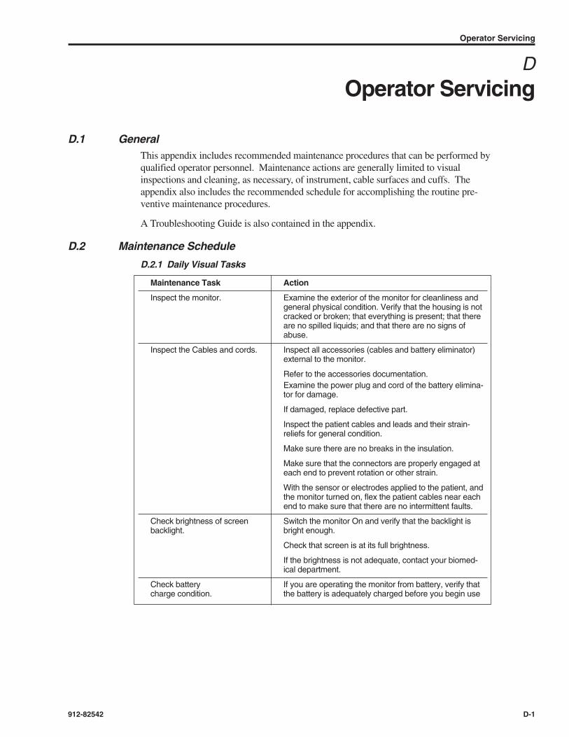
D.1 GeneralThis appendix includes recommended maintenance procedures that can be performed byqualified operator personnel. Maintenance actions are generally limited to visualinspections and cleaning, as necessary, of instrument, cable surfaces and cuffs. Theappendix also includes the recommended schedule for accomplishing the routine pre-ventive maintenance procedures.
A Troubleshooting Guide is also contained in the appendix.
D.2 Maintenance Schedule
D.2.1 Daily Visual Tasks
Operator Servicing
912-82542 D-1
DOperator Servicing
Maintenance Task Action
Inspect the monitor. Examine the exterior of the monitor for cleanliness andgeneral physical condition. Verify that the housing is notcracked or broken; that everything is present; that thereare no spilled liquids; and that there are no signs ofabuse.
Inspect the Cables and cords. Inspect all accessories (cables and battery eliminator)external to the monitor.
Refer to the accessories documentation.Examine the power plug and cord of the battery elimina-tor for damage.
If damaged, replace defective part.
Inspect the patient cables and leads and their strain-reliefs for general condition.
Make sure there are no breaks in the insulation.
Make sure that the connectors are properly engaged ateach end to prevent rotation or other strain.
With the sensor or electrodes applied to the patient, andthe monitor turned on, flex the patient cables near eachend to make sure that there are no intermittent faults.
Check brightness of screen Switch the monitor On and verify that the backlight is backlight. bright enough.
Check that screen is at its full brightness.
If the brightness is not adequate, contact your biomed-ical department.
Check battery If you are operating the monitor from battery, verify that charge condition. the battery is adequately charged before you begin use

D.2.2 Cleaning Tasks (As needed)
Caution
Do not immerse the monitor in liquid or use caustic or abrasive cleaners.
Caution
Do not spray or pour any liquid on the monitor or its accessories.
Caution
Do not allow any liquid to penetrate connectors or openings in the monitor’s chassis.
• To clean and disinfect the monitor, dampen a cloth with a commercial, nonabrasivecleaner, such as 70% isopropyl alcohol and wipe the top, bottom, and front surfaceslightly.
• For cables and cuffs, clean with a cleaning agent such as 70% isopropyl alcohol.
• If liquid is accidentally spilled on the monitor, clean and dry it thoroughly beforereuse.
Caution
After drying a wetted component (monitor, cable, sensor, battery eliminator, etc.)obtain the assistance of a qualified service person to assure safe operating condition.
D.2.3 Battery Maintenance
If the monitor has not been used for a long period of time, the battery will need charging.
• To charge the battery, connect the battery eliminator to an appropriate power supply.Connect the Battery Eliminator output to the monitor rear-panel connector.
Storing the monitor for a long period of time without charging the battery may degradethe battery’s capacity to store charge. A complete battery recharge requires 8 hours instandby mode or 14 hours in operational mode.
• We recommend that a qualified service person be requested to check the number ofdeep discharge cycles of the sealed lead-acid battery at 2-year intervals.
• Follow local governing ordinances and recycling plans regarding disposal or recyclingof batteries and other device components.
LIFEGARD ICG Operator’s Manual
D-2 912-82542

D.3 Troubleshooting Guide
D.3.1 Low Battery Indication
When the monitor fails to respond, check the battery symbol for battery charge status. Ifa low-charge on the battery icon is observed:
• Connect the battery eliminator input connector to the source power, and connect thebattery eliminator output to the monitor rear panel. Note that the monitor can be usedwhile the battery is being recharged.
• If, after a minimum of 4 recharging hours, the battery charge symbol does not indicateany retained charge, battery replacement may be required. Call a qualified service per-son for further troubleshooting. Refer to Appendix C for Technical Service andSupport instructions.
NOTE
Battery replacement requires access to the monitor’s internal assemblies and isnot intended for Operator-servicing.
Caution
The Real Time clock in the AN4700 is run from the battery. After recharging a run-down battery, check for correct date and time display. Reenter if necessary.
D.3.2 Error Messages
• If the monitor detects a malfunction that prevents you from using the monitor until themalfunction is corrected, you will see an Error message.
• An Error screen, containing an error code, indicates that the monitor is unable to per-form its monitoring functions because of the loss of software control or because of adetected hardware malfunction.
• If this is accompanied by a loss of monitoring alarm, press the front panel alarm buttonto silence the tone.
D.3.3 Operator Action
When an Error screen is displayed:
• Record the error code number.
• Before calling your local biomedical technician, verify that the battery is charged, andthat all power connections are correctly made.
• If the monitor continues to display the Error screen, call your local biomedical techni-cian and report the error code number. You will be advised of the remedial action to betaken by operator personnel.
NOTE
If Operator efforts to isolate the source of any apparent malfunction, or if access to the inside-case circuitry may be required, obtain technical assistance of quali-fied service personnel. Refer to Appendix E for instructions to obtain technicalsupport.
Operator Servicing
912-82542 D-3

E.1 GeneralAppendix E includes instructions for obtaining technical assistance and for returning theICG monitor for repairs.
E.2 Obtaining Technical AssistanceThe Life Care Systems Support Group is the resource for providing installation, preven-tative and corrective maintenance, technical and operator support, and parts, and docu-mentation provisioning for Analogic-supplied products.
To Contact the Life Care Systems Support Group:
Call: +1 978-977-3000 (MA and International)Spare Parts Ext. 4700Repairs Ext. 4700Fax: +1 978-977-6854email: [email protected]
E.3 Return Material ProcedureTo return a defective product to Analogic, you will need to obtain a Return MaterialAuthorization (RMA) number from our Life Care Systems Support Group. Please con-tact a Service Coordinator at:
Call: +1 978-977-3000 Ext. 4700Fax: +1 978-977-6854email: [email protected]
You will need to supply the Service Coordinator with the following information:
• The Model number(s) and Serial number(s) of the product,
• The quantity of items,
• The "Bill to" address for invoice purposes,
• The "Ship to" address,
• A Purchase Order number, and
• Details of the reported failure.
The Service Coordinator will then inform you of:
• The Return Material Authorization (RMA) number,
• The warranty or non-warranty status of the units being returned,
• Any repair charge.
Technical Services and Support
912-82542 E-1
ETechnical Services and Support

All returned material must be shipped “PREPAID” to the following address:
Analogic CorporationLife Care Systems8 Centennial DrivePeabody, MA 01960Attn: Receiving Dock BRMA#:______________
NOTE
Please reference your RMA number on both your purchase order and the shippinglabel.
LIFEGARD ICG Operator’s Manual
E-2 912-82542

Electromagnetic Compatibility
Reference: EN 60601-1-2:2001
Table G-2. Electromagnetic Immunity (ESD, EFT, Surge, Dips and Magnetic Field)
WARNING
Use of Accessories, transducers, and cables other than those specified may resultin increased emission and/or decreased immunity of the LIFEGARD ICG.
Guidance and Manufacturer’s Declaration
912-82542 F-1
FGuidance and Manufacturer’s Declaration
Guidance and Manufacturer’s Declaration — Electromagnetic Emissions
The LIFEGARD ICG is intended for use in the electromagnetic environment specified below. The customer orthe user of the LIFEGARD ICG should assure that it is used in such an environment.
Emissions Test Compliance Electromagnetic Environment Guidance
RF emissions Group 1 The LIFEGARD ICG uses RF energy only for its internal function.CISPR11 Therefore, its RF emissions are very low and are not likely to cause
any interference with nearby electronic equipment.
RF emissions Class B The LIFEGARD ICG is suitable for use in all establishment otherCISPR 11 than domestic and those directly connected to the public
low-voltage power supply network that supplies buildings used forHarmonic emissions Class A domestic purposes.IEC 61000-3-2
Voltage fluctuation/ CompliesFlicker emissionsIEC 61000-3-3

LIFEGARD ICG Operator’s Manual
F-2 912-82542
IEC 60601-1-2 Compliance Electromagnetic Environment —Immunity Test Test Level Level Guidance
Electrostatic ±2, ±4, ±6 kV contact ±2, 4, 6 kV Floors should be wood, concrete,discharge (ESD) ±2, ±4,±6 ±8 kV air ±2, 4, 6, 8 kV or ceramic tile. If floors are coveredIEC 61000-4-2 with synthetic material, the relative
humidity should be at least 30%.
Electrical fasttransient/burst IEC 61000-4-4 .• AC Power Mains
• Measurement I/O
Surge ±0.5, ±1 kV differential mode ±1 kVIEC 61000-4-5
±0.5, ±1, ±2 kV common mode ±2 kV
Voltage dips, <5% UT (>95% dip in UT) <5% UTshort interruptions for 0.5 cycle and voltage 40% UT (60% dip in UT) 40% UTvariations on for 5 cycles power supply AC 70% UT (30% dip in UT) 70% UTinput lines for 25 cycles IEC 61000-4-11 <5% UT (>95% dip in UT) <5% UT
for 5 cycles
Power frequency 3 A/m 3 A/m Power frequency magnetic fields should(50/60 Hz) be at levels characteristic of a typicalmagnetic field location in a typical commercialIEC 61000-4-8 or hospital environment.
NOTE: UT is the ac mains voltage prior to application of the test level.
±0.5, ±1 kV differential mode±2 kV common mode
N/A, Less than 3 meters
±0.5, 1 kV2 kV
N/A
Mains power quality should be that ofa typical commercial and/or hospitalenvironment.
Mains power quality should be that of atypical commercial and/or hospital envi-ronment. If the user of the LIFEGARDICG requires continued operation duringpower mains interruptions, it is recom-mended that the LIFEGARD ICG bepowered from an uninterruptible powersupply or a battery.
Guidance and Manufacturer’s Declaration — Electromagnetic Immunity
The LIFEGARD ICG is intended for use in the electromagnetic environment specified below. The customer orthe user of the LIFEGARD ICG should assure that it is used in such an environment.

Guidance and Manufacturer’s Declaration
912-82542 F-3
IEC 60601-1-2 Compliance Electromagnetic Environment —Immunity Test Test Level Level Guidance
RF Portable and mobile RF communicationsequipment should be used no closer toany part of the LIFEGARD ICG, includingcables, than the recommendedseparation distance calculated from theequation applicable to the frequency ofthe transmitter.
Recommended Separation Distance
Conducted 3 Vrms 1 Vrms IEC 61000-4-6 150 kHz to 80 MHz
Radiated RF 3 V/m 3 V/m IEC 61000-4-3 80 to 2500 MHz
Where P is the maximum output power ratingof the transmitter in watts (W) according to thetransmitter manufacturer and d is the recom-mended separation distance in meters (m).
Field strengths from fixed RF transmitters, asdetermined by an electromagnetic site survey,ashould be less than the compliance level ineach frequency range.b
Interference may occur in the vicinity of equip-ment with the following symbol:
a Field strengths from fixed transmitters, such as base stations for radio (cellular/cordless) telephones and landmobile radios, amateur radio, AM and FM radio broadcast, and TV broadcast cannot be predicted theoreticallywith accuracy. To assess the electromagnetic environment due to fixed RF transmitters, an electromagnetic sitesurvey should be considered. If the measured field strength in the location in which the LIFEGARD ICG is usedexceeds the applicable RF compliance level above, the LIFEGARD ICG should be observed to verify normaloperation. If abnormal performance is observed, additional measures may be necessary, such as re-orienting orrelocating the LIFEGARD ICG.
b Over the frequency range 150 kHz to 80 MHz, field strengths should be less than 1 V/m.
NOTE: These guidelines may not apply in all situations. Electromagnetic propagation is affected by absorptionand reflection from structures, objects and people.
d = [3.5] x P ; 150 to 80 MHz
d = [1.2] x P ; 80 to 800 MHz
d = [2.3] x P ; 800 to 2500 MHz
Guidance and Manufacturer’s Declaration — Electromagnetic Immunity
The LIFEGARD ICG is intended for use in the electromagnetic environment specified below. The customer orthe user of the LIFEGARD ICG should assure that it is used in such an environment.

LIFEGARD ICG Operator’s Manual
F-4 912-82542
Frequency of Transmitter 150 kHz to 80 MHz 80 to 800 MHz 800 to 2500 MHz
Equation
Rated Maximum Output Separation Distance Separation Distance Separation DistancePower of Transmitter
(watts) (meters) (meters) (meters)
0.01 0.35 0.12 0.23
0.1 1.11 0.37 0.74
1 3.50 1.17 2.33
10 11.1 3.70 7.40
100 35.0 11.7 23.3
For transmitters rated at a maximum output power not listed above, the separation distance d can be estimatedusing the equation in the corresponding column, where P is the maximum output power rating of the transmitter inwatts according to the transmitter manufacturer.
NOTE : These guidelines may not apply in all situations. Electromagnetic propagation is affected by absorption andreflection from structures, objects, and people.
Pd = [3.5 ] x Pd = [1.17 ] x Pd = [2.33 ] x
Guidance and Manufacturer’s Declaration — Electromagnetic Immunity
The LIFEGARD ICG is intended for use in the electromagnetic environment specified below. The customer orthe user of the LIFEGARD ICG should assure that it is used in such an environment.

Table G-1 lists accessories available for use with LIFEGARD ICG monitor. These maybe shipped as part of the initial order, or may be purchased from any distributor ofAnalogic Life Care Systems.
Table G-1. LIFEGARD ICG Accessories
Accessories
912-82542 G-1
GAccessories
Name Description Analogic Part Number Order Code
LIFEGARD ICG Provides mobile use of 21-00546 AN4700-AC080Roll Stand monitor
LIFEGARD ICG Domestic use (120V~) 10-62467-03 BAT-ELIM-AIncludes Line Cord
Battery Eliminator International use (230V~) 10-62467-04 BAT-ELIM-B
Includes line cord
NIBP Cuff–Latex Adult 21-00205-01 AN4K-AC012
Adult Plus 21-00205-02 AN4K-AC011
Small Adult 21-00205-03 AN4K-AC013
NIBP Hose Air Hose, 9 ft (3m) 21-00204-01 AN4K-AC015
NIBP Cuff–Non-Latex Adult 21-00205-04 AN4K-AC017
Adult Plus 21-00205-05 AN4K-AC016
Small Adult 21-00205-06 AN4K-AC018
NIBP Hose Non-Latex Air Hose, 9 ft (3m) 21-00204-02 AN4K-AC019
LIFEGARD ICG Connects Patient Dual 21-00122-01 AN4700-AC030Patient Cable Electrodes to monitor
LIFEGARD ICG Dual electrode to be 21-000317-01Dual Electrode attached to patient
Box of 10 sets of 4 21-000317-03 AN4700-AC031LIFEGARD ICG DualElectrodes
LIFEGARD ICG For integral thermal Printer Paper printer 28-600008
Box of 20 rolls of PrinterPaper AN4700-AC060
LIFEGARD ICG Creates an Impedance 21-00594-01 AN4700-AC001Simulator Cardiographic and ECG
waveform
LIFEGARD ICG Multi-Language Disk 912-82542V00R00 AN4700-AC101Operator’s Manual

Analogic CorporationLife Care Systems Division8 Centennial DrivePeabody, MA 01960-7987, USATel: 978-977-3000
Printed in the U.S.A.®Analogic Corporation
912-82542September, 2004