light and color - uni-freiburg.de
TRANSCRIPT
Matthias Teschner
Advanced Computer GraphicsLight and Color

University of Freiburg – Computer Science Department – 2
Rendering
What is visible in an image?
Transformations from model space to screen space
Ray-object intersections
Which color is it?
Shading / lighting
Rendering equation

University of Freiburg – Computer Science Department – 3
Outline
Context
Light
Color

University of Freiburg – Computer Science Department – 4
Light
How to quantify light/color? Flux, Irradiance, Radiance
How to quantify surface illumination? Irradiance
How to quantify pixel colors? Radiance
Light travelsalong rays
Light isemitted at
light sources
Incoming light /is absorbed and
scattered at surfaces
specular diffuse
Cameras capture light
University of Freiburg – Computer Science Department – 5
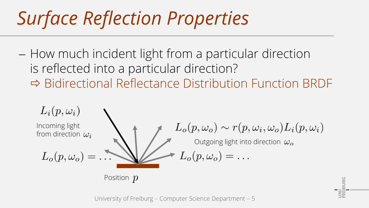
Surface Reflection Properties
How much incident light from a particular direction is reflected into a particular direction? Bidirectional Reflectance Distribution Function BRDF
Incoming lightfrom direction
Position
Outgoing light into direction

University of Freiburg – Computer Science Department – 6
Rendering Equation
How to compute reflected light into a particular direction given incident light from all possible directions? Rendering equation
Incoming lightfrom direction
Position
Rendering equationOutgoing light into direction , e.g., towards the camera, is a sum of weighted incident light

University of Freiburg – Computer Science Department – 7
The Importance of Light Modeling
Light
Color
Material
Rendering equation
Solving the rendering equation (Computing pixel colors)

University of Freiburg – Computer Science Department – 8
Outline
Context
Light
Color

University of Freiburg – Computer Science Department – 9
Light
Radiation modeled with photons
Photons
Light particles
Travel along a straight line at the speed of light
Characterized by a wavelength (perceived as color in the visible spectrum)
Photons travelalong rays

University of Freiburg – Computer Science Department – 10
Quantifying Light
Radiometric quantities characterize the propagation of electromagnetic radiation
Flux, irradiance, radiance
Radiation with wavelengths between 390 nm and 750 nm is visible to humans (blue light green light red light)
Radiometric quantities are represented by a spectrum
A distribution function of wavelength
Amount of light at each wavelength

University of Freiburg – Computer Science Department – 11
Flux
Radiant flux
Power
Radiant energy, i.e. number of photons, per time
Brightness, e.g., number of photons emitted by a source per time
Flux is actually radiant energy per time.
As photons carry varying energy depending on their wavelength, number of photons per time is an approximation that improvesthe intuition behind flux.

University of Freiburg – Computer Science Department – 12
Flux Density
Rate at which flux enters, leaves or passes an area
Describes strength of light with respect to a surface area (existing or virtual surface)
No directional information

University of Freiburg – Computer Science Department – 13
Flux Density - Variants
Irradiance - incident / incoming flux per surface
Radiosity - outgoing flux (reflected plus emitted)per surface
Radiosity – Outgoing flux per areaIrradiance – Incident flux per area

University of Freiburg – Computer Science Department – 14
Spatially Varying Flux Density
Irradiance at a position ?
Issues: position with zero area, no flux per position
Solution: infinitesimals, differentials, small quantities
Consider a small amount of flux incident to a small area around position
For , we have ,and the ratio converges to theirradiance at :
Irradiance at a position

University of Freiburg – Computer Science Department – 15
Overall Flux Incident to a Surface
Infinitesimally small amount of flux at a position
Flux over an area
Conceptually, dA converges to zero, butwe can still think of a small surface patch.
Area is discretized into surface patches.

University of Freiburg – Computer Science Department – 16
Towards Directional Quantities
How to quantify light from / into a direction?
E.g., light towards viewer or towards surfaces
Issue: Flux from / into a particular direction is zero
Analogous to flux per position
Solution: Flux from / into a range of directions
Represented by angles in 2D
Represented by solid angles in 3D

University of Freiburg – Computer Science Department – 17
Solid Angle
Area of a sphere surface divided by the squared sphere radius
E.g., solid angle of the entiresphere surface
Independent from the radius
E.g., solid angle of a hemisphere Wikipedia: Raumwinkel

University of Freiburg – Computer Science Department – 18
Solid Angle and Surface Area
E.g., from which directions does a point receive light from an area light source?
Solid angle of an arbitrary surface

University of Freiburg – Computer Science Department – 19
Infinitesimal Solid Angle and Surface Area
is an approximation
If an infinitesimally small area at position converges to zero, then the solid angle also converges to zero and the relationis correct in the limit

University of Freiburg – Computer Science Department – 20
Solid Angle Subtended by a Surface
How big does an object appear in an image? From which solid angle does a point receive light from a light source?

University of Freiburg – Computer Science Department – 21
Visibility Function
Position only contributes to , if it is visible from
Therefore,
with , if is visible from and , if is not visible from
University of Freiburg – Computer Science Department – 22
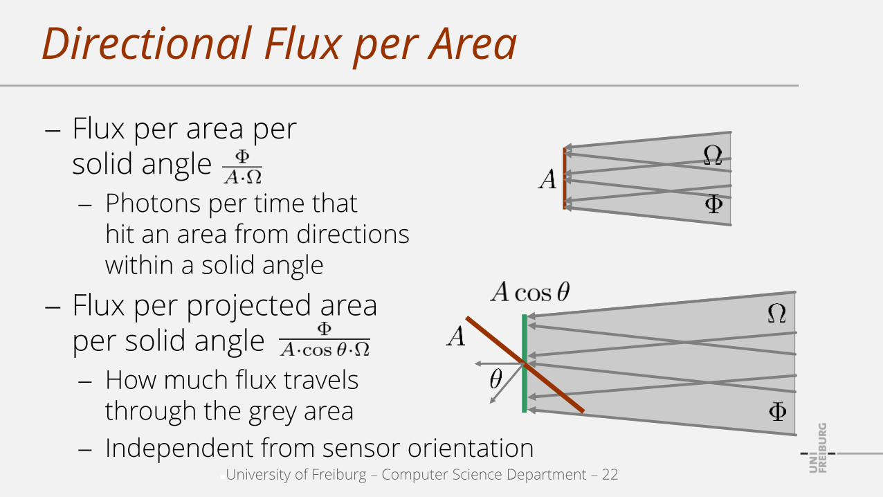
Directional Flux per Area
Flux per area per solid angle
Photons per time thathit an area from directionswithin a solid angle
Flux per projected area per solid angle
How much flux travels through the grey area
Independent from sensor orientation

University of Freiburg – Computer Science Department – 23
Radiance
If the area around a position converges to zero and the solid angle around direction converges to zero, then the flux that hits (passes, is reflected from) from (into) solid angle converges to zero and is the radiance at position
from (into) direction
The notation d2 indicates that two integrations(over area and over solid angle) are required to get a non-infinitesimal value .
L(x, ) characterizes the flux that travels through position x in direction .

University of Freiburg – Computer Science Department – 24
Radiance at a Position in a Direction
Actual setting
Flux that is transportedthrough an infinitesimallysmall cone
Simplified notion
Radiance at position in direction
Flux that is transported along a ray

University of Freiburg – Computer Science Department – 25
Flux Density and Radiance - Terms
Flux per area
Flux density
Incident / incoming flux density: Irradiance
Exitant / outgoing flux density: Radiosity
Flux per area (orthogonal to flux direction) per solid angle
Radiance
Incident, outgoing radiance: Radiance

University of Freiburg – Computer Science Department – 26
Radiance and Oriented Surfaces
Two areas around positions with
Angles between surface normal and flux direction :
Radiance at :
Radiance at :
Radiance describes the fluxwithin the grey area independentfrom the plane (sensor) orientation.

University of Freiburg – Computer Science Department – 27
Irradiance and Oriented Surfaces
Irradiance at :
Irradiance at :
Lambert’s Cosine Law
Irradiance on a surface is proportional to the cosine of the angle between surface normal and flux direction
i denotes an arbitrary orientation. Irradiance describes the effect of
the flux within the grey area ontoa surface. I.e., the orientation of the surface with respect to theflux direction matters.

University of Freiburg – Computer Science Department – 28
Lambert's Cosine Law
Angle between surface normal and light source direction influences the surface brightness
The same light source illuminatesa surface at different angles.The same flux and the same radianceis transported along the rays.
Surface receives more flux per area. Appears brighter.
Surface receives less flux per area. Appears darker.

University of Freiburg – Computer Science Department – 29
Discussion
Radiance characterize the flux that is transported between infinitesimally small surface areas
Irradiance characterizes the effect of this flux at these surface areas
Flux d is reflected / emitted from dA1 and incident to dA2. Distance from x1 to x2 is r. Angles between flux direction and surface normal are 1 and 2. Size of dA1 seen from x2 is the solid angle d2. d1 analogous.

University of Freiburg – Computer Science Department – 30
Discussion – Conservation of Radiance
Radiosity at :
Irradiance at :
Radiance at :
Radiance at :
Conservation of radiance. Radiance describes fluxtransported along a ray.

University of Freiburg – Computer Science Department – 31
Discussion – Inverse Square Law
Irradiance at an illuminated surface decreases quadratically with the distance from a light source
Surfaces appear darker with growing distance from light
Flux generated at A, arriving at A1 and A2:
Areas
IrradiancesAll planes are orthogonal to . Thus, cos = 1 for all planes.
University of Freiburg – Computer Science Department – 32
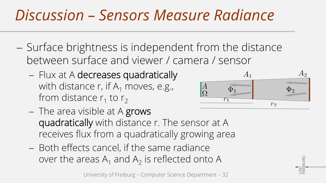
Discussion – Sensors Measure Radiance
Surface brightness is independent from the distance between surface and viewer / camera / sensor
Flux at A decreases quadraticallywith distance r, if A1 moves, e.g.,from distance r1 to r2
The area visible at A grows quadratically with distance r. The sensor at A receives flux from a quadratically growing area
Both effects cancel, if the same radiance over the areas A1 and A2 is reflected onto A
University of Freiburg – Computer Science Department – 33
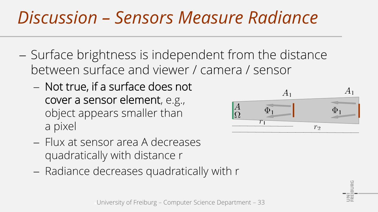
Discussion – Sensors Measure Radiance
Surface brightness is independent from the distance between surface and viewer / camera / sensor
Not true, if a surface does notcover a sensor element, e.g.,object appears smaller than a pixel
Flux at sensor area A decreasesquadratically with distance r
Radiance decreases quadratically with r

University of Freiburg – Computer Science Department – 34
Radiance and Sensors
Radiance
Is measured by sensors
Is computed in computer-generated images
Is preserved along lines in space
Does not change with distance
[Akenine-Möller et al.]
A sensor with a small areareceives light from a small set of directions, i.e. radiance
Idealized graphics model of an imaging sensor

University of Freiburg – Computer Science Department – 35
Discussion – Irradiance and Radiance
Illumination strength at a surface can be characterized by irradiance (flux per area)
Depends quadratically on the distance between surface and light source
Illumination strength at a sensor element can be cha-racterized by radiance (flux per area per solid angle)
Does not depend on the distance between surface and sensor

University of Freiburg – Computer Science Department – 36
Discussion – Irradiance and Radiance
Object surface receives less flux from light 2 than from light 1 (inverse square law). Both lights contribute to the illumination of the same surface element.
Camera captures the same radiance for both lights. d1 and d2 are of the same size into different directions. Light 1 and 2 contribute to different sensor elements.
Objectsurface
Camera
Light 1
Light 2
Brightness depends onirradiance.
Sensor responsedepends onRadiance.
Direction:Solid angle:

University of Freiburg – Computer Science Department – 37
Radiometric vs. Photometric Quantities
Radiometric quantities describe all types of radiation
Preferred in graphics research
E.g., flux, irradiance, radiosity, radiance
Photometric quantities describe visible radiation weighted with the sensitivity of the human eye
E.g., luminous flux [lumen], illuminance [lux], luminous exitance [lux], luminance [candela / m2]

University of Freiburg – Computer Science Department – 38
Summary
Flux describes the number of photons per time
More precisely photon energy per time
Irradiance and radiosity describe the flux into, through or from a surface per area
Irradiance describes the illumination of surfaces
Radiance describes the flow at a direction into or from a surface orthogonal to that direction per area per solid angle
Radiance is measured by sensors

University of Freiburg – Computer Science Department – 39
Outline
Context
Light
Color

University of Freiburg – Computer Science Department – 40
Introduction
Light consists of a set of photons
Photons are characterized by a wavelength within the visible spectrum from 390 nm to 750 nm
The distribution of wavelengths within this set is referred to as spectral power distribution (spectrum)
Spectra are perceived as colors

University of Freiburg – Computer Science Department – 41
Spectral Quantities
Flux, flux density and radiance depend on wavelength
Photons with a wavelength in a range i around i.

University of Freiburg – Computer Science Department – 42
Visible Spectrum
If the spectrum consists of a dominant wavelength,humans perceive a "rainbow" color (monochromatic)
If all wavelengths are equally distributed, humans perceive gray, ranging from black to white (achromatic)
Colors "mixed from rainbow colors" are chromatic
[Wikipedia: Visible spectrum]390 nm 750 nm
[Akenine-Möller et al.]
This spectrum corresponds to a ripe brown banana under white light (reflectance).
University of Freiburg – Computer Science Department – 43
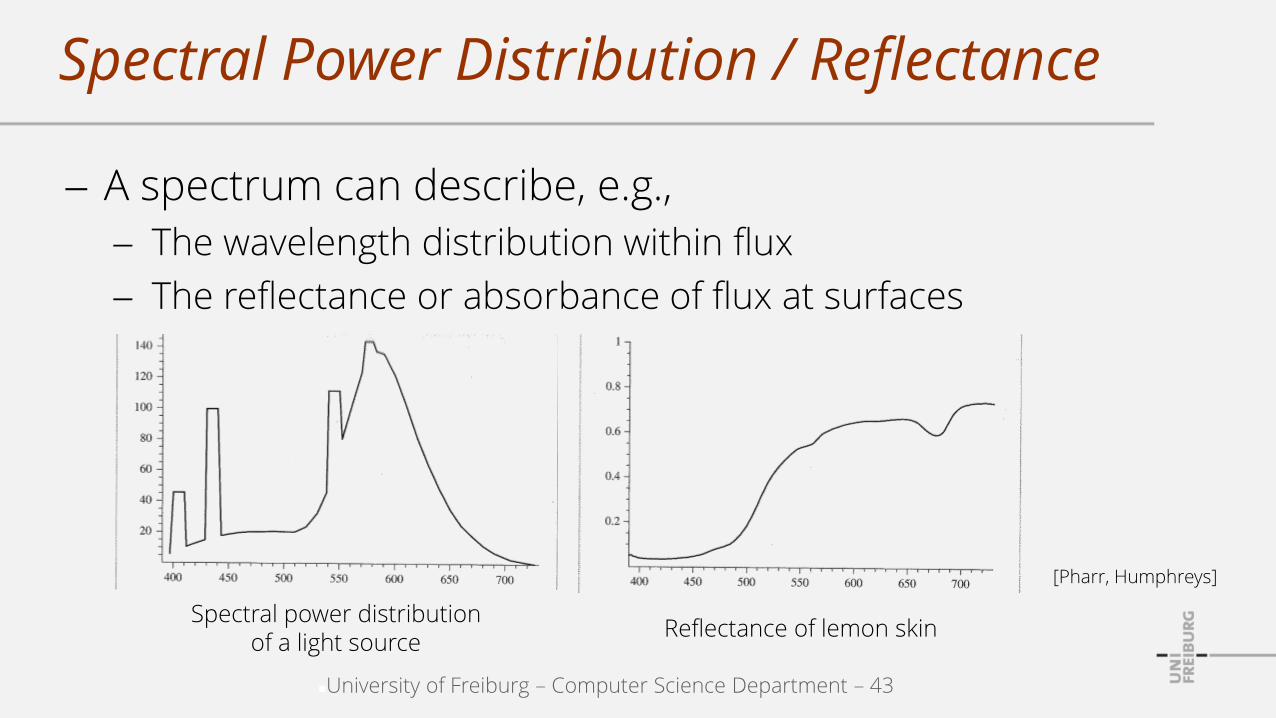
Spectral Power Distribution / Reflectance
A spectrum can describe, e.g.,
The wavelength distribution within flux
The reflectance or absorbance of flux at surfaces
[Pharr, Humphreys]
Spectral power distributionof a light source
Reflectance of lemon skin

University of Freiburg – Computer Science Department – 44
Representing a Spectrum
Spectrum
Uniform samples, e.g.
Non-uniform samples, e.g.,

University of Freiburg – Computer Science Department – 45
Flux vs. Spectral Flux
Color (spectrum) is typically represented with(RGB values, spectral flux values)
Raytracing concepts are described with (flux)
Can be flux
Can also be interpreted as a spectral flux vector
E.g., typically refers to
University of Freiburg – Computer Science Department – 46
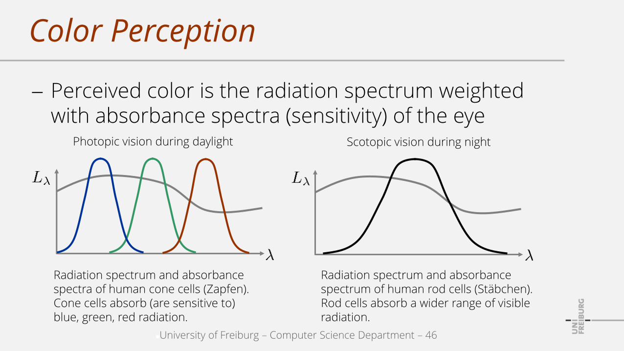
Color Perception
Perceived color is the radiation spectrum weighted with absorbance spectra (sensitivity) of the eye
Radiation spectrum and absorbancespectra of human cone cells (Zapfen). Cone cells absorb (are sensitive to) blue, green, red radiation.
Radiation spectrum and absorbancespectrum of human rod cells (Stäbchen). Rod cells absorb a wider range of visible radiation.
Photopic vision during daylight Scotopic vision during night

University of Freiburg – Computer Science Department – 47
Color Perception
Basis functions map from infinite-dimensional space to low-dimensional space (3D in daylight, 1D at night)
In daylight, three cone signals (X,Y,Z) are interpreted by the brain as color
Photopic vision during daylight Scotopic vision during night
x(), y(), z() are the absorbance spectra of human cone cells.
i() is the absorbance spectrum of a rod cell.

University of Freiburg – Computer Science Department – 48
Color Perception
Is a complex phenomenon
Wikipedia: Color constancy
A and B are of the samecolor / brightness.
Perception (partially) adaptsto changing illumination.
A and B are of the same color.
A
B

University of Freiburg – Computer Science Department – 49
CIE XYZ Color Space
Proposed by the International Commission on Illumination CIE in 1931
Motivated by trichromacy model Three cone types Three signals / numbers for a color
Spectrum of L is converted to X, Y, Z with color-matching functions x(), y(), z().
Color-matching functions x(), y(), z() have been experimentally estimated to map all perceivable colors to (X, Y, Z) values in the range from 0 to 1

University of Freiburg – Computer Science Department – 50
CIE xy Chromaticity Diagram
XYZ represents color and brightness / luminance
Two values are sufficient to represent color
Monochromatic colors areon the boundary
The center is achromatic [Wikipedia: CIE 1931 color space]

University of Freiburg – Computer Science Department – 51
CIE RGB Color Space
RGB color space
Spectrum of L is converted to R, G, B given the color-matching functions
The color-matching functions consider the spectra of real display primaries (e.g. LED, LCD, plasma cells)
[Wikipedia: CIE 1931 color space]

University of Freiburg – Computer Science Department – 52
Different sets of primary colors result in different sets of color-matching functions
CIE RGB Color Space
[Pharr, Humphreys]
Spectra of red, green, blue for an LCD display
Spectra of red, green, blue for an LED display

University of Freiburg – Computer Science Department – 53
Conversion XYZ / RGB
Depends on the particular set of spectra of the primary display colors
E.g., sRGB for HDTV
Negative matrix coefficientsindicate that XYZ values couldresult in negative RGB values,i.e. not all perceivable colorscan be represented / generatedwith RGB.

University of Freiburg – Computer Science Department – 54
Display Devices
xy chromaticity diagram
Three display / primary colors
Diagram indicates an example
Can only reproduce colorswithin the spanned triangle(gamut)
Colors outside the gamut are not properly displayed on the respective monitor
[Akenine-Mölleret al.]

University of Freiburg – Computer Science Department – 55
RGB Color Space
Three primaries: red, green, blue
Magenta (1,0,1)
Blue (0,0,1) Cyan (0,1,1)
White (1,1,1)
Black (0,0,0)
Green (0,1,0)
Yellow (1,1,0)Red (1,0,0)
University of Freiburg – Computer Science Department – 56
RGB Color Space - Lights
Light source color
E.g., yellow light (1, 1, 0)
Emits a spectrum with maximum red and green components
The spectrum does not contain any blue
The RGB values describe the amount of the respective color component in the emitted light

University of Freiburg – Computer Science Department – 57
RGB Color Space - Surfaces
Surface color / reflectance
E.g., yellow object (1, 1, 0)
Perfectly reflects red and green components of the incoming light
Perfectly absorbs the blue component of the incoming light
The RGB values describe how much of the respective incoming color component is reflected ("one minus value" describes how much is absorbed)

University of Freiburg – Computer Science Department – 58
Summary
Distribution of wavelengths within the perceived radiance is referred to as spectral power distribution or spectrum
Spectra are weighted with absorption spectra of the eye and perceived as colors
Three cone types for daylight vision motivate XYZ space. XYZ space can represent all perceivable colors RGB space represents displayable colors Colors of display devices are restricted to a gamut
that does not contain all perceivable colors Ray tracers can work with arbitrary representations Conversion to RGB for display purposes