light tower - wacker neusonproducts.wackerneuson.com/manuals/operators/0155773en_002.pdf · light...
TRANSCRIPT

www.wackergroup.com
Light Tower
LTC 4L
OPERATOR’S MANUAL
0155773en 002
0603
0 1 5 5 7 7 3 E N

BELGIE1730 ASSE-MOLLEM ASSESTEENWEG 17 Tel. (32) 02-4528509+074040 Herstal 4 Avenue9800 Deinze Kortrijkse Steenweg 400 Tel. (09)-386 8529B - 6041 Gosselies Rue Adrienne Bolland s/n Tel. 071-372450
ÇESKÁ REPUBLIKA19402 PRAHA 9-HLOUBETIN KOLBENOVA 259 Tel. (0042) 2 862165
DANMARK2690 KARLSLUNDE RØRGANGEN 6 Tel. 46 15 36 008200 Arhus N Randersvej 346 Tel. 86-2317775250 Odense SV Holkebjergvej 56A Tel. 66-172170
ESPAÑA28850 TORREJON DE ARDOZ (MADRID) POLIGONO INDUSTRIAL LAS MONJAS Tel. (34) 91-6757525 / 85
CALLE PRIMAVERA 1108780 PALLEJA (Barcelona) PRAT DE LA RIBA, 184 Tel. (93)-663227341700 Dos Hermanas (Sevilla) Poligono Industrial La Palmera Tel. (95)-4691129
Nave 14 Tel. (95)-469112946133 Meliana (Valencia) Calle Salvador Giner, 6 Tel. (96)-149210215890 Santiago de Compostela (La Coruña) Poligono Industrial el Tambre, Via Pasteur, 47a Tel. (981) 573366 / 67
SUOMIFIN 04250 KERAVA Peltomäenkatu 7 Tel. (358) 9-274 4740
FRANCE77170 BRIE COMTE ROBERT 335, RUE GLORIETTE—ZAC DU TUBOEUF Tel. (33) 1-60623000Aix en Provence 13540 Puyricard Tel. 4 42630526Arras 62217 Beaurains Tel. 3 21235361Bordeaux 33700 Merignac Tel. 5 56343346Bourges 18390 St. Germain du Puy Tel. 2 48652015Lyon 69740 Genas Tel. 4 78401384Nancy 54180 Heillecourt Tel. 3 83565801Rennes 35510 Cesson Sevigne Tel. 2 99321522Toulouse 31270 Cugnaux Tel. 5 61075250Kehl 77694 Kehl-Goldscheuer Tel. (0590) 9321
HUNGARIA1106 BUDAPEST Kada u. 137 Tel. (36) 1-260 8668
IRELANDDUBLIN 13 127A. BALDOYLE INDUSTRIAL ESTATE Tel. (00353) 01-8320218
ITALIA40016 SAN GIORGIO DI PIANO (Bologna) Via Due Agosto, 1980, Strage di Bologna, 3 Tel. 39.05.665.566 - 665.157400125 ACILIA (Roma) Viale Enrico Ortolani, 262 Tel. 39 . 06 . 521924620041 Agrate Brianza (Mi) Via Archimede, 31 Tel. 39. 039.699 0136
NEDERLAND3821 BJ AMERSFOORT COBOLWEG 1 Tel. 033 - 450 40 452984 BL Ridderker Glasblazerstraat 7 Tel. 0180 - 41 70 567418 EZ Deventer Arnbergstraat 9 Tel. 0570 - 63 00 875684 PS Best De Dintel 37 Tel. 0499 - 33 04 331704 RT Heerhugowaard Einsteinstraat 4d Tel. 072 - 574 20 789411 XN Beilen De Hanekampen 19 Tel. 0593 - 52 31 24
NORGE1481 HAGAN TYRIVN. 7 Tel. (47) 6705-1310
POLSKA05�850 OŻARÓW MAZOWIECKI UL. KONOTOPSKA 4 Tel. (48) 22 722 20 5962�081 Wysogotowo k. Poznania ul. Kamienna 1 Tel. (061) 814�3797
PORTUGAL2785-S. Domingos De Rana Urbanização Industrial de Trajouce, Lote 1 Tel. (351) 21 4443561 / 874785-S. Romao do Coronado Lg. do Soeiro, Apartado 2 Tel. (351) 22 982 7992 / 93
SVERIGE24734 SÖDRA SANDBY SKATTEBERGAVÄGEN 13 Tel. (46) 046-5787016170 Bromma Karlsbodavägen 17E Tel. 08-28286041749 Göteborg Knipplekullen 3A Tel. 031-551362
SCHWEIZ8305 Dietlikon Bahnhofstrasse 3 Tel. (41) 1-8353939
TURKIYE81120 K. Bakkalköy-ISTANBUL Karaman Çiftligi Cad. No: 55 Tel. (90) 216 573 062135350 Üçkuyular-Izmir Mithatpasa Cad. No. 1189 Tel. (90) 232 259 8944Ostim 06370 Ankara Alinteri Bulvari No. 210 Tel. (90) 312 385 6438/6439

Light Tower Table of Contents
1. Foreword 3
2. Safety Information 4
2.1 Laws Pertaining to Spark Arresters ...................................................... 4
2.2 Operating Safety .................................................................................. 5
2.3 Operator Safety while using Internal Combustion Engines .................. 6
2.4 Towing Safety ....................................................................................... 7
2.5 Service Safety ...................................................................................... 8
2.6 Label Locations .................................................................................... 9
2.7 Safety and Operating Labels .............................................................. 11
3. Technical Data 18
3.1 Trailer ................................................................................................. 18
3.2 Generator ........................................................................................... 19
3.3 Engine ................................................................................................ 20
4. Operation 21
4.1 Locating Trailer ................................................................................... 21
4.2 Leveling Trailer ................................................................................... 22
4.3 Adjusting Lights .................................................................................. 22
4.4 Preparing Trailer for Towing or Lifting ................................................ 23
4.5 Raising Tower (Manual Winch System) ............................................. 23
4.6 Lowering Tower .................................................................................. 25
4.7 Control Panels .................................................................................... 27
4.8 Starting ............................................................................................... 28
4.9 Automatic Shutdown .......................................................................... 28
4.10 Operation ............................................................................................ 29
4.11 Stopping ............................................................................................. 29
4.12 Derating .............................................................................................. 29
4.13 Receptacles ........................................................................................ 30
wc_bo0155773002enTOC.fm 1

Table of Contents Light Tower
5. Maintenance 32
5.1 Installing / Removing Light Fixtures ....................................................325.2 Replacing / Removing Bulbs ...............................................................335.3 Daily Inspection ...................................................................................335.4 Air Cleaner ..........................................................................................345.5 Engine Oil ............................................................................................355.6 Engine Maintenance ............................................................................365.7 Troubleshooting ...................................................................................375.8 Schematic for 60 Hz Metal Halide 4-Light Units ..................................385.9 Schematic for 60 Hz High Pressure Sodium 4-Light Units ..................405.10 Generator Capacitor Excitation Schematic 60 Hz. ..............................425.11 Trailer Wiring .......................................................................................435.12 Engine Wiring - Lombardini .................................................................445.13 Control Panel Wiring ...........................................................................45
wc_bo0155773002enTOC.fm 2

CALIFORNIA
Proposition 65 Warning:
Diesel engine exhaust, some of its constituents, and certain vehiclecomponents contain or emit chemicals known to the State of Californiato cause cancer and birth defects or other reproductive harm.
1. Foreword
This manual provides information and procedures to safely operateand maintain this Wacker model. For your own safety and protectionfrom injury, carefully read, understand and observe the safetyinstructions described in this manual.
Keep this manual or a copy of it with the machine. If you lose thismanual or need an additional copy, please contact WackerCorporation. This machine is built with user safety in mind; however,it can present hazards if improperly operated and serviced. Followoperating instructions carefully! If you have questions about operatingor servicing this equipment, please contact Wacker Corporation.
The information contained in this manual was based on machines inproduction at the time of publication. Wacker Corporation reserves theright to change any portion of this information without notice.
All rights, especially copying and distribution rights, are reserved.
Copyright 2003 by Wacker Corporation.
No part of this publication may be reproduced in any form or by anymeans, electronic or mechanical, including photocopying, withoutexpress written permission from Wacker Corporation.
Any type of reproduction or distribution not authorized by WackerCorporation represents an infringement of valid copyrights and will beprosecuted. We expressly reserve the right to make technicalmodifications, even without due notice, which aim at improving ourmachines or their safety standards.
WARNING
wc_si000045gb.fm 3

Safety Information Light Tower
2. Safety Information
This manual contains DANGER, WARNING, CAUTION, and NOTEcallouts which must be followed to reduce the possibility of personalinjury, damage to the equipment, or improper service.
This is the safety alert symbol. It is used to alert you to potentialpersonal injury hazards. Obey all safety messages that follow thissymbol to avoid possible injury or death.
DANGER indicates an imminently hazardous situation which, if notavoided, will result in death or serious injury.
WARNING indicates a potentially hazardous situation which, if notavoided, could result in death or serious injury.
CAUTION indicates a potentially hazardous situation which, if notavoided, may result in minor or moderate injury.
CAUTION: Used without the safety alert symbol, CAUTION indicatesa potentially hazardous situation which, if not avoided, may result inproperty damage.
Note: Contains additional information important to a procedure.
2.1 Laws Pertaining to Spark Arresters
Notice: State Health Safety Codes and Public Resources Codesspecify that in certain locations spark arresters be used on internalcombustion engines that use hydrocarbon fuels. A spark arrester is adevice designed to prevent accidental discharge of sparks or flamesfrom the engine exhaust. Spark arresters are qualified and rated bythe United States Forest Service for this purpose.
In order to comply with local laws regarding spark arresters, consultthe engine distributor or the local Health and Safety Administrator.
DANGER
WARNING
CAUTION
wc_si000045gb.fm 4

Light Tower Safety Information
2.2 Operating Safety
Familiarity and proper training are required for the safe operation ofequipment! Equipment operated improperly or by untrained personnelcan be dangerous! Read the operating instructions contained in boththis manual and the engine manual and familiarize yourself with thelocation and proper use of all controls. Inexperienced operators shouldreceive instruction from someone familiar with the equipment beforebeing allowed to operate the machine.
2.2.1 The area immediately surrounding the light tower should be clean,neat, and free of debris.
2.2.2 ALWAYS be sure machine is on a firm, level surface and will not tip,roll, slide, or fall while operating.
2.2.3 NEVER start a unit in need of repair.
2.2.4 Lower tower when not in use, or if high winds or electrical storms areexpected in the area.
2.2.5 ALWAYS make certain machine is well-grounded and securelyfastened to a good earthen ground per national and local regulations.
2.2.6 The tower extends up to 9 m (30 ft.). Make sure area above trailer isopen and clear of overhead wires and obstructions.
2.2.7 Bulbs become extremely hot in use! Allow bulb and fixture to cool 10–15 minutes before handling.
2.2.8 Keep area behind trailer clear of people while raising and loweringmast! Never raise, lower or turn mast while unit is operating!
2.2.9 Trailer must be leveled and outriggers extended before raising tower.Outriggers must remain extended while tower is up.
2.2.10 If for any reason any part of mast hangs up or winch cable developsslack while raising or lowering tower, STOP immediately! Contact anauthorized WACKER service representative.
2.2.11 NEVER remove mast locking pin while tower is up!
2.2.12 NEVER use tower if insulation on electrical cord is cut or worn through.
2.2.13 NEVER operate lights without protective lens cover in place or with alens cover that is cracked or damaged!
2.2.14 NEVER adjust mast while unit is operating.
2.2.15 NEVER raise the mast or operate the light tower in high winds.
WARNING
wc_si000045gb.fm 5

Safety Information Light Tower
2.3 Operator Safety while using Internal Combustion Engines
Internal combustion engines present special hazards during operationand fueling! Read and follow warning instructions in engine owner'smanual and safety guidelines below. Failure to follow warnings andsafety guidelines could result in severe injury or death.
2.3.1 NEVER operate machine indoors unless exhaust fumes can beadequately ventilated.
2.3.2 DO NOT fill or drain fuel tank near an open flame, while smoking, orwhile engine is running.
2.3.3 ALWAYS refill fuel tank in well-ventilated area.
2.3.4 DO NOT touch or lean against hot exhaust pipes.
2.3.5 ALWAYS replace fuel tank cap after refueling.
2.3.6 DO NOT remove engine coolant cap when engine is hot. Contents arehot and under pressure.
2.3.7 DO NOT use gasoline or other types of fuels or flammable solvents toclean parts, especially in enclosed areas. Fumes from fuels andsolvents can become explosive.
2.3.8 ALWAYS keep area around muffler free of debris such as leaves,paper, cartons, etc. A hot muffler could ignite them, starting a fire.
DANGER
wc_si000045gb.fm 6

Light Tower Safety Information
2.4 Towing Safety
Towing a large trailer requires special care! Both the trailer and vehiclemust be in good condition and securely fastened to each other toreduce the possibility of an accident.
2.4.1 ALWAYS check that the hitch and coupling on the vehicle are ratedequal to, or greater than, the trailer's “gross vehicle weight rating”(GVWR).
2.4.2 ALWAYS inspect the hitch and coupling for wear or damage. DO NOTtow trailer using defective parts!
2.4.3 ALWAYS make sure the coupling is securely fastened to the vehicle.
2.4.4 ALWAYS check tires on trailer for tread wear, inflation, and condition.Replace worn tires.
2.4.5 ALWAYS connect the safety chains.
2.4.6 ALWAYS make sure directional and trailer lights are connected andworking properly.
2.4.7 ALWAYS check that lug nuts holding wheels are tight and that noneare missing.
2.4.8 Maximum recommended speed for highway towing is 72 km/hour (45MPH). Recommended off-road towing speed is not to exceed 16 km/hour (10 MPH) or less depending on terrain.
2.4.9 ALWAYS refer to the applicable Department of Transportationregulations before towing.
WARNING
wc_si000045gb.fm 7

Safety Information Light Tower
2.5 Service Safety
HIGH VOLTAGE! This unit uses high voltage circuits capable ofcausing serious injury or death. Only a qualified electrician shouldtroubleshoot or repair electrical problems occurring in this equipment.
2.5.1 ALWAYS replace safety devices and guards after repairs andmaintenance.
2.5.2 Before servicing light tower, make sure engine start switch is turned toOFF, circuit breakers are open (off), and negative terminal on batteryis disconnected. NEVER perform even routine service (oil/filterchanges, cleaning, etc.) unless all electrical components are shutdown.
2.5.3 DO NOT allow water to accumulate around the base of the machine.If water is present, move the machine and allow it to dry beforeservicing.
2.5.4 DO NOT service machine if clothing or skin is wet.
2.5.5 ALWAYS keep hands, feet, and loose clothing away from moving partson generator and engine.
2.5.6 ALWAYS keep machine clean and labels legible. Replace all missingand hard-to-read labels. Labels provide important operatinginstructions and warn of dangers and hazards.
2.5.7 ALWAYS make sure slings, chains, hooks, ramps, jacks and othertypes of lifting devices are attached securely and have enough weight-bearing capacity to lift or hold the machine safely. Always remainaware of the position of other people around you when lifting themachine.
WARNING
wc_si000045gb.fm 8

Light Tower Safety Information
2.6 Label Locations
wc_si000045gb.fm 9

Safety Information Light Tower
wc_si000045gb.fm 10

Light Tower Safety Information
2.7 Safety and Operating Labels
Wacker machines use international pictorial labels where needed.These labels are described below:
Ref. Label Meaning
A DANGER! A non-secured, falling mast will cause serious injury or death if a person is hit. To secure mast, verify automatic locking pin has engaged to secure tower upright.
B WARNING! Avoid crushing area.
C WARNING! Completely lower tower before tilting mast. Tilting an extended mast could cause serious injury or death.
D Telescoping Tower:Pull and hold tower automatic locking pin before cranking tower up. Relese pin after one turn of winch handle.
Collapsing Tower:Ensure that the automatic locking pin engages all sections of tower before travel.
wc_si000045gb.fm 11

Safety Information Light Tower
E DANGER! Contact with overhead electrical power lines will cause serious injury or death. Do not position light tower under electri-cal power lines.
F CAUTION! Lifting point
G WARNING! Secure mast in transport lock before lift-ing or towing. A loose swinging mast could cause personal injury or machine damage.
H DANGER! Asphyxiation hazard. Read the opera-tor’s manual for instructions. No sparks, flames, or burning objects near machine. Stop the engine before adding fuel. Use only diesel fuel.
Ref. Label Meaning
wc_si000045gb.fm 12

Light Tower Safety Information
I DANGER! Asphyxiation hazard. Read the opera-tor’s manual for instructions. No sparks, flames, or burning objects near machine. Stop the engine before adding fuel. Use only diesel fuel.
DANGER! Contact with overhead electrical power lines will cause serious injury or death. Do not position light tower under electri-cal power lines.
WARNING! Completely lower tower before tilting mast. Tilting an extended mast could cause serious injury or death.
J DANGER! Electrical storage device within. Contact a qualified electrician for service or to open electrical box. Electric shock will cause serious injury or death.
K Electrical ground.
L WARNING! Stand clear of front and rear of machine when mast is being tilted up or down.
M WARNING! Hot surface.
Ref. Label Meaning
wc_si000045gb.fm 13

Safety Information Light Tower
N A nameplate listing the Model Number, Item Number, Revision, and Serial Num-ber is attached to each unit. Please record the information found on this plate so it will be available should the name-plate become lost or damaged. When ordering parts or requesting service infor-mation, you will always be asked to spec-ify the model, item number, revision number, and serial number of the unit.
O WARNING! Ultraviolet radiation from lamp can cause serious skin and eye irritation. Use only with provided undamaged lens cover and fixture.
Ref. Label Meaning
wc_si000045gb.fm 14

Light Tower Safety Information
Ref. Label
P
wc_si000045gb.fm 15

Safety Information Light Tower
Q
R
S
Ref. Label
� � � � � � � � � � � � � � � � � � � � � �� � � � � � � � � � � � � � � � � � � � � � � � � � � � � � � � � � � � � � � � � � � � � � � � � � � � � � � � � � � � �
� � � � � � � � � � � � � � � � � � � � � �
� � � � � � � � � � � � � � � � � � � � � � � � � �
� � � � � � � � � � � � � � � � � � � � � � � � � � �
� � � � � � � � � � � � � � � � � � � � � � � � � � � �
� � � � � � � �
� � � � � � � � � � � � � � � � � � � � � � � � � � � � � �
� � � � � � � �
� � � � � � � � � � � � � � � � � � � �
� � � � � � � � � � � � � � � � � � � � � � � � � �
� � � � � � � � � � � � � � � � � � � � � � � � � � � � !
� � � � � � � � � � � � � � � � � � � � � � � � � � � � � � � �
� � � � � � � � � � �
� � � � � � � � � � � � � � � � � � " � � � � � � " � � �
� � � � � � � � � � �
� � � � � � � � � � � � � � � � � � � � � � � " � � � � � � � � � � � � � � �
� � � � � � � � � � � � � � � � � � � � � � � �
� � � � � � � � � � � � � � � � � � � � � � � �
� � � � � � � � � � � � � � � � � � � � � � � � � � � � � �
� � � � � � � � � � � � � � � � � � � � � � � � � � � � � � � �
� � � � � � � � � � � � � � � � � � � �
� � � � � � � � � � � � � � � � � � � � � � � � � � � � � � � �
� � � � � � � � � � � � � � � � � � � � � � � � � � � �
� � � � # � � � � � � " � � � � � � � � � � � � � � � � � �
� � � � � � � � � � � � � � � � � � � � � � � � � � �
� � � � � � � � � � � � � � � � � � � � � �
� � � � � � � � � � � � � � � � � � � � � � � � � � � � � � � � � � � � � �
� � � � � � � � � � � � � � � � � � � � � � � � � � � � � �
� � � � � � � � �
� � � � � � � � � � � � � � � � � � � � � � � � � � � � � � � � � � � � � �
� � � � � � � � �
� � � � � � � � � � � � � � � � � � � � � � � � � � � � � � � � � � � � � � �
� � � � � � � � � � � � � � � � �
� � � � � � � � � � � � � � � � � � � � � � � � � � � � � ���$%�
wc_si000045gb.fm 16

Light Tower Safety Information
Ref. Label Meaning
This machine may be covered by one or more patents.
Certification Label (VIN Number)Also attached to each unit is a Certifica-tion Label. This label specifies that the trailer conforms with all Federal Motor vehicle standards in effect at the time of manufacture. It includes the Vehicle Identification Number (VIN) for the trailer.
wc_si000045gb.fm 17

Technical Data Light Tower
3. Technical Data
3.1 Trailer
LTC 4L0009311
Trailer
Operating weight (GVWR)
kg (lbs.)875 (1929)
Travel Dimensions (l x w x h)
cm (in.) 390 x 125 x 160(153 x 48 x 63)
Trailer length cm (in.) 335 (132)
Height - mast extended m (ft.) 9 (30)
Lighting system (1000 W) 4
Ballast Coil and core
Max. lighting coverage @ 0.5 ft. candles
acres (m2) Metal Halide - 7 (30,400)High Pressure Sodium - 9 (39,000)
Tires size ST175 / 80D13
wc_td000045gb.fm 18

Light Tower Technical Data
3.2 Generator
LTC 4L0009311
Generator
Frequency Hz 60 ± 2
Continuous output kW 6.0
Output volts/phase 120 / 240, 1Ø
Amps A 50 / 25
Excitation type Capacitor / Brushless
Power factor 1.0
Voltage regulation - No load to full load
%± 5.0
Speed (no-load) rpm 1800
wc_td000045gb.fm 19

Technical Data Light Tower
3.3 Engine
LTC 4L0009311
Engine
Make Lombardini
Model LDW903
Type 3-cylinder, 4-cycle, liquid cooled diesel
Maximum power rating kW (Hp) 9.0 (12.1)
Operating power rating kW (Hp) 8.1 (10.9)
Operating speed (no-load)
rpm1800
Alternator V / A / W 12 / 45 / 540
Battery V/Ah/CCA 12 / 450
Air cleaner type dry-type element
Fuel type No. 2 diesel
Fuel tank capacity l (gal.) 114 (30)
Fuel consumption l (gal.) / hr. 1.67 (0.44)
Running time hours 68
Coolant capacity l (qts.) 4.7 (5.0)
Oil capacity l (qts.) 2.4 (2.5)
Oil weight SAE 15W40 CD or higher
wc_td000045gb.fm 20

Light Tower Operation
4. Operation
4.1 Locating Trailer
See Graphic: wc_gr000531
4.1.1 For maximum light coverage locate tower at ground level or in a spothigher than the area being lighted.
4.1.2 Position trailer on a firm, flat surface clear of overhead wires andobstructions. Be sure that there is enough area for outriggerextensions to be fully extended.
4.1.3 Connect ground stud (l) located on trailer frame to a good earthenground.
The tower extends up to 9 m (30 ft.). Make sure area above trailer isopen and clear of overhead wires and obstructions.
WARNING
wc_tx000133gb.fm 21

Operation Light Tower
4.2 Leveling Trailer
See Graphic: wc_gr000531, wc_gr000534
Trailer must be leveled and outriggers extended before raising tower.Outriggers must remain extended while tower is up. Failure to leveltrailer or extend outriggers will severely reduce the stability of the unitand could allow tower to tip and fall.
4.2.1 Pull locking pin on tongue jack (a) and rotate jack 90° as shown inillustration above. Make sure jack snaps into position.
Block or chock trailer wheels (b). Crank jack down to raise trailertongue off vehicle.
4.2.2 Pull outrigger lock pin (c) to release outrigger. Pull both outriggerextensions (d) out until you feel pin lock back in place. Rotate jacks (e)down until they snap into position.
4.2.3 Rotate rear jack (f) down, as shown, making sure it snaps into place.
4.2.4 Extend jack(s) on the highest side(s) of the trailer until they rest firmlyon the ground. Extend remaining jacks until trailer is level.
4.3 Adjusting Lights
See Graphic: wc_gr000534
Each light fixture can be aimed up, down, left or right. Position eachfixture by loosening toolless light adjusters (g) and aiming light up ordown. Loosen nut (h) to turn light fixtures left or right. Tightenadjusters and nuts after positioning lights.
Always return light fixtures to aim at ground when mast is in the cradlefor towing.
WARNING
wc_tx000133gb.fm 22
Light Tower Operation
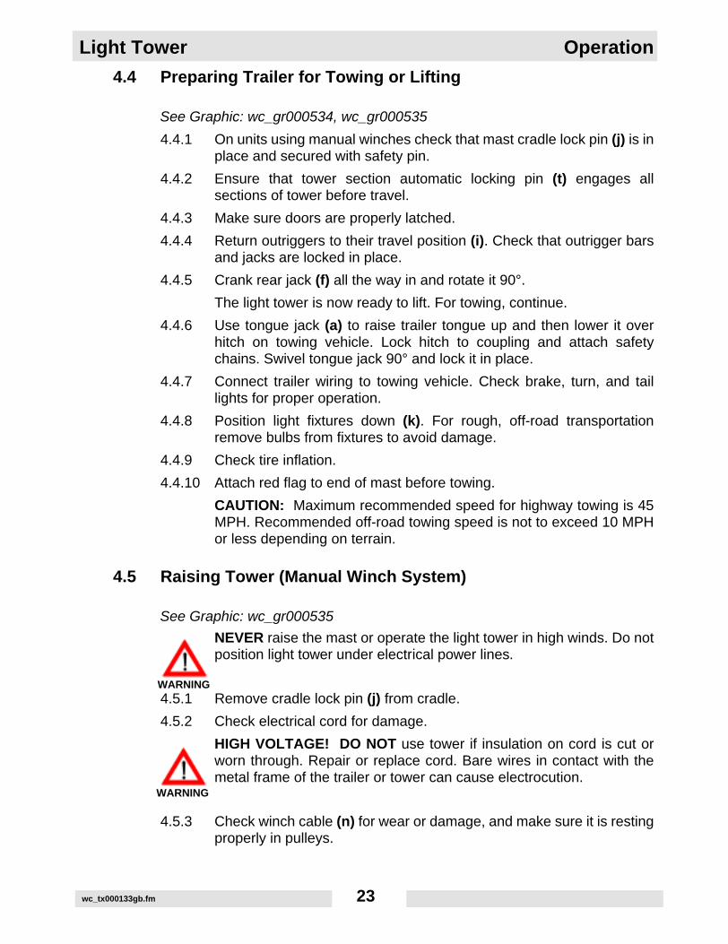
4.4 Preparing Trailer for Towing or Lifting
See Graphic: wc_gr000534, wc_gr000535
4.4.1 On units using manual winches check that mast cradle lock pin (j) is inplace and secured with safety pin.
4.4.2 Ensure that tower section automatic locking pin (t) engages allsections of tower before travel.
4.4.3 Make sure doors are properly latched.
4.4.4 Return outriggers to their travel position (i). Check that outrigger barsand jacks are locked in place.
4.4.5 Crank rear jack (f) all the way in and rotate it 90°.
The light tower is now ready to lift. For towing, continue.
4.4.6 Use tongue jack (a) to raise trailer tongue up and then lower it overhitch on towing vehicle. Lock hitch to coupling and attach safetychains. Swivel tongue jack 90° and lock it in place.
4.4.7 Connect trailer wiring to towing vehicle. Check brake, turn, and taillights for proper operation.
4.4.8 Position light fixtures down (k). For rough, off-road transportationremove bulbs from fixtures to avoid damage.
4.4.9 Check tire inflation.
4.4.10 Attach red flag to end of mast before towing.
CAUTION: Maximum recommended speed for highway towing is 45MPH. Recommended off-road towing speed is not to exceed 10 MPHor less depending on terrain.
4.5 Raising Tower (Manual Winch System)
See Graphic: wc_gr000535
NEVER raise the mast or operate the light tower in high winds. Do notposition light tower under electrical power lines.
4.5.1 Remove cradle lock pin (j) from cradle.
4.5.2 Check electrical cord for damage.
HIGH VOLTAGE! DO NOT use tower if insulation on cord is cut orworn through. Repair or replace cord. Bare wires in contact with themetal frame of the trailer or tower can cause electrocution.
4.5.3 Check winch cable (n) for wear or damage, and make sure it is restingproperly in pulleys.
WARNING
WARNING
wc_tx000133gb.fm 23

Operation Light Tower
4.5.4 Using the winch located on the trailer tongue (o), raise the mast to thevertical position until vertical mast locking pin (p) locks mast into place.
NEVER allow anyone to stand near the rear of the unit during thisoperation.
4.5.5 Secure the vertical mast locking pin (p) in place.
NEVER pull vertical mast locking pin (p) while tower is up!Releasing locking pin may cause mast to fall.
4.5.6 After mast is up and locked in place, pull and hold tower sectionautomatic locking pin (t). Using winch on mast (q), after one turnrelease pin and raise mast to the desired height. Do not over crankwinch when mast is fully extended.
4.5.7 Release the mast rotation locking knob (s). Using handle (v), rotatemast until lights face the desired direction and tighten knob.
WARNING
WARNING
wc_tx000133gb.fm 24

Light Tower Operation
4.6 Lowering Tower
See Graphic: wc_gr000536
Be sure you read and understand operating intructions beforelowering tower!
If for any reason any part of the mast hangs up or winch cable developsslack before mast is fully lowered, stop immediately! Continuing toturn the winch will increase slack in the cable. This could cause mastto collapse should it suddenly free up. If mast hangs up, level thetrailer. Slightly shake or twist the tower assembly to free bind. Contactan authorized WACKER service representative.
CAUTION: Continually shutting off lights by engine only could damagefloodlight ballasts.
4.6.1 Turn lights off. Shut off engine. Collapse mast to its lowest positionuntil slack appears in cable and tower section automatic locking pin (t)locks tower sections together.
CAUTION: Watch power cord while lowering mast. Make sure coiledcord is not damaged while lowering mast.
4.6.2 Rotate mast so lights face the rear of trailer and mast winch is facingtoward trailer tongue.
4.6.3 Pull vertical mast locking pin (p) out. Turn tongue mounted winch (o)until the mast spring begins to pivot the tower down. Release mastlocking pin and continue to let out winch until mast is resting intransport cradle.
4.6.4 After mast is down, secure it in cradle by inserting cradle lock pin (j).Insert clip through pin to secure it in place.
4.6.5 Position light fixtures to aim at ground.
CAUTION: Allow floodlights to cool 10–15 minutes before movingtrailer. Moving trailer while lights are still hot could cause bulbs tobreak.
Keep area behind trailer clear while raising and lowering mast! Neverraise or lower mast while unit is operating!
WARNING
WARNING
wc_tx000133gb.fm 25

Operation Light Tower
wc_tx000133gb.fm 26

Light Tower Operation
4.7 Control Panels
Floodlight Control Panel Engine Control Panel
Ref. Description Ref. Description
a. 20 Amp GFI circuit breaker k. High Coolant Temperature Indicator
b. 15 Amp lights circuit breaker l. Alternator Indicator
c. 20 Amp GFI outlet m. Low Fuel Indicator (not used)
d. Hour Meter n. Safety Shutdown Indicator
e. Key Access Door o. Low Oil Pressure Shutdown
f. Glow Plug Indicator p. High Coolant Temperature Shutdown
g. OK indicator q. Auxiliary lights (not used)
h. Air Filter Restriction Indicator r. Auxiliary lights (not used)
j. Low Oil Pressure Indicator s. System Fuse/Auxiliary Connection Access Door (Output Terminals)
wc_tx000133gb.fm 27

Operation Light Tower
4.8 Starting
See Graphic: wc_gr000537
4.8.1 Check engine oil, fuel and coolant levels.
Note: If fuel tank was drained or run dry it may be necessary to bleedfuel lines. Refer to Engine Operator’s Manual.
4.8.2 Check condition of electrical cable on mast. Do not start generator ifinsulation on cable is cut or worn through.
4.8.3 Check that the circuit breakers (a, b) are in their “OFF” position.
CAUTION: Starting engine under load will damage the machine.
4.8.4 On machines equipped with the Lombardini engine, turn key (e) oneclick right. Glow plug indicator (f) will illuminate until engine is properlypreheated. This is an automatic timer based on engine temperature.Crank engine immediately after glow plug light goes off.
4.8.5 Turn key (e) to “START” and hold until engine starts. Release key afterengine starts. Indicator light (g) will light if all systems are on.
CAUTION: Do not crank engine longer than 10 seconds. This couldcause starter motor to overheat. Return switch to “OFF” and wait 15-30 seconds for starter motor to cool down before attempting to preheatand restart.
Note: If oil pressure is not obtained within 30 seconds after key isturned to “RUN”, the automatic shutdown system will shut off the fuelsupply. You must return the key to the “OFF” position to restart the 30second timer before attempting to restart the engine.
4.8.6 Allow engine to warm up before operating floodlights.
4.9 Automatic Shutdown
This unit is equipped with a low oil, high temperature auto-shutdownsystem. This system will automatically shut off the fuel supply to theengine if oil pressure drops too low or engine exceeds normaloperating temperatures. Return key switch to “OFF” to reset unit afteran engine shutdown.
wc_tx000133gb.fm 28

Light Tower Operation
4.10 Operation
See Graphic: wc_gr000537
Turn each floodlight switch (b) “ON”, one at a time.
Metal Halide Floodlights require a warm-up of 5-15 minutes beforethey reach full output. If floodlights are shut down, a 10 minute cool-down period is required before turning them back on.
High Pressure Sodium Floodlights require 1-2 minutes to start and 2-5 minutes of cooldown time to restart.
4.11 Stopping
See Graphic: wc_gr000537
4.11.1 Turn circuit breakers (a, b) off and remove any other loads fromgenerator.
CAUTION: Never shut down engine without turning off lights. Damageto the generator will occur.
4.11.2 Turn key (e) to “OFF”.
4.12 Derating
All generator sets are subject to derating for altitude and temperature.Although derating should not affect operation of the floodlights, it willreduce available reserve power to the receptacle.
Ratings are typically reduced 3% per 300 m (1000 feet) elevation fromsea level, and 2% per 10°F (5.5°C) increase in ambient temperatureabove 78°F (25°C).
wc_tx000133gb.fm 29

Operation Light Tower
4.13 Receptacles
See Graphic: wc_gr000537
The control panel is equipped with a convenience receptacle forrunning accessories and tools from the generator. Power to thisreceptacle is available any time the engine is running and the circuitbreaker is “ON”.
CAUTION: Do not draw more than 2000 Watts from the receptaclewith all of the lights on or the lights will turn off.
A 20A circuit breaker (a) protects the 120V GFI receptacle (c). The120V GFI receptacle should be tested for proper operation each timeit is used.
To test a GFI:
Push the test button in. The reset button should pop out. Power to thereceptacle is now off. To restore power to receptacle, push resetbutton in.
CAUTION: If the reset button does not pop out, the GFI is defective.Do not use the receptacle until the problem can be corrected.
If the reset button pops out during use, check the generator andattachments for defects.
wc_tx000133gb.fm 30

Light Tower Operation
Notes:wc_tx000133gb.fm 31

Maintenance Light Tower
5. Maintenance
5.1 Installing / Removing Light Fixtures
See Graphic: wc_gr000538, wc_gr000542
Remove fixtures by disconnecting electrical cords using the quickdisconnects (a). Remove nuts (b) from fixture mounting brackets andremove both fixture and bracket off stud.
CAUTION: Only a trained technician should be allowed to install andremove fixture wiring.
NOTE: When reinstalling the lamp fixtures, make sure the drain holeis pointing down.
Bulbs become extremely hot in use! Allow bulb and fixture to cool10-15 minutes before handling.
Numbering Sequence of Floodlights Connection Box Wiring for Floodlights
WARNING
wc_tx000134gb.fm 32

Light Tower Maintenance
5.2 Replacing / Removing Bulbs
The light tower uses four 1000 W bulbs. When replacing or removingbulbs avoid leaving any grease or oil residue on glass surface. Thiscan create hot spots, reducing the service life of the bulb or causingouter jacket to burst.
Bulbs become extremely hot in use! Allow bulb and fixture to cool10–15 minutes before handling.
NEVER operate lights without protective lens cover in place orwith a lens cover that is cracked or damaged! The lamps used inthe floodlights produce high temperatures and operate underpressure. They are subject to failures where the outer jacket burstsand shatters, resulting in a discharge of extremely hot glass particles.These particles pose a risk of personal injury, property damage, burnsand fire.
Ultraviolet radiation from lamp can cause serious skin and eyeirritation. Use only with provided undamaged lens cover and fixture.
5.3 Daily Inspection
5.3.1 Check for fluid leaks. Check fluid levels.
5.3.2 Inspect condition of electrical cords. Do not use light tower if insulationis cut or worn through.
5.3.3 Check that winch cables are in good condition. Do not use a cable thatis kinked or starting to unravel.
5.3.4 Check that the vertical mast locking pin and the tower sectionautomatic locking pin are secured, aligned and operating properly.
5.3.5 Check that the springs located in the locking pins are not broken ormissing.
WARNING
WARNING
WARNING
wc_tx000134gb.fm 33

Maintenance Light Tower
5.4 Air Cleaner
See Graphic: wc_gr000540, wc_gr000537
Replace the air filter cartridge when the indicator light (h) mounted onthe control panel appears.
5.4.1 Open air cleaner and remove element.
5.4.2 To clean the filter, lightly tap on a hard surface to eliminate all excessdirt. Do not blow the paper filter element with compressed air to clean.Clean the filter cover and support carefully.
5.4.3 Reassemble the filtering element and air cleaner.
wc_gr000540
wc_tx000134gb.fm 34

Light Tower Maintenance
5.5 Engine Oil
See Graphic: wc_gr000541
Drain oil while engine is still warm.
Note: In the interests of environmental protection, place a plastic sheetand a container under the machine to collect any liquid which drainsoff. Dispose of this liquid in accordance with environmental protectionlegislation.
5.5.1 Remove the oil drain plug.
5.5.2 Allow the oil to drain.
5.5.3 Install the drain plug.
5.5.4 Fill the engine crankcase through the oil filler opening, to the uppermark on the dipstick. See Technical Data for oil quantity and type.
5.5.5 Install oil filter cap
wc_gr000541
wc_tx000134gb.fm 35

Maintenance Light Tower
5.6 Engine Maintenance
Beforeeachuse
Every125
hours
Every250
hours
Every500
hours
Every1000 hours
or two years
Check for fluid leaks. •
Check engine oil. •
Check fuel level. •
Replace air filter if indicator light is on.** •
Change engine oil.* •
Check level of battery electrolyte. •
Check condition and tension on fan belt. •
Check condition of radiator hoses. •
Replace oil filter.* •
Replace fuel filter. •
Flush radiator. •
Replace fan belt. •
Check valve clearance. •
Remove sediment in fuel tank. •
Change radiator coolant. •
Replace battery. •
Replace radiator hoses and clamps. •
Replace fuel pipes and clamps. •
* Change engine oil and filter after first 50 hours of operation.** Replace air filter after air filter restriction switch indication or one year. Lombardini does not recommend
the removal of air filter elements for purposes of inspection.
wc_tx000134gb.fm 36

Light Tower Maintenance
5.7 Troubleshooting
HIGH VOLTAGE! This unit uses high voltage circuits capable ofcausing serious injury or death. Only a qualified electrician shouldtroubleshoot or repair electrical problems occurring in this equipment.
Problem / Symptom Reason / Remedy
Lamp will not start • Lamp is too hot. Allow lamp to cool 10–15 minutes before restarting.
• Faulty lamp connection. Check that lamp is tight in socket. Check connections inside connection boxes on light fixtures and mast.
• Plug connection at fixture is loose or damaged.
• Lamp broken. Check for broken arc tube or outer lamp jacket, broken or loose components in lamp envelope, blackening or deposits inside lamp tube.
• Circuit breaker loose or defective.
• Generator output incorrect. Check incoming voltage to ballast. Incoming voltage should be 120V ± 5V. If voltage is incorrect, engine speed may need to be adjusted or generator may require service.
• Low or no ballast output. With the fixture cord removed from its receptacle, the voltage should measure 400 to 445 VAC. If proper voltage is not achieved, perform capacitor check to determine if capacitor or coil needs to be replaced.
Low Light Output • Lamp worn. Replace lamp due to normal lamp life.
• Low ballast output. Check ballast for proper voltage output.
• Fixture or lens dirty. Clean reflective surface inside fixture and both inside and outside surface of glass lens.
WARNING
wc_tx000134gb.fm 37

Maintenance Light Tower
5.8 Schematic for 60 Hz Metal Halide 4-Light Units
wc_tx000134gb.fm 38

Light Tower Maintenance
Ref. Description Ref. Description
a. Generator h. Quick disconnect plugs
b. Terminal strip i. Auxiliary connection of engine con-trol panel
c. Terminal input lugs j. Ground bar
d. Floodlight receptacles k. Hour meter
e. 20 Amp GFI outlet l. Transformer
f. 20 Amp GFI circuit breaker m. Capacitor
g. 15 Amp circuit breaker n. Ballasts
Wire Colors
B Black R Red Y Yellow Or Orange
G Green T Tan Br Brown Pr Purple
L Blue V Violet Cl Clear Sh Shield
P Pink W White Gr Gray LL Light Blue
wc_tx000134gb.fm 39

Maintenance Light Tower
5.9 Schematic for 60 Hz High Pressure Sodium 4-Light Units
wc_tx000134gb.fm 40

Light Tower Maintenance
Ref. Description Ref. Description
a. Generator h. Quick disconnect plugs
b. Terminal strip i. Auxiliary connection of engine con-trol panel
c. Terminal input lugs j. Ground bar
d. Floodlight receptacles k. Hour meter
e. 20 Amp GFI outlet l. Transformer
f. 20 Amp GFI circuit breaker m. Igniter
g. 15 Amp circuit breaker n. Ballasts
Wire Colors
B Black R Red Y Yellow Or Orange
G Green T Tan Br Brown Pr Purple
L Blue V Violet Cl Clear Sh Shield
P Pink W White Gr Gray LL Light Blue
wc_tx000134gb.fm 41

Maintenance Light Tower
5.10 Generator Capacitor Excitation Schematic 60 Hz.
Ref. Description Ref. Description
1. Rotor 4. Capacitor
2. Stator 5. Generator/Terminal block
3. Excitation coils 6. Control box-lights
wc_tx000134gb.fm 42

Light Tower Maintenance
5.11 Trailer Wiring
Ref. Description Ref. Description
a. Right stop, turn and tail light d. Side light, red
b. Left stop, turn and tail light e. License plate light
c. Side light, amber
Wire Colors
G Green Right stop and turn light
Y Yellow Left stop and turn light
Br Brown License plate, tail and side light
W White Ground
wc_tx000134gb.fm 43

Maintenance Light Tower
5.12 Engine Wiring - Lombardini
Ref. Description Ref. Description
1. Fuel Solenoid 7. Air Filter Restriction Indicator (normal open type)
2. Glow Plugs 8. Low Fuel Level Switch (not used, normal open type)
3. Starter Motor 9. Low Oil Pressure Switch (normal closed type)
4. Battery 10. Coolant High Temperature Switch (normal open type)
5. Alternator Connector 11. Coolant Temperature Thermistor (for preheat relay)
6. Coolant Temperature Sending Unit (not used, for remote temperature gauge or LED)
wc_tx000134gb.fm 44

Light Tower Maintenance
5.13 Control Panel Wiring
Ref. Description Ref. Description
1. System Fuse, 50 Amp 4. Key Switch
2. Glowplug Load Relay 5. L.E.D. Indicator Lamp Assembly
3. Auxiliary Connector
L
BL
W/ROr
B
PrR
Gr
W
L
PBr
Y/G
GB
W
BBr
Y/G
R
R
86
85
30 87
4 27 6 5
12 10 9
50
30
15 / 54
wc_gr000658
1
2
5
3
4
1
2
3
4
5
6
7
8
9
10
11
12
13
14
wc_tx000134gb.fm 45

Maintenance Light Tower
wc_tx000134gb.fm 46

DEUTSCHLAND80809 MÜNCHEN PREUSSENSTR. 41 Tel. 089/35 40 21
Fax 089/35 40 23 9085757 Karlsfeld (WLZ) Tel. 018131-5978021109 Hamburg Fax 040/75 73 90 Tel. 040/75 15 6624145 Kiel Fax 0431/71 46 25 Tel. 0431/71 15 2523566 Lübeck Fax 0451/62 56 15 Tel. 0451/62 56 1928307 Bremen-Mahndorf Fax 0421/48 15 36 Tel. 0421/48 15 0126789 Leer-Bingum Fax 0491/6 25 39 Tel. 0491/6 72 2030165 Hannover Fax 0511/3 52 49 69 Tel. 0511/3 52 40 6138112 Braunschweig Fax 0531/31 29 24 Tel. 0531/31 21 8034233 Fuldatal Fax 0561/81 10 58 Tel. 0561/81 10 5940721 Hilden Fax 02103/4 69 31 Tel. 02103/3 10 4841065 Mönchengladbach Fax 02161/4 25 44 Tel. 02161/48 11 4146485 Wesel Fax 0281/5 16 37 Tel. 0281/8 98 7945326 Essen Fax 0201/32 13 02 Tel. 0201/31 17 9348291 Telgte Fax 02504/71 47 Tel. 02504/26 6849565 Bramsche Fax 05461/49 22 Tel. 05461/6 21 2144319 Dortmund Fax 0231/21 82 27 Tel. 0231/21 82 2633659 Bielefeld Fax 0521/40 31 14 Tel. 0521/4 07 7752355 Düren Fax 02421/6 21 22 Tel. 02421/6 30 5153842 Troisdorf Fax 02241/4 65 75 Tel. 02241/4 40 3156218 Mülheim-Kärlich Fax 0261/2 65 55 Tel. 0261/2 65 1057080 Siegen Fax 0271/31 10 49 Tel. 0271/31 50 5560388 Frankfurt Fax 069/41 71 89 Tel. 069/42 40 8035398 Gießen Fax 0641/2 98 19 Tel. 0641/2 22 6955129 Mainz-Hechtsheim Fax 06131/50 79 80 Tel. 06131/59 20 7066119 Saarbrücken Fax 0681/85 15 30 Tel. 0681/85 20 1167133 Maxdorf Fax 06237/50 08 Tel. 06237/72 0074172 Neckarsulm-Obereisesheim Fax 07132/4 36 19 Tel. 07132/4 36 1871254 Ditzingen Fax 07156/1 82 04 Tel. 07156/60 5472336 Balingen-Frommern Fax 07433/3 76 86 Tel. 07433/47 5376327 Pfinztal Fax 0721/46 86 60 Tel. 0721/46 04 6777746 Schutterwald Fax 0781/5 97 13 Tel. 0781/5 23 4378315 Radolfzell Fax 07732/5 65 08 Tel. 07732/5 64 8579112 Freiburg-Opfingen Fax 07664/5 97 76 Tel. 07664/10 1489155 Erbach Fax 07305/86 10 Tel. 07305/61 2288353 Kißlegg-Zaisenhofen Fax 07563/85 73 Tel. 07563/82 7685716 Unterschleißheim Fax 089/3 17 13 07 Tel. 089/3 10 60 3185077 Manching Fax 08459/76 02 Tel. 08459/69 9782538 Geretsried Fax 08171/3 14 09 Tel. 08171/3 12 6883064 Raubling Fax 08035/39 79 Tel. 08035/22 2294491 Hengersberg Fax 09901/32 13 Tel. 09901/21 9993128 Regenstauf Fax 09402/33 66 Tel. 09402/45 0190765 Fürth-Stadeln Fax 0911/76 34 90 Tel. 0911/76 40 2495326 Kulmbach Fax 09221/8 44 87 Tel. 09221/26 2097080 Würzburg Fax 0931/9 81 58 Tel. 0931/9 17 0863741 Aschaffenburg Fax 06021/8 36 17 Tel. 06021/8 36 1686167 Augsburg Fax 0821/70 78 58 Tel. 0821/70 22 07
13627 Berlin Fax 030/349 919-12 Tel. 030/349 919-013627 Berlin-Nord (Land-Brandenburg) Fax 030/344 13 52 Tel. 030/344 30 4714974 Genshagen (Berlin-Süd) Fax 03378/81 06 23 Tel. 03378/81 06 2119061 Schwerin/Görrîes Fax 0385/660 513 Tel. 0385/650 5501097 Dresden Fax 0351/803 60 91 Tel. 0351/803609004430 Blenltz/OT Dölzlg (Leipzig) Fax 034205/5 89 83 Tel. 034205/5898299428 Nohra (Erfurt) Fax 03643/82 58 28 Tel. 03643/82582609247 Röhrsdorf (Chemnitz) Fax 03722/50 24 85 Tel. 03722/502 48439167 Irxleben (Magdeburg) Fax 039204/6 64 78 Tel. 039204/56 7817033 Neubrandenburg Fax 0395/369 00 41 Tel. 0395/3690040
UNITED KINGDOMLONDON LEA ROAD Tel. (44)(01992) 707200
WALTHAM CROSS, HERTS EN9 1AW
Washington Washington/Tyne N37 1LH Tel. (0191) 4 16 63 92Warrington Winwick Quay, Warrington WA2 8RE Tel. (01925) 57 39 55Worksop Worksop S81 7BE Tel. (01909) 48 45 06Redditch Washford, Redditch B98 0DQ Tel. (01527) 2 45 56Pontypool Pontypool, Gwent NP4 6PD Tel. (01495) 75 05 95Ashford Ashford, Kent TN23 2NF Tel. (01233) 64 52 27Exeter Clyst, Honiton, Exeter EX5 2LG Tel. (01392) 6 97 71Hungerford Hungerford R617 OYX Tel. (01488) 68 14 28Lanarks Bellshill, Lanarks ML4 3NN Tel. (01698) 84 58 15
ÖSTERREICH1110 WIEN SCHEMMERLSTR.82 Tel. (43) 01-76715154050 Traun Wiener Bundesstr. 147 Tel. 07229-737399020 Klagenfurt Wiegelegasse 18 Tel. 0463-2627168054 Graz-Strassgang Kärntner Str. 512 Tel. 0316-2816906122 Fritzens Innstr. 11 Tel. 05224-513515300 Hallwang b. Sbg. Wiener Bundesstr. 17 Tel. 0662-6617413106 St. Pölten Hnilickastr. 9 Tel. 02742-73170

Wacker Corporation - P. O. Box 9007 - Menomonee Falls, WI 53052-9007 - Tel.: (262)-255-0500 - Fax: (262)-255-0550Wacker-Werke GmbH & Co. KG - Preußenstraße 41 - 80809 München - Tel.: +49-(0)89-354 02-0 - Fax: +49-(0)89-35 402-390
UNITED STATESCORPORATE OFFICEMENOMONEE FALLS, WI 53052 N92 W15000 ANTHONY AVE. Tel. (262) 255-0500
CANADAMISSISSAUGA, ONT. L5T 2N6 160 ADMIRAL BLVD. Tel. (905) 795-1661Calgary, Alta. T2H 2H9 #11, 6115-4 St. S.E. Tel. (403) 255-3336St. Laurent, Quebec H4R 2C1 3526 Rue Ashby Tel. (514) 337-1708
MEXICOMEXICO CITY 2A. CERRADA NORTE 147 NO. 20 Tel. (55) 53-53-15-03
COL. SAN MIGUEL AMANTLA 02700 Mexico D.F.Monterrey, Nuevo León Calle Nardo #970, Col. Cementos, C. P. 64520 Tel. (81) 83-31-12-85C. P. 45010, Zapopan, Jalisco Periférico Poniente No. 2100-Int. F, Tel. (33) 36271499
Col. Lomas del ColliC. P. 37530 León, Guanajuato Privada Manzanares #103, Fracc.San Isidro de Jerez Tel. (477)7-11-34-35C. P. 91700 Veracruz, Ver. Miguel Alemán No. 1001B, Col. Centro Tel. (229)9-35-10-44
ARGENTINA Colectora Oeste de Ruta Panamerica Tel. 5411-4-748-6800BUENOS AIRES 1611 Km 28.5 Don Torcuato
BRASIL Avda. Arquimedes 1070 Tel. 5511-4582-4333SÃO PAULO Unidade Autonoma No. 6
Jundiai, São Paulo
CHILESANTIAGO El Rosal 5000, Huechuraba, Casilla 130 - Correo 30 Tel. (56) 2-7400014Antofagasta Orella 975 Tel. (56) 55-227250Temuco Balmaceda 298 Tel. (56) 45-214425
AUSTRALIACLAYTON, VIC. 3169 PO Box 1315 RMDC Tel . (61) 03-95474033Norwood, S.A. 5067 45 Beulah Road Tel. 08-3622331Woodridge, QLD 4114 Unit 2, 6-8 Pendrey Court Tel. 07-32089577Osborne Park, W.A. 6017 Unit P, 69-73 Hector Street Tel. 09-4452911Auburn, N.S.W. 2144 14 Vore Street Tel. 02-7480366
JAPANOHTA-KU, TOYKO 144 2-CHOME 18-1, MINAMI-KAMATA Tel. (81) 03-37329281/5Hirano-ku, Osaka-shi Miyake Nishi, 4-Chome Tel. 0723 30-0571Sendai-shi Tachimachi 1-7-21 Tel. 022 284-8032Fukuoka-shi Sannoh 1-7-1, Hakata-ku Tel. 092 451-1083
MALAYSIA46150 PETALING JAYA 5. JALAN PJS 11/22 Tel. (03) 7364770Selangor Darul Ehsan Bandar Sunway
NEW ZEALAND 4A Ponui PlaceWIRI-AUCKLAND Mt. Wellington, Auckland Tel. (64) (9) 270 3784
SINGAPOREJURONG TOWN SINGAPORE 2263 NO. 23, Tuas Ave. 18 Tel. (65) 861-0446
THAILAND 22/197 Pattanakarn Rd. Tel. (66) 2-319-9363/65BANGKOK 10250 Soi Mooban Panya
SOUTH AFRICA 1031 KATROL AVE., ROBERTVILLE X10 Tel. H/O Jhb(011) 672-0847JOHANNESBURG Roodepoort / P.O. Box 2163, Florida 1710, Gauteng.Durban 10 Kinsman Rd. P.O. Box 420, New Germany 3620 Tel. Dbn(031) 702-3337Capetown Cor. Beatrix & Carel, Marincowitz St.
P.O. Box 398, Brackenfell 7560 Tel. Cpt(021) 981-2197
CHINA Unit 611-612, 6/F Sunley Centre Tel. (852) 24068613HONG KONG 9 Wing Yin Street
Kwai Chung, New Territories
0902
www.wackergroup.com