lighting - trex...lighting and wiring overview 1/2" (13 mm) 1" (25 mm) tools needed »...
TRANSCRIPT
12
PL
AN
NIN
G A
HE
AD
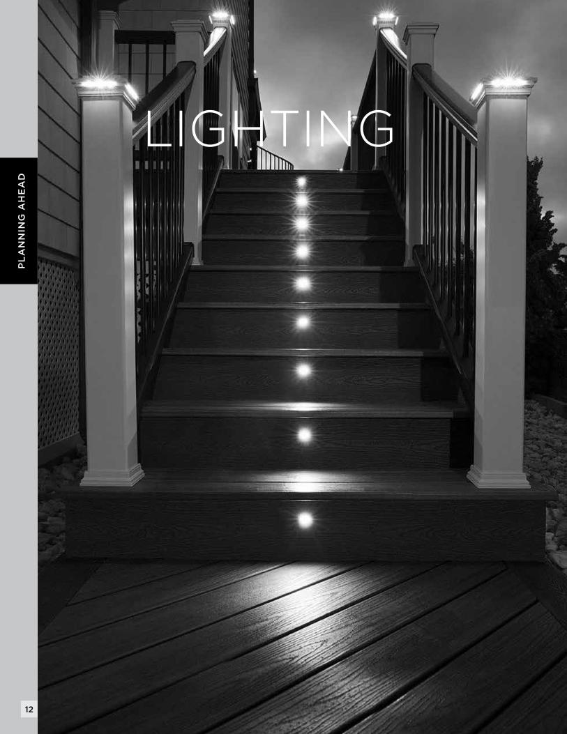
LIGHTING
13
LIG
HT
ING
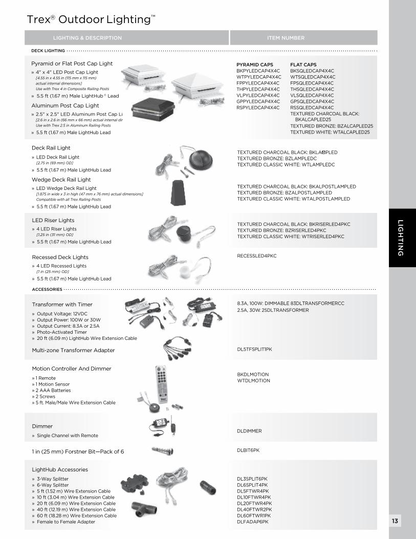
LIGHTINGPyramid or Flat Post Cap Light
» 4" x 4" LED Post Cap Light [4.55 in x 4.55 in (115 mm x 115 mm) actual internal dimensions] Use with Trex 4 in Composite Railing Posts
» 5.5 ft (1.67 m) Male LightHub ® Lead
Aluminum Post Cap Light
» 2.5" x 2.5" LED Aluminum Post Cap Light [2.6 in x 2.6 in (66 mm x 66 mm) actual internal dimensions] Use with Trex 2.5 in Aluminum Railing Posts
» 5.5 ft (1.67 m) Male LightHub Lead
LED Riser Lights
» 4 LED Riser Lights [1.25 in (31 mm) OD]
» 5.5 ft (1.67 m) Male LightHub Lead
Dimmer
» Single Channel with Remote
1 in (25 mm) Forstner Bit—Pack of 6
Recessed Deck Lights
» 4 LED Recessed Lights [1 in (25 mm) OD]
» 5.5 ft (1.67 m) Male LightHub Lead
Transformer with Timer
» Output Voltage: 12VDC» Output Power: 100W or 30W» Output Current: 8.3A or 2.5A» Photo-Activated Timer» 20 ft (6.09 m) LightHub Wire Extension Cable
Multi-zone Transformer Adapter
LightHub Accessories
» 3-Way Splitter» 6-Way Splitter» 5 ft (1.52 m) Wire Extension Cable» 10 ft (3.04 m) Wire Extension Cable» 20 ft (6.09 m) Wire Extension Cable» 40 ft (12.19 m) Wire Extension Cable» 60 ft (18.28 m) Wire Extension Cable» Female to Female Adapter
DECK LIGHTING
Deck Rail Light
» LED Deck Rail Light [2.75 in (69 mm) OD]
» 5.5 ft (1.67 m) Male LightHub Lead
Wedge Deck Rail Light
» LED Wedge Deck Rail Light [1.875 in wide x 3 in high (47 mm x 76 mm) actual dimensions] Compatible with all Trex Railing Posts
» 5.5 ft (1.67 m) Male LightHub Lead
Trex® Outdoor Lighting™
TEXTURED CHARCOAL BLACK: BKLAMPLED C TEXTURED BRONZE: BZLAMPLEDC TEXTURED CLASSIC WHITE: WTLAMPLEDC
TEXTURED CHARCOAL BLACK: BKALPOSTLAMPLED TEXTURED BRONZE: BZALPOSTLAMPLED TEXTURED CLASSIC WHITE: WTALPOSTLAMPLED
TEXTURED CHARCOAL BLACK: BKRISERLED4PKCTEXTURED BRONZE: BZRISERLED4PKCTEXTURED CLASSIC WHITE: WTRISERLED4PKC
DLDIMMER
DLBIT6PK
RECESSLED4PKC
8.3A, 100W: DIMMABLE 83DLTRANSFORMERCC
2.5A, 30W : 25DLTRANSFORMER
DL5TFSPLIT1PK
DL3SPLIT6PKDL6SPLIT4PKDL5FTWR4PKDL10FTWR4PKDL20FTWR4PKDL40FTWR2PKDL60FTWR1PKDLFADAP6PK
PYRAMID CAPS BKPYLEDCAP4X4CWTPYLEDCAP4X4CFPPYLEDCAP4X4CTHPYLEDCAP4X4CVLPYLEDCAP4X4CGPPYLEDCAP4X4CRSPYLEDCAP4X4C
FLAT CAPS BKSQLEDCAP4X4CWTSQLEDCAP4X4CFPSQLEDCAP4X4CTHSQLEDCAP4X4CVLSQLEDCAP4X4CGPSQLEDCAP4X4CRSSQLEDCAP4X4C TEXTURED CHARCOAL BLACK: BKALCAPLED25
TEXTURED BRONZE: BZALCAPLED25TEXTURED WHITE: WTALCAPLED25
ACCESSORIES
LIGHTING & DESCRIPTION ITEM NUMBER
Motion Controller And Dimmer
» 1 Remote » 1 Motion Sensor » 2 AAA Batteries » 2 Screws » 5 ft. Male/Male Wire Extension Cable
BKDLMOTION WTDLMOTION
14
LIG
HT
ING
A
B
C
D
E
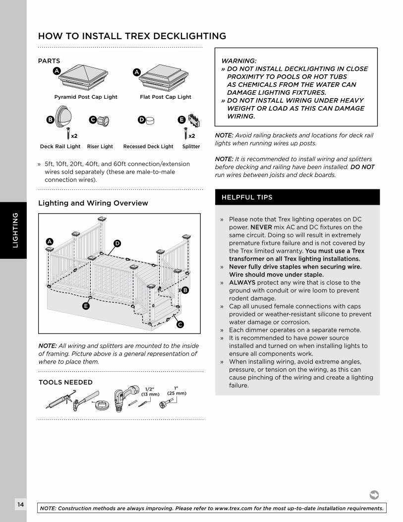
HOW TO INSTALL TREX DECKLIGHTING
PARTS
A
B C D
x2x2 x2x2 x2x2x2x2
A
Pyramid Post Cap Light
Riser Light SplitterDeck Rail Light Recessed Deck Light
B C D E
x2x2 x2x2
Flat Post Cap Light
NOTE: Allwiringandsplittersaremountedtotheinsideofframing.Pictureaboveisageneralrepresentationofwheretoplacethem.
WARNING: » DO NOT INSTALL DECKLIGHTING IN CLOSE
PROXIMITY TO POOLS OR HOT TUBS AS CHEMICALS FROM THE WATER CAN DAMAGE LIGHTING FIXTURES.
» DO NOT INSTALL WIRING UNDER HEAVY WEIGHT OR LOAD AS THIS CAN DAMAGE WIRING.
Lighting and Wiring Overview
1/2" (13 mm)
1" (25 mm)
TOOLS NEEDED
» 5ft, 10ft, 20ft, 40ft, and 60ft connection/extension wires sold separately (these are male-to-male connection wires).
HELPFUL TIPS
» Please note that Trex lighting operates on DC power. NEVER mix AC and DC fixtures on the same circuit. Doing so will result in extremely premature fixture failure and is not covered by the Trex limited warranty. You must use a Trex transformer on all Trex lighting installations.
» Never fully drive staples when securing wire. Wire should move under staple.» ALWAYS protect any wire that is close to the
ground with conduit or wire loom to prevent rodent damage.
» Cap all unused female connections with caps provided or weather-resistant silicone to prevent water damage or corrosion.
» Each dimmer operates on a separate remote.» It is recommended to have power source
installed and turned on when installing lights to ensure all components work.
» When installing wiring, avoid extreme angles, pressure, or tension on the wiring, as this can cause pinching of the wiring and create a lighting failure.
NOTE: Avoidrailingbracketsandlocationsfordeckraillightswhenrunningwiresupposts.
NOTE: Itisrecommendedtoinstallwiringandsplittersbeforedeckingandrailinghavebeeninstalled.DO NOTrunwiresbetweenjoistsanddeckboards.
NOTE: Construction methods are always improving. Please refer to www.trex.com for the most up-to-date installation requirements.
15
LIG
HT
ING
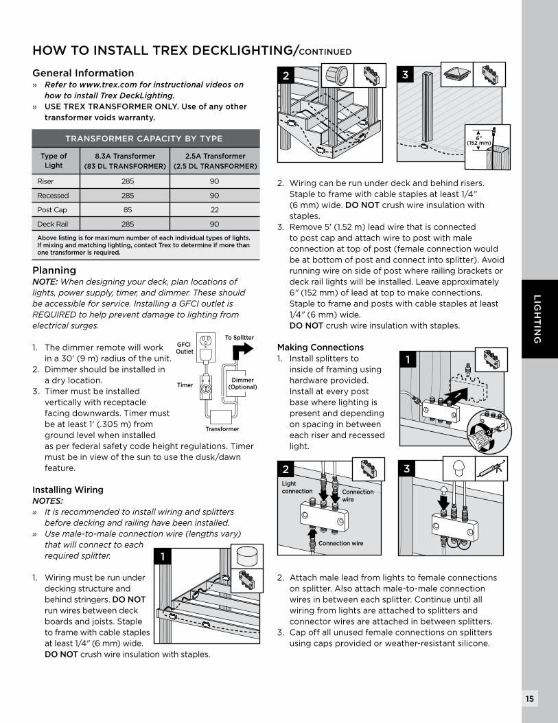
General Information » Refer to www.trex.com for instructional videos on
how to install Trex DeckLighting.» USE TREX TRANSFORMER ONLY. Use of any other
transformer voids warranty.
Planning NOTE: Whendesigningyourdeck,planlocationsoflights,powersupply,timer,anddimmer.Theseshouldbeaccessibleforservice.InstallingaGFCIoutletisREQUIREDtohelppreventdamagetolightingfromelectricalsurges.
1. The dimmer remote will work in a 30' (9 m) radius of the unit.
2. Dimmer should be installed in a dry location.
3. Timer must be installed vertically with receptacle facing downwards. Timer must be at least 1' (.305 m) from ground level when installed as per federal safety code height regulations. Timer must be in view of the sun to use the dusk/dawn feature.
Installing WiringNOTES:» Itisrecommendedtoinstallwiringandsplitters beforedeckingandrailinghavebeeninstalled.» Usemale-to-maleconnectionwire(lengthsvary)
thatwillconnecttoeachrequiredsplitter.
1. Wiring must be run under decking structure and behind stringers. DO NOT run wires between deck boards and joists. Staple to frame with cable staples at least 1/4" (6 mm) wide. DO NOT crush wire insulation with staples.
2. Wiring can be run under deck and behind risers. Staple to frame with cable staples at least 1/4" (6 mm) wide. DO NOT crush wire insulation with staples.
3. Remove 5' (1.52 m) lead wire that is connected to post cap and attach wire to post with male connection at top of post (female connection would be at bottom of post and connect into splitter). Avoid running wire on side of post where railing brackets or deck rail lights will be installed. Leave approximately 6" (152 mm) of lead at top to make connections. Staple to frame and posts with cable staples at least 1/4" (6 mm) wide. DO NOT crush wire insulation with staples.
Making Connections1. Install splitters to
inside of framing using hardware provided. Install at every post base where lighting is present and depending on spacing in between each riser and recessed light.
2. Attach male lead from lights to female connections on splitter. Also attach male-to-male connection wires in between each splitter. Continue until all wiring from lights are attached to splitters and connector wires are attached in between splitters.
3. Cap off all unused female connections on splitters using caps provided or weather-resistant silicone.
HOW TO INSTALL TREX DECKLIGHTING/CONTINUED
GFCI Outlet
Timer
Transformer
To Splitter
Dimmer(Optional)
1
3
6"(152 mm)
1
1
2
2Lightconnection Connection
wire
Connection wire
3
2
TRANSFORMER CAPACITY BY TYPE
8.3A Transformer
(83 DL TRANSFORMER)
Type ofLight
2.5A Transformer
(2.5 DL TRANSFORMER)
Riser 285 90
Recessed 285 90
Post Cap 85 22
Deck Rail 285 90
Above listing is for maximum number of each individual types of lights. If mixing and matching lighting, contact Trex to determine if more than one transformer is required.
16
LIG
HT
ING
HOW TO INSTALL TREX DECKLIGHTING/CONTINUED
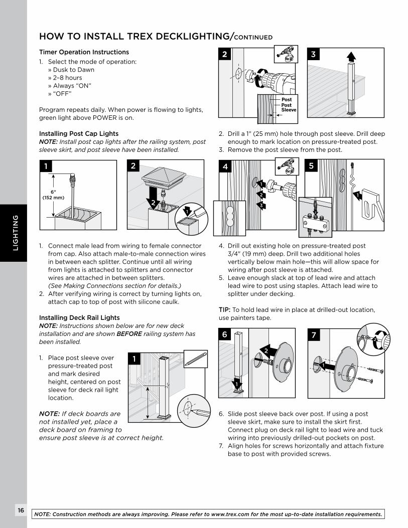
Timer Operation Instructions
1. Select the mode of operation: » Dusk to Dawn » 2–8 hours » Always “ON” » “OFF”
Program repeats daily. When power is flowing to lights, green light above POWER is on.
Installing Post Cap LightsNOTE: Installpostcaplightsaftertherailingsystem,postsleeveskirt,andpostsleevehavebeeninstalled.
1. Connect male lead from wiring to female connector from cap. Also attach male-to-male connection wires in between each splitter. Continue until all wiring from lights is attached to splitters and connector wires are attached in between splitters. (SeeMakingConnectionssectionfordetails.)
2. After verifying wiring is correct by turning lights on, attach cap to top of post with silicone caulk.
Installing Deck Rail Lights NOTE: InstructionsshownbelowarefornewdeckinstallationandareshownBEFORErailingsystemhasbeeninstalled.
1. Place post sleeve over pressure-treated post and mark desired height, centered on post sleeve for deck rail light location.
NOTE:Ifdeckboardsarenotinstalledyet,placeadeckboardonframingtoensurepostsleeveisatcorrectheight.
2. Drill a 1" (25 mm) hole through post sleeve. Drill deep enough to mark location on pressure-treated post.
3. Remove the post sleeve from the post.
4. Drill out existing hole on pressure-treated post 3/4" (19 mm) deep. Drill two additional holes vertically below main hole—this will allow space for wiring after post sleeve is attached.
5. Leave enough slack at top of lead wire and attach lead wire to post using staples. Attach lead wire to splitter under decking.
TIP: To hold lead wire in place at drilled-out location, use painters tape.
6. Slide post sleeve back over post. If using a post sleeve skirt, make sure to install the skirt first. Connect plug on deck rail light to lead wire and tuck wiring into previously drilled-out pockets on post.
7. Align holes for screws horizontally and attach fixture base to post with provided screws.
2
2
3
1
6"(152 mm)
1
1
2
PostPost Sleeve
3
1
2
3
4
1
5
2
2
1
6
1
72
NOTE: Construction methods are always improving. Please refer to www.trex.com for the most up-to-date installation requirements.
17
LIG
HT
ING
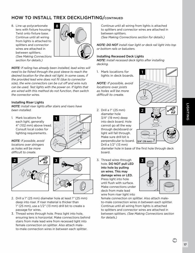
8. Line up polycarbonate lens with fixture housing. Twist onto fixture base. Continue until all wiring from lights is attached to splitters and connector wires are attached in between splitters. (SeeMakingConnectionssectionfordetails.)
NOTE: Ifrailinghasalreadybeeninstalled,leadwireswillneedtobefishedthroughthepostsleevetoreachthedesiredlocationforthedeckraillight.Insomecases,iftheprovidedleadwiredoesnotfit(duetoconnectorsize),thewireconnectorscanbecutoffandwirenutscanbeused.Testlightswiththepoweron.Iflightsthatarewiredwiththismethoddonotfunction,thenswitchtheconnectorwires.
Installing Riser LightsNOTE:Installriserlightsafterstairsandrisershavebeeninstalled.
1. Mark locations for each light, generally 4" (102 mm) above tread. Consult local codes for lighting requirements.
NOTE:Ifpossible,avoidlocationsoverstringersasholeswillbemoredifficulttocreate.
2. Drill a 1" (25 mm) diameter hole at least 1" (25 mm) deep into riser. If riser material is thicker than 1" (25 mm), use a 1/2" (13 mm) drill bit to create a passage for wires.
3. Thread wires through hole. Press light into hole, ensuring lens is horizontal. Make connections behind stairs from male lead wire from recessed light into female connection on splitter. Also attach male-to-male connection wires in between each splitter.
Continue until all wiring from lights is attached to splitters and connector wires are attached in between splitters. (SeeMakingConnectionssectionfordetails.)
NOTE: DO NOT installriserlightordeckraillightintotoporbottomrailsorbalusters.Installing Recessed Deck Lights NOTE: Installrecesseddecklightsafterinstallingdecking.
1. Mark locations for lights in deck boards.
NOTE: Ifpossible,avoidlocationsoverjoistsasholeswillbemoredifficulttocreate.
2. Drill a 1" (25 mm) diameter hole 3/4" (19 mm) deep into deck board. Hole cannot go all the way through deckboard or light will fall through. Make sure drill bit is perpendicular to board. Drill a 1/2" (13 mm) diameter hole in base of the first hole through deck board.
3. Thread wires through hole. DO NOT pull LED into hole by pulling on wires. This may damage wires or LED. Press light into hole until flush with surface. Make connections under deck from male lead wire from riser light into female connection on splitter. Also attach male-to-male connection wires in between each splitter. Continue until all wiring from lights is attached to splitters and connector wires are attached in between splitters. (SeeMakingConnectionssectionfordetails.)
1
8
2
HOW TO INSTALL TREX DECKLIGHTING/CONTINUED
4"(102 mm)
4"(102 mm)
1
21
2
3
1
2
1
3
1
2
2
3/4" (19 mm)
18
LIG
HT
ING
NOTE: Construction methods are always improving. Please refer to www.trex.com for the most up-to-date installation requirements.
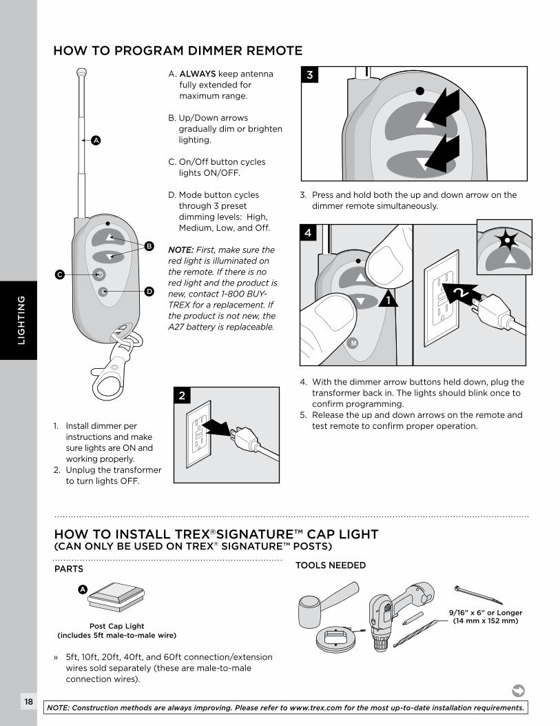
A. ALWAYS keep antenna fully extended for maximum range.
B. Up/Down arrows gradually dim or brighten lighting.
C. On/Off button cycles lights ON/OFF.
D. Mode button cycles through 3 preset dimming levels: High, Medium, Low, and Off.
NOTE: First,makesuretheredlightisilluminatedontheremote.Ifthereisnoredlightandtheproductisnew,contact1-800BUY-TREXforareplacement.Iftheproductisnotnew,theA27batteryisreplaceable.
1. Install dimmer per instructions and make sure lights are ON and working properly.
2. Unplug the transformer to turn lights OFF.
3. Press and hold both the up and down arrow on the dimmer remote simultaneously.
4. With the dimmer arrow buttons held down, plug the transformer back in. The lights should blink once to confirm programming.
5. Release the up and down arrows on the remote and test remote to confirm proper operation.
HOW TO PROGRAM DIMMER REMOTE
2
3
4
1 2
A
B
C
D
HOW TO INSTALL TREX®SIGNATURE™ CAP LIGHT(CAN ONLY BE USED ON TREX® SIGNATURE™ POSTS)
PARTS
A
Post Cap Light(includes 5ft male-to-male wire)
9/16" x 6" or Longer(14 mm x 152 mm)
TOOLS NEEDED
» 5ft, 10ft, 20ft, 40ft, and 60ft connection/extension wires sold separately (these are male-to-male connection wires).
19
LIG
HT
ING
HOW TO INSTALL TREX®SIGNATURE™ CAP LIGHT/CONTINUED(CAN ONLY BE USED ON TREX® SIGNATURE™ POSTS)
HELPFUL TIPS
» Leave slack in wire to make fixture terminations.» Post lamps work well at changes in levels of a
deck—at the top or the bottom of the stairs, or in conjunction with post cap lights.
» Splitters should be used at each post that has lights and depending on spacing in between each riser and recessed light.
» Cap all unused female connections with caps provided or weather-resistant silicone to prevent water damage or corrosion.
» The splitter is cross-linked so there is no specified plug for lights versus lead wires.
» Leads attached to each light are approx. 5.5' (1.67 m) in length and have male terminals to plug into splitter.
» Use a separate dimmer control for each light type for maximum control.
» It is recommended to have power source on when installing lights to ensure all components work.
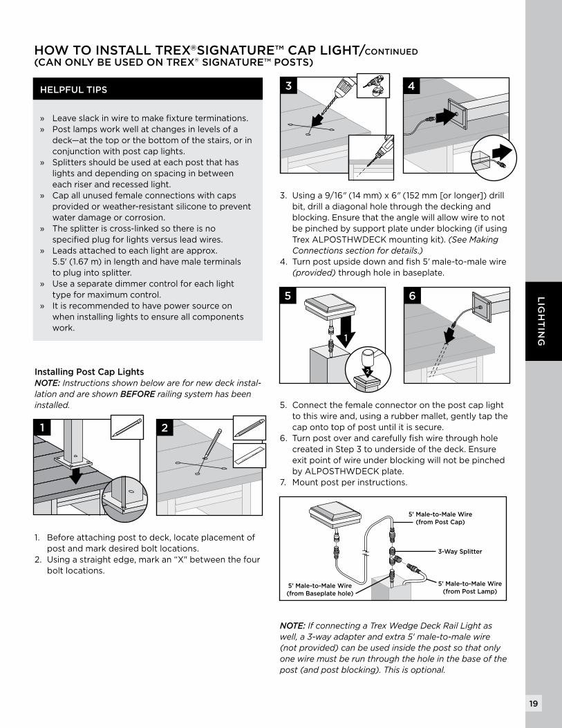
Installing Post Cap LightsNOTE:Instructionsshownbelowarefornewdeckinstal-lationandareshownBEFORErailingsystemhasbeeninstalled.
1. Before attaching post to deck, locate placement of post and mark desired bolt locations.
2. Using a straight edge, mark an “X" between the four bolt locations.
1
3
2
4
3. Using a 9/16" (14 mm) x 6" (152 mm [or longer]) drill bit, drill a diagonal hole through the decking and blocking. Ensure that the angle will allow wire to not be pinched by support plate under blocking (if using Trex ALPOSTHWDECK mounting kit). (SeeMakingConnectionssectionfordetails.)
4. Turn post upside down and fish 5' male-to-male wire (provided) through hole in baseplate.
5. Connect the female connector on the post cap light to this wire and, using a rubber mallet, gently tap the cap onto top of post until it is secure.
6. Turn post over and carefully fish wire through hole created in Step 3 to underside of the deck. Ensure exit point of wire under blocking will not be pinched by ALPOSTHWDECK plate.
7. Mount post per instructions.
NOTE: IfconnectingaTrexWedgeDeckRailLightaswell,a3-wayadapterandextra5'male-to-malewire(notprovided)canbeusedinsidethepostsothatonlyonewiremustberunthroughtheholeinthebaseofthepost(andpostblocking).Thisisoptional.
1
5
1
2
6
5' Male-to-Male Wire(from Post Cap)
5' Male-to-Male Wire(from Post Lamp)
5' Male-to-Male Wire(from Baseplate hole)
3-Way Splitter
20
LIG
HT
ING
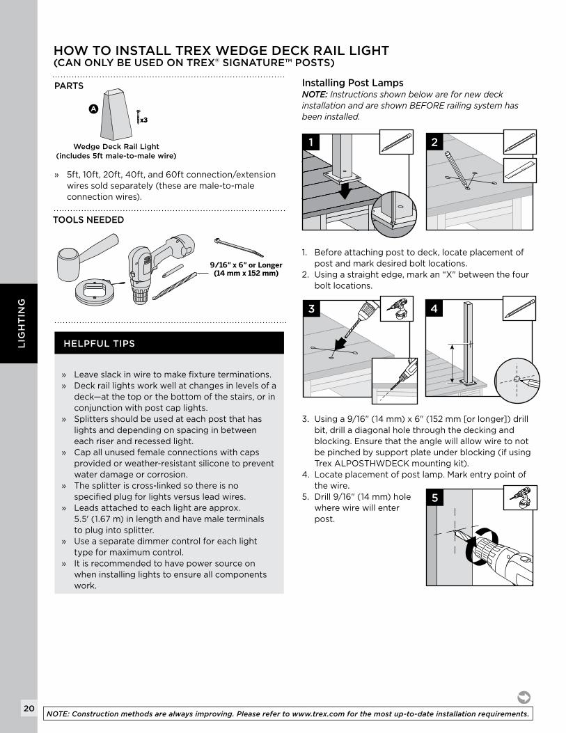
HOW TO INSTALL TREX WEDGE DECK RAIL LIGHT(CAN ONLY BE USED ON TREX® SIGNATURE™ POSTS)
PARTS
A
x3x3
Wedge Deck Rail Light(includes 5ft male-to-male wire)
9/16" x 6" or Longer(14 mm x 152 mm)
TOOLS NEEDED
» 5ft, 10ft, 20ft, 40ft, and 60ft connection/extension wires sold separately (these are male-to-male connection wires).
HELPFUL TIPS
» Leave slack in wire to make fixture terminations.» Deck rail lights work well at changes in levels of a
deck—at the top or the bottom of the stairs, or in conjunction with post cap lights.
» Splitters should be used at each post that has lights and depending on spacing in between each riser and recessed light.
» Cap all unused female connections with caps provided or weather-resistant silicone to prevent water damage or corrosion.
» The splitter is cross-linked so there is no specified plug for lights versus lead wires.
» Leads attached to each light are approx. 5.5' (1.67 m) in length and have male terminals to plug into splitter.
» Use a separate dimmer control for each light type for maximum control.
» It is recommended to have power source on when installing lights to ensure all components work.
Installing Post Lamps NOTE:InstructionsshownbelowarefornewdeckinstallationandareshownBEFORErailingsystemhasbeeninstalled.
1. Before attaching post to deck, locate placement of post and mark desired bolt locations.
2. Using a straight edge, mark an “X" between the four bolt locations.
3. Using a 9/16" (14 mm) x 6" (152 mm [or longer]) drill bit, drill a diagonal hole through the decking and blocking. Ensure that the angle will allow wire to not be pinched by support plate under blocking (if using Trex ALPOSTHWDECK mounting kit).
4. Locate placement of post lamp. Mark entry point of the wire.
5. Drill 9/16" (14 mm) hole where wire will enter post.
1
3
5
2
4
NOTE: Construction methods are always improving. Please refer to www.trex.com for the most up-to-date installation requirements.
21
LIG
HT
ING
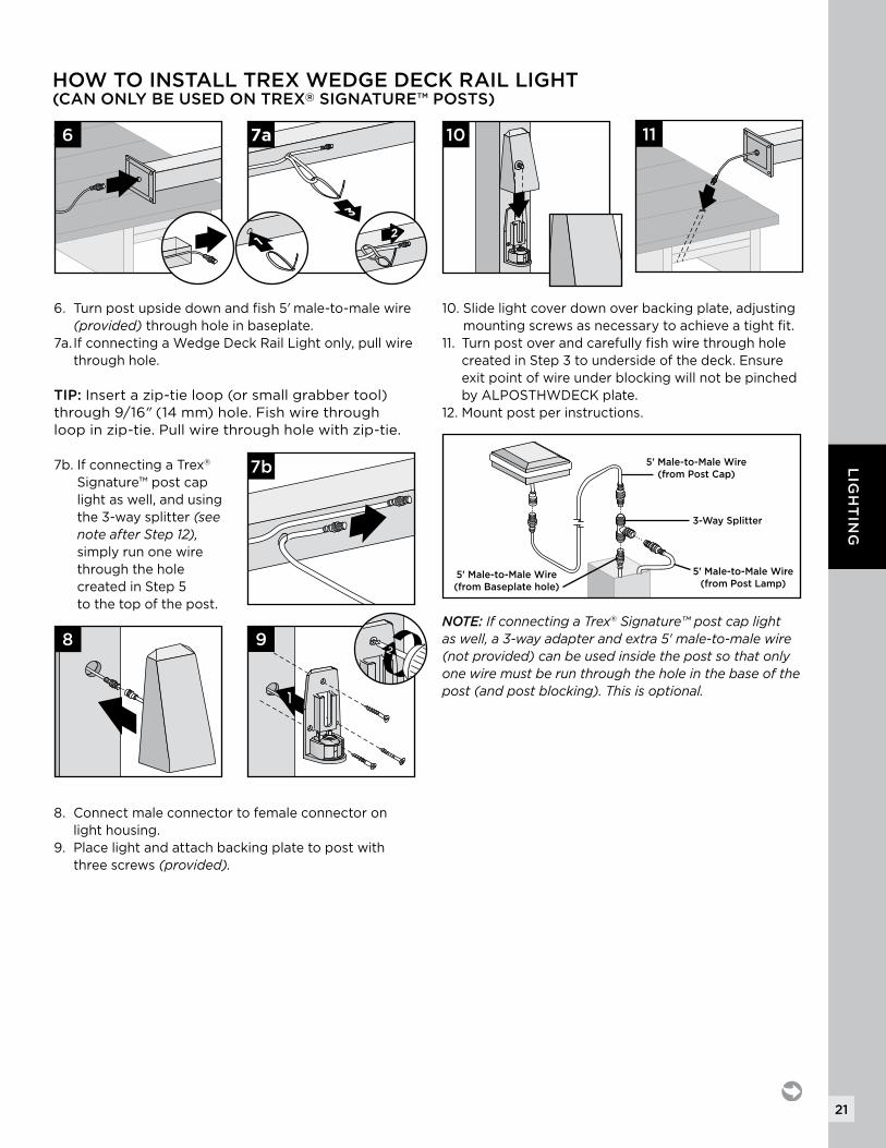
10. Slide light cover down over backing plate, adjusting mounting screws as necessary to achieve a tight fit.
11. Turn post over and carefully fish wire through hole created in Step 3 to underside of the deck. Ensure exit point of wire under blocking will not be pinched by ALPOSTHWDECK plate.
12. Mount post per instructions.
NOTE: IfconnectingaTrex®Signature™postcaplightaswell,a3-wayadapterandextra5'male-to-malewire(notprovided)canbeusedinsidethepostsothatonlyonewiremustberunthroughtheholeinthebaseofthepost(andpostblocking).Thisisoptional.
6. Turn post upside down and fish 5' male-to-male wire (provided)through hole in baseplate.
7a. If connecting a Wedge Deck Rail Light only, pull wire through hole.
TIP: Insert a zip-tie loop (or small grabber tool) through 9/16" (14 mm) hole. Fish wire through loop in zip-tie. Pull wire through hole with zip-tie.
7b. If connecting a Trex® Signature™ post cap light as well, and using the 3-way splitter (seenoteafterStep12), simply run one wire through the hole created in Step 5 to the top of the post.
8. Connect male connector to female connector on light housing.
9. Place light and attach backing plate to post with three screws (provided).
6
8
10
3
7a
12
7b 5' Male-to-Male Wire(from Post Cap)
5' Male-to-Male Wire(from Post Lamp)
5' Male-to-Male Wire(from Baseplate hole)
3-Way Splitter
1
92
11
HOW TO INSTALL TREX WEDGE DECK RAIL LIGHT(CAN ONLY BE USED ON TREX® SIGNATURE™ POSTS)
22
LIG
HT
ING
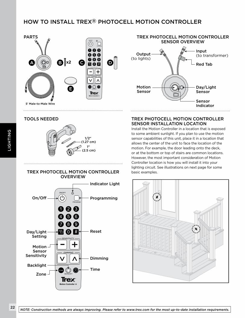
HOW TO INSTALL TREX® PHOTOCELL MOTION CONTROLLER
TREX PHOTOCELL MOTION CONTROLLER OVERVIEW
TOOLS NEEDED
PARTS
x2x2A B C D
E
5' Male-to-Male Wire
1/2" (1.27 cm)
1" (2.5 cm)
TREX PHOTOCELL MOTION CONTROLLER SENSOR INSTALLATION LOCATION Install the Motion Controller in a location that is exposed to some ambient sunlight. If you plan to use the motion sensor capabilities of this unit, place it in a location that allows the center of the unit to face the location of the motion. For example, the door leading onto the deck, or at the bottom or top of stairs are common locations. However, the most important consideration of Motion Controller location is how you will install it into your lighting circuit. See illustrations on next page for some basic examples.
TREX PHOTOCELL MOTION CONTROLLER SENSOR OVERVIEW
Input (to transformer)Output
(to lights)
Red Tab
SensorIndicator
Day/Light Sensor
MotionSensor
Indicator Light
Programming
Reset
Time
Dimming
Day/LightSetting
MotionSensor
Sensitivity
On/Off
Backlight
Zone
NOTE: Construction methods are always improving. Please refer to www.trex.com for the most up-to-date installation requirements.
23
LIG
HT
ING
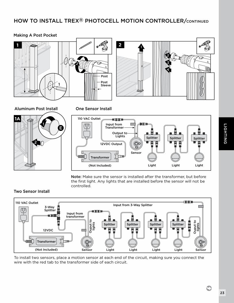
One Sensor Install
110 VAC Outlet
12VDC Output
Output to Lights
Input from Transformer
LightLightLight
Sensor
SplitterSplitter Splitter
Transformer
(Not Included)
Making A Post Pocket
2
1
Post
Post Sleeve1
2
3
4
12
Two Sensor Install
Note: Make sure the sensor is installed after the transformer, but before the first light. Any lights that are installed before the sensor will not be controlled.
110 VAC Outlet
Sensor Sensor
SplitterSplitterSplitter
Light Light Light Light
Splitter
12VDC
Ou
pu
t to
lig
hts
3-Way Splitter
Transformer
(Not Included)
Input from 3-Way Splitter
Input from transformer
Ou
pu
t to
lig
hts
To install two sensors, place a motion sensor at each end of the circuit, making sure you connect the wire with the red tab to the transformer side of each circuit.
Aluminum Post Install
1A
E1
2
HOW TO INSTALL TREX® PHOTOCELL MOTION CONTROLLER/CONTINUED
24
LIG
HT
ING
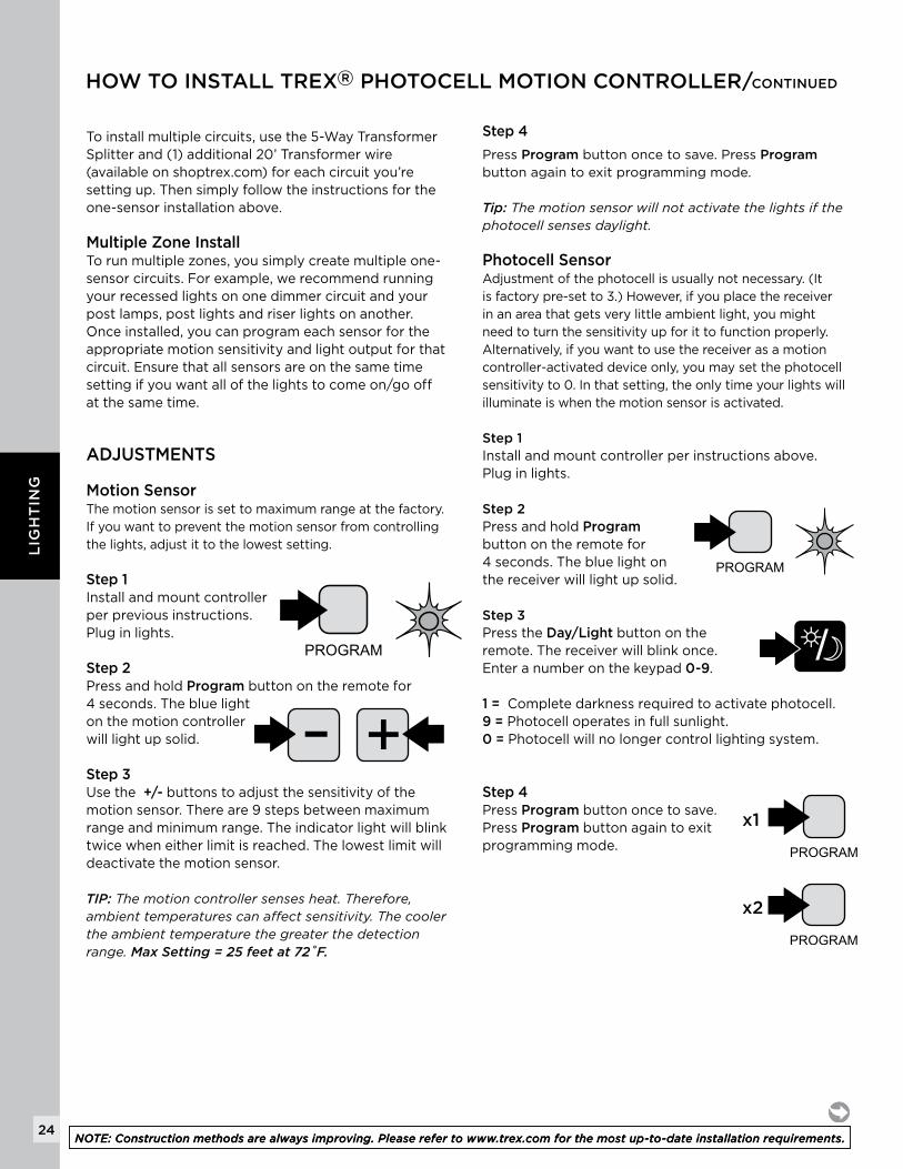
To install multiple circuits, use the 5-Way Transformer Splitter and (1) additional 20’ Transformer wire (available on shoptrex.com) for each circuit you’re setting up. Then simply follow the instructions for the one-sensor installation above.
Multiple Zone InstallTo run multiple zones, you simply create multiple one-sensor circuits. For example, we recommend running your recessed lights on one dimmer circuit and your post lamps, post lights and riser lights on another. Once installed, you can program each sensor for the appropriate motion sensitivity and light output for that circuit. Ensure that all sensors are on the same time setting if you want all of the lights to come on/go off at the same time.
Motion Sensor The motion sensor is set to maximum range at the factory. If you want to prevent the motion sensor from controlling the lights, adjust it to the lowest setting.
Step 1Install and mount controller per previous instructions. Plug in lights.
Step 2Press and hold Program button on the remote for 4 seconds. The blue light on the motion controller will light up solid.
Step 3Use the +/- buttons to adjust the sensitivity of the motion sensor. There are 9 steps between maximum range and minimum range. The indicator light will blink twice when either limit is reached. The lowest limit will deactivate the motion sensor.
TIP: Themotioncontrollersensesheat.Therefore,ambienttemperaturescanaffectsensitivity.Thecoolertheambienttemperaturethegreaterthedetectionrange.Max Setting = 25 feet at 72˚F.
ADJUSTMENTS
x1
x2
x1
x2
Step 4
Press Program button once to save. Press Program button again to exit programming mode.
Tip: Themotionsensorwillnotactivatethelightsifthephotocellsensesdaylight.
Photocell Sensor Adjustment of the photocell is usually not necessary. (It is factory pre-set to 3.) However, if you place the receiver in an area that gets very little ambient light, you might need to turn the sensitivity up for it to function properly. Alternatively, if you want to use the receiver as a motion controller-activated device only, you may set the photocell sensitivity to 0. In that setting, the only time your lights will illuminate is when the motion sensor is activated.
Step 1Install and mount controller per instructions above. Plug in lights.
Step 2Press and hold Program button on the remote for 4 seconds. The blue light on the receiver will light up solid.
Step 3Press the Day/Light button on the remote. The receiver will blink once. Enter a number on the keypad 0-9. 1 = Complete darkness required to activate photocell.9 = Photocell operates in full sunlight. 0 = Photocell will no longer control lighting system.
Step 4Press Program button once to save. Press Program button again to exit programming mode.
x1
x2
x1
x2
x1
x2
NOTE: Construction methods are always improving. Please refer to www.trex.com for the most up-to-date installation requirements. NOTE: Construction methods are always improving. Please refer to www.trex.com for the most up-to-date installation requirements.
HOW TO INSTALL TREX® PHOTOCELL MOTION CONTROLLER/CONTINUED
25
LIG
HT
ING
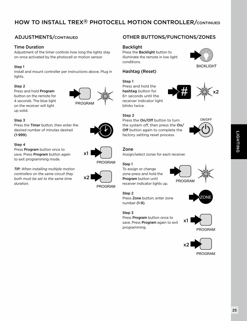
ADJUSTMENTS/CONTINUED
Time Duration Adjustment of the timer controls how long the lights stay on once activated by the photocell or motion sensor. Step 1 Install and mount controller per instructions above. Plug in lights. Step 2 Press and hold Program button on the remote for 4 seconds. The blue light on the receiver will light up solid.
Step 3 Press the Timer button, then enter the desired number of minutes desired (1-999).
Step 4 Press Program button once to save. Press Program button again to exit programming mode.
TIP:Wheninstallingmultiplemotioncontrollersonthesamecircuittheybothmustbesettothesametimeduration.
Backlight Press the Backlight button to illuminate the remote in low light conditions. Hashtag (Reset)
Step 1 Press and hold the hashtag button for6+ seconds until the receiver indicator light blinks twice.
Step 2Press the On/Off button to turn the system off, then press the On/Off button again to complete the factory setting reset process.
Zone Assign/select zones for each receiver. Step 1 To assign or change zone press and hold the Program button until receiver indicator lights up.
Step 2 Press Zone button; enter zone number (1-9).
Step 3 Press Program button once to save. Press Program again to exit programming.
x1
x2
x1
x2
x1
x2
OTHER BUTTONS/FUNCTIONS/ZONES
x1
x2x1
x2
x2
x1
x2
x2
x1
x2
x2
x1
x2
x2
x1
x2
x2
HOW TO INSTALL TREX® PHOTOCELL MOTION CONTROLLER/CONTINUED