lightmachinery test report lqt 30.11-3 - stanford...
TRANSCRIPT

LQT 30.11-3, Rev A
Page 1 of 34
LIGHTMACHINERY TEST REPORT
LQT 30.11-3
TITLE: HMI Michelson Interferometer Test Report Serial Number 3 – wide band FSR
INSTRUCTION OWNER HMI Project Manager
PREPARED BY: I. Miller DATE: 2004 May 23 CO-OWNERS
APPROVED BY I MILLER
QUALITY ASSURANCE: R. Weeks
REVISED DATE OF ISSUE/CHANGED PAGES
REVISION RELEASE DATE CHANGED PAGES/NOTES
NR 2006 Jan 31 Initial creation
A 2006 Feb 3 First release
Note: All documentation is subject to change, and therefore you must check the company data base for the current Document Revision.

LQT 30.11-3, Rev A
Page 2 of 34
Table of Contents 1.0 PURPOSE and SCOPE..............................................................................4
2.0 DOCUMENTATION....................................................................................4
3.0 TEST RESULTS............................................................................................6 PERFORMANCE SUMMARY ....................................................................................... 6 FREE SPECTRAL RANGE (3.1) .................................................................................. 7 TRANSMISSION AND CONTRAST (3.2) ....................................................................... 8 PVA POLARIZER UNIFORMITY ................................................................................. 9 CLEAR APERTURE (3.3) ......................................................................................... 10 BEAM ORTHOGONALITY (3.4) ................................................................................ 10 SPATIAL VARIATIONS OVER THE APERTURE (3.5) .................................................... 10 ANGULAR VARIATIONS OVER THE APERTURE (3.6) .................................................. 16 THIN FILM BEAM SPLITTER COATING ..................................................................... 17 TEMPERATURE DEPENDENCE (3.7) ........................................................................ 19 WAVEFRONT ERROR (3.8) ..................................................................................... 20 SURFACE FLATNESS MEASUREMENTS ................................................................... 21 ANTIREFLECTION COATINGS (3.9) .......................................................................... 23 SILVER COATINGS................................................................................................. 26 SURFACE QUALITY (3.10) ...................................................................................... 27 CEMENT (3.11) ..................................................................................................... 27 ASSEMBLY DIMENSIONS AND IDENTIFICATION (3.12) ............................................... 28 MATERIAL CERTIFICATES, PROCESS CERTIFICATIONS............................................ 32
4.0 List of Coating Witness Samples..................................................................33
LQT 30.11-3, Rev A
Page 3 of 34
List of Figures FIGURE 1: NARROW BAND MICHELSON (S/N 2), COMPLETE. KAPTON TAPE IS WRAPPED ON THE VACUUM ARM TO PROTECT THE VACUUM GLASS INTERFACES. ....................... 5 FIGURE 2: NARROW BAND MICHELSON AND MATCHING WIDE BAND MICHELSON (S/N 1) 5 FIGURE 3: CONTRAST MEASURED AFTER SILVERING OF END MIRRORS............... 8 FIGURE 4: PVA POLARIZER OPEN TRANSMISSION, UNCORRECTED FOR FRESNEL LOSSES 9 FIGURE 5: PVA POLARIZER CLOSED TRANSMISSION........................................ 10 FIGURE 6: THIN FILM POLARIZER TS SPATIAL UNIFORMITY ................................ 11 FIGURE 7: THIN FILM POLARIZER TP SPATIAL UNIFORMITY ................................ 12 FIGURE 8: PHASE VARIATION OVER APERTURE AFTER SILVERING END MIRRORS13 FIGURE 9: PHASE VARIATION OVER APERTURE AFTER SILVERING END MIRRORS WITH TILT REMOVED 14 FIGURE 10: PHASE VARIATION OVER APERTURE BEFORE SILVERING END MIRRORS15 FIGURE 11: MEASURED MICHELSON PHASE VARIATION VS. EXTERNAL ANGLE OF INCIDENCE 16 FIGURE 12: THIN FILM POLARIZER TS, VS. ANGLE IN SAGITTAL PLANE ................. 17 FIGURE 13: THIN FILM POLARIZER TP VS. SAGITTAL ANGLE................................ 18 FIGURE 14: PHASE CONTRIBUTION FROM POLARIZING BEAM SPLITTER COATING. 19 FIGURE 15: TRANSMITTED WAVEFRONT ERROR, 0.07Λ PEAK-TO-VALLEY ........... 20 FIGURE 16: INPUT/OUTPUT WAVE PLATE SURFACE FLATNESS ............................ 21 FIGURE 17: INPUT/OUTPUT POLARIZER SURFACE FLATNESS .............................. 21 FIGURE 18: VACUUM ARM WAVE PLATE EXTERNAL SURFACE FIGURE ................. 22 FIGURE 19: VACUUM ARM WAVE PLATE INTERNAL SURFACE FIGURE (AR COATED) HMI 3 22 FIGURE 20: INTERFEROGRAM OF CUBE SURFACE FACING THE VACUUM ARM ...... 23 FIGURE 21: MEASURED REFLECTIVITY OF AR “E”, APPLIED TO VACUUM ARM WAVE PLATE AND FACING CUBE FACE ........................................................................................ 24 FIGURE 22: MEASURED REFLECTIVITY OF AR “F”, APPLIED TO INPUT/OUTPUT WAVE PLATE AND POLARIZER..................................................................................................... 25 FIGURE 23: SILVER REFLECTOR COATING RUNS “G3”—BLUE LINE, APPLIED TO THE SOLID ARM, “G4”—RED LINE, APPLIED TO THE VACUUM ARM............................................. 26 FIGURE 24: INPUT/OUTPUT WAVE PLATE THICKNESS MAP.................................. 29 FIGURE 25: VACUUM ARM WAVE PLATE THICKNESS MAP.................................... 30 FIGURE 26: SOLID ARM WAVE PLATE THICKNESS MAP........................................ 31 FIGURE 27: MATERIAL CERTIFICATE FOR 35 MM THICK OHARA BSL7Y GLASS.... 32 FIGURE 28: MATERIAL CERTIFICATE FOR 50 MM THICK OHARA BSL7Y GLASS.... 32

LQT 30.11-3, Rev A
Page 4 of 34
HMI MICHELSON TEST REPORT
1.0 PURPOSE and SCOPE This test report includes detailed measurements of the components and the final performance of the narrowband HMI Michelson interferometer, Serial Number 3. The Lockheed Martin part number is 65113-2H00009-102. This report details the key measurements for the completed Michelson and sub-assemblies but does not include all measurements made in fabrication of the Michelson interferometer. This document encompasses the requirements of SDRL 05 and SDRL 06 as described in the statement of work—2H00025.
2.0 DOCUMENTATION Reference Documents
1. LightMachinery Filing cabinet M50 (QA Manager C Drive), Project binder 2. Specification for the Helioseismic & Magnetic Imager (HMI) Michelson
Interferometer Assemblies. 2H00024 Rev A, 16 October 2003—Lockheed Martin Space Systems Company
3. Statement of Work for the Helioseismic & Magnetic Imager (HMI) Michelson Interferometer Assemblies. 2H00025 Rev A, 17 October 2003—Lockheed Martin Space Systems Company
4. HMI Michelson Fabrication Plan. D-OP-1349-0—LightMachinery Inc. Reference drawings:
1. D-OP-1349-0 HMI Fabrication process 2. D-OP-1349-22 HMI beam splitter cube 3. D-OP-1349-38 HMI polarization configuration
LQT 30.11-3, Rev A
Page 5 of 34
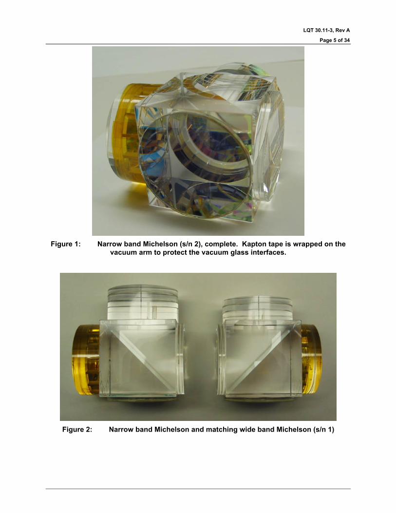
Figure 1: Narrow band Michelson (s/n 2), complete. Kapton tape is wrapped on the
vacuum arm to protect the vacuum glass interfaces.
Figure 2: Narrow band Michelson and matching wide band Michelson (s/n 1)

LQT 30.11-3, Rev A
Page 6 of 34
3.0 TEST RESULTS This document describes tests and measurements performed on the components and completed HMI Michelson assembly. In this section, requirements for the completed Michelsons are referenced from 2H00024 with the section number from that document. Specific test procedures are described in the test plan LQI 30.11.
Performance summary A summary of the Michelson performance is presented in the table below. More detailed results for each measurement are in later sections. PCA 74 records the variances for this instrument.
Description Specification Measurement Comment Free Spectral Range (3.1)
0.0344 nm ±5% 0.03431 nm OK
Ratio of wide band to narrow band free spectral range (3.1)
2.00 ±1% 1.995 OK
Contrast (3.2) >95% 98% average OK Transmission (3.2) >80% >82% OK Clear aperture (3.3) 32 mm 34 mm OK Beam orthogonality (3.4)
±15 arc seconds 2.5 arc seconds OK
Surface normals in plane (3.4)
< 1.0 arc second deviation
1.4 arc second maximum deviation
variance
Spatial variations over the aperture (3.5)
λ0 variations < ±0.0015 nm
±0.0028 nm variance
Angular variations over the aperture (3.6)
λ0 variations < ±0.0015 nm for rays within 3° of normal incidence
±0.0010 nm OK
Temperature dependence (3.7)
d λ0/dT <0.0010 nm/°C
0.84 pm/°C OK
Wavefront error (3.8) <0.05 wave peak-valley
0.07 wave peak-valley
variance
Antireflection coatings (3.9)
R<0.2% R<0.1% OK
Surface quality (3.10) Optical surface scratch-dig 60-40 or better
Better than 60-40
OK
Cement (3.11) Cement thickness <15 µm, visual inspection
Cement thickness < 15 µm, free from bubbles
OK
Assembly dimensions (3.12)
inspected OK

LQT 30.11-3, Rev A
Page 7 of 34
Free spectral range (3.1) The target value for the free spectral range of the wide band Michelson is 0.0344 nm. The free spectral range calculated from measured Michelson properties is .03431 nm. The table below shows the measured component thicknesses and the calculated free spectral range.
Measurement Value Solid arm length, before final reduction 6.3497 mm
Solid arm wave plate thickness 8.052 mm Reduction of solid arm prior to final assembly 44 µm
Finished solid arm thickness 14.365 mm Net glass path difference between solid arm and vacuum arm
mm
Wave plate/ solid arm cement thickness Norland 65, 0.005 mm
Vacuum arm length 4.1585 mm Vacuum arm wave plate thickness 8.052 mm
Wave plate/ vacuum arm cement layer Norland 65, 0.004 mm
Refractive index of BSL7Y glass 1.51575 (from Ohara material certificate)
dn/dλ -0.03649/µm Calculated FSR
0.03431 nm <0.3% deviation is within 5% specification limit
Ratio of wide band FSR to narrow band FSR 1.995
<0.3% deviation is within 1% specification limit

LQT 30.11-3, Rev A
Page 8 of 34
Transmission and contrast (3.2) Contrast was measured with a 611.9 nm collimated laser beam by comparing the maximum and minimum transmission levels as an external polarizer was rotated. Figure 1 shows the measured contrast over the instrument aperture. The average contrast is approximately 98%, compared to the specified minimum value of 95%. The laser has a Gaussian intensity profile which degrades the signal to noise ratio at the edge of the Michelson aperture.
Figure 3: Contrast measured after silvering of end mirrors
LQT 30.11-3, Rev A
Page 9 of 34
Instrument transmission is calculated from two separate measurements: the measured transmission of the input/output polarizer and the measured reflectivity of the silver end mirrors. An allowance has also been made for misalignment of the wave plates and polarizer, based on their predicted alignment accuracy. The following table shows both the transmission and contrast data.
Measurement Value Specification comment Silver mirror reflectivity >97% 95% Polarizer transmission >90% Transmission (3.2) >80% >82% OK Contrast 98% average 95% OK
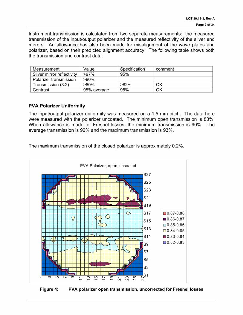
PVA Polarizer Uniformity The input/output polarizer uniformity was measured on a 1.5 mm pitch. The data here were measured with the polarizer uncoated. The minimum open transmission is 83%. When allowance is made for Fresnel losses, the minimum transmission is 90%. The average transmission is 92% and the maximum transmission is 93%. The maximum transmission of the closed polarizer is approximately 0.2%.
1 3 5 7 9 11 13 15 17 19 21 23 25 27
S1
S3
S5
S7
S9
S11
S13
S15
S17
S19
S21
S23
S25
S27
PVA Polarizer, open, uncoated
0.87-0.880.86-0.870.85-0.860.84-0.850.83-0.840.82-0.83
Figure 4: PVA polarizer open transmission, uncorrected for Fresnel losses

LQT 30.11-3, Rev A
Page 10 of 34
1 3 5 7 9 11 13 15 17 19 21 23 25 27
S1
S3
S5
S7
S9
S11
S13
S15
S17
S19
S21
S23
S25
S27
PVA polarizer, closed
0.0019-0.0020.0018-0.00190.0017-0.00180.0016-0.00170.0015-0.0016
Figure 5: PVA polarizer closed transmission
Clear aperture (3.3) The clear aperture is 34 mm, limited by the AR coatings on the vacuum arm.
Beam Orthogonality (3.4) The cube faces are made square to 1 arc second. After cementing, all external faces were measured to be within 1.4 seconds of perpendicular relative to their respective faces.
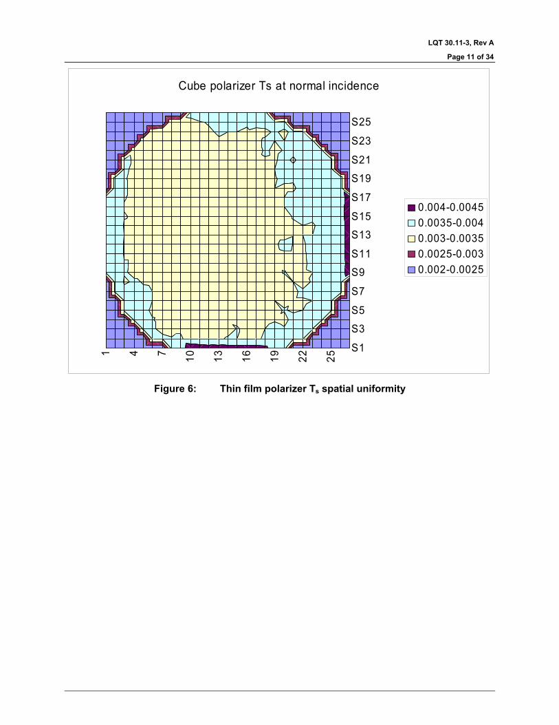
Spatial variations over the aperture (3.5) Beamsplitter coating uniformity is shown in Figure 6 and Figure 7 below. This data was collected on a 1.5 mm x 1.5 mm grid.
LQT 30.11-3, Rev A
Page 11 of 34
1 4 7 10 13 16 19 22 25S1
S3
S5
S7
S9
S11
S13
S15
S17
S19
S21
S23
S25
Cube polarizer Ts at normal incidence
0.004-0.00450.0035-0.0040.003-0.00350.0025-0.0030.002-0.0025
Figure 6: Thin film polarizer Ts spatial uniformity

LQT 30.11-3, Rev A
Page 12 of 34
1 4 7 10 13 16 19 22 25S1S3S5S7
S9S11S13
S15S17S19
S21S23S25S27
Cube polarizer Tp at normal incidence
0.996-10.992-0.9960.988-0.9920.984-0.9880.98-0.9840.976-0.980.972-0.9760.968-0.9720.964-0.9680.96-0.964
Figure 7: Thin film polarizer Tp spatial uniformity
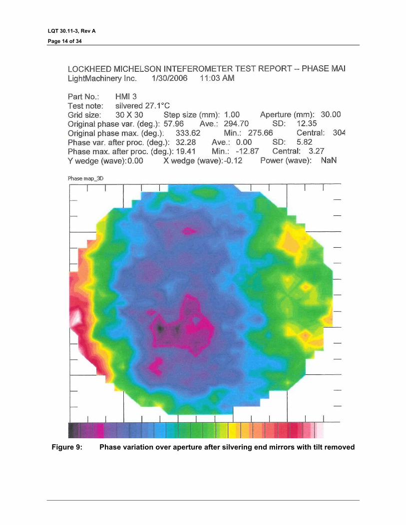
Data shown below were taken with phase averaging over a 0.3 mm x 0.3 mm pixel. The measured λ0 variation is ±0.0028 nm peak-valley compared to the specification of ±0.0015 nm. Standard deviation (single sided) for the λ0 variation is 0.0012 nm. Approximately 50% of the total phase error is due to wedge in the assembly. Hand written numbers for wedge and power show the contributions of these particular errors to the measured error. This instrument is sensitive to temperature gradients and fluctuations. Temperature changes in the test room have a strong influence on the performance of the instrument, and the total phase uniformity should be rechecked once the Michelson is mounted in a temperature controlled oven. Prior to silvering the total phase variation was approximately ±0.0017 nm. The phase variation of the other three Michelsons was not significantly affected by the silvering process, and as a consequence, the change in phase variation after silvering is thought to be due to the change in ambient test conditions. It is not known whether the before or after silvering environment is closer to ideal. All previous phase testing was performed with the clean bench in the test room. The large fan on the clean bench had several possible effects on the test room. First it increased the room temperature by 1-2° C. This change should not be significant. The second effect of the clean bench is to

LQT 30.11-3, Rev A
Page 13 of 34
mix the air in the room more thoroughly than with the normal building ventilation. Finally, the clean bench raises the temperature of the air, and directs this stream of warm air toward the Michelson test set up.
Figure 8: Phase variation over aperture after silvering end mirrors
LQT 30.11-3, Rev A
Page 14 of 34
Figure 9: Phase variation over aperture after silvering end mirrors with tilt removed

LQT 30.11-3, Rev A
Page 15 of 34
Figure 10: Phase variation over aperture before silvering end mirrors
LQT 30.11-3, Rev A
Page 16 of 34
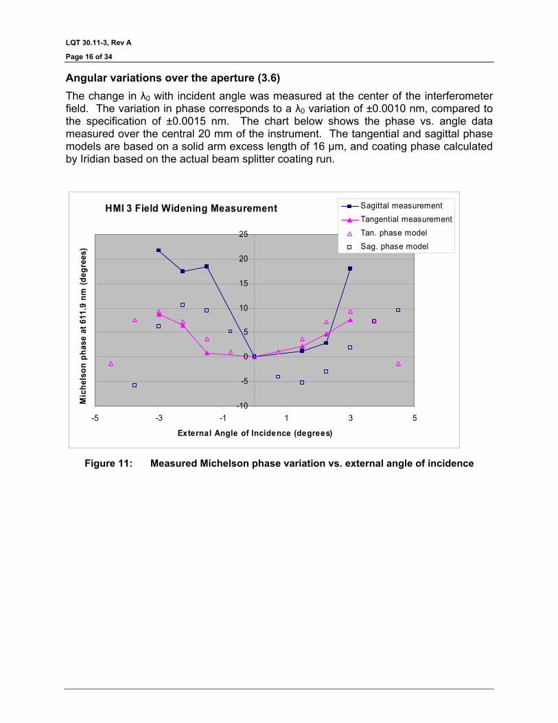
Angular variations over the aperture (3.6) The change in λ0 with incident angle was measured at the center of the interferometer field. The variation in phase corresponds to a λ0 variation of ±0.0010 nm, compared to the specification of ±0.0015 nm. The chart below shows the phase vs. angle data measured over the central 20 mm of the instrument. The tangential and sagittal phase models are based on a solid arm excess length of 16 µm, and coating phase calculated by Iridian based on the actual beam splitter coating run.
HMI 3 Field Widening Measurement
-10
-5
0
5
10
15
20
25
-5 -3 -1 1 3 5
External Angle of Incidence (degrees)
Mic
hels
on p
hase
at 6
11.9
nm
(deg
rees
)
Sagittal measurementTangential measurementTan. phase modelSag. phase model
Figure 11: Measured Michelson phase variation vs. external angle of incidence
LQT 30.11-3, Rev A
Page 17 of 34
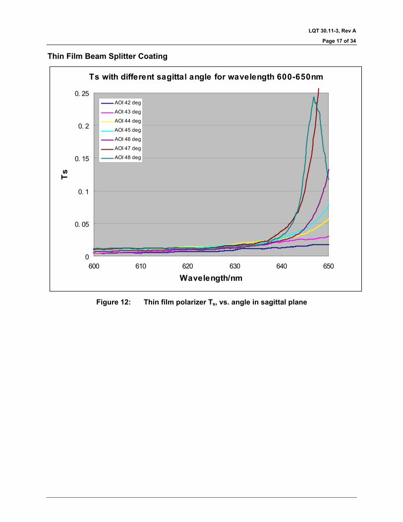
Thin Film Beam Splitter Coating
Ts with different sagittal angle for wavelength 600-650nm
0
0. 05
0. 1
0. 15
0. 2
0. 25
600 610 620 630 640 650
Wavelength/nm
Ts
AOI 42 deg
AOI 43 deg
AOI 44 deg
AOI 45 deg
AOI 46 deg
AOI 47 deg
AOI 48 deg
Figure 12: Thin film polarizer Ts, vs. angle in sagittal plane
LQT 30.11-3, Rev A
Page 18 of 34
Tp with different sagittal angle for wavelength 550-700nm
0
0.1
0.2
0.3
0.4
0.5
0.6
0.7
0.8
0.9
1
550 570 590 610 630 650 670 690
wavelength/nm
Tp
AOI 42 deg
AOI 43 deg
AOI 44 deg
AOI 45 deg
AOI 46 deg
AOI 47 deg
AOI 48 deg
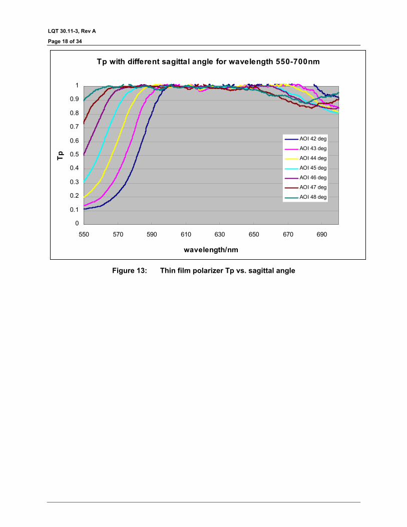
Figure 13: Thin film polarizer Tp vs. sagittal angle

LQT 30.11-3, Rev A
Page 19 of 34
Beam splitter phase contribution
-30
-25
-20
-15
-10
-5
0
5
10
15
42.0 43.0 44.0 45.0 46.0 47.0 48.0
Beam splitter angle of incidence (degrees)
Net
pha
se fr
om b
eam
spl
itter
(deg
rees
)
Figure 14: Phase contribution from polarizing beam splitter coating.
The beam splitter phase is calculated from monitored thin film deposition. Net phase = φRs1+φTp2-(φTp1+φRs2). Although the coating is designed to be symmetric from front to back, during the deposition process small corrections were made to optimize the coating performance resulting in slight asymmetry of the deposited coating.
Temperature dependence (3.7) The temperature dependence of the Michelson was not measured. Based on measurements made on the engineering test unit, the temperature dependence is predicted to be dλ0/dT = 0.84 pm/°C. This change is less than the maximum permissible drift of 1 pm/°C.

LQT 30.11-3, Rev A
Page 20 of 34
Wavefront error (3.8) The total wavefront error measured on the Zygo interferometer is 0.07λ peak to valley, compared to the specified value of 0.05 λ. The figure below shows the transmitted wavefront error.
Figure 15: Transmitted wavefront error, 0.07λ peak-to-valley
LQT 30.11-3, Rev A
Page 21 of 34
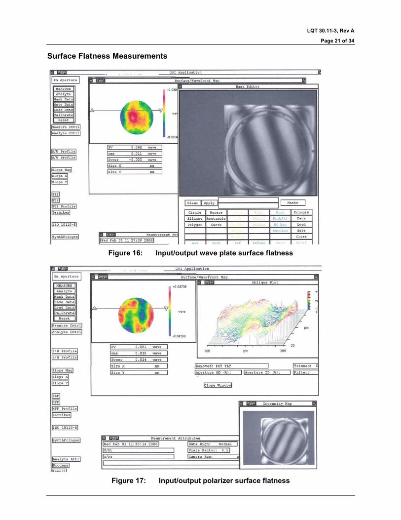
Surface Flatness Measurements
Figure 16: Input/output wave plate surface flatness
Figure 17: Input/output polarizer surface flatness
LQT 30.11-3, Rev A
Page 22 of 34
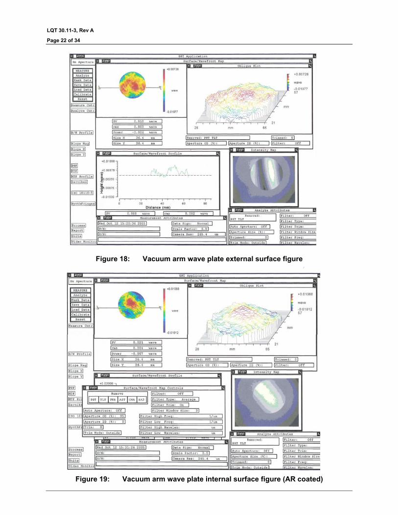
Figure 18: Vacuum arm wave plate external surface figure
Figure 19: Vacuum arm wave plate internal surface figure (AR coated)

LQT 30.11-3, Rev A
Page 23 of 34
Figure 20: Interferogram of cube surface facing the vacuum arm
Antireflection coatings (3.9) All anti-reflection coatings were measured to have a reflectivity less than 0.1% at 617.3 nm. The nominal aperture of the coatings on the input/output wave plate and polarizer is 42 mm, and the nominal aperture of the coatings on the cube and vacuum arm wave plate is 34 mm to allow clearance for the vacuum arm spacer.
Coating location Coating ID Notes AR on vacuum arm wave plate
AR “E” 0.1% R at 617.3 nm
AR on input/output wave plate
AR “F” 0.05% R at 617.3 nm
AR on beam splitter cube (facing vacuum arm)
AR “E” 0.1% R at 617.3 nm
AR on polarizer AR “F” 0.05% R at 617.3 nm

LQT 30.11-3, Rev A
Page 24 of 34
Figure 21: Measured reflectivity of AR “E”, applied to vacuum arm wave plate and
facing cube face

LQT 30.11-3, Rev A
Page 25 of 34
Figure 22: Measured reflectivity of AR “F”, applied to input/output wave plate and polarizer
LQT 30.11-3, Rev A
Page 26 of 34
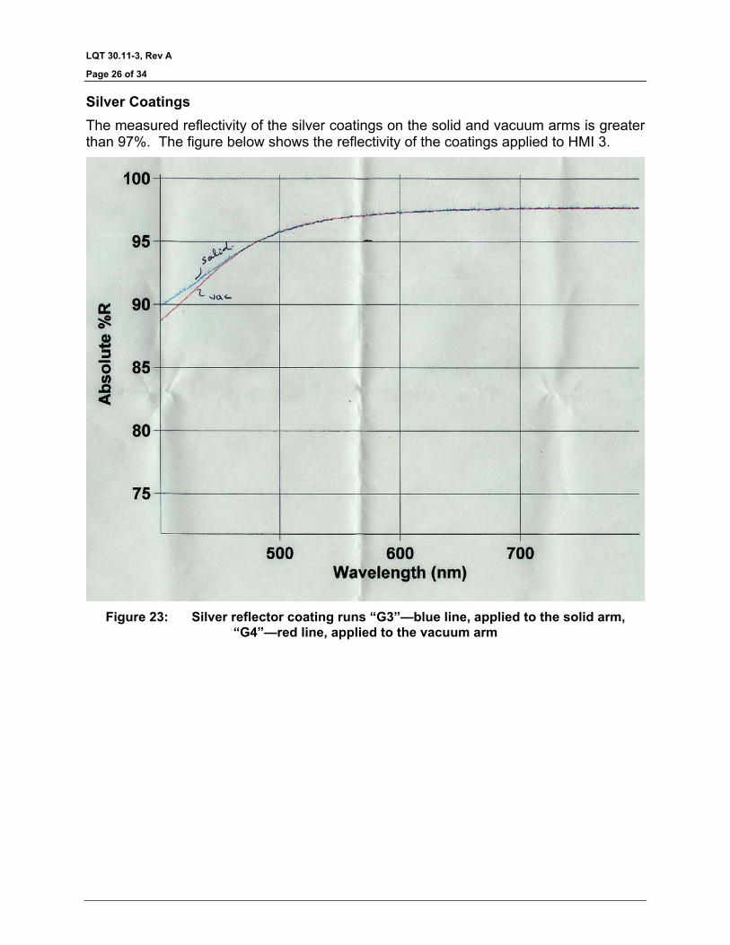
Silver Coatings The measured reflectivity of the silver coatings on the solid and vacuum arms is greater than 97%. The figure below shows the reflectivity of the coatings applied to HMI 3.
Figure 23: Silver reflector coating runs “G3”—blue line, applied to the solid arm,
“G4”—red line, applied to the vacuum arm

LQT 30.11-3, Rev A
Page 27 of 34
Surface quality (3.10) All of the optical surfaces of the interferometer are better than the specified 60-40 scratch dig specification.
Cement (3.11) The following table shows the type of cement used for each interface, and the lot code for the cement.
Interface Cement
Lot, expiry
BSL7Y—BSL7Y beam splitter Norland 61 233, 2005 Dec 4
BSL7Y—crystal quartz Norland 65 184, 2005 Sep 23
CaF2—BSL7Y (wave plate) Norland 65 185, 2005 Dec 6
BSL7Y—PVA polarizer Norland 65 Cemented by Lockheed Martin
BSL7Y polarizer—BSL7Y cube Norland 65 185, 2005 Dec 6
BSL7Y input/output wave plate—BSL7Y cube
Norland 65 185, 2005 Dec 6
BSL7Y wave plate—BSL7Y solid arm
Norland 65 188, 2006 Sep 28
BSL7Y solid arm—BSL7Y cube Norland 65 188 2006 Sep 28
CaF2—BSL7Y cube Norland 65 185, 2005 Dec 6
This table records the parallelism of the cemented components to the surfaces of the cube.
Measured parallelism between optic and cube Michelson face
fringes Wedge (arc seconds)
Polarizer 1.0 1.4
Input/output wave plate 0.5 0.7
Vacuum arm 0.5 0.7
Solid arm 0.5 0.7

LQT 30.11-3, Rev A
Page 28 of 34
Assembly dimensions and identification (3.12)
Overall Dimensions Dimension Measured value (measured
in inches, converted to mm) Specification limits
Measured with
X (wave plate to vacuum arm)
2.416” 61.37 mm
<64.0 mm
Y (polarizer to solid arm)
2.461” 62.50 mm <65.0 mm
Mitutoyo 3” micrometer 103-217, sn 3024721. Checked with 2.000” gauge block prior to measurements
Z (height) 1.775” 45.08 mm 45.0±0.1 mm Mitutoyo 2” micrometer 103-136, sn 1018456. Checked with 2.000” gauge block prior to measurements
Cube dimensions Dimension Measured value Measured with
X 45.09 mm
Y 45.06 mm
Z 45.08 mm
Mitutoyo 2” micrometer 103-136, sn 3007090. Checked with 2.000” gauge block prior to measurements
Wave Plates Location Serial
Number Thickness Maximum error
Input/Output #25 4.059 mm -λ/1400 λ/1900
Vacuum arm #27 8.052 mm -λ/680 λ/2800
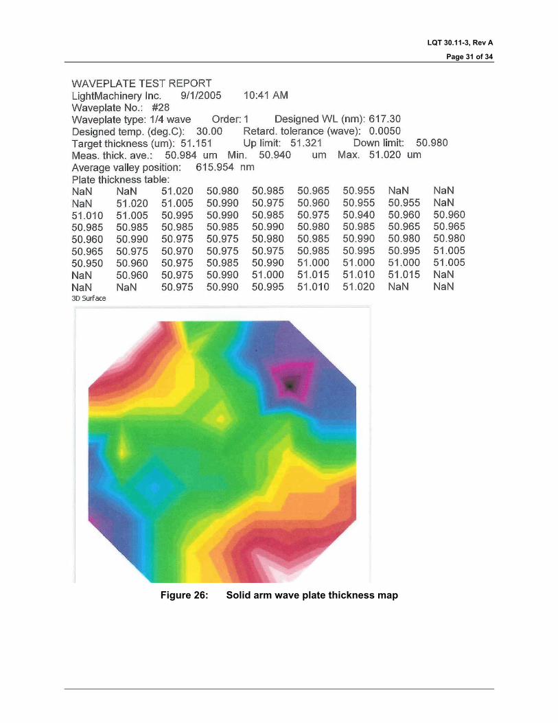
Solid arm #28 8.052 mm -λ/420 -λ/790
Note that the wave plate test set up had a small amount of systematic birefringence which was compensated by averaging the results of two measurements with the wave plate rotated 90° between measurements. The thickness plots that follow show the uniformity, but have not been corrected for this systematic error. The table above shows the corrected measurements. The maximum errors are the greatest deviations from the nominal three quarter wave retardation at 617.3nm on both the high side and the low side.

LQT 30.11-3, Rev A
Page 29 of 34
Wave Plate Thickness Measurements
Figure 24: Input/Output wave plate thickness map

LQT 30.11-3, Rev A
Page 30 of 34
Figure 25: Vacuum arm wave plate thickness map
LQT 30.11-3, Rev A
Page 31 of 34
Figure 26: Solid arm wave plate thickness map

LQT 30.11-3, Rev A
Page 32 of 34
Material Certificates, Process Certifications All of the glass used in the HMI Michelson is from the same melt of Ohara BSL7Y glass—material cerfificates attached. The wave plate sandwiches and solid arms were made from the 50 mm thick material, while the beam splitters were made from 35 mm thick material. The refractive index deltas are multiplied by 105 on the melt data sheets.
Figure 27: Material certificate for 35 mm thick Ohara BSL7Y glass
Figure 28: Material certificate for 50 mm thick Ohara BSL7Y glass
LQT 30.11-3, Rev A
Page 33 of 34
The crystal quartz used in this instrument was supplied by Sawyer Research. The material code is SP00356-000. The calcium fluoride spacers were fabricated from material supplied by Corning. The material was cut with the <111> crystal axis parallel to the optic axis of the instrument. The material code for the calcium fluoride is 702416. The PVA polarizer was assembled from BSL7Y blanks provided by LightMachinery, and PVA polarizer film provided by Lockheed Martin. Assembly of the polarizer sandwiches was performed by Lockheed Martin. AR coatings were applied to our specification CT-1835. Silver coatings were applied to our specification CT-1852. The polarizing beam splitter coating was applied by Iridian Spectral technologies; their run number #ds-bv-000009b000 bxft615b
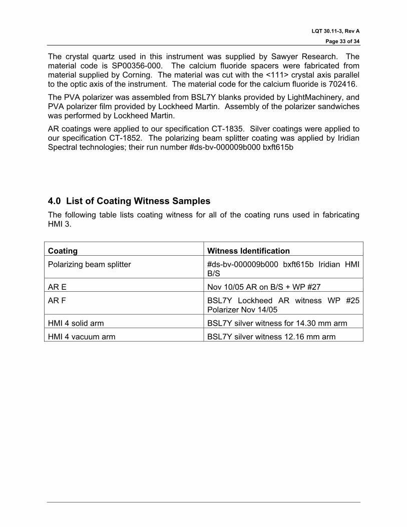
4.0 List of Coating Witness Samples The following table lists coating witness for all of the coating runs used in fabricating HMI 3.
Coating Witness Identification Polarizing beam splitter #ds-bv-000009b000 bxft615b Iridian HMI
B/S
AR E Nov 10/05 AR on B/S + WP #27
AR F BSL7Y Lockheed AR witness WP #25 Polarizer Nov 14/05
HMI 4 solid arm BSL7Y silver witness for 14.30 mm arm
HMI 4 vacuum arm BSL7Y silver witness 12.16 mm arm
LQT 30.11-3, Rev A
Page 34 of 34
This report was prepared by Ian Miller _________________________________, 2006 February 3 LightMachinery Inc. Director of R&D