lindab modular air handling units · selection software the aircalc++ selection software is an...
TRANSCRIPT

l indab | we simplify construction
Lindab Modular Air Handling Units Technical Catalogue

3
l indab | modular air handling units
Content Lindab Modular Air Handling Units
General characteristics ……………........................ 4
• Description ................................................................ 4
Types and application areas ……………................. 6
• Indoor air handling units ............................................. 6
• Outdoor air handling units .......................................... 6
• Swimming pool air handling units ................................ 7
• Hygienic air handling units .......................................... 8
• Explosion-proof air handling units .............................. 8
Examples of typical configurations ……………...... 9
Selection software ……………............................. 11
Sizes and dimensions ……………........................ 12
• Cross section dimensions ....................................... 12
• Size specification table ........................................... 12
Functional units …………….................................. 13
• Designations overview ............................................. 13
• Fan section ............................................................... 17
Plug fan with an EC motor ................................. 17
Plug fan with an AC motor ................................. 17
Direct-driven fan with a spiral housing ............... 17
• Heating section ......................................................... 18
Water heater ..................................................... 18
Frost protection ........................................... 19
Steam heater ..................................................... 19
Condenser ...................................................... 20
Electric heater ................................................... 20
Indirect gas heater ............................................. 21
• Humidification section ............................................... 22
Spray humidifier ................................................ 22
Steam humidifier ............................................... 23
Honeycomb humidifier ...................................... 23
High-pressure humidifier ................................... 26
• Cooling section ......................................................... 28
Water cooler ...................................................... 28
Water cooler with droplet eliminator ................... 28
Direct evaporator (DX cooler) ............................. 29
Siphon ............................................................... 30
• Compressor section ................................................. 30
• Filter section .............................................................. 31
Panel filter .......................................................... 31
Bag filter ........................................................... 31
Metal filter .......................................................... 32
Activated carbon filter ....................................... 33
High-efficiency filter .......................................... 33
• Sound attenuation section ....................................... 34
• Heat recovery section .............................................. 34
Run-around coil ................................................ 34
Cross-flow plate heat exchanger ..................... 36
Double plate cross-flow heat exchanger ........ 36
Counter-flow heat exchanger .......................... 37
Rotary heat exchanger .................................... 37
Heat pump ………………………...................... 38
Controls ………………………………................. 39

4
General characteristics
DescriptionModular air handling units are intended for central
preparation of air and offer all essential functions,
including heating, cooling, filtration, humidification,
dehumidification, heat recovery, and regeneration.
They feature outstanding flexibility due to the adjustable mo-
dular construction, availability of 43 standard sizes with air
volume flow rates ranging from 1.000 up to 100.000 m³/h,
and a customized selection of high-efficiency functional
elements.
Among the distinctive features is easy installation due to a
solid housing and adaptability to the building entrance
conditions, as well as simplicity of interconnection into a
set inside or outside the housing.
Air handling units can be dismantled into any number of
compact sets, depending on the number of functional
sections, unit size, transport options, and building require-
ments.
We can offer a package solution of an air handling unit with
an integrated cooling system and control systems. Air
handling units can be fitted with all the control equipment
required for automatic operation. We can also manage the
start-up of the unit and train the maintenance personnel for
proper unit handling.
Application• Indoor version (KNN)
• Outdoor version (KZN)
• AHU for swimming pools (KBN)
• Hygienic AHU (KHN)
• ATEX (KXN)
Quality & CertificatesHigh and constant quality of the manufacturing
process and products is our priority. Lindab air handling
units conform to the following standards and directives:
• ISO 9001:2015
• Eurovent certificate for the Klimair2 range. Tests of
mechanical characteristics and air flow rates were
performed according to EN 1886 and EN 13053.
• Hygienic air handling units conform to DIN 1946-4, EN
13053 and VDI 6022-1.
• ErP 2018 Directive – detailed info on requirements is
stated in a separate brochure.
• European directive for machinery, low voltage and
electromagnetic compatibility.
• Explosion-proof models are made in conformity with
the Directive 2014/34/EU, ATEX certificate.
Housing typesThe housing of Lindab air handling units features high
mechanical stability and low energy consumption, com-
bined with a low risk of housing condensation due to the
high quality of thermal insulation and air-tightness of the
housing. Acoustic and thermal insulation is made of 50
mm thick mineral wool, glued to the panels, with fibres
oriented perpendicular to the wall surface. It is non-flam-
mable and it remains stable over time. Internal surfaces
are flat and smooth.

5
l indab | modular air handling units
Within the Klimair2 housing family, two housing types
are available:
TopAir Plus
• An energy-efficient housing with improved thermal
bridges and a thermal transmittance class suitable for
demanding applications.
• Stainless steel AISI 304
• Peraluman
Several standard set-up and assembly options are avai-
lable to suit individual building characteristics:
• Horizontal air handling units [L]
• Two-stage air handling units [D]
• Parallel air handling units [V]
• Vertical air handling units [S]
• Combined air handling units [K]
Customized solutions are available on request.
Heat recovery systemsSelect an optimal recovery system:
• Run-around coil
• Cross-flow plate heat exchanger
• Double plate cross-flow heat exchanger
• Counter-flow heat exchanger
• Rotary heat exchanger
• Heat pump
Panels & doorsTop, bottom and side cover panels as well as doors are
made of 50 mm double walls, with the inner and outer
walls consisting of steel sheet and a mineral wool thermal
insulation filler with a density of 90 kg/m³.
As the mineral wool is glued to the panel, it also has a
supporting function, ensuring quality concerning not only
thermal and sound insulation but also stability. Thermal
break aluminium profiles effectively prevent unfavourable
thermal bridging on the housing.
Flammability classThe side, bottom and top walls, and the doors complies
with class A1 according to EN 13501-1, which stands for
non-combustible materials.
Filter leakageFilter leakage complies with class F9 according to EN
1886.
Thermal stabilityThe upper limit of the air handling unit thermal stability
range is +80 °C – on account of the components sensitive
TopAir
• The standard housing, fulfilling most project demands.
Housing characteristics
Klimair2/ TopAir Plus
Klimair2/ TopAir
Mechanical stability D1 D1
Leakage L1 L3
Thermal transmittance T2 T2
Thermal bridging TB2 TB3
Additional anticorrosion powder-coating or use of stainless
materials ensure extended service life. Any combination of
steel sheet materials is available, such as:
• Galvanized sheet steel
• Powder-coated sheet steel RAL 7035
• Aluzinc

6
to high temperatures, such as fan bearings, drive belts,
the filter medium, gaskets, etc. For temperatures exceed-
ing +40°C, enhanced insulation electric motors should be
installed.
Air handling unit types and application areas
Indoor air handling units - KNNThe indoor KNN air handling unit is the most frequently
used version. Pipes and other connections, as well as
control elements, are placed on the outer side of the unit’s
housing.
Outdoor air handling units – KZNThe KZN outdoor air handling unit is made of powder-
coated steel sheet; it has a protective roof, special protec-
tion hoods and grids at the supply air inlet and the exhaust
air outlet. Connections and control elements are installed
inside the unit.
Casing acoustical insulation
125 Hz 250 Hz 500 Hz 1000 Hz 2000 Hz 4000 Hz 8000 Hz
Klimair2/TopAir 12 10 10 16 25 33 43
Klimair2/TopAir plus 14 13 13 17 25 36 45
7
l indab | modular air handling units
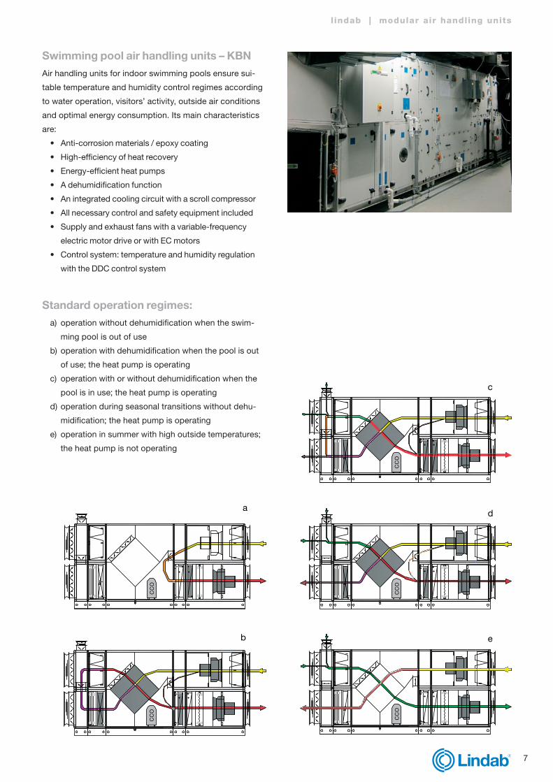
Swimming pool air handling units – KBNAir handling units for indoor swimming pools ensure sui-
table temperature and humidity control regimes according
to water operation, visitors’ activity, outside air conditions
and optimal energy consumption. Its main characteristics
are:
• Anti-corrosion materials / epoxy coating
• High-efficiency of heat recovery
• Energy-efficient heat pumps
• A dehumidification function
• An integrated cooling circuit with a scroll compressor
• All necessary control and safety equipment included
• Supply and exhaust fans with a variable-frequency
electric motor drive or with EC motors
• Control system: temperature and humidity regulation
with the DDC control system
Standard operation regimes:a) operation without dehumidification when the swim-
ming pool is out of use
b) operation with dehumidification when the pool is out
of use; the heat pump is operating
c) operation with or without dehumidification when the
pool is in use; the heat pump is operating
d) operation during seasonal transitions without dehu-
midification; the heat pump is operating
e) operation in summer with high outside temperatures;
the heat pump is not operating
a
b
c
d
e
CC
OC
CO
CC
OC
CO
CC
O
a
b
c
d
e
CC
OC
CO
CC
OC
CO
CC
O
a
b
c
d
e
CC
OC
CO
CC
OC
CO
CC
O
a
b
c
d
e
CC
OC
CO
CC
OC
CO
CC
O
a
b
c
d
e
CC
OC
CO
CC
OC
CO
CC
O

8
Hygienic air handling units – KHNHygienic air handling units (KHN) are used in hospitals, in
the food and pharmaceutical industries, and in other clean
room applications. Main features:
• Construction without grooves and sharp edges.
• All functional elements (fans, coils, heat recovery units,
humidifiers …) are easily removable for maintenance,
cleaning, and service.
• All elements are resistant to corrosion.
• All components and materials are resistant to disinfec-
tants.
• Seals are smooth, abrasion-resistant, closed-pore.
• Build-in components are tested and recognised as
effective per the list of the Robert Koch Institute (RKI) or
the disinfectant media list of the Association for Applied
Hygiene (VAH).
• The internal panels of the housing are made of painted
sheet steel, while the bottom is made of stainless sheet
steel AISI 304. On special request, the internal panels
are available in stainless sheet steel AISI 316.
• All external panels are made of galvanised sheet steel,
while all the joints between the frame and the panels are
sealed with a clean room application putty.
• Filter classes acc. to ISO 16890
• ISO ePM10 >50%: pollen
• ISO ePM2.5>50%: bacteria, fungal, mold spores
• ISO ePM1>50%: viruses, nanoparticles, exhaust
gases
• High-efficiency filters (acc. to EN1822): E11, E12,
H13, H14
• The units feature plug-in high-efficiency fans, epoxy
coated coil frame and fins, a highly efficient run-around
coil system and dampers for increased tightness
requirements (class 4 according to EN 1751).
• Sound attenuators are made of abrasion-resistant and
waterproof material.
Explosion-proof air handling unitsExplosion-proof air handling units correspond to the
following categories:
• Equipment group II
• Equipment category 2 and 3
• Explosive atmosphere, caused by gases and vapours (G)
• Temperature classes T1, T2, T3, T4
(ignition temperature T>+135 °C)
• Protection based on the ATEX Directive 2014/34/EU
Example of designation:
II 2 G IIB - T4
9
l indab | modular air handling units
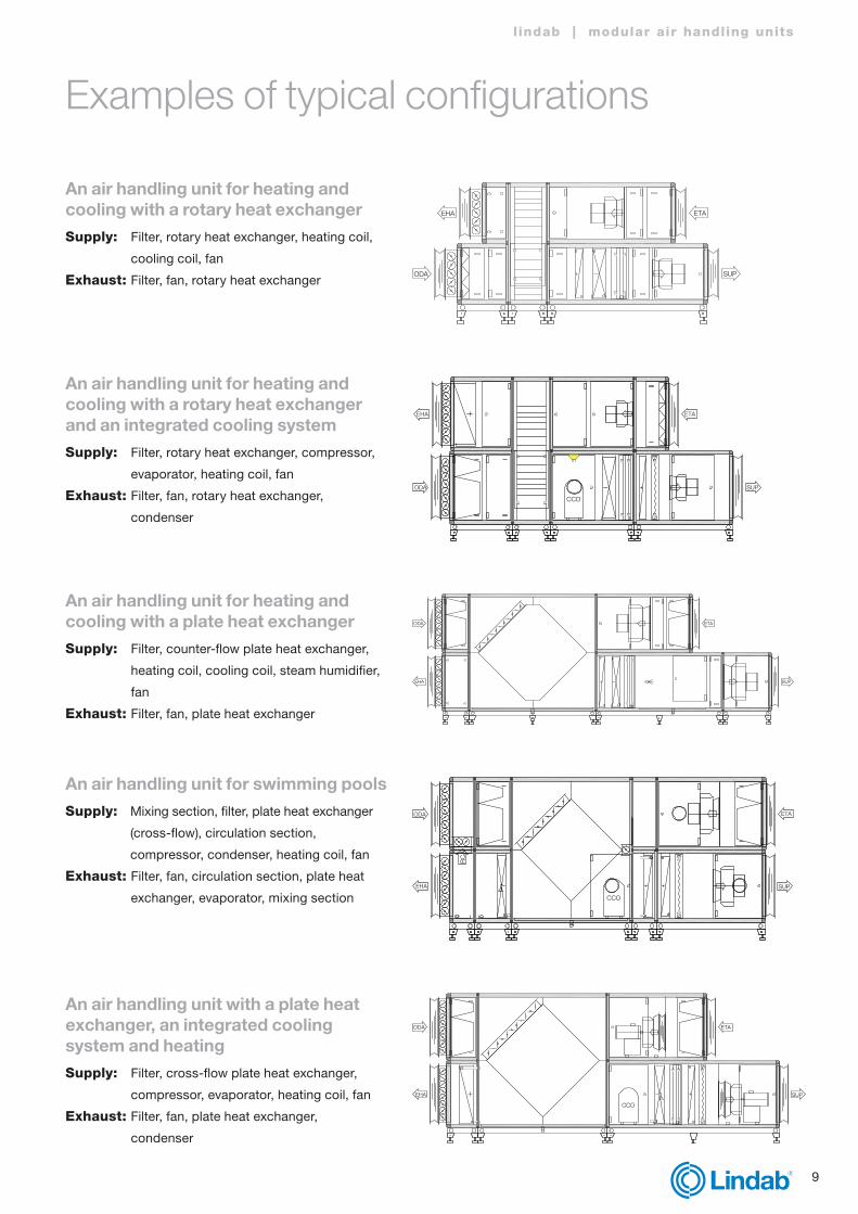
Examples of typical configurations
An air handling unit for heating and cooling with a rotary heat exchangerSupply: Filter, rotary heat exchanger, heating coil,
cooling coil, fan
Exhaust: Filter, fan, rotary heat exchangerODA
EHA ETA
SUP
ODA
EHA
CCO
ETA
SUP
EHA
ODA ETA
SUP
EHA
RCA
ODA
CCO
SUP
ETA
EHA
ODA
CCO
ETA
SUP
An air handling unit for heating and cooling with a rotary heat exchanger and an integrated cooling systemSupply: Filter, rotary heat exchanger, compressor,
evaporator, heating coil, fan
Exhaust: Filter, fan, rotary heat exchanger,
condenser
An air handling unit for heating and cooling with a plate heat exchanger Supply: Filter, counter-flow plate heat exchanger,
heating coil, cooling coil, steam humidifier,
fan
Exhaust: Filter, fan, plate heat exchanger
An air handling unit for swimming poolsSupply: Mixing section, filter, plate heat exchanger
(cross-flow), circulation section,
compressor, condenser, heating coil, fan
Exhaust: Filter, fan, circulation section, plate heat
exchanger, evaporator, mixing section
An air handling unit with a plate heat exchanger, an integrated cooling system and heatingSupply: Filter, cross-flow plate heat exchanger,
compressor, evaporator, heating coil, fan
Exhaust: Filter, fan, plate heat exchanger,
condenser

10
An air handling unit for heating and cooling with a run-around coilSupply: Filter, run-around glycol heater, heating
coil, cooling coil, fan
Exhaust: Filter, fan, run-around glycol cooler
ODA SUP
EHA ETA
ETA
SUP
CCO
RCA
EHA
ODA
An air handling unit with adiabatic cooling and a double plate heat exchangerSupply: Filter, circulation section, fan,
double-plate heat exchanger,
compressor, evaporator, heating
coil, filter
Exhaust: Filter, adiabatic cooling,
double-plate heat exchanger,
condenser, circulation section,
fan
11
l indab | modular air handling units
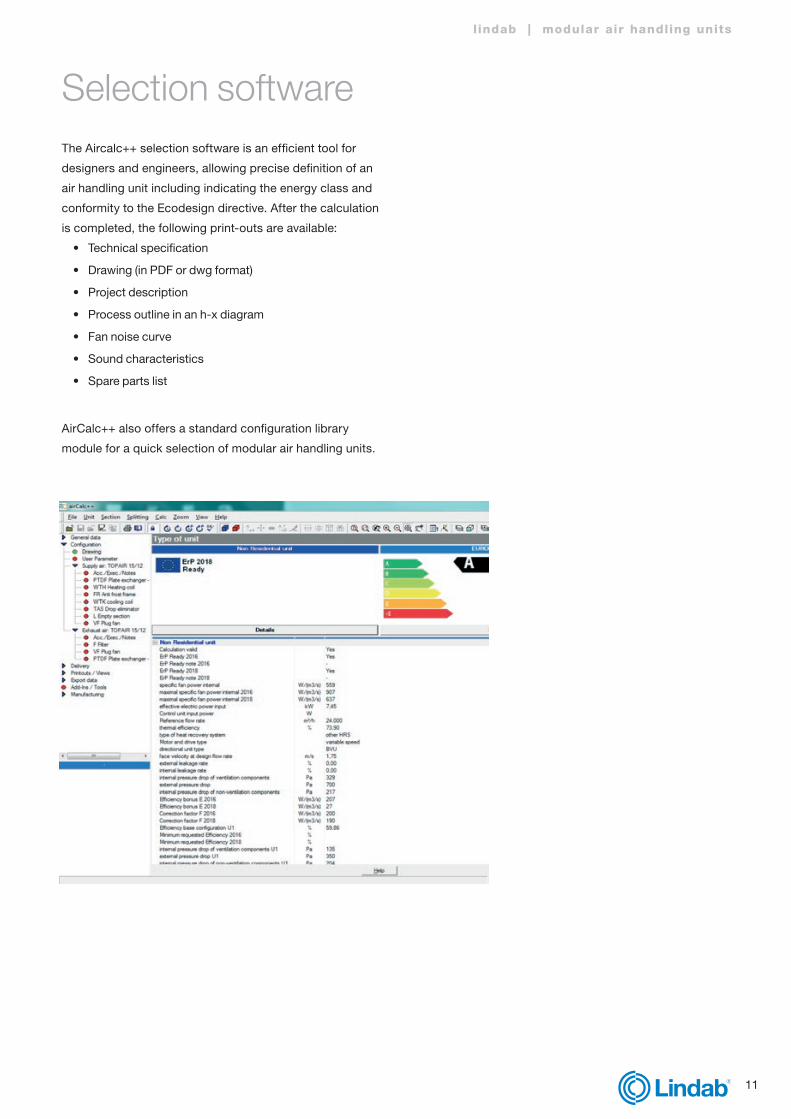
Selection softwareThe Aircalc++ selection software is an efficient tool for
designers and engineers, allowing precise definition of an
air handling unit including indicating the energy class and
conformity to the Ecodesign directive. After the calculation
is completed, the following print-outs are available:
• Technical specification
• Drawing (in PDF or dwg format)
• Project description
• Process outline in an h-x diagram
• Fan noise curve
• Sound characteristics
• Spare parts list
AirCalc++ also offers a standard configuration library
module for a quick selection of modular air handling units.
12
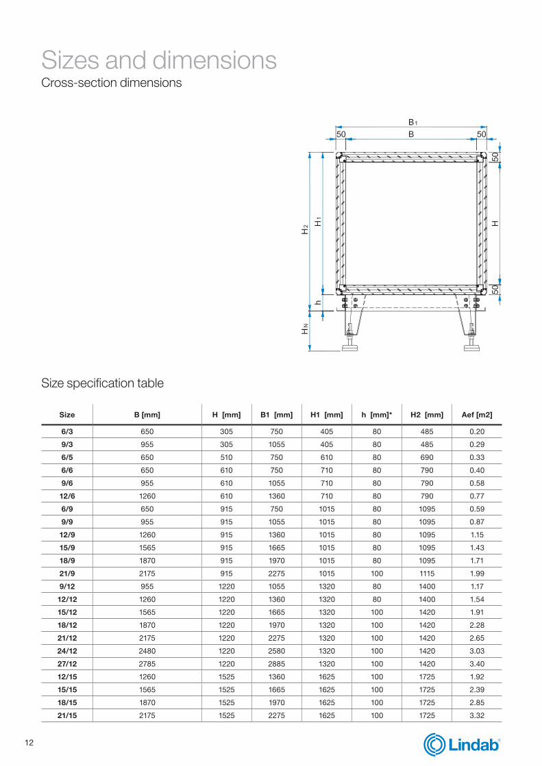
Sizes and dimensions Cross-section dimensions
Size B [mm] H [mm] B1 [mm] H1 [mm] h [mm]* H2 [mm] Aef [m2]
6/3 650 305 750 405 80 485 0.20
9/3 955 305 1055 405 80 485 0.29
6/5 650 510 750 610 80 690 0.33
6/6 650 610 750 710 80 790 0.40
9/6 955 610 1055 710 80 790 0.58
12/6 1260 610 1360 710 80 790 0.77
6/9 650 915 750 1015 80 1095 0.59
9/9 955 915 1055 1015 80 1095 0.87
12/9 1260 915 1360 1015 80 1095 1.15
15/9 1565 915 1665 1015 80 1095 1.43
18/9 1870 915 1970 1015 80 1095 1.71
21/9 2175 915 2275 1015 100 1115 1.99
9/12 955 1220 1055 1320 80 1400 1.17
12/12 1260 1220 1360 1320 80 1400 1.54
15/12 1565 1220 1665 1320 100 1420 1.91
18/12 1870 1220 1970 1320 100 1420 2.28
21/12 2175 1220 2275 1320 100 1420 2.65
24/12 2480 1220 2580 1320 100 1420 3.03
27/12 2785 1220 2885 1320 100 1420 3.40
12/15 1260 1525 1360 1625 100 1725 1.92
15/15 1565 1525 1665 1625 100 1725 2.39
18/15 1870 1525 1970 1625 100 1725 2.85
21/15 2175 1525 2275 1625 100 1725 3.32
Size specification table
13
l indab | modular air handling units
Functional units Designations overview
* Note: possibility to choose h=200mm
24/15 2480 1525 2580 1625 100 1725 3.78
30/15 3090 1525 3190 1625 100 1725 4.71
15/18 1565 1830 1665 1930 100 2030 2.86
18/18 1870 1830 1970 1930 100 2030 3.42
21/18 2175 1830 2275 1930 100 2030 3.98
24/18 2480 1830 2580 1930 100 2030 4.54
27/18 2785 1830 2885 1930 100 2030 5.10
18/21 1870 2135 1970 2235 100 2335 3.99
21/21 2175 2135 2275 2235 100 2335 4.64
24/21 2480 2135 2580 2235 100 2335 5.29
27/21 2785 2135 2885 2235 100 2335 5.95
30/21 3090 2135 3190 2235 100 2335 6.60
21/24 2175 2440 2275 2540 100 2640 5.31
24/24 2480 2440 2580 2540 100 2640 6.05
27/24 2785 2440 2885 2540 100 2640 6.80
30/24 3090 2440 3190 2540 100 2640 7.54
36/24 3395 2440 3495 2540 100 2640 8.28
24/27 2480 2745 2580 2845 100 2945 6.81
27/27 2785 2745 2885 2845 100 2945 7.64
30/27 3090 2745 3190 2845 100 2945 8.48
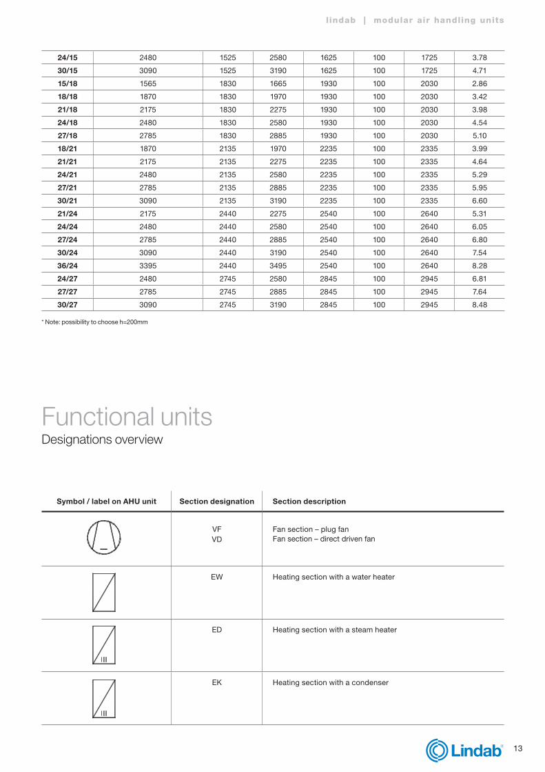
Symbol / label on AHU unit Section designation Section description
VFVD
Fan section – plug fan Fan section – direct driven fan
EW Heating section with a water heater
ED Heating section with a steam heater
EK Heating section with a condenser

14
EE Heating section with an electric heater
EGI Heating section with an indirect gas heater
FR Anti-freezing protection section
BLW Humidification section with a spray humidifier
Humidification section with a high-pressure humidifier
BD Humidification section with a steam humidifier with an electric steam generator
BD Humidification section with a steam humidifier with an outside steam section
BWA Humidification section with a contact humidifier
KW Cooling section with a water cooler
KD Cooling section with a direct evaporator (DX)
KW-TA Cooling section with a water cooler – with a droplet eliminator
KD-TA Cooling section with a direct evaporator – with a droplet elimi-nator
TA Droplet eliminator
KO Compressor section

15
l indab | modular air handling units
A Intake section – with a single control damper
M Mixing section – with two control dampers
MD Dual mixing section – with three control dampers
U Circulation section
FKFT
FTTFM
Panel filter sectionBag filter sectionBag filter section – model with doorMetal grease filter section
FAK Activated carbon filter section
FA High-efficiency filter section
S Sound attenuation section
LU Empty angle section
RKE RKK
RKK-TA
Recuperation section with a run-around coilHeating partCooling partCooling part with a droplet eliminator
RPD Recuperation section with a cross-flow plate heat exchanger (diagonal design)
RPDC Recuperation section with a counter-flow plate heat exchanger
RPDB Recuperation section with a double plate cross-flow heat exchanger
RRG Recuperation section with a rotary heat exchanger

16
RWR Recuperation section with a heat pipe
D Diffuser section
J Control damper
ST Flexible connection
H Protection hood
WSG Protection grille
EEJ Control damper electric heater
HHH H
10
Section total pressure [Pa]
H [mm] - Positive/negative pressure
300 40
600 75
900 110
1200 140
1500 175
1800 210
2100 240
Negative pressure siphon - side connection:
Electric controlcabinet section
Air directionmedium direction
Medium entryred colour
Medium entryblue colour
Handleposition open
Controldamper open
Medium exitblue colour
Medium exitred colour
Handle positionclosed
Controldamper closed
Positive pressure siphon - side connection:
Negative pressure siphon - bottom connection:
Positive pressure siphon - bottom connection:
17
l indab | modular air handling units
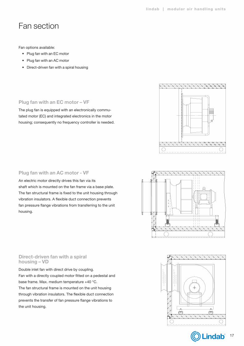
Fan section
Fan options available:
• Plug fan with an EC motor
• Plug fan with an AC motor
• Direct-driven fan with a spiral housing
Plug fan with an EC motor – VFThe plug fan is equipped with an electronically commu-
tated motor (EC) and integrated electronics in the motor
housing; consequently no frequency controller is needed.
Plug fan with an AC motor - VFAn electric motor directly drives this fan via its
shaft which is mounted on the fan frame via a base plate.
The fan structural frame is fixed to the unit housing through
vibration insulators. A flexible duct connection prevents
fan pressure flange vibrations from transferring to the unit
housing.
Direct-driven fan with a spiral housing – VDDouble inlet fan with direct drive by coupling.
Fan with a directly coupled motor fitted on a pedestal and
base frame. Max. medium temperature +40 °C.
The fan structural frame is mounted on the unit housing
through vibration insulators. The flexible duct connection
prevents the transfer of fan pressure flange vibrations to
the unit housing.
18
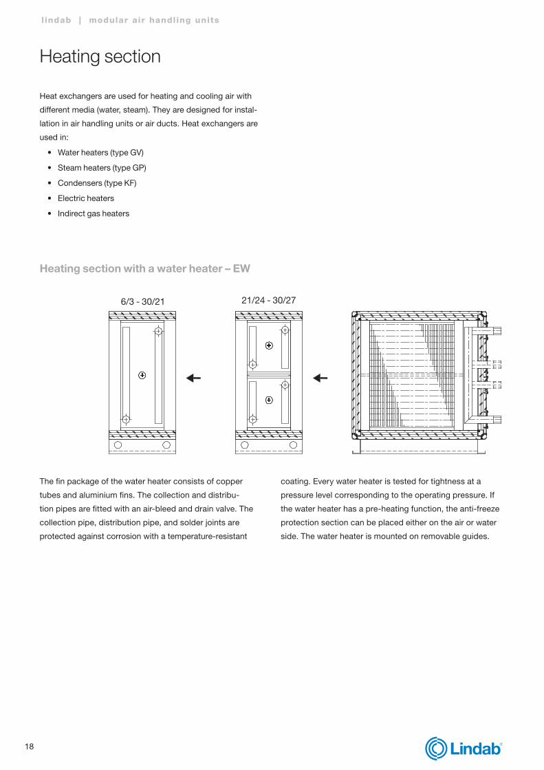
Heating section
Heat exchangers are used for heating and cooling air with
different media (water, steam). They are designed for instal-
lation in air handling units or air ducts. Heat exchangers are
used in:
• Water heaters (type GV)
• Steam heaters (type GP)
• Condensers (type KF)
• Electric heaters
• Indirect gas heaters
l indab | modular air handling units
Heating section with a water heater – EW
6/3 - 30/21 21/24 - 30/27
coating. Every water heater is tested for tightness at a
pressure level corresponding to the operating pressure. If
the water heater has a pre-heating function, the anti-freeze
protection section can be placed either on the air or water
side. The water heater is mounted on removable guides.
The fin package of the water heater consists of copper
tubes and aluminium fins. The collection and distribu-
tion pipes are fitted with an air-bleed and drain valve. The
collection pipe, distribution pipe, and solder joints are
protected against corrosion with a temperature-resistant

19
l indab | modular air handling units
Section with frost protection: FRThe frost protection can be installed on the water side or
the air side. If controls are supplied by Lindab, the frost
protection regulation is already provided. In other cases,
only a frame for the installation of a capillary tube is pre-
pared for the air side option. For the water side option, a
connection for the temperature sensor is mounted in the
heat exchanger at the factory.
The steam heater consists of a frame and an aluminium fin
package with copper pipes, collection pipes and distribu-
tion pipes. Aluminium fins and copper pipes are joined
through mechanical expansion.
The collection and distribution pipes, which interconnect
the copper pipes, are made of steel and are fitted with a
thread or flange connection and an air-bleed and drain
valve.
The steam heater frame protects pipe elbows and is used
Heating section with a steam heater: ED
to mount the heater in the unit. The water heater is fitted
into the housing through guides allowing easier removal.
The collection pipe, distribution pipe, and solder joints are
protected against corrosion with a temperature resistant
coating.
Steam heater (GP type): working medium steam, utilizing
only saturated steam condensation heat. Serviceable up to
9 bar maximum.
The steam heater is mounted on removable guides.

20
A heating section with a condenser is a part of the inte-
grated cooling system.
The condenser heats the air through a Freon-based agent
R410a and R407c. If required, a condenser can be divided
into two or more cooling circuits.
The condenser is mounted in the housing using guides
allowing its removal in case of defect or damage.
Heating section with a condenser: EK
Heating section with an electric heater: EEAn electric heater section consists of the section housing, an
electric air heater, and a two-stage protection thermostat.
The electric heater is mounted in the housing using guides
allowing its removal in case of defect or damage.
Selection guidelines: EE
• Airflow velocity through the electric air heater should
not be less than 1.5 m/s.
• Functional sections with temperature-sensitive
components should be separated from the electric
heater section with an empty section no less than 650
mm long.
• If the electric air heater section is installed downstream
of the fan section (the fan blowing into the heater), there
should be an empty section, (with a length of
L = (H+B)/2
H = air handling unit height,
B = width – but in no case less than 600 mm) installed
between the two.

21
l indab | modular air handling units
Heating section with an indirect gas heater: EGI
1. Combustion chamber2. Gas train3. Flue pipe4. Gas burner with continuous (stepless) control of the
heating power5. Top-to-heater and bottom-to-heater air-directing baffle
An indirect gas heater section consists of the section hou-
sing and an indirect gas heater.
The basic indirect gas heater section outline, applicable to
all indirect gas heater types, is shown in the figure below.
The indirect gas heater consists of a heat exchanger, a
pressure gas burner, a burner (gas) train, and monitoring
and safety equipment.
The stainless steel sheet heat exchanger consists of a
combustion chamber, a coil set and a collection chamber
with a flue gas pipe. A flue gas condensate collection and
drain pan is fitted below the heat exchanger.
The gas burner is flange-mounted to the combustion
chamber opening from the outer (access) side of the sec-
tion housing, while the flue pipe is routed through the sec-
tion housing back wall. The declared minimum surrounding
temperature for the normal operation of the gas is -15 °C.
6. Condensate drain7. Safety thermostat – set to 80 °C – and security
temperature sensor – set to 90 °C7.1. Safety thermostats and security temperature sensor8. Differential pressure switch – with a range of up to 500 Pa8.1. Pressure-measuring tube

22
Humidification section
The humidification section offers the ability to increase the
humidity of the inlet air to a suitable temperature.
Types of humidification units:
• Humidification section with a spray humidifier
Humidification section with a spray humidifier: BLWA spray humidifier section consists of a single-wall hou-
sing, a pool made of steel sheet 1.4301 and other com-
ponents. The pool bottom surface is inclined towards the
drain connection, which is located at the lowest point of
the bottom.
The airflow-directing element and droplet eliminator con-
sist of polypropylene fins (blades). For cleaning, they can
be removed from the section housing.
The PVC pipe system consists of a pressure line, internal
distribution piping, water spray nozzles, rinse and drain
pipes, and a water supply pipe.
The inspection door is fitted with a window to allow
inspection during operation.
The humidification section lighting is fitted on the outer
side of the front panel.
A level switch prevents dry operation.
Option: the flanged pump can be made entirely of stainless
steel.
1
B A
2 3 6
C
D
9 10
8
17 16
19
18 20 21
7 12 11 14 13 15
4,5
• Humidification section with a steam humidifier
• Humidification section with a honeycomb humidifier
• High-pressure humidifier
1. Manometer in the pressure line2. Stop valve before the manometer3. Droplet eliminator4. Electric switch5. Power distribution box6. Light7. Manual 2-way valve for rinsing8. 2-way valve in the pressure line9. Door with an inspection window10. Airflow directing rectifier11. Quick water fill valve12. Level switch – minimum water level maintenance13. Overflow pipe with a trap for Δp ≤ 1000 pa14. Intake strainer15. Drain pipe16. Housing17. Pressure nozzle18. Container19. Pressure distribution piping20. Ballcock – maximum water level maintenance21. Pump
A Dry air intakeB Humidified air outletC Fresh water supply connectionD Container water drain connection
Water treatment
Higher salt concentrations in spray water, caused by water
evaporation (air humidification), increase the risk of exces-
sive precipitation in the water part of the humidification
section and in the pipes.
A few water treatment (softening) methods:
• Polyphosphate addition
• Ion exchange

23
l indab | modular air handling units
• Decarbonisation
• Rinsing
• Occasional limescale removal
The water-spraying process in the humidifier has an
additional air-cleansing function; which means that dust
particles also collect in the water container.
The quantity of the rinsing water should be similar to that
of the supply water for humidification, and can be deter-
mined with the following equation:
Humidification section with a steam humidifier: BD
The steam humidifier section consists of a section hou-
sing, a steam humidifier, a condensate collection and drain
pan, a positive or negative pressure condensate drain
siphon, an access door with an inspection window, and
internal lighting.
The steam humidifier consists of a steam distributor, which
can be connected directly to the negative pressure steam
system through a valve, or to its own steam generator. The
steam distributor connection to the generator or the nega-
tive pressure steam system is established on the outer side
of the housing back wall.
The steam distributor is selected according to the humidi-
fication requirements and air handling unit size. Its installa-
tion according to the manufacturer’s instructions ensures
a relative air humidity rate at the end of the humidification
section below 90%.
Quantity of rinsing water:
QVS = VZ ∙ (x2 – x1)
QVS amount of water used for humidification (kg/h),
VZ amount of air humidified (kg/h),
(x2 – x1) change in the absolute humidity of air due to
humidification (g/kg).
Humidification section with a honeycomb humidifier: BWAThe honeycomb humidifier section consists of a section
housing, a honeycomb humidifier, and a negative or posi-
tive pressure condensate drain siphon. It is also fitted with
a double-wall inspection window, and internal lighting.
Two honeycomb humidifier models are available:
• Honeycomb humidifier with circulating water
• Honeycomb humidifier with direct water
Humidification efficiency at 2 m/s airflow velocity:
• 65% (cartridge thickness 100 mm)
• 85% (cartridge thickness 200 mm)
• 95% (cartridge thickness 300 mm)
A droplet eliminator is required for every section where
airflow velocity exceeds 3.5 m/s.
A solenoid valve allows water supply control for each car-
tridge independently (max. 5 cartridges).
Multi-step control is available with both the circulating and
direct water honeycomb humidifier model.

24
Water consumptionWater circulation system:
Total water consumption equals the sum of absorbed (E)
and rinsed (O) water.
Flushing the humidification section water tank is neces-
sary to maintain an appropriate level of mineral and salt
concentration in the water.
14
15
61110
2
1
3
79
85
12
4
13
C
A
D
B
Honeycomb humidifier with circulating water
92
1
3
654
4
8
10
C
A
D
B
Honeycomb humidifier with direct water
A Intake airB Humidified airC Water supplyD Waste water drain
1. Humidification cartridge2. Water distribution head3. Water distribution pipes4. Float5. Float-connected valve6. Valve for tank rinsing7. Rinse pipe8. Water distributor9. Flush control valve10. Pump11. Overflow pipe12. Tank drain and rinse pipe13. Negative pressure drain trap14. Droplet eliminator15. Inspection window
A Supply airB Humidified airC Water supplyD Exhaust water drain
1. Humidification cartridge2. Water distribution head3. Water distribution pipes4. Water distributor5. Negative pressure drain trap siphon6. Water distributor7. Tank drain and flush pipe8. Constant water flow rate control valve9. Droplet eliminator10. Inspection window
1.0 10 102 103 104
2.5 25 250 2500
CaCO3 mg/l
CaC
O3 m
g/l
2+
HCO3 mg/l
pH
Ca2+ mg/l
Direct water
(not circulating)
Non-Usable water
25000
f O fa
ctor 2,01,00,50,25
0,1
0,01
0,01
1,0
10
10
1,0
102104
6 7 8 9
103
102
Rinse factor:
With established water quality, the rinse factor (fo) can be
determined from the water quality diagram (see below).
If the rinse factor (fo value) is more than 2, we recommend
using a direct water system or improving the water quality.

25
l indab | modular air handling units
Installation
At the humidified air outlet, a 300–600 mm wide space
should be provided. Upon installation, all fissures towards
the housing must be sealed.
It is required that the air be filtered with ISO coarse filters
before entering into the humidifier. If it contains organic
particles, finer filters can be required.
We recommend the use of class ePM2.5 >50% filters
according to ISO 16890 for easier maintenance and better
quality.
Water supply with a circulating water humidifier:
Water supply connection:
• Stop valve*
• 500 μm water filter (if water contains coarse particles)*
The microbiological parameters of the supplied water must
correspond to drinking water quality standards and regula-
tions in force.
Water supply with direct water humidifier:
Water supply connection:
• Stop valve*
• 500 μm water filter (if water contains coarse particles)*
• Solenoid valve
• Constant flow rate control valve
The microbiological parameters of the supplied water must
correspond to drinking water quality standards and regula-
tions in force.
Total water consumption:
E = (V x 60 x 1,2 x (X2 – X1)) / 1000
O = fO x E
S = E + O
E Absorbed water quantity (l/min)
O Rinsed water quantity (l/min)
S Total water consumption (l/min)
V Volume air flow rate (m³/h)
1,2 Standard air density (kg/m³)
X2 Intake air humidity (g/kg)
X1 Outlet air humidity (g/kg)
fO Rinse factor
60 Conversion from (m³/s) to (m³/min)
1000 Conversion from (g/min) to (l/min)
Calculation example:
V = 2,8 m³/s
pH = 7,1
Calcium concentration
(Ca2+) = 100 mg/l (100 ppm)
Bicarbonate concentration
(HCO3) = 100 mg/l (100 ppm)
Intake air humidity (x1) = 2 g/kg
Outlet air humidity (x2) = 9 g/kg
From water quality diagram (fO) = 0,3
E = (2,8 x 60 x 1,2 x (9 – 2)) / 1000 =
E = 1,41 l/min
O = 0,3 x 1,41 = 0,42 l/min
S = 1,41 + 0,42 = 1,83 l/min
Water outlet:
Due to the negative pressure in the humidification section,
an adequate negative pressure trap is necessary to allow
rinsing.
Control:
Applicable to circulating and direct water humidifiers:
• One-step control*
• Two-step control*
• 3-, 4- or max. 5-step control available upon request*
• An external solenoid valve is not supplied with the humidifier
With multi-step control, the section has one internal sole-
noid valve less than the number of regulation steps.
* not part of humidifier standard equipment

26
Technical specifications
Pump motor protection: IP 54, EN 60034Pump motor insulation: class F
Supply water requirements
Circulating water Direct water
Minimum pressure 500 kPa 150 kPa
Maximum pressure 1000 kPa 1000 kPa
Temperature 0 °C – 40 °C 0 °C – 40 °C
Electromagnetic valve
Voltage (V)
Frequency (Hz)
Power (W)
Current (A)
230 50 – 60 6 – 12 0,10 – 0,21
Pump motor
Pump size* Voltage (V)±10 %
Frequency (Hz)
Power (W)
Current (A)
1 230/400 50 50 0,26/0,15
2 230/400 50 125 0,38/0,22
3 230/400 50 170 0,75/0,43
4 230/400 50 270 1,10/0,63
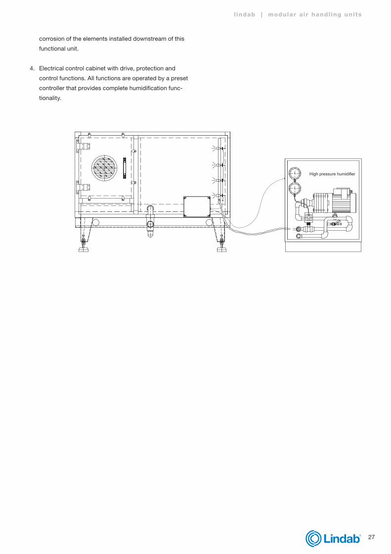
High-pressure humidifierA high-pressure humidifier is used for adiabatic humidifica-
tion of inlet air; therefore a spray-nozzle system is installed
in the inlet section of the air handling unit.
Main characteristics:
• The system is hygienic and harmless to health, certified
according to VDI 6022 and appropriate for hospital use.
• All components are made of stainless steel or plastics
and are corrosion resistant.
Main components:
1. A high-pressure pump aggregate featuring a pump
motor with an adjustable number of revolutions con-
trolled by a frequency controller and pressure sensor.
The aggregate uses water prepared to correspond to
different quality levels. The maximum allowed water
hardness is 4 odH (German grades). It can use sof-
tened or demineralised water.
Protection elements on the pump:
• Pressure switch
• Temperature controller
• Pressure valve
2. A nozzle system, consisting of:
• Pressure nozzles
• A stainless steel pipe system
• High-pressure flexible hoses to connect the pump
aggregate and the nozzle system, with corresponding
fittings.
3. A drop eliminator, installed at the end of the functional
unit, to eliminate aerosols from the airflow. It prevents
27
l indab | modular air handling units
corrosion of the elements installed downstream of this
functional unit.
4. Electrical control cabinet with drive, protection and
control functions. All functions are operated by a preset
controller that provides complete humidification func-
tionality.
28
Cooling section
The cooling section cools the inlet air in the summer. It is
designed based on the inlet parameters and flow rate.
Types of cooling units:
• Cooling section with a water cooler
• Cooling section with a water cooler with droplet eliminator
• Cooling section with direct expansion (DX)
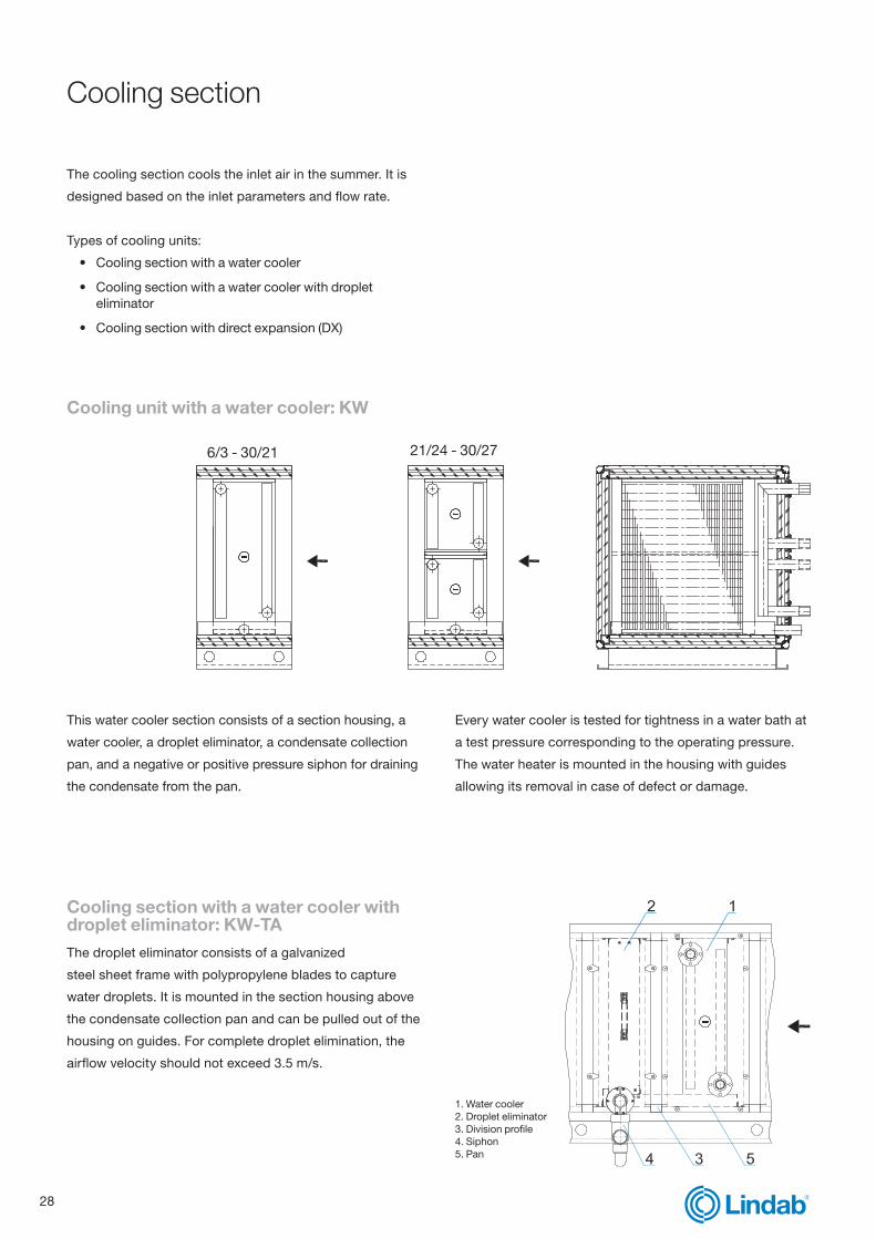
Cooling unit with a water cooler: KW
This water cooler section consists of a section housing, a
water cooler, a droplet eliminator, a condensate collection
pan, and a negative or positive pressure siphon for draining
the condensate from the pan.
Every water cooler is tested for tightness in a water bath at
a test pressure corresponding to the operating pressure.
The water heater is mounted in the housing with guides
allowing its removal in case of defect or damage.
Cooling section with a water cooler with droplet eliminator: KW-TAThe droplet eliminator consists of a galvanized
steel sheet frame with polypropylene blades to capture
water droplets. It is mounted in the section housing above
the condensate collection pan and can be pulled out of the
housing on guides. For complete droplet elimination, the
airflow velocity should not exceed 3.5 m/s.
1. Water cooler2. Droplet eliminator3. Division profile4. Siphon5. Pan
6/3 - 30/21 21/24 - 30/27

29
l indab | modular air handling units
Horizontal design
Vertical design
6/3 - 30/21 21/24 - 30/27
Cooling section with direct expansion (DX): KD
A cooling section with direct expansion with a
droplet eliminator: KT-DA
The DX cooler cools the air using Freon-based cooling
agents (R410a and R407c). If required, a DX cooler can be
divided into two or more cooling circuits.
A direct evaporator is mounted in the housing with guides
allowing its removal in case of defect or damage.

30
Compressor section: KO
Negative pressure siphon with a ball
Positive pressure siphon
SiphonA siphon is a plastic pipe which enables condensate to
drain in case of negative pressure in the air handling unit
or an individual section, and prevents air leakage through
the drain pipe in case of positive pressure in the unit or an
individual section.
For siphon dimensioning, see separate Installation Manual.
The compressor section consists of a section housing, one
or more compressors and their respective cooling circuit
components, a condensate collection pan, and a negative
or positive pressure siphon.
It may be designed as an independent section or as part of
another section, such as a mixing section, plate recuperator
section, etc.
This section always contains an access door with an
inspection window and an internal light as an option.

31
l indab | modular air handling units
Filter section
The filter section maintains the quality of the inlet air.
Based on the desired air quality and level of filtration,
different filters are installed: panel, bag, metal, high-effi-
ciency, or activated carbon filter sections.)
Panel filter section: FKA panel filter consists of a galvanized sheet steel frame
with a width of 100 mm and an inserted zigzag filter
medium made of synthetic fibres. Filter mediums are
resistant to temperatures up to 70 °C, with the exact tem-
perature range stated by manufacturers.
For the initial and recommended final pressure drop
values, see the technical data sheet generated in the
selection software for each air handling unit.
Bag filter section: FT (filter access from the dirty side)The filter medium is clamped to the bag filter frame using
spring clamps.
Bag filters are delivered in two lengths (360 or 600 mm)
and can be made of two different types of material: fibre-
glass or synthetic fibres, with temperature ratings up to ≈
70°C. The manufacturers determine the exact temperature
resistance range.
1. Panel filter2. Guide3. Mechanical lock4. Door
1. Bag filter2. Bag filter frame with spring clamps3. Space for bag filter removal4. Door

32
1. Bag filter2. Guide3. Mechanical lock4. Door
1. Structural frame2. Pan3. Metal filter4. Door
Bag filter section: FTT (filter access from the clean side)This filter section has a door on the access side, to install
or remove bag filters into or from the frame.
Metal filter section: FMA metal filter consists of a structural frame made out of
galvanized steel sheet with an inserted Coarse 30% or
Coarse 40% class filter medium. The metal filter material
may be galvanized steel, stainless steel or aluminium. This
filter type is only suitable for very coarse air filtration.

33
l indab | modular air handling units
1. Base plate2. Filter plate
Activated carbon filter section: FAKAn activated carbon filter consists of a galvanized
sheet steel base plate and cylindrical activated
carbon cartridges.
The installation of the activated carbon filter base
plate in the filter frame is air-tight.
1. Structural filter frame2. Structural profile3. Sealing profile4. Screw5. High-efficiency filter6. Door
High-efficiency filter section: FAA high-efficiency filter consists of a structural frame and an
H10 to U17 filtration class filter medium.
A high-efficiency filter is mounted on the structural filter
frame with a removable screw joint. The filter housing is
pressed against the sealing strip glued to the structural
filter frame.
• Filtration class H10 – U17 according to EN 1822.
34
Sound attenuation section: S
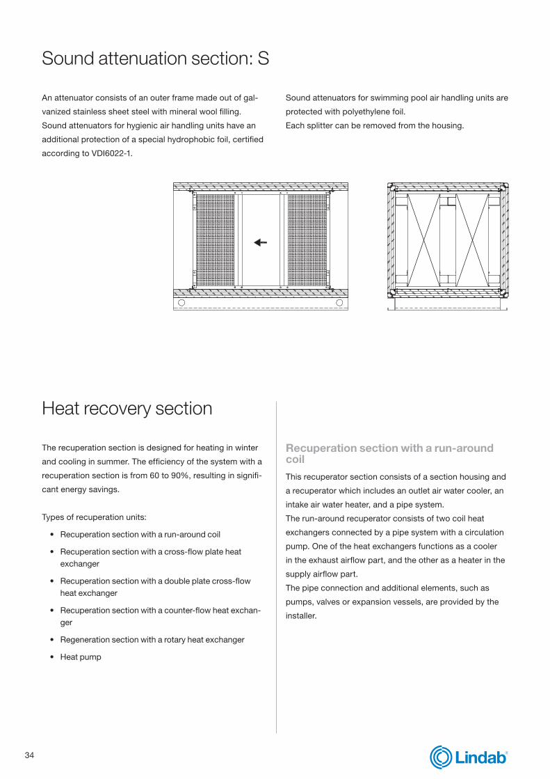
An attenuator consists of an outer frame made out of gal-
vanized stainless sheet steel with mineral wool filling.
Sound attenuators for hygienic air handling units have an
additional protection of a special hydrophobic foil, certified
according to VDI6022-1.
Sound attenuators for swimming pool air handling units are
protected with polyethylene foil.
Each splitter can be removed from the housing.
Heat recovery section
The recuperation section is designed for heating in winter
and cooling in summer. The efficiency of the system with a
recuperation section is from 60 to 90%, resulting in signifi-
cant energy savings.
Types of recuperation units:
• Recuperation section with a run-around coil
• Recuperation section with a cross-flow plate heat exchanger
• Recuperation section with a double plate cross-flow heat exchanger
• Recuperation section with a counter-flow heat exchan-ger
• Regeneration section with a rotary heat exchanger
• Heat pump
Recuperation section with a run-around coilThis recuperator section consists of a section housing and
a recuperator which includes an outlet air water cooler, an
intake air water heater, and a pipe system.
The run-around recuperator consists of two coil heat
exchangers connected by a pipe system with a circulation
pump. One of the heat exchangers functions as a cooler
in the exhaust airflow part, and the other as a heater in the
supply airflow part.
The pipe connection and additional elements, such as
pumps, valves or expansion vessels, are provided by the
installer.

35
l indab | modular air handling units
Recuperation section with a heating coil: RKE
Pipe connection dimensions depend on individual air handling unit sizes and other input parameters.
6/3 - 30/21
6/3 - 30/21
21/24 - 30/27
21/24 - 30/27
Recuperation section with a cooling coil: RKK
36
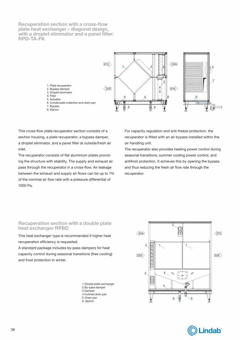
Recuperation section with a cross-flow plate heat exchanger – diagonal design, with a droplet eliminator and a panel filter: RPD-TA-FK
This cross-flow plate recuperator section consists of a
section housing, a plate recuperator, a bypass damper,
a droplet eliminator, and a panel filter at outside/fresh air
inlet.
The recuperator consists of flat aluminium plates provid-
ing the structure with stability. The supply and exhaust air
pass through the recuperator in a cross-flow. Air leakage
between the exhaust and supply air flows can be up to 1%
of the nominal air flow rate with a pressure differential of
1000 Pa.
For capacity regulation and anti-freeze protection, the
recuperator is fitted with an air bypass installed within the
air handling unit.
The recuperator also provides heating power control during
seasonal transitions, summer cooling power control, and
antifrost protection. It achieves this by opening the bypass
and thus reducing the fresh air flow rate through the
recuperator.
Recuperation section with a double plate heat exchanger RPBDThis heat exchanger type is recommended if higher heat
recuperation efficiency is requested.
A standard package includes by-pass dampers for heat
capacity control during seasonal transitions (free cooling)
and frost protection in winter.
1. Double plate exchanger2. By-pass damper3. Damper4. Inclined drain pan5. Drain pan6. Siphon
1. Plate recuperator2. Bypass damper3. Droplet eliminator4. Filter5. Actuator6. Condensate collection and drain pan7. Bypass8. Siphon

37
l indab | modular air handling units
Recuperation section with a counter-flow heat exchanger RPDCCounter-flow heat exchangers have higher efficiencies in
comparison with cross-flow heat exchangers.
• Recovery of sensible heat from the outlet to the inlet
(fresh) air flow, recovery efficiency over 90%
• Airtightness between inlet and outlet air flow
It consists of:
• An aluminium filler from shaped flat plates which can be
epoxy-coated upon request.
• Galvanized steel sheet side panels which can be epoxy-
coated upon request, as well as additional corner
connection profiles.
Recuperation section with a rotary heat exchanger: RRGThis recuperation section consists of a section housing
and a rotary regenerative wheel.
The rotary wheel is installed into the section housing, from
which it can be removed in one piece, or, in case of large
sections, in segments.
Two stage design
Parallel design

38
high pressure
low pressure
manometer
discharge line
loquid line
rotalock valve
sensorevaporator
condenser
electronic expansion valve
sensor
sensor
ZRD or ZPDdigitalcompressor
rotalock valve
reservoire
filter drier
liquid indicator
suction line
manometer
Heat pumpThe heat pump or cooling system consists of the basic
elements that are described in individual section chapters
(evaporator, condenser, compressor), as well as elements
for the regulation, control and protection of the system.
Depending on the installation of an evaporator or a
condenser on the supply side of the air handling unit, the
system can be used for cooling, heating or even for cooling
and heating, depending on the season.

39
l indab | modular air handling units
Controls
Control systemAir handling units can be supplied with a complete control
system. Our services include:
• Technical support to designers
• Remote control
• Design and construction of electric Control cabinets
• Wiring
• Functional start-up of air handling units in the factory
• Optional: final start-up on site as a separate service on request
AutomationTo ensure the optimum operation of HVAC systems, we
use control equipment with standard software compatible
with cloud solutions. As a result, we can offer tailored
solutions for even the most complex and comprehensive
HVAC systems and issue unique functional warranties for
individual projects.
As peripheral equipment, we install elements by leading
manufacturers, e.g. Belimo, Danfoss, Carel, Regin, etc.
Remote operationAn integrated TCP/IP server, remote displays and touch-
screens allow simple and user-friendly operation of our
air handling units and comprehensive HVAC systems
and offer an overview of system functions in an internet
browser. On request, we can also include system visualiza-
tion.
Electric control cabinetsWe design and manufacture in-house electric control cabi-
nets to provide complete adaptability to the requirements
of the customer or the project.
The cabinets can be installed internally or externally and
contain all power and control elements.
During production, each electric control cabinet undergoes
a power test and functional test.
Wiring in production or on siteThe wiring of the peripheral equipment is carried out in the
factory according to the individual electrical wiring dia-
gram. On request, the wiring can also be carried out on the

40
site of the final installation of the air handling unit.
In case of split delivery of air handling unit sections, the
connectors are pre-prepared in the factory for easier
on-site assembly. All connectors and cables are marked
accordingly.
The heating and cooling circuit pipe installation with
valves, pumps, manometers, etc. can also be fitted in the
factory, to simplify the on-site installation.
Functional start-upThe functional start-up includes setting all project para-
meters and testing all air handling unit functions according
to the requirements of the project.
Upon completing the start-up, the customer receives com-
plete documentation describing system operation and all
warranty statements.
For all air handling units where Lindab supplies the control
system we issue a functional warranty.
On request, the final start-up can also be carried out on site.
Continuous management of cooling powerCompressors with linear driven capacity:
• Digital scroll compressors
• BLDC compressors
Advantages:
• Higher load possibility
• Precise temperature regulation (+/-0.5°C)
• Precise humidity regulation
• Higher level of system stability
• Decreased power consumption
Digital scroll compressors
• Copeland compressors
• Emersson controller
• Capacity regulation 10–100%
• Integrated regulation of the DX electronic expansion
valve
Integration in a building management system (BMS)The software provides:
• A user-friendly graphical overview of the entire system
• Event and alarm database management
• Overview of alarms
• Overview of trends
• Overview of events
• Alarm and event management
• Calendar and scheduled operation
• Report editor
• Access right management
• Modem or internet communication
The software integrates all communications protocols,
commonly used for HVAC, such as:
• Modbus
• BacNet
• Lon Works
• Exoline

41
l indab | modular air handling units

At Lindab we simplify construction for our custo-
mers. We do that by designing easy-to-use produ-
cts and solutions, as well as offering efficient availa-
bility and logistics. We are also working on ways to
reduce our impact on our environment and climate.
We do that by developing methods to produce our
solutions using a minimum of energy and natural
resources, and by reducing negative effects on the
environment. We use steel in our products. It’s one
of few materials that can be recycled an infinite
number of times without losing any of its properties.
That means less carbon emissions in nature and
less energy wasted.
We simplify construction
Tel: 01604 788363Email: [email protected]/ahu