linear diffusers - lindab - we simplify construction · 2016-02-11 · km series linear diffusers...
TRANSCRIPT

LINEAR DIFFUSERSKM
SERIES OVERVIEW
CHARACTERISTICS APPLICATIONS
OVERVIEW :KM series linear diffusers are an excellent solution as air terminal devices. They are made in anodized aluminium and they are equipped with adjustable deflectors. These deflectors permit to obtain multidirectional flow of delivery air and the optimization of diffuser perfomance in the specific application. This kind of diffusers is suggested for all civil applications that require linear and specific air diffusion. KM series is designed to be installed without mounting frame and without screws on frontal side. This kind of linear diffuser can be manufactured with a maximum of 8 slots in order to satisfy all possible applications.
CHARACTERISTICS AND OPERATION :KM diffusers are equipped with adjustable deflector blades which permit high induction level. The possibility to change air flow direction into a range of 180 degree, leave costant the value of pressure drop and free area of ATD. Deflectors divide the main air flow to several vertical and horizontal air jets which cause a high induction effect. It's possible to obtain combined jets (vertical and horizontal, left and right) with the same slot
DIFFUSER FIXING TO THE CEILING : S2 mounting system (shown on following pages) is constituted from supports fixed on diffusor's lateral sides. These supports are joined to the ceiling by a traction system. This sistem can substain the plenum.S3 mounting system is constituted from supports fixed on diffusor lateral sides. In this case, these supports connect the diffusor to the plenum that is fixed to the ceiling.
DIFFUSER FIXING TO THE PLENUM :S2 mounting system is carried out by self-threading screws applied to lateral sides of diffuser body.S3 mounting system is fixed by mounting bridges.
STANDARD FINISHING : KM series diffuser can be manufactured from anodized extruded aluminium or from extruded aluminium painted with colour white RAL 9010 (epoxy powder treatment).
MATERIALS : Diffuser in extruded aluminium, plenum in galvanized sheet steel external insulation self extinguishing material class 1same slot.
APPLICATIONS :Generally, KM series diffusers are installed on the ceiling for civil buildings which have a mixed air distribution system. The installation height is included between 2,6 and 6,0 m. The air flow rate is variable from 200 to 1.400 m3/h with temperature gradient between +15 C and –10 C.
steel, external insulation self-extinguishing material class 1.
CONTRAST CALIBRATING GATE : The regulation is carried out by a command inside the diffuser.
U08 Diffusion-vers.14.00.xls U08-1

LINEAR DIFFUSERSKM
SERIESTECHNICAL DRAWINGS
KM 1 slot linear diffuser KM 2 slots linear diffuser.
KM 3 slots linear diffuser.
KM 4 slots linear diffuser.
U08 Diffusion-vers.14.00.xls U08-2
LINEAR DIFFUSERSKM
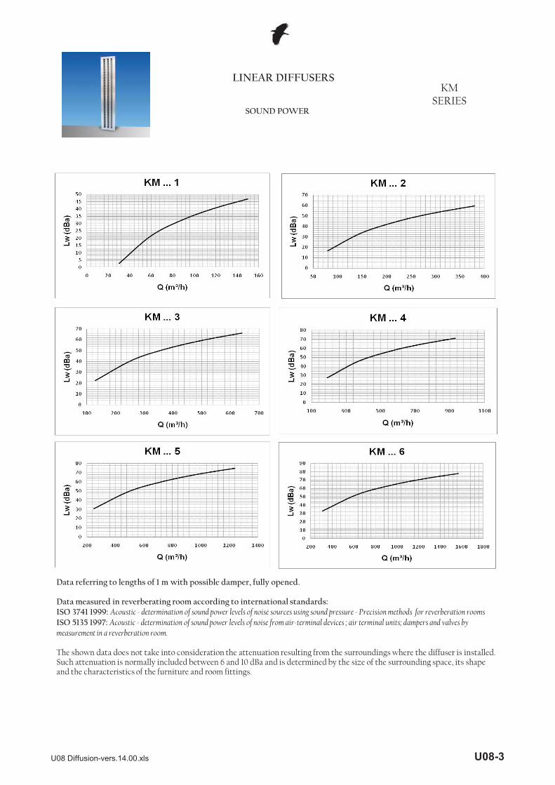
SERIESSOUND POWER
Data referring to lengths of 1 m with possible damper, fully opened.
Data measured in reverberating room according to international standards:ISO 3741 1999: Acoustic - determination of sound power levels of noise sources using sound pressure - Precision methods for reverberation roomsISO 5135 1997: Acoustic - determination of sound power levels of noise from air-terminal devices ; air terminal units; dampers and valves by measurement in a reverberation room.
The shown data does not take into consideration the attenuation resulting from the surroundings where the diffuser is installed.Such attenuation is normally included between 6 and 10 dBa and is determined by the size of the surrounding space, its shape and the characteristics of the furniture and room fittings.
U08 Diffusion-vers.14.00.xls U08-3
LINEAR DIFFUSERSKM
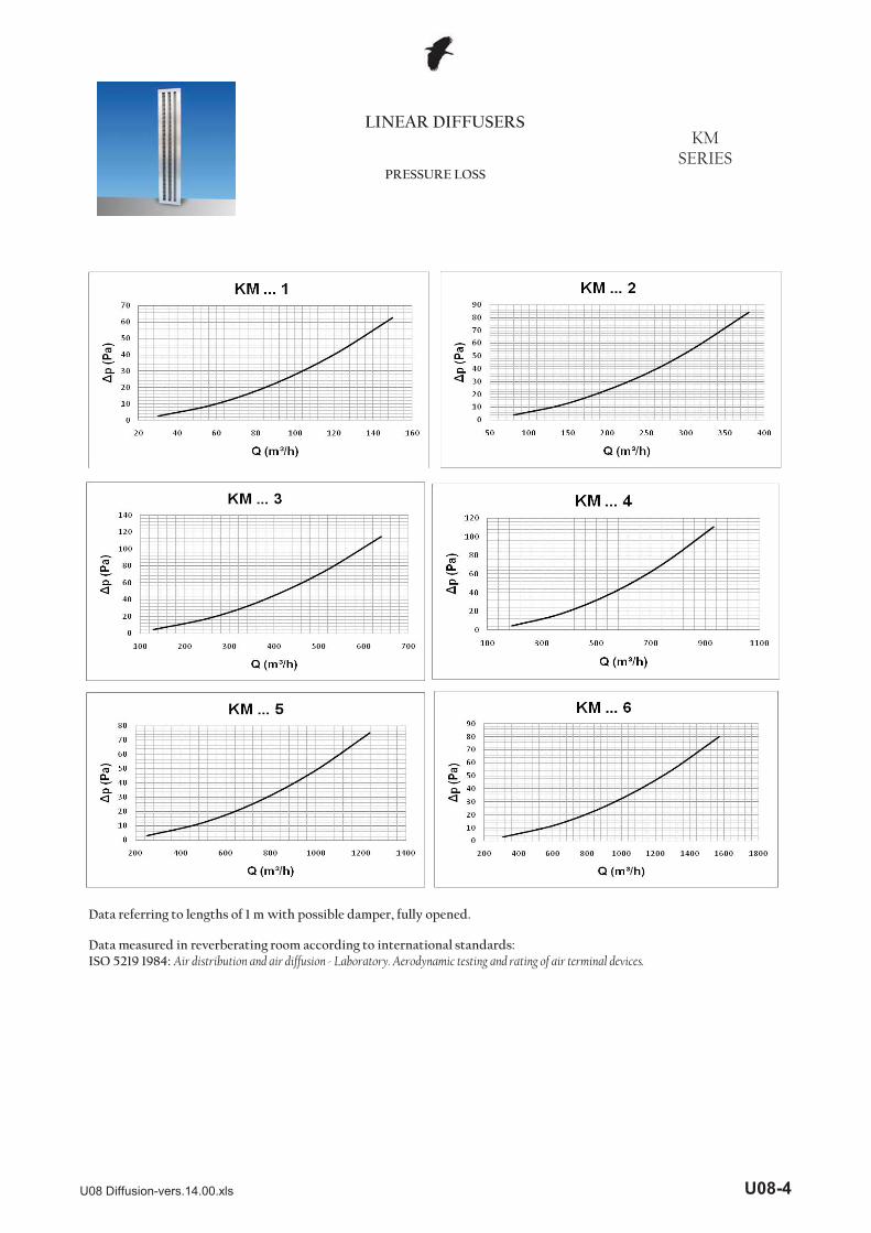
SERIESPRESSURE LOSS
Data referring to lengths of 1 m with possible damper, fully opened.
Data measured in reverberating room according to international standards:ISO 5219 1984: Air distribution and air diffusion - Laboratory. Aerodynamic testing and rating of air terminal devices.
U08 Diffusion-vers.14.00.xls U08-4

LINEAR DIFFUSERSKM
SERIESAERAULIC DATA
Data referring to lengths of 1 m with possible damper, fully opened.
Data measured in reverberating room according to international standards:ISO 5219 1984: Air distribution and air diffusion - Laboratory. Aerodynamic testing and rating of air terminal devices.
L (m) horizontal distance in metres from the centre of the diffuserVl (m/s) maximum speed inside the air stream
U08 Diffusion-vers.14.00.xls U08-5

LINEAR DIFFUSERSKM
SERIESTECHNICAL DATA
KMLinear diffusers with fixing supports and plenum.
2000 2020 2060
1000 1020 10601500 1520 1560
L L + 20 L + 60800 820 860
3 144 155,54 183 194,5
1 66 77,52 105 116,5
slots n° B C
U08 Diffusion-vers.14.00.xls U08-6
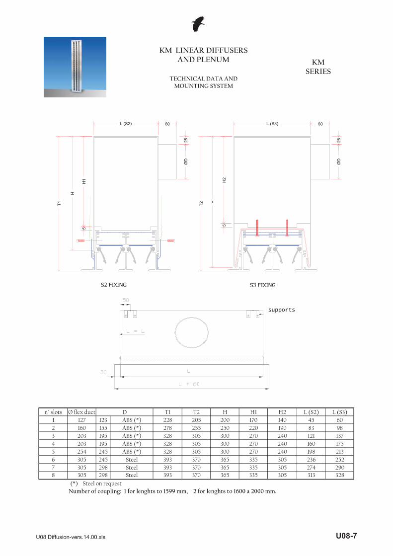
KM LINEAR DIFFUSERS AND PLENUM
TECHNICAL DATA AND MOUNTING SYSTEM
KM SERIES
L (S2)
H
H1
5
L (S3)
H2
H
5
FISSAGGIO tipo S3
ØD
25
60 60
25Ø
D
T1 T2
FISSAGGIO tipo S2S2 FIXING S3 FIXING
123155195195245245298298
(*) Number of coupling: 1 for lenghts to 1599 mm, 2 for lenghts to 1600 a 2000 mm.
8 305 393 3707 305 Steel
Steel365 335
335
335365 305
365 328305 274 290305
252
313
2365 254 328 3056 305 393 370
240 160 175300 270 240 198 213
4 203 328 305 300 270
98300 270 240 1213 203 328 305 137
45 602 160 278 255 250 220 190 83
H2 L (S2) L (S3)1 127 228 205 200 170 140
n° slots Ø flex duct T1 T2 H H1D
Steel on request
ABS (*)ABS (*)ABS (*)ABS (*)ABS (*)
Steel393 370
S2 FIXING S3 FIXING
supports
U08 Diffusion-vers.14.00.xls U08-7

AB
DE
--R
KM A 2 1000 R
length
KM SERIES
KM Linear diffuser
KM LINEAR DIFFUSERS AND PLENUM
HOW TO ORDER
with equalizer, sliding damper and deflectors
anodized profileRAL 9010 profile
with sliding damper and deflectors
diffuser profile only
C
number of slots (form 1 up to 8)
with sliding damper (without deflectors)with deflectors
5678
1000 mm1500 mm All intermediate sizes are available on request2000 mm
--R
R
7 2 1000
S2 fixing - insulatedS2 fixing - not insulatedS3 fixing - insulatedS3 fixing - not insulated
Standard lengths:800 mm
P9 Plenum for diffuser KM
AN
AN Angle junction
anodized profileRAL 9010 profile
number of slots (form 1 up to 8)
length
number of slots (form 1 up to 8)
P9
2
U08 Diffusion-vers.14.00.xls U08-8
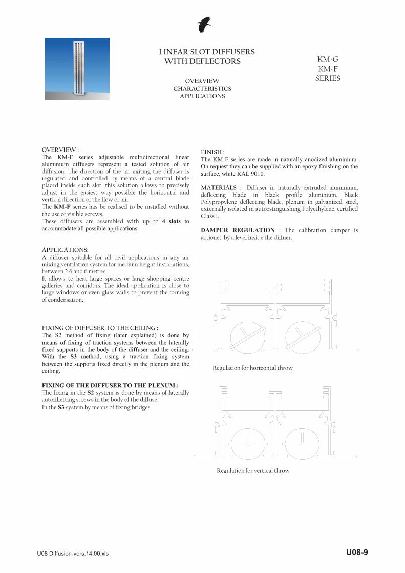
LINEAR SLOT DIFFUSERS WITH DEFLECTORS KM-G
KM-F SERIESOVERVIEW
CHARACTERISTICS APPLICATIONS
OVERVIEW :The KM-F series adjustable multidirectional linearaluminium diffusers represent a tested solution of airdiffusion. The direction of the air exiting the diffuser isregulated and controlled by means of a central bladeplaced inside each slot. this solution allows to preciselyadjust in the easiest way possible the horizontal andvertical direction of the flow of air.The KM-F series has be realised to be installed withoutthe use of visible screws.These diffusers are assembled with up to 4 slots toaccommodate all possible applications.
APPLICATIONS:A diffuser suitable for all civil applications in any airmixing ventilation system for medium height installations,between 2.6 and 6 metres.It allows to heat large spaces or large shopping centregalleries and corridors. The ideal application is close tolarge windows or even glass walls to prevent the forming
FINISH :The KM-F series are made in naturally anodized aluminium.On request they can be supplied with an epoxy finishing on thesurface, white RAL 9010.
MATERIALS : Diffuser in naturally extruded aluminium,deflecting blade in black profile aluminium, blackPolypropylene deflecting blade, plenum in galvanized steel,externally isolated in autoestinguishing Polyethylene, certifiedClass 1.
DAMPER REGULATION : The calibration damper isactioned by a level inside the diffuer.
g g p gof condensation.
FIXING OF DIFFUSER TO THE CEILING :The S2 method of fixing (later explained) is done bymeans of fixing of traction systems between the laterallyfixed supports in the body of the diffuser and the ceiling.With the S3 method, using a traction fixing systembetween the supports fixed directly in the plenum and theceiling.
FIXING OF THE DIFFUSER TO THE PLENUM :The fixing in the S2 system is done by means of laterallyautofilletting screws in the body of the diffuse.In the S3 system by means of fixing bridges.
Regolazione per lancio orizzontale
Regolazione per lancio verticale
Regulation for horizontal throw
Regulation for vertical throw
U08 Diffusion-vers.14.00.xls U08-9

LINEAR SLOT DIFFUSERS WITH DEFLECTORS KM-G
KM-F SERIESCONSTRUCTION DIAGRAMS
Single slot KM linear diffuser. Two slots KM linear diffuser.
Three slots KM linear diffuser.
124
117
53,6
78,5
85,5
115,8
21 2117,5 28,1528,152128,15 28,15
77,3
53,6
40
47
Four slots KM linear diffuser.
53,6
2121 17,5 2117,5 28,15
152,5
21 17,528,15
192,8
162,5
53,6
21
154,3
21 17,5 28,1517,52128,15
U08 Diffusion-vers.14.00.xls U08-10

SINGLE SLOT DIFFUSER: data based on the height of the ceiling of 3m in isothermal conditions.
LINEAR SLOT DIFFUSERS WITH DEFLECTORS KM-G
KM-F SERIESFUNCTIONAL CHARACTERISTICS
THROW VALUES SINGLE SLOT DIFFUSER
Regulation for horizontal throwThe diagram allows to obtain the airspeed at the limit of the occupied area(1,8m from the floor) in relation to thedistance L between the diffusers andthe air flow per meter of the diffuser.For diffusers with lengths different to1m the exiting air flow must beregulated divided by the diffuser lengthshown in metres.Example:length: 1,5mair flow: 300m³/h300 / 1,5 = 200air flow per metre: 200m³/h
Speed at height of 1.8m from floor (m/s)
Dis
tanc
eL b
etw
een
diffu
sers
(m)
R l ti f ti l th
Vt(m/s)
0.1 0.2 0.3 0.4 0.5
L(m
)
2
4
6
8
10
40(m³/h)
60(m³/h)
80(m³/h)
100(m³/h)
120(m³/h)
140(m³/h)
Speed at distance Y from the ceiling (m/s)
Dis
tanc
e Y
from
the
ceilin
g (m
)
Regulation for vertical throwThe diagram allows to obtain the air speed in variation to the distance from the diffuser.For diffusers with lengths different to1m the exiting air flow must beregulated divided by the diffuser lengthshown in metres.Example:length: 1,5mair flow: 300m³/h300 / 1,5 = 200air flow per metre: 200m³/h
Aufenthalts-Bereich
Vt
1.8m3m
L(m)
Vt
y(m)
OCCUPIED ZONE
Vt(m/s)
0.2 0.4 0.6 0.8 1.0 1.2 1.5
y(m
)
0.5
1
1.5
2
3
40(m³/h)
60(m³/h)
80(m³/h)
100(m³/h)
120(m³/h)
140(m³/h)
U08 Diffusion-vers.14.00.xls U08-11

LINEAR SLOT DIFFUSERS WITH DEFLECTORS KM-G
KM-F SERIESFUNCTIONAL CHARACTERISTICS
THROW VALUES TWO SLOTS DIFFUSER
TWO SLOTS DIFFUSER: data based on the height of the ceiling of 3m in isothermal conditions.
Dis
tanc
eL b
etw
een
diffu
sers
(m)
Speed at height of 1.8m from floor (m/s)
R l i f i l h
Regulation for horizontal throwThe diagram allows to obtain the airspeed at the limit of the occupied area(1,8m from the floor) in relation to thedistance L between the diffusers andthe air flow per meter of the diffuser.For diffusers with lengths different to1m the exiting air flow must beregulated divided by the diffuser lengthshown in metres.Example:length: 1,5mair flow: 300m³/h300 / 1,5 = 200air flow per metre: 200m³/h
Vt(m/s)
0.1 0.2 0.3 0.4 0.5 0.6 0.8
L(m
)
2
3
4
5
6
7
89
10
160(m³/h)
180(m³/h)
80(m³/h)
100(m³/h)
120(m³/h)
140(m³/h)
Dis
tanc
e Y
from
the
ceilin
g (m
)
Speed at distance Y from the ceiling m/s)
Regulation for vertical throwThe diagram allows to obtain the air speed in variation to the distance from the diffuser.For diffusers with lengths different to1m the exiting air flow must beregulated divided by the diffuser lengthshown in metres.Example:length: 1,5mair flow: 300m³/h300 / 1,5 = 200air flow per metre: 200m³/h
Aufenthalts-Bereich
Vt
1.8m3m
L(m)
Vt
y(m)
OCCUPIED ZONE
Vt(m/s)
0.2 0.4 0.60.6 0.8 1.0 1.2 1.5 2.0
y(m
)
0.5
1
1.5
2
2.5
3
160(m³/h)
180(m³/h)
80(m³/h)
100(m³/h)
120(m³/h)
140(m³/h)
U08 Diffusion-vers.14.00.xls U08-12

LINEAR SLOT DIFFUSERS WITH DEFLECTORS KM-G
KM-F SERIESFUNCTIONAL CHARACTERISTICS
THROW VALUES THREE SLOTS DIFFUSER
THREE SLOTS DIFFUSER: data based on the height of the ceiling of 3m in isothermal conditions.
R l i l i i t l
Dis
tanc
eL b
etw
een
diffu
sers
(m)
Speed at height of 1.8m from floor (m/s)
Regulation for horizontal throwThe diagram allows to obtain the airspeed at the limit of the occupied area(1,8m from the floor) in relation to thedistance L between the diffusers andthe air flow per meter of the diffuser.For diffusers with lengths different to1m the exiting air flow must beregulated divided by the diffuser lengthshown in metres.Example:length: 1,5mair flow: 300m³/h300 / 1,5 = 200air flow per metre: 200m³/h
R l i f i l h
Vt(m/s)
0.2 0.3 0.4 0.5 0.6 0.8 0.9 1.0
L(m
)
2
3
4
5
6
789
10
360(m³/h)
180(m³/h)
240(m³/h)
120(m³/h)
300m³/h)
420(m³/h)
3 Regolazione per lancio orizzontaleIl diagramma consente di ottenere lavelocità dell'aria al limite della zonaoccupata (1,8m dal pavimento) infunzione della distanza L tra i diffusorie della portata d'aria per metro didiffusore.Per lunghezze di diffusore diverse da1m la portata erogata deve essere divisaper la lunghezza del diffusore espressain metriEsempio:lunghezza: 1,5mportata: 500m³/h500 / 1,5 = 333portata per metro: 333m³/h
Dis
tanc
e Y
from
the
ceilin
g (m
)
Speed at distance Y from the ceiling (m/s)
Regulation for vertical throwThe diagram allows to obtain the air speed in variation to the distance from the diffuser.For diffusers with lengths different to1m the exiting air flow must beregulated divided by the diffuser lengthshown in metres.Example:length: 1,5mair flow: 300m³/h300 / 1,5 = 200air flow per metre: 200m³/h
Aufenthalts-Bereich
Vt
1.8m3m
L(m)
Vt
y(m)
OCCUPIED ZONE
Vt(m/s)
0.2 0.4 0.6 0.9 1.2 1.5 1.82.0 2.5
y(m
)
0.5
1
1.5
2
2.5
3
360(m³/h)
180(m³/h)
240(m³/h)
120(m³/h)
300m³/h)
420(m³/h)
U08 Diffusion-vers.14.00.xls U08-13

LINEAR SLOT DIFFUSERS WITH DEFLECTORS KM-G
KM-F SERIESFUNCTIONAL CHARACTERISTICS
THROW VALUES FOUR SLOTS DIFFUSER
FOUR SLOTS DIFFUSER: data based on the height of the ceiling of 3m in isothermal conditions.
Dis
tanc
eL b
etw
een
diffu
sers
(m)
Speed at height of 1.8m from floor (m/s)
Regulation for horizontal throwThe diagram allows to obtain the airspeed at the limit of the occupied area(1,8m from the floor) in relation to thedistance L between the diffusers andthe air flow per meter of the diffuser.For diffusers with lengths different to1m the exiting air flow must beregulated divided by the diffuser lengthshown in metres.Example:length: 1,5mair flow: 300m³/h300 / 1,5 = 200air flow per metre: 200m³/h
Regulation for ertical thro3
Vt(m/s)
0.2 0.3 0.4 0.5 0.6 0.8 0.9 1.0
L(m
)
2
3
4
5
6
789
10
480(m³/h)
240(m³/h)
320(m³/h)
160(m³/h)
400m³/h)
560(m³/h)
Dis
tanc
e Y
from
the
ceilin
g (m
)
Speed at distance Y from the ceiling (m/s)
Regulation for vertical throwThe diagram allows to obtain the air speed in variation to the distance from the diffuser.For diffusers with lengths different to1m the exiting air flow must beregulated divided by the diffuser lengthshown in metres.Example:length: 1,5mair flow: 300m³/h300 / 1,5 = 200air flow per metre: 200m³/h
Aufenthalts-Bereich
Vt
1.8m3m
L(m)
Vt
y(m)
OCCUPIED ZONE
Vt(m/s)
0.2 0.4 0.6 0.9 1.2 1.5 1.82.0 2.5
y(m
)
0.5
1
1.5
2
2.5
3
360(m³/h)
180(m³/h)
240(m³/h)
120(m³/h)
300m³/h)
420(m³/h)
U08 Diffusion-vers.14.00.xls U08-14

LINEAR SLOT DIFFUSERS WITH DEFLECTORS KM-G
KM-F SERIESFUCTIONAL CHARACTERISTIC
AIR FLOW LOSS
0
50
100
150
200
250
300
�p(P
a)
Blade regulated for vertical throw
Blade regulated for horizontal throw
Single slot diffuserThe diagrams allows to obtain thepressure loss per linear metre of thediffuser in relation to the air flow inboth the conditions of regulation ofthe deflecting blade.The regulation for a horizontal thouwallows larger air flows.
Vertical throw: horizontal bladeHorizontal throw: completely tiltedblade
For diffuser lengths differnt to onemetre, consider the air flow per metreof diffuser.
Example:length: 1,5mair flow: 300m³/hair flow per metre: 200m³/h
0 50 100 150 200 250 300
Q(m³/h)
0
50
100
150
200
250
300
0 100 200 300 400 500 600
�p(P
a)
Q(m³/h)
Blade regulated for horizontal throw
Blade regulated for vertical throw
Single slot diffuserThe diagrams allows to obtain thepressure loss per linear metre of thediffuser in relation to the air flow inboth the conditions of regulation of thedeflecting blade.The regulation for a horizontal thouwallows larger air flows.
Vertical throw: horizontal bladeHorizontal throw: completely tiltedblade
For diffuser lengths differnt to onemetre, consider the air flow per metreof diffuser.
Example:length: 1,5mair flow: 300m³/hair flow per metre: 200m³/h
U08 Diffusion-vers.14.00.xls U08-15

LINEAR SLOT DIFFUSERS WITH DEFLECTORS KM-G
KM-F SERIESFUCTIONAL CHARACTERISTIC
AIR FLOW LOSS
0
50
100
150
200
250
300
0 100 200 300 400 500 600 700 800
�p(P
a)
Blade regulated for horizontal throw
Blade regulated for vertical throw
Single slot diffuserThe diagrams allows to obtain thepressure loss per linear metre of thediffuser in relation to the air flow inboth the conditions of regulation ofthe deflecting blade.The regulation for a horizontal thouwallows larger air flows.
Vertical throw: horizontal bladeHorizontal throw: completely tiltedblade
For diffuser lengths differnt to onemetre, consider the air flow per metreof diffuser.
Example:length: 1,5mair flow: 300m³/hair flow per metre: 200m³/h
0 100 200 300 400 500 600 700 800
Q(m³/h)
0
50
100
150
200
250
300
0 200 400 600 800 1000 1200
�p(P
a)
Q(m³/h)
Blade regulated for horizontal throw
Blade regulated for vertical throw
Single slot diffuserThe diagrams allows to obtain thepressure loss per linear metre of thediffuser in relation to the air flow inboth the conditions of regulation of thedeflecting blade.The regulation for a horizontal thouwallows larger air flows.
Vertical throw: horizontal bladeHorizontal throw: completely tiltedblade
For diffuser lengths differnt to onemetre, consider the air flow per metreof diffuser.
Example:length: 1,5mair flow: 300m³/hair flow per metre: 200m³/h
U08 Diffusion-vers.14.00.xls U08-16

LINEAR SLOT DIFFUSERS WITH DEFLECTORS KM-G
KM-F SERIESTECHNICAL DATA
Data measured in reverberation room in accordance with international standards:ISO 3741 1999: Acoustic - determination of sound power levels of noise sources using sound pressure - Precision methods for reverberation rooms
ISO 5135 1997: Acoustic - determination of sound power levels of noise from air-terminal devices ; air terminal units; dampers and valves by measurement in a reverberation room.
The data presented does not consider the attenuation given by the area of installation. This attenuation is normally between 6 and 10 dBA and is determined by the room size, the shape of the environment and the interior features.
30
35
40
45
50
55
60
50 70 90 110 130 150 170
Lw (d
ba)
Q (m³/h)
1 slot - sound power
30
35
40
45
50
55
60
50 100 150 200 250 300
Lw (d
ba)
2 slots - sound power
50 100 150 200 250 300
Q (m³/h)
30
35
40
45
50
55
60
150 200 250 300 350 400
Lw (d
ba)
Q (m³/h)
3 slots - sound power
30
35
40
45
50
55
60
150 200 250 300 350 400 450 500
Lw (d
ba)
Q (m³/h)
4 slots - sound power
U08 Diffusion-vers.14.00.xls U08-17

LINEAR SLOT DIFFUSERS WITH DEFLECTORS KM-G
KM-F SERIESINSTALLATION CHARACTERISTICS
PLENUM CONNECTION
L (S2)
H
H1
5
L (S3)
H2
H
5
ØD
25
60 60
25Ø
D
(*)
1604 245 300 270 240 175240 137 121
2 1953 195 300 270
300
L (S2)4583
60270 240 98
H2240
L (S3)
Fixing type S2 Fixing type S3
1 155 300 270N° slots ØD
ABS(*)ABS(*)ABS(*)ABS(*)
Steel on request
H H1
U08 Diffusion-vers.14.00.xls U08-18

FG
--R
2 1000 R
Linear diffuser
without damperwith sliding damper
KM
LINEAR SLOT DIFFUSERS WITH DEFLECTORS KM-G
KM-F SERIESHOW TO ORDER
anodized profileRAL 9010 profile
F
number of slots (from 1 up to 8)
length
KM
5678
1000 mm1500 mm All intermediate sizes are available on request2000 mm
--R
P9 7 2 1000
RAL 9010 profile
AN 2 R
Standard lengths:800 mm
AN Angle junction
number of slots (from 1 up to 8)
anodized profile
S3 fixing - not insulated
P9 Plenum for diffuser KM
S2 fixing - insulated
number of slots (from 1 up to 8)
length
S2 fixing - not insulatedS3 fixing - insulated
U08 Diffusion-vers.14.00.xls U08-19

U08 Diffusion-vers.14.00.xls U08-20

LINEAR SLOT DIFFUSERSKL
SERIESOVERVIEW
CHARACTERISTICS APPLICATIONS
OVERVIEW :The KL series diffusers represent the best development for this type of air diffusion units.Their particular structure allows to direct the flow of injected air along the ceiling. The effect is one of a progressive mix with the air in the room without the need of creating air currents or air vortexes that may be perceptible even in cooling mode. In contrast it is possible to direct the flow of injected air rapidly towards the floor, with a large forcing action to obtain a rapid heating of the room.The modular structure allows for an unlimited number of rows, parallel slots, without any visible joint line showing.The KL series diffusers stand out thanks to their innovative design, characterised by its soft lines and curved edges, not purely for aesthetic value. It is a result of accurate fluid dynamic studies, carried out using innovative mathematic models, aimed at optimizing the distribution of the speed of air exiting the diffuser.The KLV series diffusers are complemented with their own line of plenum boxes made in such a way that when i lli i l l i i d f
FITTING OF THE DIFFUSER: The KL diffusers are fitted with specific plenums by means of suspension springs or with mounting bridges.This allows for a rapid fitting even after all masonry work has been completed.
FINISH: The KL diffusers are constructed with an anodized or RAL 9010 painted aluminium body with deflecting blades also painted black or white RAL9010.Other special finishes may be provided upon request.
MATERIALS: Diffuser completely in naturally anodized extruded aluminium, plenum from galvanized steel sheet and external insulation in self-extinguishing Class1 material.
VERSIONS : KLV Series: identifiable from the large area that allows to minimise the pressure loss and noise even at elevated air flow
installing, no particular tools or accessories are required for the job.
WORKING CHARACTERISTICS:The KL series diffusers are made of a diffuser body constructed in aluminium, housing the various air expulsion slots and a series of deflecting blades, also in aluminium, for horizontal or vertical orientation flow of the air. The direction may be easily adjusted without the need to remove the diffuser itself.The body of the diffuser may be integrated with a regulation damper having small square holes. This solution has been studied so as to obtain a precise calibration of the quantity of air injected into the room and at the same time, to reduce to a minimum the pressure loss with the damper fully opened.
APPLICATIONS:The KL diffuser series are used in ventilations systems in facilities where the ceiling height is between 3 and 6 meters, such as open space offices, commercial galleries and hospital wards.The achievable air flows vary in relation to the length of the diffuser and the number of slots. The capacities are included between 50m³/h and 120m³/h per meter per slot with temperature grades varying between +15 °C end I –10 °C.
pcapacities.Adjustment can be made to the air flow via a damper in the plenum connector. KLS Series: identifieable by the possibility of installing sliding regulation dampers inside the body of the diffuser to allow adjustment to the air flow individually for each linear slot.
KLV
KLS
U08 Diffusion-vers.14.00.xls U08-21
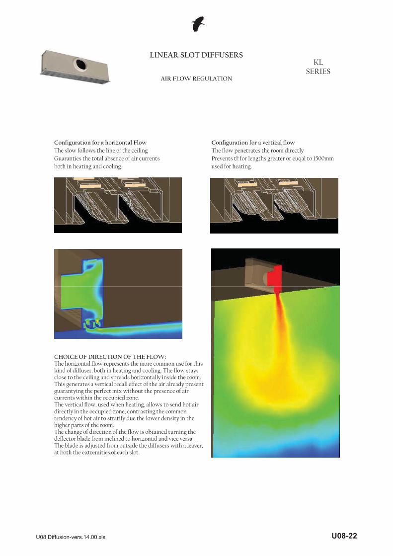
Configuration for a horizontal Flow Configuration for a vertical flowThe slow follows the line of the ceiling The flow penetrates the room directlyGuaranties the total absence of air currents Prevents thfor lengths greater or euqal to 1500mmboth in heating and cooling. used for heating.
LINEAR SLOT DIFFUSERSKL
SERIESAIR FLOW REGULATION
CHOICE OF DIRECTION OF THE FLOW:The horizontal flow represents the more common use for this kind of diffuser, both in heating and cooling. The flow stays close to the ceiling and spreads horizontally inside the room. This generates a vertical recall effect of the air already present guarantying the perfect mix without the presence of air currents within the occupied zone.The vertical flow, used when heating, allows to send hot air directly in the occupied zone, contrasting the common tendency of hot air to stratify due the lower density in the higher parts of the room.The change of direction of the flow is obtained turning the deflector blade from inclined to horizontal and vice versa.The blade is adjusted from outside the diffusers with a leaver, at both the extremities of each slot.
U08 Diffusion-vers.14.00.xls U08-22

LINEAR SLOT DIFFUSERSKL
SERIESDIMENSIONS
efficient section AK
Holes in counter ceilingGiven L as the nominal length of the diffuser, the holes in the counter ceiling will need to be:
Example:1 slot diffuser x 1 slot diffuser L=20002 slot diffuser x hole 2015x57 mm3 slot diffuser x4 slot diffuser x
4 slotsfor a diffuser L=1 m (m²)
1 slot 2 slots 3 slots
efficient section AK
0,03070vertical throw 0,01478 0,02890 0,04328 0,05700
horizontal throw 0,00845 0,01650 0,02287
millimetresL+15 95 millimetres
length widthL+15 57
L+15 134 millimetresL+15 177 millimetres
U08 Diffusion-vers.14.00.xls U08-23

LINEAR SLOT DIFFUSERSKL
SERIESDIMENSIONS
123 123155 155195 195195 195
(*)
OVERALL DIMENSIONSL < 1500 mm 1500� L � 2000 mm
SlotsH S connector ØD connector
1 200 52 1 2mm mm qty mm qty
3 300 130 1 22 250 91 1 2
ABS(*)4 300 172 1 2
Steel on request
ABS(*)ABS(*)ABS(*)ABS(*)
ØDmm
ABS(*)ABS(*)ABS(*)
U08 Diffusion-vers.14.00.xls U08-24
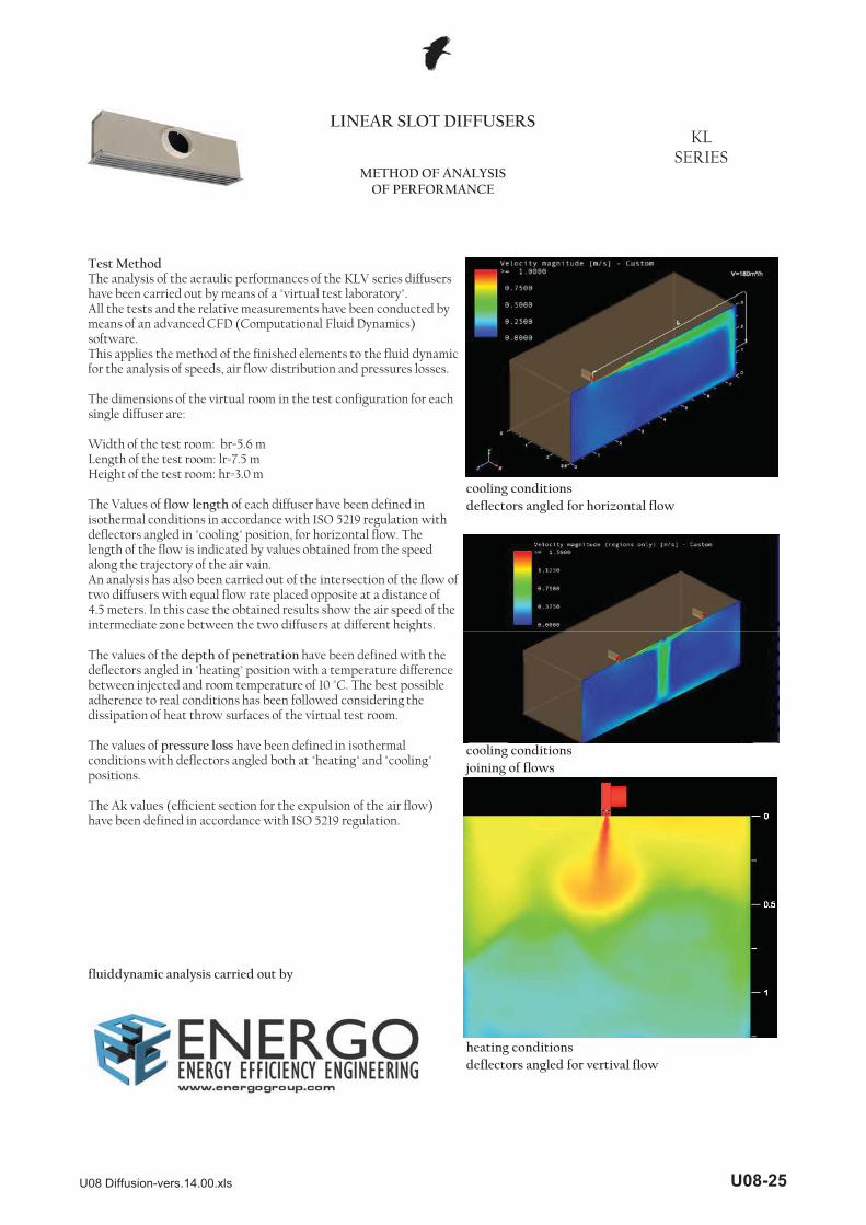
cooling conditionsdeflectors angled for horizontal flow
LINEAR SLOT DIFFUSERSKL
SERIESMETHOD OF ANALYSIS
OF PERFORMANCE
Test MethodThe analysis of the aeraulic performances of the KLV series diffusers have been carried out by means of a "virtual test laboratory".All the tests and the relative measurements have been conducted by means of an advanced CFD (Computational Fluid Dynamics) software.This applies the method of the finished elements to the fluid dynamic for the analysis of speeds, air flow distribution and pressures losses.
The dimensions of the virtual room in the test configuration for each single diffuser are:
Width of the test room: br=5.6 mLength of the test room: lr=7.5 mHeight of the test room: hr=3.0 m
The Values of flow length of each diffuser have been defined in isothermal conditions in accordance with ISO 5219 regulation with deflectors angled in "cooling" position, for horizontal flow. The length of the flow is indicated by values obtained from the speed along the trajectory of the air vain.An analysis has also been carried out of the intersection of the flow of two diffusers with equal flow rate placed opposite at a distance of 4.5 meters. In this case the obtained results show the air speed of the intermediate zone between the two diffusers at different heights.
cooling conditionsjoining of flows
heating conditionsdeflectors angled for vertival flow
g
The values of the depth of penetration have been defined with the deflectors angled in "heating" position with a temperature difference between injected and room temperature of 10 °C. The best possible adherence to real conditions has been followed considering the dissipation of heat throw surfaces of the virtual test room.
The values of pressure loss have been defined in isothermal conditions with deflectors angled both at "heating" and "cooling" positions.
The Ak values (efficient section for the expulsion of the air flow) have been defined in accordance with ISO 5219 regulation.
fluiddynamic analysis carried out by
U08 Diffusion-vers.14.00.xls U08-25

LINEAR SLOT DIFFUSERSKL
SERIESPERFORMANCE
ONE SLOT
Data obtained from CFD mathematical model in a
0
0,1
0,2
0,3
0,4
0,5
0,6
0,7
0,8
0,9
2 3 4 5 6 7 8 9
Vo (m
/s)
A Distance between the diffusers (m)
KL…1 Vo for Hr=3m
50m³/h80m³/h
110m³/h140m³/h
0 6
0,8
1
1,2
n fa
ctor
Kf
KL…1 Correction factor for Hr different to 3m
Fluid dynamic analysis carried out by
Data obtained from CFD mathematical model in a virtual test room, operating in isothermic conditions in accordance with international standard:ISO 5219 1984: Air distribution and air diffusion - Laboratory. Aerodynamic testing and rating of air terminal devices.
A (m) distance between diffusersVo (m/s) speed at external limit of occupied area L (m) horizontal distance in meters from centre of the diffuserVL (m/s) maximum speed in air stream at distance L
For Hr different to 3m, use the multiplier factor KF:Vo (h) = Vo x Kf
0
0,2
0,4
0,6
2 2,5 3 3,5 4 4,5 5 5,5
Corre
ctio
n
Hr Height of the room (m)
0,0
0,1
0,2
0,3
0,4
0,5
0,6
0,7
0 1 2 3 4 5 6 7 8 9 10
VL (m
/s)
L (m)
KL…1 Throw
50m³/h
80m³/h
110m³/h
140m³/h
U08 Diffusion-vers.14.00.xls U08-26

LINEAR SLOT DIFFUSERSKL
SERIESPERFORMANCE
ONE SLOT
Data obtained from CFD mathematical model in a virtual test room operating in heating conditions with �T=10°C in accordance with international standard:ISO 5219 1984: Air distribution and air diffusion - Laboratory. Aerodynamic testing and rating of air terminal devices.H1 (m) vertical distance in meters from the centre of the diffuser where the inversion of the air flow occurs.
Data measured in reverberating room in accordance with the following international standards:ISO 3741 1999: Acoustic - determination of sound power levels of noise sources using sound pressure - Precision methods for
0
0,2
0,4
0,6
0,8
1
1,2
1,4
1,6
1,8
2
40 60 80 100 120 140 160
H1 (m
)
Q (m³/h)
KL…1 Vertical throw �T=10°C
40
45
KLV…1 Sound power
Lw Horizontal f g p freverberation rooms
ISO 5135 1997: Acoustic - determination of sound power levels of noise from air-terminal devices ; air terminal units; dampers and valves by measurement in a reverberation room.
The data shown does not consider the attenuation given by the place of installation. This attenuation is normally included between 6 and 10dBa and is determined by the dimensions of the room, its shape and the arrangements of the furnishings within it.
0
5
10
15
20
25
30
35
40 60 80 100 120 140 160
Lw (d
Ba)
Q (m³/h)
throw
Lw Vertical throw
0
10
20
30
40
50
60
40 60 80 100 120 140 160
Lw (d
Ba)
Q (m³/h)
KLS…1 Sound power
Lw Horizontal throw
Lw Vertical throw
U08 Diffusion-vers.14.00.xls U08-27

LINEAR SLOT DIFFUSERSKL
SERIESPERFORMANCE
ONE SLOT
Data obtained from CFD mathematical model in a virtual test room, operating in isothermic conditions in accordance with international standard:ISO 5219 1984: Air distribution and air diffusion -Laboratory. Aerodynamic testing and rating of air terminal devices.
0
10
20
30
40
50
60
70
80
40 60 80 100 120 140 160
�p (P
a)
Q (m³/h)
KLV…1 Pressure drop
�P Horizontal throw
�P Vertical throw
70
80
90
KLS…1 Pressure drop
�P Horizontal throw
0
10
20
30
40
50
60
40 60 80 100 120 140 160
�p (P
a)
Q (m³/h)
�P Vertical throw
U08 Diffusion-vers.14.00.xls U08-28

LINEAR SLOT DIFFUSERSKL
SERIESPERFORMANCE
TWO SLOTS
0
0,2
0,4
0,6
0,8
1
1,2
1,4
2 3 4 5 6 7 8 9
Vo (m
/s)
A Distance between the diffusers (m)
KL…2 Vo for Hr=3m
90m³/h150m³/h
210m³/h270m³/h
0,8
1
1,2
fact
or K
f
KL…2 Correction factor for Hr different to 3m
Fluid dynamic analysis carried out by
Data obtained from CFD mathematical model in a virtual test room, operating in isothermic conditions in accordance with international standard:ISO 5219 1984: Air distribution and air diffusion - Laboratory. Aerodynamic testing and rating of air terminal devices.
A (m) distance between diffusersVo (m/s) speed at external limit of occupied area L (m) horizontal distance in meters from centre of the diffuserVL (m/s) maximum speed in air stream at distance L
For Hr different to 3m, use the multiplier factor KF:Vo (h) = Vo x Kf
0
0,2
0,4
0,6
2 2,5 3 3,5 4 4,5 5 5,5
Corre
ctio
n f
Hr Height of the room (m)
0,0
0,1
0,2
0,3
0,4
0,5
0,6
0,7
0,8
0,9
0 1 2 3 4 5 6 7 8 9 10
VL (m
/s)
L (m)
KL…2 Throw
90m³/h
150m³/h
210m³/h
270m³/h
U08 Diffusion-vers.14.00.xls U08-29

LINEAR SLOT DIFFUSERSKL
SERIESPERFORMANCE
TWO SLOTS
Data obtained from CFD mathematical model in a virtual test room operating in heating conditions with �T=10°C in accordance with international standard:ISO 5219 1984: Air distribution and air diffusion - Laboratory. Aerodynamic testing and rating of air terminal devices.H1 (m) vertical distance in meters from the centre of the diffuser where the inversion of the air flow occurs.
Data measured in reverberating room in accordance with the following international standards:ISO 3741 1999: Acoustic - determination of sound power levels of noise sources using sound pressure - Precision methods for
0
0,2
0,4
0,6
0,8
1
1,2
1,4
1,6
1,8
50 100 150 200 250 300
H1 (m
)
Q (m³/h)
KL…2 Vertical throw �T=10°C
45
50
KLV…2 Sound power
Lw Horizontal f g p freverberation rooms
ISO 5135 1997: Acoustic - determination of sound power levels of noise from air-terminal devices ; air terminal units; dampers and valves by measurement in a reverberation room.
The data shown does not consider the attenuation given by the place of installation. This attenuation is normally included between 6 and 10dBa and is determined by the dimensions of the room, its shape and the arrangements of the furnishings within it.
0
5
10
15
20
25
30
35
40
50 100 150 200 250 300
Lw (d
Ba)
Q (m³/h)
throw
Lw Vertical throw
0
10
20
30
40
50
60
50 100 150 200 250 300
Lw (d
Ba)
Q (m³/h)
KLS…2 Sound power
Lw Horizontal throw
Lw Vertical throw
U08 Diffusion-vers.14.00.xls U08-30

LINEAR SLOT DIFFUSERSKL
SERIESPERFORMANCE
TWO SLOTS
Data obtained from CFD mathematical model in a virtual test room, operating in isothermic conditions in accordance with international standard:ISO 5219 1984: Air distribution and air diffusion -Laboratory. Aerodynamic testing and rating of air terminal devices.
0
10
20
30
40
50
60
70
80
50 100 150 200 250 300
�p (P
a)
Q (m³/h)
KLV…2 Pressure drop
�P Horizontal throw
�P Vertical throw
70
80
90
KLS…2 Pressure drop
�P Horizontal throw
0
10
20
30
40
50
60
50 100 150 200 250 300
�p (P
a)
Q (m³/h)
�P Vertical throw
U08 Diffusion-vers.14.00.xls U08-31

LINEAR SLOT DIFFUSERSKL
SERIESPERFORMANCE
THREE SLOTS
D t bt i d f CFD th ti l d l i
0
0,2
0,4
0,6
0,8
1
1,2
1,4
1,6
2 3 4 5 6 7 8 9
Vo (m
/s)
A Distance between the diffusers (m)
KL…3 Vo for Hr=3m
120m³/h210m³/h
290m³/h370m³/h
0,8
1
1,2
fact
or K
f
KL…3 Correction factor for Hr different to 3m
Fluid dynamic analysis carried out by
Data obtained from CFD mathematical model in a virtual test room, operating in isothermic conditions in accordance with international standard:ISO 5219 1984: Air distribution and air diffusion - Laboratory. Aerodynamic testing and rating of air terminal devices.
A (m) distance between diffusersVo (m/s) speed at external limit of occupied area L (m) horizontal distance in meters from centre of the diffuserVL (m/s) maximum speed in air stream at distance L
For Hr different to 3m, use the multiplier factor KF:Vo (h) = Vo x Kf
0
0,2
0,4
0,6
2 2,5 3 3,5 4 4,5 5 5,5
Cor
rect
ion
f
Hr Height of the room (m)
0,0
0,2
0,4
0,6
0,8
1,0
1,2
0 1 2 3 4 5 6 7 8 9 10
VL (m
/s)
L (m)
KL…3 Throw
120m³/h
210m³/h
290m³/h
370m³/h
U08 Diffusion-vers.14.00.xls U08-32

LINEAR SLOT DIFFUSERSKL
SERIESPERFORMANCE
THREE SLOTS
Data obtained from CFD mathematical model in a virtual test room operating in heating conditions with �T=10°C in accordance with international standard:ISO 5219 1984: Air distribution and air diffusion - Laboratory. Aerodynamic testing and rating of air terminal devices.H1 (m) vertical distance in meters from the centre of the diffuser where the inversion of the air flow occurs.
Data measured in reverberating room in accordance with the following international standards:ISO 3741 1999: Acoustic - determination of sound power
0
0,5
1
1,5
2
2,5
100 150 200 250 300 350 400
H1 (m
)
Q (m³/h)
KL…3 Vertical throw �T=10°C
45
50
KLV…3 Sound power
Lw Horizontal levels of noise sources using sound pressure - Precision methods for reverberation rooms
ISO 5135 1997: Acoustic - determination of sound power levels of noise from air-terminal devices ; air terminal units; dampers and valves by measurement in a reverberation room.
The data shown does not consider the attenuation given by the place of installation. This attenuation is normally included between 6 and 10dBa and is determined by the dimensions of the room, its shape and the arrangements of the furnishings within it.
0
5
10
15
20
25
30
35
40
100 150 200 250 300 350 400
Lw (d
Ba)
Q (m³/h)
throw
Lw Vertical throw
0
10
20
30
40
50
60
100 150 200 250 300 350 400
Lw (d
Ba)
Q (m³/h)
KLS…3 Sound power
Lw Horizontal throw
Lw Vertical throw
U08 Diffusion-vers.14.00.xls U08-33

LINEAR SLOT DIFFUSERSKL
SERIESPERFORMANCE
THREE SLOTS
Data obtained from CFD mathematical model in a virtual test room, operating in isothermic conditions in accordance with international standard:ISO 5219 1984: Air distribution and air diffusion -Laboratory. Aerodynamic testing and rating of air terminal devices.
0
10
20
30
40
50
60
70
100 150 200 250 300 350 400
�p (P
a)
Q (m³/h)
KLV…3 Pressure drop
�P Horizontal throw
�P Vertical throw
70
80
90
KLS…3 Pressure drop
�P Horizontal throw
0
10
20
30
40
50
60
100 150 200 250 300 350 400
�p (P
a)
Q (m³/h)
�P Vertical throw
U08 Diffusion-vers.14.00.xls U08-34
LINEAR SLOT DIFFUSERSKL
SERIESPERFORMANCE
FOUR SLOTS
b d f h l d l
0
0,2
0,4
0,6
0,8
1
1,2
1,4
1,6
1,8
2
2 3 4 5 6 7 8 9
Vo (m
/s)
A Distance between the diffusers (m)
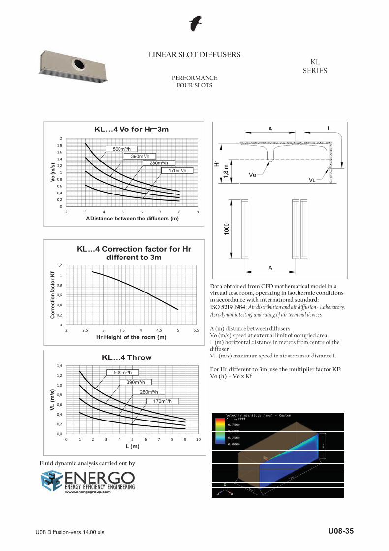
KL…4 Vo for Hr=3m
170m³/h280m³/h
390m³/h500m³/h
0 8
1
1,2
tor K
f
KL…4 Correction factor for Hr different to 3m
Fluid dynamic analysis carried out by
Data obtained from CFD mathematical model in a virtual test room, operating in isothermic conditions in accordance with international standard:ISO 5219 1984: Air distribution and air diffusion - Laboratory. Aerodynamic testing and rating of air terminal devices.
A (m) distance between diffusersVo (m/s) speed at external limit of occupied area L (m) horizontal distance in meters from centre of the diffuserVL (m/s) maximum speed in air stream at distance L
For Hr different to 3m, use the multiplier factor KF:Vo (h) = Vo x Kf
0
0,2
0,4
0,6
0,8
2 2,5 3 3,5 4 4,5 5 5,5
Cor
rect
ion
fact
Hr Height of the room (m)
0,0
0,2
0,4
0,6
0,8
1,0
1,2
1,4
0 1 2 3 4 5 6 7 8 9 10
VL (m
/s)
L (m)
KL…4 Throw
170m³/h
280m³/h
390m³/h
500m³/h
U08 Diffusion-vers.14.00.xls U08-35

LINEAR SLOT DIFFUSERSKL
SERIESPERFORMANCE
FOUR SLOTS
Data obtained from CFD mathematical model in a virtual test room operating in heating conditions with �T=10°C in accordance with international standard:ISO 5219 1984: Air distribution and air diffusion - Laboratory. Aerodynamic testing and rating of air terminal devices.H1 (m) vertical distance in meters from the centre of the diffuser where the inversion of the air flow occurs.
Data measured in reverberating room in accordance with the following international standards:ISO 3741 1999: Acoustic - determination of sound power l l f d
0
0,5
1
1,5
2
2,5
150 200 250 300 350 400 450 500 550
H1 (m
)
Q (m³/h)
KL…4 Vertical throw �T=10°C
50
60
KLV…4 Sound power
Lw Horizontal levels of noise sources using sound pressure - Precision methods for reverberation rooms
ISO 5135 1997: Acoustic - determination of sound power levels of noise from air-terminal devices ; air terminal units; dampers and valves by measurement in a reverberation room.
The data shown does not consider the attenuation given by the place of installation. This attenuation is normally included between 6 and 10dBa and is determined by the dimensions of the room, its shape and the arrangements of the furnishings within it.
0
10
20
30
40
50
150 200 250 300 350 400 450 500 550
Lw (d
Ba)
Q (m³/h)
throw
Lw Vertical throw
0
10
20
30
40
50
60
70
150 200 250 300 350 400 450 500 550
Lw (d
Ba)
Q (m³/h)
KLS…4 Sound power
Lw Horizontal throw
Lw Vertical throw
U08 Diffusion-vers.14.00.xls U08-36

LINEAR SLOT DIFFUSERSKL
SERIESPERFORMANCE
FOUR SLOTS
Data obtained from CFD mathematical model in a virtual test room, operating in isothermic conditions in accordance with international standard:ISO 5219 1984: Air distribution and air diffusion -Laboratory. Aerodynamic testing and rating of air terminal devices.
0
10
20
30
40
50
60
70
80
150 200 250 300 350 400 450 500 550
�p (P
a)
Q (m³/h)
KLV…4 Pressure drop
�P Horizontal throw
�P Vertical throw
60
70
80
KLS…4 Pressure drop
�P Horizontal throw
0
10
20
30
40
50
150 200 250 300 350 400 450 500 550
�p (P
a)
Q (m³/h)
�P Vertical throw
U08 Diffusion-vers.14.00.xls U08-37

LINEAR SLOT DIFFUSERS KLV KLS
SERIESASSEMBLY INSTRUCTIONS VERSION WITH FIXING SPRING
Vertically position the lug slot centrally or near the centre acting as shown in the picture, with a screwdriver at the ends of the deflector (without applying pressure to the centre of it).
Locate the spring attached inside the plenum (shown above in section).
Thread the hook shown in the picture through the slot with the deflector previously positioned vertically taking care to insert it on the side of the fixing hole shown.Number of springs: - 2 springs for diffuser, regardless of length
Using the hook stretch the spring and hook it to the fixing hole.Repeat on the other side.Release the diffuser that as a result of the tension in the springs will stay aligned with the plenum.
NOTE
For lengths up to 2000mm there are two springs already included in the product code of the diffuser.For lengths over 2000mm composed of several diffusers, two mounting springs for each unit should be foreseen.
U08 Diffusion-vers.14.00.xls U08-38

LINEAR SLOT DIFFUSERS KLV KLS
SERIESFITTING INSTRUCTIONS FOR VERSIONS WITH FIXING BRIDGE
Vertically position the lug of the central slot or near the centre acting as shown in the figure, with a screwdriver at the ends of the deflector (without applying pressure to the centre of it).
Attach fixing bridges to the diffuser by inserting the screw heads in its slots.Insert the diffuser into the plenum and, turning the screws, place the bridge on the folds of sheet metal cut into the sides of the plenum.
Number of bridges: - Up to 1500mm length; 2 bridges- Up to 1500mm length; 2 bridges - 1500mm length over: 3 bridges.
turn the screws until the diffuser completely touches the ceiling.
NOTEFor lengths up to 1500mm two bridges are already included in the code of the diffuser.For lengths over 1500mm up to 2000mm three bridges are already included in the code of the speaker.For lengths over 2000mm composed by various elements, it is necessary to foresee:2 fixing bridges for each element of length up to 1500mm;3 fixing bridges for each element of lengths greater than 1500mm.
U08 Diffusion-vers.14.00.xls U08-39
AR
0P
ABRZ
(*) the version without deflectors is best used for the return of air.
AR
0P
LINEAR SLOT DIFFUSERS KLV KLS
SERIESHOW TO ORDER
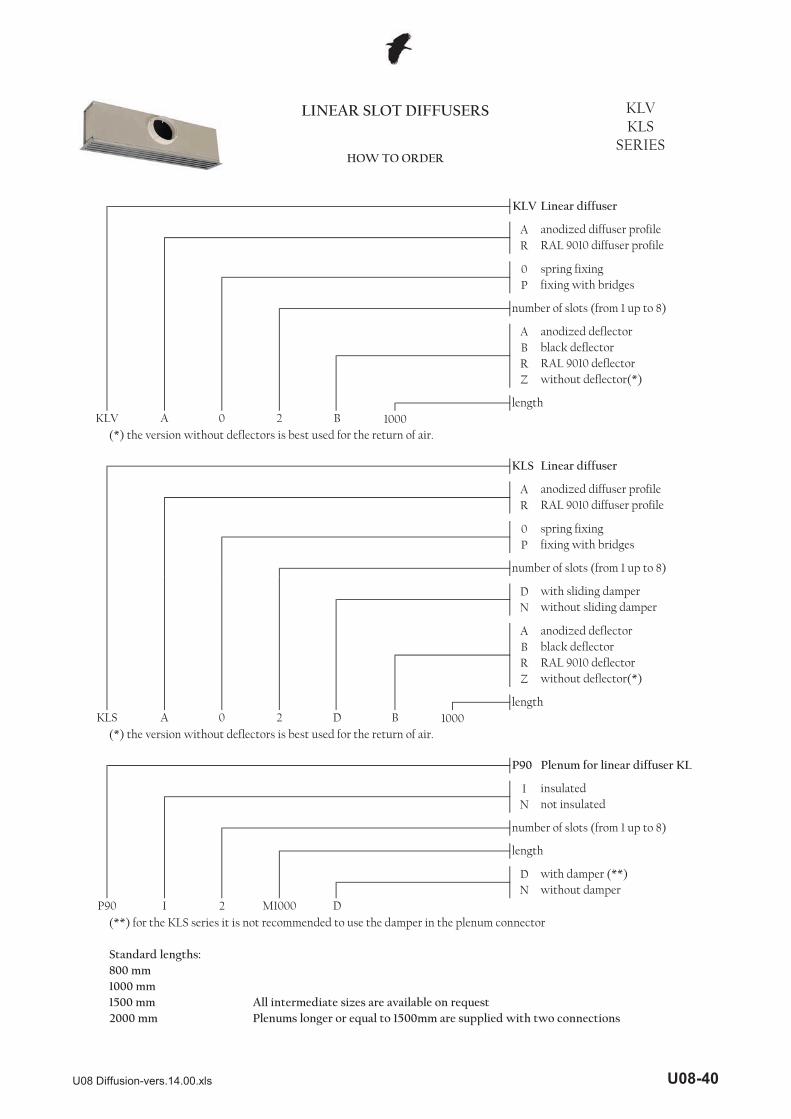
Linear diffuser
RAL 9010 diffuser profile
KLV
Linear diffuser
black deflectorRAL 9010 deflector without deflector(*)
spring fixingfixing with bridges
number of slots (from 1 up to 8)
anodized deflector
length KLV A 0 2 B 1000
RAL 9010 diffuser profile
spring fixing
number of slots (from 1 up to 8)
fixing with bridges
anodized diffuser profile
KLS
anodized diffuser profile
DN
ABRZ
(*) the version without deflectors is best used for the return of air.
IN
DN
(**) for the KLS series it is not recommended to use the damper in the plenum connector
1000 mm1500 mm All intermediate sizes are available on request2000 mm Plenums longer or equal to 1500mm are supplied with two connections
Standard lengths:800 mm
1000
anodized deflector
without deflector(*)RAL 9010 deflector black deflector
D
P90 Plenum for linear diffuser KL
lengthKLS A 0 2 B
insulatednot insulated
length
with damper (**)
with sliding damperwithout sliding damper
number of slots (from 1 up to 8)
P90 I 2 M1000 Dwithout damper
U08 Diffusion-vers.14.00.xls U08-40

HIGH AIR FLOW LINEAR SLOT DIFFUSERS KD
SERIESOVERVIEW
CHARACTERISTICS APPLICATIONS
OVERVIEW :The KD series linear diffusers allow to manage high air flows with minimum pressure losses and generated noise power.They allow to fully make us of the induction principle, guaranteeing optimum comfort conditions, no noticeable air currents and temperature uniformity, even in large areas by positioning the diffusers along the perimeter of the ceiling.
CHARACTERISTICS AND OPERATION :The KD series diffusers are constructed from an aluminium diffuser body housing the different exhaust slots and a series of deflector blades, also in aluminium, for the horizontal or vertical air though. The change of direction of the air through can be easily made without removing the diffuser but simply using a supplied tool. The regulation of the air flow can be made by using a butterfly type damper in the plenum connection.
APPLICATIONS : Th KD i diff id l i li i i h ili
DIFFUSER INSTALLATION: The KD series diffusers are installed inside special plenum boxes, by suspension using fixing bridges. This solution allows a quick installation even at the end of work carried out on the building site.
FINISH : The KDA and KDF diffusers are constructed from an aluminium body anodized or painted white RAL 9010 with a black painted deflection blade. The KDP diffusers are constructed from an aluminium body and a carbon steel panel painted RAL 9010 and a black painted deflector blade.Special finishes for the diffuser body can be made on requested.
The KD series diffusers are ideal in application with a ceiling height between 3 and 6 meters like open space offices, commercial galleries hospital wards or hotel rooms.
VERSIONSKDA : standard version for ventilation;KDF: version for supply and extraction with anti-dust filter, ideal for guaranteeing the cleaning of the air in recycle systems;KDP: version installed on steel panel, suitable for installation in modular counter ceilings, used for supply of air.
U08 Diffusion-vers.14.00.xls U08-41
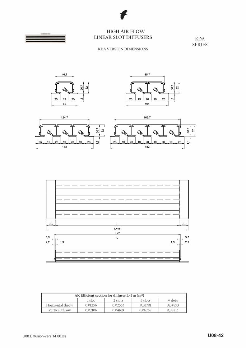
HIGH AIR FLOW HIGH AIR FLOW LINEAR SLOT DIFFUSERS KDA
SERIESKDA VERSION DIMENSIONS
AK Efficient section for diffuser L=1 m (m²)
Horizontal throw 0,01256 0,02553 0,03701 0,04853
( )1 slot 2 slots 3 slots 4 slots
Vertical throw 0,02106 0,04169 0,06262 0,08215
U08 Diffusion-vers.14.00.xls U08-42

HIGH AIR FLOW LINEAR SLOT DIFFUSERS KDF
SERIESKDF VERSION DIMENSIONS
Rounded edge Straight edge
2 F=3 F2 l 3 l 4 l l 104 5
AK Efficient section for diffuser L=1 m (m²) slots 66,53 F=4 F=
Vertical throw 0,04169 0,06262 0,08215
2 slots 3 slots 4 slots slots 104,5Horizontal throw 0,02553 0,03701 0,04853 slots 144,5
U08 Diffusion-vers.14.00.xls U08-43
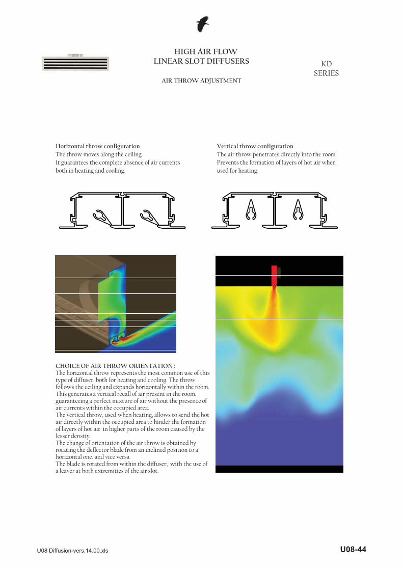
Horizontal throw configuration Vertical throw configurationThe throw moves along the ceiling The air throw penetrates directly into the roomIt guarantees the complete absence of air currents Prevents the formation of layers of hot air whenboth in heating and cooling. used for heating.
HIGH AIR FLOW LINEAR SLOT DIFFUSERS KD
SERIESAIR THROW ADJUSTMENT
CHOICE OF AIR THROW ORIENTATION :The horizontal throw represents the most common use of this type of diffuser, both for heating and cooling. The throw follows the ceiling and expands horizontally within the room. This generates a vertical recall of air present in the room, guaranteeing a perfect mixture of air without the presence of air currents within the occupied area.The vertical throw, used when heating, allows to send the hot air directly within the occupied area to hinder the formation of layers of hot air in higher parts of the room caused by the lesser density.The change of orientation of the air throw is obtained by rotating the deflector blade from an inclined position to a horizontal one, and vice versa. The blade is rotated from within the diffuser, with the use of a leaver at both extremities of the air slot.
U08 Diffusion-vers.14.00.xls U08-44

The adjustment of the air throw from horizontal to vertical position is made using the special lever suppliedfollowing the sequence here shown
From horizontal to vertical throw
HIGH AIR FLOW LINEAR SLOT DIFFUSERS KD
SERIESAIR THROW ADJUSTMENTS
From vertical to horizontal throw
U08 Diffusion-vers.14.00.xls U08-45
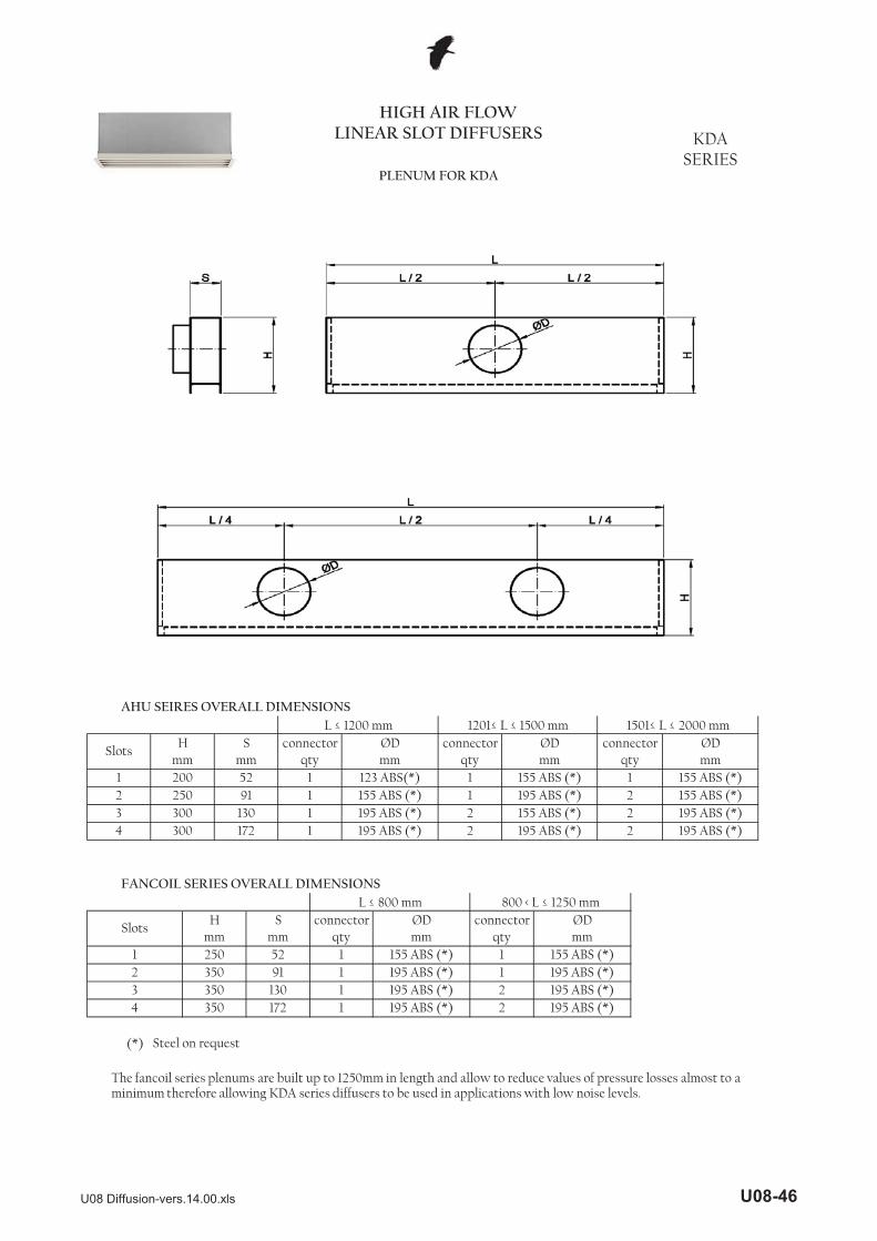
HIGH AIR FLOW LINEAR SLOT DIFFUSERS KDA
SERIESPLENUM FOR KDA
(*)
FANCOIL SERIES OVERALL DIMENSIONS
2
1
connectorqty
1mm
1 250
2 250 155 ABS (*) 1 2130 1 2
SlotsH ØD connector connector
mm qty qty
qty mm
AHU SEIRES OVERALL DIMENSIONSL � 1200 mm 1201� L � 1500 mm 1501� L � 2000 mm
S ØD ØDmm mm qty mm mm
connector
1 200 123 ABS(*) 1 155 ABS (*) 155 ABS (*)52 1 1195 ABS (*) 155 ABS (*)
3 300 195 ABS (*) 2 155 ABS (*) 195 ABS (*)91 1
4 300 195 ABS (*) 2 195 ABS (*) 195 ABS (*)172 1 2
L � 800 mm 800 < L � 1250 mm
SlotsH S connector ØD ØD
mm mm52 1 155 ABS (*) 155 ABS (*)
2 350 91 1 195 ABS (*) 195 ABS (*)
195 ABS (*)3 350 130 1 195 ABS (*) 195 ABS (*)2
Steel on request
4 350 172 1 195 ABS (*)
The fancoil series plenums are built up to 1250mm in length and allow to reduce values of pressure losses almost to a minimum therefore allowing KDA series diffusers to be used in applications with low noise levels.
U08 Diffusion-vers.14.00.xls U08-46

HIGH AIR FLOW LINEAR SLOT DIFFUSERS KDA
SERIESPLENUM FOR KDA
FITTING
To secure the KDA diffusers to the AHU and FANCOIL series plenums, strictly follow the fixing procedure shown below.
Position the deflectors for vertical throw and hook the fixing bridges provided
Insert the diffuser inside the plenum and place the bridges on the two blades inside the plenump
Tighten the bridge screws by inserting the screwdriver within the diffuser, thenposition the deflectors as required.
U08 Diffusion-vers.14.00.xls U08-47

2 250 98 1
L � 1200 mmFILTER HOLDER SERIES OVERALL DIMENSIONS
HIGH AIR FLOW LINEAR SLOT DIFFUSERS KDF
KDP SERIESPLENUM FOR KDF KDP
SlotsH S connection
mmØDmm
155 ABS (*)mm qty
(*)4 300 177 1
2 250 98 13 300 137 1
Steel on request
155 ABS ( )195 ABS (*)195 ABS (*)
The Filter Holder series plenums are built up to 1200mm in length and can be used both for the KDP, without panel, and KDP, with panel, diffusers.
U08 Diffusion-vers.14.00.xls U08-48

HIGH AIR FLOW LINEAR SLOT DIFFUSERS KDF
KDP SERIESPLENUM FOR KDF KDP
FITTING
To secure the KDF and KDP diffusers, strictly follow the fitting procedure shown below.
Open the diffuser by lifting and rotating the central section.
Insert the diffuser inside the plenum until the slots in the frame are aligned with the holes in the end caps of the plenum. Fix the diffuser using the screws supplied in the hole on the plenum end caps.
Insert the supplied filter blocking clamps in the grooves, insert the filter and fix in place with the supplied screws. Reclose the diffuser and, if necessary, adjust the deflectors in the chosen position.
U08 Diffusion-vers.14.00.xls U08-49

HIGH AIR FLOW LINEAR SLOT DIFFUSERS KD
SERIESONE SLOT
PERFORMANCE
Data obtained from CFD mathematical model in a
Fluid dynamic analysis carried out by
Data obtained from CFD mathematical model in a virtual test room, operating in isothermic conditions in accordance with international standard:ISO 5219 1984: Air distribution and air diffusion -Laboratory. Aerodynamic testing and rating of air terminal devices.
A (m) distance between diffusersVo (m/s) speed at limit of occupied area L (m) horizontal distance in meters from the centre of diffuserVL (m/s) maximum speed in air stream at distance L
For Hr different to 3m, use the multiplier factor KF:Vo (h) = Vo x Kf
U08 Diffusion-vers.14.00.xls U08-50

HIGH AIR FLOW LINEAR SLOT DIFFUSERS KD
SERIESONE SLOT
PERFORMANCE
Data measured in reverberating room in accordance with the following international standards:ISO 3741 1999: Acoustic - determination of sound power levels of noise sources using sound pressure - Precision methods for
Data obtained from CFD mathematical model in a virtual test room operating in heating conditions with �T=10°C in accordance with international standard:ISO 5219 1984: Air distribution and air diffusion - Laboratory. Aerodynamic testing and rating of air terminal devices.H1 (m) vertical distance in meters from the centre of the diffuser where the inversion of the air flow occurs.
With AHU plenum or Filterholder plenum
With FANCOIL plenum
f g p freverberation rooms
ISO 5135 1997: Acoustic - determination of sound power levels of noise from air-terminal devices ; air terminal units; dampers and valves by measurement in a reverberation room.
The data shown does not consider the attenuation given by the place of installation. This attenuation is normally included between 6 and 10dBa and is determined by the dimensions of the room, its shape and the arrangements of the furnishings within it.
U08 Diffusion-vers.14.00.xls U08-51

HIGH AIR FLOW LINEAR SLOT DIFFUSERS KD
SERIESONE SLOT
PERFORMANCE
With AHU series plenum
Data obtained from CFD mathematical model in a virtual test room, operating in isothermic conditions in accordance with international standard:ISO 5219 1984: Air distribution and air diffusion -Laboratory. Aerodynamic testing and rating of air terminal devices.
With FANCOIL series plenum
U08 Diffusion-vers.14.00.xls U08-52
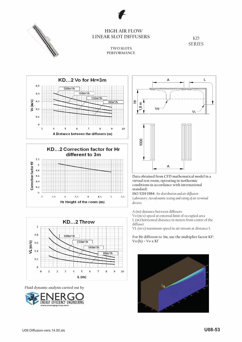
HIGH AIR FLOW LINEAR SLOT DIFFUSERS KD
SERIESTWO SLOTS
PERFORMANCE
Data obtained from CFD mathematical model in a
Fluid dynamic analysis carried out by
Data obtained from CFD mathematical model in a virtual test room, operating in isothermic conditions in accordance with international standard:ISO 5219 1984: Air distribution and air diffusion -Laboratory. Aerodynamic testing and rating of air terminal devices.
A (m) distance between diffusersVo (m/s) speed at external limit of occupied area L (m) horizontal distance in meters from centre of the diffuserVL (m/s) maximum speed in air stream at distance L
For Hr different to 3m, use the multiplier factor KF:Vo (h) = Vo x Kf
U08 Diffusion-vers.14.00.xls U08-53

HIGH AIR FLOW LINEAR SLOT DIFFUSERS KD
SERIESTWO SLOTS
PERFORMANCE
Data measured in reverberating room in accordance with the following international standards:ISO 3741 1999: Acoustic - determination of sound power levels of noise sources using sound pressure - Precision methods for
Data obtained from CFD mathematical model in a virtual test room operating in heating conditions with �T=10°C in accordance with international standard:ISO 5219 1984: Air distribution and air diffusion - Laboratory. Aerodynamic testing and rating of air terminal devices.H1 (m) vertical distance in meters from the centre of the diffuser where the inversion of the air flow occurs.
With AHU plenum or Filterholder plenum
With FANCOIL plenum
f g p freverberation rooms
ISO 5135 1997: Acoustic - determination of sound power levels of noise from air-terminal devices ; air terminal units; dampers and valves by measurement in a reverberation room.
The data shown does not consider the attenuation given by the place of installation. This attenuation is normally included between 6 and 10dBa and is determined by the dimensions of the room, its shape and the arrangements of the furnishings within it.
U08 Diffusion-vers.14.00.xls U08-54
HIGH AIR FLOW LINEAR SLOT DIFFUSERS KD
SERIESTWO SLOTS
PERFORMANCE
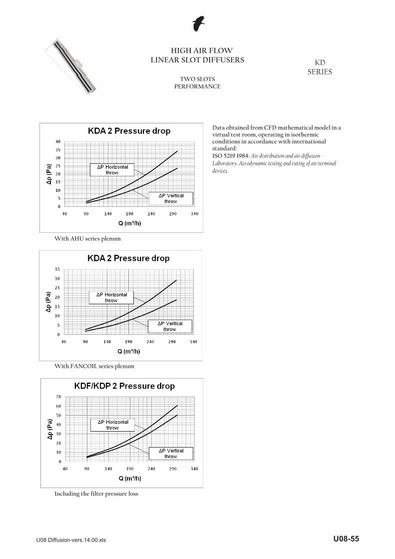
With AHU series plenum
Data obtained from CFD mathematical model in a virtual test room, operating in isothermic conditions in accordance with international standard:ISO 5219 1984: Air distribution and air diffusion -Laboratory. Aerodynamic testing and rating of air terminal devices.
With FANCOIL series plenum
Including the filter pressure loss
U08 Diffusion-vers.14.00.xls U08-55

HIGH AIR FLOW LINEAR SLOT DIFFUSERS KD
SERIESTHREE SLOTS
PERFORMANCE
Data obtained from CFD mathematical model in a
Fluid dynamic analysis carried out by
Data obtained from CFD mathematical model in a virtual test room, operating in isothermic conditions in accordance with international standard:ISO 5219 1984: Air distribution and air diffusion -Laboratory. Aerodynamic testing and rating of air terminal devices.
A (m) distance between diffusersVo (m/s) speed at external limit of occupied area L (m) horizontal distance in meters from centre of the diffuserVL (m/s) maximum speed in air stream at distance L
For Hr different to 3m, use the multiplier factor KF:Vo (h) = Vo x Kf
U08 Diffusion-vers.14.00.xls U08-56

HIGH AIR FLOW LINEAR SLOT DIFFUSERS KD
SERIESTHREE SLOTS
PERFORMANCE
Data measured in reverberating room in accordance with the following international standards:ISO 3741 1999: Acoustic - determination of sound power levels of noise sources using sound pressure - Precision methods for
Data obtained from CFD mathematical model in a virtual test room operating in heating conditions with �T=10°C in accordance with international standard:ISO 5219 1984: Air distribution and air diffusion - Laboratory. Aerodynamic testing and rating of air terminal devices.H1 (m) vertical distance in meters from the centre of the diffuser where the inversion of the air flow occurs.
With AHU plenum or Filterholder plenum
With FANCOIL plenum
f g p freverberation rooms
ISO 5135 1997: Acoustic - determination of sound power levels of noise from air-terminal devices ; air terminal units; dampers and valves by measurement in a reverberation room.
The data shown does not consider the attenuation given by the place of installation. This attenuation is normally included between 6 and 10dBa and is determined by the dimensions of the room, its shape and the arrangements of the furnishings within it.
U08 Diffusion-vers.14.00.xls U08-57

HIGH AIR FLOW LINEAR SLOT DIFFUSERS KD
SERIESTHREE SLOTS
PERFORMANCE
With AHU series plenum
Data obtained from CFD mathematical model in a virtual test room, operating in isothermic conditions in accordance with international standard:ISO 5219 1984: Air distribution and air diffusion -Laboratory. Aerodynamic testing and rating of air terminal devices.
With FANCOIL series plenum
Including the filter pressure loss
U08 Diffusion-vers.14.00.xls U08-58

HIGH AIR FLOW LINEAR SLOT DIFFUSERS KD
SERIESFOUR SLOTS
PERFORMANCE
Data obtained from CFD mathematical model in a
Fluid dynamic analysis carried out by
Data obtained from CFD mathematical model in a virtual test room, operating in isothermic conditions in accordance with international standard:ISO 5219 1984: Air distribution and air diffusion -Laboratory. Aerodynamic testing and rating of air terminal devices.
A (m) distance between diffusersVo (m/s) speed at external limit of occupied area L (m) horizontal distance in meters from centre of the diffuserVL (m/s) maximum speed in air stream at distance L
For Hr different to 3m, use the multiplier factor KF:Vo (h) = Vo x Kf
U08 Diffusion-vers.14.00.xls U08-59

HIGH AIR FLOW HIGH AIR FLOW LINEAR SLOT DIFFUSERS KD
SERIESFOUR SLOTS
PERFORMANCE
Data obtained from CFD mathematical model in a virtual test room operating in heating conditions with �T=10°C in accordance with international standard:
d b d d ff bISO 5219 1984: Air distribution and air diffusion - Laboratory. Aerodynamic testing and rating of air terminal devices.H1 ( ) ti l di t i t f th t f thH1 (m) vertical distance in meters from the centre of the diffuser where the inversion of the air flow occurs.
Data measured in reverberating room in accordance with the following international standards:ISO 3741 1999: Acoustic - determination of sound power levels of noise sources using sound pressure - Precision methods for reverberation rooms
ISO 5135 1997 A i d i i f d l lISO 5135 1997: Acoustic - determination of sound power levels of noise from air-terminal devices ; air terminal units; dampers and valves by measurement in a reverberation roomvalves by measurement in a reverberation room.
The data shown does not consider the attenuation givenThe data shown does not consider the attenuation given by the place of installation. This attenuation is normally included between 6 and 10dBa and is determined by the ydimensions of the room, its shape and the arrangements of the furnishings within it.
With AHU plenum or Filterholder plenum
With FANCOIL plenum
U08 Diffusion-vers.14.00.xls U08-60

HIGH AIR FLOW LINEAR SLOT DIFFUSERS KD
SERIESFOUR SLOTS
PERFORMANCE
With AHU series plenum
Data obtained from CFD mathematical model in a virtual test room, operating in isothermic conditions in accordance with international standard:ISO 5219 1984: Air distribution and air diffusion -Laboratory. Aerodynamic testing and rating of air terminal devices.
With FANCOIL series plenum
Including the filter pressure loss
U08 Diffusion-vers.14.00.xls U08-61
AR
01
ABRZ
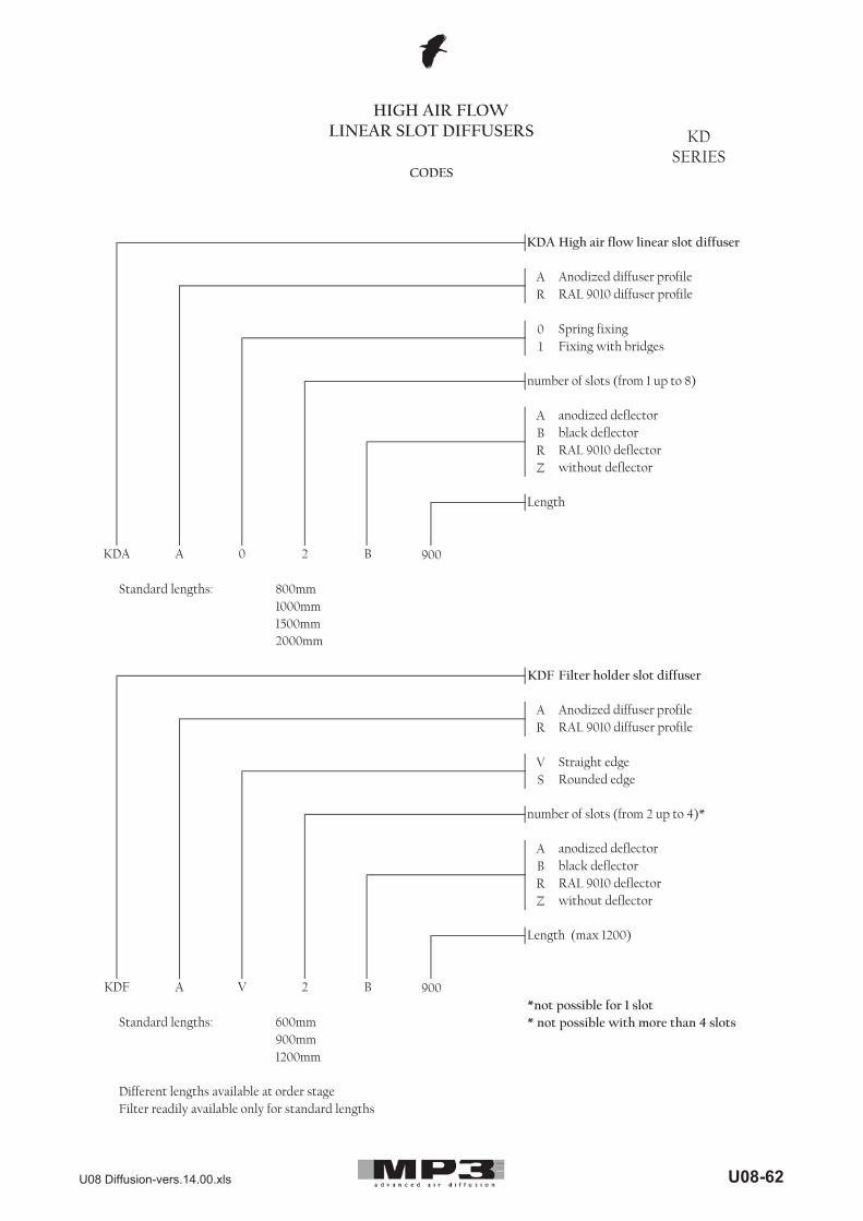
Standard lengths: 800mm1000mm1500mm
AR
VS
ABRZ
*not possible for 1 slotStandard lengths: 600mm * not possible with more than 4 slots
900mm1200mm
black deflectorRAL 9010 deflector
Different lengths available at order stageFilter readily available only for standard lengths
without deflector
KDF A
Length (max 1200)
V 2 B 900
number of slots (from 2 up to 4)*
anodized deflector
2000mm
Filter holder slot diffuser
Anodized diffuser profileRAL 9010 diffuser profile
Straight edgeRounded edge
KDA A 0 2 B 900
KDF
number of slots (from 1 up to 8)
anodized deflectorblack deflectorRAL 9010 deflector without deflector
Length
RAL 9010 diffuser profile
Spring fixingFixing with bridges
HIGH AIR FLOW LINEAR SLOT DIFFUSERS KD
SERIESCODES
High air flow linear slot diffuser
Anodized diffuser profile
KDA
U08 Diffusion-vers.14.00.xls U08-62

R
Z
*not possible for 1 slotStandard lengths: * not possible with more than 4 slots
=
===
filter for KDP diffuser, 3 slots L=900
FP3870105
EXAMPLE
Length: 900-30= 870Width: 105mmCode:
Filter length Diffuser length -30mm
Filter width 70mm 2 slot diffuser105mm 3 slot diffuser145mm 4 slot diffuser
G2 filter 3mm thickness
Length
Width
FP3 870 105
FP3
600mm900mm1000mm
Standard panel 1200x300mmDifferent lengths and panels agreeable at order stageFilter readily available only for standard lengths
Length of diffuser
KDP R 2 B 900
RAL 9010 deflectorblack deflector
R
Bwithout deflector
number of slots (from 2 up to 4)*
HIGH AIR FLOW LINEAR SLOT DIFFUSERS KD
SERIESCODES
Filter holder linear diffuser with panelKDP
RAL 9010 diffuser profile
U08 Diffusion-vers.14.00.xls U08-63

12
I
N
NDMF
I
N
NDMF
*not possible with 1 slot* not possible with more than 4 slots
P93 I 3 600 D
Connectors in steel without damperConnectors in steel with perforated damper
No insulation
Length (max 1200)
C
Connectors in ABS without damperConnectors in ABS with flat damper
number of slots (from 2 up to 4)*
External insulation
P93
Internal insulation
Plenum for linear diffuser KDF and KDP
Connectors in steel without
P9 I 3 600 D
Connectors in steel with perforated damper
1
Internal insulationNo insulation
C
Length
Connectors in ABS with flat Connectors in ABS without damper
number of slots (from 1 up to 8)
HIGH AIR FLOW LINEAR SLOT DIFFUSERS KD
SERIESCODES
External insulation
UTA seriesFANCOIL series
P9 Plenum for linear diffuser KDA
U08 Diffusion-vers.14.00.xls U08-64

Horizontal throw configurationThe air flows along the ceilingGuarantees the complete absence of air currentsboth in heating and cooling.
LINEAR SLOT DIFFUSERSKH
SERIESOVERVIEW
CHARACTERISTICS APPLICATIONS
OVERVIEW :The KH series linear diffusers allow to manage high air flows with minimum pressure losses and generated noise power.They allow to fully make use of the induction principle, guaranteeing optimum comfort conditions, no noticeable air currents and temperature uniformity, even in large spaces by positioning the diffusers along the perimeter of the ceiling.
CHARACTERISTICS AND FUNCTION:The KH series diffusers are constructed from an aluminium body housing the different exhaust slots each with a pair of deflector blades. The change of direction of the air throw can be easily made without removing the diffuser. The regulation of the air flow can be made by using a butterfly type damper in the plenum connection.
APPLICATIONS :The KH diffusers are ideal in air ventilations applications with ceiling heights from 2,4 to 4 metres.
A A
Vertical throw configurationThe air penetrates directly into the roomPrevents the formation of layers of hot air when used for heating.
DIFFUSER INSTALLATION: The KH diffusers are installed inside special plenums fixed on the sides with screws or by suspension by using mounting bridges. This second solution allows for a quick installation even after all the work has been completed in the building site. The wider shape of the plenum allows to contain the generated noise and the pressure losses connected to the expanding effect of the air.
FINISH : The KH diffusers are constructed from an aluminium or RAL 9010 painted body and deflector blades.Different finishes can be agreed on request.
U08 Diffusion-vers.14.00.xls U08-65

LINEAR SLOT DIFFUSERSKH
SERIESDIMENTIONS
Efficient section AK for diffuser L=1 m (m²)( )1 slot 2 slots 3 slots 4 slots 5 slots0,012 0,025 0,037 0,052 0,069
U08 Diffusion-vers.14.00.xls U08-66

(*)
LINEAR SLOT DIFFUSERSKH
SERIESPLENUM
N° slots B H Lb1 40 200 123 ABS (*)2 71 200 123 ABS (*)3 101,5 235 155 ABS (*)4 132 235 155 ABS (*)
for L up to 1500 one connection ØNfor L greater than 1500: two connections ØN
5 163 275 195 ABS (*)
Steel on request
5080,6111,2141,8172,4
ØN
( )
Corner connection
Mounting bridge
Steel on request
U08 Diffusion-vers.14.00.xls U08-67

LINEAR SLOT DIFFUSERSKH
SERIESPERFORMANCE
ONE SLOT
KH ... 1 Horizontal throw
KH ... 1 Vertical throw
Aeraulic data measured in isothermic conditions for a one meter long diffuser in accordance with the international standard:ISO 5219 1984: Air distribution and air diffusion - Laboratory. Aerodynamic testing and rating of air terminal devices.
L (m) horizontal distance in meters from the centre of the diffuserVL (m/s) maximum air speed in the air vain at a distance L H (m) distance from ceilingVh (m/s) speed at height H
Acoustic data measured in reverberating room for a one meter long diffuser in accordance with the international standard:ISO 3741 1999: Acoustic - determination of sound power levels of noise sources using sound pressure - Precision methods for reverberation rooms
ISO 5135 1997: Acoustic - determination of sound power levels of noise from air-terminal devices ; air terminal units; dampers and valves by measurement in a reverberation room.
The data shown does not consider the attenuation given by the place of installation. This attenuation is normally included between 6 and 10dBa and is determined by the dimensions of the room, its shape and the arrangements of the furnishings within it.
KH ... 1 Pressure drop
KH ... 1 Sound power
U08 Diffusion-vers.14.00.xls U08-68

LINEAR SLOT DIFFUSERSKH
SERIESPERFORMANCE
TWO SLOTS
KH ... 2 Horizontal throw
KH ... 2 Vertical throw
Aeraulic data measured in isothermic conditions for a one meter long diffuser in accordance with the international standard:ISO 5219 1984: Air distribution and air diffusion - Laboratory. Aerodynamic testing and rating of air terminal devices.
L (m) horizontal distance in meters from the centre of the diffuserVL (m/s) maximum air speed in the air vain at a distance L H (m) distance from ceilingVh (m/s) speed at height H
Acoustic data measured in reverberating room for a one meter long diffuser in accordance with the international standard:ISO 3741 1999: Acoustic - determination of sound power levels of noise sources using sound pressure - Precision methods for reverberation rooms
ISO 5135 1997: Acoustic - determination of sound power levels of noise from air-terminal devices ; air terminal units; dampers and valves by measurement in a reverberation room.
The data shown does not consider the attenuation given by the place of installation. This attenuation is normally included between 6 and 10dBa and is determined by the dimensions of the room, its shape and the arrangements of the furnishings within it.
KH ... 2 Pressure drop
KH ... 2 Sound power
U08 Diffusion-vers.14.00.xls U08-69
LINEAR SLOT DIFFUSERSKH
SERIESPERFORMANCE
THREE SLOTS
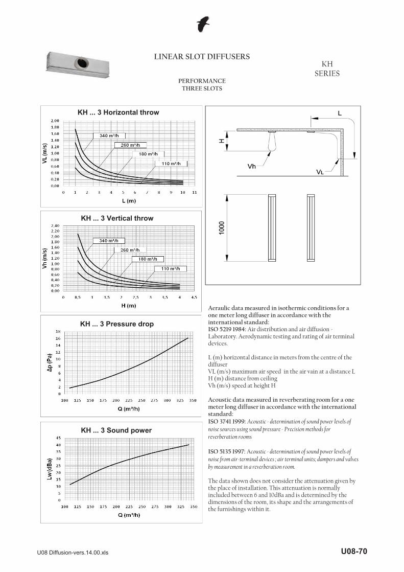
KH ... 3 Horizontal throw
KH ... 3 Vertical throw
Aeraulic data measured in isothermic conditions for a one meter long diffuser in accordance with the international standard:ISO 5219 1984: Air distribution and air diffusion -Laboratory. Aerodynamic testing and rating of air terminal devices.
L (m) horizontal distance in meters from the centre of the diffuserVL (m/s) maximum air speed in the air vain at a distance L H (m) distance from ceilingVh (m/s) speed at height H
Acoustic data measured in reverberating room for a one meter long diffuser in accordance with the international standard:ISO 3741 1999: Acoustic - determination of sound power levels of noise sources using sound pressure - Precision methods for reverberation rooms
ISO 5135 1997: Acoustic - determination of sound power levels of noise from air-terminal devices ; air terminal units; dampers and valves by measurement in a reverberation room.
The data shown does not consider the attenuation given by the place of installation. This attenuation is normally included between 6 and 10dBa and is determined by the dimensions of the room, its shape and the arrangements of the furnishings within it.
KH ... 3 Pressure drop
KH ... 3 Sound power
U08 Diffusion-vers.14.00.xls U08-70

LINEAR SLOT DIFFUSERSKH
SERIESPERFORMANCE
FOUR SLOTS
KH ... 4 Horizontal throw
KH ... 4 Vertical throw
Aeraulic data measured in isothermic conditions for a one meter long diffuser in accordance with the international standard:ISO 5219 1984: Air distribution and air diffusion - Laboratory. Aerodynamic testing and rating of air terminal devices.
L (m) horizontal distance in meters from the centre of the diffuserVL (m/s) maximum air speed in the air vain at a distance L H (m) distance from ceilingVh (m/s) speed at height H
Acoustic data measured in reverberating room for a one meter long diffuser in accordance with the international standard:ISO 3741 1999: Acoustic - determination of sound power levels of noise sources using sound pressure - Precision methods for reverberation rooms
ISO 5135 1997: Acoustic - determination of sound power levels of noise from air-terminal devices ; air terminal units; dampers and valves by measurement in a reverberation room.
The data shown does not consider the attenuation given by the place of installation. This attenuation is normally included between 6 and 10dBa and is determined by the dimensions of the room, its shape and the arrangements of the furnishings within it.
KH ... 4 Pressure drop
KH ... 4 Sound power
U08 Diffusion-vers.14.00.xls U08-71
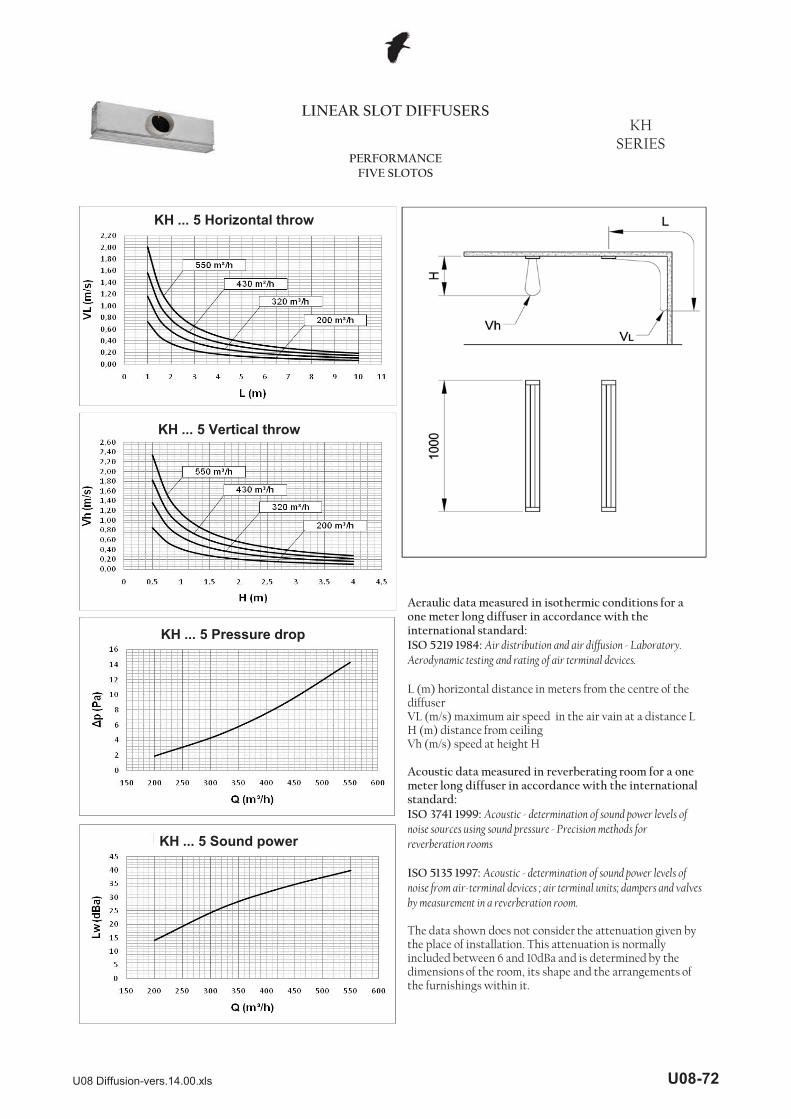
LINEAR SLOT DIFFUSERSKH
SERIESPERFORMANCE
FIVE SLOTOS
KH ... 5 Horizontal throw
KH ... 5 Vertical throw
Aeraulic data measured in isothermic conditions for a one meter long diffuser in accordance with the international standard:ISO 5219 1984: Air distribution and air diffusion - Laboratory. Aerodynamic testing and rating of air terminal devices.
L (m) horizontal distance in meters from the centre of the diffuserVL (m/s) maximum air speed in the air vain at a distance L H (m) distance from ceilingVh (m/s) speed at height H
Acoustic data measured in reverberating room for a one meter long diffuser in accordance with the international standard:ISO 3741 1999: Acoustic - determination of sound power levels of noise sources using sound pressure - Precision methods for reverberation rooms
ISO 5135 1997: Acoustic - determination of sound power levels of noise from air-terminal devices ; air terminal units; dampers and valves by measurement in a reverberation room.
The data shown does not consider the attenuation given by the place of installation. This attenuation is normally included between 6 and 10dBa and is determined by the dimensions of the room, its shape and the arrangements of the furnishings within it.
KH ... 5 Pressure drop
KH ... 5 Sound power
U08 Diffusion-vers.14.00.xls U08-72
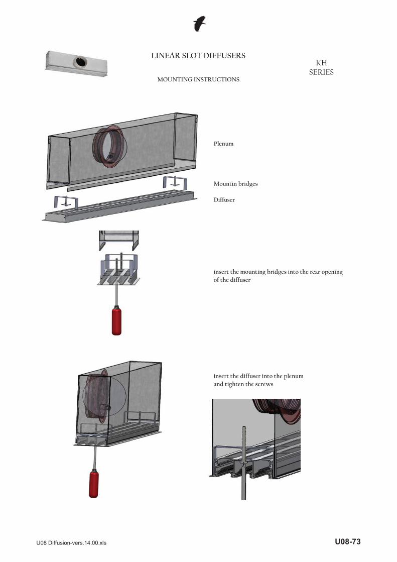
insert the mounting bridges into the rear openingof the diffuser
Diffuser
LINEAR SLOT DIFFUSERSKH
SERIESMOUNTING INSTRUCTIONS
Plenum
Mountin bridges
insert the diffuser into the plenumand tighten the screws
U08 Diffusion-vers.14.00.xls U08-73

CE
-----
N
-----R
* No special version are foreseenwith a greater number of slots
2
RAL9010 profile
RKH C N
deflectors RAL 9010deflectors RAL 9005
Number of slots (from 1 up to 5)*
Length
Anodized profile
LINEAR SLOT DIFFUSERSKH
SERIESORDER CODES
1000
KH Linear diffuser
With deflectors (supply)Without deflectors (extraction)
anodized deflectorsR
6
8
ND
Standard lengths: 600 mm800mm1000mm1200mm1500mm2000mm
Not insulated
Number of slots (from 1 up to 5)*
Length
Without damperWith damper
P8 7 2 1000 D
P8 Plenum for KH diffuser
Internal insulated7 External insulated
U08 Diffusion-vers.14.00.xls U08-74