linear static analysis of a simply-supported trussthe structure is comprised of truss segments...
TRANSCRIPT
MSC/NASTRAN 101 Exercise Workbook1-1
WORKSHOP PROBLEM 1
Linear Static Analysis of aSimply-Supported Truss
Objectives:
■ Create a MSC/NASTRAN input file directly or by usingMSC/PATRAN.
■ Run the analysis using MSC/NASTRAN.
■ Review results.

1-2 MSC/NASTRAN 101 Exercise Workbook
WORKSHOP 1 Simply Supported Truss
cha
t
MSC/NASTRAN 101 Exercise Workbook1-3
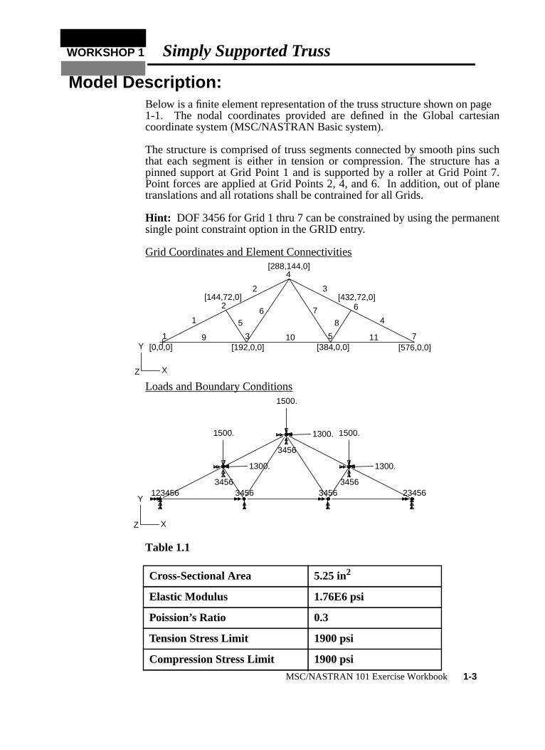
Model Description:Below is a finite element representation of the truss structure shown on page1-1. The nodal coordinates provided are defined in the Global cartesiancoordinate system (MSC/NASTRAN Basic system).
The structure is comprised of truss segments connected by smooth pins suthat each segment is either in tension or compression. The structure haspinned support at Grid Point 1 and is supported by a roller at Grid Point 7.Point forces are applied at Grid Points 2, 4, and 6. In addition, out of planetranslations and all rotations shall be contrained for all Grids.
Hint: DOF 3456 for Grid 1 thru 7 can be constrained by using the permanensingle point constraint option in the GRID entry.
Grid Coordinates and Element Connectivities
Loads and Boundary Conditions
Table 1.1
Cross-Sectional Area 5.25 in2
Elastic Modulus 1.76E6 psi
Poission’s Ratio 0.3
Tension Stress Limit 1900 psi
Compression Stress Limit 1900 psi
X
Y
Z
1
2
3
4
5
6
7
1
2 3
456 7
8
9 10 11
X
Y
Z
[0,0,0]
[144,72,0]
[288,144,0]
[192,0,0] [384,0,0]
[432,72,0]
[576,0,0]
XYZ
123456 3456
1500.
3456
3456
1500.
3456 3456
1500.
23456
X
Y
Z
1300.
1300.
1300.

Suggested Exercise Steps:
■ Generate a finite element representation of the truss structure using(GRID) and (CROD) elements.(Hint: Remember to use permanent constraints for DOF 3456.)
■ Define material (MAT1) and element (PROD) properties.
■ Apply simply-supported boundary constraints (SPC1) and pointforces (FORCE).
■ Use the load and boundary condition sets to define a loadcase(SUBCASE).
■ Prepare the model for a linear static analysis (SOL 101).
■ Submit it for a linear static analysis.
■ Review results.
1-4 MSC/NASTRAN 101 Exercise Workbook

WORKSHOP 1 Simply Supported Truss
MSC/NASTRAN 101 Exercise Workbook1-5
ID SEMINAR,PROB1______________________________________________________________________________________________________________________________________________________________________________________________________________________________________________________________________________________________________________________________________________________________________________________________________________________________________________________________________________CEND________________________________________________________________________________________________________________________________________________________________________________________________________________________________________________________________________________________________________________________________________________________________________________________________________________________________________________________________________________________________________________________________________________________________________________________________________________________________________________________________________________________________________________________________________________________________________________________________________________________________________________________________________________________________________________________________________________________________________________________________________________________________________________________________________________________________________________________________________________________________________________________________________________________________________________________________________________________________________________________________________________________________________________________________________________________________________________________________________________________________________________________________________________________________________________________________________________________________________________________________________________________BEGIN BULK

0
1 2 3 4 5 6 7 8 9 11-6 MSC/NASTRAN 101 Exercise Workbook

WORKSHOP 1 Simply Supported Truss
1 2 3 4 5 6 7 8 9 10
ENDDATA
MSC/NASTRAN 101 Exercise Workbook1-7
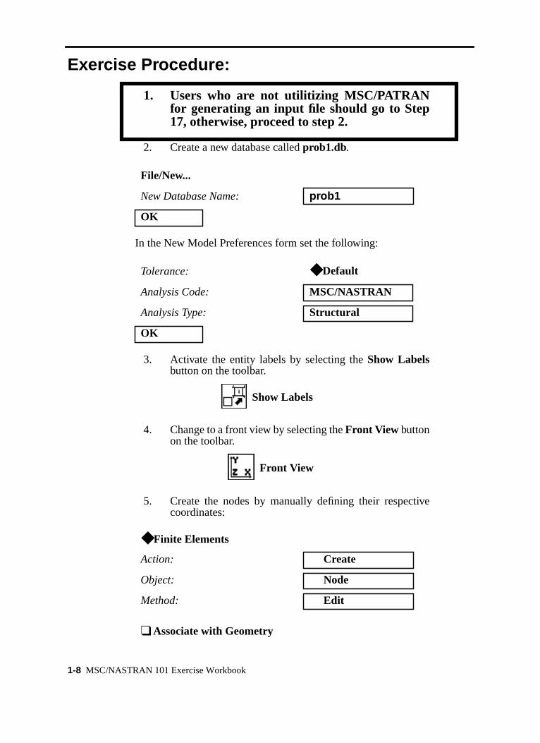
Exercise Procedure:
1. Users who are not utilitizing MSC/PATRANfor generating an input file should go to Step17, otherwise, proceed to step 2.
2. Create a new database calledprob1.db.
In the New Model Preferences form set the following:
3. Activate the entity labels by selecting theShow Labelsbutton on the toolbar.
4. Change to a front view by selecting theFront View buttonon the toolbar.
5. Create the nodes by manually defining their respectivecoordinates:
File/New...
New Database Name: prob1
OK
Tolerance: ◆ Default
Analysis Code: MSC/NASTRAN
Analysis Type: Structural
OK
◆ Finite Elements
Action: Create
Object: Node
Method: Edit
❑ Associate with Geometry
Show Labels
Front View
1-8 MSC/NASTRAN 101 Exercise Workbook

WORKSHOP 1 Simply Supported Truss
o
-
Repeat the previous operation to create the remaining nodes. Refer tthe figure on page 1-3 for the nodal coordinates.
Next, manually define the truss segment connectivities with BAR2 ele-ments using our newly created nodes. Again, refer to page 1-3 for connectivity information.
Node Location List: [0, 0, 0]
Apply
Node Location List: [144, 72, 0]
Apply
Node Location List: [192, 0, 0]
Apply
Node Location List: [288, 144, 0]
Apply
Node Location List: [384, 0, 0]
Apply
Node Location List: [432, 72, 0]
Apply
Node Location List: [576, 0, 0]
Apply
◆ Finite Elements
Action: Create
Object: Element
Method: Edit
Shape: Bar
MSC/NASTRAN 101 Exercise Workbook1-9

e-
Repeat the previous operation until all the truss segments have been crated.Topology: Bar2
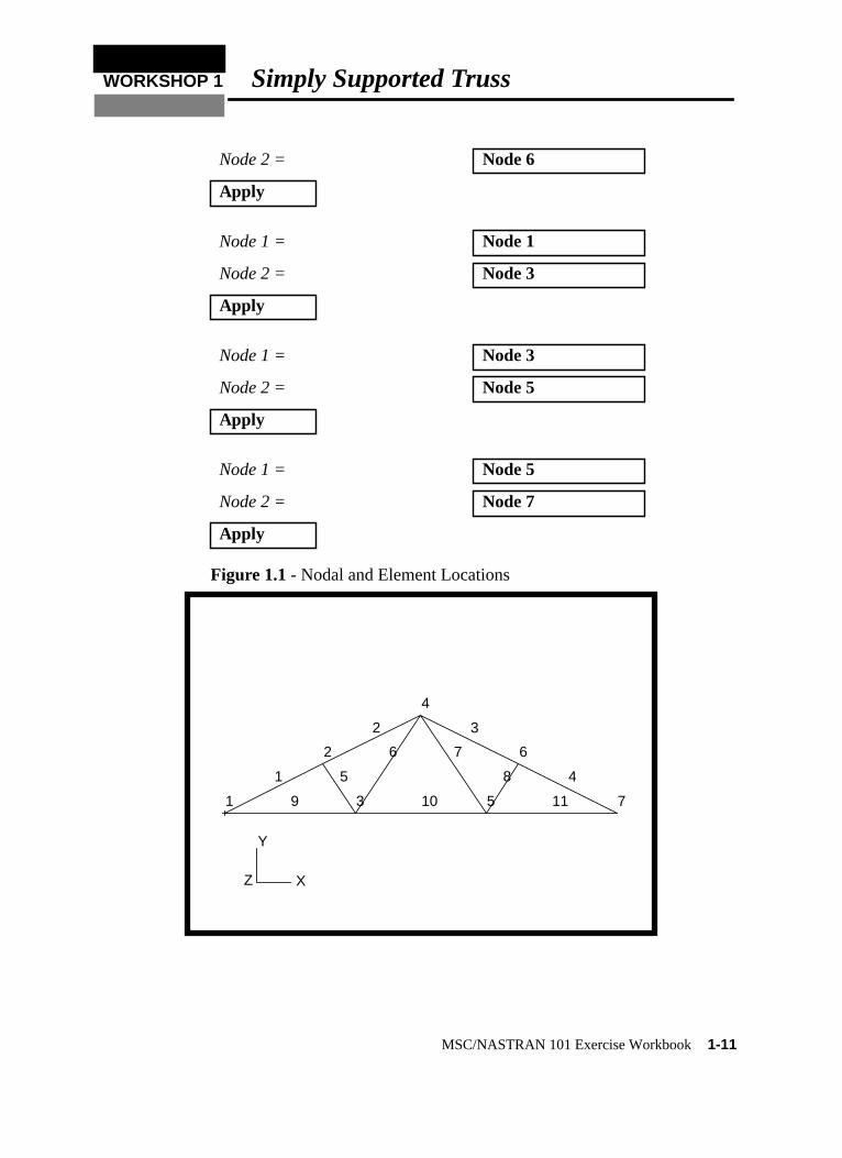
Node 1 = Node 1
Node 2 = Node 2
Apply
Node 1 = Node 2
Node 2 = Node 4
Apply
Node 1 = Node 4
Node 2 = Node 6
Apply
Node 1 = Node 6
Node 2 = Node 7
Apply
Node 1 = Node 2
Node 2 = Node 3
Apply
Node 1 = Node 3
Node 2 = Node 4
Apply
Node 1 = Node 4
Node 2 = Node 5
Apply
Node 1 = Node 5
1-10 MSC/NASTRAN 101 Exercise Workbook
WORKSHOP 1 Simply Supported Truss
Figure 1.1 - Nodal and Element Locations
Node 2 = Node 6
Apply
Node 1 = Node 1
Node 2 = Node 3
Apply
Node 1 = Node 3
Node 2 = Node 5
Apply
Node 1 = Node 5
Node 2 = Node 7
Apply
Y
Z
1
2
3
4
5
6
7
1
2 3
45
6 7
8
9 10 11
X
MSC/NASTRAN 101 Exercise Workbook1-11
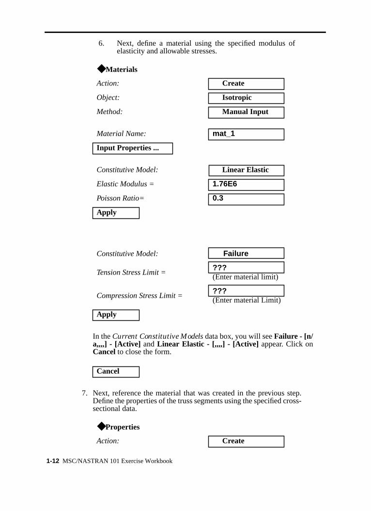
6. Next, define a material using the specified modulus ofelasticity and allowable stresses.
In theCurrent Constitutive Models data box, you will seeFailure - [n/a,,,,] - [Active] andLinear Elastic - [,,,,] - [Active] appear. Click onCancel to close the form.
7. Next, reference the material that was created in the previous step.Define the properties of the truss segments using the specified cross-sectional data.
◆ Materials
Action: Create
Object: Isotropic
Method: Manual Input
Material Name: mat_1
Input Properties ...
Constitutive Model: Linear Elastic
Elastic Modulus = 1.76E6
Poisson Ratio= 0.3
Apply
Constitutive Model: Failure
Tension Stress Limit =???(Enter material limit)
Compression Stress Limit =???(Enter material Limit)
Apply
Cancel
◆ Properties
Action: Create
1-12 MSC/NASTRAN 101 Exercise Workbook
WORKSHOP 1 Simply Supported Truss
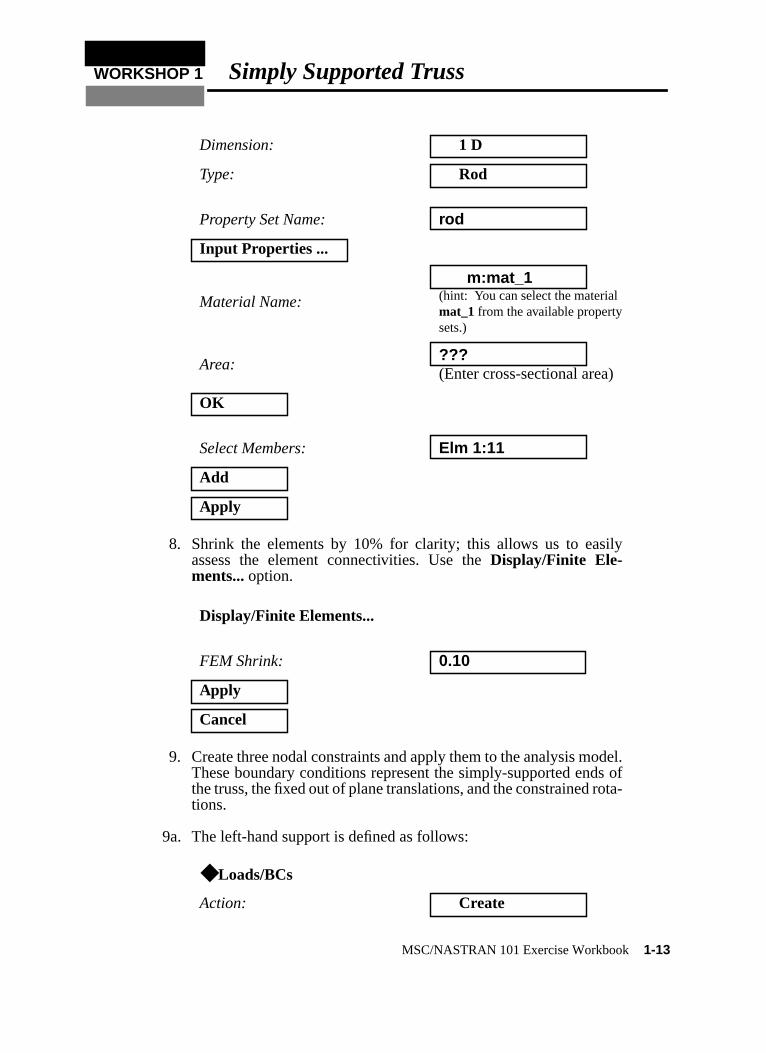
8. Shrink the elements by 10% for clarity; this allows us to easilyassess the element connectivities. Use theDisplay/Finite Ele-ments... option.
9. Create three nodal constraints and apply them to the analysis model.These boundary conditions represent the simply-supported ends ofthe truss, the fixed out of plane translations, and the constrained rota-tions.
9a. The left-hand support is defined as follows:
Dimension: 1 D
Type: Rod
Property Set Name: rod
Input Properties ...
Material Name:
m:mat_1(hint: You can select the materialmat_1 from the available propertysets.)
Area:???(Enter cross-sectional area)
OK
Select Members: Elm 1:11
Add
Apply
Display/Finite Elements...
FEM Shrink: 0.10
Apply
Cancel
◆ Loads/BCs
Action: Create
MSC/NASTRAN 101 Exercise Workbook1-13
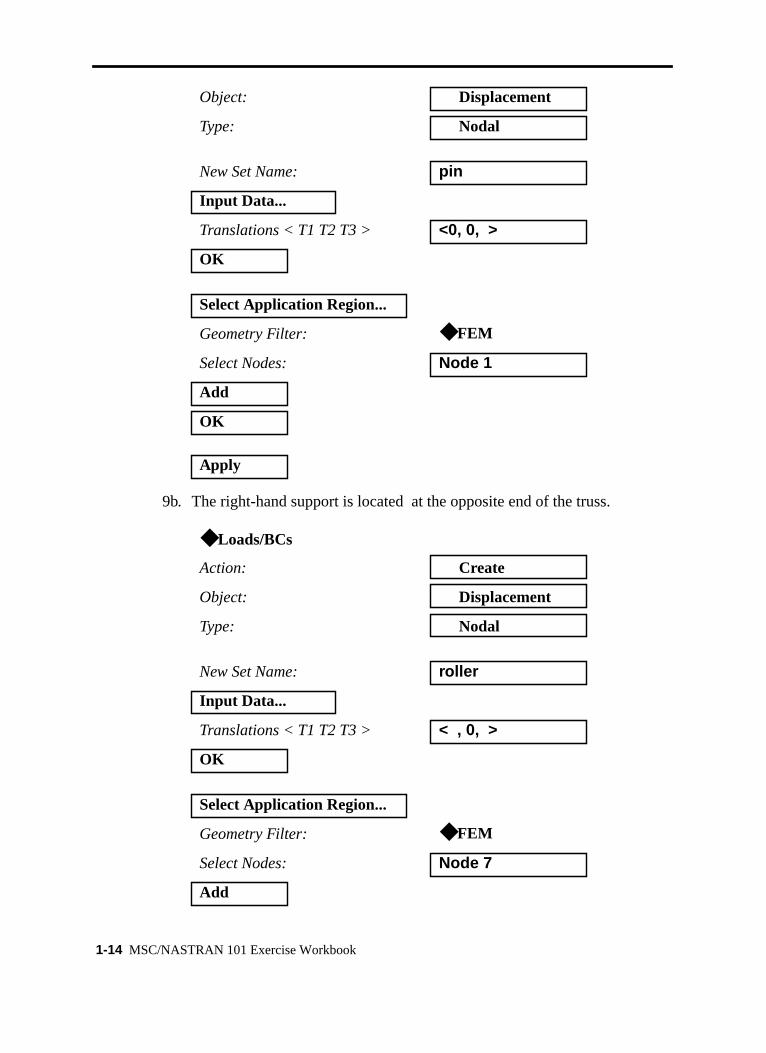
9b. The right-hand support is located at the opposite end of the truss.
Object: Displacement
Type: Nodal
New Set Name: pin
Input Data...
Translations < T1 T2 T3 > <0, 0, >
OK
Select Application Region...
Geometry Filter: ◆ FEM
Select Nodes: Node 1
Add
OK
Apply
◆ Loads/BCs
Action: Create
Object: Displacement
Type: Nodal
New Set Name: roller
Input Data...
Translations < T1 T2 T3 > < , 0, >
OK
Select Application Region...
Geometry Filter: ◆ FEM
Select Nodes: Node 7
Add
1-14 MSC/NASTRAN 101 Exercise Workbook
WORKSHOP 1 Simply Supported Truss
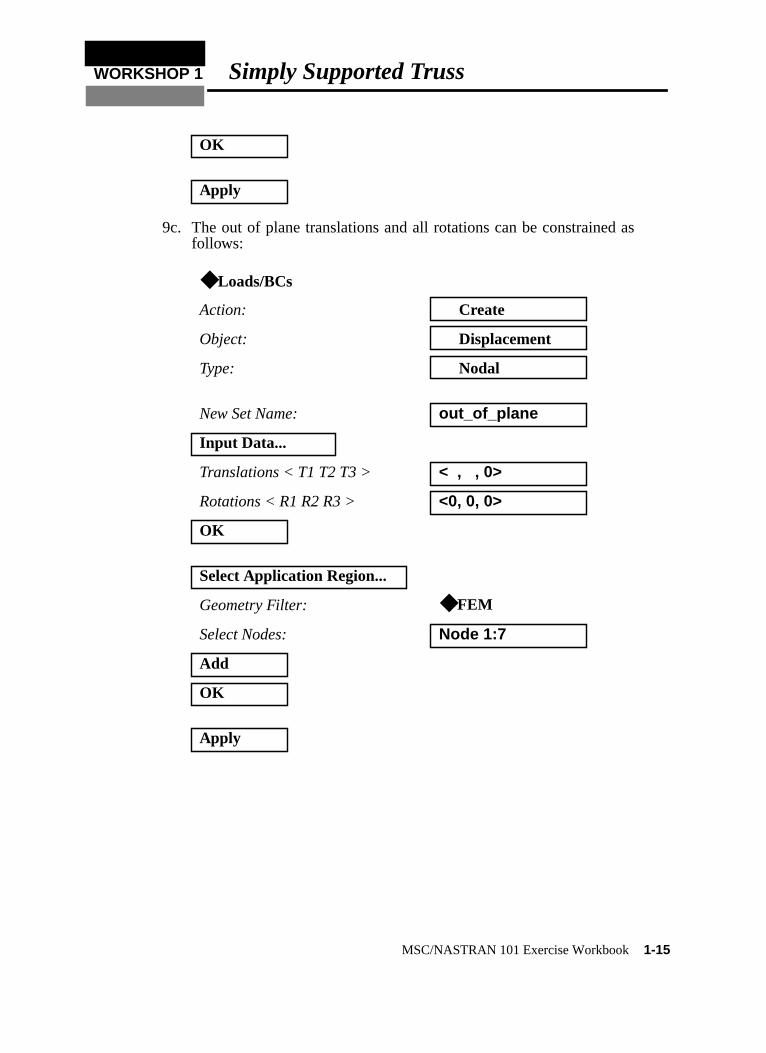
9c. The out of plane translations and all rotations can be constrained asfollows:
OK
Apply
◆ Loads/BCs
Action: Create
Object: Displacement
Type: Nodal
New Set Name: out_of_plane
Input Data...
Translations < T1 T2 T3 > < , , 0>
Rotations < R1 R2 R3 > <0, 0, 0>
OK
Select Application Region...
Geometry Filter: ◆ FEM
Select Nodes: Node 1:7
Add
OK
Apply
MSC/NASTRAN 101 Exercise Workbook1-15
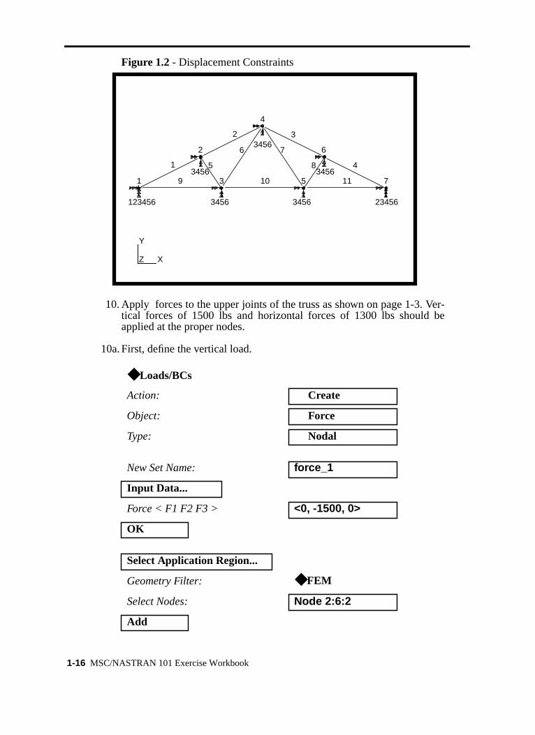
Figure 1.2 - Displacement Constraints
10. Apply forces to the upper joints of the truss as shown on page 1-3. Ver-tical forces of 1500 lbs and horizontal forces of 1300 lbs should beapplied at the proper nodes.
10a. First, define the vertical load.
◆ Loads/BCs
Action: Create
Object: Force
Type: Nodal
New Set Name: force_1
Input Data...
Force < F1 F2 F3 > <0, -1500, 0>
OK
Select Application Region...
Geometry Filter: ◆ FEM
Select Nodes: Node 2:6:2
Add
1
2 3
45
6 7
8
9 10 11
123456
3456
3456
3456
3456
3456
23456
1
2
3
4
5
6
7
X
Y
Z
1-16 MSC/NASTRAN 101 Exercise Workbook

WORKSHOP 1 Simply Supported Truss
Figure 1.3 - Vertical Forces
11. Next, define the horizontal forces.
OK
Apply
◆ Loads/BCs
Action: Create
Object: Force
Type: Nodal
New Set Name: force_2
Input Data...
Force < F1 F2 F3 > <-1300, 0, 0>
OK
Select Application Region...
Geometry Filter: ◆ FEM
1500.
1
2 3
45
6 7
8
9 10 11
123456
3456
3456
3456
3456
3456
23456
1
2
3
4
5
6
7
X
Y
Z
1500.1500.
MSC/NASTRAN 101 Exercise Workbook1-17
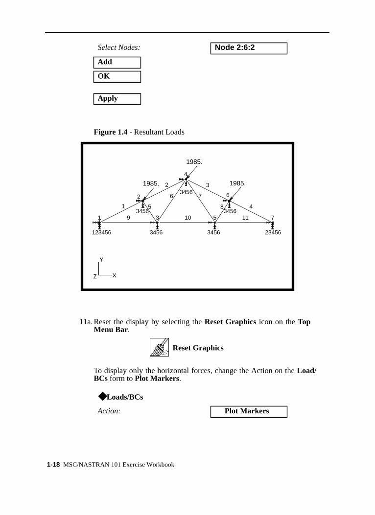
Figure 1.4 - Resultant Loads
11a. Reset the display by selecting theReset Graphicsicon on theTopMenu Bar.
To display only the horizontal forces, change the Action on theLoad/BCs form toPlot Markers.
Select Nodes: Node 2:6:2
Add
OK
Apply
◆ Loads/BCs
Action: Plot Markers
1985.
1
2 3
45
6 7
8
9 10 11
123456
3456
3456
3456
3456
3456
23456
1
2
3
4
5
6
7
X
Y
Z
1985.
1985.
Reset Graphics
1-18 MSC/NASTRAN 101 Exercise Workbook
WORKSHOP 1 Simply Supported Truss
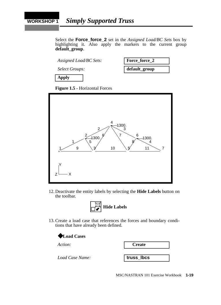
Select theForce_force_2 set in theAssigned Load/BC Setsbox byhighlighting it. Also apply the markers to the current groupdefault_group.
Figure 1.5 - Horizontal Forces
12. Deactivate the entity labels by selecting theHide Labels button onthe toolbar.
13. Create a load case that references the forces and boundary condi-tions that have already been defined.
Assigned Load/BC Sets: Force_force_2
Select Groups: default_group
Apply
◆ Load Cases
Action: Create
Load Case Name: truss_lbcs
1300.
1300.
1300.
Y
Z
1
2
3
4
5
6
7
1
2 3
45
6 7
8
9 10 11
X
Hide Labels
MSC/NASTRAN 101 Exercise Workbook1-19
-
.
e
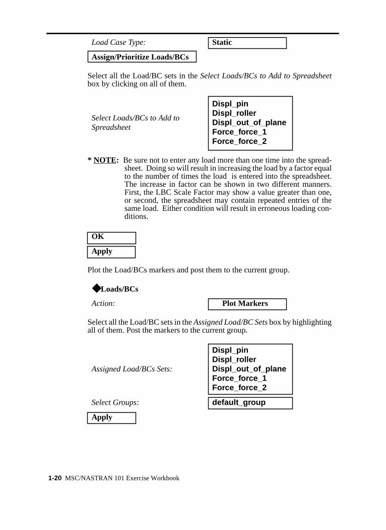
Select all the Load/BC sets in theSelect Loads/BCs to Add to Spreadsheetbox by clicking on all of them.
* NOTE: Be sure not to enter any load more than one time into the spreadsheet. Doing so will result in increasing the load by a factor equalto the number of times the load is entered into the spreadsheetThe increase in factor can be shown in two different manners.First, the LBC Scale Factor may show a value greater than one,or second, the spreadsheet may contain repeated entries of thsame load. Either condition will result in erroneous loading con-ditions.
Plot the Load/BCs markers and post them to the current group.
Select all the Load/BC sets in theAssigned Load/BC Setsbox by highlightingall of them. Post the markers to the current group.
Load Case Type: Static
Assign/Prioritize Loads/BCs
Select Loads/BCs to Add toSpreadsheet
Displ_pinDispl_rollerDispl_out_of_planeForce_force_1Force_force_2
OK
Apply
◆ Loads/BCs
Action: Plot Markers
Assigned Load/BCs Sets:
Displ_pinDispl_rollerDispl_out_of_planeForce_force_1Force_force_2
Select Groups: default_group
Apply
1-20 MSC/NASTRAN 101 Exercise Workbook
WORKSHOP 1 Simply Supported Truss
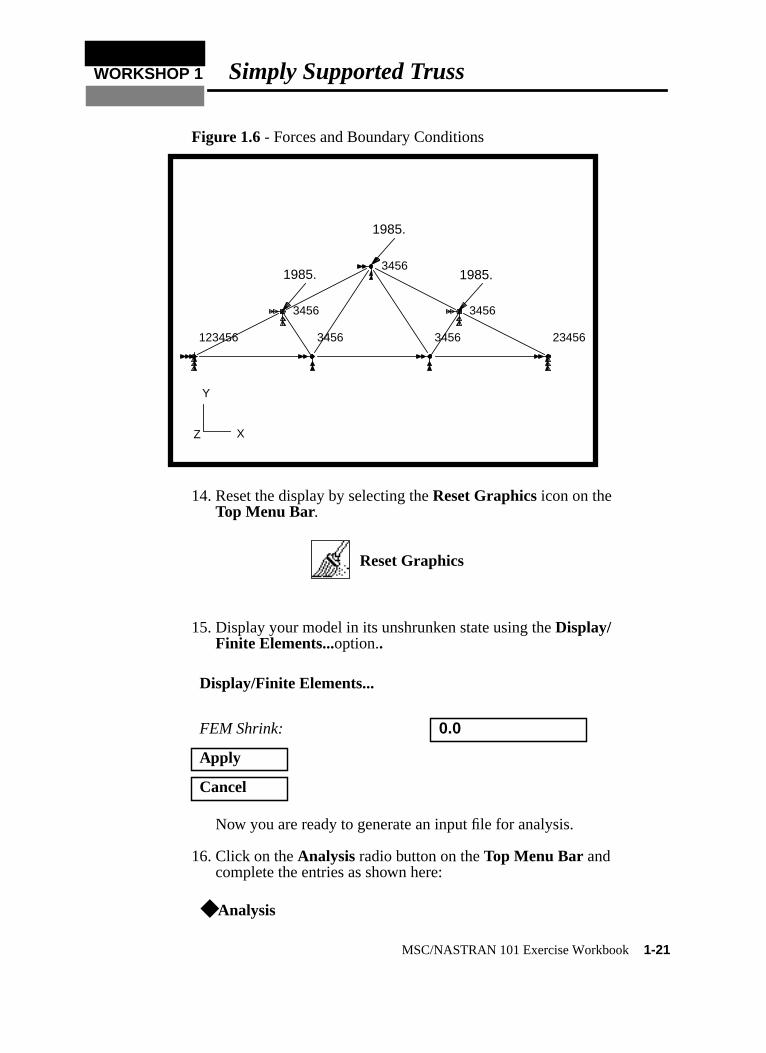
Figure 1.6 - Forces and Boundary Conditions
14. Reset the display by selecting theReset Graphics icon on theTop Menu Bar.
15. Display your model in its unshrunken state using theDisplay/Finite Elements...option..
Now you are ready to generate an input file for analysis.
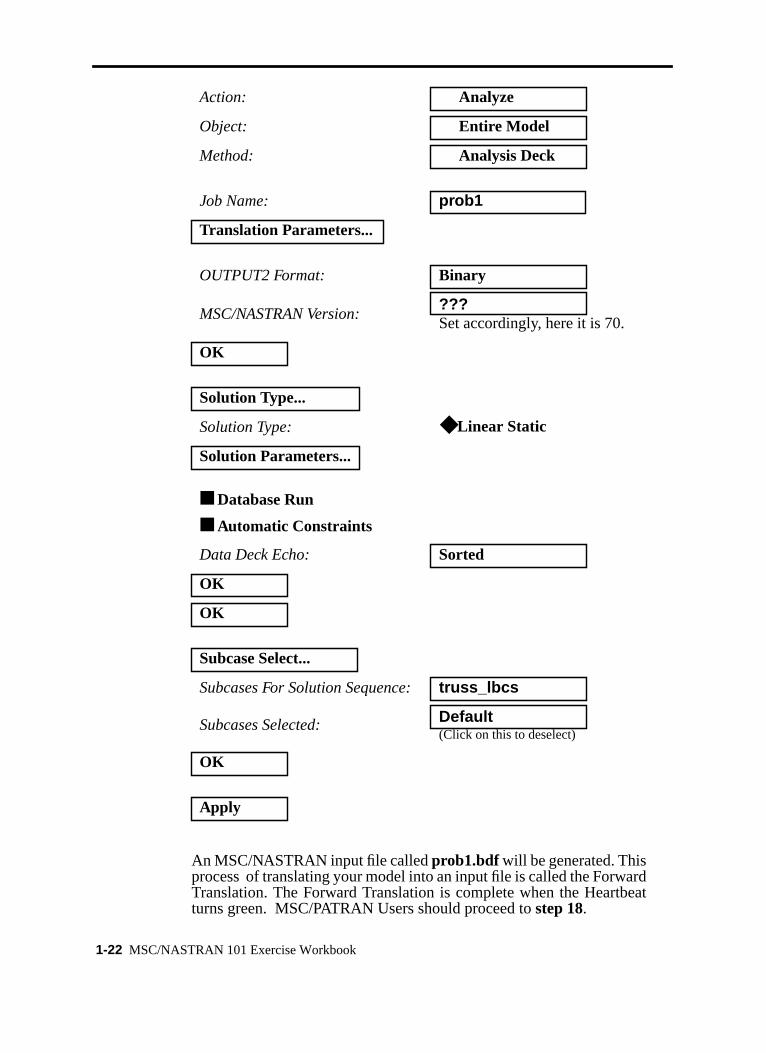
16. Click on theAnalysis radio button on theTop Menu Bar andcomplete the entries as shown here:
Display/Finite Elements...
FEM Shrink: 0.0
Apply
Cancel
◆ Analysis
1985.
XYZ
123456
3456
3456
3456
3456
3456
23456
X
Y
Z
1985.
1985.
Reset Graphics
MSC/NASTRAN 101 Exercise Workbook1-21
t
An MSC/NASTRAN input file calledprob1.bdf will be generated. Thisprocess of translating your model into an input file is called the ForwardTranslation. The Forward Translation is complete when the Heartbeaturns green. MSC/PATRAN Users should proceed tostep 18.
Action: Analyze
Object: Entire Model
Method: Analysis Deck
Job Name: prob1
Translation Parameters...
OUTPUT2 Format: Binary
MSC/NASTRAN Version:???Set accordingly, here it is 70.
OK
Solution Type...
Solution Type: ◆ Linear Static
Solution Parameters...
■ Database Run
■ Automatic Constraints
Data Deck Echo: Sorted
OK
OK
Subcase Select...
Subcases For Solution Sequence:truss_lbcs
Subcases Selected: Default(Click on this to deselect)
OK
Apply
1-22 MSC/NASTRAN 101 Exercise Workbook
WORKSHOP 1 Simply Supported Truss
Generating an input file for MSC/NASTRAN Users:
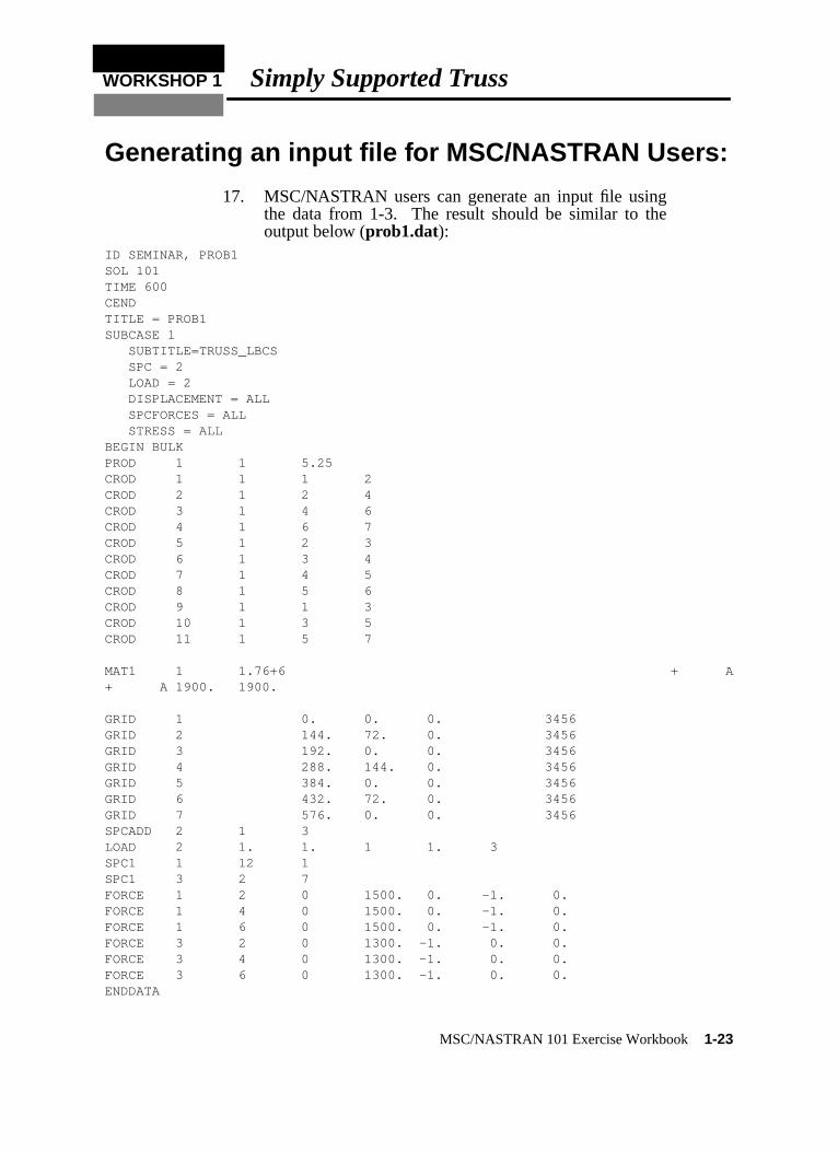
17. MSC/NASTRAN users can generate an input file usingthe data from 1-3. The result should be similar to theoutput below (prob1.dat):
ID SEMINAR, PROB1SOL 101TIME 600CENDTITLE = PROB1SUBCASE 1 SUBTITLE=TRUSS_LBCS SPC = 2 LOAD = 2 DISPLACEMENT = ALL SPCFORCES = ALL STRESS = ALLBEGIN BULKPROD 1 1 5.25CROD 1 1 1 2CROD 2 1 2 4CROD 3 1 4 6CROD 4 1 6 7CROD 5 1 2 3CROD 6 1 3 4CROD 7 1 4 5CROD 8 1 5 6CROD 9 1 1 3CROD 10 1 3 5CROD 11 1 5 7
MAT1 1 1.76+6 + A+ A 1900. 1900.
GRID 1 0. 0. 0. 3456GRID 2 144. 72. 0. 3456GRID 3 192. 0. 0. 3456GRID 4 288. 144. 0. 3456GRID 5 384. 0. 0. 3456GRID 6 432. 72. 0. 3456GRID 7 576. 0. 0. 3456SPCADD 2 1 3LOAD 2 1. 1. 1 1. 3SPC1 1 12 1SPC1 3 2 7FORCE 1 2 0 1500. 0. -1. 0.FORCE 1 4 0 1500. 0. -1. 0.FORCE 1 6 0 1500. 0. -1. 0.FORCE 3 2 0 1300. -1. 0. 0.FORCE 3 4 0 1300. -1. 0. 0.FORCE 3 6 0 1300. -1. 0. 0.ENDDATA
MSC/NASTRAN 101 Exercise Workbook1-23
SUBMITTING THE INPUT FILE FOR MSC/NASTRANand MSC/PATRAN USERS:
18. Submit the input file to MSC/NASTRAN for analysis.
18a. To submit the MSC/PATRAN.bdf file, find an available UNIXshell window. At the command prompt enternastranprob1.bdf scr=yes. Monitor the run using the UNIXpscommand.
18b. To submit the MSC/NASTRAN.dat file, find an availableUNIX shell window and at the command prompt enternastranprob1 scr=yes. Monitor the run using the UNIX pscommand.
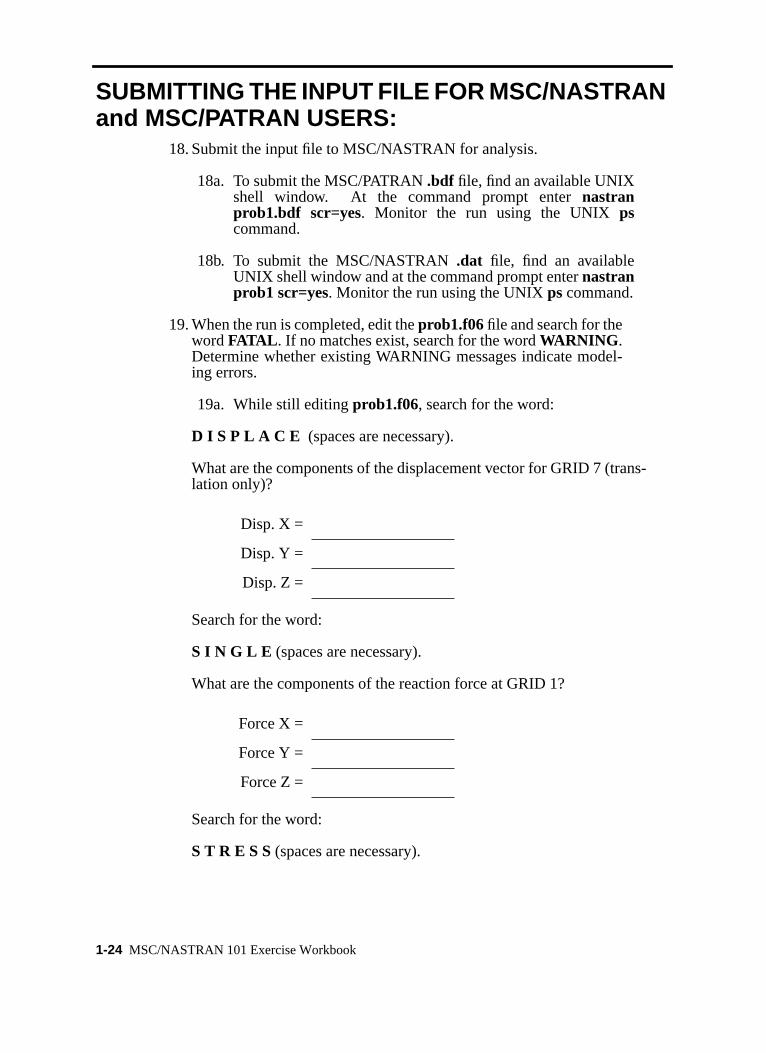
19. When the run is completed, edit theprob1.f06file and search for thewordFATAL . If no matches exist, search for the wordWARNING .Determine whether existing WARNING messages indicate model-ing errors.
19a. While still editingprob1.f06, search for the word:
D I S P L A C E (spaces are necessary).
What are the components of the displacement vector for GRID 7 (trans-lation only)?
Search for the word:
S I N G L E (spaces are necessary).
What are the components of the reaction force at GRID 1?
Search for the word:
S T R E S S (spaces are necessary).
Disp. X =
Disp. Y =
Disp. Z =
Force X =
Force Y =
Force Z =
1-24 MSC/NASTRAN 101 Exercise Workbook

WORKSHOP 1 Simply Supported Truss
What is the margin of safety for CROD 2?
What is the Axial Stress for CROD 7?
M.S. =
Axial Stress =
MSC/NASTRAN 101 Exercise Workbook1-25

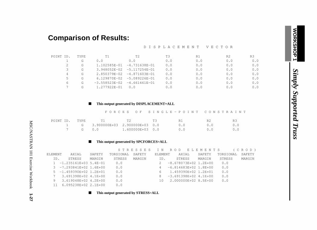
Comparison of Results:
20. Compare the results obtained in the.f06 file with the resultson the following page:
1-26 MSC/NASTRAN 101 Exercise Workbook
WO
RK
SH
OP
1S
imply S
upported Truss
SAFETY
MS
C/N
AS
TR
AN
101 Exercise W
orkbook1-27
Comparison of Results: D I S P L A C E M E N T V E C T O R
POINT ID. TYPE T1 T2 T3 R1 R2 R3 1 G 0.0 0.0 0.0 0.0 0.0 0.0 2 G 1.102585E-01 -4.731638E-01 0.0 0.0 0.0 0.0 3 G 3.948052E-02 -5.117254E-01 0.0 0.0 0.0 0.0 4 G 2.850379E-02 -4.871603E-01 0.0 0.0 0.0 0.0 5 G 6.129870E-02 -5.089226E-01 0.0 0.0 0.0 0.0 6 G -3.558523E-02 -4.661461E-01 0.0 0.0 0.0 0.0 7 G 1.277922E-01 0.0 0.0 0.0 0.0 0.0
■ This output generated by DISPLACEMENT=ALL
F O R C E S O F S I N G L E - P O I N T C O N S T R A I N T
POINT ID. TYPE T1 T2 T3 R1 R2 R3 1 G 3.900000E+03 2.900000E+03 0.0 0.0 0.0 0.0 7 G 0.0 1.600000E+03 0.0 0.0 0.0 0.0
■ This output generated by SPCFORCES=ALL
S T R E S S E S I N R O D E L E M E N T S ( C R O D ) ELEMENT AXIAL SAFETY TORSIONAL SAFETY ELEMENT AXIAL SAFETY TORSIONAL ID. STRESS MARGIN STRESS MARGIN ID. STRESS MARGIN STRESS MARGIN 1 -1.235161E+03 5.4E-01 0.0 2 -8.678073E+02 1.2E+00 0.0 3 -7.293841E+02 1.6E+00 0.0 4 -6.814683E+02 1.8E+00 0.0 5 -1.459390E+02 1.2E+01 0.0 6 1.459390E+02 1.2E+01 0.0 7 3.691398E+02 4.1E+00 0.0 8 -3.691398E+02 4.1E+00 0.0 9 3.619048E+02 4.2E+00 0.0 10 2.000000E+02 8.5E+00 0.0 11 6.095238E+02 2.1E+00 0.0
■ This output generated by STRESS=ALL
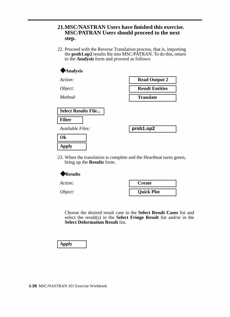
21.MSC/NASTRAN Users have finished this exercise.MSC/PATRAN Users should proceed to the nextstep.
22. Proceed with the Reverse Translation process, that is, importingtheprob1.op2results file into MSC/PATRAN. To do this, returnto theAnalysis form and proceed as follows:
23. When the translation is complete and the Heartbeat turns green,bring up theResultsform.
Choose the desired result case in theSelect Result Caseslist andselect the result(s) in theSelect Fringe Resultlist and/or in theSelect Deformation Result list.
◆ Analysis
Action: Read Output 2
Object: Result Entities
Method: Translate
Select Results File...
Filter
Available Files: prob1.op2
Ok
Apply
◆ Results
Action: Create
Object: Quick Plot
Apply
1-28 MSC/NASTRAN 101 Exercise Workbook

WORKSHOP 1 Simply Supported Truss
If you wish to reset your display graphics to the state it was in beforeyou began post-processing your model, remember to select theReset Graphics icon.
Quit MSC/PATRAN when you have completed this exercise.
Reset Graphics
MSC/NASTRAN 101 Exercise Workbook1-29

1-30 MSC/NASTRAN 101 Exercise Workbook