lintech 300series 400series catalog
TRANSCRIPT
8/12/2019 Lintech 300series 400series Catalog
http://slidepdf.com/reader/full/lintech-300series-400series-catalog 1/11
Front (1st page)
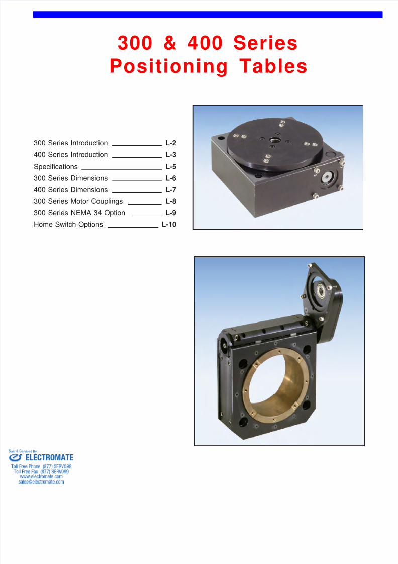
300 & 400 SeriesPositioning Tables
300 Series Introduction
400 Series Introduction
L-2
L-3
L-5Speci cations
300 Series Dimensions
400 Series Dimensions
L-6
L-7
L-8300 Series Motor Couplings
300 Series NEMA 34 Option L-9
L-10Home Switch Options
8/12/2019 Lintech 300series 400series Catalog
http://slidepdf.com/reader/full/lintech-300series-400series-catalog 2/11
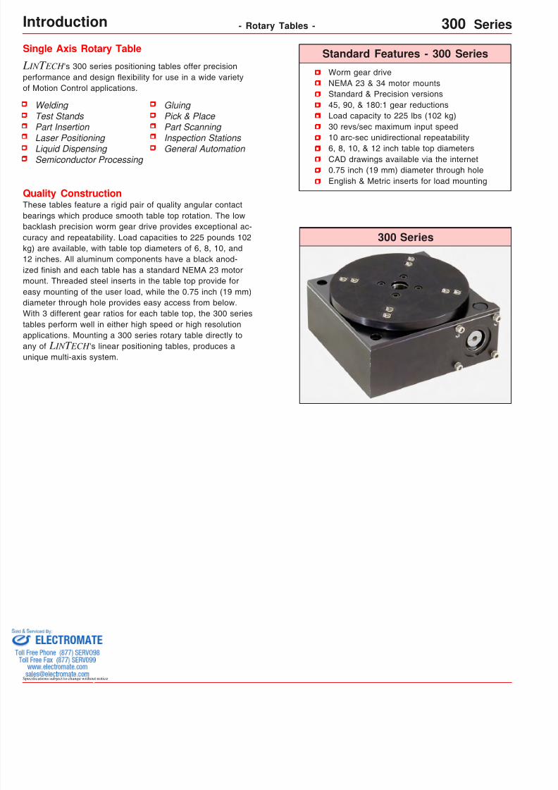
Worm gear driveNEMA 23 & 34 motor mountsStandard & Precision versions45, 90, & 180:1 gear reductionsLoad capacity to 225 lbs (102 kg)30 revs/sec maximum input speed
10 arc-sec unidirectional repeatability6, 8, 10, & 12 inch table top diametersCAD drawings available via the internet0.75 inch (19 mm) diameter through holeEnglish & Metric inserts for load mounting
300 Series
Standard Features - 300 SeriesSingle Axis Rotary Table
L IN T ECH 's 300 series positioning tables offer precisionperformance and design exibility for use in a wide varietyof Motion Control applications.
Specifcations subject to change without notice
Quality ConstructionThese tables feature a rigid pair of quality angular contactbearings which produce smooth table top rotation. The lowbacklash precision worm gear drive provides exceptional ac-curacy and repeatability. Load capacities to 225 pounds 102kg) are available, with table top diameters of 6, 8, 10, and12 inches. All aluminum components have a black anod-ized nish and each table has a standard NEMA 23 motormount. Threaded steel inserts in the table top provide foreasy mounting of the user load, while the 0.75 inch (19 mm)diameter through hole provides easy access from below.With 3 different gear ratios for each table top, the 300 seriestables perform well in either high speed or high resolutionapplications. Mounting a 300 series rotary table directly toany of L IN T ECH 's linear positioning tables, produces aunique multi-axis system.
Gluing Pick & Place Part Scanning
Inspection Stations General Automation
WeldingTest StandsPart Insertion
Laser Positioning Liquid DispensingSemiconductor Processing
Introduction - Rotary Tables - 300 Serie
8/12/2019 Lintech 300series 400series Catalog
http://slidepdf.com/reader/full/lintech-300series-400series-catalog 3/11
Specifcations subject to chan
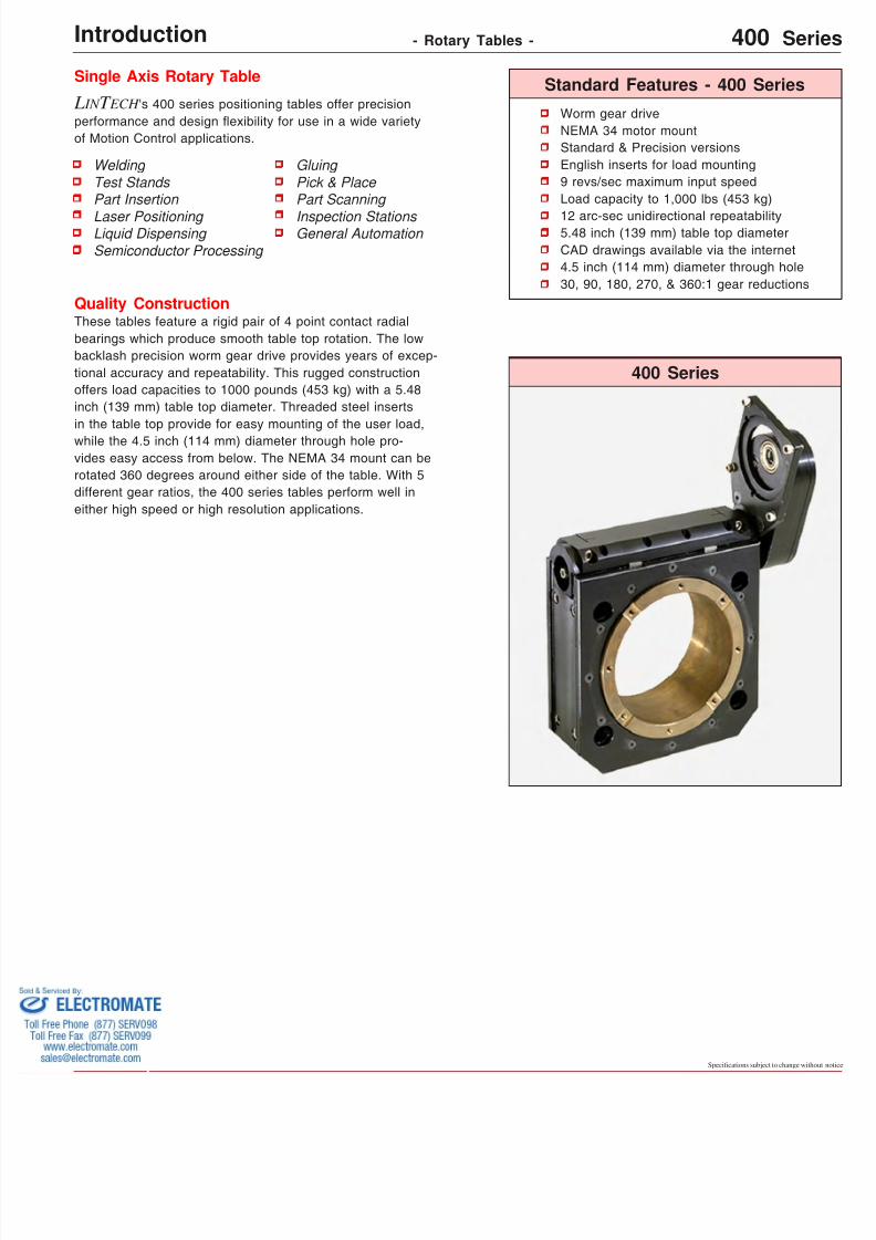
Worm gear driveNEMA 34 motor mountStandard & Precision versionsEnglish inserts for load mounting9 revs/sec maximum input speedLoad capacity to 1,000 lbs (453 kg)
12 arc-sec unidirectional repeatability5.48 inch (139 mm) table top diameterCAD drawings available via the internet4.5 inch (114 mm) diameter through hole30, 90, 180, 270, & 360:1 gear reductions
400 Series
Standard Features - 400 SeriesSingle Axis Rotary Table
L IN T ECH 's 400 series positioning tables offer precisionperformance and design exibility for use in a wide varietyof Motion Control applications.
Quality ConstructionThese tables feature a rigid pair of 4 point contact radialbearings which produce smooth table top rotation. The lowbacklash precision worm gear drive provides years of excep-tional accuracy and repeatability. This rugged constructionoffers load capacities to 1000 pounds (453 kg) with a 5.48inch (139 mm) table top diameter. Threaded steel insertsin the table top provide for easy mounting of the user load,while the 4.5 inch (114 mm) diameter through hole pro-vides easy access from below. The NEMA 34 mount can berotated 360 degrees around either side of the table. With 5different gear ratios, the 400 series tables perform well ineither high speed or high resolution applications.
Gluing Pick & Place Part Scanning
Inspection Stations General Automation
WeldingTest StandsPart Insertion
Laser Positioning Liquid DispensingSemiconductor Processing
Introduction - Rotary Tables - 400
8/12/2019 Lintech 300series 400series Catalog
http://slidepdf.com/reader/full/lintech-300series-400series-catalog 4/11
Specifcations subject to change without notice
(E) - English Interface
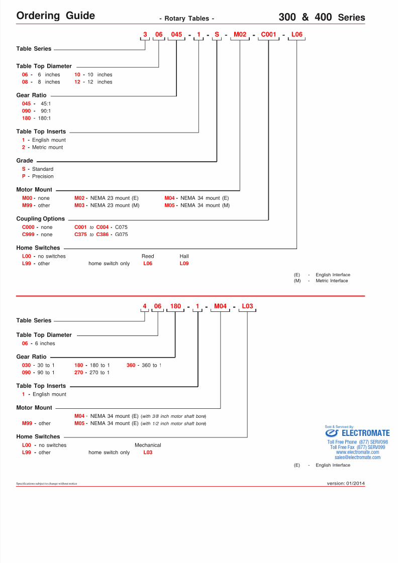
Ordering Guide - Rotary Tables - 300 & 400 Serie
Table Series
Table Top Diameter
Motor Mount
06 - 6 inches
M00 - none
Coupling OptionsC000 - none
L00 - no switches
C001 to C004 - C075C375 to C386 - G075
L99 - other
M99 - other
C999 - none
M02 C001- - L06-04506
M04 -M05 - NEMA 34 mount (M)
NEMA 34 mount (E)
home switch onlyReed HallL06 L09
S -1 -3
08 - 8 inches10 - 10 inches12 - 12 inches
Gear Ratio045 - 45:1090 - 90:1180 - 180:1
Table Top Inserts1 - English mount2 - Metric mount
GradeS - StandardP - Precision
M02 -M03 - NEMA 23 mount (M)
NEMA 23 mount (E)
Table Series
Table Top Inserts
Home SwitchesL00 - no switches
home switch onlyMechanical
L03 L99 - other
M04-- 1 - L03180064
1 - English mount
other
Motor Mount
M99 -
Gear Ratio
090 - 90 to 1180 - 180 to 1270 - 270 to 1
Table Top Diameter06 - 6 inches
360 - 360 to 1030 - 30 to 1
Home Switches
M04 - NEMA 34 mount (E) (with 3/8 inch motor shaft bore )
M05 - NEMA 34 mount (E) (with 1/2 inch motor shaft bore )
(E) - English Interface-(M) Metric Interface
version: 01/2014
8/12/2019 Lintech 300series 400series Catalog
http://slidepdf.com/reader/full/lintech-300series-400series-catalog 5/11
Specifcations subject to chan
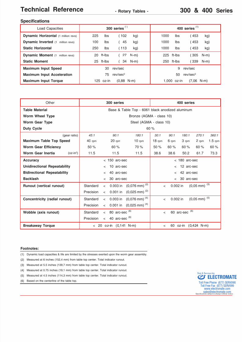
Unidirectional Repeatability
300 series
Worm Wheel Type
Backlash
Other
400 seriesLoad Capacities
Dynamic Horizontal (1 million revs) 225 lbs ( 102 kg)
250 lbs ( 113 kg)Static Horizontal
Dynamic Moment (1 million revs) 20 ft-lbs ( 27 N-m)
Static Moment 25 ft-lbs ( 34 N-m)
Duty Cycle
1000 lbs
1000 lbs
225 ft-lbs
250 ft-lbs
( 453 kg)
( 453 kg)
( 305 N-m)
( 339 N-m)
Speci cations
400 series
Bronze (AGMA - class 10)
60 %
Worm Gear Type Steel (AGMA - class 10)
Accuracy
Runout (vertical runout) 0.003 inStandard
Precision
150 arc-sec<
(0,076 mm)
0.001 in (0,025 mm)
0.002 in (0,05 mm)
Wobble (axis runout)
Breakaway Torque oz-in (0,42460 N-m)
Maximum Input Speed
Maximum Input Acceleration
300 series
75 rev/sec 2
30 rev/sec
50 rev/sec 2
9 rev/sec
Technical Reference - Rotary Tables - 300 & 400
Table Material Base & Table Top - 6061 black anodized aluminum
Bidirectional Repeatability
10 arc-sec<
40 arc-sec<
30 arc-sec<
180 arc-sec<
12 arc-sec<
42 arc-sec<
30 arc-sec<
Footnotes:
(1) Dynamic load capacities & life are limited by the stresses exerted upon the worm gear assembly.
(1) (1)
(2) Measured at 6 inches (152,4 mm) from table top center. Total indicator runout.
(2)
(2)
(3)
(6)Standard
Precision
(6)
(6)
(3) Measured at 5.5 inches (139,7 mm) from table top center. Total indicator runout.
(4) Measured at 0.75 inches (19,1 mm) from table top center. Total indicator runout.
(6) Based on the centerline of the table top.
oz-in (0,14120 N-m)
Worm Gear Ef ciency
Dynamic Inverted (1 million revs) 100 lbs ( 45 kg) 1000 lbs ( 453 kg)
Concentricity (radial runout) 0.002 in (0,05 mm) (5)0.003 inStandard
Precision
(0,076 mm)
0.001 in (0,025 mm)
(4)
(4)
< <
<
<
<
<
<
<
<
<
<
(5) Measured at 4.5 inches (114,3 mm) from table top center. Total indicator runout.
80 arc-sec
40 arc-sec
60 arc-sec
30:1 90:1 180:1 270:1 360:145:1 90:1 180:1
Maximum Table Top Speed 40 rpm 20 rpm 10 rpm 18 rpm 6 rpm 3 rpm 2 rpm 1.5 rp
60 %50 % 70 % 50 %
Worm Gear Inertia 11.5 11.5 11.5 38.6 73.361.750.238.6(oz-in 2)
(gear ratio)
60 %60 %60 %60 %
Maximum Input Torque 125 oz-in (0,88 N-m) 1,000 oz-in (7,06 N-m)

8/12/2019 Lintech 300series 400series Catalog
http://slidepdf.com/reader/full/lintech-300series-400series-catalog 6/11
Specifcations subject to change without notice
Dimensions
F
Threaded Stainless Steel Inserts: English Inserts (-1) : (8) 1/4-20 x B inch deep TYP
Metric Inserts (-2) : (8) M6 thd. x B mm deep TYP
.281 (7,1) Dia.Thru Holes,C' Bored Opposite Side
.438 (11,1) x I Deep
.190(4,83)
(4) Holes on 2.625 (66,68) Bolt Circle Dia. English Mount (M02) : #10-24 thd. Metric Mount (M03) : M6 thd.
inches(mm)
.750(19,05)
NEMA 23 Motor Mount:
For optional coupling info see page L-8
ModelNumber lbs
(kg)
inches(mm)
C
inches(mm)
Mounting Dimensions
11.0(5,0)
306xxx-1-S
A
Table Dimensions
0.375(9,5)
B
2.500(63,5)
2.930(74,4)
TableWeight
12.0(5,4)308xxx-1-S 0.500(12,7) 2.500(63,5) 3.055(77,6)
6.000(152,4)
8.000(203,2)
33.0(15,0)
310xxx-1-S 0.750(19,0)
2.650(67,3)
3.455(87,8)
10.000(254,0)
Dimensions & Speci cations
36.0(16,3)
312xxx-1-S 0.750(19,0)
2.650(67,3)
3.455(87,8)
12.000(304,8)
o
D
(1) The 8 inch (203, 2 mm), and 12 inch (304,8 mm), diameter table tops will extend outside the H body envelope.
.500(12,70)
(2)
(2) These dimensions valid for the 6 inch (152,4 mm), and 8 inch (203, 2) table top diameters only.
(2)
E(1)
G
G
H
G G
H
C
D
B
A
E F Glbs(kg)
1.1(0,5)
Table TopWeight
2.5(1,2)
5.7(2,6)
7.2(3,3)
H
5.000(127,0)
6.000(152,4)
8.000(203,2)
10.000(254,0)
4.000(101,6)
4.000(101,6)
6.000(152,4)
8.000(203,2)
2.500(63,5)
2.500(63,5)
4.500(114,3)
4.500(114,3)
6.000(152,4)
6.000(152,4)
10.000(254,0)
10.000(254,0)
I
2.000(50,8)
2.000(50,8)
0.250(6,3)
0.250(6,3)
xxx = 045; 45 to 1 gear ratio
xxx = 090; 90 to 1 gear ratio
xxx = 180; 180 to 1 gear ratio
Technical Reference - Rotary Tables - 300 Serie
(3) Dimension includes a 0.055 inch (1,4 mm) gap between the rotating table top and the table base.
(3)
Cap plug shown:Optional home switch connector location(see page L-10)
Worm gear pre-load adjustment screw:(Should NOT be eld adjusted - contact factory)
.500(12,70)
.500(12,70)
2.042(51,87)
1.190(30,23)
1.00 (25,40) Thru Dia.
1.502 (38,15) Pilot Dia. TYP , 0.075" (1,91) DEEP
8/12/2019 Lintech 300series 400series Catalog
http://slidepdf.com/reader/full/lintech-300series-400series-catalog 7/11
Specifcations subject to chan
ModelNumber
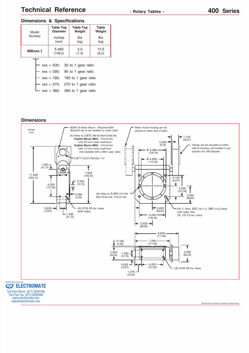
406xxx-1
Dimensions & Speci cations
xxx = 090; 90 to 1 gear ratio
xxx = 180; 180 to 1 gear ratio
inches(mm)
5.480(139,2)
Table TopDiameter
lbs(kg)
3.0(1,4)
Table TopWeight
lbs(kg)
13.5(6,2)
TableWeight
xxx = 270; 270 to 1 gear ratio
xxx = 360; 360 to 1 gear ratio
Dimensions
Flange can be mounted on eitheside of housing, and located in position thru 360 degrees.
2.877 (73,07) Pilot Dia. TYP
(4) Holes on 3.875 (98,42) Bolt Circle Dia. English Mount (M04) : #10-24 thd. * with 3/8 inch motor shaft bore English Mount (M05) : #10-24 thd. * with 1/2 inch motor shaft bore (not available with a 360:1 gear ratio)
inches(mm)
4.500(114,30)
NEMA 34 Motor Mount: Requires #304 Woodruff key to be installed on motor shaft
o
4.250(107,95)
0.625(15,87)
1.250(31,75)
11.500(292,10)
1.250(31,75)
5.480(139,19)
o
Motor mount housing can beplaced on either side of table.
0.090(2,29)
0.500(12,70)
2.625(66,67)
5.250(133,35)
3.500(88,90)
7.620(193,55)
2.125(53,97)
4.250(107,95)
3.500(88,90)
(4) 5/16-18 thd. Holes(both sides)
(4) 5/16-18 thd. Holes
(4) C" Bore .635 (16,1) x .560 (14,2) deboth sides, then(4) 1/2-13 thd. Holes
7.000(177,80)
8.625(177,80)
1.250(31,75)
0.160(4,06)
2.500(63,50)
0.625(15,87)
1.375(34,92)
4.250(107,95)
3.250(82,55)
(8) Holes on 5.000 (127,00)Bolt Circle Dia., #10-24 thd.
0.250(6,35)
1.125(28,57)
Technical Reference - Rotary Tables - 400
xxx = 030; 30 to 1 gear ratio
8/12/2019 Lintech 300series 400series Catalog
http://slidepdf.com/reader/full/lintech-300series-400series-catalog 8/11
Specifcations subject to change without notice
Options - Rotary Tables - 300 Serie
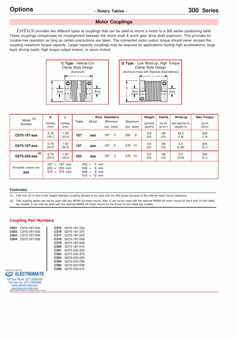
C075-187-250C075-187-005
C075-187-006C075-187-008
C001C002
C003C004
G075-187-250G075-187-375
G075-187-005G075-187-006G075-187-008G075-187-010G075-250-250G075-250-375G075-250-005G075-250-006G075-250-008G075-250-010
C375C376
C377C378C379C380C381C382C383C384C385C386
D L Bore Diametersinches(mm)
oz-in(N-m)
Max TorqueTable Wind-uparc-sec/oz-in
(deg/N-m)
Inertiaoz-in 2
(g-cm 2)
Weightounces(grams)
Motor Maximum
(mm)(in)
Minimum
(mm)(in)inches(mm)
C075-187-aaa 0.75(19,1)
1.00(25,4)
200(1,4)
0.8(23)aaa .187 5187 45.0
(1,8).06(10)
G075-250-aaa 0.79(20,0)
1.02(26,0) aaa .187 5250
.250 8
.375 10
aaa
187250375
===
.187
.250
.375
inchinchinch
005006008010
====
568
10
mmmmmmmm
Possible values for
L IN T ECH provides two different types of couplings that can be used to mount a motor to a 300 series positioning table.These couplings compensate for misalignment between the motor shaft & worm gear drive shaft extension. This provides fortrouble-free operation as long as certain precautions are taken. The connected motor output torque should never exceed thecoupling maximum torque capacity. Larger capacity couplings may be required for applications having high accelerations, largeback driving loads, high torque output motors, or servo motors.
Coupling Part Numbers
Motor Couplings
G075-187-aaa 0.79(20,0)
1.02(26,0)
300(2,1)
0.8(23)aaa .187 5187 2.0
(0,08).06(10).375 10
300(2,1)
0.8(23)
2.0(0,08)
.06(10)
0.85 inch (21,6 mm) is the largest diameter coupling allowed to be used with the 300 series because of the internal motor mount clearance.
Footnotes:
(1)
(2) This coupling option can not be used with any NEMA 23 motor mount. Also, it can not be used with the optional NEMA 34 motor mount for the 6 and 10 inch tabletop models. It can only be used with the optional NEMA 34 motor mount for the 8 and 12 inch table top models.
(2)
(1)ModelNumber
G Type - Low Wind-up, High TorqueClamp Style Design
(Aluminum Hubs with Stainless Steel Bellows)
L
DBore Bore
DBore
L
C Type - Helical-CutClamp Style Design
(Aluminum)
Bore
8/12/2019 Lintech 300series 400series Catalog
http://slidepdf.com/reader/full/lintech-300series-400series-catalog 9/11
8/12/2019 Lintech 300series 400series Catalog
http://slidepdf.com/reader/full/lintech-300series-400series-catalog 10/11
Specifcations subject to change without notice
- Rotary Tables - 300 & 400 SerieOptions
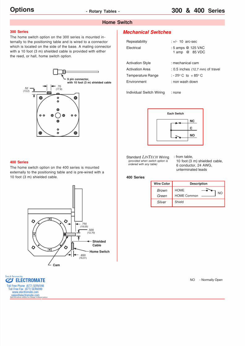
Mechanical Switches
Repeatability : +/- 10 arc-sec
Electrical : 5 amps @ 125 VAC 1 amp @ 85 VDC
Activation Area : 0.5 inches (12,7 mm) of travel
Temperature Range : - 25 o C to + 85 o C
Activation Style : mechanical cam
Environment : non wash down
Individual Switch Wiring : none
Description
HOME
HOME CommonN
Wire Color
Brown Green
ShieldSilver
NO
NC
C
Each Switch
: from table, 10 foot (3 m) shielded cable,
6 conductor, 24 AWG,unterminated leads
Standard L IN T ECH Wiring(provided when switch option isordered with any table)
Home Switch
NO - Normally Ope
400 Series
300 Series
.70(17,8).52
(13,2)
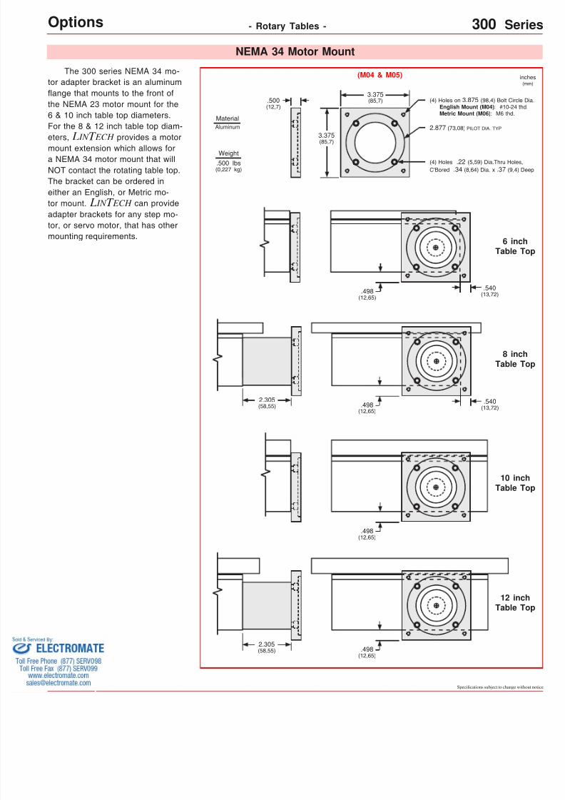
The home switch option on the 300 series is mounted in -ternally to the positioning table and is wired to a connectorwhich is located on the side of the base. A mating connectorwith a 10 foot (3 m) shielded cable is provided with eitherthe reed, or hall, home switch option.
9 pin connector,with 10 foot (3 m) shielded cable
400 SeriesThe home switch option on the 400 series is mountedexternally to the positioning table and is pre-wired with a10 foot (3 m) shielded cable.
Home Switch.650
(16,51)
.750(19,05)
.500(12,70)
Cam
ShieldedCable
8/12/2019 Lintech 300series 400series Catalog
http://slidepdf.com/reader/full/lintech-300series-400series-catalog 11/11
- Rotary Tables - 300 & 400Options
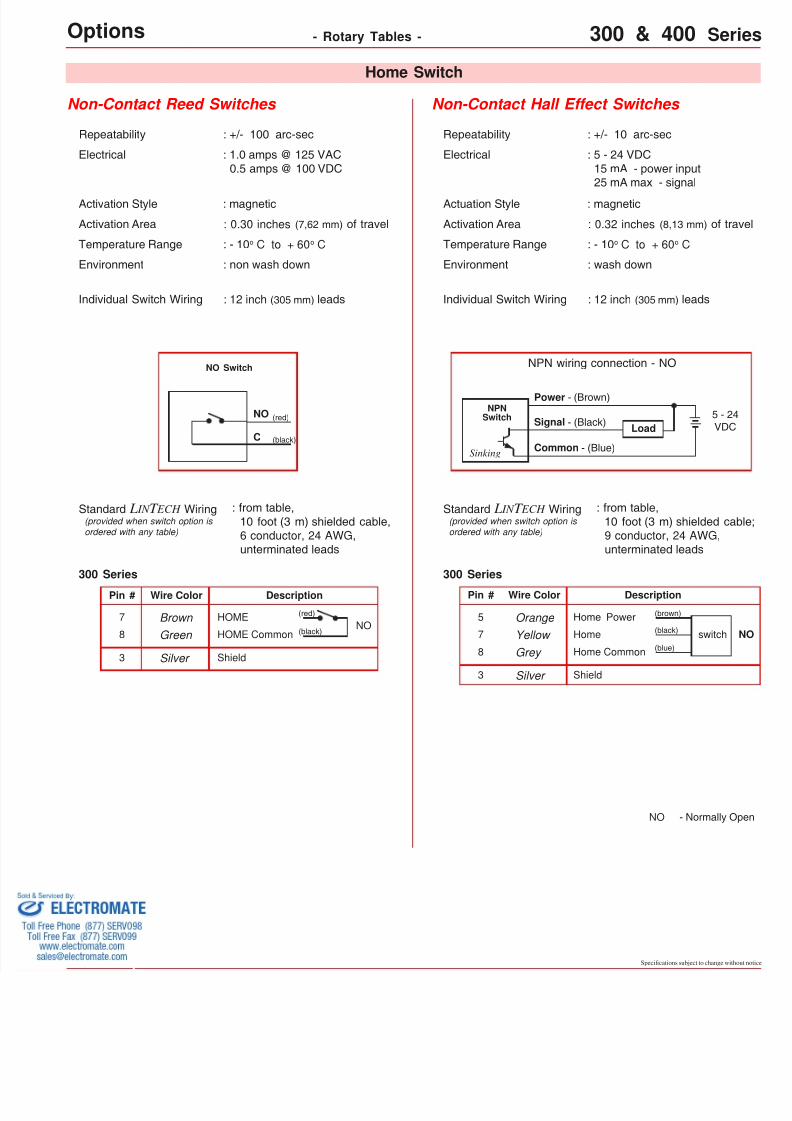
Non-Contact Reed Switches Non-Contact Hall Effect Switches
Repeatability : +/- 100 arc-sec
Electrical : 1.0 amps @ 125 VAC 0.5 amps @ 100 VDC
Repeatability : +/- 10 arc-sec
Electrical : 5 - 24 VDC 15 mA - power input 25 mA max - signal
Actuation Style : magnetic
Activation Area : 0.32 inches (8,13 mm)
Temperature Range : - 10 o C to + 60 o C
Environment : wash down
Individual Switch Wiring : 12 inch (305 mm) leads
NPN wiring connection - NO
Load
Power - (Brown)
Signal - (Black)
Common - (Blue)
: from table, 10 foot (3 m) shielded
9 conductor, 24 AWG,unterminated leads
Standard L IN T ECH Wiring
NPNSwitch
DescriptionWire Color
Orange Home Power
Yellow Home
Grey Home Common
sw(black)
(blue)
ShieldSilver
(brown)
Activation Area : 0.30 inches (7,62 mm) of travel
Temperature Range : - 10 o C to + 60 o C
Activation Style : magnetic
Environment : non wash down
Individual Switch Wiring : 12 inch (305 mm) leads
Description
HOME
HOME CommonNO
Wire Color
Brown Green
ShieldSilver
(red)
(black)
(red)
(black)
NO
C
NO Switch
: from table, 10 foot (3 m) shielded cable,
6 conductor, 24 AWG,unterminated leads
Standard L IN T ECH Wiring(provided when switch option isordered with any table)
(provided when switch option isordered with any table)
Home Switch
Sinking
NO - Norm
300 Series
Pin #
7
8
300 Series
Pin #
5
7
83
3