literature assembly 911-0566 - bard hvac
TRANSCRIPT

Literature Assembly
911-0566-1 BOOK 1 OF 2
Contains The Following:
2100-479 Servicing Procedures
2100-549(Z) I-TEC Series Heat Pump Manual
2110-1538(J) Replacement Parts Manual
7960-420 Warranty


Manual 2100-479Page 1 of 11
Manual No.: 2100-479Supersedes: NEWFile: Volume I, Tab 1Date: 03-08-07
SERVICING PROCEDURE
R-410ALEAK TEST EVACUATION CHARGING
Bard Manufacturing Company, Inc.Bryan, Ohio 43506
Since 1914...Moving ahead, just as planned.

Manual 2100-479Page 2 of 11
Recovery Equipment Rated for R-410A ...................3Leak Detectors .........................................................3Gauge Manifold ........................................................3Attaching Gauge Manifold ........................................3Attaching Manifold Hose to Schrader Valve .............4Leak Test ..................................................................4Evacuation ........................................................ 4 & 5Charging ..................................................................5Preliminary Charging Steps .....................................5Charging the System by Weight ..............................5
CONTENTSGeneral
Troubleshooting the Mechanical SystemAir Conditioning & Heat Pump - Cooling .............9Low Suction — Low Head Pressure .........................9High Suction — Low Head Pressure ........................9Low Suction — High Head Pressure ........................9High Suction — High Head Pressure ........................9Heat Pump - Heating ..............................................9Low Suction — Low Head Pressure .........................9High Suction — Low Head Pressure ........................9Low Suction — High Head Pressure ........................9High Suction — High Head Pressure ........................9
FiguresFigure 1: Typical AC System Cooling Cycle .............6Figure 2: Typical HP System Cooling Cycle ............7Figure 3: Heating Cycle ...........................................8
ChartsTroubleshooting Chart for Air Conditioners ............10Troubleshooting Chart for Air-to-Air Heat Pumps ....11

Manual 2100-479Page 3 of 11
Recovery equipment rated for R-410A refrigerantR-410A has an ozone depletion potential of zero, but must be reclaimed due to its global warming potential.
The gauge manifold set is specially designed to withstand the higher pressure associated with R-410A. Manifold sets are required to range up to 800 psig on the high side and 250 psig on the low side with a 250 psig low side retard.
All hoses must have a service rating of 800 psig. (This information will be indicated on the hoses.)
Vacuum Pump and micron gauge must be used when evacuating a system to 500 microns.
Leak DetectorsAn electronic leak detector capable of detecting HFC refrigerant can be used with R-410A refrigerant.
GENERAL
GAUGE MANIFOLD
A necessary instrument in checking and serving air conditioning and heat pump equipment is the gauge manifold. Its purpose is to determine the operating refrigerant pressures in order for the serviceman to analyze the condition of the system.
The valving on the manifold is so arranged that when the valves are closed (front-seated) the center port on the manifold is closed to the gauges and gauge ports. With the valves in the closed position, the gauge ports are still open to the gauges, permitting the gauges to register system pressures. Opening either valve opens the center port to that side of the manifold and system.
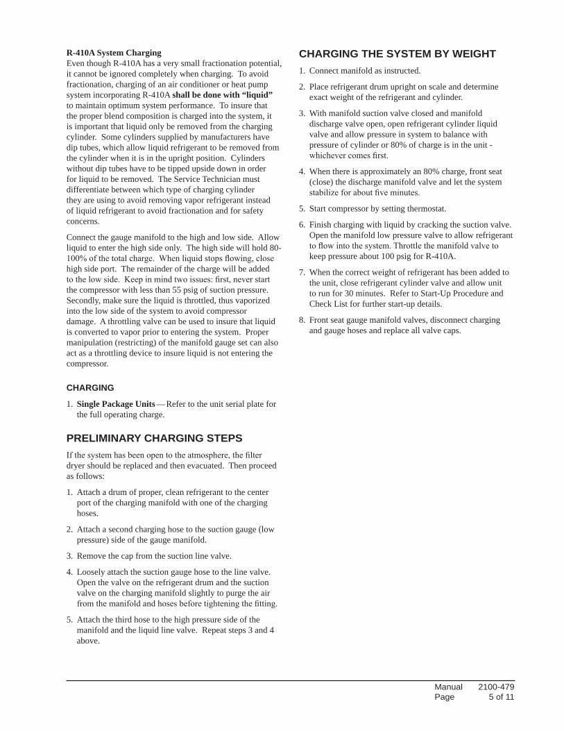
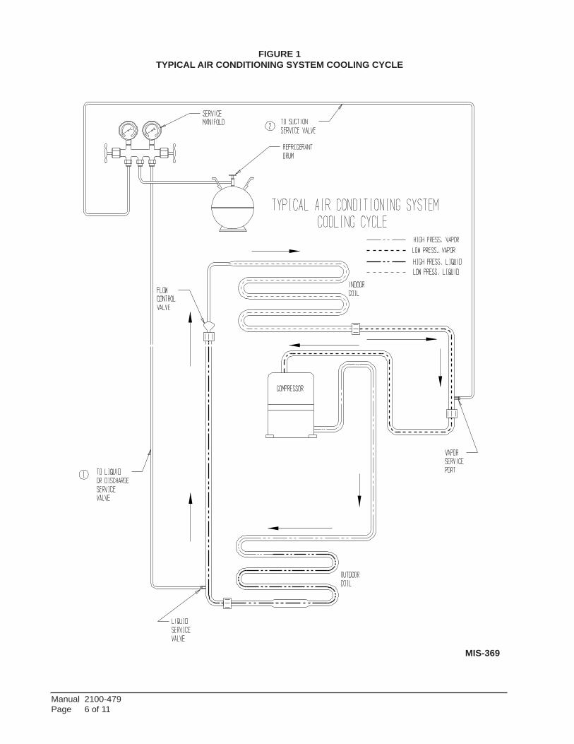
ATTACHING GAUGE MANIFOLDFor leak testing, purging, checking charge, charging liquid or evacuating, connect high pressure side of gauge manifold to Schrader valve on liquid or discharge line. Connect suction side of gauge manifold to Schrader valve on suction line. On heat pumps the suction line is between compressor and reversing valve.
WARNINGThe oils used with R-410A refrigerant are hydroscopic and absorb water from the atmosphere readily. Do not leave systems open to the atmosphere for more than 5 minutes. If the system has been open for more than 5 minutes, change the filter dryer immediately before evacuation. Then recharge the system to the factory specified charge.
WARNINGGauge manifold must be suitable for use with R-410A refrigerant and POE oils.

Manual 2100-479Page 4 of 11
Leak Test
1. Remove gauge port cap from suction and liquid service valve ports and attach manifold gauge hoses. Connect an upright R-410A drum to center port of gauge manifold. Open refrigerant drum valve and manifold high pressure gauge valve to pressurize system to a positive pressure with refrigerant vapor. Pressurize the complete system with dry nitrogen, or CO2 until the pressure reaches 200 psig. Do not exceed 250 psig.
2. Close manifold high pressure gauge valve. Check all soldered joints, including those on the evaporator coil with an Electronic Leak Detector suitable for use with HFC refrigerants or R-410A. If a leak is found which requires soldering, pressure in the system must be bled off since it is impossible to solder with unit pressurized. Be sure all leaks are located and marked before bleeding pressure from system.
ATTACHING MANIFOLD HOSE TO SCHRADER VALVE
1. Remove cap from valve.
2. Make sure gauge manifold valves are closed.
3. If hose does not have an unseating pin, a number 395 Superior or equivalent unseating coupler must be used.
4. Make sure coupler is lined up straight with Schrader valve. Screw coupler on to valve.
5. Open gauge manifold valve slightly and purge air from hose with refrigerant.
6. Read the suction pressure on compound gauge and heat pressure on pressure gauge.
7. To remove, push end of hose tight against end of Schrader valve and hold in place while quickly unscrewing coupler nut from Schrader valve.
8. Remove coupler from Schrader valve. Replace caps on valve.
3. Close drum valve and disconnect from center port. Release nitrogen or CO2 into the atmosphere through suction line of gauge manifold.
4. Correct any leaks and recheck. When leaks, if any, have been repaired, system is ready to be evacuated and charged. Relieve all pressure from the system down to 0 psig.
5. Changethefilterdryer.Whenleaks,ifany,havebeen repaired, system is ready to be evacuated and charged. Relieve all pressure from the system down to 0 psig.
EVACUATION
EvacuationAnevacuationto500micronsisusuallysufficienttoremovemoisture from a system using R-22 and mineral oil lubricant. A 500 micron evacuation, however, will not separate moisture from Polyol Ester oil (POE) inR-410A systems.
Inadditiontoa500micronevacuation,theliquidlinefilterdryer (R-410A compatible) must be replaced any time the systemisopen.Whenremovingafilterdryerfromasystem,do not use a torch; use a tubing cutter to avoid releasing moisture back into the system.
Older R-22 leak detectors, as well as halide torch leak detectors, will not detect leaks in R-410A systems. Never use air and R-410A to leak check, as the mixture may becomeflammableatpressuresabove1atmosphere.Asystem can be safely leak-checked by using nitrogen or a trace gas of R-410A and nitrogen.Remember: Always use a pressure regulator with nitrogen and a safety valve down stream - set at no more than 150 psig.
1. Evacuate system to less than 500 microns, using a good vacuum pump and an accurate high vacuum gauge. Operate the pump below 500 microns for 60 minutes and then close valve to the vacuum pump. Allow the system to stand for 30 additional minutes to be sure a 500 micron vacuum or less is maintained.
2. Disconnect charging line at vacuum pump and connect to refrigerant supply. Crack the cylinder valve and purge charging line at center on manifold. Then close cylinder valve.
3. The system is now ready for the correct operating charge of Refrigerant R-410A.
WARNING At no time use the compressor to
evacuate the system or any part of it.
WARNING As a safety measure, it is wise to detach refrigerant hoses at the lowest pressure readings on the system. To do this:
A. Put high pressure hose “B” on first. (Unit should not be running.)
B. Put low pressure hose “A” on second. (Unit should be running.)
Manual 2100-479Page 5 of 11
R-410A System ChargingEven though R-410A has a very small fractionation potential, it cannot be ignored completely when charging. To avoid fractionation, charging of an air conditioner or heat pump system incorporating R-410A shall be done with “liquid” to maintain optimum system performance. To insure that the proper blend composition is charged into the system, it is important that liquid only be removed from the charging cylinder. Some cylinders supplied by manufacturers have dip tubes, which allow liquid refrigerant to be removed from the cylinder when it is in the upright position. Cylinders without dip tubes have to be tipped upside down in order for liquid to be removed. The Service Technician must differentiate between which type of charging cylinder they are using to avoid removing vapor refrigerant instead of liquid refrigerant to avoid fractionation and for safety concerns.
Connect the gauge manifold to the high and low side. Allow liquid to enter the high side only. The high side will hold 80-100%ofthetotalcharge.Whenliquidstopsflowing,closehigh side port. The remainder of the charge will be added tothelowside.Keepinmindtwoissues:first,neverstartthe compressor with less than 55 psig of suction pressure. Secondly, make sure the liquid is throttled, thus vaporized into the low side of the system to avoid compressor damage. A throttling valve can be used to insure that liquid is converted to vapor prior to entering the system. Proper manipulation (restricting) of the manifold gauge set can also act as a throttling device to insure liquid is not entering the compressor.
CHARGING
1. Single Package Units — Refer to the unit serial plate for the full operating charge.
PRELIMINARY CHARGING STEPSIfthesystemhasbeenopentotheatmosphere,thefilterdryer should be replaced and then evacuated. Then proceed as follows:
1. Attach a drum of proper, clean refrigerant to the center port of the charging manifold with one of the charging hoses.
2. Attach a second charging hose to the suction gauge (low pressure) side of the gauge manifold.
3. Remove the cap from the suction line valve.
4. Loosely attach the suction gauge hose to the line valve. Open the valve on the refrigerant drum and the suction valve on the charging manifold slightly to purge the air fromthemanifoldandhosesbeforetighteningthefitting.
5. Attach the third hose to the high pressure side of the manifold and the liquid line valve. Repeat steps 3 and 4 above.
CHARGING THE SYSTEM BY WEIGHT1. Connect manifold as instructed.
2. Place refrigerant drum upright on scale and determine exact weight of the refrigerant and cylinder.
3. With manifold suction valve closed and manifold discharge valve open, open refrigerant cylinder liquid valve and allow pressure in system to balance with pressure of cylinder or 80% of charge is in the unit - whichevercomesfirst.
4. When there is approximately an 80% charge, front seat (close) the discharge manifold valve and let the system stabilizeforaboutfiveminutes.
5. Start compressor by setting thermostat.
6. Finish charging with liquid by cracking the suction valve. Open the manifold low pressure valve to allow refrigerant toflowintothesystem.Throttlethemanifoldvalvetokeep pressure about 100 psig for R-410A.
7. When the correct weight of refrigerant has been added to the unit, close refrigerant cylinder valve and allow unit to run for 30 minutes. Refer to Start-Up Procedure and Check List for further start-up details.
8. Front seat gauge manifold valves, disconnect charging and gauge hoses and replace all valve caps.
Manual 2100-479Page 6 of 11
FIGURE 1TYPICAL AIR CONDITIONING SYSTEM COOLING CYCLE
MIS-369
Manual 2100-479Page 7 of 11
FIGURE 2 TYPICAL HEAT PUMP SYSTEM COOLING CYCLE
MIS-368
Manual 2100-479Page 8 of 11
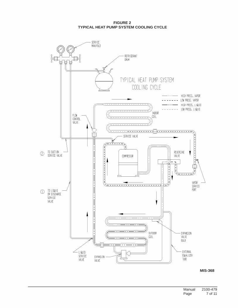
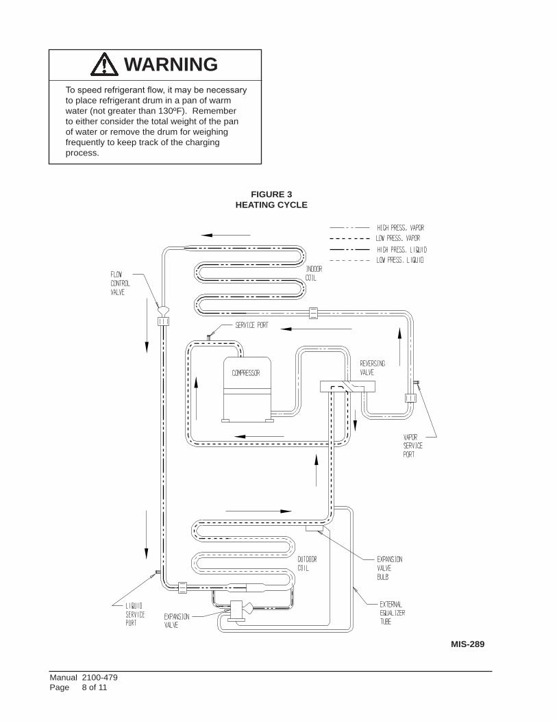
FIGURE 3HEATING CYCLE
WARNING To speed refrigerant flow, it may be necessary to place refrigerant drum in a pan of warm water (not greater than 130ºF). Remember to either consider the total weight of the pan of water or remove the drum for weighing frequently to keep track of the charging process.
MIS-289
Manual 2100-479Page 9 of 11
TroubleshooTing The Mechanical sysTeM
HEAT PUMP — HEATING
LOW SUCTION — LOW HEAD PRESSURE1. Restrictedairflowthroughoutdoorcoil.(Restrictedwater
flowthroughwatercoil.)
2. Defective outdoor motor. (Defective water pump.)
3. Low outdoor air temperature. (Low water temperature.)
4. Frozen outdoor coil. (Frozen water coil.)
5. Restricted liquid line, dryer, metering device, etc.
6. Low charge.
7. Low indoor air temperature.
HIGH SUCTION — LOW HEAD PRESSURE1. Defective or broken valves.
2. IPR valve open.
3. Defective reversing valve.
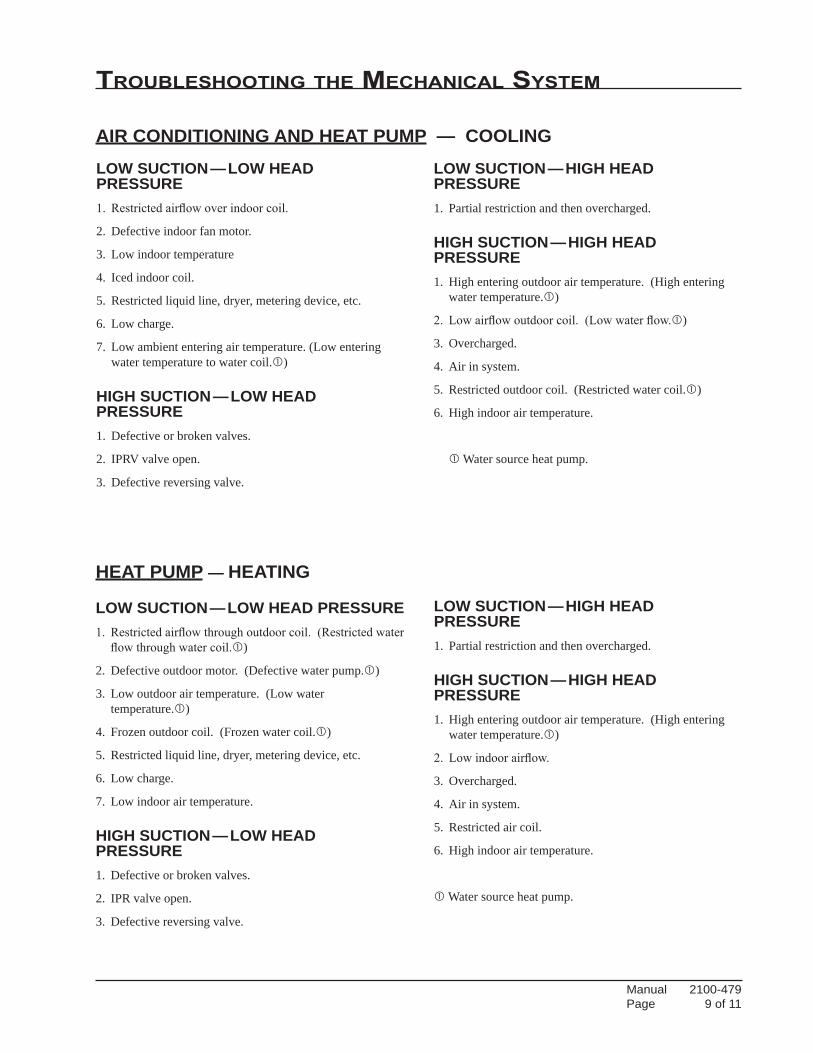
LOW SUCTION — LOW HEAD PRESSURE1. Restrictedairflowoverindoorcoil.
2. Defective indoor fan motor.
3. Low indoor temperature
4. Iced indoor coil.
5. Restricted liquid line, dryer, metering device, etc.
6. Low charge.
7. Low ambient entering air temperature. (Low entering water temperature to water coil.)
HIGH SUCTION — LOW HEAD PRESSURE1. Defective or broken valves.
2. IPRV valve open.
3. Defective reversing valve.
AIR CONDITIONING AND HEAT PUMP — COOLING
LOW SUCTION — HIGH HEAD PRESSURE1. Partial restriction and then overcharged.
HIGH SUCTION — HIGH HEAD PRESSURE1. High entering outdoor air temperature. (High entering
water temperature.)
2. Lowairflowoutdoorcoil.(Lowwaterflow.)
3. Overcharged.
4. Air in system.
5. Restricted outdoor coil. (Restricted water coil.)
6. High indoor air temperature.
Water source heat pump.
LOW SUCTION — HIGH HEAD PRESSURE1. Partial restriction and then overcharged.
HIGH SUCTION — HIGH HEAD PRESSURE1. High entering outdoor air temperature. (High entering
water temperature.)
2. Lowindoorairflow.
3. Overcharged.
4. Air in system.
5. Restricted air coil.
6. High indoor air temperature.
Water source heat pump.
Manual 2100-479Page 10 of 11Manual 2100-479Page 10 of 11
ylppuSre
woP
metsySfo
ediS
erusserP
hgiH
ediS
woLlarene
G
ediS
eniLotrete
Mrotcatno
Cforotcatno
Cfoedi
SdaoL
lanimreTroto
Mot
tiucriClortno
Csroto
Mrosserp
moC
noitarepO
metsyS
riAresnedno
Cri
ArotaropavE
dnarosserpmo
Croto
mnafresnednoc
tratstonlliw
tubtratstonlliwrosserp
moC
nafresnednocnurlli
w
rotom
nafresnednoC
tratstonlliw
tub"s
muh"rosserpmo
Ctratstonlli
w
daolrevono
selcycrosserpmo
C
selcyctrohsrosserpmo
Cerusserp
wolno
on—ylsuounitnoc
snurrosserpmo
Cgnilooc
ylsuounitnocsnurrosserp
moC
gnilooc—
ysionrosserpmo
C
liosesolrosserp
moC
hgihoot
erusserpdae
H
woloot
erusserpdae
H
gnitaewsro
gnitsorfenil
diuqiL
erusserpnoitcu
Shgih
oot
woloot
erusserpnoitcu
S
gnitsorfrotaropavE
gnitaewsro
gnitsorfenil
noitcuS
lliwre
wolbrotaropavE
tratston
rotcatnocsnurroto
mnafresnedno
Cni
dellupton
otkcab
gnidoolftnaregirferdiuqiL
—rosserpmoc
metsysebut
pac
erutarepmet
ecapShgih
oot
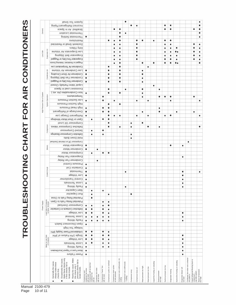
Power FailureBlown Fuses or Tripped Circuit Breakers
Faulty WiringLoose TerminalsLow VoltageSingle 1PH Failure of 3PHUnbalanced Power Supply 3PHVoltage Too HighOpen Disconnect SwitchFaulty WiringLoose TerminalLow VoltageDefective Contacts in ContactorCompressor OverloadPotential Relay Fails to OpenPotential Relay Fails to CloseRun CapacitorStart CapacitorFaulty WiringLoose TerminalsControl TransformerLow VoltageThermostatContactor CoilPressure ControlCondenser Fan RelayEvaporator Fan RelayCompressor MotorCondenser MotorEvaporator MotorCompressor Off on Internal Overload
Hold Down BoltsDefective Compressor BearingsSeized CompressorDefective Compressor ValvesCompressor Oil LevelOpen or Short Motor WindingsRefrigerant Charge LowOvercharge of RefrigerantHigh Head PressureHigh Suction PressureLow Suction PressureTemperaturesNon-Condensables (Air, etc.)Excessive Load in SpaceLiquid Valve Partially ClosedCondenser Fins Dirty or PluggedCondenser Fan Belt SlippingCondenser Air Short CircuitingLow Condenser Air VolumeCondenser Air Temperature LowPlugged or Restricted Metering Device
Evaporator Fins Dirty or PluggedEvaporator Belt SlippingLow Evaporator Air VolumeDirty FiltersDuctwork Small or RestrictedRestrictionsThermostat SettingThermostat LocationStratified Air in SpaceIncorrect Refrigerant PipingSystem Too Small
Gen
eral
ly th
e ca
use.
Alw
ays
mak
e th
ese
chec
ks fi
rst.
Occ
asio
nally
the
caus
e.M
ake
thes
e ch
ecks
onl
yif
first
che
cks
fail
tolo
cate
trou
ble.
Rar
ely
the
caus
e. M
ake
this
che
ck o
nly
ifpr
evio
us c
heck
s fa
il to
loca
te tr
oubl
e.
TR
OU
BL
ES
HO
OT
ING
CH
AR
T F
OR
AIR
CO
ND
ITIO
NE
RS

Manual 2100-479Page 11 of 11Manual 2100-479Page 11 of 11
ylppuSre
woP
noitceSroodtu
Onoitce
SroodnItae
H.xuA
egatloVeniL
tiucriClortno
Crosserp
moC
metsyStnaregirfe
Rtsorfe
Dlortno
C.ve
RevlaV
kcehC
evlaVnaFroodtu
Olio
Cdnaroto
Mre
wolBroodnI
lioC
dnarotoM
kcehC
rotom
naf.D.
Odnarosserp
moC
etarepotonod
nurtonlliwrosserp
moC
snurrotom
naf.D.
O
tub"s
muh"rosserpmo
Ctratstonlli
w
daolrevono
selcycrosserpmo
C
hgihnofforosserp
moC
lortnocerusserp
ysionrosserpmo
C
hgihoot
erusserpdae
H
woloot
erusserpdae
H
erusserpnoitcu
Shgih
oot
woloot
erusserpnoitcu
S
tratstonlliwre
wolb.D.I
-gnicirognitsorflioc.
D.I
spmarosserp
mochgi
H
snurrosserpmo
Cgnilooc
on—ylsuounitnoc
gnidoolftnaregirferdiuqiL
rosserpmoc
otkcab
snurrosserpmo
Cgnitaeh
on—ylsuounitnoc
liocno
ecion
setaitinielcyctsorfe
D
seodevlav
gnisreveR
tfihston
traprewol
nopu
dliubecI
lioc.D.
Ofo
gnidoolftnaregirferdiuqiL
rosserpmoc
otkcab
.D.I
notaehyrailixu
Affore
wolb
stsocgnitarepo
evissecxE
noeci
evissecxE
lioc.D.
O
TR
OU
BL
ES
HO
OT
ING
CH
AR
T F
OR
AIR
TO
AIR
HE
AT
PU
MP
S
Power FailureBlown Fuse or Tripped BreakerFaulty WiringLoose TerminalsLow VoltageSingle 1PH Failure of 3PHUnbalanced 3PHDefective Contacts in ContactorCompressor OverloadPotential RelayRun CapacitorStart CapacitorFaulty WiringLoose TerminalsControl TransformerLow VoltageThermostatContactor CoilPressure Control or Impedance RelayIndoor Fan RelayDischarge Line Hitting Inside of Shell
Bearings DefectiveSeizedValve DefectiveMotor Windings DefectiveRefrigerant Charge LowRefrigerant OverchargeHigh Head PressureLow Head PressureHigh Suction PressureLow Suction PressureNon-CondensablesUnequalized PressuresSensing Bulb Loose-Poorly Located
Cycle Too Long (Clock timer)Defective Control, Timer or RelayLeakingDefective Valve or CoilSticking ClosedLeaking or DefectivePlugged or Restricted Meter Device (Htg)
Fins Dirty or PluggedMotor Winding DefectiveRecirculation or AirAir Volume Low (Cooling)Low Temperature Coil Air (Cooling)Plugged or Restricted Metering Device (Clg)
Fins Dirty or PluggedMotor Winding DefectiveAir Volume LowAir Filters DirtyUndersized or Restricted DuctworkSticking ClosedLeaking or DefectiveAuxiliary Heat Upstream of Coil
Den
otes
com
mon
caus
e.
Den
otes
occa
sion
alca
use.
CoolingCycleHeating or Cooling Cycles Heating Cycle


Page 1 of 70
MIS-2957 A
I-TEC® Series Packaged Heat Pump
Models:
INSTALLATION INSTRUCTIONS
Bard Manufacturing Company, Inc. Bryan, Ohio 43506
www.bardhvac.com
Manual: 2100-549ZSupersedes: 2100-549Y Date: 10-21-21
I30H1-AI30H1-BI30H1-C
I36H1-AI36H1-BI36H1-C
I42H1-AI42H1-BI42H1-C
I48H1-AI48H1-BI48H1-C
I60H1-AI60H1-BI60H1-C
I30H1DAI30H1DBI30H1DC
I36H1DAI36H1DBI36H1DC
I42H1DAI42H1DBI42H1DC
I48H1DAI48H1DBI48H1DC
I60H1DAI60H1DBI60H1DC

Manual 2100-549ZPage 2 of 70
CONTENTS
Getting Other Information and Publications .........4 General ...................................................................5 ANSI Z535.5 Definitions ...........................................5
I-TEC Series General Information .............................6 I-TEC Model Nomenclature .......................................6 Shipping Damage .....................................................9 Unit Removal from Skid ............................................9 Handling Unit After Removal from Skid ......................9 Required Steps After Final Placement ......................10 Minimum Installation Height ...................................10 Securing Unit to Structure ......................................10 Seismic Considerations ...........................................10 Duct Work..............................................................18 Filters ...................................................................18 Condensate Drain ...................................................19
Installation ..................................................................22 Mounting the Unit ..................................................22 Wiring – Main Power ...............................................22 Wiring – Low Voltage Wiring .....................................22 Low Voltage Connections .........................................23 General .................................................................23
Start Up ........................................................................31 General .................................................................31 Topping Off System Charge .....................................31 Safety Practices .....................................................31 Description of Standard Equipment ..........................32 Important Installer Note ..........................................32 Phase Monitor ........................................................32 Three Phase Scroll Compressor Start Up Information .32 Service Hints .........................................................32 Sequence of Operation ............................................33 Pressure Service Ports ............................................33 Lowering Outdoor Fan Speed for Sound ....................33 Defrost Cycle .........................................................33
I-TEC Commercial Room Ventilator System (Vent Code "M") ..........................................................35 General Description ................................................35 Control Wiring ........................................................35 Recommended Control Sequences ...........................35 Setting the Ventilation CFM Levels ...........................35
I-TEC Combination CRV and Economizer Ventilation System (Vent Code "N") ......................38 General Description ................................................38 Control Wiring ........................................................38 Setting the Ventilation CFM Levels ...........................39 I-TEC Economizer Sequence of Operation .................40 Heating Mode Operation .........................................40 Ventilation Mode ...................................................40
I-TEC Modulating Commercial Room Ventilator System (Vent Code "Q") ........................41 General Description ................................................41 Control Wiring ........................................................41 Recommended Control Sequences ...........................41 Changing Ventilation CFM Rates in Manual Mode ......42 Changing to Fully Modulating Mode .........................42 Configuring Bard Part #8403-096 CO2 Control for CRV Modulating Control .....................................46
I-TEC Energy Recovery Ventilator System (Vent Code "R") ...........................................................49 General Description ................................................49 Control Wiring ........................................................49 Recommended Control Sequences ...........................50 Changing Ventilation CFM Rates in Manual Mode ......50 Changing to Fully Modulating Mode .........................50 Configuring Bard Part #8403-096 CO2 Control for ERV Modulating Control .....................................55 Energy Recovery Ventilator Maintenance ....................58
Troubleshooting .........................................................60 Solid State Heat Pump Control ................................60 Checking Temperature Sensor ..................................61 Troubleshooting Condensate Overflow Systems ..........62 Troubleshooting ECM™ 142R Outdoor Fan Motors ....63 Troubleshooting ECM™ Indoor Blower Motors ...........65 Fan Blade Setting Dimensions .................................68 Refrigerant Charge ..................................................68
Manual 2100-549ZPage 3 of 70
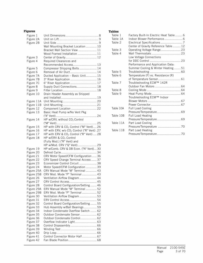
Figures Figure 1 Unit Dimensions .................................... 8 Figure 2A Unit on Lift ........................................... 9 Figure 2B Unit Side .............................................. 9 Wall Mounting Bracket Location ............ 10 Bracket Wall Section View .................... 11 Wood Framed Installation ..................... 11 Figure 3 Center of Gravity .................................. 12 Figure 4 Required Clearances and Recommended Access.......................... 13 Figure 5 Compressor Shipping Bolts ................... 14 Figure 6 Removal of Air Duct ............................. 14 Figure 7A Ducted Application – Basic Unit ............ 15 Figure 7B 3" Riser Application ............................. 16 Figure 7C 6" Riser Application ............................. 17 Figure 8 Supply Duct Connections ...................... 18 Figure 9 Filter Location ..................................... 18 Figure 10 Drain Header Assembly as Shipped and Installed ....................................... 19 Figure 11A Unit Mounting ..................................... 20 Figure 11B Unit Mounting ..................................... 21 Figure 12 Component Location ............................ 22 Figure 13 Basic Heat Pump w/No Vent Pkg ("X" Vent) ............................................. 24 Figure 14 HP w/CRV, without CO2 Control ("M" Vent) ............................................ 25 Figure 15 HP with CRV & CO2 Control ("M" Vent) .... 26 Figure 16 HP with ERV, w/o CO2 Control ("R" Vent) . 27 Figure 17 HP with ERV & CO2 Control ("R" Vent) .... 28 Figure 18 HP w/ERV & CO2 Control (Fully Mod.) ("R" Vent) and HP w/Mod. CRV ("Q" Vent) ..................... 29 Figure 19 HP w/Comb. CRV & DB Econ. ("N" Vent) ... 30 Figure 20 Defrost Cycle ....................................... 34 Figure 21 CRV Motor Speed/CFM Configuration ..... 36 Figure 22 CRV Speed Change Terminal Access ...... 37 Figure 23 Economizer Control Circuit ................... 38 Figure 24 Motor Speed/CFM Configuration ............ 39 Figure 25A CRV Manual Mode "M" Terminal ............ 43 Figure 25B CRV Mod. Mode "P" Terminal ................ 43 Figure 26 Ventilation Airflow Diagram ................... 44 Figure 27 CRV Control Access .............................. 45 Figure 28 Control Board Configuration/Setting ....... 46 Figure 29A ERV Manual Mode "M" Terminal ............ 52 Figure 29B ERV Mod. Mode "P" Terminal ................ 52 Figure 30 Ventilation Airflow Diagram ................... 53 Figure 31 ERV Control Access .............................. 54 Figure 32 Control Board Configuration/Setting ....... 55 Figure 33 Hub Assembly w/Ball Bearings .............. 59 Figure 34 Indoor Condensate Overflow Switch ....... 62 Figure 35 Outdoor Condensate Sensor .................. 62 Figure 36 Outdoor Condensate Control .................. 62 Figure 37 Overflow Indicator Light ........................ 63 Figure 38 Control Disassembly ............................. 66 Figure 39 Winding Test ....................................... 66 Figure 40 Drip Loop ............................................ 66 Figure 41 Control Connector Motor Half ................ 67 Figure 42 Fan Blade Position ............................... 68
Tables Table 1 Factory Built-In Electric Heat Table ........6 Table 1A Indoor Blower Performance ....................6 Table 2 Electrical Specifications ........................7 Center of Gravity Reference Table .........12 Table 3 Operating Voltage Range ......................23 Table 4 Wall Thermostats ................................23 Low Voltage Connections for DDC Control ..................................23 Performance and Application Data: Summer Cooling & Winter Heating ........51 Table 5 Troubleshooting ..................................60 Table 6 Temperature (F) vs. Resistance (R) of Temperature Sensor .........................61 Table 7 Troubleshooting ECM™ 142R Outdoor Fan Motors ............................64 Table 8 Cooling Mode .....................................64 Table 9 Heat Pump Mode ................................64 Troubleshooting ECM™ Indoor Blower Motors ....................................67 Power Connector .................................67 Table 10A Full Load Cooling Pressure/Temperature ..........................69 Table 10B Full Load Heating Pressure/Temperature ..........................69 Table 11A Part Load Cooling Pressure/Temperature .........................70 Table 11B Part Load Heating Pressure/Temperature ..........................70

Manual 2100-549ZPage 4 of 70
GETTING OTHER INFORMATION AND PUBLICATIONS
These publications can help when installing the air conditioner or heat pump. They can usually be found at the local library or purchase them directly from the publisher. Be sure to consult current edition of each standard.
National Electrical Code ..................... ANSI/NFPA 70
Standard for the Installation ............. ANSI/NFPA 90A of Air Conditioning and Ventilating Systems
Standard for Warm Air ......................ANSI/NFPA 90B Heating and Air Conditioning Systems
Load Calculation for ......................ACCA Manual J orWinter and Summer Manual N Air Conditioning
Low Pressure, Low Velocity ............ ACCA Manual D orDuct System Design Manual Q Winter and Summer Air Conditioning
FOR MORE INFORMATION, CONTACT THESE PUBLISHERS:
ACCA Air Conditioning Contractors of America 1712 New Hampshire Avenue Washington, DC 20009 Telephone: (202) 483-9370 Fax: (202) 234-4721
ANSI American National Standards Institute 11 West Street, 13th Floor New York, NY 10036 Telephone: (212) 642-4900 Fax: (212) 302-1286
ASHRAE American Society of Heating, Refrigeration, and Air Conditioning Engineers, Inc. 1791 Tullie Circle, N.E. Atlanta, GA 30329-2305 Telephone: (404) 636-8400 Fax: (404) 321-5478
NFPA National Fire Protection Association Batterymarch Park P.O. Box 9101 Quincy, MA 02269-9901 Telephone: (800) 344-3555 Fax: (617) 984-7057
Manual 2100-549ZPage 5 of 70
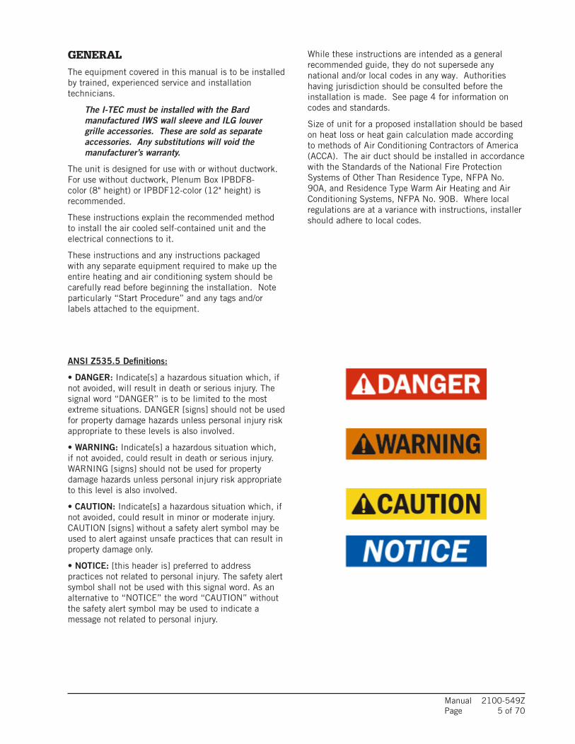
GENERALThe equipment covered in this manual is to be installed by trained, experienced service and installation technicians.
The I-TEC must be installed with the Bard manufactured IWS wall sleeve and ILG louver grille accessories. These are sold as separate accessories. Any substitutions will void the manufacturer’s warranty.
The unit is designed for use with or without ductwork. For use without ductwork, Plenum Box IPBDF8-color (8" height) or IPBDF12-color (12" height) is recommended.
These instructions explain the recommended method to install the air cooled self-contained unit and the electrical connections to it.
These instructions and any instructions packaged with any separate equipment required to make up the entire heating and air conditioning system should be carefully read before beginning the installation. Note particularly “Start Procedure” and any tags and/or labels attached to the equipment.
While these instructions are intended as a general recommended guide, they do not supersede any national and/or local codes in any way. Authorities having jurisdiction should be consulted before the installation is made. See page 4 for information on codes and standards.
Size of unit for a proposed installation should be based on heat loss or heat gain calculation made according to methods of Air Conditioning Contractors of America (ACCA). The air duct should be installed in accordance with the Standards of the National Fire Protection Systems of Other Than Residence Type, NFPA No. 90A, and Residence Type Warm Air Heating and Air Conditioning Systems, NFPA No. 90B. Where local regulations are at a variance with instructions, installer should adhere to local codes.
ANSI Z535.5 Definitions:
• DANGER: Indicate[s] a hazardous situation which, if not avoided, will result in death or serious injury. The signal word “DANGER” is to be limited to the most extreme situations. DANGER [signs] should not be used for property damage hazards unless personal injury risk appropriate to these levels is also involved.
• WARNING: Indicate[s] a hazardous situation which, if not avoided, could result in death or serious injury. WARNING [signs] should not be used for property damage hazards unless personal injury risk appropriate to this level is also involved.
• CAUTION: Indicate[s] a hazardous situation which, if not avoided, could result in minor or moderate injury. CAUTION [signs] without a safety alert symbol may be used to alert against unsafe practices that can result in property damage only.
• NOTICE: [this header is] preferred to address practices not related to personal injury. The safety alert symbol shall not be used with this signal word. As an alternative to “NOTICE” the word “CAUTION” without the safety alert symbol may be used to indicate a message not related to personal injury.
Manual 2100-549ZPage 6 of 70
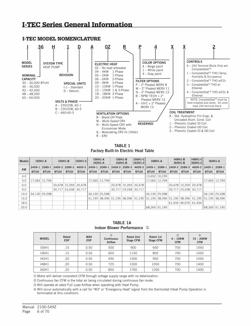
TABLE 1Factory Built-In Electric Heat Table
Models I30H1-A I30H1-B I30H1-C I36H1-AI42H1-A
I36H1-BI42H1-B
I36H1-CI42H1-C I48H1-A I48H1-B
I60H1-BI48H1-CI60H1-C I60H1-A
KW240V-1 208V-1 240V-3 208V-3 460V-3 240V-1 208V-1 240V-3 208V-3 460V-3 240V-1 208V-1 240V-3 208V-3 460V-3 240V-1 208V-1
BTUH BTUH BTUH BTUH BTUH BTUH BTUH BTUH BTUH BTUH BTUH BTUH BTUH BTUH BTUH BTUH BTUH
4.0 13,652 10,239
5.0 17,065 12,799 17,065 12,799 17,065 12,799 17,065 12,799
6.0 20,478 15,359 20,478 20,478 15,359 20,478 20,478 15,359 20,478
9.0 30,717 23,038 30,717 30,717 23,038 30,717 30,717 23,038 30,717
10.0 34,130 25,598 34,130 25,598 34,130 25,598 34,130 25,598
15.0 51,195 38,396 51,195 38,396 51,195 51,195 38,396 51,195 38,396 51,195 51,195 38,396
18.0 61,434 46,076 61,434
20.0 68,260 51,195 68,260 51,195
I-TEC Series General Information
I-TEC MODEL NOMENCLATURE
I 36 H 1 D A 0Z R P 4 X X 2
SPECIAL UNITS(–) – StandardD – Dehum.
REVISION
VOLTS & PHASEA – 230/208, 60-1B – 230/208, 60-3C – 460-60-3 COIL TREATMENT
X – Std. Hydrophilic Fin Evap. & Uncoated Alum. Cond. Coil1 – Phenolic Coated ID Coil2 – Phenolic Coated OD Coil3 – Phenolic Coated ID & OD Coil
CONTROLSX – 24V Terminal Block Only w/o CompleteStatTM
1 – CompleteStatTM THO (Temp, Humidity & Occupancy)2 – CompleteStatTM THO w/CO2
3 – CompleteStatTM THO w/ Ethernet4 – CompleteStatTM THO w/CO2 & Ethernet
MODELSERIES
NOMINAL CAPACITY30 – 30,000 BTUH36 – 36,00042 – 42,00048 – 48,00060 – 60,000
ELECTRIC HEAT0Z – No heat w/breaker04 – 4KW 1-Phase05 – 5KW 1-Phase06 – 6KW 3-Phase09 – 9KW 3-Phase10 – 10KW 1-Phase15 – 15KW 1 & 3-Phase18 – 18KW 3-Phase20 – 20KW 1-Phase
VENTILATION OPTIONSB – Blank-Off PlateM – Multi-Speed CRVN – Multi-Speed CRV with Economizer ModeQ – Modulating CRV (0-10Vdc)R – ERV
FILTER OPTIONSP – 2" Pleated MERV 8M – 2" Pleated MERV 11N – 2" Pleated MERV 13B – NPBI TECH + 2"
Pleated MERV 13A – UV-C + 2" Pleated
MERV 13
COLOR OPTIONSX – Beige paint1 – White paint4 – Gray paint
SYSTEM TYPE HEAT PUMP
RESERVED
NOTE: CompleteStatTM must be field-installed and wired. All units
have 24V terminal block.
Motor will deliver consistent CFM through voltage supply range with no deterioration.Continuous fan CFM is the total air being circulated during continuous fan mode.Will operate at rated Full Load Airflow when operating with Heat Pump.Will occur automatically with a call for "W3" or "Emergency Heat" signal from the thermostat (Heat Pump Operation is terminated at this condition).
TABLE 1A Indoor Blower Performance
MODEL RatedESP
MAXESP
Continuous
Airflow
Rated 2nd Stage CFM
Rated 1st Stage CFM
4 – 10KW
CFM
15 – 20KW
CFM
I30H1 .15 0.50 500 900 650 700 1050
I36H1 .15 0.50 600 1150 850 700 1050
I42H1 .20 0.50 650 1300 950 700 1050
I48H1 .20 0.50 725 1500 1050 700 1400
I60H1 .20 0.50 850 1700 1200 700 1400
Manual 2100-549ZPage 7 of 70
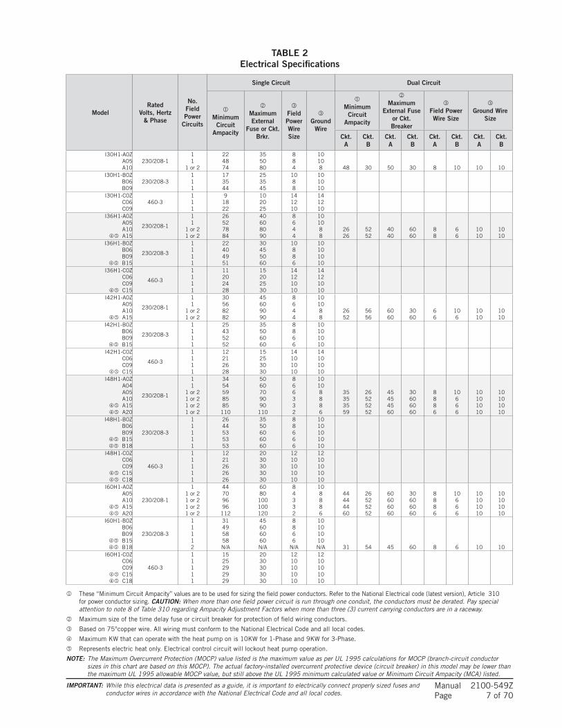
TABLE 2Electrical Specifications
ModelRated
Volts, Hertz & Phase
No. Field Power
Circuits
Single Circuit Dual Circuit
Minimum
Circuit Ampacity
Maximum External
Fuse or Ckt. Brkr.
Field Power Wire Size
Ground
Wire
Minimum
CircuitAmpacity
Maximum
External Fuse or Ckt. Breaker
Field Power Wire Size
Ground Wire
Size
Ckt. A
Ckt. B
Ckt. A
Ckt. B
Ckt. A
Ckt. B
Ckt. A
Ckt. B
I30H1-A0ZA05A10
230/208-111
1 or 2
224874
355080
884
10108 48 30 50 30 8 10 10 10
I30H1-B0ZB06B09
230/208-3111
173544
253545
1088
101010
I30H1-C0ZC06C09
460-3111
91822
102025
141210
141210
I36H1-A0ZA05A10
A15
230/208-1
11
1 or 21 or 2
26527884
40608090
8644
101088
2626
5252
4040
6060
88
66
1010
1010
I36H1-B0ZB06B09
B15
230/208-3
1111
22404951
30455060
10886
10101010
I36H1-C0ZC06C09
C15
460-3
1111
11202428
15202530
14121010
14121010
I42H1-A0ZA05A10
A15
230/208-1
11
1 or 21 or 2
30568282
45609090
8644
101088
2652
5656
6060
3060
66
106
1010
1010
I42H1-B0ZB06B09
B15
230/208-3
1111
25435252
35506060
8866
10101010
I42H1-C0ZC06C09
C15
460-3
1111
12212628
15253030
14101010
14101010
I48H1-A0ZA04A05A10
A15 A20
230/208-1
11
1 or 21 or 21 or 21 or 2
3454598585
110
5060709090
110
866332
10108886
35353559
26525252
45454560
30606060
8886
10666
10101010
10101010
I48H1-B0ZB06B09
B15 B18
230/208-3
11111
2644535353
3550606060
88666
1010101010
I48H1-C0ZC06C09
C15 C18
460-3
11111
1221262626
2030303030
1210101010
1210101010
I60H1-A0ZA05A10
A15 A20
230/208-1
11 or 21 or 21 or 21 or 2
44709696
112
6080
100100120
84332
108886
44444460
26525252
60606060
30606060
8886
10666
10101010
10101010
I60H1-B0ZB06B09
B15 B18
230/208-3
11112
31495858N/A
45606060N/A
8866
N/A
10101010N/A 31 54 45 60 8 6 10 10
I60H1-C0ZC06C09
C15 C18
460-3
11111
1525292929
2030303030
1210101010
1210101010
These “Minimum Circuit Ampacity” values are to be used for sizing the field power conductors. Refer to the National Electrical code (latest version), Article 310 for power conductor sizing. CAUTION: When more than one field power circuit is run through one conduit, the conductors must be derated. Pay special attention to note 8 of Table 310 regarding Ampacity Adjustment Factors when more than three (3) current carrying conductors are in a raceway.
Maximum size of the time delay fuse or circuit breaker for protection of field wiring conductors.
Based on 75°copper wire. All wiring must conform to the National Electrical Code and all local codes.
Maximum KW that can operate with the heat pump on is 10KW for 1-Phase and 9KW for 3-Phase.
Represents electric heat only. Electrical control circuit will lockout heat pump operation.
NOTE: The Maximum Overcurrent Protection (MOCP) value listed is the maximum value as per UL 1995 calculations for MOCP (branch-circuit conductor sizes in this chart are based on this MOCP). The actual factory-installed overcurrent protective device (circuit breaker) in this model may be lower than the maximum UL 1995 allowable MOCP value, but still above the UL 1995 minimum calculated value or Minimum Circuit Ampacity (MCA) listed.
IMPORTANT: While this electrical data is presented as a guide, it is important to electrically connect properly sized fuses and conductor wires in accordance with the National Electrical Code and all local codes.
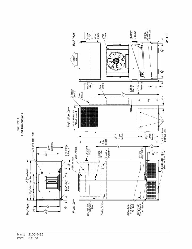
Manual 2100-549ZPage 8 of 70
33 4"
241 2"
221 4"
Lowe
rSe
ction
713 4"
Uppe
rSe
ction
Supp
lyAi
r
Retur
nAi
rRe
turn
Air
Inner
Slee
ve
Outer
Slee
ve
Outer
Slee
ve
Inner
Slee
ve
UnitD
rain
(2)O
pt.
Entra
nces
Uni
t Spe
cific
atio
n S
heet
Top
Vie
w
Fron
tVie
w
Rig
htS
ide
Vie
w
MIS-
3831
(2) S
ideHa
ndles
Bac
kV
iew
Retur
n Air
Filter
s
(4)L
ift-Of
fHi
nges
AirF
ilters
Vent
Exha
ust
(2)1
2"x2
0"
AirF
ilters
Vent
Intak
e(2
)Was
hable
Contr
ol Pa
nel
Elec
tricHe
at Wire
Chan
nel
Disc
onne
ctEl
ectric
al
Door
Latch
Lock
ing
Door
Latch
Lock
ing
(2)2
"x24
"x30
"
Fron
tFor
kliftH
oles
(Rem
oveF
ront
Trim
)4
58" " 8
155
"13
1
94"
Total
Heigh
t
Open
ings
(2)R
eturn
Side
Forkl
iftHo
les(R
emov
e Side
s)
2" 71
1
30"W
ithDo
orsa
ndSi
desR
emov
ed
Entra
nce
Entra
nce
High
Volt
age
Low
Volta
ge
20"x
24" S
upply
Fram
e
1 2
4"
Total
Depth"3 8
" 426
3
"2"
20"
811
7
" 411
1
"Tota
lWidt
h8
31
547
24"
"1 4 " 428
1 346
1 8"W
ith S
idesR
emov
ed
Rear
Colle
ctor
Asse
mbly
(4)U
NIT
DRAI
NS
8"
31 8"31 8"
FIG
UR
E 1
Uni
t D
imen
sion
s
Manual 2100-549ZPage 9 of 70
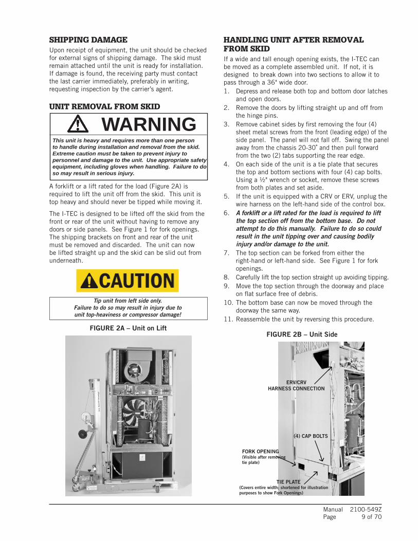
SHIPPING DAMAGEUpon receipt of equipment, the unit should be checked for external signs of shipping damage. The skid must remain attached until the unit is ready for installation. If damage is found, the receiving party must contact the last carrier immediately, preferably in writing, requesting inspection by the carrier’s agent.
UNIT REMOVAL FROM SKID
HANDLING UNIT AFTER REMOVAL FROM SKIDIf a wide and tall enough opening exists, the I-TEC can be moved as a complete assembled unit. If not, it is designed to break down into two sections to allow it to pass through a 36" wide door.1. Depress and release both top and bottom door latches
and open doors.2. Remove the doors by lifting straight up and off from
the hinge pins.3. Remove cabinet sides by first removing the four (4)
sheet metal screws from the front (leading edge) of the side panel. The panel will not fall off. Swing the panel away from the chassis 20-30˚ and then pull forward from the two (2) tabs supporting the rear edge.
4. On each side of the unit is a tie plate that secures the top and bottom sections with four (4) cap bolts. Using a ½" wrench or socket, remove these screws from both plates and set aside.
5. If the unit is equipped with a CRV or ERV, unplug the wire harness on the left-hand side of the control box.
6. A forklift or a lift rated for the load is required to lift the top section off from the bottom base. Do not attempt to do this manually. Failure to do so could result in the unit tipping over and causing bodily injury and/or damage to the unit.
7. The top section can be forked from either the right-hand or left-hand side. See Figure 1 for fork openings.
8. Carefully lift the top section straight up avoiding tipping.9. Move the top section through the doorway and place
on flat surface free of debris.10. The bottom base can now be moved through the
doorway the same way.11. Reassemble the unit by reversing this procedure.
FIGURE 2A – Unit on LiftFIGURE 2B – Unit Side
A forklift or a lift rated for the load (Figure 2A) is required to lift the unit off from the skid. This unit is top heavy and should never be tipped while moving it.
The I-TEC is designed to be lifted off the skid from the front or rear of the unit without having to remove any doors or side panels. See Figure 1 for fork openings. The shipping brackets on front and rear of the unit must be removed and discarded. The unit can now be lifted straight up and the skid can be slid out from underneath.
ERV/CRVHARNESS CONNECTION
TIE PLATE(Covers entire width; shortened for illustration purposes to show Fork Openings)
FORK OPENING(Visible after removing tie plate)
(4) CAP BOLTS
WARNINGThis unit is heavy and requires more than one person to handle during installation and removal from the skid. Extreme caution must be taken to prevent injury to personnel and damage to the unit. Use appropriate safety equipment, including gloves when handling. Failure to do so may result in serious injury.
Tip unit from left side only.Failure to do so may result in injury due to unit top-heaviness or compressor damage!

Manual 2100-549ZPage 10 of 70
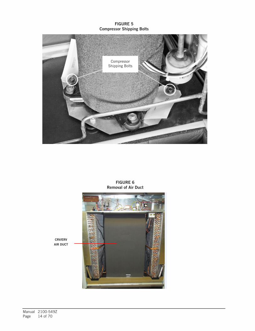
REQUIRED STEPS AFTER FINAL PLACEMENTThe compressor is secured to the base with two (2) bolts for shipping. Although the unit will perform as designed with the shipping bolts in place, there may be a noticeable additional noise and vibration noted. To obtain the lowest noise and vibration levels, remove the shipping bolts after the unit is in its final operating location. To gain access to the compressor, the compressor access panel must be removed (Figure 9). Once this panel is removed, the CRV/ERV air duct must be removed (see Figure 6).
The air duct is removed by pulling it straight out; there are no screws securing it in place. Both the top and bottom slide at the same time (pull hard). Once removed, the compressor is visible as well as the tags on the shipping bolts (Figure 5).
After the compressor shipping bolts have been removed, the CRV/ERV air duct can be slid back in place and the compressor access panel attached.
MINIMUM INSTALLATION HEIGHTThe minimum installation height to the bottom of the roof or fixed ceiling for ducted applications is 9' 7". This provides enough clearance to install the duct work. See Figure 7A.
The IWS Series wall sleeve has a built-in vertical adjustment to fit window sill heights from 31-34". If additional height is required, two riser platform accessories are available. The IRP3 increases the unit height by 3" (Figure 7B) and the IRP6 by 6" (Figure 7C).
Several construction options are available for unit installation of the IZ Series. Serviceability and filter
access must be considered before installing. See Figure 5D for required clearances and recommended service access dimensions.
SECURING UNIT TO STRUCTUREShipped with the I-TEC unit is a wall mounting bracket (screwed to shipping skid on backside of unit). This bracket can be utilized to secure the top portion of the unit to the wall using the appropriate field-supplied hardware based upon the material being fastened to. (There are several offset holes, sized to accept up to a 1/4" diameter fastener, that will easily allow studs to be hit on a framed wall.) See Bracket Wall Section View for locating this top wall bracket which will need to be applied after the unit is located in the final position.
Additional/optional mounting holes for up to a 3/8" diameter fastener are also available in the backside of the unit. These can be accessed by:
• removing the air filters for the uppermost set
• removing the compressor section service door for the lower set
Refer to Wood Framed Installation for additional framing required to secure unit to wall.
The additional/optional mounting holes will require a long extension to drive the fasteners.
SEISMIC CONSIDERATIONSThe I-TEC product features several locations for product securement but all site conditions are different. Consult with a licensed Seismic Engineer to advise of particular needs when attaching the I-TEC unit to the structure.
Wall Mounting Bracket Location
MIS-3029
2"1 11/16" 43 3/8"
Ø1/4"
94" FROM BOTTOMOF BRACKET TOFLOOR WITHOUT
RISER KIT
7/8"
3/4"1 1/2"
BRACKET

Manual 2100-549ZPage 11 of 70
7 3/818 3/435"
17.5"
CL
Right Side ViewFront (Wall Only) View
Wall Section View
MIS-2918 D
CL
RISER KIT DIM A DIM B DIM CNONE 31"-34" MAX 29 17/32" 94 1/8"
IRP-3 (3") 34"-37" MAX 32 17/32" 97 1/8"IRP-6 (6") 37"-40" MAX 35 17/32" 100 1/8"
Outside
Grille
Telescoping
Floor
Unit
Optional
Wall Sleeve**
Duct
Ceiling Wall
OptionalTrim or
Supply DuctBox
31" Min.34" Max.
Mounting holes(4) optional Unit
OpeningCentered on
* Higher Sill Heights Acheivable With Base Kit.
*
** Separate telescoping sleeves available for different wall thicknesses.
*
Bracket
Wall
Optional Top
Outside
Room Floor Level
(4) optional UnitMounting holes
Sleeve MountingHole Locations
FLOOR MOUNTING HOLE& CENTERLINES
7 "20 8
"
DIM B
8"
256 1
"8"
6"
820 7
20 78 "
15
DIM A
48-1/2" Max.48" Min.
1
3"
"849 3
Centered
"8
Centered
43-1/4" Max.20"42-3/4" Min.
"
743
20"
20"20"
"1116
16
DIM C
4
43 38 "
6.00
41.75
20.88
29.568.00
8.0036.88
56.50
*
riser kit. If unit uses riser kit addappropriate dimension to height.
* Height dimension shown withoutFloor
Unit
Inner wall
(4) lower fastenerholes
(4) Upperfastener holes
MIS-3072
Bracket Wall Section View
Wood Framed Installation (for Wall Attachment)
Manual 2100-549ZPage 12 of 70
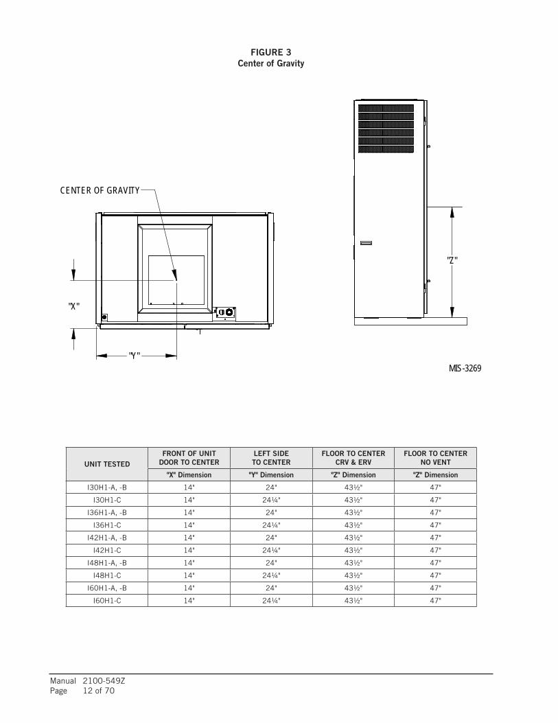
FIGURE 3Center of Gravity
"Y"
"X"
"Z"
MIS-3269
CENTER OF GRAVITY
UNIT TESTEDFRONT OF UNIT
DOOR TO CENTERLEFT SIDETO CENTER
FLOOR TO CENTERCRV & ERV
FLOOR TO CENTERNO VENT
"X" Dimension "Y" Dimension "Z" Dimension "Z" Dimension
I30H1-A, -B 14" 24" 43½" 47"
I30H1-C 14" 24¼" 43½" 47"
I36H1-A, -B 14" 24" 43½" 47"
I36H1-C 14" 24¼" 43½" 47"
I42H1-A, -B 14" 24" 43½" 47"
I42H1-C 14" 24¼" 43½" 47"
I48H1-A, -B 14" 24" 43½" 47"
I48H1-C 14" 24¼" 43½" 47"
I60H1-A, -B 14" 24" 43½" 47"
I60H1-C 14" 24¼" 43½" 47"

Manual 2100-549ZPage 13 of 70
FIGURE 4 Required Clearances and Recommended Access
12" MIN.FOR RIGHT
SIDEACCESS
12" MIN.FOR LEFT
SIDEACCESS
12" MIN. 12" MIN.
12" MIN. 12" MIN.
0" REQUIRED12" RECOMENDED
0" REQUIRED12" RECOMENDED
48" MIN.
31 3/8"
12" MIN.12" MIN.
48"MIN. FOR
FILTER ACCESS
24" MIN. 24" MIN.
MIS-3273
RECOMMENDED SERVICE
WING WALL CONSTRUCTION TOP VIEW
CLOSET CONSTRUCTION TOP VIEW
LEFT CORNER CONSTRUCTION TOP VIEW
FILTERS
RIGHT CORNER CONSTRUCTION TOP VIEW
ACCESS DIMENSIONS
REMOVABLESIDES 1
1 ALL FILTER AND COMPONENTACCESS IS FROM THE FRONT.COILS CAN BE CLEANED FROMTHE FRONT, BUT SIDES AREEASILY REMOVED FOR ENHANCEDACCESS.
IMPORTANTUnit can be located in corner with 0" clearance as long as other side is unobstructed
Manual 2100-549ZPage 14 of 70
COMPRESSOR SHIPPING BOLT
COMPRESSOR SHIPPING BOLT
CRV/ERV
AIR DUCT
Compressor Shipping Bolts
FIGURE 5 Compressor Shipping Bolts
FIGURE 6 Removal of Air Duct

Manual 2100-549ZPage 15 of 70
9'-2"
MINI
MUM
REQU
IRED
INST
ALLA
TION
HEIG
HT
CLEA
RANC
ERE
COMM
ENDE
D TO
BOTT
OM O
F RO
OF
9'-7"
MIN
IMUM
OR F
IXED
CEI
LING
FLOO
R
OR F
IXED
CEI
LING
BOTT
OM O
F RO
OF
SUSP
ENDE
DCE
ILING
20"
MINI
MUM
7'-9 3
/4"UN
IT H
EIGH
T
FIEL
DSU
PPLIE
D DU
CT
TURN
ING
VANE
SRE
COMM
ENDE
D
MINI
MUM
12"
4" M
INIM
UM F
ROM
TOP
OF U
NIT
TODU
CTBO
TTOM
MIS-
2958
B
FIGURE 7A Ducted Application – Basic Unit

Manual 2100-549ZPage 16 of 70
9'-5"
MINI
MUM
REQU
IRED
INST
ALLA
TION
HEIG
HT
CLEA
RANC
ERE
COMM
ENDE
DTO
BOTT
OMOF
ROOF
9'-10
" MIN
IMUM
ORFI
XED
CEILI
NG
3"RI
SER
FIEL
DSU
PPLIE
DDU
CTTU
RNIN
GVA
NES
RECO
MMEN
DED
12"
MINI
MUM
4" M
INIM
UMFR
OMTO
POF
UNIT
TODU
CTBO
TTOM
MIS-
2989
B
FLOO
R
ORFI
XED
CEILI
NGBO
TTOM
OFRO
OF
SUSP
ENDE
DCE
ILING
MINI
MUM
20"
7'-93
/4"UN
ITHE
IGHT
FIGURE 7B 3" Riser Application

Manual 2100-549ZPage 17 of 70
10'-1
" MIN
IMUM
CL
EARA
NCE
RECO
MMEN
DED
TOBO
TTOM
OF
ROOF
OR F
IXED
CEI
LING
6" R
ISER
9'-8"
MINI
MUM
REQU
IRED
INST
ALLA
TION
HEIG
HT
BOTT
OM O
F RO
OF
FLOO
R
OR F
IXED
CEI
LING
SUSP
ENDE
DCE
ILING
MINI
MUM
20"
7'-9 3
/4"UN
IT H
EIGH
T
FIEL
DSU
PPLIE
D DU
CT
MIS-
2988
B
TURN
ING
VANE
SRE
COMM
ENDE
D
12"
MINI
MUM
4" M
INIM
UM F
ROM
TOP
OF U
NIT
TODU
CTBO
TTOM
FIGURE 7C 6" Riser Application
Manual 2100-549ZPage 18 of 70
DUCT WORKAny heat pump is more critical of proper operating charge and an adequate duct system than a straight air conditioning unit. All duct work must be properly sized for the design airflow requirement of the equipment. Air Conditioning Contractors of America (ACCA) is an excellent guide to proper sizing. All duct work or portions thereof not in the conditioned space should be properly insulated in order to both conserve energy and prevent condensation or moisture damage. When duct runs through unheated spaces, it should be insulated with a minimum of 1" of insulation. Use insulation with a vapor barrier on the outside of the insulation. Flexible joints should be used to connect the duct work to the equipment in order to keep the noise transmission to a minimum.
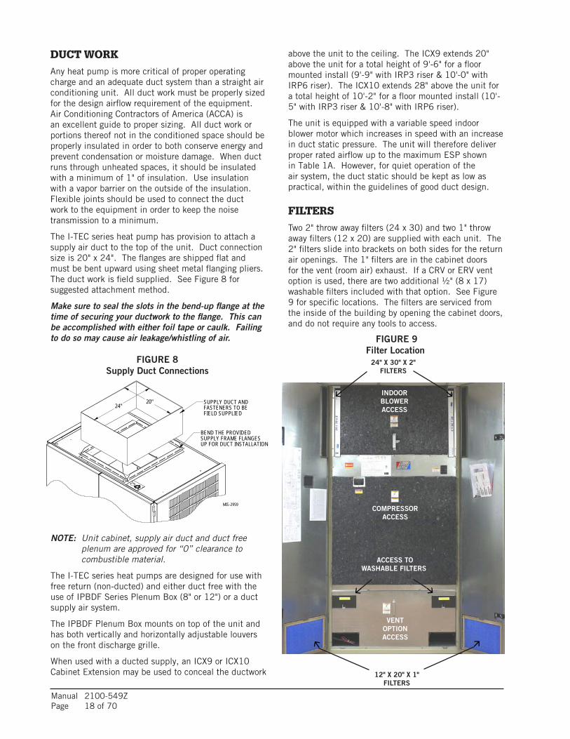
The I-TEC series heat pump has provision to attach a supply air duct to the top of the unit. Duct connection size is 20" x 24". The flanges are shipped flat and must be bent upward using sheet metal flanging pliers. The duct work is field supplied. See Figure 8 for suggested attachment method.
Make sure to seal the slots in the bend-up flange at the time of securing your ductwork to the flange. This can be accomplished with either foil tape or caulk. Failing to do so may cause air leakage/whistling of air.
NOTE: Unit cabinet, supply air duct and duct free plenum are approved for “0” clearance to combustible material.
The I-TEC series heat pumps are designed for use with free return (non-ducted) and either duct free with the use of IPBDF Series Plenum Box (8" or 12") or a duct supply air system.
The IPBDF Plenum Box mounts on top of the unit and has both vertically and horizontally adjustable louvers on the front discharge grille.
When used with a ducted supply, an ICX9 or ICX10 Cabinet Extension may be used to conceal the ductwork
above the unit to the ceiling. The ICX9 extends 20" above the unit for a total height of 9'-6" for a floor mounted install (9'-9" with IRP3 riser & 10'-0" with IRP6 riser). The ICX10 extends 28" above the unit for a total height of 10'-2" for a floor mounted install (10'-5" with IRP3 riser & 10'-8" with IRP6 riser).
The unit is equipped with a variable speed indoor blower motor which increases in speed with an increase in duct static pressure. The unit will therefore deliver proper rated airflow up to the maximum ESP shown in Table 1A. However, for quiet operation of the air system, the duct static should be kept as low as practical, within the guidelines of good duct design.
FILTERSTwo 2" throw away filters (24 x 30) and two 1" throw away filters (12 x 20) are supplied with each unit. The 2" filters slide into brackets on both sides for the return air openings. The 1" filters are in the cabinet doors for the vent (room air) exhaust. If a CRV or ERV vent option is used, there are two additional ½" (8 x 17) washable filters included with that option. See Figure 9 for specific locations. The filters are serviced from the inside of the building by opening the cabinet doors, and do not require any tools to access.
12" X 20" X 1" FILTERS
24" X 30" X 2" FILTERS
ACCESS TO WASHABLE
FILTERS
COMPRESSOR ACCESS
INDOORBLOWERACCESS
VENTOPTIONACCESS
MIS-2959
SUPPLY DUCT ANDFASTENERS TO BEFIELD SUPPLIED
24"20"
BEND THE PROVIDEDSUPPLY FRAME FLANGESUP FOR DUCT INSTALLATION
ACCESS TO WASHABLE FILTERS
COMPRESSOR ACCESS
INDOORBLOWERACCESS
VENTOPTIONACCESS
FIGURE 8 Supply Duct Connections
FIGURE 9 Filter Location

Manual 2100-549ZPage 19 of 70
CONDENSATE DRAINThere are four condensate drain connections from the condenser drain pan (compressor area). These are visible from the rear of the unit. The drain header assembly is field installed and can be found attached to the back of the vent section (see Figure 10). The drain header assembly is to be removed from the vent section and connected to the four drain outlets from the unit. The required hose clamps for the four connections are zip tied to the header assembly.
Access plates are located on the rear of the unit for servicing the drain trap (see Figure 10). If the drain line is to be routed through an unconditioned space, it must be protected from freezing.
The condensate drain line can also be routed back into the unit through either the right-hand or left-hand optional drain locations on the rear of the unit (see Figure 10). The holes are covered by insulation on the inside of the unit and will have to be cut away. Located inside the unit, about 12" in from the front on both the left and right side, are drain holes in the bottom of the base. These holes are covered with insulation and are not visible. They are located very close to the side panels and can be found by pressing down on the insulation. Cut insulation away to expose the hole. A drain trap can now be installed inside of the cabinet, and the drain hose routed directly through the floor.
Once the I-TEC is installed, the rear drains exiting the condenser section can be easily serviced with removal of the pre-painted metal sides (lift-off doors, remove four [4] screws to remove side).
If side access is not available, the drain lines and trap can be serviced by removing either one of the drain access panels on the rear of the unit (in the ventilation package area.)
With No Vent OptionTo access the drain access panels in the rear of this section, simply remove the front door/cover from the box, and the plates are located in the rear of the box.
With Commercial Room Ventilator
1. Open hinged front doors.
2. Disconnect unit power to eliminate shock hazard.
3. Remove front cover/door of CRV vent package. (Can leave filter access panels in place.)
4. Unplug wires coming in on left side from upper unit section.
5. Unplug two wire harness from front (intake) blower.
6. Remove two (2) screws securing front (intake) blower and slide blower out of unit.
7. Remove four (4) screws that retain the partition behind/beneath intake blower removed in Step #6.
8. Rear drain access panels are now visible on both right-hand and left-hand sides in rear of box.
With Energy Recovery Ventilator
To access the rear drain access panels of this section:
1. Open hinged front doors.
2. Disconnect unit power to eliminate shock hazard.
3. Remove front cover/door of ERV vent package. (Can leave filter access panels in place.)
4. Unplug wires coming in on left side from upper unit section.
The unit is shipped from the factory with the drain header disconnected from the unit. This is done to allow for the installer to connect the drain header so that water drains towards the wall drain. The drain header assembly comes assembled with a longer hose on the side that should be installed towards the wall drain (if the room has drains installed).
The drain can be routed directly through the floor or through the wall. There are also two optional drain locations in the lower rear back panel.
The I-TEC design does not require a trap in the condensate disposal tubing. Check local codes to see if a “P” trap is required.
For a stand pipe floor drain or through the wall, there is adequate hose length to reach anything located behind the unit. The lower rear portion of the cabinet is recessed approximately 4" allowing room for a “P” trap to be installed with the cabinet flush with the wall. Keep in mind, the drain line must be able to be removed from the unit if necessary to remove the unit from the wall.
DRAIN OUTLET
WALL/ROOM DRAIN
LONGER HOSEON SIDE WITH
WALL/ROOM DRAIN
DRAIN HEADER ASSEMBLY
TO DRAIN OUTLETSATTACH HEADER
CLAMPS AND
USE PROVIDEDCLAMPS TO SECURE
HEADER TO DRAIN OUTLETS
REMOVE NYLON
INSTALL DRAIN OUTLETON SAME SIDE AS
WALL DRAIN
MIS-3832
FIGURE 10Drain Header Assembly as Shipped and Installed
DRAIN OUTLET
WALL/ROOM DRAIN
LONGER HOSEON SIDE WITH
WALL/ROOM DRAIN
DRAIN HEADER ASSEMBLY
TO DRAIN OUTLETSATTACH HEADER
CLAMPS AND
USE PROVIDEDCLAMPS TO SECURE
HEADER TO DRAIN OUTLETS
REMOVE NYLON
INSTALL DRAIN OUTLETON SAME SIDE AS
WALL DRAIN
MIS-3832
MIS-3832
DRAIN ACCESS LOCATIONS
OPTIONAL UNIT DRAIN ENTRANCES
3/4" PVCDRAIN OUTLET

Manual 2100-549ZPage 20 of 70
DREF.
A AND BREF.
(4) 5/16" - 1/2" NON-TAPPING
REF.E
REF.(6) 5/16" - 3/4" NON-TAPPING C
(4) 1-1/2" LONG SCREWS REF.E
(18) 5/16" - 3/4" SELF TAPPING
B
C
REF.
REF.
REF.A
REF.D
MIS-3014 A
Use (4) 1-1/2" Long
Louver Grille toOuter Sleeve.
Screws to Attach
to Outer Sleeveto Attach Inner SleeveSelf Tapping ScrewsUse (6) 3/4" Long
Unit Fan ShroudExhaust Sleeve to
Screws to AttachUse (6) 3/4" Long
Use (12) 3/4" Long
to Attach Inner Sleeveto Unit Back
Self Tapping Screws
Use (4) 1/2" LongScrews to Attachframe to ExhaustSleeve
Use (12) Field Supplied Concreteor Wood Screws to Secure OuterSleeve to Structure.
outer sleeve.
IMPORTANT!
IMPORTANT! between inner andentire perimeter seam
seal between unit and sleeve.
IMPORTANT!
Doing so may compromise water to not damage gasketing material. Use care when inserting screws
Apply Caulk bead to
Apply liberal amountof caulk to back offlange before installing.
Pull Inner FrameOut Until FlushWith Grille MountingAngle
5. Unplug heat recovery cassette on the side chosen to access, and slide cassette out the front of the unit.
6. Remove two (2) screws securing partition on outboard side of cassette and remove.
7. Rear drain access panels are now visible on both right-hand and left-hand sides in rear of box.
FIGURE 11AUnit Mounting
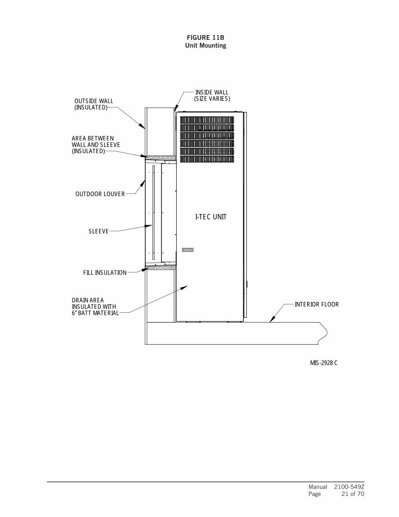
Manual 2100-549ZPage 21 of 70
OUTDOOR LOUVER
SLEEVE
AREA BETWEENWALL AND SLEEVE
(INSULATED)OUTSIDE WALL (SIZE VARIES)
I-TEC UNIT
INTERIOR FLOOR
INSIDE WALL
FILL INSULATION
MIS-2928 C
(INSULATED)
DRAIN AREAINSULATED WITH6" BATT MATERIAL
FIGURE 11BUnit Mounting

Manual 2100-549ZPage 22 of 70
TAP RANGE
240V 253 – 216
208V 220 – 187
INSTALLATION
MOUNTING THE UNITThe wall sleeve is attached to the I-TEC unit from the outside of the building. See Figures 11A & 11B. Refer to wall sleeve manual 2100-562 supplied with sleeve.
Following are the steps for attaching the I-TEC to the wall sleeve.
1. Lift the unit into place making sure that it is aligned side-to-side.
2. Push the unit back until the rear panel touches the sleeve gasket.
3. This unit must be level from side-to-side and from front-to-back. If adjustments are necessary, shim up under the base rails with sheets of metal or any substance not affected by moisture.
4. Attach the sleeve to the unit using the ten (10) ¾" long self-tapping screws supplied with the sleeve.
5. The exhaust sleeve has three (3) ¾" long screw slots in each side flange. Line these up with the screw engagement holes in the fan panel. Attach using six (6) ¾" long pointed sheet metal screws supplied with the sleeve. Extend the sleeve out until it is flush with the louver grill attachment angles.
6. Lock the sleeve in place using two (2) ½" long pointed sheet metal screws on each side by shooting through the slot into a pre-punched hole.
7. A bottom trim piece is shipped loose for installation beneath the doors. Attach the trim piece to the unit with screws provided.
8. The compressor is secured to the base with two (2) bolts for shipping. Both bolts are identified with a tag. Remove shipping bolts (Figure 5).
WIRING – MAIN POWERRefer to the unit rating plate and/or Table 2 for wire sizing information and maximum fuse or circuit breaker size. Each unit is marked with a “Minimum Circuit Ampacity”. This means that the field wiring used must be sized to carry that amount of current. Depending on the installed KW of electric heat, there may be two field power circuits required. If this is the case, the unit serial plate will so indicate. All models are suitable only for connection with copper wire. Each unit and/or wiring diagram will be marked “Use Copper Conductors Only suitable for at least 75°C”. THESE INSTRUCTIONS MUST BE ADHERED TO. Refer to the National Electrical Code (NEC) for complete current carrying capacity data on the various insulation grades of wiring material. All wiring must conform to NEC and all local codes.
The electrical data lists fuse and wire sizes (75°C copper) for all models, including the most commonly used heater sizes. Also shown are the number of field power circuits required for the various models with heaters.
The unit rating plate lists a “Maximum Time Delay Relay" fuse or circuit breaker that is to be used with the equipment. The correct size must be used for proper circuit protection, and also to ensure that there will be no nuisance tripping due to the momentary high starting current of the compressor motor.
See “START UP” section for information on three phase scroll compressor start-ups.
The field wiring conduit connections are located on the top right-hand corner of the unit with a wire raceway to feed the wires down to the circuit breaker(s) (see Figure 12.)
TABLE 3 – Operating Voltage Range
NOTE: The voltage should be measured at the field power connection point in the unit and while the unit is operating at full load (maximum amperage operating condition).
WIRING – LOW VOLTAGE WIRING230/208V, 1 PHASE AND 3 PHASE EQUIPMENT DUAL PRIMARY VOLTAGE TRANSFORMERS
All equipment leaves the factory wired on 240V tap. For 208V operation, reconnect from 240V to 208V tap. The acceptable operating voltage range for the 240 and 208V taps are as noted in Table 3.
VENT OPTION
CONDENSER COIL
WIRE RACEWAY
COMPRESSOR
EVAPORATOR COIL
CONTROL PANEL
ELECTRIC HEAT
INDOOR BLOWER
OUTDOOR FAN
LOW VOLTAGE
REFRIGERANT PORT
FIGURE 12 Component Location

Manual 2100-549ZPage 23 of 70
LOW VOLTAGE CONNECTIONS FOR DDC CONTROL
Fan Only Energize G
Cooling Part Load Energize G, Y1
Cooling Full Load Energize G, Y1, Y2
HP Heating Part Load Energize G, Y1, B/W1
HP Heating Full Load Energize G, Y1, Y2, B/W1
HP Heating Full Load + Electric Heat (up to 10KW)
Energize G, Y1, Y2, B/W1, W2
Heating with Bank #1 Electric Heat Only Energize G, W2
Emergency Heat (Heat pump operation is negated for this condition)
Energize G, W2, W3
Ventilation Energize A
Dehumidification ** Models w/Dehumidification Only
Energize G, D
The standard unit includes a remote thermostat connection terminal strip. See Figures 13 through 19 for connection diagrams. Compatible thermostats are listed in Table 4.
Thermostat Predominant Features
8403-060(1120-445)
3 Stage Cool; 3 Stage HeatProgrammable/Non-Programmable ElectronicHP or ConventionalAuto or Manual changeover
8403-096(CDT-2W40-LCD-RLY)
Carbon Dioxide Sensor with LCD forSensor Readings
8403-081(VT8650U5500B)
2 stage Cool; 2 stage HeatProgrammable/Non-Programmable ElectronicHP or Conventional, Auto or Manual changeover with Humidity and Occupancy Sensor, BACnet
CS9B-THOA
3 Stage Heat, 3 Stage Cool, Prog/NonProg, HP or Conv,Auto or Manual Changeover, Humidity Sensor w/dehumidification, Motion Sensor w/Intelligent Learning Control, BACnet-compatible
CS9B-THOCA
3 Stage Heat, 3 Stage Cool, Prog/NonProg, HP or Conv,Auto or Manual Changeover, Humidity Sensor w/dehumidification, CO2 Sensor, Motion Sensor w/Intelligent Learning Control, BACnet-compatible
CS9BE-THOA
3 Stage Heat, 3 Stage Cool, Prog/NonProg, HP or Conv,Auto or Manual Changeover, Humidity Sensor w/dehumidification, Motion Sensor, Intelligent Learning Control, BACnet-compatible, Ethernet-compatible
CS9BE-THOCA
3 Stage Heat, 3 Stage Cool, Prog/NonProg, HP or Conv,Auto or Manual Changeover, Humidity Sensor w/ dehumidification, CO2 Sensor, Motion Sensor w/Intelligent Learning Control, BACnet-compatible, Ethernet-compatible
LOW VOLTAGE CONNECTIONSThese units use a grounded 24 volt AC low voltage circuit.
“G” terminal is the fan input.
“Y1” terminal is the compressor part load input.
“Y2” terminal is the compressor full load input.
“B/W1” terminal is the reversing valve input. The reversing valve must be energized for heating mode.
“R” terminal is 24 VAC hot.
“C” terminal is 24 VAC grounded.
“L” terminal is compressor lockout output. This terminal is activated on a high or low pressure trip and
GENERALThis unit is equipped with a variable speed ECM motor. The motor is designed to maintain rated airflow up to the maximum static allowed. It is important that the blower motor plugs are not plugged in or unplugged while the power is on. Failure to remove power prior to unplugging or plugging in the motor could result in motor failure.
TABLE 4 – Wall Thermostats
condensate overflow trip by the electronic heat pump control. This is a 24 VAC output.
“W2” terminal is first stage electric heat (if equipped). First stage electric heat can be operated simultaneously with the heat pump operating.
“A” terminal is the ventilation input. This terminal energizes any factory installed ventilation option.
“W3” terminal is second stage electric heat. When “W3” terminal is energized, it locks out compressor operation to limit discharge air temperature and required branch circuit ampacity.
“D” terminal is the dehumidification mode (on models so equipped).
NOTE: For total and proper control using DDC, a minimum of 9 controlled outputs are needed when above 10KW Electric Heat is employed with ventilation, a total of 8 controlled outputs with below 10KW Electric Heat with Ventilation, 7 controlled outputs below 10KW Electric Heat with no ventilation, 7 controlled outputs with no Electric Heat, but with ventilation, and 6 controlled outputs with no electric heat and no ventilation. If Dehumidification Model & Vent, 10 controlled outputs are needed when above 10KW Electric Heat is employed with ventilation.
CAUTIONDo not plug in or unplug blower motor connectors while the power is on. Failure to do so may result in motor failure.
Manual 2100-549ZPage 24 of 70
4W3 A DLB/W1Y2Y1RT GC W2LowVoltageTerm. Strip
R 6 3
W1/E A DLO/BY2Y124V GCOM W2
SC SCSC
GNDW1/E A DLO/BY2Y124V GCOM W2
SC SCSC
GNDW1/E A DLO/BY2Y124V GCOM W2
SC SCSC
GND
CompletestatModel #CS9B-THOA orModel #CS9BE-THOA
W1/E A YO/DLO/BY2Y1R GC W2ThermostatBard #8403-060
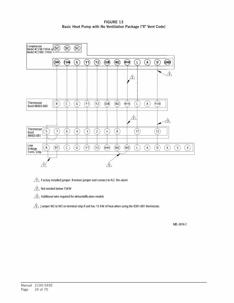
Factory installed jumper. Remove jumper and connect to N.C fire alarm
9
3
2
2
17
1
1
MIS-3016 C
Bard 12
3
5#8403-081
2
Jumper W2 to W3 on terminal strip if unit has 15 KW of heat when using the 8301-081 thermostat.
3
Not needed below 15KW
2
4
3
Additional wire required for dehumidification models
Thermostat867
5
5
FIGURE 13 Basic Heat Pump with No Ventilation Package ("X" Vent Code)

Manual 2100-549ZPage 25 of 70
4W3 A DLB/W1Y2Y1RT GC W2LowVoltageTerm. Strip
R 6 3
W1/E A DLO/BY2Y124V GCOM W2
CompletestatModel #CS9B-THOA orModel #CS9BE-THOA
SC SCSC
GND
W1/E A YO/DLO/BY2Y1R GC W2ThermostatBard #8403-060
7
7
2
MIS-3017 C
4
5
CRV Wiring Harness
1
BROWN/WHITEORANGEBLACK/WHITERED/WHITE
9#8403-081
86 47 3 2
2
175 12ThermostatBard
to N.C fire alarm circuit if emergency shutdown required.
3
Factory installed jumper. Remove jumper and connect
Not needed below 15KW.2
Additional wire required for dehumidification models.
1
1
4
Install a jumper between "G" and "A" only when thermostatwithout "Occupancy Signal" is used.
Connect to "G" terminal when thermostat has "Occupancy Signal".
3
Jumper W2 to W3 on terminal strip if unit has 15 KWof heat when using the 8301-081 thermostat.
5
3
FIGURE 14 Heat Pump with CRV, without CO2 Control ("M" Vent Code)

Manual 2100-549ZPage 26 of 70
5
2
1
6
W1/E A YO/DLO/BY2Y1R GC W2ThermostatBard #8403-060
1
dehumidification models.Additional wire required for
2
65
3
emergency shutdown required.and connect to N.C fire alarm circuit ifFactory installed jumper. Remove jumper
4 has "Occupancy Signal".Connect to "G" terminal when thermostat
Jumper W2 to W3 on terminal strip if unit has 15 KWof heat when using the 8301-081 thermostat.
4
Thermostat
5
CRV Wiring Harness
1
2
2 3
BROWN/WHITEORANGEBLACK/WHITERED/WHITE
4W3 A DLB/W1Y2Y1RT GC W2Term. Strip
R 6
3
3VoltageLow
directly to "A" and do not use seperate CO2 controller.If CS9B-THOC or CS9BE-THOC is used, connect "Brown/White"
without "Occupancy Signal" is used.Install a jumper between "G" and "A" only when thermostat
6Not needed below 15KW.
W1/E A DLO/BY2Y124V GCOM W2Model #CS9BE-THOA
SC SCSC
GND
95
Model #CS9B-THOA orCompletestat
#8403-08186 47 3 2 17 12
6
1Bard
8
8
CO2 ControlBard #8403-096
MIS-3018 D
NOTE: Bard 8403-060 thermostat must be in programmed operation mode and in programmed fan mode for ventilation to function.
FIGURE 15 Heat Pump with CRV and CO2 Control ("M" Vent Code)

Manual 2100-549ZPage 27 of 70
4W3 A DLB/W1Y2Y1RT GC W2LowVoltageTerm. Strip
R 6 3
W1/E A DLO/BY2Y124V GCOM W2
CompletestatModel #CS9B-THOA orModel #CS9BE-THOA
SC SCSC
GND
W1/E A YO/DLO/BY2Y1R GC W2ThermostatBard #8403-060
2
MIS-3019 C
4
BROWN/WHITE
6
Not needed below 15KW.
7
7
1
5
ERV Wiring Harness
2
ORANGEBLACK/WHITERED/WHITE
PURPLEPINK
9
1
#8403-0818
2
47 3 2 17
3
12BardThermostat
1
Additional wire required for dehumidification models.
5
3
to N.C fire alarm circuit if emergency shutdown required.Factory installed jumper. Remove jumper and connect
without "Occupancy Signal" is used.5
Connect to "G" terminal when thermostat has "Occupancy Signal".
Install a jumper between "G" and "A" only when thermostat
4
of heat when using the 8301-081 thermostat.Jumper W2 to W3 on terminal strip if unit has 15 KW
3
NOTE: Bard 8403-060 thermostat must be in programmed operation mode and in programmed fan mode for ventilation to function.
FIGURE 16 Heat Pump with ERV, without CO2 Control ("R" Vent Code)

Manual 2100-549ZPage 28 of 70
W1/E A DLO/BY2Y124V GCOM W2
CompletestatModel #CS9B-THOA orModel #CS9BE-THOA
SC SCSC
GND
W1/E A YO/DLO/BY2Y1R GC W2ThermostatBard #8403-060
8
C
7 46
4
5
ERV Wiring Harness
1
2
23
BROWN/WHITEORANGEBLACK/WHITERED/WHITE
4W3 A DLB/W1Y2Y1RT G
3
W2Term. Strip
R 6
3
3VoltageLow
directly to "A" and do not use seperate CO2 controller.If CS9B-THOC or CS9BE-THOC is used, connect "Brown/White"
PURPLEPINK
2
1
5
6
6
5
6
6
1
"Occupancy Signal".Connect to "G" terminal when thermostat has4
to N.C fire alarm circuit if emergency shutdown required.Factory installed jumper. Remove jumper and connect
3
Not needed below 15KW.2
Additional wire required for dehumidification models.
without "Occupancy Signal" is used.Install a jumper between "G" and "A" only when thermostat5
of heat when using the 8301-081 thermostat.Jumper W2 to W3 on terminal strip if unit has 15 KW
9 12172#8403-081
8
8
ThermostatBard 1
MIS-3020 D
CO2 ControlBard #8403-096
NOTE: Bard 8403-060 thermostat must be in programmed operation mode and in programmed fan mode for ventilation to function.
FIGURE 17 Heat Pump with ERV and CO2 Control (On/Off Cycling) ("R" Vent Code)
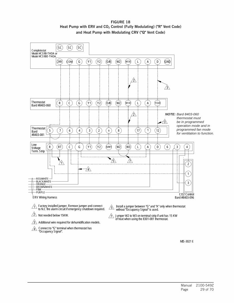
Manual 2100-549ZPage 29 of 70
W1/E A DLO/BY2Y124V GCOM W2
CompletestatModel #CS9B-THOA orModel #CS9BE-THOA
SC SCSC
GND
W1/E A YO/DLO/BY2Y1R GC W2ThermostatBard #8403-060
Thermostat
7
7
1
Additional wire required for dehumidification models.
2 Not needed below 15KW.
3
to N.C fire alarm circuit if emergency shutdown required.Factory installed jumper. Remove jumper and connect
Bard
without "Occupancy Signal" is used.Install a jumper between "G" and "A" only when thermostat5
4
5
ERV Wiring Harness
1
2
3
BROWN/WHITEORANGEBLACK/WHITERED/WHITE
4W3 A DLB/W1Y2Y1RT GC W2Term. Strip
R 6 3
PURPLEPINK
2
1
3
VoltageLow
4"Occupancy Signal".Connect to "G" terminal when thermostat has
of heat when using the 8301-081 thermostat.
95
Jumper W2 to W3 on terminal strip if unit has 15 KW
#8403-08186 47 3 2 17 12
3
1
2
MIS-3021 E
CO2 ControlBard #8403-096
NOTE: Bard 8403-060 thermostat must be in programmed operation mode and in programmed fan mode for ventilation to function.
FIGURE 18 Heat Pump with ERV and CO2 Control (Fully Modulating) ("R" Vent Code)
and Heat Pump with Modulating CRV ("Q" Vent Code)

Manual 2100-549ZPage 30 of 70
Y0 GNDDW2
SC SCSCCompletestatModel #CS9B-THOCA orModel #CS9BE-THOCA
O/BCOM G24V Y1 Y2 W1/E AL
8
MIS-3270 D
BLUE
Additional wire required for dehumidification models.
1
Not needed below 15KW.2to N.C fire alarm circuit if emergency shutdown required.Factory installed jumper. Remove jumper and connect
3
4 Connect orange wire to "G" terminal
41
ORANGEBLACK/WHITERED/WHITE
CRV/ECON Wiring Harness
PURPLEBROWN/WHITE
GRAYYELLOW
PURPLE/WHITEYELLOW/BLACK
7 L AW36
95#8403-081
86 47 3
2
1BardThermostat
of heat when using the 8301-081 thermostat.Jumper W2 to W3 on terminal strip if unit has 15 KW6
3
2 1217
Y2B/W1 Y1DRTerm. Strip
C GRT
6
LowVoltage W2
FIGURE 19 Heat Pump with Combination CRV and DB Economizer (“N” Vent Code)
Only Recommend Bard CS9B-THOC or CS9BE-THOC as Require 3 Heating/Cooling Stages

Manual 2100-549ZPage 31 of 70
START UP
THESE UNITS REQUIRE R-410A REFRIGERANT AND POLYOL ESTER OIL.
GENERAL1. Use separate service equipment to avoid cross
contamination of oil and refrigerants.
2. Use recovery equipment rated for R-410A refrigerant.
3. Use manifold gauges rated for R-410A (800 psi/250 psi low).
4. R-410A is a binary blend of HFC-32 and HFC-125.
5. R-410A is nearly azeotropic—similar to R-22 and R-12. Although nearly azeotropic, charge with liquid refrigerant.
6. R-410A operates at 40-70% higher pressure than R-22, and systems designed for R-22 cannot withstand this higher pressure.
7. R-410A has an ozone depletion potential of zero, but must be reclaimed due to its global warming potential.
8. R-410A compressors use Polyol Ester oil.
9. Polyol Ester oil is hygroscopic; it will rapidly absorb moisture and strongly hold this moisture in the oil.
10. A liquid line dryer must be used—even a deep vacuum will not separate moisture from the oil.
11. Limit atmospheric exposure to 15 minutes.
12. If compressor removal is necessary, always plug compressor immediately after removal. Purge with small amount of nitrogen when inserting plugs.
TOPPING OFF SYSTEM CHARGEIf a leak has occurred in the system, Bard Manufacturing recommends reclaiming, evacuating (see criteria above) and charging to the nameplate charge. However, if done correctly, topping off the system charge can be done without problems.
With R-410A, there are no significant changes in the refrigerant composition during multiple leaks and recharges. R-410A refrigerant is close to being an azeotropic blend (it behaves like a pure compound or single component refrigerant). The remaining refrigerant charge, in the system, may be used after leaks have occurred and then “top-off” the charge by
utilizing the charging charts on the inner control panel cover as a guideline.
REMEMBER: When adding R-410A refrigerant, it must come out of the charging cylinder/tank as a liquid to avoid any fractionation, and to insure optimal system performance. Refer to instructions for the cylinder that is being utilized for proper method of liquid extraction.
SAFETY PRACTICES1. Never mix R-410A with other refrigerants.
2. Use gloves and safety glasses. Polyol Ester oils can be irritating to the skin, and liquid refrigerant will freeze the skin.
3. Never use air and R-410A to leak check; the mixture may become flammable.
4. Do not inhale R-410A; the vapor attacks the nervous system, creating dizziness, loss of coordination and slurred speech. Cardiac irregularities, unconsciousness and ultimate death can result from breathing this concentration.
5. Do not burn R-410A. This decomposition produces hazardous vapors. Evacuate the area if exposed.
6. Use only cylinders rated DOT4BA/4BW 400.
7. Never fill cylinders over 80% of total capacity.
8. Store cylinders in a cool area, out of direct sunlight.
9. Never heat cylinders above 125°F.
10. Never trap liquid R-410A in manifold sets, gauge lines or cylinders. R-410A expands significantly at warmer temperatures. Once a cylinder or line is full of liquid, any further rise in temperature will cause it to burst.
WARNINGFailure to conform to these practices could lead to injury or death.
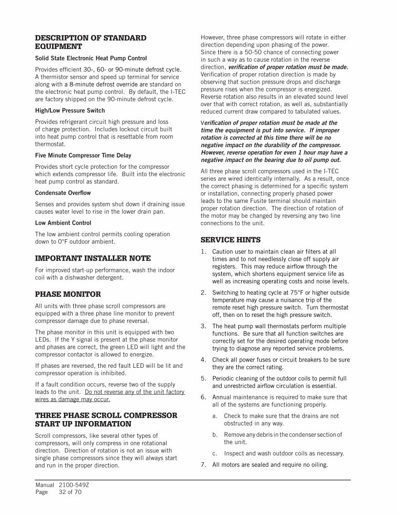
Manual 2100-549ZPage 32 of 70
DESCRIPTION OF STANDARD EQUIPMENTSolid State Electronic Heat Pump Control
Provides efficient 30-, 60- or 90-minute defrost cycle. A thermistor sensor and speed up terminal for service along with a 8-minute defrost override are standard on the electronic heat pump control. By default, the I-TEC are factory shipped on the 90-minute defrost cycle.
High/Low Pressure Switch
Provides refrigerant circuit high pressure and loss of charge protection. Includes lockout circuit built into heat pump control that is resettable from room thermostat.
Five Minute Compressor Time Delay
Provides short cycle protection for the compressor which extends compressor life. Built into the electronic heat pump control as standard.
Condensate Overflow
Senses and provides system shut down if draining issue causes water level to rise in the lower drain pan.
Low Ambient Control
The low ambient control permits cooling operation down to 0°F outdoor ambient.
IMPORTANT INSTALLER NOTEFor improved start-up performance, wash the indoor coil with a dishwasher detergent.
PHASE MONITORAll units with three phase scroll compressors are equipped with a three phase line monitor to prevent compressor damage due to phase reversal.
The phase monitor in this unit is equipped with two LEDs. If the Y signal is present at the phase monitor and phases are correct, the green LED will light and the compressor contactor is allowed to energize.
If phases are reversed, the red fault LED will be lit and compressor operation is inhibited.
If a fault condition occurs, reverse two of the supply leads to the unit. Do not reverse any of the unit factory wires as damage may occur.
THREE PHASE SCROLL COMPRESSOR START UP INFORMATIONScroll compressors, like several other types of compressors, will only compress in one rotational direction. Direction of rotation is not an issue with single phase compressors since they will always start and run in the proper direction.
However, three phase compressors will rotate in either direction depending upon phasing of the power. Since there is a 50-50 chance of connecting power in such a way as to cause rotation in the reverse direction, verification of proper rotation must be made. Verification of proper rotation direction is made by observing that suction pressure drops and discharge pressure rises when the compressor is energized. Reverse rotation also results in an elevated sound level over that with correct rotation, as well as, substantially reduced current draw compared to tabulated values.
Verification of proper rotation must be made at the time the equipment is put into service. If improper rotation is corrected at this time there will be no negative impact on the durability of the compressor. However, reverse operation for even 1 hour may have a negative impact on the bearing due to oil pump out.
All three phase scroll compressors used in the I-TEC series are wired identically internally. As a result, once the correct phasing is determined for a specific system or installation, connecting properly phased power leads to the same Fusite terminal should maintain proper rotation direction. The direction of rotation of the motor may be changed by reversing any two line connections to the unit.
SERVICE HINTS1. Caution user to maintain clean air filters at all
times and to not needlessly close off supply air registers. This may reduce airflow through the system, which shortens equipment service life as well as increasing operating costs and noise levels.
2. Switching to heating cycle at 75°F or higher outside temperature may cause a nuisance trip of the remote reset high pressure switch. Turn thermostat off, then on to reset the high pressure switch.
3. The heat pump wall thermostats perform multiple functions. Be sure that all function switches are correctly set for the desired operating mode before trying to diagnose any reported service problems.
4. Check all power fuses or circuit breakers to be sure they are the correct rating.
5. Periodic cleaning of the outdoor coils to permit full and unrestricted airflow circulation is essential.
6. Annual maintenance is required to make sure that all of the systems are functioning properly.
a. Check to make sure that the drains are not obstructed in any way.
b. Remove any debris in the condenser section of the unit.
c. Inspect and wash outdoor coils as necessary.
7. All motors are sealed and require no oiling.

Manual 2100-549ZPage 33 of 70
SEQUENCE OF OPERATIONCOOLING PART LOAD – Circuit R-Y1 makes at thermostat pulling in compressor contactor, starting the compressor and outdoor motor. The G (indoor motor) circuit is automatically completed on any call for cooling operation or can be energized by manual fan switch on subbase for constant air circulation.
COOLING FULL LOAD – Circuit R-Y1 & Y2 makes at the thermostat energizing the 2nd stage solenoid in the compressor. The default position of the compressor staging solenoid is non-energized. The compressor will run at low capacity until this solenoid is energized.
HEATING STAGE 1 – A 24V solenoid coil on reversing valve controls heating cycle operation. Two thermostat options, one allowing “Auto” changeover from cycle to cycle and the other constantly energizing solenoid coil during heating season and thus eliminating pressure equalization noise except during defrost, are to be used. On “Auto” option a circuit is completed from R-B and R-Y1 on each heating “on” cycle, energizing reversing valve solenoid and pulling in compressor contactor starting compressor and outdoor motor. R-G also make starting indoor blower motor. Heat pump heating cycle now in operation. The second option has no “Auto” changeover position, but instead energizes the reversing valve solenoid constantly whenever the system switch on subbase is placed in “Heat” position, the “B” terminal being constantly energized from R. A thermostat demand for Stage 1 heat completes R-Y1 circuit, pulling in compressor contactor starting compressor and outdoor motor. R-G also make starting indoor blower motor.
HEATING STAGE 2 – Circuit R-Y1 & Y2 makes at the thermostat energizing the 2nd stage solenoid in the compressor.
PRESSURE SERVICE PORTSHigh and low pressure service ports are installed on all units so that the system operating pressures can be observed. Pressure tables can be found later in the manual covering all models. It is imperative to match the correct pressure table to the unit by model number. Upper and lower service doors must be attached to obtain proper reading.
This unit employs high-flow Coremax valves instead of the typical Shrader type valves.
WARNING! Do NOT use a Schrader valve core removal tool with these valves. Use of such a tool could result in eye injuries or refrigerant burns!
To change a Coremax valve without first removing the refrigerant, a special tool is required which can be obtained at www.fastestinc.com/en/SCCA07H. See the replacement parts manual for replacement core part numbers.
LOWERING OUTDOOR FAN SPEED FOR SOUNDSupplied in the literature assembly is a fan control resistor assembly that can be installed to lower the fan speed for reduced sound performance. This resistor assembly is to be installed in series with the outdoor fan control thermistor to change the temperature curve that the fan logic control sees.
It is anticipated that a 2-3% drop in system capacity and efficiency will be seen when this resistor is installed.
To install the resistor assembly:
1. Locate fan control resistor assembly in literature packet hanging on right inside door of unit.
2. Throw main power disconnect to the “OFF” position to eliminate risk of injury or death due to electrical shock.
3. Remove four (4) screws that retain the control panel cover to the unit.
4. Locate fan logic control board.
5. Locate one of the red leads of the fan control thermistor where it attaches to the fan logic control and remove it.
6. Install resistor in-line with the thermistor lead removed in Step #5, and then connect back onto the fan logic control board.
DEFROST CYCLEThe defrost cycle is controlled by temperature and time on the solid state heat pump control. See Figure 20 on page 34.
When the outdoor temperature is in the lower 40°F temperature range or colder, the outdoor coil temperature is 32°F or below. This coil temperature is sensed by the coil temperature sensor mounted near the bottom of the outdoor coil. Once coil temperature reaches 30°F or below, the coil temperature sensor sends a signal to the control logic of the heat pump control and the defrost timer will start accumulating run time.
After 30, 60 or 90 minutes of heat pump operation at 30°F or below, the heat pump control will place the system in the defrost mode. Factory default setting is 90 minutes.
During the defrost mode, the refrigerant cycle switches back to the cooling cycle, the outdoor motor stops, electric heaters are energized and hot gas passing through the outdoor coil melts any accumulated frost. When the temperature rises to approximately 57°F, the coil temperature sensor will send a signal to the heat pump control which will return the system to heating operations automatically.

Manual 2100-549ZPage 34 of 70
If some abnormal or temporary condition such as a high wind causes the heat pump to have a prolonged defrost cycle, the heat pump control will restore the system to heating operation automatically after 8 minutes.
The heat pump defrost control board has an option of 30, 60 or 90-minute setting. All models are shipped from the factory on the 90-minute pin. If special circumstances require a change to another time, remove the wire from the 90-minute terminal and reconnect to the desired terminal.
The manufacturer’s recommendation is for 90-minute defrost cycles. Refer to Figure 20.
There is a cycle speed up jumper on the control. This can be used for testing purposes to reduce the time between defrost cycle operation without waiting for time to elapse.
Use a small screwdriver or other metallic object, or another ¼" QC, to short between the SPEEDUP terminals to accelerate the HPC timer and initiate defrost.
Be careful not to touch any other terminals with the instrument used to short the SPEEDUP terminals. It may take up to 15 seconds with the SPEEDUP terminals shorted for the speedup to be completed and the defrost cycle to start.
As soon as the defrost cycle kicks in remove the shorting instrument from the SPEEDUP terminals. Otherwise the timing will remain accelerated and run through the 1-minute minimum defrost length sequence in a matter of seconds and will automatically terminate the defrost sequence.
There is an initiate defrost jumper (sen jump) on the control that can be used at any outdoor ambient during the heating cycle to simulate a 0° coil temperature.
This can be used to check defrost operation of the unit without waiting for the outdoor ambient to fall into the defrost region.
By placing a jumper across the SEN JMP terminals (a ¼" QC terminal works best) the defrost sensor mounted on the outdoor coil is shunted out and will activate the timing circuit. This permits the defrost cycle to be checked out in warmer weather conditions without the outdoor temperature having to fall into the defrost region.
In order to terminate the defrost test, the SEN JMP jumper must be removed. If left in place too long, the compressor could stop due to the high pressure control opening because of high pressure condition created by operating in the cooling mode with outdoor fan off. Pressure will rise fairly fast as there is likely no actual frost on the outdoor coil in this artificial test condition.
There is also a 5-minute compressor time delay function built into the HPC. This is to protect the compressor from short cycling conditions. The board’s LED will have a fast blink rate when in the compressor time delay. In some instances, it is helpful to the service technician to override or speed up this timing period, and shorting out the SPEEDUP terminals for a few seconds can do this.
120*
SW1
SW2 TIME (SEC)
OFFOFFONON
OFFONOFFON
3060
180
MIS-2668 A
OFF
LOW PRESSURE BYPASS TIMER SWITCH*(FACTORY SETTING 120 SECONDS)
ACCUMULATED DEFROST TIME TIMER(FACTORY SETTING 60 MIN.)
ON
(FACTORY SETTING 90 MIN.)
FIGURE 20 Defrost Cycle

Manual 2100-549ZPage 35 of 70
GENERAL DESCRIPTIONThe I-TEC Commercial Room Ventilator (CRV) is designed to be used with all Bard I-TEC models. The only intent of this device is to provide the required ventilation by delivering fresh air to meet IAQ (Indoor Air Quality) requirements. In the installed application, this system also includes exhaust provisions which are balanced with the intake air to maintain building pressurization requirements of ASHRAE 62.1 Standard.
Ventilation is accomplished with two blower/motor assemblies for maximum ventilation at low sound levels. The intake and exhaust blowers are programmed independently and are balanced to maintain a slight positive pressurization in accordance to ASHRAE 62.1 Standard.
The I-TEC CRV is also provided with filters to reduce the required service needed and to further improve the IAQ. The exhaust air blowers are protected by disposable filters, and the intake air blowers are protected by washable filters. Both are accessible without the need for tools.
CONTROL WIRINGThe I-TEC CRV comes wired from the factory set to 375 CFM of ventilation. Care must be taken when deciding how to control the operation of the ventilator. When designing the control circuit for the ventilator, the following requirements must be met.
1. The indoor blower must be run whenever the I-TEC CRV is run.
2. Select and configure the correct CFM ventilation level that the I-TEC CRV needs to operate and configure the system to this level following later instructions within this section. Over ventilating serves no useful purpose and significantly affects the overall efficiency of the heat pump system. System operating costs would also increase.
3. Run the I-TEC CRV only during periods when the conditioned space is occupied. Running the ventilation during unoccupied periods wastes energy, decreases the expected life of the CRV, and can result in large moisture buildup in the
I-TEC COMMERCIAL ROOM VENTILATOR SYSTEM (VENT CODE "M")
structure. Running the CRV when the structure is unoccupied allows moisture to build up in the structure because there is little or no cooling load. Thus, the air conditioner is not running enough to remove the excess moisture being brought in. Use a control system that in some way can control the system based upon occupancy.
RECOMMENDED CONTROL SEQUENCESSeveral possible scenarios are listed below:
1. Use a programmable electronic thermostat with auxiliary terminal to control the CRV based on daily programmed occupance periods. Bard markets and recommends Bard Part #8403-060 programmable electronic thermostat.
2. Use Bard CompleteStat™ that incorporates temperature, humidity and occupancy control with learning capability into a single device. No programming required.
3. Use a DDC control system based upon a room occupancy schedule to control the CRV.
4. Tie the operation of the CRV into the light switch. The lights in a room are usually on only when occupied.
5. Use a manual timer that the occupants turn to energize the CRV for a specific number of hours.
6. Use a programmable mechanical timer to energize the CRV and indoor blower during occupied periods of the day.
NOTE: The ventilation package comes with a blower interlock function, but is disabled when it is shipped from the factory in case a thermostat with an occupancy output or occupancy sensor is not utilized and “A” terminal to “G” terminal must be tied to drive the ventilation package. If a thermostat or control does drive occupancy output, remove the tape from the orange wire located in the low voltage terminal box and connect it to the “G” terminal to activate this function. (See Figures 13-19.)
SETTING THE VENTILATION CFM LEVELSThe I-TEC CRV has four pre-set levels of ventilation CFM available. These are 300, 375, 450 and 525 CFM of ventilation air. The I-TEC CRV is shipped from the factory set on the 375 CFM ventilation level. To change between these four different levels of provided ventilation CFM, first refer to Figure 21 to look up the
Operating the I-TEC CRV during unoccupied periods can result in a build up of excess moisture in the structure.
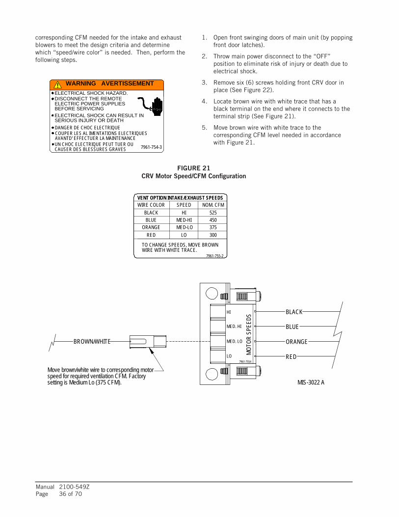
Manual 2100-549ZPage 36 of 70
1. Open front swinging doors of main unit (by popping front door latches).
2. Throw main power disconnect to the “OFF” position to eliminate risk of injury or death due to electrical shock.
3. Remove six (6) screws holding front CRV door in place (See Figure 22).
4. Locate brown wire with white trace that has a black terminal on the end where it connects to the terminal strip (See Figure 21).
5. Move brown wire with white trace to the corresponding CFM level needed in accordance with Figure 21.
corresponding CFM needed for the intake and exhaust blowers to meet the design criteria and determine which “speed/wire color” is needed. Then, perform the following steps.
!
DISCONNECT THE REMOTEELECTRIC POWER SUPPLIESBEFORE SERVICING
7961-754-3
ELECTRICAL SHOCK HAZARD.
ELECTRICAL SHOCK CAN RESULT INSERIOUS INJURY OR DEATHDANGER DE CHOC ELECTRIQUE
UN CHOC ELECTRIQUE PEUT TUER OUCAUSER DES BLESSURES GRAVES
COUPER LES AL IMENTATIONS ELECTRIQUESAVANTD' EFFECTUER LA MAINTENANCE
WARNING AVERTISSEMENT
MED. HI
7961-7554
MOTO
RSP
EEDS
LO
MED. LO
HI
ORANGE
VENT OPTION INTAKE/EXHAUST SPEEDS
BROWN/WHITE
BLACK
BLUE
ORANGE
NOM. CFMBLACKBLUE
WIRE COLOR SPEED
RED
WIRE WITH WHITE TRACE.
300375450525
LOMED-LOMED-HI
HI
RED
Move brown/white wire to corresponding motorspeed for required ventilation CFM. Factorysetting is Medium Lo (375 CFM).
TO CHANGE SPEEDS, MOVE BROWN
7961-755-2
MIS-3022 A
FIGURE 21 CRV Motor Speed/CFM Configuration

Manual 2100-549ZPage 37 of 70
REMOVE (5) SCREWS FROMCRV DOOR TO ACCESS CRVCOMPONENTS
MIS-3023
CRV INTAKE BLOWERNOTE: CRV EXHAUSTBLOWER IS BEHINDINTAKE BLOWER
BLOWER SPEEDCONTROL LOCATION
BLOWERSPEEDCONTROL
BLOWER REMOVEDFOR CLARITY
FIGURE 22 CRV Speed Change Terminal Access

Manual 2100-549ZPage 38 of 70
GENERAL DESCRIPTIONThe I-TEC Combination Commercial Room Ventilator (CRV) and Dry Bulb Economizer is designed to be used with all Bard I-TEC models. This ventilation package and its control provides two roles:
• It will provide the required ventilation by delivering fresh air to meet IAQ (Indoor Air Quality) requirements through CRV portion of the device.
• It will provide up to 525 CFM of free outdoor cooling CFM when the outdoor ambient
I-TEC COMBINATION CRV AND ECONOMIZER VENTILATION SYSTEM (VENT CODE "N")
temperature is below the outdoor thermostat setpoint.
Ventilation is accomplished with two blower/motor assemblies for maximum ventilation at low sound levels. The intake and exhaust blowers are programmed independently and are balanced to maintain a slight positive pressurization in accordance to ASHRAE 62.1 Standard.
The ventilation package is also provided with filters to reduce the required service needed and to further improve the IAQ. The exhaust air blowers are protected by disposable filters and the intake air blowers are protected by washable filters. Both are accessible without the need for tools.
CONTROL WIRINGRefer to Low Voltage Connection (Figure 19).
Reference Figure 23 for Control Sequence of Operation.
7
NC
7
D
R2
6
Y2
NOR3
COM
NO
3
R4
ECON VENT SPEEDYO
A
FACTORY WIRE
A
R1
D
6
G
R
Y2
8
Y1
C
Y1
R4
R2R1R34
COM
R2
7 1R2
58
COM
R2
R1 = DEHUM RELAYR2 = HIGH AMBIENT RELAYR3 = FULL LOAD RELAYR4 = BLOWER INTERLOCK RELAY
FIELD WIRE
CRV VENT SPEED
MIS-3272
UNIT LOWVOLTAGETERMINAL
STRIPTHERMOSTAT
SIGNALS
Operating the I-TEC CRV during unoccupied periods can result in a build up of excess moisture in the structure.
FIGURE 23Economizer Control Circuit

Manual 2100-549ZPage 39 of 70
SETTING THE VENTILATION CFM LEVELSThe I-TEC CRV has four pre-set levels of ventilation CFM available. These are 300, 375, 450 and 525 CFM of ventilation air. This ventilation package is shipped from the factory set on the 375 CFM ventilation level while the economizer portion is set on the 525 CFM ventilation level. To change between these four different levels of provided ventilation CFM, refer to Figure 24 to look up the corresponding CFM needed for the intake and exhaust blowers to meet the design criteria and determine which “speed/wire color” is needed.
Perform the following steps:
1. Open front swinging doors of main unit (by popping front door latches).
2. Throw main power disconnect to the “OFF” position to eliminate risk of injury or death due to electrical shock.
3. Remove six (6) screws holding front CRV door in place (see Figure 22).
4. For CRV blower speed, locate brown wire with white trace that has as black terminal on the end where it connects to the terminal strip (see Figure 24).
5. Move the brown wire with white trace to the corresponding CFM level needed in accordance with Figure 24.
6. For economizer blower speed, locate pink wire that has a black terminal on the end where it connects to the terminal strip (see Figure 24).
7. Move the pink wire to the corresponding CFM level needed in accordance with Figure 24.
FIGURE 24 Motor Speed/CFM Configuration
MED. HI
7961-7554
MOTO
RSP
EEDS
LO
MED. LO
HI
375
VENT OPTION INTAKE/EXHAUST SPEEDS
BROWN/WHITE
BLACK
BLUE
ORANGERED
HIBLACKBLUE
SPEED NOM. CFM
RED
WIRE WITH WHITE TRACE.
300
WIRE COLOR
450525
LOMED-LOMED-HI
ORANGE
Move brown/white wire to corresponding motorspeed for required ventilation CFM. Factorysetting is Medium Lo (375 CFM).
TO CHANGE SPEEDS, MOVE BROWN
7961-755-2
PINK
Move pink wire to corresponding motorspeed for required economizer operation CFM.Factory setting is High (525 CFM).
MIS-3271
Open disconnect to shut all power OFF before doing this! Failure to do so could result in injury or death due to electrical shock.

Manual 2100-549ZPage 40 of 70
I-TEC ECONOMIZER SEQUENCE OF OPERATIONIf Outdoor Temperature is Below Outdoor Thermostat Setpoint
On call from CompleteStatTM for first stage cooling:
• “YO” thermostat signal powers vent blower motors at Economizer Speed/Airflow (black – 525 CFM) through NC contacts of Relay “R1” (“Dehum Relay”).
On call from CompleteStatTM for first and second stage cooling:
• “YO” thermostat signal powers vent blower motors at Economizer Speed/Airflow (black – 525 CFM) through NC contacts of Relay “R1” (“Dehum Relay”).
• “Y1” thermostat signal powers “Y1” terminal on unit low voltage terminal strip through NC contacts of relay “R2” (“High Ambient Relay”).
On call from CompleteStatTM for first, second and third stage cooling:
• “YO” thermostat signal powers vent blower motors at Economizer Speed/Airflow (black – 525 CFM) through NC contacts of Relay “R1” (“Dehum Relay”).
• “Y1” thermostat signal powers “Y1” terminal on unit low voltage terminal strip through NC contacts of relay “R2” (“High Ambient Relay”).
• “Y2” thermostat signal powers “Y2” terminal on unit low voltage terminal strip through NC contacts of relay “R2” (“High Ambient Relay”).
If Outdoor Temperature is Above Outdoor Thermostat Setpoint
On call from CompleteStat for first stage cooling:
• “YO” thermostat signal powers relay coil “R2”. “R2” relay then closes NO contact between “R” and “Y1” at low voltage terminal strip engaging stage 1 mechanical cooling. NC contacts of relay “R2” that connects thermostat “Y1” to “Y1” on low voltage terminal strip is opened to eliminate feedback.
On call from CompleteStatTM for first and second stage cooling:
• “YO” thermostat signal powers relay coil “R2”. “R2” relay then closes NO contact between “R” and “Y1” at low voltage terminal strip engaging stage 1 mechanical cooling. NC contacts of relay “R2” that connects thermostat “Y1” to “Y1” on low voltage terminal strip is opened to eliminate feedback.
• “Y1” thermostat signal powers relay coil “R3” through now closed relay contacts “R2” closing contacts between “R” and “Y2” at low voltage terminal strip.
• “Y2” thermostat signal will do nothing, as NC contacts of relay “R2” are now opened to eliminate any feedback to thermostat.
Dehumidification Mode
On call from CompleteStatTM for dehumidification:
• “D” thermostat signal powers relay coil “R1” (Dehum. Relay). “R1” relay, then opens NC contact between “YO” and outdoor thermostat.
This will then negate any ECONOMIZER SPEED SIGNAL from energizing the ventilation package.
“Y1” & “Y2” thermostat signals will pass through NC contacts of Relay “R2” (“High Ambient Relay”) as relay coil “R2” will be rendered inoperable by “R1” contacts opening. Normal cooling calls can then still apply to override Dehum. call.
HEATING MODE OPERATION
CompleteStat should never energize “YO” terminals in conjunction with “B”, so relay “R2” will never energize, and neither will Economizer Ventilation Speed.
“Y1” and “Y2” signals will pass through NC contacts of relay “R2” contacts, and all heating operations will be normal.
VENTILATION MODEThe call for ventilation will never be disrupted with this control circuit. Anytime “A” signal from CompleteStat is present, the “VENTILATION SPEED” of the vent package will be energized. “A” Signal from thermostat will also energize relay “R4” (“Blower Interlock Relay”) completing a circuit from “R” to “G” through the “NO” contacts to ensure blower operations on the ventilation call.
Manual 2100-549ZPage 41 of 70
I-TEC MODULATING COMMERCIAL ROOM VENTILATOR SYSTEM (VENT CODE "Q")
GENERAL DESCRIPTIONThe I-TEC Commercial Room Ventilator (CRV) is designed to be used with all Bard I-TEC models. The only intent of this device is to provide the required ventilation by delivering fresh air to meet IAQ (Indoor Air Quality) requirements. In the installed application, this system also includes exhaust provisions which are balanced with the intake air to maintain building pressurization requirements of ASHRAE 62.1 Standard.
Ventilation is accomplished with two blower/motor assemblies for maximum ventilation at low sound levels. The intake and exhaust blowers are programmed independently and are balanced to maintain a slight positive pressurization in accordance to ASHRAE 62.1 Standard.
The I-TEC CRV is also provided with filters to reduce the required service needed and to further improve the IAQ. The exhaust air blowers are protected by disposable filters, and the intake air blowers are protected by washable filters. Both are accessible without the need for tools.
CONTROL WIRINGThe I-TEC CRV comes wired from the factory set to 375 CFM of ventilation. Care must be taken when deciding how to control the operation of the ventilator. When designing the control circuit for the ventilator, the following requirements must be met.
1. The indoor blower must be run whenever the I-TEC CRV is run.
2. Select and configure the correct CFM ventilation level that the I-TEC CRV needs to operate and configure the system to this level following later instructions within this section. Over ventilating serves no useful purpose and significantly affects the overall efficiency of the heat pump system. System operating costs would also increase.
3. Run the I-TEC CRV only during periods when the conditioned space is occupied. Running the ventilation during unoccupied periods wastes energy, decreases the expected life of the CRV, and can result in large moisture buildup in the
structure. Running the CRV when the structure is unoccupied allows moisture to build up in the structure because there is little or no cooling load. Thus, the air conditioner is not running enough to remove the excess moisture being brought in. Use a control system that in some way can control the system based upon occupancy.
RECOMMENDED CONTROL SEQUENCESSeveral possible scenarios are listed below:
1. Use a programmable electronic thermostat with auxiliary terminal to control the CRV based on daily programmed occupance periods. Bard markets and recommends Bard Part #8403-060 programmable electronic thermostat.
2. Install a Bard CompleteStat™ with occupancy sensor which learns the room usage and automatically engages ventilation (see Figure 18).
3. Use a DDC control system based upon a room occupancy schedule to control the CRV.
4. Tie the operation of the CRV into the light switch. The lights in a room are usually on only when occupied.
5. Use a manual timer that the occupants turn to energize the CRV for a specific number of hours.
6. Use a programmable mechanical timer to energize the CRV and indoor blower during occupied periods of the day.
NOTE: The ventilation package comes with a blower interlock function, but is disabled when it is shipped from the factory in case a thermostat with an occupancy output or occupancy sensor is not utilized and “A” terminal to “G” terminal must be tied to drive the ventilation package. If a thermostat or control does drive occupancy output, remove the tape from the orange wire located in the low voltage terminal box and connect it to the “G” terminal to activate this function. (See Figures 13-19.)
Operating the I-TEC CRV during unoccupied periods can result in a build up of excess moisture in the structure.

Manual 2100-549ZPage 42 of 70
CHANGING VENTILATION CFM RATES IN MANUAL MODE
!
DISCONNECT THE REMOTEELECTRIC POWER SUPPLIESBEFORE SERVICING
7961-754-3
ELECTRICAL SHOCK HAZARD.
ELECTRICAL SHOCK CAN RESULT INSERIOUS INJURY OR DEATHDANGER DE CHOC ELECTRIQUE
UN CHOC ELECTRIQUE PEUT TUER OUCAUSER DES BLESSURES GRAVES
COUPER LES AL IMENTATIONS ELECTRIQUESAVANTD' EFFECTUER LA MAINTENANCE
WARNING AVERTISSEMENT
To adjust the airflow ventilation rate, first refer to Figure 25A to look up the “FLOW INDEX” needed for the intake and exhaust blowers for the CFM required. Then, perform the following steps:
1. Open front swinging doors of main unit (by popping front door latches).
2. Throw main power disconnect to the “OFF” position to eliminate risk of injury or death due to electrical shock.
3. Remove five (5) screws holding front CRV door in place (see Figure 27).
4. Remove CRV controlpanel cover by removing four (4) screws (see Figure 27).
5. Locate two 0-10Vdc motor control boards in control panel (see Figure 28).
6. On intake motor control board, observing “GREEN STATUS LIGHT”, turn manual adjust potentiometer counterclockwise to increase “FLOW INDEX” or clockwise to reduce “FLOW INDEX” to match desired setting.
NOTE: After long pause, the green status light will blink long-blinks for the “TEN COUNT” of the “FLOW RATE INDEX”, then immediately followed by fast blinks which indicate the second digit. For example, a flow index of 23 would be two long blinks, followed by three fast blinks of the “GREEN STATUS LIGHT”.
7. On exhaust motor control board, observing “GREEN STATUS LIGHT”, turn manual adjust potentiometer counterclockwise to increase “FLOW INDEX” or clockwise to reduce “FLOW INDEX” to match desired setting.
NOTE: Same “GREEN STATUS LIGHT” blink as Step #6.
CHANGING TO FULLY MODULATING MODEIf the CRV is to be operated in fully variable mode (Fig. 25B) (only run at required speed to maintain setpoint CO2 levels), the CRV will need to be configured to the following:
1. Open front swinging doors of main unit (by popping front door latches).
2. Throw main power disconnect to the “OFF” position to eliminate risk of injury or death due to electrical shock.
3. Remove CRV control panel cover by removing four (4) screws (see Figure 27).
4. Locate two 0-10Vdc motor control boards in control panel (see Figure 28).
5. Pull jumper pins from “M” terminals, and move to “P” terminals (see Figure 28).
6. Connect “+” 0-10Vdc output from CO2 control to Terminal #3 (along with pink wire), and connect “-” to Terminal #4 (along with purple wire) of unit low voltage terminal strip.
7. Follow the directions supplied with the CO2 control to configure the control appropriately.
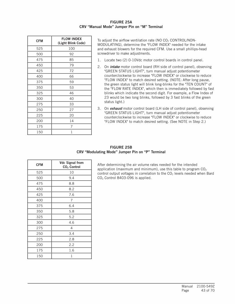
Manual 2100-549ZPage 43 of 70
FIGURE 25A CRV “Manual Mode” Jumper Pin on “M” Terminal
FIGURE 25B CRV “Modulating Mode” Jumper Pin on “P” Terminal
CFM FLOW INDEX(Light Blink Code)
525 100
500 92
475 85
450 79
425 72
400 66
375 59
350 53
325 46
300 40
275 33
250 27
225 20
200 14
175 7
150 1
To adjust the airflow ventilation rate (NO CO2 CONTROL/NON-MODULATING), determine the "FLOW INDEX" needed for the intake and exhaust blowers for the required CFM. Use a small phillips-head screwdriver to make adjustments.
1. Locate two (2) 0-10Vdc motor control boards in control panel.
2. On intake motor control board (RH side of control panel), observing "GREEN STATUS LIGHT", turn manual adjust potentiometer counterclockwise to increase "FLOW INDEX" or clockwise to reduce "FLOW INDEX" to match desired setting. (NOTE: After long pause, the green status light will blink long-blinks for the "TEN COUNT" of the "FLOW RATE INDEX", which then is immediately followed by fast blinks which indicate the second digit. For example, a Flow Index of 23 would be two long blinks, followed by 3 fast blinks of the green status light.)
3. On exhaust motor control board (LH side of control panel), observing "GREEN STATUS LIGHT", turn manual adjust potentiometer counterclockwise to increase "FLOW INDEX" or clockwise to reduce "FLOW INDEX" to match desired setting. (See NOTE in Step 2.)
CFM Vdc Signal from CO2 Control
525 10
500 9.4
475 8.8
450 8.2
425 7.6
400 7
375 6.4
350 5.8
325 5.2
300 4.6
275 4
250 3.4
225 2.8
200 2.2
175 1.6
150 1
After determining the air volume rates needed for the intended application (maximum and minimum), use this table to program CO2 control output voltages in correlation to the CO2 levels needed when Bard CO2 Control 8403-096 is applied.

Manual 2100-549ZPage 44 of 70
EXHAUST
Return Air
Indoor Air VENT
Outdoor Air
BLOWER
BLOWERINTAKE
Supply Air
VENT
SUPPLYBLOWER
MIS-3024
FIGURE 26 Ventilation Airflow Diagram

Manual 2100-549ZPage 45 of 70
PLATES
MIS-3846
CRV CONTROLPANEL LOCATION
CRV DIFFUSER
NOTE: CRVEXHAUSTBLOWER ISBEHIND INTAKEBLOWER
REMOVE (5) SCREWS FROMCRV DOOR TO ACCESS CRVCOMPONENTS
CRV INTAKEBLOWER
FIGURE 27 CRV Control Access
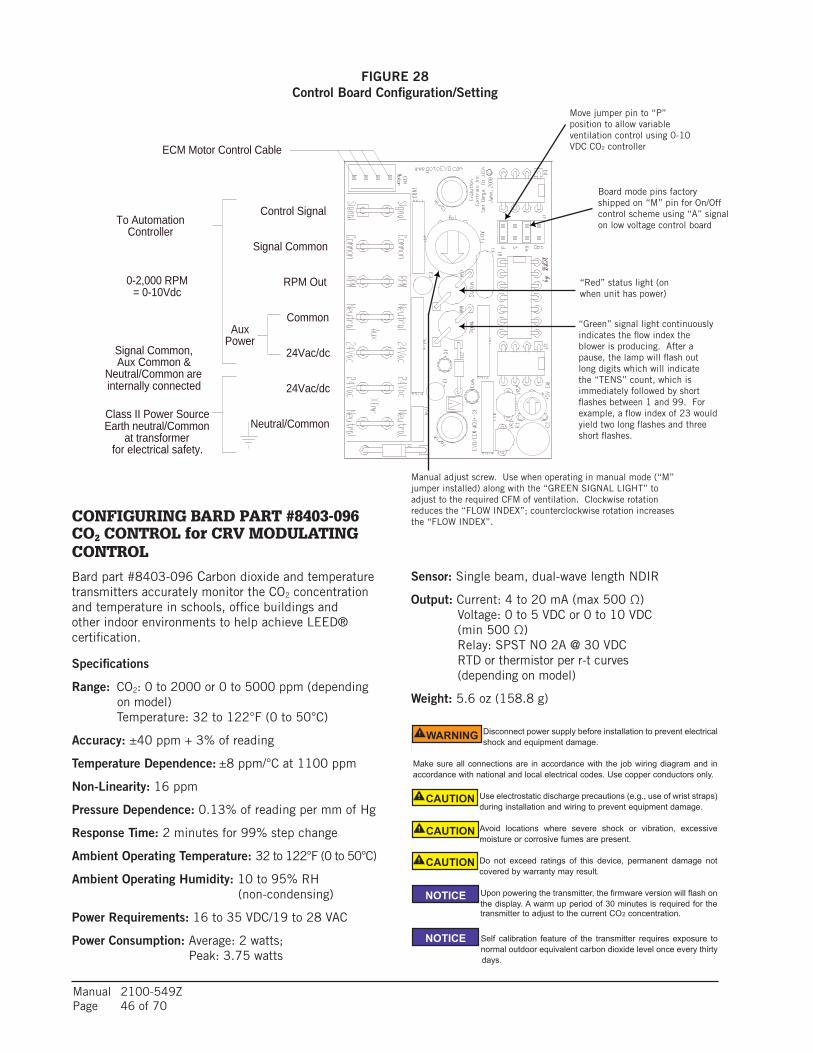
Manual 2100-549ZPage 46 of 70
FIGURE 28 Control Board Configuration/Setting
CONFIGURING BARD PART #8403-096 CO2 CONTROL for CRV MODULATING CONTROL
Bard part #8403-096 Carbon dioxide and temperature transmitters accurately monitor the CO2 concentration and temperature in schools, office buildings and other indoor environments to help achieve LEED® certification.
Specifications
Range: CO2: 0 to 2000 or 0 to 5000 ppm (depending on model)
Temperature: 32 to 122°F (0 to 50°C)
Accuracy: ±40 ppm + 3% of reading
Temperature Dependence: ±8 ppm/°C at 1100 ppm
Non-Linearity: 16 ppm
Pressure Dependence: 0.13% of reading per mm of Hg
Response Time: 2 minutes for 99% step change
Ambient Operating Temperature: 32 to 122°F (0 to 50°C)
Ambient Operating Humidity: 10 to 95% RH (non-condensing)
Power Requirements: 16 to 35 VDC/19 to 28 VAC
Power Consumption: Average: 2 watts; Peak: 3.75 watts
Move jumper pin to “P” position to allow variable ventilation control using 0-10 VDC CO2 controller
Board mode pins factory shipped on “M” pin for On/Off control scheme using “A” signal on low voltage control board
“Red” status light (on when unit has power)
“Green” signal light continuously indicates the flow index the blower is producing. After a pause, the lamp will flash out long digits which will indicate the “TENS” count, which is immediately followed by short flashes between 1 and 99. For example, a flow index of 23 would yield two long flashes and three short flashes.
Manual adjust screw. Use when operating in manual mode (“M” jumper installed) along with the “GREEN SIGNAL LIGHT” to adjust to the required CFM of ventilation. Clockwise rotation reduces the “FLOW INDEX”; counterclockwise rotation increases the “FLOW INDEX”.
Series 1 EVO™/ECM-ACU+
Evolution Controls Inc. p.3 of 4.
©Ev
olut
ion
Con
trols
Inc.
12-M
ay-0
9
0.265"
ø0.1875"
Use #8 FlatheadUse 4m
m Flathead
1.133"
1.429"36.30mm
1.793"45.54mm
64.01mm2.520"
28.78mm
6.73mm
21.3
9mm
0.84
2"44
.45 m
m1.
750"
RPM Out
Neutral/Common
24Vac/dc
24Vac/dc
Common
Signal Common
Control Signal
Class II Power SourceEarth neutral/Common
at transformerfor electrical safety.
Signal Common,Aux Common &
Neutral/Common areinternally connected
AuxPower
ECM Motor Control Cable
To AutomationController
0-2,000 RPM= 0-10Vdc
Mounting
Mount the ACU+ inside a metal control cabinet or enclosure. Fasten the mounting posts to an earthed metal surface.
Mount the ACU+ with clearance for the 24Vac power wires,automation wires and control cable connector. Mount the control so the signal lamps are visible. Make Adjustaccessible if it is used in your application. The control may be surface mounted, or reverse mounted so the LEDs and control shaft are visible through the enclosure wall. Forsurface mount, a silver or white surface under the LEDs makes them more visible from the component side of the ACU+. The control’s motor cable connector is small so it may be carefully pulled through an empty 3/4” conduit.
Keep high voltage wiring away from the ACU+ circuitry or wiring. Follow electrical code requirements for separation of high and low voltage wiring and components.
Wiring
Power the EVO/ECM-ACU+ with a 24Vac NEC Class II USA power limited transformer3. Observe all code requirements and follow all safety practices regarding low voltage power supplies and circuits to insure a safe, reliable installation.
Some applications may require an isolated power supply or alternative earthing scheme. Follow code requirements andcarefully observe all safety practices concerning unearthed low voltage circuits.
Earth one lead of the 24 Vac side of the power transformer4. Connect the ACU+ neutral connection to the earthed lead.
Connect the 24Vac 50/60Hz connection to the hot side of the 24 Vac Class II power source. With the “P” jumper out,you may interrupt this connection as a means to stop the ECM Motor. Most automation controllers will power the ACU+ directly from a 24 Vac on/off output, eliminating the fan relay. Automation controllers that switch neutral may require a fan relay.
The signal input is single-ended, so power neutral and signal common are internally connected.
Connect the 0-10 Vdc control signal to the Signal connection. Connect the control signal common to the Neutral connection.
The input presents a 21K ohm load to the signal source. Include this resistance when calculating a dropping resistor for 4-20 Ma operation. A 511 ohm 1% resistor5
provides a 500 ohm dropping resistance.
Connect to the motor using an EVO/ECM-CBL motor control cable.
3 See NECUSA 725.414 NECUSA 250.20.a.5 www.Mouser.com pn. 271-511-RC
Series CDT Carbon Dioxide and Temperature Transmitters accurately monitorthe CO2 concentration and temperature in schools, office buildings, and otherindoor environments to help achieve LEED® certification. For increased sensorlife, a single- beam dual-wavelength non-dispersive infrared (NDIR) sensor is usedto automatically correct the measurement in both occupied and unoccupiedbuildings against aging effects. The single-beam dual-wavelength sensortechnology provides the highest level of accuracy compared to Automatic BaselineCorrection methods which can unintentionally shift the calibration based on CO2levels and barometric pressure conditions. In order to achieve a higher level ofaccuracy, the Series CDT includes digital barometric pressure adjustment and theability to field-calibrate the sensor.
Universal outputs allow users to select the transmitter output to be 4 to 20 mA, 0to 5 VDC or 0 to 10 VDC to work with virtually any building management controller.An optional relay with user adjustable set points can be used to control exhaustfans, open actuated windows or dampers, or signal a light or horn.
For applications that require visual indication, the Series CDT can be ordered withan integral LCD display or the Model A-449 remote LCD display that can plug intothe mini-connector port on the side of the transmitter. The display can beconfigured to display temperature only, CO2 only or CO2 and temperature together.Push buttons are standard on the transmitters for access to the menu structure,but the transmitter can be ordered without the buttons. To prevent tampering, theaction of the buttons can be locked out using an internal jumper selection. Menuitems that can be accessed include: engineering units, relay output set points,display configuration, transmitter output scaling, ambient barometric pressure andfield calibration of the transmitter.
Single beam dual-wavelength sensor advantages:• Automatically corrects for aging effects in occupied and unoccupied buildings
o Perfect for hospitals and manufacturing plants that are occupied 24 hours per day
• Measures actual unfiltered light intensity directlyo Eliminates error from incorrect assumptions of gas concentration in theoretical
logic assumption methods
Series CDT Carbon Dioxide/Temperature Transmitter
Specifications - Installation and Operating Instructions
Bulletin AQ-CDT
DWYER INSTRUMENTS, INC. phone: 219/879-8000 www.dwyer-inst.comp.O. BOX 373 • MICHIGAN CITY, INDIANA 46361, U.S.A. fax: 219/872-9057 e-mail: [email protected]
SpECIfICATIONSRange:
CO2: 0 to 2000 or 0 to 5000 ppm (depending on model);Temperature: 32 to 122°F (0 to 50°C).
Accuracy: ±40 ppm + 3% of reading.Temperature Dependence: ±8 ppm / °C at 1100 ppm.Non-Linearity: 16 ppm.pressure Dependence: 0.13% of reading per mm of Hg.Response Time: 2 minutes for 99% step change.Ambient Operating Temperature: 32 to 122°F (0 to 50°C).Ambient Operating Humidity: 10 to 95% RH (non-condensing).power Requirements: 16 to 35 VDC / 19 to 28 VAC.power Consumption: Average: 2 watts; Peak: 3.75 watts.Sensor: Single beam, dual-wavelength NDIR.Output:
Current: 4 to 20 mA (max 500 Ω);Voltage: 0 to 5 VDC or 0 to 10 VDC (min 500 Ω);Relay: SPST NO 2A @ 30 VDC;RTD or thermistor per r-t curves (depending on model).
Weight: 5.6 oz (158.8 g).
4-31/64[113.9]
3-13/32[86.52]
35/64[13.89]
1-13/32[35.72]
1-53/64[46.43]
3x 3/8[9.53]
1-13/32[50.01]
1-3/16[30.20]
1-3/16[30.20]
7/8[22.35]
4x 3/16[4.76]
INSTALLATION
Disconnect power supply before installation to prevent electricalshock and equipment damage.
Make sure all connections are in accordance with the job wiring diagram and inaccordance with national and local electrical codes. Use copper conductors only.
Use electrostatic discharge precautions (e.g., use of wrist straps)during installation and wiring to prevent equipment damage.
Avoid locations where severe shock or vibration, excessivemoisture or corrosive fumes are present.
Do not exceed ratings of this device, permanent damage notcovered by warranty may result.
Upon powering the transmitter, the firmware version will flash onthe display. A warm up period of 30 minutes is required for the
transmitter to adjust to the current CO2 concentration.
Self calibration feature of the transmitter requires exposure tonormal outdoor equivalent carbon dioxide level once every thirty days.
WARNING
CAUTION
CAUTION
CAUTION
NOTICE
NOTICE
Sensor: Single beam, dual-wave length NDIR
Output: Current: 4 to 20 mA (max 500 Ω) Voltage: 0 to 5 VDC or 0 to 10 VDC
(min 500 Ω) Relay: SPST NO 2A @ 30 VDC RTD or thermistor per r-t curves
(depending on model)
Weight: 5.6 oz (158.8 g)
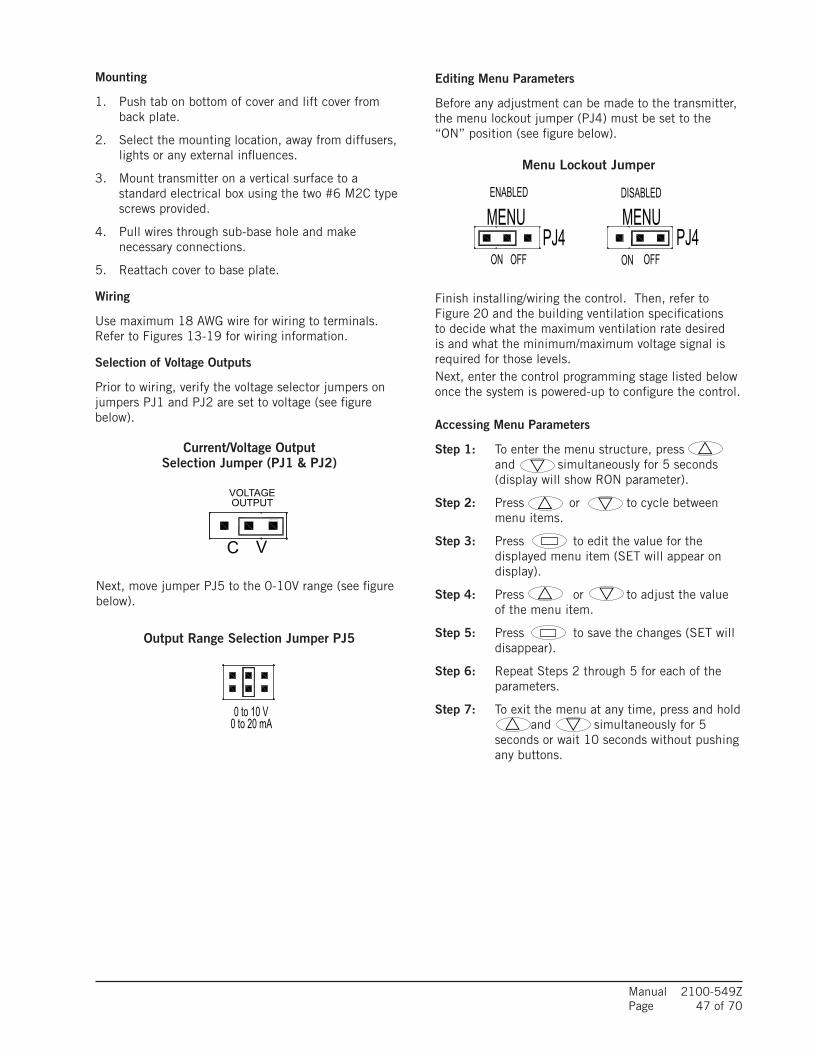
Manual 2100-549ZPage 47 of 70
Mounting
1. Push tab on bottom of cover and lift cover from back plate.
2. Select the mounting location, away from diffusers, lights or any external influences.
3. Mount transmitter on a vertical surface to a standard electrical box using the two #6 M2C type screws provided.
4. Pull wires through sub-base hole and make necessary connections.
5. Reattach cover to base plate.
Wiring
Use maximum 18 AWG wire for wiring to terminals. Refer to Figures 13-19 for wiring information.
Selection of Voltage Outputs
Prior to wiring, verify the voltage selector jumpers on jumpers PJ1 and PJ2 are set to voltage (see figure below).
Next, move jumper PJ5 to the 0-10V range (see figure below).
Editing Menu Parameters
Before any adjustment can be made to the transmitter, the menu lockout jumper (PJ4) must be set to the “ON” position (see figure below).
Finish installing/wiring the control. Then, refer to Figure 20 and the building ventilation specifications to decide what the maximum ventilation rate desired is and what the minimum/maximum voltage signal is required for those levels.Next, enter the control programming stage listed below once the system is powered-up to configure the control.
Accessing Menu Parameters
Step 1: To enter the menu structure, press and simultaneously for 5 seconds (display will show RON parameter).
Step 2: Press or to cycle between menu items.
Step 3: Press to edit the value for the displayed menu item (SET will appear on display).
Step 4: Press or to adjust the value of the menu item.
Step 5: Press to save the changes (SET will disappear).
Step 6: Repeat Steps 2 through 5 for each of the parameters.
Step 7: To exit the menu at any time, press and hold and simultaneously for 5 seconds or wait 10 seconds without pushing any buttons.
Output Range Selection Jumper PJ5
MOUNTING1. Push tab on bottom of cover and lift cover from back plate (See Figure 1).2. Select the mounting location, away from diffusers, lights or any external
influences.3. Mount transmitter on a vertical surface to a standard electrical box using the two
#6 M2C type screws provided.4. Pull wires through sub base hole and make necessary connections.5. Reattach cover to base plate.
WIRING
Use maximum 18 AWG wire for wiring to terminals. Refer to Figure 5 for wiringinformation.
Selection of Current and Voltage OutputsPrior to wiring, verify that the current/voltage selection jumpers (PJ1, PJ2, and PJ5)are set to the desired output type. Refer to Figure 2 to locate the selection jumpers.See Figure 3 for diagram of the current/voltage selection jumper. For voltage outputselection, the output can be 0 to 10 VDC, 0 to 5 VDC, 2 to 10 VDC or 1 to 5 VDC.See Figure 4 for the type of voltage output selection jumper (PJ5).
Current / Voltage OutputsThe transmitter may be wired for current or voltage output for both carbon dioxide andtemperature. The transmitter can be powered with either 16 to 35 VDC or 19 to 28VAC. Wire the transmitter according to Figure 5.
Optional relay can be used as either a dry contact or low voltageswitched circuit up to 2 A at 30 VDC.
Thermistor and RTD OutputsThermistor and RTD passive outputs are located on the back plate and do not requireany power. Passive temperature outputs are not polarity sensitive.
Remote DisplayFor models that are ordered without an integral LCD display, remote display Model A-449 can be used to display the temperature and carbon dioxide. The mini USB plugof the remote display plugs into the receptor on the side of the housing. After a shortwarm up time, the display will begin to show the current temperature and carbondioxide measurements unless configured by the user to show only temperature oronly carbon dioxide.
EDITING MENU pARAMETERS
Before any adjustment can be made to the transmitter, the Menu Lockout Jumper(PJ4) must be set to the ˝On˝ position (See Figure 6).
ACCESSING MENU pARAMETERS
Step 1: To enter the menu structure, press and simultaneously for 5 seconds (display will show RON parameter).
Step 2: Press or to cycle between menu items.
Step 3: Press to edit the value for the displayed menu item (SET will appear on display).
Step 4: Press or to adjust the value of the menu item.
Step 5: Press to save the changes (SET will disappear).
Step 6: Repeat Steps 2 through 5 for each of the parameters.
Step 7: To exit the menu at any time, press and hold and simultaneously for 5 seconds or wait 10 seconds without pushing any buttons.
BOTTOM TAB
HINGETO REMOVE COVERAPPLY PRESSURE TOBOTTOM TAB WHERE INDICATED AND THE TWO PARTS WILL BECOME UNHINGED AT TOP
REVERSE PROCESS TO APPLY COVER
MOUNTINGBACK PLATE
SELF-LATCHINGCOVER
MOUNTINGSCREWS
VOLTAGEOUTPUT
CV VF
2 to 10 V4 to 20 mA
0 to 10 V0 to 20 mA
1 to 5 V2 to 10 mA
F
NOTICE
POWER
SUPPLY
TEMPERATURE
RECEIVER
CO2
RECEIVER
RELAY CONTACT
1 2 3 4 5 6
PW
R
CO
M
OU
T1
OU
T2
RLY
RLY
fIGURE 1: Removal Of Cover from Back plate
fIGURE 4: Output Range Selection Jumper
fIGURE 5: Active Output Wiring Diagram
fIGURE 2: Diagram Of Circuit Board
PJ5PJ4
PJ2
PJ1
ENABLED DISABLED
OFF
MENU MENUPJ4 PJ4
OFFON ON
fIGURE 6: Menu Lockout Jumper
Current/Voltage OutputSelection Jumper (PJ1 & PJ2)
MOUNTING1. Push tab on bottom of cover and lift cover from back plate (See Figure 1).2. Select the mounting location, away from diffusers, lights or any external
influences.3. Mount transmitter on a vertical surface to a standard electrical box using the two
#6 M2C type screws provided.4. Pull wires through sub base hole and make necessary connections.5. Reattach cover to base plate.
WIRING
Use maximum 18 AWG wire for wiring to terminals. Refer to Figure 5 for wiringinformation.
Selection of Current and Voltage OutputsPrior to wiring, verify that the current/voltage selection jumpers (PJ1, PJ2, and PJ5)are set to the desired output type. Refer to Figure 2 to locate the selection jumpers.See Figure 3 for diagram of the current/voltage selection jumper. For voltage outputselection, the output can be 0 to 10 VDC, 0 to 5 VDC, 2 to 10 VDC or 1 to 5 VDC.See Figure 4 for the type of voltage output selection jumper (PJ5).
Current / Voltage OutputsThe transmitter may be wired for current or voltage output for both carbon dioxide andtemperature. The transmitter can be powered with either 16 to 35 VDC or 19 to 28VAC. Wire the transmitter according to Figure 5.
Optional relay can be used as either a dry contact or low voltageswitched circuit up to 2 A at 30 VDC.
Thermistor and RTD OutputsThermistor and RTD passive outputs are located on the back plate and do not requireany power. Passive temperature outputs are not polarity sensitive.
Remote DisplayFor models that are ordered without an integral LCD display, remote display Model A-449 can be used to display the temperature and carbon dioxide. The mini USB plugof the remote display plugs into the receptor on the side of the housing. After a shortwarm up time, the display will begin to show the current temperature and carbondioxide measurements unless configured by the user to show only temperature oronly carbon dioxide.
EDITING MENU pARAMETERS
Before any adjustment can be made to the transmitter, the Menu Lockout Jumper(PJ4) must be set to the ˝On˝ position (See Figure 6).
ACCESSING MENU pARAMETERS
Step 1: To enter the menu structure, press and simultaneously for 5 seconds (display will show RON parameter).
Step 2: Press or to cycle between menu items.
Step 3: Press to edit the value for the displayed menu item (SET will appear on display).
Step 4: Press or to adjust the value of the menu item.
Step 5: Press to save the changes (SET will disappear).
Step 6: Repeat Steps 2 through 5 for each of the parameters.
Step 7: To exit the menu at any time, press and hold and simultaneously for 5 seconds or wait 10 seconds without pushing any buttons.
BOTTOM TAB
HINGETO REMOVE COVERAPPLY PRESSURE TOBOTTOM TAB WHERE INDICATED AND THE TWO PARTS WILL BECOME UNHINGED AT TOP
REVERSE PROCESS TO APPLY COVER
MOUNTINGBACK PLATE
SELF-LATCHINGCOVER
MOUNTINGSCREWS
VOLTAGEOUTPUT
CV VF
2 to 10 V4 to 20 mA
0 to 10 V0 to 20 mA
1 to 5 V2 to 10 mA
F
NOTICE
POWER
SUPPLY
TEMPERATURE
RECEIVER
CO2
RECEIVER
RELAY CONTACT
1 2 3 4 5 6
PW
R
CO
M
OU
T1
OU
T2
RLY
RLY
fIGURE 1: Removal Of Cover from Back plate
fIGURE 4: Output Range Selection Jumper
fIGURE 5: Active Output Wiring Diagram
fIGURE 2: Diagram Of Circuit Board
PJ5PJ4
PJ2
PJ1
ENABLED DISABLED
OFF
MENU MENUPJ4 PJ4
OFFON ON
fIGURE 6: Menu Lockout Jumper
Menu Lockout Jumper
MOUNTING1. Push tab on bottom of cover and lift cover from back plate (See Figure 1).2. Select the mounting location, away from diffusers, lights or any external
influences.3. Mount transmitter on a vertical surface to a standard electrical box using the two
#6 M2C type screws provided.4. Pull wires through sub base hole and make necessary connections.5. Reattach cover to base plate.
WIRING
Use maximum 18 AWG wire for wiring to terminals. Refer to Figure 5 for wiringinformation.
Selection of Current and Voltage OutputsPrior to wiring, verify that the current/voltage selection jumpers (PJ1, PJ2, and PJ5)are set to the desired output type. Refer to Figure 2 to locate the selection jumpers.See Figure 3 for diagram of the current/voltage selection jumper. For voltage outputselection, the output can be 0 to 10 VDC, 0 to 5 VDC, 2 to 10 VDC or 1 to 5 VDC.See Figure 4 for the type of voltage output selection jumper (PJ5).
Current / Voltage OutputsThe transmitter may be wired for current or voltage output for both carbon dioxide andtemperature. The transmitter can be powered with either 16 to 35 VDC or 19 to 28VAC. Wire the transmitter according to Figure 5.
Optional relay can be used as either a dry contact or low voltageswitched circuit up to 2 A at 30 VDC.
Thermistor and RTD OutputsThermistor and RTD passive outputs are located on the back plate and do not requireany power. Passive temperature outputs are not polarity sensitive.
Remote DisplayFor models that are ordered without an integral LCD display, remote display Model A-449 can be used to display the temperature and carbon dioxide. The mini USB plugof the remote display plugs into the receptor on the side of the housing. After a shortwarm up time, the display will begin to show the current temperature and carbondioxide measurements unless configured by the user to show only temperature oronly carbon dioxide.
EDITING MENU pARAMETERS
Before any adjustment can be made to the transmitter, the Menu Lockout Jumper(PJ4) must be set to the ˝On˝ position (See Figure 6).
ACCESSING MENU pARAMETERS
Step 1: To enter the menu structure, press and simultaneously for 5 seconds (display will show RON parameter).
Step 2: Press or to cycle between menu items.
Step 3: Press to edit the value for the displayed menu item (SET will appear on display).
Step 4: Press or to adjust the value of the menu item.
Step 5: Press to save the changes (SET will disappear).
Step 6: Repeat Steps 2 through 5 for each of the parameters.
Step 7: To exit the menu at any time, press and hold and simultaneously for 5 seconds or wait 10 seconds without pushing any buttons.
BOTTOM TAB
HINGETO REMOVE COVERAPPLY PRESSURE TOBOTTOM TAB WHERE INDICATED AND THE TWO PARTS WILL BECOME UNHINGED AT TOP
REVERSE PROCESS TO APPLY COVER
MOUNTINGBACK PLATE
SELF-LATCHINGCOVER
MOUNTINGSCREWS
CURRENTOUTPUT
VOLTAGEOUTPUT
C CV VF
2 to 10 V4 to 20 mA
0 to 10 V0 to 20 mA
0 to 5 V0 to 10 mA
1 to 5 V2 to 10 mA
F
NOTICE
POWER
SUPPLY
TEMPERATURE
RECEIVER
CO2
RECEIVER
RELAY CONTACT
1 2 3 4 5 6
PW
R
CO
M
OU
T1
OU
T2
RLY
RLY
fIGURE 1: Removal Of Cover from Back plate
fIGURE 3: Current/Voltage OutputSelection Jumper (pJ1 And pJ2)
fIGURE 4: Output Range Selection Jumper
fIGURE 5: Active Output Wiring Diagram
fIGURE 2: Diagram Of Circuit Board
PJ5PJ4
PJ2
PJ1
ENABLED DISABLED
OFF
MENU MENUPJ4 PJ4
OFFON ON
fIGURE : Menu Lockout Jumper
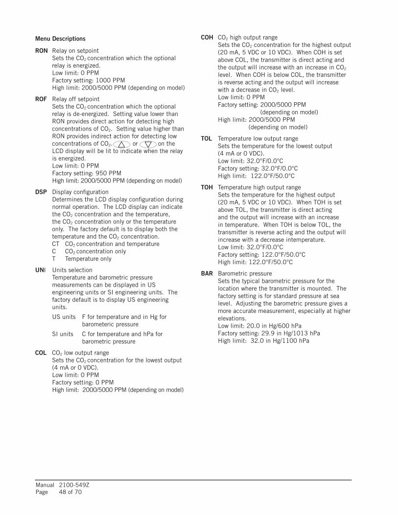
Manual 2100-549ZPage 48 of 70
Menu Descriptions
RON Relay on setpoint Sets the CO2 concentration which the optional
relay is energized. Low limit: 0 PPM Factory setting: 1000 PPM High limit: 2000/5000 PPM (depending on model)
ROF Relay off setpoint Sets the CO2 concentration which the optional
relay is de-energized. Setting value lower than RON provides direct action for detecting high concentrations of CO2. Setting value higher than RON provides indirect action for detecting low concentrations of CO2. or on the LCD display will be lit to indicate when the relay is energized.
Low limit: 0 PPM Factory setting: 950 PPM High limit: 2000/5000 PPM (depending on model)
DSP Display configuration Determines the LCD display configuration during
normal operation. The LCD display can indicate the CO2 concentration and the temperature, the CO2 concentration only or the temperature only. The factory default is to display both the temperature and the CO2 concentration.
CT CO2 concentration and temperature C CO2 concentration only T Temperature only
UNI Units selection Temperature and barometric pressure
measurements can be displayed in US engineering units or SI engineering units. The factory default is to display US engineering units.
US units F for temperature and in Hg for barometeric pressure
SI units C for temperature and hPa for barometric pressure
COL CO2 low output range Sets the CO2 concentration for the lowest output
(4 mA or 0 VDC). Low limit: 0 PPM Factory setting: 0 PPM High limit: 2000/5000 PPM (depending on model)
COH CO2 high output range Sets the CO2 concentration for the highest output
(20 mA, 5 VDC or 10 VDC). When COH is set above COL, the transmitter is direct acting and the output will increase with an increase in CO2 level. When COH is below COL, the transmitter is reverse acting and the output will increase with a decrease in CO2 level.
Low limit: 0 PPM Factory setting: 2000/5000 PPM
(depending on model) High limit: 2000/5000 PPM
(depending on model)
TOL Temperature low output range Sets the temperature for the lowest output
(4 mA or 0 VDC). Low limit: 32.0°F/0.0°C Factory setting: 32.0°F/0.0°C High limit: 122.0°F/50.0°C
TOH Temperature high output range Sets the temperature for the highest output
(20 mA, 5 VDC or 10 VDC). When TOH is set above TOL, the transmitter is direct acting and the output will increase with an increase in temperature. When TOH is below TOL, the transmitter is reverse acting and the output will increase with a decrease intemperature.
Low limit: 32.0°F/0.0°C Factory setting: 122.0°F/50.0°C High limit: 122.0°F/50.0°C
BAR Barometric pressure Sets the typical barometric pressure for the
location where the transmitter is mounted. The factory setting is for standard pressure at sea level. Adjusting the barometric pressure gives a more accurate measurement, especially at higher elevations.
Low limit: 20.0 in Hg/600 hPa Factory setting: 29.9 in Hg/1013 hPa High limit: 32.0 in Hg/1100 hPa

Manual 2100-549ZPage 49 of 70
GENERAL DESCRIPTIONThe I-TEC Energy Recovery Ventilator (ERV) was designed to provide energy efficient, cost effective ventilation to meet IAQ (Indoor Air Quality) requirements while still maintaining good indoor comfort and humidity control for a variety of applications such as schools, classrooms, lounges, conference rooms and others. It provides a constant supply of fresh air for control of airborne pollutants including CO2, smoke, radon, formaldehyde, excess moisture, virus and bacteria.
The ERV incorporates rotary heat exchanger technology to remove both heat and moisture. The package consists of unique rotary energy recovery cassettes that can be easily removed for cleaning or maintenance. It has two 15" diameter heat transfer wheels for efficient heat transfer. The heat transfer wheels use a permanently bonded dry dessicant coating for total heat recovery.
The I-TEC ERV is also provided with filters to reduce the required service needed and to extend the life of the heat recovery wheels. The exhaust air blower is protected by disposable filters, and the intake air blower is protected by washable filters. Both are accessible without the need for tools.
Ventilation is accomplished with two blower/motor assemblies for maximum ventilation at low sound levels. The intake and exhaust blowers can be independently adjusted to maintain desired building pressurization conditions. The rotating wheels provide the heat transfer effectively during both summer and winter conditions. Provides required ventilation to meet the requirements of ASHRAE 62.1 Standard.
NOTE: During operation below 5°F outdoor temperature, freezing of moisture in the heat transfer wheel can occur. Consult the factory if this possibility exists.
The I-TEC ERV can be controlled in different ways. It can be turned ON/OFF with an occupancy control, thermostat or CO2 control. It can also be configured for fully modulating variable speed with a CO2 control to only bring in the minimal amount of ventilation required (helping to minimize sound levels and ventilation load on the structure).
CONTROL WIRINGThe I-TEC ERV comes wired from the factory ready to operate in manual mode (ON/OFF cycling) and set to 375 CFM of ventilation. Care must be taken when deciding how to control the operation of the ventilator. When designing the control circuit for the ventilator, the following requirements must be met.
1. The indoor blower must be run whenever the I-TEC ERV is run.
2. Select and configure the correct CFM ventilation level that the I-TEC ERV needs to operate and configure the system to this level following later instructions within this section. Over ventilating serves no useful purpose and significantly affects the overall efficiency of the heat pump system. System operating costs would also increase.
3. Run the I-TEC ERV only during periods when the conditioned space is occupied. Running the ERV during unoccupied periods wastes energy, decreases the expected life of the ERV and can result in large moisture buildup in the structure. The ERV removes 60-70% of the moisture in the incoming air, not 100% of it. Running the ERV when the structure is unoccupied allows moisture to build up in the structure because there is little or no cooling load. Thus, the air conditioner is not running enough to remove the excess moisture being brought in. Use a control system that in some way can control the system based upon occupancy.
I-TEC ENERGY RECOVERY VENTILATOR SYSTEM (VENT CODE "R")
Operating the I-TEC ERV during unoccupied periods can result in a build up of excess moisture in the structure.

Manual 2100-549ZPage 50 of 70
RECOMMENDED CONTROL SEQUENCESSeveral possible scenarios are listed below:
1. Use a programmable electronic thermostat with auxiliary terminal to control the ERV based on daily programmed occupance periods. Bard markets and recommends Bard Part #8403-060 programmable electronic thermostat.
2. Install a Bard CompleteStatTM with occupancy sensor which learns the room usage and automatically engages ventilation (see Figure 18).
3. Use a DDC control system to control the ERV based upon a room occupancy schedule to control the ERV.
4. Tie the operation of the ERV into the light switch. The lights in a room are usually on only when occupied.
5. Use a manual timer that the occupants turn to energize the ERV for a specific number of hours.
6. Use a programmable mechanical timer to energize the ERV and indoor blower during occupied periods of the day.
NOTE: The ventilation package comes with a blower interlock function, but is disabled when it is shipped from the factory in case a thermostat with an occupancy output or occupancy sensor is not utilized and “A” terminal to “G” terminal must be tied to drive the ventilation package. If a thermostat or control does drive occupancy output, remove the tape from the orange wire located in the low voltage terminal box, and connect it to the “G” terminal to activate this function. (See Figures 13-19.)
CHANGING VENTILATION CFM RATES IN MANUAL MODE
To adjust the airflow ventilation rate, first refer to Figure 29A to look up the “FLOW INDEX” needed for the intake and exhaust blowers for the CFM required. Then, perform the following steps:
1. Open front swinging doors of main unit (by popping front door latches).
2. Throw main power disconnect to the “OFF” position to eliminate risk of injury or death due to electrical shock.
3. Remove five (5) screws holding front ERV door in place (see Figure 31).
4. Remove ERV control panel cover by removing four (4) screws (see Figure 31).
5. Locate two 0-10Vdc motor control boards in control panel (see Figure 32).
6. On intake motor control board, observing “GREEN STATUS LIGHT”, turn manual adjust potentiometer counterclockwise to increase “FLOW INDEX” or clockwise to reduce “FLOW INDEX” to match desired setting.
NOTE: After long pause, the green status light will blink long-blinks for the “TEN COUNT” of the “FLOW RATE INDEX”, then immediately followed by fast blinks which indicate the second digit. For example, a flow index of 23 would be two long blinks, followed by 3 fast blinks of the “GREEN STATUS LIGHT”.
7. On exhaust motor control board, observing “GREEN STATUS LIGHT”, turn manual adjust potentiometer counterclockwise to increase “FLOW INDEX” or clockwise to reduce “FLOW INDEX” to match desired setting.
NOTE: Same “GREEN STATUS LIGHT” blink as Step #6.
CHANGING TO FULLY MODULATING MODEIf the ERV is to be operated in fully variable mode (Fig. 29B) (only run at required speed to maintain setpoint CO2 levels), the ERV will need to be configured to the following:
1. Open front swinging doors of main unit (by popping front door latches).
2. Throw main power disconnect to the “OFF” position to eliminate risk of injury or death due to electrical shock.
3. Remove ERV control panel cover by removing four (4) screws (see Figure 31).
4. Locate two 0-10Vdc motor control boards in control panel (see Figure 32).
5. Pull jumper pins from “M” terminals, and move to “P” terminals (see Figure 32).
6. Connect “+” 0-10Vdc output from CO2 control to Terminal #3 (along with pink wire), and connect “-” to Terminal #4 (along with purple wire) of unit low voltage terminal strip.
7. Follow the directions supplied with the CO2 control to configure the control appropriately.
!
DISCONNECT THE REMOTEELECTRIC POWER SUPPLIESBEFORE SERVICING
7961-754-3
ELECTRICAL SHOCK HAZARD.
ELECTRICAL SHOCK CAN RESULT INSERIOUS INJURY OR DEATHDANGER DE CHOC ELECTRIQUE
UN CHOC ELECTRIQUE PEUT TUER OUCAUSER DES BLESSURES GRAVES
COUPER LES AL IMENTATIONS ELECTRIQUESAVANTD' EFFECTUER LA MAINTENANCE
WARNING AVERTISSEMENT
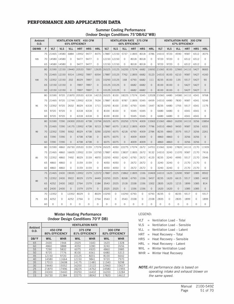
Manual 2100-549ZPage 51 of 70
LEGEND:
VLT = Ventilation Load – TotalVLS = Ventilation Load – SensibleVLL = Ventilation Load – LatentHRT = Heat Recovery – TotalHRS = Heat Recovery – SensibleHRL = Heat Recovery – LatentWVL = Winter Ventilation LoadWHR = Winter Heat Recovery
NOTE: All performance data is based on operating intake and exhaust blower on the same speed.
Winter Heating Performance(Indoor Design Conditions 70°F DB)
PERFORMANCE AND APPLICATION DATA
Summer Cooling Performance(Indoor Design Conditions 75°DB/62°WB)
AmbientO.D.
VENTILATION RATE 450 CFM65% EFFICIENCY
VENTILATION RATE 375 CFM66% EFFICIENCY
VENTILATION RATE 300 CFM67% EFFICIENCY
DB/WB F VLT VLS VLL HRT HRS HRL VLT VLS VLL HRT HRS HRL VLT VLS VLL HRT HRS HRL
105
75 21465 14580 6884 13952 9477 4475 17887 12150 5737 11805 8018 3786 14310 9720 4590 9587 6512 3075
70 14580 14580 0 9477 9477 0 12150 12150 0 8018 8018 0 9720 9720 0 6512 6512 0
65 14580 14580 0 9477 9477 0 12150 12150 0 8018 8018 0 9720 9720 0 6512 6512 0
100
80 31590 12150 19440 20533 7897 12635 26325 10125 16200 17374 6682 10692 21060 8100 12960 14110 5427 8683
75 21465 12150 9314 13952 7897 6054 17887 10125 7762 11805 6682 5123 14310 8100 6210 9587 5427 4160
70 12352 12150 202 8029 7897 131 10293 10125 168 6793 6682 111 8235 8100 135 5517 5427 90
65 12150 12150 0 7897 7897 0 10125 10125 0 6682 6682 0 8100 8100 0 5427 5427 0
60 12150 12150 0 7897 7897 0 10125 10125 0 6682 6682 0 8100 8100 0 5427 5427 0
95
80 31590 9720 21870 20533 6318 14215 26325 8100 18225 17374 5345 12028 21060 6480 14580 14110 4341 9768
75 21465 9720 11744 13952 6318 7634 17887 8100 9787 11805 5345 6459 14310 6480 7830 9587 4341 5246
70 12352 9720 2632 8029 6318 1711 10293 8100 2193 6793 5345 1447 8235 6480 1755 5517 4341 1175
65 9720 9720 0 6318 6318 0 8100 8100 0 5345 5345 0 6480 6480 0 4341 4341 0
60 9720 9720 0 6318 6318 0 8100 8100 0 5345 5345 0 6480 6480 0 4341 4341 0
90
80 31590 7290 24300 20533 4738 15794 26325 6075 20250 17374 4009 13365 21060 4860 16200 14110 3256 10854
75 21465 7290 14175 13952 4738 9213 17887 6075 11812 11805 4009 7796 14310 4860 9450 9587 3256 6331
70 12352 7290 5062 8029 4738 3290 10293 6075 4218 6793 4009 2784 8235 4860 3375 5517 3256 2261
65 7290 7290 0 4738 4738 0 6075 6075 0 4009 4009 0 4860 4860 0 3256 3256 0
60 7290 7290 0 4738 4738 0 6075 6075 0 4009 4009 0 4860 4860 0 3256 3256 0
85
80 31590 4860 26730 20533 3159 17374 26325 4050 22275 17374 2672 14701 21060 3240 17820 14110 2170 11939
75 21465 4860 16605 13952 3159 10793 17887 4050 13837 11805 2672 9132 14310 3240 11070 9587 2170 7416
70 12352 4860 7492 8029 3159 4870 10293 4050 6243 6793 2672 4120 8235 3240 4995 5517 2170 3346
65 4860 4860 0 3159 3159 0 4050 4050 0 2672 2672 0 3240 3240 0 2170 2170 0
60 4860 4860 0 3159 3159 0 4050 4050 0 2672 2672 0 3240 3240 0 2170 2170 0
80
75 21465 2430 19035 13952 1579 12372 17887 2025 15862 11805 1336 10469 14310 1620 12690 9587 1085 8502
70 12352 2430 9922 8029 1579 6449 10293 2025 8268 6793 1336 5457 8235 1620 6615 5517 1085 4432
65 4252 2430 1822 2764 1579 1184 3543 2025 1518 2338 1336 1002 2835 1620 1215 1899 1085 814
60 2430 2430 0 1579 1579 0 2025 2025 0 1336 1336 0 1620 1620 0 1085 1085 0
75
70 12352 0 12352 8029 0 8029 10293 0 10293 6793 0 6793 8235 0 8235 5517 0 5517
65 4252 0 4252 2764 0 2764 3543 0 3543 2338 0 2338 2835 0 2835 1899 0 1899
60 0 0 0 0 0 0 0 0 0 0 0 0 0 0 0 0 0 0
AmbientO.D.
VENTILATION RATE
450 CFM80% EFFICIENCY
375 CFM81% EFFICIENCY
300 CFM82% EFFICIENCY
DB/°F WVL WHR WVL WHR WVL WHR65 2430 1944 2025 1640 1620 132860 4860 3888 4050 3280 3240 265655 7290 5832 6075 4920 4860 398550 9720 7776 8100 6561 6480 531345 12150 9720 10125 8201 8100 664240 14580 11664 12150 9841 9720 797035 17010 13608 14175 11481 11340 929830 19440 15552 16200 13122 12960 1062725 21870 17496 18225 14762 14580 1195520 24300 19440 20250 16402 16200 1328415 26730 21384 22275 18042 17820 14612

Manual 2100-549ZPage 52 of 70
CFM FLOW INDEX(Light Blink Code)
450 100
425 89
400 83
375 76
350 59
325 50
300 40
275 32
250 25
225 12
200 9
175 4
150 1
To adjust the airflow ventilation rate (NO CO2 CONTROL/NON-MODULATING), determine the "FLOW INDEX" needed for the intake and exhaust blowers for the required CFM. Use a small phillips-head screwdriver to make adjustments.
1. Locate two (2) 0-10Vdc motor control boards in control panel.
2. On intake motor control board (RH side of control panel), observing "GREEN STATUS LIGHT", turn manual adjust potentiometer counterclockwise to increase "FLOW INDEX" or clockwise to reduce "FLOW INDEX" to match desired setting. (NOTE: After long pause, the green status light will blink long-blinks for the "TEN COUNT" of the "FLOW RATE INDEX", which then is immediately followed by fast blinks which indicate the second digit. For example, a Flow Index of 23 would be two long blinks, followed by 3 fast blinks of the green status light.)
3. On exhaust motor control board (LH side of control panel), observing "GREEN STATUS LIGHT", turn manual adjust potentiometer counterclockwise to increase "FLOW INDEX" or clockwise to reduce "FLOW INDEX" to match desired setting. (See NOTE in Step 2.)
CFM Vdc Signal from CO2 Control
450 10
425 8.87
400 8.31
375 7.61
350 6.73
325 5.91
300 5.15
275 4.58
250 4.06
225 2.91
200 2.57
175 2.24
150 1.74
125 0.96
100 0.77
After determining the air volume rates needed for the intended application (maximum and minimum), use this table to program CO2 control output voltages in correlation to the CO2 levels needed when Bard CO2 Control 8403-096 is applied.
FIGURE 29A ERV “Manual Mode” Jumper Pin on “M” Terminal
FIGURE 29B ERV “Modulating Mode” Jumper Pin on “P” Terminal

Manual 2100-549ZPage 53 of 70
EXHAUST
Return Air
Indoor Air VENT
Outdoor Air
BLOWER
BLOWERINTAKE
Supply Air
VENT
SUPPLYBLOWER
MIS-3024
FIGURE 30 Ventilation Airflow Diagram

Manual 2100-549ZPage 54 of 70
ERV DOOR TO ACCESS ERVCOMPONENTS
ASSEMBLIES
REMOVE (5) SCREWS FROM
PANEL LOCATION
MIS-3025
ERV CONTROL
ERV CASSETTE
NOTE: ERVEXHAUSTBLOWER ISBEHIND INTAKEBLOWER
ERV INTAKEBLOWER
FIGURE 31 ERV Control Access
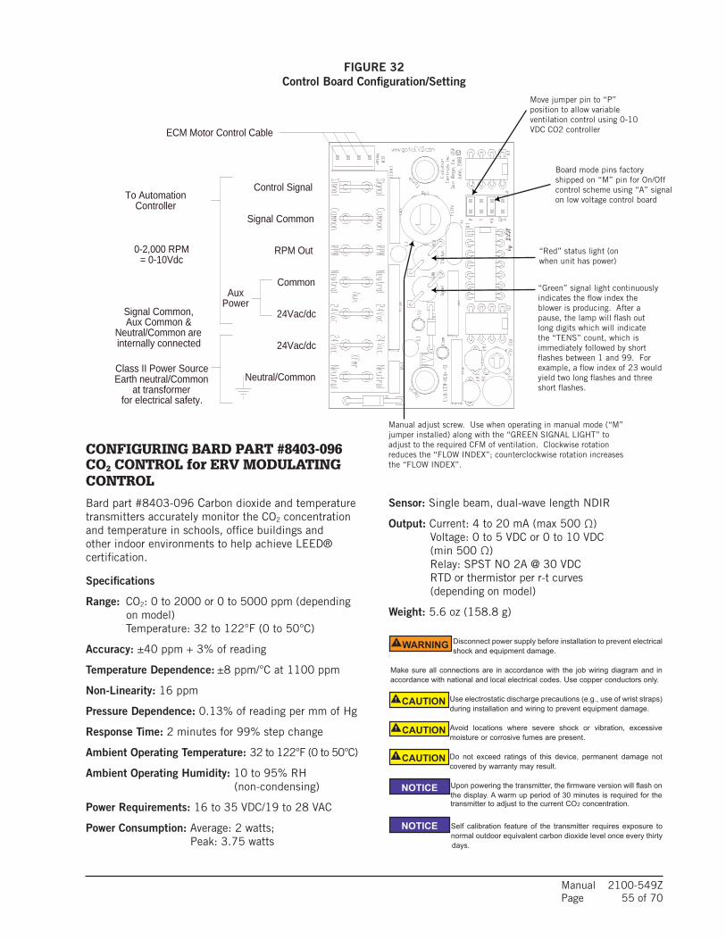
Manual 2100-549ZPage 55 of 70
FIGURE 32 Control Board Configuration/Setting
CONFIGURING BARD PART #8403-096 CO2 CONTROL for ERV MODULATING CONTROL
Bard part #8403-096 Carbon dioxide and temperature transmitters accurately monitor the CO2 concentration and temperature in schools, office buildings and other indoor environments to help achieve LEED® certification.
Specifications
Range: CO2: 0 to 2000 or 0 to 5000 ppm (depending on model)
Temperature: 32 to 122°F (0 to 50°C)
Accuracy: ±40 ppm + 3% of reading
Temperature Dependence: ±8 ppm/°C at 1100 ppm
Non-Linearity: 16 ppm
Pressure Dependence: 0.13% of reading per mm of Hg
Response Time: 2 minutes for 99% step change
Ambient Operating Temperature: 32 to 122°F (0 to 50°C)
Ambient Operating Humidity: 10 to 95% RH (non-condensing)
Power Requirements: 16 to 35 VDC/19 to 28 VAC
Power Consumption: Average: 2 watts; Peak: 3.75 watts
Series CDT Carbon Dioxide and Temperature Transmitters accurately monitorthe CO2 concentration and temperature in schools, office buildings, and otherindoor environments to help achieve LEED® certification. For increased sensorlife, a single- beam dual-wavelength non-dispersive infrared (NDIR) sensor is usedto automatically correct the measurement in both occupied and unoccupiedbuildings against aging effects. The single-beam dual-wavelength sensortechnology provides the highest level of accuracy compared to Automatic BaselineCorrection methods which can unintentionally shift the calibration based on CO2levels and barometric pressure conditions. In order to achieve a higher level ofaccuracy, the Series CDT includes digital barometric pressure adjustment and theability to field-calibrate the sensor.
Universal outputs allow users to select the transmitter output to be 4 to 20 mA, 0to 5 VDC or 0 to 10 VDC to work with virtually any building management controller.An optional relay with user adjustable set points can be used to control exhaustfans, open actuated windows or dampers, or signal a light or horn.
For applications that require visual indication, the Series CDT can be ordered withan integral LCD display or the Model A-449 remote LCD display that can plug intothe mini-connector port on the side of the transmitter. The display can beconfigured to display temperature only, CO2 only or CO2 and temperature together.Push buttons are standard on the transmitters for access to the menu structure,but the transmitter can be ordered without the buttons. To prevent tampering, theaction of the buttons can be locked out using an internal jumper selection. Menuitems that can be accessed include: engineering units, relay output set points,display configuration, transmitter output scaling, ambient barometric pressure andfield calibration of the transmitter.
Single beam dual-wavelength sensor advantages:• Automatically corrects for aging effects in occupied and unoccupied buildings
o Perfect for hospitals and manufacturing plants that are occupied 24 hours per day
• Measures actual unfiltered light intensity directlyo Eliminates error from incorrect assumptions of gas concentration in theoretical
logic assumption methods
Series CDT Carbon Dioxide/Temperature Transmitter
Specifications - Installation and Operating Instructions
Bulletin AQ-CDT
DWYER INSTRUMENTS, INC. phone: 219/879-8000 www.dwyer-inst.comp.O. BOX 373 • MICHIGAN CITY, INDIANA 46361, U.S.A. fax: 219/872-9057 e-mail: [email protected]
SpECIfICATIONSRange:
CO2: 0 to 2000 or 0 to 5000 ppm (depending on model);Temperature: 32 to 122°F (0 to 50°C).
Accuracy: ±40 ppm + 3% of reading.Temperature Dependence: ±8 ppm / °C at 1100 ppm.Non-Linearity: 16 ppm.pressure Dependence: 0.13% of reading per mm of Hg.Response Time: 2 minutes for 99% step change.Ambient Operating Temperature: 32 to 122°F (0 to 50°C).Ambient Operating Humidity: 10 to 95% RH (non-condensing).power Requirements: 16 to 35 VDC / 19 to 28 VAC.power Consumption: Average: 2 watts; Peak: 3.75 watts.Sensor: Single beam, dual-wavelength NDIR.Output:
Current: 4 to 20 mA (max 500 Ω);Voltage: 0 to 5 VDC or 0 to 10 VDC (min 500 Ω);Relay: SPST NO 2A @ 30 VDC;RTD or thermistor per r-t curves (depending on model).
Weight: 5.6 oz (158.8 g).
4-31/64[113.9]
3-13/32[86.52]
35/64[13.89]
1-13/32[35.72]
1-53/64[46.43]
3x 3/8[9.53]
1-13/32[50.01]
1-3/16[30.20]
1-3/16[30.20]
7/8[22.35]
4x 3/16[4.76]
INSTALLATION
Disconnect power supply before installation to prevent electricalshock and equipment damage.
Make sure all connections are in accordance with the job wiring diagram and inaccordance with national and local electrical codes. Use copper conductors only.
Use electrostatic discharge precautions (e.g., use of wrist straps)during installation and wiring to prevent equipment damage.
Avoid locations where severe shock or vibration, excessivemoisture or corrosive fumes are present.
Do not exceed ratings of this device, permanent damage notcovered by warranty may result.
Upon powering the transmitter, the firmware version will flash onthe display. A warm up period of 30 minutes is required for the
transmitter to adjust to the current CO2 concentration.
Self calibration feature of the transmitter requires exposure tonormal outdoor equivalent carbon dioxide level once every thirty days.
WARNING
CAUTION
CAUTION
CAUTION
NOTICE
NOTICE
Sensor: Single beam, dual-wave length NDIR
Output: Current: 4 to 20 mA (max 500 Ω) Voltage: 0 to 5 VDC or 0 to 10 VDC
(min 500 Ω) Relay: SPST NO 2A @ 30 VDC RTD or thermistor per r-t curves
(depending on model)
Weight: 5.6 oz (158.8 g)
Move jumper pin to “P” position to allow variable ventilation control using 0-10 VDC CO2 controller
Board mode pins factory shipped on “M” pin for On/Off control scheme using “A” signal on low voltage control board
“Red” status light (on when unit has power)
“Green” signal light continuously indicates the flow index the blower is producing. After a pause, the lamp will flash out long digits which will indicate the “TENS” count, which is immediately followed by short flashes between 1 and 99. For example, a flow index of 23 would yield two long flashes and three short flashes.
Manual adjust screw. Use when operating in manual mode (“M” jumper installed) along with the “GREEN SIGNAL LIGHT” to adjust to the required CFM of ventilation. Clockwise rotation reduces the “FLOW INDEX”; counterclockwise rotation increases the “FLOW INDEX”.
Series 1 EVO™/ECM-ACU+
Evolution Controls Inc. p.3 of 4.
©Ev
olut
ion
Con
trols
Inc.
12-M
ay-0
9
0.265"
ø0.1875"
Use #8 FlatheadUse 4m
m Flathead
1.133"
1.429"36.30mm
1.793"45.54mm
64.01mm2.520"
28.78mm
6.73mm
21.3
9mm
0.84
2"44
.45 m
m1.
750"
RPM Out
Neutral/Common
24Vac/dc
24Vac/dc
Common
Signal Common
Control Signal
Class II Power SourceEarth neutral/Common
at transformerfor electrical safety.
Signal Common,Aux Common &
Neutral/Common areinternally connected
AuxPower
ECM Motor Control Cable
To AutomationController
0-2,000 RPM= 0-10Vdc
Mounting
Mount the ACU+ inside a metal control cabinet or enclosure. Fasten the mounting posts to an earthed metal surface.
Mount the ACU+ with clearance for the 24Vac power wires,automation wires and control cable connector. Mount the control so the signal lamps are visible. Make Adjustaccessible if it is used in your application. The control may be surface mounted, or reverse mounted so the LEDs and control shaft are visible through the enclosure wall. Forsurface mount, a silver or white surface under the LEDs makes them more visible from the component side of the ACU+. The control’s motor cable connector is small so it may be carefully pulled through an empty 3/4” conduit.
Keep high voltage wiring away from the ACU+ circuitry or wiring. Follow electrical code requirements for separation of high and low voltage wiring and components.
Wiring
Power the EVO/ECM-ACU+ with a 24Vac NEC Class II USA power limited transformer3. Observe all code requirements and follow all safety practices regarding low voltage power supplies and circuits to insure a safe, reliable installation.
Some applications may require an isolated power supply or alternative earthing scheme. Follow code requirements andcarefully observe all safety practices concerning unearthed low voltage circuits.
Earth one lead of the 24 Vac side of the power transformer4. Connect the ACU+ neutral connection to the earthed lead.
Connect the 24Vac 50/60Hz connection to the hot side of the 24 Vac Class II power source. With the “P” jumper out,you may interrupt this connection as a means to stop the ECM Motor. Most automation controllers will power the ACU+ directly from a 24 Vac on/off output, eliminating the fan relay. Automation controllers that switch neutral may require a fan relay.
The signal input is single-ended, so power neutral and signal common are internally connected.
Connect the 0-10 Vdc control signal to the Signal connection. Connect the control signal common to the Neutral connection.
The input presents a 21K ohm load to the signal source. Include this resistance when calculating a dropping resistor for 4-20 Ma operation. A 511 ohm 1% resistor5
provides a 500 ohm dropping resistance.
Connect to the motor using an EVO/ECM-CBL motor control cable.
3 See NECUSA 725.414 NECUSA 250.20.a.5 www.Mouser.com pn. 271-511-RC
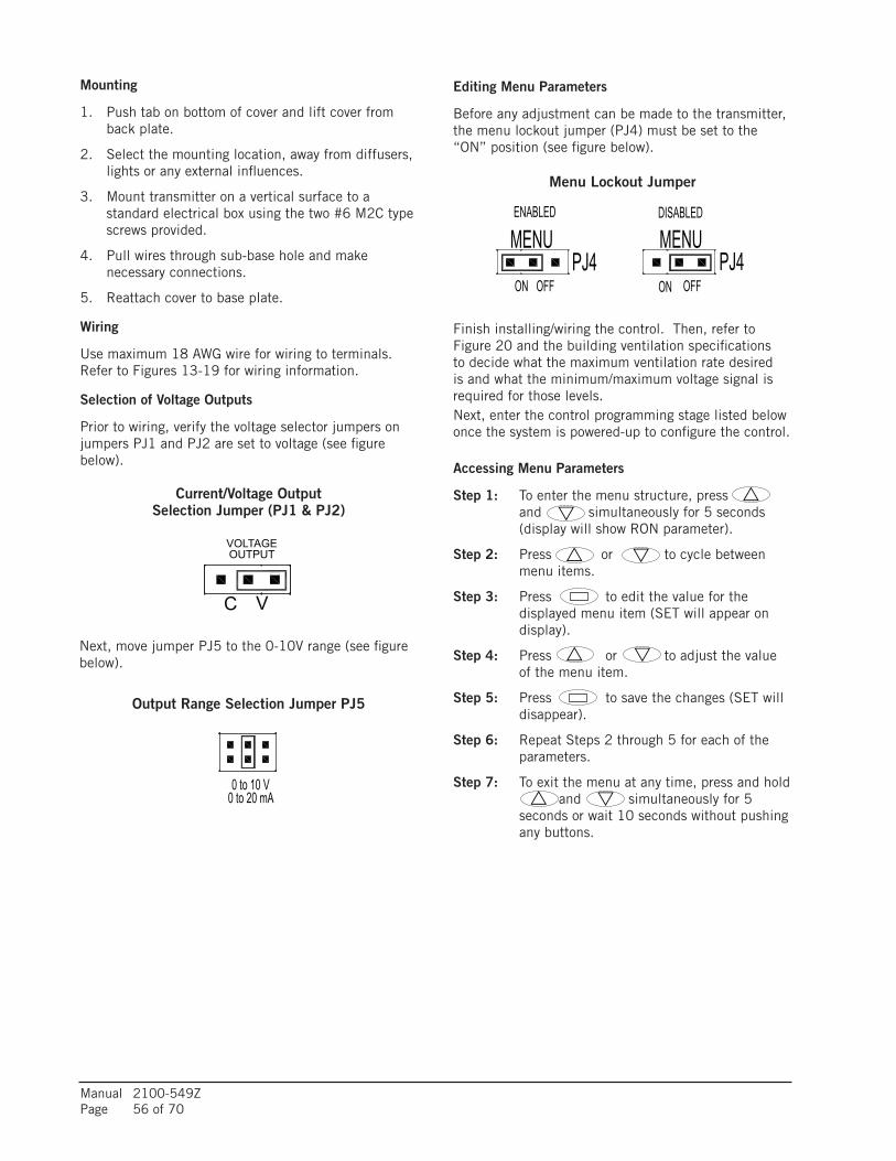
Manual 2100-549ZPage 56 of 70
Mounting
1. Push tab on bottom of cover and lift cover from back plate.
2. Select the mounting location, away from diffusers, lights or any external influences.
3. Mount transmitter on a vertical surface to a standard electrical box using the two #6 M2C type screws provided.
4. Pull wires through sub-base hole and make necessary connections.
5. Reattach cover to base plate.
Wiring
Use maximum 18 AWG wire for wiring to terminals. Refer to Figures 13-19 for wiring information.
Selection of Voltage Outputs
Prior to wiring, verify the voltage selector jumpers on jumpers PJ1 and PJ2 are set to voltage (see figure below).
Next, move jumper PJ5 to the 0-10V range (see figure below).
Editing Menu Parameters
Before any adjustment can be made to the transmitter, the menu lockout jumper (PJ4) must be set to the “ON” position (see figure below).
Finish installing/wiring the control. Then, refer to Figure 20 and the building ventilation specifications to decide what the maximum ventilation rate desired is and what the minimum/maximum voltage signal is required for those levels.Next, enter the control programming stage listed below once the system is powered-up to configure the control.
Accessing Menu Parameters
Step 1: To enter the menu structure, press and simultaneously for 5 seconds (display will show RON parameter).
Step 2: Press or to cycle between menu items.
Step 3: Press to edit the value for the displayed menu item (SET will appear on display).
Step 4: Press or to adjust the value of the menu item.
Step 5: Press to save the changes (SET will disappear).
Step 6: Repeat Steps 2 through 5 for each of the parameters.
Step 7: To exit the menu at any time, press and hold and simultaneously for 5 seconds or wait 10 seconds without pushing any buttons.
Output Range Selection Jumper PJ5
MOUNTING1. Push tab on bottom of cover and lift cover from back plate (See Figure 1).2. Select the mounting location, away from diffusers, lights or any external
influences.3. Mount transmitter on a vertical surface to a standard electrical box using the two
#6 M2C type screws provided.4. Pull wires through sub base hole and make necessary connections.5. Reattach cover to base plate.
WIRING
Use maximum 18 AWG wire for wiring to terminals. Refer to Figure 5 for wiringinformation.
Selection of Current and Voltage OutputsPrior to wiring, verify that the current/voltage selection jumpers (PJ1, PJ2, and PJ5)are set to the desired output type. Refer to Figure 2 to locate the selection jumpers.See Figure 3 for diagram of the current/voltage selection jumper. For voltage outputselection, the output can be 0 to 10 VDC, 0 to 5 VDC, 2 to 10 VDC or 1 to 5 VDC.See Figure 4 for the type of voltage output selection jumper (PJ5).
Current / Voltage OutputsThe transmitter may be wired for current or voltage output for both carbon dioxide andtemperature. The transmitter can be powered with either 16 to 35 VDC or 19 to 28VAC. Wire the transmitter according to Figure 5.
Optional relay can be used as either a dry contact or low voltageswitched circuit up to 2 A at 30 VDC.
Thermistor and RTD OutputsThermistor and RTD passive outputs are located on the back plate and do not requireany power. Passive temperature outputs are not polarity sensitive.
Remote DisplayFor models that are ordered without an integral LCD display, remote display Model A-449 can be used to display the temperature and carbon dioxide. The mini USB plugof the remote display plugs into the receptor on the side of the housing. After a shortwarm up time, the display will begin to show the current temperature and carbondioxide measurements unless configured by the user to show only temperature oronly carbon dioxide.
EDITING MENU pARAMETERS
Before any adjustment can be made to the transmitter, the Menu Lockout Jumper(PJ4) must be set to the ˝On˝ position (See Figure 6).
ACCESSING MENU pARAMETERS
Step 1: To enter the menu structure, press and simultaneously for 5 seconds (display will show RON parameter).
Step 2: Press or to cycle between menu items.
Step 3: Press to edit the value for the displayed menu item (SET will appear on display).
Step 4: Press or to adjust the value of the menu item.
Step 5: Press to save the changes (SET will disappear).
Step 6: Repeat Steps 2 through 5 for each of the parameters.
Step 7: To exit the menu at any time, press and hold and simultaneously for 5 seconds or wait 10 seconds without pushing any buttons.
BOTTOM TAB
HINGETO REMOVE COVERAPPLY PRESSURE TOBOTTOM TAB WHERE INDICATED AND THE TWO PARTS WILL BECOME UNHINGED AT TOP
REVERSE PROCESS TO APPLY COVER
MOUNTINGBACK PLATE
SELF-LATCHINGCOVER
MOUNTINGSCREWS
VOLTAGEOUTPUT
CV VF
2 to 10 V4 to 20 mA
0 to 10 V0 to 20 mA
1 to 5 V2 to 10 mA
F
NOTICE
POWER
SUPPLY
TEMPERATURE
RECEIVER
CO2
RECEIVER
RELAY CONTACT
1 2 3 4 5 6
PW
R
CO
M
OU
T1
OU
T2
RLY
RLY
fIGURE 1: Removal Of Cover from Back plate
fIGURE 4: Output Range Selection Jumper
fIGURE 5: Active Output Wiring Diagram
fIGURE 2: Diagram Of Circuit Board
PJ5PJ4
PJ2
PJ1
ENABLED DISABLED
OFF
MENU MENUPJ4 PJ4
OFFON ON
fIGURE 6: Menu Lockout Jumper
Current/Voltage OutputSelection Jumper (PJ1 & PJ2)
MOUNTING1. Push tab on bottom of cover and lift cover from back plate (See Figure 1).2. Select the mounting location, away from diffusers, lights or any external
influences.3. Mount transmitter on a vertical surface to a standard electrical box using the two
#6 M2C type screws provided.4. Pull wires through sub base hole and make necessary connections.5. Reattach cover to base plate.
WIRING
Use maximum 18 AWG wire for wiring to terminals. Refer to Figure 5 for wiringinformation.
Selection of Current and Voltage OutputsPrior to wiring, verify that the current/voltage selection jumpers (PJ1, PJ2, and PJ5)are set to the desired output type. Refer to Figure 2 to locate the selection jumpers.See Figure 3 for diagram of the current/voltage selection jumper. For voltage outputselection, the output can be 0 to 10 VDC, 0 to 5 VDC, 2 to 10 VDC or 1 to 5 VDC.See Figure 4 for the type of voltage output selection jumper (PJ5).
Current / Voltage OutputsThe transmitter may be wired for current or voltage output for both carbon dioxide andtemperature. The transmitter can be powered with either 16 to 35 VDC or 19 to 28VAC. Wire the transmitter according to Figure 5.
Optional relay can be used as either a dry contact or low voltageswitched circuit up to 2 A at 30 VDC.
Thermistor and RTD OutputsThermistor and RTD passive outputs are located on the back plate and do not requireany power. Passive temperature outputs are not polarity sensitive.
Remote DisplayFor models that are ordered without an integral LCD display, remote display Model A-449 can be used to display the temperature and carbon dioxide. The mini USB plugof the remote display plugs into the receptor on the side of the housing. After a shortwarm up time, the display will begin to show the current temperature and carbondioxide measurements unless configured by the user to show only temperature oronly carbon dioxide.
EDITING MENU pARAMETERS
Before any adjustment can be made to the transmitter, the Menu Lockout Jumper(PJ4) must be set to the ˝On˝ position (See Figure 6).
ACCESSING MENU pARAMETERS
Step 1: To enter the menu structure, press and simultaneously for 5 seconds (display will show RON parameter).
Step 2: Press or to cycle between menu items.
Step 3: Press to edit the value for the displayed menu item (SET will appear on display).
Step 4: Press or to adjust the value of the menu item.
Step 5: Press to save the changes (SET will disappear).
Step 6: Repeat Steps 2 through 5 for each of the parameters.
Step 7: To exit the menu at any time, press and hold and simultaneously for 5 seconds or wait 10 seconds without pushing any buttons.
BOTTOM TAB
HINGETO REMOVE COVERAPPLY PRESSURE TOBOTTOM TAB WHERE INDICATED AND THE TWO PARTS WILL BECOME UNHINGED AT TOP
REVERSE PROCESS TO APPLY COVER
MOUNTINGBACK PLATE
SELF-LATCHINGCOVER
MOUNTINGSCREWS
VOLTAGEOUTPUT
CV VF
2 to 10 V4 to 20 mA
0 to 10 V0 to 20 mA
1 to 5 V2 to 10 mA
F
NOTICE
POWER
SUPPLY
TEMPERATURE
RECEIVER
CO2
RECEIVER
RELAY CONTACT
1 2 3 4 5 6
PW
R
CO
M
OU
T1
OU
T2
RLY
RLY
fIGURE 1: Removal Of Cover from Back plate
fIGURE 4: Output Range Selection Jumper
fIGURE 5: Active Output Wiring Diagram
fIGURE 2: Diagram Of Circuit Board
PJ5PJ4
PJ2
PJ1
ENABLED DISABLED
OFF
MENU MENUPJ4 PJ4
OFFON ON
fIGURE 6: Menu Lockout Jumper
Menu Lockout Jumper
MOUNTING1. Push tab on bottom of cover and lift cover from back plate (See Figure 1).2. Select the mounting location, away from diffusers, lights or any external
influences.3. Mount transmitter on a vertical surface to a standard electrical box using the two
#6 M2C type screws provided.4. Pull wires through sub base hole and make necessary connections.5. Reattach cover to base plate.
WIRING
Use maximum 18 AWG wire for wiring to terminals. Refer to Figure 5 for wiringinformation.
Selection of Current and Voltage OutputsPrior to wiring, verify that the current/voltage selection jumpers (PJ1, PJ2, and PJ5)are set to the desired output type. Refer to Figure 2 to locate the selection jumpers.See Figure 3 for diagram of the current/voltage selection jumper. For voltage outputselection, the output can be 0 to 10 VDC, 0 to 5 VDC, 2 to 10 VDC or 1 to 5 VDC.See Figure 4 for the type of voltage output selection jumper (PJ5).
Current / Voltage OutputsThe transmitter may be wired for current or voltage output for both carbon dioxide andtemperature. The transmitter can be powered with either 16 to 35 VDC or 19 to 28VAC. Wire the transmitter according to Figure 5.
Optional relay can be used as either a dry contact or low voltageswitched circuit up to 2 A at 30 VDC.
Thermistor and RTD OutputsThermistor and RTD passive outputs are located on the back plate and do not requireany power. Passive temperature outputs are not polarity sensitive.
Remote DisplayFor models that are ordered without an integral LCD display, remote display Model A-449 can be used to display the temperature and carbon dioxide. The mini USB plugof the remote display plugs into the receptor on the side of the housing. After a shortwarm up time, the display will begin to show the current temperature and carbondioxide measurements unless configured by the user to show only temperature oronly carbon dioxide.
EDITING MENU pARAMETERS
Before any adjustment can be made to the transmitter, the Menu Lockout Jumper(PJ4) must be set to the ˝On˝ position (See Figure 6).
ACCESSING MENU pARAMETERS
Step 1: To enter the menu structure, press and simultaneously for 5 seconds (display will show RON parameter).
Step 2: Press or to cycle between menu items.
Step 3: Press to edit the value for the displayed menu item (SET will appear on display).
Step 4: Press or to adjust the value of the menu item.
Step 5: Press to save the changes (SET will disappear).
Step 6: Repeat Steps 2 through 5 for each of the parameters.
Step 7: To exit the menu at any time, press and hold and simultaneously for 5 seconds or wait 10 seconds without pushing any buttons.
BOTTOM TAB
HINGETO REMOVE COVERAPPLY PRESSURE TOBOTTOM TAB WHERE INDICATED AND THE TWO PARTS WILL BECOME UNHINGED AT TOP
REVERSE PROCESS TO APPLY COVER
MOUNTINGBACK PLATE
SELF-LATCHINGCOVER
MOUNTINGSCREWS
CURRENTOUTPUT
VOLTAGEOUTPUT
C CV VF
2 to 10 V4 to 20 mA
0 to 10 V0 to 20 mA
0 to 5 V0 to 10 mA
1 to 5 V2 to 10 mA
F
NOTICE
POWER
SUPPLY
TEMPERATURE
RECEIVER
CO2
RECEIVER
RELAY CONTACT
1 2 3 4 5 6
PW
R
CO
M
OU
T1
OU
T2
RLY
RLY
fIGURE 1: Removal Of Cover from Back plate
fIGURE 3: Current/Voltage OutputSelection Jumper (pJ1 And pJ2)
fIGURE 4: Output Range Selection Jumper
fIGURE 5: Active Output Wiring Diagram
fIGURE 2: Diagram Of Circuit Board
PJ5PJ4
PJ2
PJ1
ENABLED DISABLED
OFF
MENU MENUPJ4 PJ4
OFFON ON
fIGURE : Menu Lockout Jumper

Manual 2100-549ZPage 57 of 70
Menu Descriptions
RON Relay on setpoint Sets the CO2 concentration which the optional
relay is energized. Low limit: 0 PPM Factory setting: 1000 PPM High limit: 2000/5000 PPM (depending on model)
ROF Relay off setpoint Sets the CO2 concentration which the optional
relay is de-energized. Setting value lower than RON provides direct action for detecting high concentrations of CO2. Setting value higher than RON provides indirect action for detecting low concentrations of CO2. or on the LCD display will be lit to indicate when the relay is energized.
Low limit: 0 PPM Factory setting: 950 PPM High limit: 2000/5000 PPM (depending on model)
DSP Display configuration Determines the LCD display configuration during
normal operation. The LCD display can indicate the CO2 concentration and the temperature, the CO2 concentration only or the temperature only. The factory default is to display both the temperature and the CO2 concentration.
CT CO2 concentration and temperature C CO2 concentration only T Temperature only
UNI Units selection Temperature and barometric pressure
measurements can be displayed in US engineering units or SI engineering units. The factory default is to display US engineering units.
US units F for temperature and in Hg for barometeric pressure
SI units C for temperature and hPa for barometric pressure
COL CO2 low output range Sets the CO2 concentration for the lowest output
(4 mA or 0 VDC). Low limit: 0 PPM Factory setting: 0 PPM High limit: 2000/5000 PPM (depending on model)
COH CO2 high output range Sets the CO2 concentration for the highest output
(20 mA, 5 VDC or 10 VDC). When COH is set above COL, the transmitter is direct acting and the output will increase with an increase in CO2 level. When COH is below COL, the transmitter is reverse acting and the output will increase with a decrease in CO2 level.
Low limit: 0 PPM Factory setting: 2000/5000 PPM
(depending on model) High limit: 2000/5000 PPM
(depending on model)
TOL Temperature low output range Sets the temperature for the lowest output
(4 mA or 0 VDC). Low limit: 32.0°F/0.0°C Factory setting: 32.0°F/0.0°C High limit: 122.0°F/50.0°C
TOH Temperature high output range Sets the temperature for the highest output
(20 mA, 5 VDC or 10 VDC). When TOH is set above TOL, the transmitter is direct acting and the output will increase with an increase in temperature. When TOH is below TOL, the transmitter is reverse acting and the output will increase with a decrease intemperature.
Low limit: 32.0°F/0.0°C Factory setting: 122.0°F/50.0°C High limit: 122.0°F/50.0°C
BAR Barometric pressure Sets the typical barometric pressure for the
location where the transmitter is mounted. The factory setting is for standard pressure at sea level. Adjusting the barometric pressure gives a more accurate measurement, especially at higher elevations.
Low limit: 20.0 in Hg/600 hPa Factory setting: 29.9 in Hg/1013 hPa High limit: 32.0 in Hg/1100 hPa

Manual 2100-549ZPage 58 of 70
ENERGY RECOVERY VENTILATOR MAINTENANCE
General Information
The ability to clean exposed surfaces within air moving systems is an important design consideration for the maintenance of system performance and air quality. The need for periodic cleaning will be a function of operating schedule, climate and contaminants in the indoor air being exhausted and in the outdoor air being supplied to the building. All components exposed to the airstream, including energy recovery wheels, may require cleaning in most applications.
Rotary counterflow heat exchanges (heat wheels) with laminar airflow are “self-cleaning” with respect to dry particles. Smaller particles pass through; larger particles land on the surface and are blown clear as the flow direction is reversed. For this reason, the primary need for cleaning is to remove films of oil-based aerosols that have condensed on energy transfer surfaces. Buildup of material over time may eventually reduce airflow. Most importantly, in the case of desiccant-coated (enthalpy) wheels, such films can close off micron-sized pores at the surface of the desiccant material, reducing the efficiency with which the desiccant can absorb and desorb moisture.
Frequency
In a reasonably clean indoor environment such as a school, office building or home, experience shows that reductions of airflow or loss of sensible (temperature) effectiveness may not occur for 10 or more years. However, experience also shows that measurable changes in latent energy (water vapor) transfer can occur in shorter periods of time in commercial, institutional and residential applications experiencing moderate occupant smoking or with cooking facilities. In applications experiencing unusually high levels of occupant smoking, such as smoking lounges, nightclubs, bars and restaurants, washing of energy transfer surfaces, as frequently as every 6 months, may be necessary to maintain latent transfer efficiency. Similar washing cycles may also be appropriate for industrial applications involving the ventilation of high levels of smoke or oil-based aerosols such as those found in welding or machining operations, for example. In these applications, latent efficiency losses of as much as 40% or more may develop over a period of 1-3 years.
Cleanability and Performance
In order to maintain energy recovery ventilation systems, energy transfer surfaces must be accessible for washing to remove oils, grease, tars and dirt that can impede performance or generate odors. Washing of the desiccant surfaces is required to remove
contaminate buildups that can reduce adsorption of water molecules. The continued ability of an enthalpy wheel to transfer latent energy depends upon the permanence of the bond between the desiccant and the energy transfer surfaces.
Bard wheels feature silica gel desiccant permanently bonded to the heat exchange surface without adhesives; the desiccant will not be lost in the washing process. Proper cleaning of the Bard energy recovery wheel will restore latent effectiveness to near original performance.
Maintenance Procedures
NOTE: Local conditions can vary and affect the required time between routine maintenance procedures, therefore all sites (or specific units at a site) may not have the same schedule to maintain acceptable performance. The following timetables are recommended and can be altered based on local experience.
Quarterly Maintenance
1. Inspect mist eliminator/prefilter and clean if necessary. This filter is located in the fresh air intake hood on the front of the unit. This is an aluminum mesh filter and can be cleaned with water and any detergent not harmful to aluminum.
2. Inspect wall mount unit filter and clean or replace as necessary. This filter is located either in the unit, in a return air filter grille assembly, or both. If in the unit it can be accessed by removing the lower service door on the front of the unit. If in a return air filter grille, by hinging the grille open to gain access.
3. Inspect energy recovery ventilator for proper wheel rotation and dirt buildup. This can be done in conjunction with Item 2 above. Energize the energy recovery ventilator after inspecting the filter and observe for proper rotation and/or dirt buildup.
4. Recommended energy recovery wheel cleaning procedures follow Steps 5 through 8.
5. Disconnect all power to unit. Remove the lower service door of the wall mount unit to gain access to the energy recovery ventilator.
6. Remove the front access panel on the ventilator. Unplug amp connectors to cassette motors. Slide energy recovery cassette out of ventilator.
7. Use a shop vacuum with brush attachment to clean both sides of the energy recovery wheels.
8. Reverse shop vacuum to use as a blower and blow out any residual dry debris from the wheel.
NOTE: Discoloration and staining of the wheel does not affect its performance. Only excessive
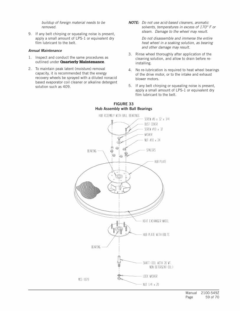
Manual 2100-549ZPage 59 of 70
FIGURE 33Hub Assembly with Ball Bearings
buildup of foreign material needs to be removed.
9. If any belt chirping or squealing noise is present, apply a small amount of LPS-1 or equivalent dry film lubricant to the belt.
Annual Maintenance
1. Inspect and conduct the same procedures as outlined under Quarterly Maintenance.
2. To maintain peak latent (moisture) removal capacity, it is recommended that the energy recovery wheels be sprayed with a diluted nonacid based evaporator coil cleaner or alkaline detergent solution such as 409.
NOTE: Do not use acid-based cleaners, aromatic solvents, temperatures in excess of 170° F or steam. Damage to the wheel may result.
Do not disassemble and immerse the entire heat wheel in a soaking solution, as bearing and other damage may result.
3. Rinse wheel thoroughly after application of the cleaning solution, and allow to drain before re-installing.
4. No re-lubrication is required to heat wheel bearings of the drive motor, or to the intake and exhaust blower motors.
5. If any belt chirping or squealing noise is present, apply a small amount of LPS-1 or equivalent dry film lubricant to the belt.
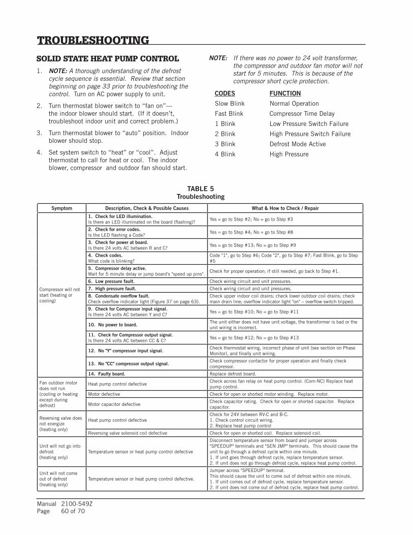
Manual 2100-549ZPage 60 of 70
TROUBLESHOOTING
SOLID STATE HEAT PUMP CONTROL1. NOTE: A thorough understanding of the defrost
cycle sequence is essential. Review that section beginning on page 33 prior to troubleshooting the control. Turn on AC power supply to unit.
2. Turn thermostat blower switch to “fan on”—the indoor blower should start. (If it doesn’t, troubleshoot indoor unit and correct problem.)
3. Turn thermostat blower to “auto” position. Indoor blower should stop.
4. Set system switch to “heat” or “cool”. Adjust thermostat to call for heat or cool. The indoor blower, compressor and outdoor fan should start.
NOTE: If there was no power to 24 volt transformer, the compressor and outdoor fan motor will not start for 5 minutes. This is because of the compressor short cycle protection.
CODES FUNCTION
Slow Blink Normal Operation
Fast Blink Compressor Time Delay
1 Blink Low Pressure Switch Failure
2 Blink High Pressure Switch Failure
3 Blink Defrost Mode Active
4 Blink High Pressure
Symptom Description, Check & Possible Causes What & How to Check / Repair
Compressor will not start (heating or cooling)
1. Check for LED illumination.Is there an LED illuminated on the board (flashing)?
Yes = go to Step #2; No = go to Step #3
2. Check for error codes.Is the LED flashing a Code?
Yes = go to Step #4; No = go to Step #8
3. Check for power at board.Is there 24 volts AC between R and C?
Yes = go to Step #13; No = go to Step #9
4. Check codes.What code is blinking?
Code "1", go to Step #6; Code "2", go to Step #7; Fast Blink, go to Step #5
5. Compressor delay active.Wait for 5 minute delay or jump board's "speed up pins".
Check for proper operation; if still needed, go back to Step #1.
6. Low pressure fault. Check wiring circuit and unit pressures.
7. High pressure fault. Check wiring circuit and unit pressures.
8. Condensate overflow fault.Check overflow indicator light (Figure 37 on page 63).
Check upper indoor coil drains; check lower outdoor coil drains; check main drain line; overflow indicator light "on" – overflow switch tripped.
9. Check for Compressor input signal.Is there 24 volts AC between Y and C?
Yes = go to Step #10; No = go to Step #11
10. No power to board. The unit either does not have unit voltage, the transformer is bad or the unit wiring is incorrect.
11. Check for Compressor output signal.Is there 24 volts AC between CC & C?
Yes = go to Step #12; No = go to Step #13
12. No "Y" compressor input signal. Check thermostat wiring, incorrect phase of unit (see section on Phase Monitor), and finally unit wiring.
13. No "CC" compressor output signal. Check compressor contactor for proper operation and finally check compressor.
14. Faulty board. Replace defrost board.
Fan outdoor motor does not run (cooling or heating except during defrost)
Heat pump control defectiveCheck across fan relay on heat pump control. (Com-NC) Replace heat pump control.
Motor defective Check for open or shorted motor winding. Replace motor.
Motor capacitor defectiveCheck capacitor rating. Check for open or shorted capacitor. Replace capacitor.
Reversing valve does not energize(heating only)
Heat pump control defectiveCheck for 24V between RV-C and B-C.1. Check control circuit wiring.2. Replace heat pump control
Reversing valve solenoid coil defective Check for open or shorted coil. Replace solenoid coil.
Unit will not go into defrost(heating only)
Temperature sensor or heat pump control defective
Disconnect temperature sensor from board and jumper across "SPEEDUP" terminals and "SEN JMP" terminals. This should cause the unit to go through a defrost cycle within one minute.1. If unit goes through defrost cycle, replace temperature sensor.2. If unit does not go through defrost cycle, replace heat pump control.
Unit will not come out of defrost(heating only)
Temperature sensor or heat pump control defective.
Jumper across "SPEEDUP" terminal.This should cause the unit to come out of defrost within one minute. 1. If unit comes out of defrost cycle, replace temperature sensor.2. If unit does not come out of defrost cycle, replace heat pump control.
TABLE 5Troubleshooting
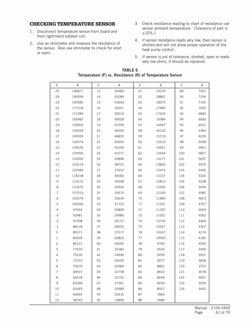
Manual 2100-549ZPage 61 of 70
CHECKING TEMPERATURE SENSOR 1. Disconnect temperature sensor from board and
from right-hand outdoor coil.
2. Use an ohmmeter and measure the resistance of the sensor. Also use ohmmeter to check for short or open.
3. Check resistance reading to chart of resistance use sensor ambient temperature. (Tolerance of part is ±10%.)
4. If sensor resistance reads very low, then sensor is shorted and will not allow proper operation of the heat pump control.
5. If sensor is out of tolerance, shorted, open or reads very low ohms, it should be replaced.
TABLE 6 Temperature (F) vs. Resistance (R) of Temperature Sensor
F R F R F R F R
-25 196871 13 56985 51 19374 89 7507
-24 190099 14 55284 52 18867 90 7334
-23 183585 15 53640 53 18375 91 7165
-22 177318 16 52051 54 17989 92 7000
-21 171289 17 50514 55 17434 93 6840
-20 165487 18 49028 56 16984 94 6683
-19 159904 19 47590 57 16547 95 6531
-18 154529 20 46200 58 16122 96 6383
-17 149355 21 44855 59 15710 97 6239
-16 144374 22 43554 60 15310 98 6098
-15 139576 23 42295 61 14921 99 5961
-14 134956 24 41077 62 14544 100 5827
-13 130506 25 39898 63 14177 101 5697
-12 126219 26 38757 64 13820 102 5570
-11 122089 27 37652 65 13474 103 5446
-10 118108 28 36583 66 13137 104 5326
-9 114272 29 35548 67 12810 105 5208
-8 110575 30 34545 68 12492 106 5094
-7 107010 31 33574 69 12183 107 4982
-6 103574 32 32634 70 11883 108 4873
-5 100260 33 31723 71 11591 109 4767
-4 97064 34 30840 72 11307 110 4663
-3 93981 35 29986 73 11031 111 4562
-2 91008 36 29157 74 10762 112 4464
-1 88139 37 28355 75 10501 113 4367
0 85371 38 27577 76 10247 114 4274
1 82699 39 26823 77 10000 115 4182
2 80121 40 26092 78 9760 116 4093
3 77632 41 25383 79 9526 117 4006
4 75230 42 24696 80 9299 118 3921
5 72910 43 24030 81 9077 119 3838
6 70670 44 23384 82 8862 120 3757
7 68507 45 22758 83 8653 121 3678
8 66418 46 22150 84 8449 122 3601
9 64399 47 21561 85 8250 123 3526
10 62449 48 20989 86 8057 124 3452
11 60565 49 20435 87 7869
12 58745 50 19896 88 7686
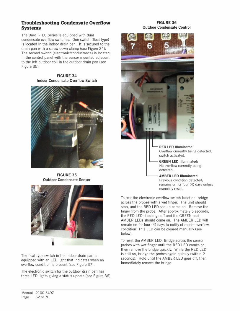
Manual 2100-549ZPage 62 of 70
Troubleshooting Condensate Overflow SystemsThe Bard I-TEC Series is equipped with dual condensate overflow switches. One switch (float type) is located in the indoor drain pan. It is secured to the drain pan with a screw-down clamp (see Figure 34). The second switch (electronic/conductance) is located in the control panel with the sensor mounted adjacent to the left outdoor coil in the outdoor drain pan (see Figure 35).
FIGURE 34 Indoor Condensate Overflow Switch
FIGURE 35 Outdoor Condensate Sensor
To test the electronic overflow switch function, bridge across the probes with a wet finger. The unit should stop, and the RED LED should come on. Remove the finger from the probe. After approximately 5 seconds, the RED LED should go off and the GREEN and AMBER LEDs should come on. The AMBER LED will remain on for four (4) days to notify of recent overflow condition. This LED can be cleared manually (see below).
To reset the AMBER LED: Bridge across the sensor probes with wet finger until the RED LED comes on, then remove the bridge quickly. While the RED LED is still on, bridge the probes again quickly (within 2 seconds). Hold until the AMBER LED goes off, then immediately remove the bridge.
FIGURE 36 Outdoor Condensate Control
RED LED Illuminated: Overflow currently being detected, switch activated.
GREEN LED Illuminated: No overflow currently being detected.
AMBER LED Illuminated: Previous condition detected; remains on for four (4) days unless manually reset.
The float type switch in the indoor drain pan is equipped with an LED light that indicates when an overflow condition is present (see Figure 37).
The electronic switch for the outdoor drain pan has three LED lights giving a status update (see Figure 36).
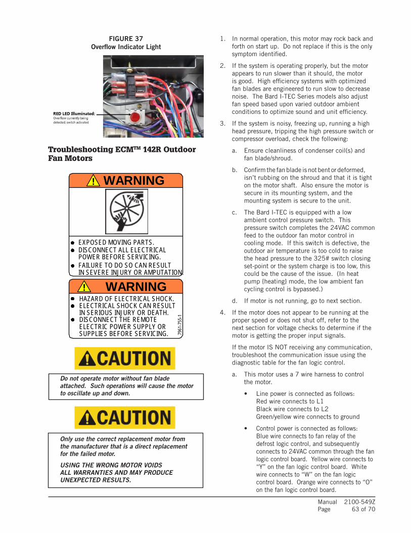
Manual 2100-549ZPage 63 of 70
Troubleshooting ECMTM 142R Outdoor Fan Motors
FIGURE 37 Overflow Indicator Light
1. In normal operation, this motor may rock back and forth on start up. Do not replace if this is the only symptom identified.
2. If the system is operating properly, but the motor appears to run slower than it should, the motor is good. High efficiency systems with optimized fan blades are engineered to run slow to decrease noise. The Bard I-TEC Series models also adjust fan speed based upon varied outdoor ambient conditions to optimize sound and unit efficiency.
3. If the system is noisy, freezing up, running a high head pressure, tripping the high pressure switch or compressor overload, check the following:
a. Ensure cleanliness of condenser coil(s) and fan blade/shroud.
b. Confirm the fan blade is not bent or deformed, isn’t rubbing on the shroud and that it is tight on the motor shaft. Also ensure the motor is secure in its mounting system, and the mounting system is secure to the unit.
c. The Bard I-TEC is equipped with a low ambient control pressure switch. This pressure switch completes the 24VAC common feed to the outdoor fan motor control in cooling mode. If this switch is defective, the outdoor air temperature is too cold to raise the head pressure to the 325# switch closing set-point or the system charge is too low, this could be the cause of the issue. (In heat pump heating mode, the low ambient fan cycling control is bypassed.)
d. If motor is not running, go to next section.
4. If the motor does not appear to be running at the proper speed or does not shut off, refer to the next section for voltage checks to determine if the motor is getting the proper input signals.
If the motor IS NOT receiving any communication, troubleshoot the communication issue using the diagnostic table for the fan logic control.
a. This motor uses a 7 wire harness to control the motor.
• Line power is connected as follows: Red wire connects to L1 Black wire connects to L2 Green/yellow wire connects to ground
• Control power is connected as follows: Blue wire connects to fan relay of the
defrost logic control, and subsequently connects to 24VAC common through the fan logic control board. Yellow wire connects to “Y” on the fan logic control board. White wire connects to “W” on the fan logic control board. Orange wire connects to “O” on the fan logic control board.
Do not operate motor without fan blade attached. Such operations will cause the motor to oscillate up and down.
Only use the correct replacement motor from the manufacturer that is a direct replacement for the failed motor.
USING THE WRONG MOTOR VOIDS ALL WARRANTIES AND MAY PRODUCE UNEXPECTED RESULTS.
2.585 .833 .833
3.706
1.794
4.250
5.500
7961
-755
-3
7961
-755
-3
MOTO
R SP
EEDS
7961-755-4
DISCONNECT ALL ELECTRICAL
IN SEVERE INJURY OR AMPUTATION.
EXPOSED MOVING PARTS.
WARNING
POWER BEFORE SERVICING.
THI
S DO
OR
INTA
KE V
ENT
FILT
ER B
EHIN
D
WIRE WITH WHITE TRACE.
THI
S DO
OR
!
SUPPLIES BEFORE SERVICING.
! WARNING
7961
-755
-1
FAILURE TO DO SO CAN RESULT
7961-755-2
COLORS:
IN SERIOUS INJURY OR DEATH.
LO
DISCONNECT THE REMOTE ELECTRIC POWER SUPPLY OR
MED. HI
WHITE BACKGROUND
MED. LO
VENT OPTION INTAKE/EXHAUST SPEEDS
BRIGHT YELLOW
NAMEPLATE LISTING.BLACK
MATERIAL:
PRINTING:FORM: DIECUT SHEET
END USE: INDOOR/OUTDOOR
7961-755
WIRE COLOR SPEED NOM. CFMBLACKBLUE
ORANGERED
HIMED-HIMED-LO
LO
525450375
DARK ORANGE APPROVED FOR ACCEPTABLE ADHESIVE
300
TO CHANGE SPEEDS, MOVE BROWN
HAZARD OF ELECTRICAL SHOCK.ELECTRICAL SHOCK CAN RESULT
HI
OUTDOOR VINYL, SUPPLIER MUST BE CSA
INTA
KE V
ENT
FILT
ER B
EHIN
D
7961-755

Manual 2100-549ZPage 64 of 70
Check line power to motorCheck between red and black wires for line power
Verify ground by checking green wire to L1 and L2 line power
Check for 24VAC common signal to motor (against transformer "R" signal)
Check "BR" terminal of fan logic control board
Check blue fan lead on fan relay terminal of defrost logic control
** Is not energized in cooling mode until low ambient fan cycling control is closed by 325 PSIG refrigerant pressure. Above 65°F outdoors in cooling mode, the low ambient control is bypassed.
** Circuit is completed automatically when "B" is energized on the fan logic control board
Check 24VAC "hot" outputs (to "blue" on fan logic control) to motor. See the following tables based upon outdoor temperature and model of operation.
NOTE: A combination of the yellow, white and orange wires being energized (with 24V “R” signal) determines five different speeds the fan motor will operate at. The fan logic control board uses an outdoor thermistor sensor to determine the speed the fan should operate. It also utilizes the “B” reversing valve input for heat pump mode to determine which speed should operate.
Troubleshooting Fan Logic Control
Please reference the Thermistor Temperature/Resistance Chart on page 61 (Table 6).
• GREEN STATUS LED – Blinks indicating there is a call for fan operation (simultaneous to call for compressor operation) and is normal.
• RED STATUS LIGHT (LA) – Is illuminated when low ambient control switch is in the closed position. (NOTE: This is not required in heat pump operation as the low ambient switch is bypassed in this mode of operation. Low ambient switch is also negated in cooling mode above 65°F outdoor temperature.)
• YELLOW STATUS LIGHT (B) – Is illuminated when there is a reversing valve call (for heat pump operation). (NOTE: As mentioned above, this mode of operation negates the low ambient fan cycling control.)
If the board is reading a fan temperature thermistor value of 3375Ω or less (equivalent to 125°F or an "open" sensor), the fan will operate at the highest speed setting (energizes "W" and "Y" outputs on the board).
If the board is reading a fan temperature value of 118,110Ω or greater (equivalent to -10°F or a "shorted" sensor), the fan will operate at the highest speed setting (energizes "W" and "Y" outputs on the board).
If the low ambient switch is open, the red light will not be illuminated and the "BR" terminal will show open. The "BR" terminal is the "24 volt common" switching output to the outdoor fan motor.
Replacing the Motor
This motor is replaced in one piece. The control cannot be replaced separately from the motor. Even if the control is remotely located, the replacement part will be a new control with harness and new motor.
The correct replacement motor from the manufacturer that is a direct replacement for the failed motor must be used.
USING THE WRONG MOTOR VOIDS ALL PRODUCT WARRANTIES AND MAY PRODUCE UNEXPECTED RESULTS.
Always mount the replacement motor and control according to the manufacturers specifications using all required hardware to reduce vibration. Make sure all wires are free of the fan blade and not pinched in mountings or cabinet through points.
If the output signals are not matching the specified temperature range, then go to Table #6 on page 61 and verify the thermistor output curve. If the motor is receiving proper communications and proper high voltage power, and is still not running, proceed with motor replacement. (When checking the resistance/temperature curve, don’t forget about the optional 2.2k ohm fan control resistor assembly.)
TABLE 7 Troubleshooting ECM™ 142R Outdoor Fan Motors
O.D. Temp Sensor 24VAC Signals Between
Below 55°F Orange to Blue
Between 56° - 69°F White to Blue
Between 70° - 85°F Yellow to Blue
Between 86° - 112°F Orange and White to Blue
Above 112°F White and Yellow to Blue
TABLE 8 Cooling Mode
O.D. Temp Sensor 24VAC Signals Between
Above 56°F Orange to Blue
Between 55° - 30°F White to Blue
Between 29° - 14°F Yellow to Blue
Below 13°F Orange and White to Blue
TABLE 9 Heat Pump Mode

Manual 2100-549ZPage 65 of 70
Troubleshooting ECMTM Indoor Blower Motors
CAUTION:
Disconnect power from unit before removing or replacing connectors, or servicing motor. To avoid electric shock from the motor’s capacitors, disconnect power and wait at least 5 minutes before opening motor.
Symptom Cause/ProcedureMotor rocks slightly • This is normal start-up for ECMwhen starting
Motor won’t start • Check blower turns by hand• No movement • Check power at motor • Check low voltage (24 Vac R to C) at motor • Check low voltage connections (G, Y, W, R, C) at motor • Check for unseated pins in connectors on motor harness • Test with a temporary jumper between R - G • Check motor for tight shaft • Perform motor/control replacement check • Perform Moisture Check
• Motor rocks, • Check for loose or compliant motor mount but won’t start • Make sure blower wheel is tight on shaft • Perform motor/control replacement check
Motor oscillates up • It is normal for motor to oscillate with no & down while being load on shafttested off of blower
Motor starts, butruns erratically• Varies up and down • Check line voltage for variation or “sag” or intermittent • Check low voltage connections (G, Y, W, R, C) at motor, unseated pins in motor harness connectors • Check “Bk” for erratic CFM command (in variable-speed applications) • Check out system controls, Thermostat • Perform Moisture Check
• “Hunts” or “puffs” at • Does removing panel or filter reduce high CFM (speed) “puffing”? - Reduce restriction - Reduce max airflow
• Stays at low CFM • Check low voltage (Thermostat) wires and despite system call connections for cool or heat CFM • Verify fan is not in delay mode; wait until delay complete • “R” missing/not connected at motor • Perform motor/control replacement check
• Stays at high CFM • “R” missing/not connected at motor • Is fan in delay mode? - wait until delay time complete • Perform motor/control replacement check
• Blower won’t shut off • Current leakage from controls into G, Y or W? Check for Triac switched thermostat or solid- state relay
Excessive noise • Determine if it’s air noise, cabinet, duct or motor noise; interview customer, if necessary• Air noise • High static creating high blower speed? - Is airflow set properly? - Does removing filter cause blower to slow down? Check filter - Use low-pressure drop filter - Check/correct duct restrictions
Symptom Cause/Procedure• Noisy blower or cabinet • Check for loose blower housing, panels, etc. • High static creating high blower speed? - Check for air whistling through seams in ducts, cabinets or panels - Check for cabinet/duct deformation
• “Hunts” or “puffs” at • Does removing panel or filter reduce high CFM (speed) “puffing”? - Reduce restriction - Reduce max. airflow
Evidence of Moisture• Motor failure or • Replace motor and Perform Moisture Check malfunction has occurred and moisture is present• Evidence of moisture
• Perform Moisture Check present inside air mover
Do Don’t• Check out motor, controls, • Automatically assume the motor is bad. wiring and connections thoroughly before replacing motor• Orient connectors down so • Locate connectors above 7 and 4 o’clock water can’t get in positions - Install “drip loops”• Use authorized motor and • Replace one motor or control model # with model #’s for replacement another (unless an authorized replacement)• Keep static pressure to a • Use high pressure drop filters; some have ½" minimum: H20 drop! - Recommend high • Use restricted returns efficiency, low static filters - Recommend keeping filters clean. - Design ductwork for min. static, max. comfort - Look for and recommend ductwork improvement, where necessary
• Size the equipment wisely • Oversize system, then compensate with low airflow• Check orientation before • Plug in power connector backwards inserting motor connectors • Force plugs
Moisture Check• Connectors are oriented “down” (or as recommended by equipment manufacturer)• Arrange harness with “drip loop” under motor• Is condensate drain plugged?• Check for low airflow (too much latent capacity)• Check for undercharged condition• Check and plug leaks in return ducts, cabinet
Comfort Check• Check proper airflow settings• Low static pressure for lowest noise• Set low continuous-fan CFM• Use humidistat and 2-speed cooling units• Use zoning controls designed for ECM that regulate CFM• Thermostat in bad location?

Manual 2100-549ZPage 66 of 70
Motor
Motor OK whenR > 100k ohm
Connector OrientationBetween 4 and 8 o'clock
Drip Loop
Back ofControl
Winding Test
ECM 2.3/2.5
Power Connector(5-pin)
Control Connector(16-pin)
Motor Connector(3-pin)
Motor Connector(3-pin)
Control Disassembly
Drip Loop
Push untilLatch SeatsOver Ramp
From Motor
CircuitBoard
Replacing ECM Control ModuleTo replace the control module for the GE variable-speed indoor blower motor you need to take the following steps:1. The correct replacement module must be used. The controls are
factory programmed for specific operating modes. Even though they look alike, different modules may have completely different functionality.
USING THE WRONG CONTROL MODULE VOIDS ALL PRODUCT WARRANTIES AND MAY PRODUCE UNEXPECTED RESULTS.2. Begin by removing AC power from the unit being serviced. DO
NOT WORK ON THE MOTOR WITH AC POWER APPLIED. To avoid electric shock from the motor’s capacitors, disconnect power and wait at least 5 minutes before opening motor.
3. It is not necessary to remove the motor from the blower assembly, nor the blower assembly from the unit. Unplug the two cable connectors to the motor control assembly. There are latches on each connector. DO NOT PULL ON THE WIRES. The plugs remove easily when properly released.
4. Locate the screws that retain to the motor control bracket to the sheet metal of the unit and remove them. Remove two (2) nuts that retain the control to the bracket and then remove two (2) nuts that retain sheet metal motor control end plate. Refer to Figure 38.
5. Disconnect the three (3) wires interior of the motor control by using a thumb and forefinger to squeeze the latch tab and the opposite side of the connector plug, gently pulling the connector. DO NOT PULL ON THE WIRES, GRIP THE PLUG ONLY. Refer to Figure 38.
6. The control module is now completely detached from the motor. Verify with a standard ohmmeter that the resistance from each motor lead (in the motor plug just removed) to the motor shell is >100K ohms. Refer to Figure 39. (Measure to unpainted motor end plate.) If any motor lead fails this test, do not proceed to install the control module. THE MOTOR IS DEFECTIVE AND MUST BE REPLACED. Installing the new control module will cause it to fail also.
7. Verify that the replacement control is correct for the application. Refer to the manufacturer’s authorized replacement list. USING THE WRONG CONTROL WILL RESULT IN IMPROPER OR NO BLOWER OPERATION. Orient the control module so that the 3-wire motor plug can be inserted into the socket in the control. Carefully insert the plug and press it into the socket until it latches. A SLIGHT CLICK WILL BE HEARD WHEN PROPERLY INSERTED.
8. Reverse Steps 3-5 to reconnect the motor control to the motor wires, securing the motor control cover plate, mounting the control to the bracket and mounting the motor control bracket back into the unit. MAKE SURE THE ORIENTATION SELECTED FOR REPLACING THE CONTROL ENSURES THE CONTROL’S CABLE CONNECTORS WILL BE LOCATED DOWNWARD IN THE APPLICATION SO THAT WATER CANNOT RUN DOWN THE CABLES AND INTO THE CONTROL. DO NOT OVERTIGHTEN THE BOLTS.
9. Plug the 16-pin control plug into the motor. The plug is keyed. Make sure the connector is properly seated and latched.
10. Plug the 5-pin power connector into the motor. Even though the plug is keyed, OBSERVE THE PROPER ORIENTATION. DO NOT FORCE THE CONNECTOR. It plugs in very easily when properly oriented. REVERSING THIS PLUG WILL CAUSE IMMEDIATE FAILURE OF THE CONTROL MODULE.
11. Final installation check. Make sure the motor is installed as follows:
a. Motor connectors should be oriented between the 4 o’clock and 8 o’clock positions when the control is positioned in its final location and orientation.
b. Add a drip loop to the cables so that water cannot enter the motor by draining down the cables. Refer to Figure 40.
The installation is now complete. Reapply AC power to the HVAC equipment and verify that the new motor control module is working properly. Follow the manufacturer’s procedures for disposition of the old control module.
Figure 39Figure 38
Figure 40

Manual 2100-549ZPage 67 of 70
10
1 2 3 4 5 6 7 8
1615141312119
3 51 2 4
MIS-2839
FIGURE 41Control Connector Motor Half
* Suggested mating connector Housing — AMP 350809-1 Contact — AMP 350537-1
** WARNING – Applying 240VAC line input with PIN 1 to PIN 2 jumper in place will permanently damage unit!
Power Connector Motor Half
MODE of OPERATION OFF
Continuous Blower
(Ventilation Mode)
Part Load Cooling
Full Load Cooling
Dehum. Mode (when equipped)
Part Load Heat Pump
FullLoad Heat
Pump
Heat Pump Full Load w/ 1st Bank of Elec. Heat
Heat Pump Full Load w/ 1st & 2nd Bank of Elec. Heat
Emergency Heat Mode
Thermostat24 VAC
Inuput Signals— "G"
"G","Y1","Y2"
"G","Y1","Y2"
"D""G", "B",
"Y1""G", "B",
"Y1", "Y2"
"G", "Y1", "Y2", "B",
"W1"
"G", "Y1", "Y2", "B", "W2",
"W3"
"G","W2", "W3"
Pin #1 24 VAC "C" (Common) Signal, Always Energized
Pin #2 X
Pin #3 24 VAC "C" (Common) Signal, Always Energized
Pin #4 Not Used
Pin #5 Not Used
Pin #6 X X X X X X X
Pin #7 Not Used
Pin #8 Not Used
Pin #9 X X X
Pin #10 Not Used
Pin #11 Not Used
Pin #12 24 VAC Hot "R" Signal, Always Energized
Pin #13 X X
Pin #14 X X X X X
Pin #15 X X X X X X X X X
Pin #16 Not Used
POWER CONNECTOR
PWB HEADER AMP 1-350945-0
PIN Description
1 Jumper Pin 1 to Pin 2 for 120VAC Line Input Only **2
3 Chassis Ground
4 AC Line
5 AC Line
Troubleshooting ECMTM Indoor Blower Motors

Manual 2100-549ZPage 68 of 70
FAN BLADE SETTING DIMENSIONSThe position of the fan blade should be set at 2.75", measuring from the motor mount to the closest point on the fan blade (as shown in Figure 42). Spin the blade by hand to make sure it does not hit the ring.
2.75"MIS-3986
REFRIGERANT CHARGEThis unit was charged at the factory with the quantity of refrigerant listed on the serial plate. AHRI capacity and efficiency ratings were determined by testing with this refrigerant charge quantity. The following pressure tables show nominal pressures and temperatures for the units. Since many installation specific situations can affect the pressure readings, this information should only be used by certified technicians as a guide for evaluating proper system performance. They shall not be used to adjust charge. If charge is in doubt, reclaim, evacuate and recharge the unit to the serial plate charge.
FIGURE 42Fan Blade Position
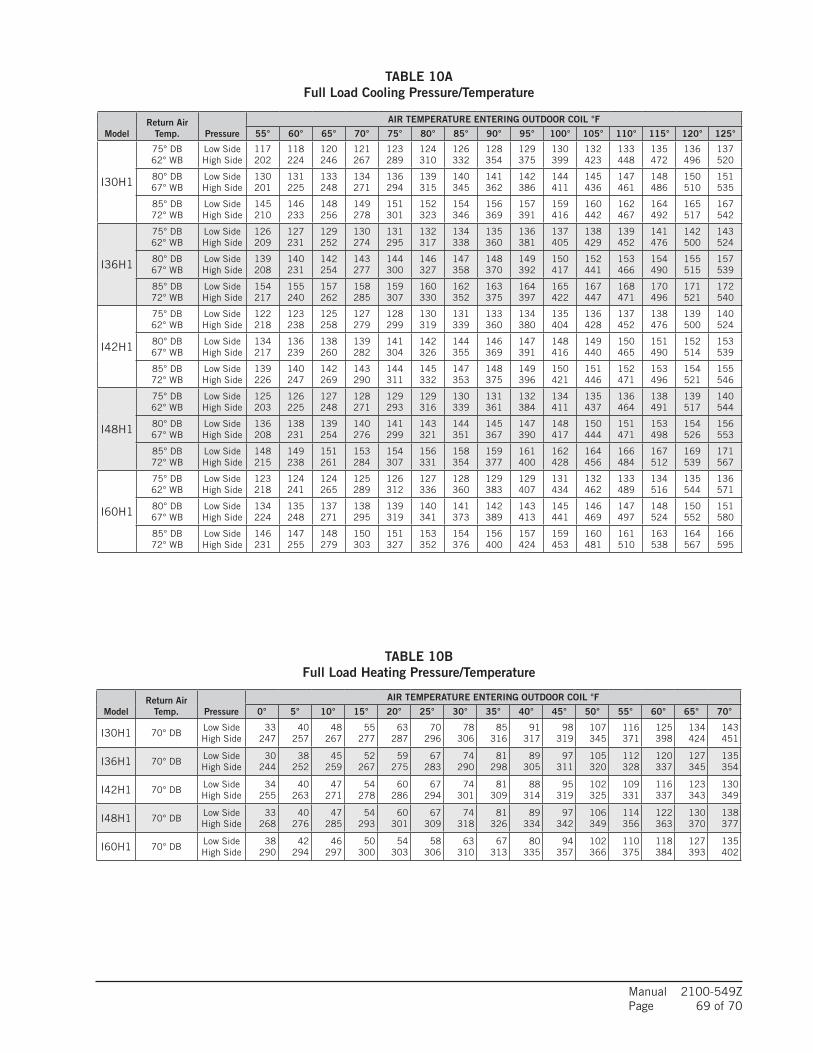
Manual 2100-549ZPage 69 of 70
TABLE 10A Full Load Cooling Pressure/Temperature
TABLE 10B Full Load Heating Pressure/Temperature
ModelReturn Air
Temp. Pressure
AIR TEMPERATURE ENTERING OUTDOOR COIL °F
55° 60° 65° 70° 75° 80° 85° 90° 95° 100° 105° 110° 115° 120° 125°
I30H1
75° DB62° WB
Low SideHigh Side
117202
118224
120246
121267
123289
124310
126332
128354
129375
130399
132423
133448
135472
136496
137520
80° DB67° WB
Low SideHigh Side
130201
131225
133248
134271
136294
139315
140345
141362
142386
144411
145436
147461
148486
150510
151535
85° DB72° WB
Low SideHigh Side
145210
146233
148256
149278
151301
152323
154346
156369
157391
159416
160442
162467
164492
165517
167542
I36H1
75° DB62° WB
Low SideHigh Side
126209
127231
129252
130274
131295
132317
134338
135360
136381
137405
138429
139452
141476
142500
143524
80° DB67° WB
Low SideHigh Side
139208
140231
142254
143277
144300
146327
147358
148370
149392
150417
152441
153466
154490
155515
157539
85° DB72° WB
Low SideHigh Side
154217
155240
157262
158285
159307
160330
162352
163375
164397
165422
167447
168471
170496
171521
172540
I42H1
75° DB62° WB
Low SideHigh Side
122218
123238
125258
127279
128299
130319
131339
133360
134380
135404
136428
137452
138476
139500
140524
80° DB67° WB
Low SideHigh Side
134217
136239
138260
139282
141304
142326
144355
146369
147391
148416
149440
150465
151490
152514
153539
85° DB72° WB
Low SideHigh Side
139226
140247
142269
143290
144311
145332
147353
148375
149396
150421
151446
152471
153496
154521
155546
I48H1
75° DB62° WB
Low SideHigh Side
125203
126225
127248
128271
129293
129316
130339
131361
132384
134411
135437
136464
138491
139517
140544
80° DB67° WB
Low SideHigh Side
136208
138231
139254
140276
141299
143321
144351
145367
147390
148417
150444
151471
153498
154526
156553
85° DB72° WB
Low SideHigh Side
148215
149238
151261
153284
154307
156331
158354
159377
161400
162428
164456
166484
167512
169539
171567
I60H1
75° DB62° WB
Low SideHigh Side
123218
124241
124265
125289
126312
127336
128360
129383
129407
131434
132462
133489
134516
135544
136571
80° DB67° WB
Low SideHigh Side
134224
135248
137271
138295
139319
140341
141373
142389
143413
145441
146469
147497
148524
150552
151580
85° DB72° WB
Low SideHigh Side
146231
147255
148279
150303
151327
153352
154376
156400
157424
159453
160481
161510
163538
164567
166595
ModelReturn Air
Temp. Pressure
AIR TEMPERATURE ENTERING OUTDOOR COIL °F
0° 5° 10° 15° 20° 25° 30° 35° 40° 45° 50° 55° 60° 65° 70°
I30H1 70° DBLow SideHigh Side
33247
40257
48267
55277
63287
70296
78306
85316
91317
98319
107345
116371
125398
134424
143451
I36H1 70° DBLow SideHigh Side
30244
38252
45259
52267
59275
67283
74290
81298
89305
97311
105320
112328
120337
127345
135354
I42H1 70° DBLow SideHigh Side
34255
40263
47271
54278
60286
67294
74301
81309
88314
95319
102325
109331
116337
123343
130349
I48H1 70° DBLow SideHigh Side
33268
40276
47285
54293
60301
67309
74318
81326
89334
97342
106349
114356
122363
130370
138377
I60H1 70° DBLow SideHigh Side
38290
42294
46297
50300
54303
58306
63310
67313
80335
94357
102366
110375
118384
127393
135402

Manual 2100-549ZPage 70 of 70
TABLE 11A Part Load Cooling Pressure/Temperature
TABLE 11B Part Load Heating Pressure/Temperature
ModelReturn Air
Temp. PressureAIR TEMPERATURE ENTERING OUTDOOR COIL °F
55° 60° 65° 70° 75° 80° 85° 90° 95° 100° 105° 110° 115° 120° 125°
I30H1
75° DB62° WB
Low SideHigh Side
127184
128206
129227
129249
130270
131292
132313
133334
134356
135380
137403
138427
140451
141475
143498
80° DB67° WB
Low SideHigh Side
141187
141209
142231
143252
143274
144293
144322
145338
146361
147385
149409
151433
152457
154481
156505
85° DB72° WB
Low SideHigh Side
154194
154216
155237
156259
156280
157302
157323
158344
159366
161390
162415
164439
166464
168488
170512
I36H1
75° DB62° WB
Low SideHigh Side
131188
133209
134230
136250
137271
139292
140313
142333
143354
144378
145403
146427
148452
149476
150500
80° DB67° WB
Low SideHigh Side
145191
146212
148233
149254
150275
152295
153323
154338
155359
156384
158409
159433
160458
161483
163508
85° DB72° WB
Low SideHigh Side
158198
159219
161240
162260
163281
164302
166323
167343
168364
169389
171414
172439
173464
175489
176515
I42H1
75° DB62° WB
Low SideHigh Side
126192
128212
130233
132253
134274
136294
138315
139335
141356
142379
143402
144426
145449
146472
147496
80° DB67° WB
Low SideHigh Side
140195
141216
143236
145257
146278
148299
150326
151340
153361
154384
155408
156432
157455
158479
159503
85° DB72° WB
Low SideHigh Side
144202
145223
147243
148264
150284
151304
152325
154345
155366
156390
157414
158438
159462
160486
161510
I48H1
75° DB62° WB
Low SideHigh Side
129183
130205
131226
132248
133269
133291
134313
135334
136356
137381
139407
140432
142458
143484
144509
80° DB67° WB
Low SideHigh Side
140187
141209
142230
144252
145274
146295
148324
149339
151361
152387
154413
155439
157465
158491
160517
85° DB72° WB
Low SideHigh Side
154189
155212
157234
158257
160280
161303
162325
164348
165371
167397
168424
170451
172477
173504
175530
I60H1
75° DB62° WB
Low SideHigh Side
127196
127218
128240
128261
129283
130305
130326
131348
131370
133396
134422
135448
136474
137500
139526
80° DB67° WB
Low SideHigh Side
137200
138222
139244
140266
142288
142310
143339
144353
146375
147402
148428
150454
151481
152507
154534
85° DB72° WB
Low SideHigh Side
152203
153226
153249
154271
155294
156317
157340
158363
159385
161412
162440
164467
165494
167521
168548
ModelReturn Air
Temp. PressureAIR TEMPERATURE ENTERING OUTDOOR COIL °F
0° 5° 10° 15° 20° 25° 30° 35° 40° 45° 50° 55° 60° 65° 70°
I30H1 70° DB Low SideHigh Side
40239
47249
54258
61268
68278
75288
83297
90307
97311
104315
115328
125341
135353
146366
156378
I36H1 70° DB Low SideHigh Side
36233
44241
51248
58255
65262
73270
80277
87284
96292
104299
114307
123315
133322
142330
152338
I42H1 70° DB Low SideHigh Side
37242
45250
52258
60265
67273
75281
82288
90296
96303
103309
110316
118323
126331
134338
142345
I48H1 70° DB Low SideHigh Side
35265
43271
51277
59282
67288
75293
83299
92305
98318
105331
115340
124348
134357
143365
153374
I60H1 70° DB Low SideHigh Side
38263
45272
52281
60291
67300
74309
82318
89327
96336
104345
113356
122366
131377
140387
149398


Page 1 of 41
I-TEC® Series Packaged Heat Pump
Models:
REPLACEMENT PARTS MANUAL
I30H1-AI30H1-BI30H1-C
I30H1DAI30H1DBI30H1DC
I36H1-AI36H1-BI36H1-C
I36H1DAI36H1DBI36H1DC
I42H1-AI42H1-BI42H1-C
I42H1DAI42H1DBI42H1DC
I48H1-AI48H1-BI48H1-C
I48H1DAI48H1DBI48H1DC
I60H1-AI60H1-BI60H1-C
I60H1DAI60H1DBI60H1DC
Description Page
Wiring Diagram Charts Matrix ....................................................................... 2 - 3Cabinet Components Exploded View ..............................................................4 Usage List ...................................................................5Painted Cabinet Components Exploded View ..............................................................6 Usage List ...................................................................7Functional Components Exploded View ..............................................................8 Usage List ....................................................................9 Usage List ...................................................................10Blower Assembly Exploded View .............................................................11 Usage List ...................................................................11Control Panel Components - 1 Phase Exploded View .............................................................12 Usage List ...................................................................13Control Panel Components - 3 Phase Exploded View .............................................................14 Usage List ...................................................................15Control Panel Components - 460V 3 Phase Exploded View .............................................................16 Usage List ...................................................................17Electric Heater Components Exploded View .............................................................18 Usage Lists ............................................................. 19 - 21Vent Box (Only) Components Exploded View .............................................................22 Usage List ...................................................................23CRV Components Exploded View .............................................................24 Usage List ...................................................................25Modulating CRV Components Exploded View .............................................................26 Usage List ...................................................................27
Description Page
Modulating CRV Control Panel Components Exploded View .............................................................28 Usage List ...................................................................29ERV Components Exploded View .............................................................30 Usage List ...................................................................31ERV Control Panel Components Exploded View .............................................................32 Usage List ...................................................................33ERV Cassette Components Exploded View .............................................................34 Usage List ...................................................................35CRV/ERV Blower Components Exploded View .............................................................36 Usage List ...................................................................37Sleeve Components Exploded View .............................................................38 Usage List ...................................................................39Riser Platform Components Exploded View .............................................................40 Usage List ...................................................................41
Bard Manufacturing Company, Inc. Bryan, Ohio 43506
www.bardhvac.com
Manual: 2110-1538JSupersedes: 2110-1538IDate: 11-17-21
General NotesRevised and/or additional pages may be issued from
time to time.
A complete and current manual consists of pages shown in the following contents section.
ImportantContact the installing and/or local Bard distributor for
all parts requirements. Be sure to have the complete model and serial number available from the unit rating plates.

Manual 2110-1538JPage 2 of 41
Model WiringDiagram Ventilation Package Wiring
Diagram Heater WiringDiagram
I30H1-A 4202-103
Commercial Room Ventilator 4204-103 0KW 4203-100Energy Recovery Ventilator 4204-108 5KW 4203-101
Economizer 4204-105 10KW 4203-103Modulating Commercial Room Ventilator 4204-106
I30H1-B 4202-203
Commercial Room Ventilator 4204-103 0KW 4203-200Energy Recovery Ventilator 4204-108 6KW 4203-201
Economizer 4204-105 9KW 4203-201Modulating Commercial Room Ventilator 4204-106
I30H1-C 4202-303
Commercial Room Ventilator 4204-103 0KW 4203-300Energy Recovery Ventilator 4204-108 6KW 4203-301
Economizer 4204-105 9KW 4203-301Modulating Commercial Room Ventilator 4204-106
I36H1-A 4202-103
Commercial Room Ventilator 4204-103 0KW 4203-100Energy Recovery Ventilator 4204-108 5KW 4203-101
Economizer 4204-105 10KW 4203-103Modulating Commercial Room Ventilator 4204-106 15KW 4203-104
I36H1-B 4202-203
Commercial Room Ventilator 4204-103 0KW 4203-200Energy Recovery Ventilator 4204-108 6KW 4203-201
Economizer 4204-105 9KW 4203-201Modulating Commercial Room Ventilator 4204-106 15KW 4203-202
I36H1-C 4202-303
Commercial Room Ventilator 4204-103 0KW 4203-300Energy Recovery Ventilator 4204-108 6KW 4203-301
Economizer 4204-105 9KW 4203-301Modulating Commercial Room Ventilator 4204-106 15KW 4203-302
I42H1-A 4202-103
Commercial Room Ventilator 4204-103 0KW 4203-100Energy Recovery Ventilator 4204-108 5KW 4203-101
Economizer 4204-105 10KW 4203-103Modulating Commercial Room Ventilator 4204-106 15KW 4203-104
I42H1-B 4202-203
Commercial Room Ventilator 4204-103 0KW 4203-200Energy Recovery Ventilator 4204-108 6KW 4203-201
Economizer 4204-105 9KW 4203-201Modulating Commercial Room Ventilator 4204-106 15KW 4203-202
I42H1-C 4202-303
Commercial Room Ventilator 4204-103 0KW 4203-300Energy Recovery Ventilator 4204-108 6KW 4203-301
Economizer 4204-105 9KW 4203-301Modulating Commercial Room Ventilator 4204-106 15KW 4203-302
I48H1-A 4202-103
Commercial Room Ventilator 4204-103 0KW 4203-100Energy Recovery Ventilator 4204-108 4KW 4203-101
Economizer 4204-105 5KW 4203-102Modulating Commercial Room Ventilator 4204-106 10KW 4203-103
15KW 4203-10420KW 4203-105
I48H1-B 4202-203
Commercial Room Ventilator 4204-103 0KW 4203-200Energy Recovery Ventilator 4204-108 6KW 4203-201
Economizer 4204-105 9KW 4203-201Modulating Commercial Room Ventilator 4204-106 15KW 4203-202
18KW 4203-202
I48H1-C 4202-303
Commercial Room Ventilator 4204-103 0KW 4203-300Energy Recovery Ventilator 4204-108 6KW 4203-301
Economizer 4204-105 9KW 4203-301Modulating Commercial Room Ventilator 4204-106 15KW 4203-302
18KW 4203-302
I60H1-A 4202-103
Commercial Room Ventilator 4204-103 0KW 4203-100Energy Recovery Ventilator 4204-108 4KW 4203-101
Economizer 4204-105 5KW 4203-102Modulating Commercial Room Ventilator 4204-106 10KW 4203-103
15KW 4203-10420KW 4203-105
I60H1-B 4202-203
Commercial Room Ventilator 4204-103 0KW 4203-200Energy Recovery Ventilator 4204-108 6KW 4203-201
Economizer 4204-105 9KW 4203-201Modulating Commercial Room Ventilator 4204-106 15KW 4203-202
18KW 4203-203
I60H1-C 4202-303
Commercial Room Ventilator 4204-103 0KW 4203-300Energy Recovery Ventilator 4204-108 6KW 4203-301
Economizer 4204-105 9KW 4203-301Modulating Commercial Room Ventilator 4204-106 15KW 4203-302
18KW 4203-302
I**H1 SERIES WIRING DIAGRAM MATRIX

Manual 2110-1538J Page 3 of 41
Model WiringDiagram Ventilation Package Wiring
Diagram Heater WiringDiagram
I30H1DA 4202-104
Commercial Room Ventilator 4204-103 0KW 4203-100Energy Recovery Ventilator 4204-108 5KW 4203-101
Economizer 4204-105 10KW 4203-103Modulating Commercial Room Ventilator 4204-106
I30H1DB 4202-204
Commercial Room Ventilator 4204-103 0KW 4203-200Energy Recovery Ventilator 4204-108 6KW 4203-201
Economizer 4204-105 9KW 4203-201Modulating Commercial Room Ventilator 4204-106
I30H1DC 4202-304
Commercial Room Ventilator 4204-103 0KW 4203-300Energy Recovery Ventilator 4204-108 6KW 4203-301
Economizer 4204-105 9KW 4203-301Modulating Commercial Room Ventilator 4204-106
I36H1DA 4202-104
Commercial Room Ventilator 4204-103 0KW 4203-100Energy Recovery Ventilator 4204-108 5KW 4203-101
Economizer 4204-105 10KW 4203-103Modulating Commercial Room Ventilator 4204-106 15KW 4203-104
I36H1DB 4202-204
Commercial Room Ventilator 4204-103 0KW 4203-200Energy Recovery Ventilator 4204-108 6KW 4203-201
Economizer 4204-105 9KW 4203-201Modulating Commercial Room Ventilator 4204-106 15KW 4203-202
I36H1DC 4202-304
Commercial Room Ventilator 4204-103 0KW 4203-300Energy Recovery Ventilator 4204-108 6KW 4203-301
Economizer 4204-105 9KW 4203-301Modulating Commercial Room Ventilator 4204-106 15KW 4203-302
I42H1DA 4202-104
Commercial Room Ventilator 4204-103 0KW 4203-100Energy Recovery Ventilator 4204-108 5KW 4203-101
Economizer 4204-105 10KW 4203-103Modulating Commercial Room Ventilator 4204-106 15KW 4203-104
I42H1DB 4202-204
Commercial Room Ventilator 4204-103 0KW 4203-200Energy Recovery Ventilator 4204-108 6KW 4203-201
Economizer 4204-105 9KW 4203-201Modulating Commercial Room Ventilator 4204-106 15KW 4203-202
I42H1DC 4202-304
Commercial Room Ventilator 4204-103 0KW 4203-300Energy Recovery Ventilator 4204-108 6KW 4203-301
Economizer 4204-105 9KW 4203-301Modulating Commercial Room Ventilator 4204-106 15KW 4203-302
I48H1DA 4202-104
Commercial Room Ventilator 4204-103 0KW 4203-100Energy Recovery Ventilator 4204-108 4KW 4203-101
Economizer 4204-105 5KW 4203-102Modulating Commercial Room Ventilator 4204-106 10KW 4203-103
15KW 4203-10420KW 4203-105
I48H1DB 4202-204
Commercial Room Ventilator 4204-103 0KW 4203-200Energy Recovery Ventilator 4204-108 6KW 4203-201
Economizer 4204-105 9KW 4203-201Modulating Commercial Room Ventilator 4204-106 15KW 4203-202
18KW 4203-202
I48H1DC 4202-304
Commercial Room Ventilator 4204-103 0KW 4203-300Energy Recovery Ventilator 4204-108 6KW 4203-301
Economizer 4204-105 9KW 4203-301Modulating Commercial Room Ventilator 4204-106 15KW 4203-302
18KW 4203-302
I60H1DA 4202-104
Commercial Room Ventilator 4204-103 0KW 4203-100Energy Recovery Ventilator 4204-108 4KW 4203-101
Economizer 4204-105 5KW 4203-102Modulating Commercial Room Ventilator 4204-106 10KW 4203-103
15KW 4203-10420KW 4203-105
I60H1DB 4202-204
Commercial Room Ventilator 4204-103 0KW 4203-200Energy Recovery Ventilator 4204-108 6KW 4203-201
Economizer 4204-105 9KW 4203-201Modulating Commercial Room Ventilator 4204-106 15KW 4203-202
18KW 4203-203
I60H1DC 4202-304
Commercial Room Ventilator 4204-103 0KW 4203-300Energy Recovery Ventilator 4204-108 6KW 4203-301
Economizer 4204-105 9KW 4203-301Modulating Commercial Room Ventilator 4204-106 15KW 4203-302
18KW 4203-302
I**H1 SERIES WIRING DIAGRAM MATRIX

Manual 2110-1538JPage 4 of 41
CABINET COMPONENTS
24
32
40
34
41
42
SEXP-619A18
24
30
25
1
3
2
13
5 7 8
9
4
10
6
12
915
1314
11
171920
35
21
23
38
22
36
33
29
39
37
9
262827
31
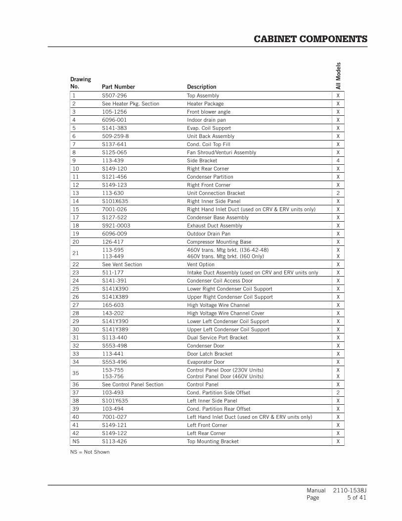
Manual 2110-1538J Page 5 of 41
DrawingNo. Part Number Description A
ll M
odel
s
CABINET COMPONENTS
1 S507-296 Top Assembly X
2 See Heater Pkg. Section Heater Package X
3 105-1256 Front blower angle X
4 6096-001 Indoor drain pan X
5 S141-383 Evap. Coil Support X
6 509-259-8 Unit Back Assembly X
7 S137-641 Cond. Coil Top Fill X
8 S125-065 Fan Shroud/Venturi Assembly X
9 113-439 Side Bracket 4
10 S149-120 Right Rear Corner X
11 S121-456 Condenser Partition X
12 S149-123 Right Front Corner X
13 113-630 Unit Connection Bracket 2
14 S101X635 Right Inner Side Panel X
15 7001-026 Right Hand Inlet Duct (used on CRV & ERV units only) X
17 S127-522 Condenser Base Assembly X
18 S921-0003 Exhaust Duct Assembly X
19 6096-009 Outdoor Drain Pan X
20 126-417 Compressor Mounting Base X
21113-595113-449
460V trans. Mtg brkt. (I36-42-48)460V trans. Mtg brkt. (I60 Only)
XX
22 See Vent Section Vent Option X
23 511-177 Intake Duct Assembly (used on CRV and ERV units only X
24 S141-391 Condenser Coil Access Door X
25 S141X390 Lower Right Condenser Coil Support X
26 S141X389 Upper Right Condenser Coil Support X
27 165-603 High Voltage Wire Channel X
28 143-202 High Voltage Wire Channel Cover X
29 S141Y390 Lower Left Condenser Coil Support X
30 S141Y389 Upper Left Condenser Coil Support X
31 S113-440 Dual Service Port Bracket X
32 S553-498 Condenser Door X
33 113-441 Door Latch Bracket X
34 S553-496 Evaporator Door X
35153-755153-756
Control Panel Door (230V Units)Control Panel Door (460V Units)
XX
36 See Control Panel Section Control Panel X
37 103-493 Cond. Partition Side Offset 2
38 S101Y635 Left Inner Side Panel X
39 103-494 Cond. Partition Rear Offset X
40 7001-027 Left Hand Inlet Duct (used on CRV & ERV units only) X
41 S149-121 Left Front Corner X
42 S149-122 Left Rear Corner X
NS S113-426 Top Mounting Bracket X
NS = Not Shown
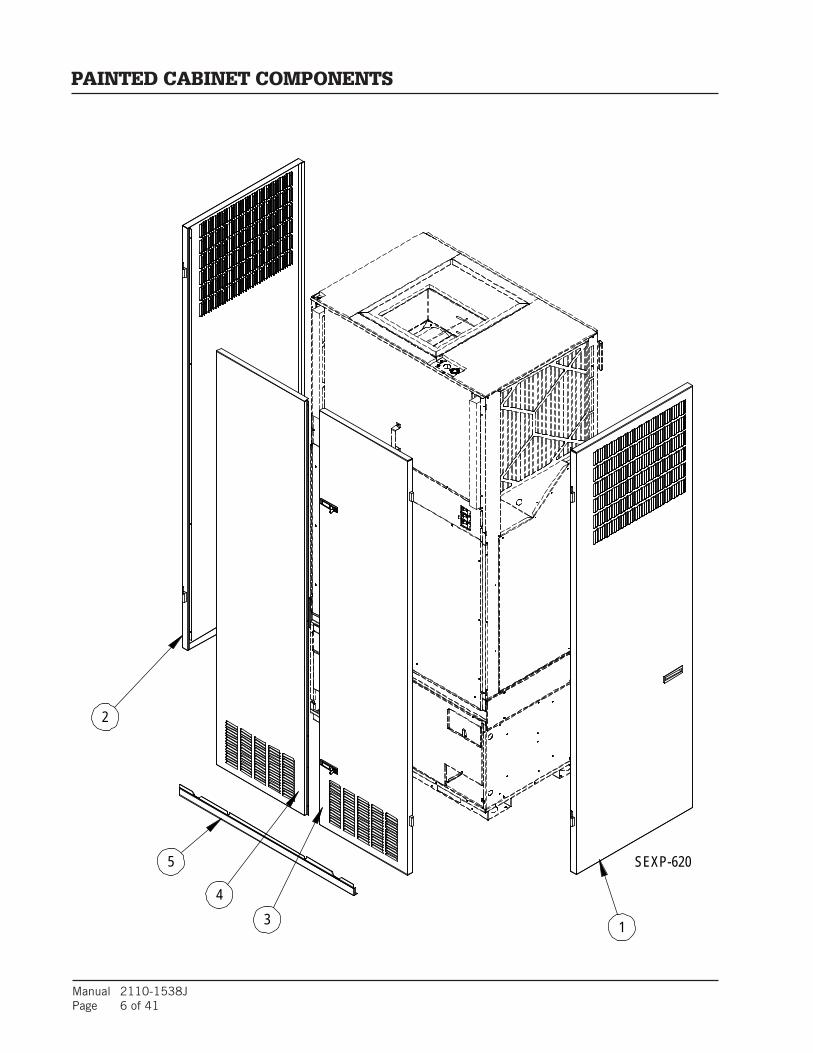
Manual 2110-1538JPage 6 of 41
PAINTED CABINET COMPONENTS
34
1
5
2
SEXP-620

Manual 2110-1538J Page 7 of 41
DrawingNo. Part Number Description A
ll M
odel
s
1 501-636-* Right Side X
2 501-637-* Left Side X
3 S553-500-* Right Front Door X
4 S553-499-* Left Front Door X
5 115-206-* Front Unit Trim X
NS 5451-031 Hinge Spacer (Black Nylon) 2
PAINTED CABINET COMPONENTS
* Exterior cabinet parts are manufactured with various paint color options. To ensure the proper paint color is received, reference the following codes:
Beige -X White -1 Buckeye Gray -4
NS = Not Shown
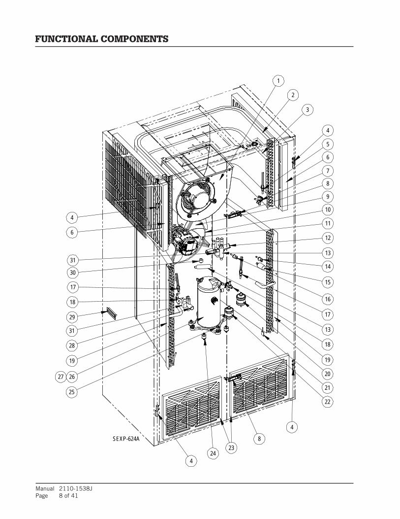
Manual 2110-1538JPage 8 of 41
25
13
4
31
31
21
1
2
3
4
5
4
7
8
6
12
9
11
14
15
16
17
18
17
30
22
19
20
8
4
13
26
10
18
6
SEXP-624A
28
21
27
24
19
23
29
FUNCTIONAL COMPONENTS

Manual 2110-1538J Page 9 of 41
Dra
win
gN
o.P
art
Num
ber
Des
crip
tion
I30H1-A
I30H1-B
I30H1-C
I30H1DA
I30H1DB
I30H1DC
I36H1-A
I36H1-B
I36H1-C
I36H1DA
I36H1DB
I36H1DC
I42H1-A
I42H1-B
I42H1-C
I42H1DA
I42H1DB
I42H1DC
I48H1-A
I48H1-B
I48H1-C
I48H1DA
I48H1DB
I48H1DC
I60H1-A
I60H1-B
I60H1-C
I60H1DA
I60H1DB
I60H1DC
1
51
54
-01
6-0
09
0B
X
Com
plet
e B
low
er A
ssem
bly
See
Blo
wer
sec
tion
for
in
divi
dual
com
pone
nts
XX
XX
XX
51
54
-01
7-0
08
9B
XX
XX
XX
X
51
54
-01
7-0
08
8B
XX
XX
XX
X
51
54
-01
7-0
08
7B
XX
XX
XX
X
51
54
-01
8-0
08
1B
XX
XX
XX
X
2
50
60
-17
4B
X
Eva
pora
tor
Coi
l
XX
XX
XX
50
60
-16
8B
XX
XX
XX
XX
XX
XX
XX
XX
XX
X
50
60
-17
5B
XX
XX
XX
X
3
50
51
-17
3B
X
Deh
umid
ifica
tion
Reh
eat
Coi
l
XX
X
50
51
-17
4B
XX
XX
XX
X
50
51
-17
5B
XX
XX
XX
X
45
40
0-0
06
Pol
ymid
e Li
ft-O
ff H
inge
44
44
44
44
44
44
44
44
44
44
44
44
44
44
44
5
56
25
-01
4
Dis
trib
utor
XX
XX
XX
56
25
-00
7X
XX
XX
XX
XX
XX
XX
XX
XX
X
56
25
-00
8X
XX
XX
X
67
00
4-0
50
70
04
-05
17
00
4-0
53
ME
RV
8 F
ilter
ME
RV
11
Filt
erM
ER
V 1
3 F
ilter
22
22
22
22
22
22
22
22
22
22
22
22
22
22
22
7
56
51
-21
0
Exp
ansi
on V
alve
XX
XX
XX
56
51
-21
2X
XX
XX
X
56
51
-21
1X
XX
XX
XX
XX
XX
X
56
51
-24
1X
XX
XX
X
81
17
1-0
63
Lock
able
Lat
ch2
22
22
22
22
22
22
22
22
22
22
22
22
22
22
2
95
15
1-0
58
Fan
Bla
deX
XX
XX
XX
XX
XX
XX
XX
XX
XX
XX
XX
XX
XX
XX
X
10
82
00
-04
5Fa
n M
ount
XX
XX
XX
XX
XX
XX
XX
XX
XX
XX
XX
XX
XX
XX
XX
11
S8
10
5-0
58
-01
09
Pro
gram
med
Out
door
Mot
or
XX
XX
XX
S8
10
5-0
58
-00
95
XX
XX
XX
XX
XX
XX
S8
10
6-0
54
-00
96
XX
XX
XX
XX
XX
XX
12
56
50
-03
8
Rev
ersi
ng V
alve
XX
XX
XX
56
50
-03
9X
XX
XX
XX
XX
XX
X
56
50
-04
0X
XX
XX
XX
XX
XX
X
13
56
51
-21
9C
heck
Val
ve2
22
22
22
22
22
22
22
14
84
06
-14
2H
igh
Pres
sure
Sw
itch,
650
PSI
GX
XX
XX
XX
XX
XX
XX
XX
XX
XX
XX
XX
XX
XX
XX
X
15
84
06
-11
2Lo
w A
mbi
ent
Con
trol
XX
XX
XX
XX
XX
XX
XX
XX
XX
XX
XX
XX
XX
XX
XX
16
84
06
-13
5Lo
w P
ress
ure
Sw
itch
XX
XX
XX
XX
XX
XX
XX
XX
XX
XX
XX
XX
XX
XX
XX
17
56
25
-01
3D
istr
ibut
or2
22
22
22
22
22
22
22
22
2
56
25
-00
72
22
22
22
22
22
2
18
56
51
-21
7
Exp
ansi
on V
alve
22
22
22
22
22
22
56
51
-21
82
22
22
22
22
22
2
56
51
-20
02
22
22
2
19
50
51
-19
0B
X
Con
dens
er C
oil
22
22
22
50
51
-18
9B
X2
22
22
22
22
22
2
50
51
-19
1B
X2
22
22
22
22
22
2
20
52
01
-01
9Fi
lter
-Dri
erX
XX
XX
X
52
01
-02
0X
XX
XX
XX
XX
XX
XX
XX
XX
XX
XX
XX
X
FUNCTIONAL COMPONENTS

Manual 2110-1538JPage 10 of 41
Dra
win
gN
o.P
art
Num
ber
Des
crip
tion
I30H1-A
I30H1-B
I30H1-C
I30H1DA
I30H1DB
I30H1DC
I36H1-A
I36H1-B
I36H1-C
I36H1DA
I36H1DB
I36H1DC
I42H1-A
I42H1-B
I42H1-C
I42H1DA
I42H1DB
I42H1DC
I48H1-A
I48H1-B
I48H1-C
I48H1DA
I48H1DB
I48H1DC
I60H1-A
I60H1-B
I60H1-C
I60H1DA
I60H1DB
I60H1DC
22
52
20
-01
3P
uls
atio
n D
ampen
er/M
uffl
erX
XX
XX
XX
XX
XX
XX
XX
XX
XX
XX
XX
XX
XX
XX
X
23
70
04
-00
3Filte
r2
22
22
22
22
22
22
22
22
22
22
22
22
22
22
2
24
80
01
-01
3C
ompre
ssor
Gro
mm
et4
44
44
44
44
44
44
44
44
44
44
44
44
44
44
4
25
10
12
-32
8C
ompre
ssor
Bol
t4
44
44
44
44
44
44
44
44
44
44
44
44
44
44
4
26
80
00
-38
8
Com
pre
ssor
XX
80
00
-38
9X
X
80
00
-39
0X
X
80
00
-37
9X
X
80
00
-38
0X
X
80
00
-38
1X
X
80
00
-39
1X
X
80
00
-39
2X
X
80
00
-39
3X
X
80
00
-38
2X
X
80
00
-38
3X
X
80
00
-38
4X
X
80
00
-42
4X
X
80
00
-42
5X
X
80
00
-42
6X
X
27
80
02
-01
2C
ompr
esso
r S
ound
Cov
erX
XX
XX
XX
XX
XX
XX
XX
XX
X
80
02
-01
3X
XX
XX
XX
XX
XX
X
28
56
50
-05
1D
ehum
. Va
lve,
4-P
ipe
XX
XX
XX
XX
XX
XX
XX
X
29
11
71
-06
0Flu
sh P
last
ic D
oor
Pull
22
22
22
22
22
22
22
22
22
22
22
22
22
22
22
30
54
51
-01
8M
otor
Mou
nt
Gro
mm
ent
22
22
22
22
22
22
22
22
22
22
22
22
22
22
22
31
56
50
-04
6R
ev.
Valv
e S
olen
oid -
Bla
ck
casi
ng
XX
X2
22
XX
X2
22
XX
X2
22
XX
X2
22
XX
X2
22
NS
60
94
-01
13
/4"
Bar
bed
Dra
in P
an
Fit
ting
44
44
44
44
44
44
44
44
44
44
44
44
44
44
44
NS
60
01
-01
6N
ylon
Bar
bed
Tee
X
XX
XX
XX
XX
XX
XX
XX
XX
XX
XX
XX
XX
XX
XX
X
NS
79
50
-02
11
" H
ose
Cla
mp
88
88
88
88
88
88
88
88
88
88
88
88
88
88
88
NS
91
0-1
97
7E
vap O
verfl
ow S
wit
ch A
ss'y
XX
XX
XX
XX
XX
XX
XX
XX
XX
XX
XX
XX
XX
XX
XX
NS
60
31
-00
9C
orem
ax V
alve
Cor
eX
XX
XX
XX
XX
XX
XX
XX
XX
XX
XX
XX
XX
XX
XX
X
FUNCTIONAL COMPONENTS
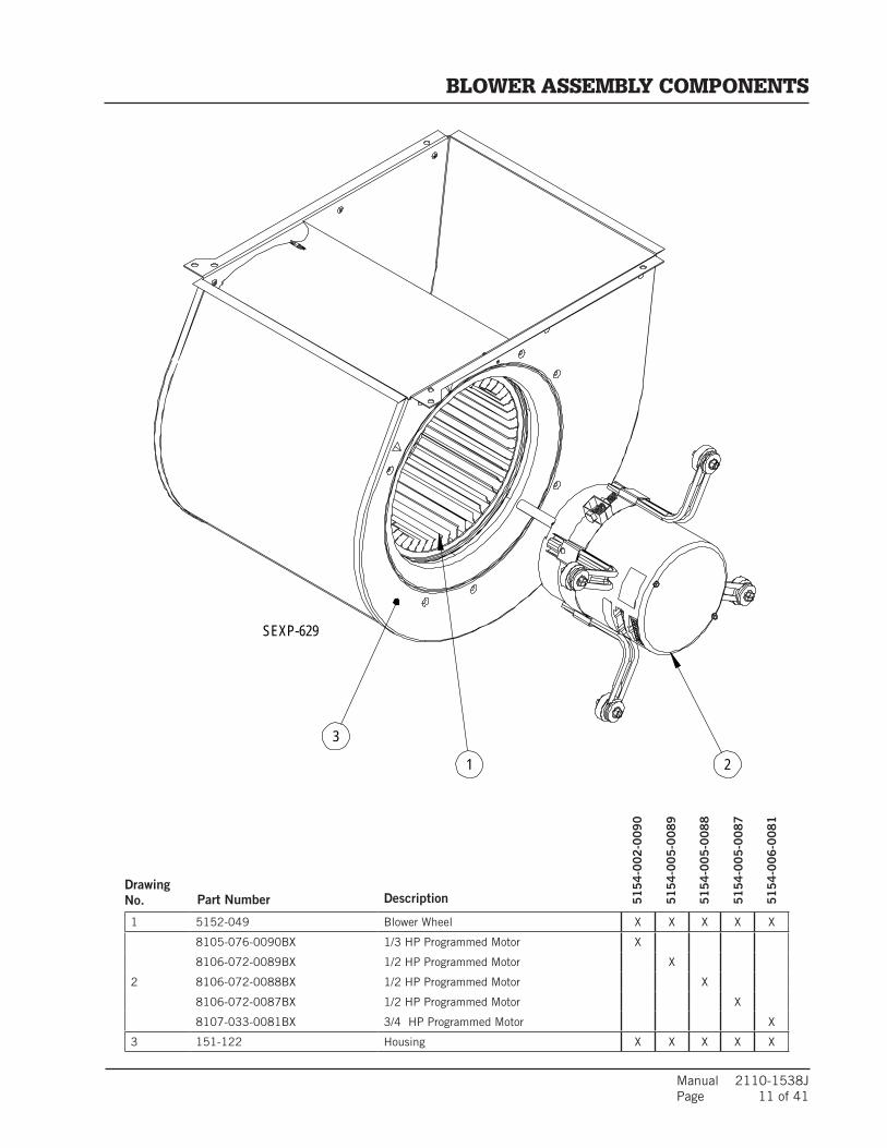
Manual 2110-1538J Page 11 of 41
DrawingNo. Part Number Description
1 5152-049 Blower Wheel X X X X X
2
8105-076-0090BX 1/3 HP Programmed Motor X
8106-072-0089BX 1/2 HP Programmed Motor X
8106-072-0088BX 1/2 HP Programmed Motor X
8106-072-0087BX 1/2 HP Programmed Motor X
8107-033-0081BX 3/4 HP Programmed Motor X
3 151-122 Housing X X X X X
51
54
-00
2-0
09
0
51
54
-00
5-0
08
9
51
54
-00
5-0
08
8
51
54
-00
5-0
08
7
51
54
-00
6-0
08
1
SEXP-629
3
1 2
BLOWER ASSEMBLY COMPONENTS
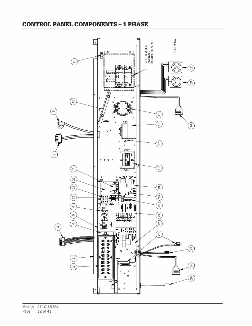
Manual 2110-1538JPage 12 of 41
98
3
1423
1413
12
SEXP
-958
A
24
271
284
26
710
11 CO
MP
ON
EN
TS
2221
1918
1716
15
PA
CK
AG
E
5
2025
SE
E H
EA
TER
26
29
CONTROL PANEL COMPONENTS – 1 PHASE
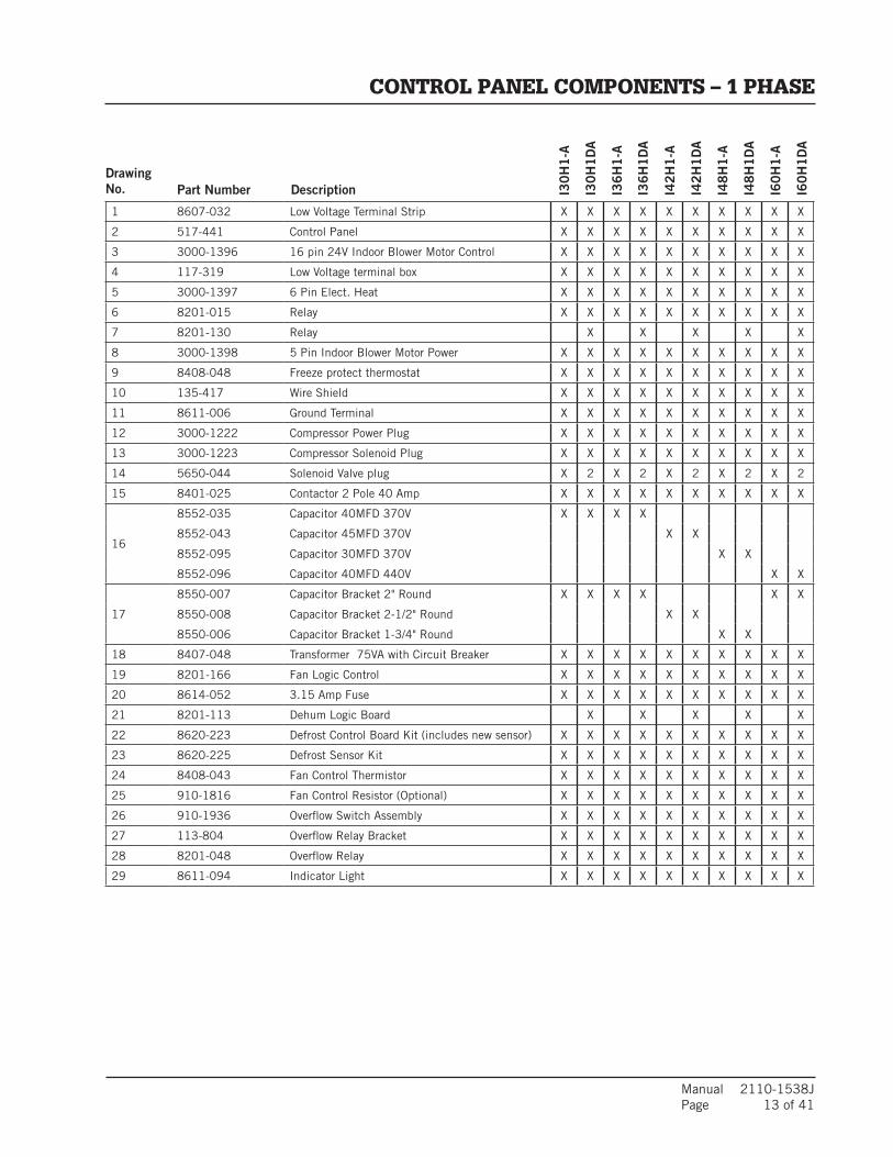
Manual 2110-1538J Page 13 of 41
DrawingNo. Part Number Description I3
0H
1-A
I30
H1
DA
I36
H1
-A
I36
H1
DA
I42
H1
-A
I42
H1
DA
I48
H1
-A
I48
H1
DA
I60
H1
-A
I60
H1
DA
1 8607-032 Low Voltage Terminal Strip X X X X X X X X X X
2 517-441 Control Panel X X X X X X X X X X
3 3000-1396 16 pin 24V Indoor Blower Motor Control X X X X X X X X X X
4 117-319 Low Voltage terminal box X X X X X X X X X X
5 3000-1397 6 Pin Elect. Heat X X X X X X X X X X
6 8201-015 Relay X X X X X X X X X X
7 8201-130 Relay X X X X X
8 3000-1398 5 Pin Indoor Blower Motor Power X X X X X X X X X X
9 8408-048 Freeze protect thermostat X X X X X X X X X X
10 135-417 Wire Shield X X X X X X X X X X
11 8611-006 Ground Terminal X X X X X X X X X X
12 3000-1222 Compressor Power Plug X X X X X X X X X X
13 3000-1223 Compressor Solenoid Plug X X X X X X X X X X
14 5650-044 Solenoid Valve plug X 2 X 2 X 2 X 2 X 2
15 8401-025 Contactor 2 Pole 40 Amp X X X X X X X X X X
16
8552-035 Capacitor 40MFD 370V X X X X
8552-043 Capacitor 45MFD 370V X X
8552-095 Capacitor 30MFD 370V X X
8552-096 Capacitor 40MFD 440V X X
17
8550-007 Capacitor Bracket 2" Round X X X X X X
8550-008 Capacitor Bracket 2-1/2" Round X X
8550-006 Capacitor Bracket 1-3/4" Round X X
18 8407-048 Transformer 75VA with Circuit Breaker X X X X X X X X X X
19 8201-166 Fan Logic Control X X X X X X X X X X
20 8614-052 3.15 Amp Fuse X X X X X X X X X X
21 8201-113 Dehum Logic Board X X X X X
22 8620-223 Defrost Control Board Kit (includes new sensor) X X X X X X X X X X
23 8620-225 Defrost Sensor Kit X X X X X X X X X X
24 8408-043 Fan Control Thermistor X X X X X X X X X X
25 910-1816 Fan Control Resistor (Optional) X X X X X X X X X X
26 910-1936 Overflow Switch Assembly X X X X X X X X X X
27 113-804 Overflow Relay Bracket X X X X X X X X X X
28 8201-048 Overflow Relay X X X X X X X X X X
29 8611-094 Indicator Light X X X X X X X X X X
CONTROL PANEL COMPONENTS – 1 PHASE

Manual 2110-1538JPage 14 of 41
98
3
1422
1314
12
SEXP
-959
A
23
17
14
26
710
11 CO
MP
ON
EN
TS
26
2018
16
5
1521
1924
PA
CK
AG
E
27
SE
E H
EA
TER
25
28
CONTROL PANEL COMPONENTS – 3 PHASE
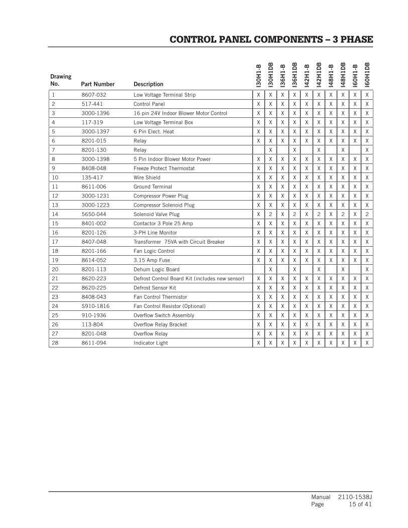
Manual 2110-1538J Page 15 of 41
DrawingNo. Part Number Description I3
0H
1-B
I30
H1
DB
I36
H1
-B
I36
H1
DB
I42
H1
-B
I42
H1
DB
I48
H1
-B
I48
H1
DB
I60
H1
-B
I60
H1
DB
1 8607-032 Low Voltage Terminal Strip X X X X X X X X X X
2 517-441 Control Panel X X X X X X X X X X
3 3000-1396 16 pin 24V Indoor Blower Motor Control X X X X X X X X X X
4 117-319 Low Voltage Terminal Box X X X X X X X X X X
5 3000-1397 6 Pin Elect. Heat X X X X X X X X X X
6 8201-015 Relay X X X X X X X X X X
7 8201-130 Relay X X X X X
8 3000-1398 5 Pin Indoor Blower Motor Power X X X X X X X X X X
9 8408-048 Freeze Protect Thermostat X X X X X X X X X X
10 135-417 Wire Shield X X X X X X X X X X
11 8611-006 Ground Terminal X X X X X X X X X X
12 3000-1231 Compressor Power Plug X X X X X X X X X X
13 3000-1223 Compressor Solenoid Plug X X X X X X X X X X
14 5650-044 Solenoid Valve Plug X 2 X 2 X 2 X 2 X 2
15 8401-002 Contactor 3 Pole 25 Amp X X X X X X X X X X
16 8201-126 3-PH Line Monitor X X X X X X X X X X
17 8407-048 Transformer 75VA with Circuit Breaker X X X X X X X X X X
18 8201-166 Fan Logic Control X X X X X X X X X X
19 8614-052 3.15 Amp Fuse X X X X X X X X X X
20 8201-113 Dehum Logic Board X X X X X
21 8620-223 Defrost Control Board Kit (includes new sensor) X X X X X X X X X X
22 8620-225 Defrost Sensor Kit X X X X X X X X X X
23 8408-043 Fan Control Thermistor X X X X X X X X X X
24 S910-1816 Fan Control Resistor (Optional) X X X X X X X X X X
25 910-1936 Overflow Switch Assembly X X X X X X X X X X
26 113-804 Overflow Relay Bracket X X X X X X X X X X
27 8201-048 Overflow Relay X X X X X X X X X X
28 8611-094 Indicator Light X X X X X X X X X X
CONTROL PANEL COMPONENTS – 3 PHASE
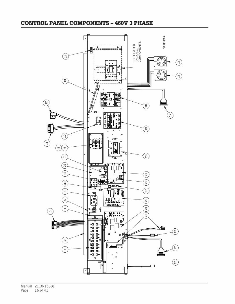
Manual 2110-1538JPage 16 of 41
3
1725
1211
16
17
1526
SEXP
-960
A
8
729
14
26
3010
1314
CO
MP
ON
EN
TS
2423
2120
1918
95
PA
CK
AG
E
2227
SE
E H
EA
TER
28
31
CONTROL PANEL COMPONENTS – 460V 3 PHASE
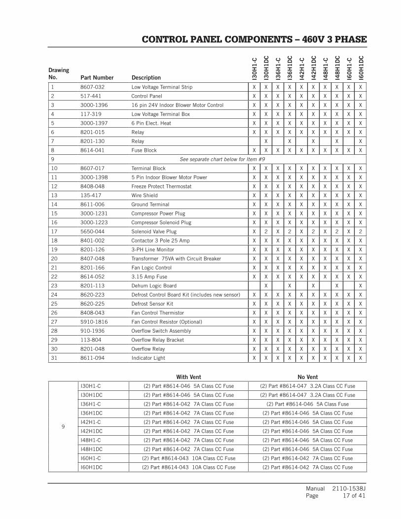
Manual 2110-1538J Page 17 of 41
DrawingNo. Part Number Description I3
0H
1-C
I30
H1
DC
I36
H1
-C
I36
H1
DC
I42
H1
-C
I42
H1
DC
I48
H1
-C
I48
H1
DC
I60
H1
-C
I60
H1
DC
With Vent No Vent
1 8607-032 Low Voltage Terminal Strip X X X X X X X X X X
2 517-441 Control Panel X X X X X X X X X X
3 3000-1396 16 pin 24V Indoor Blower Motor Control X X X X X X X X X X
4 117-319 Low Voltage Terminal Box X X X X X X X X X X
5 3000-1397 6 Pin Elect. Heat X X X X X X X X X X
6 8201-015 Relay X X X X X X X X X X
7 8201-130 Relay X X X X X
8 8614-041 Fuse Block X X X X X X X X X X
9 See separate chart below for Item #9
10 8607-017 Terminal Block X X X X X X X X X X
11 3000-1398 5 Pin Indoor Blower Motor Power X X X X X X X X X X
12 8408-048 Freeze Protect Thermostat X X X X X X X X X X
13 135-417 Wire Shield X X X X X X X X X X
14 8611-006 Ground Terminal X X X X X X X X X X
15 3000-1231 Compressor Power Plug X X X X X X X X X X
16 3000-1223 Compressor Solenoid Plug X X X X X X X X X X
17 5650-044 Solenoid Valve Plug X 2 X 2 X 2 X 2 X 2
18 8401-002 Contactor 3 Pole 25 Amp X X X X X X X X X X
19 8201-126 3-PH Line Monitor X X X X X X X X X X
20 8407-048 Transformer 75VA with Circuit Breaker X X X X X X X X X X
21 8201-166 Fan Logic Control X X X X X X X X X X
22 8614-052 3.15 Amp Fuse X X X X X X X X X X
23 8201-113 Dehum Logic Board X X X X X
24 8620-223 Defrost Control Board Kit (includes new sensor) X X X X X X X X X X
25 8620-225 Defrost Sensor Kit X X X X X X X X X X
26 8408-043 Fan Control Thermistor X X X X X X X X X X
27 S910-1816 Fan Control Resistor (Optional) X X X X X X X X X X
28 910-1936 Overflow Switch Assembly X X X X X X X X X X
29 113-804 Overflow Relay Bracket X X X X X X X X X X
30 8201-048 Overflow Relay X X X X X X X X X X
31 8611-094 Indicator Light X X X X X X X X X X
9
I30H1-C (2) Part #8614-046 5A Class CC Fuse (2) Part #8614-047 3.2A Class CC Fuse
I30H1DC (2) Part #8614-046 5A Class CC Fuse (2) Part #8614-047 3.2A Class CC Fuse
I36H1-C (2) Part #8614-042 7A Class CC Fuse (2) Part #8614-046 5A Class Fuse
I36H1DC (2) Part #8614-042 7A Class CC Fuse (2) Part #8614-046 5A Class CC Fuse
I42H1-C (2) Part #8614-042 7A Class CC Fuse (2) Part #8614-046 5A Class CC Fuse
I42H1DC (2) Part #8614-042 7A Class CC Fuse (2) Part #8614-046 5A Class CC Fuse
I48H1-C (2) Part #8614-042 7A Class CC Fuse (2) Part #8614-046 5A Class CC Fuse
I48H1DC (2) Part #8614-042 7A Class CC Fuse (2) Part #8614-046 5A Class CC Fuse
I60H1-C (2) Part #8614-043 10A Class CC Fuse (2) Part #8614-042 7A Class CC Fuse
I60H1DC (2) Part #8614-043 10A Class CC Fuse (2) Part #8614-042 7A Class CC Fuse
CONTROL PANEL COMPONENTS – 460V 3 PHASE

Manual 2110-1538JPage 18 of 41
11
13
SEXP-630 12
7
14
8
7 109
6
15
12
LOCATED IN UNITCONTROL PANEL 460V Units - Toggle Disconnect "C"
3
5
3
4
2
1
ELECTRIC HEATER COMPONENTS

Manual 2110-1538J Page 19 of 41
DrawingNo. Part No. Description I3
0H
1-A
0Z,
I3
0H
1D
A0
Z
I30
H1
-A0
5,
I30
H1
DA
05
I30
H1
-A1
0,
I30
H1
DA
10
I36
H1
-A0
Z, I
36
H1
DA
0Z
I36
H1
-A0
5,
I36
H1
DA
05
I36
H1
-A1
0,
I36
H1
DA
10
I36
H1
-A1
5,
I36
H1
DA
15
I42
H1
-A0
Z, I
42
H1
DA
0Z
I42
H1
-A0
5,
I42
H1
DA
05
I42
H1
-A1
0,
I42
H1
DA
10
I42
H1
-A1
5,
I42
H1
DA
15
I48
H1
-A0
Z, I
48
H1
DA
0Z
I48
H1
-A1
0,
I48
H1
DA
10
I48
H1
-A1
5,
I48
H1
DA
15
I48
H1
-A2
0,
I48
H1
DA
20
I60
H1
-A0
Z, I
60
H1
DA
0Z
I60
H1
-A0
5,
I60
H1
DA
05
I60
H1
-A1
0,
I60
H1
DA
10
I60
H1
-A1
5,
I60
H1
DA
15
I60
H1
-A2
0,
I60
H1
DA
20
I48
H1
-A0
4,
I48
H1
DA
04
I48
H1
-A0
5,
I48
H1
DA
05
1 143-148 Heater Box Cover X X X X X X X X X X X X X X X X X X X X X X
2 117-313 Heater Front Plate X X X X X X X X X X X X X X X X X X X X X X
3 103-486 Side Blower Offset 2 2 2 2 2 2 2 2 2 2 2 2 2 2 2 2 2 2 2 2 2 2
4 117-307 Heater Wrapper X X X X X X X X X X X X X X X X X X X X X X
5 103-487 Rear Blower Angle X X X X X X X X X X X X X X X X X X X X X X
7 8401-036 Contactor 2-Pole 30A X 2 X 2 3 X 2 2 X X 2 3 4 X 2 3 4
8
142-159Heater Blank Off Plate
X X X X X X X X X X X X X X X X
8604-135 Heat Strip 5KW X X X X
8604-136 Heat Strip 10KW X X
9 8201-130 Relay X X X X X X X X X X X X X X X X X
10
142-159Heater Blank Off Plate
X X X X X
8604-135 Heat Strip 5KW X X X X X
8604-136 Heat Strip 10KW X X X X X X X X X X X
8604-134 Heat Strip 4KW X X
11
3003-0976-Pin Electric Heater Wire Harness
X X X X X X
3003-0996-Pin Electric Heater Wire Harness
X X X X X
3003-1016-Pin Electric Heater Wire Harness
X X X X
3003-1086-Pin Electric Heater Wire Harness
X X
12 127-607 Circuit Breaker Base X X X X X X X X X X X X X X X X X X X X X X
138615-037
Circuit Breaker 30A 2-Pole
X X X
8615-041Circuit Breaker 60A 2-Pole
X X X X X X X X X X
14
8615-038Circuit Breaker 35A 2-Pole
X
8615-040Circuit Breaker 50A 2-Pole
X X X X
8615-055Circuit Breaker 40A 2-Pole
X X X
8615-041Circuit Breaker 60A 2-Pole
X X X X X X X X X
8615-039Circuit Breaker 45A 2-Pole
X X X X X
ELECTRIC HEATER COMPONENTS
NS = Not Shown
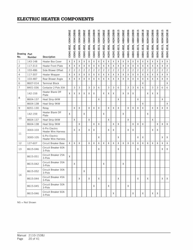
Manual 2110-1538JPage 20 of 41
DrawingNo.
PartNumber Description I3
0H
1-B
0Z,
I3
0H
1D
B0
Z
I30
H1
-B0
6,
I30
H1
DB
06
I30
H1
-B0
9,
I30
H1
DB
09
I36
H1
-B0
Z, I
36
H1
DB
0Z
I36
H1
-B0
6,
I36
H1
DB
06
I36
H1
-B0
9,
I36
H1
DB
09
I36
H1
-B1
5,
I36
H1
DB
15
I42
H1
-B0
Z, I
42
H1
DB
0Z
I42
H1
-B0
6,
I42
H1
DB
06
I42
H1
-B0
9,
I42
H1
DB
09
I42
H1
-B1
5,
I42
H1
DB
15
I48
H1
-B0
Z, I
48
H1
DB
0Z
I48
H1
-B1
5,
I48
H1
DB
15
I48
H1
-B1
8,
I48
H1
DB
18
I60
H1
-B0
Z, I
60
H1
DB
0Z
I60
H1
-B0
6,
I60
H1
DB
06
I60
H1
-B0
9,
I60
H1
DB
09
I60
H1
-B1
5,
I60
H1
DB
15
I60
H1
-B1
8,
I60
H1
DB
18
I48
H1
-B0
6,
I48
H1
DB
06
I48
H1
-B0
9,
I48
H1
DB
09
1 143-148 Heater Box Cover X X X X X X X X X X X X X X X X X X X X X
2 117-313 Heater Front Plate X X X X X X X X X X X X X X X X X X X X X
3 103-486 Side Blower Offset 2 2 2 2 2 2 2 2 2 2 2 2 2 2 2 2 2 2 2 2 2
4 117-307 Heater Wrapper X X X X X X X X X X X X X X X X X X X X X
5 103-487 Rear Blower Angle X X X X X X X X X X X X X X X X X X X X X
6 8607-014 Terminal Block X X
7 8401-036 Contactor 2-Pole 30A 3 3 3 3 6 3 3 6 3 3 6 6 3 3 6 6
8
142-159Heater Blank Off Plate
X X X X X X X X X X X X X X X
8604-137 Heat Strip 6KW X X X X
8604-138 Heat Strip 9KW X X
9 8201-130 Relay X X X X X X X X X X X X X X X X
10
142-159Heater Blank Off Plate
X X X X X
8604-137 Heat Strip 6KW X X X X X
8604-138 Heat Strip 9KW X X X X X X X X X X X
113003-103
6-Pin Electric Heater Wire Harness
X X X X X X X X X X
3000-1056-Pin Electric Heater Wire Harness
X X X X X X
12 127-607 Circuit Breaker Base X X X X X X X X X X X X X X X X X X X X
13 8615-046Circuit Breaker 60A 3-Pole
X X X X X
14
8615-051Circuit Breaker 25A 3-Pole
X
8615-042Circuit Breaker 35A 3-Pole
X X X
8615-052Circuit Breaker 30A 3-Pole
X
8615-044Circuit Breaker 45A 3-Pole
X X X X X X X X
8615-045Circuit Breaker 50A 3-Pole
X X X
8615-046Circuit Breaker 60A 3-Pole
X X X X X
ELECTRIC HEATER COMPONENTS
NS = Not Shown

Manual 2110-1538J Page 21 of 41
DrawingNo.
PartNumber Description I3
0H
1-C
0Z,
I3
0H
1D
C0
Z
I30
H1
-C0
6,
I30
H1
DC
06
I30
H1
-C0
9,
I30
H1
DC
09
I36
H1
-C0
Z, I
36
H1
DC
0Z
I36
H1
-C0
6,
I36
H1
DC
06
I36
H1
-C0
9,
I36
H1
DC
09
I36
H1
-C1
5,
I36
H1
DC
15
I42
H1
-C0
Z, I
42
H1
DC
0Z
I42
H1
-C0
6,
I42
H1
DC
06
I42
H1
-C0
9,
I42
H1
DC
09
I42
H1
-C1
5,
I42
H1
DC
15
I48
H1
-C0
Z, I
48
H1
DC
0Z
I48
H1
-C1
5,
I48
H1
DC
15
I48
H1
-C1
8,
I48
H1
DC
18
I60
H1
-C0
Z, I
60
H1
DC
0Z
I60
H1
-C0
6,
I60
H1
DC
06
I60
H1
-C0
9,
I60
H1
DC
09
I60
H1
-C1
5,
I60
H1
DC
15
I48
H1
-C0
6,
I48
H1
DC
06
I48
H1
-C0
9,
I48
H1
DC
09
I60
H1
-C1
8,
I60
H1
DC
18
I36
H1
DC
15
NP
D1
14
1 143-148 Heater Box Cover X X X X X X X X X X X X X X X X X X X X X X
2 117-313 Heater Front Plate X X X X X X X X X X X X X X X X X X X X X X
3 103-486 Side Blower Offset 2 2 2 2 2 2 2 2 2 2 2 2 2 2 2 2 2 2 2 2 2 2
4 117-307 Heater Wrapper X X X X X X X X X X X X X X X X X X X X X X
5 103-487 Rear Blower Angle X X X X X X X X X X X X X X X X X X X X X X
6 8607-014 Terminal Block X X X X X
7 8401-036 Contactor 2-Pole 30A 2 2 2 2 6 6 2 2 6 2 2 6 4 2 2 6 4
8
142-159Heater Blank Off Plate
X X X X X X X X X X X X X X X
8604-139 Heat Strip 6KW X X X X X
8604-140 Heat Strip 9KW X X
9 8201-130 Relay X X X X X X X X X X X X X X X X X
10
142-159Heater Blank Off Plate
X X X X X
8604-139 Heat Strip 6KW X X X X X
8604-140 Heat Strip 9KW X X X X X X X X X X X X
113003-099
6-Pin Electric Heater Wire Harness
X X X X X X X X X X
3003-1086-Pin Electric Heater Wire Harness
X X X X X X X
12 127-418 Disconnect Base X X X X X X X X X X X X X X X X X X X X X X
15
15
8615-095
8615-077
Toggle Disconnect 40A 460VCircuit Breaker, 30A, 3-Pole, 460V
X X X X X X X
X
X X X X X X X X X X X X X X
NS 8615-069Toggle Disconnect Cover Plate
X X X X X X X X X X X X X X X X X X X X X
ELECTRIC HEATER COMPONENTS
NS = Not Shown

Manual 2110-1538JPage 22 of 41
SEXP-623
4
6
5
1
10
5
7
9
3
8
2
VENT BOX (ONLY) COMPONENTS
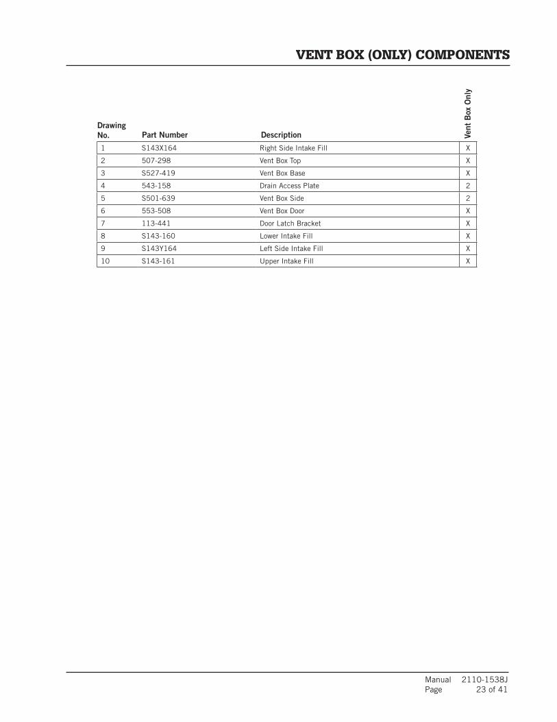
Manual 2110-1538J Page 23 of 41
DrawingNo. Part Number Description Ve
nt B
ox O
nly
1 S143X164 Right Side Intake Fill X
2 507-298 Vent Box Top X
3 S527-419 Vent Box Base X
4 543-158 Drain Access Plate 2
5 S501-639 Vent Box Side 2
6 553-508 Vent Box Door X
7 113-441 Door Latch Bracket X
8 S143-160 Lower Intake Fill X
9 S143Y164 Left Side Intake Fill X
10 S143-161 Upper Intake Fill X
VENT BOX (ONLY) COMPONENTS

Manual 2110-1538JPage 24 of 41
4
3
5
1
2
11
SEXP-622
17
1516
10
1415
16
17
19
13
21
18
12
9
11
8
8
7
6
20
18
CRV COMPONENTS
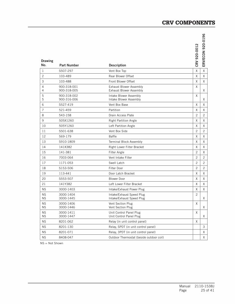
Manual 2110-1538J Page 25 of 41
DrawingNo. Part Number Description C
RV
92
0-0
01
2
ER
V/E
CO
N 9
20
-01
96
1 S507-297 Vent Box Top X X
2 103-489 Rear Blower Offset X X
3 103-488 Front Blower Offset X X
44
900-318-001900-318-005
Exhaust Blower AssemblyExhaust Blower Assembly
XX
55
900-318-002900-316-006
Intake Blower AssemblyIntake Blower Assembly
XX
6 S527-419 Vent Box Base X X
7 521-459 Partition X X
8 543-158 Drain Access Plate 2 2
9 505X1260 Right Partition Angle X X
10 505Y1260 Left Partition Angle X X
11 S501-638 Vent Box Side 2 2
12 569-179 Baffle X X
13 S910-1809 Terminal Block Assembly X X
14 141X382 Right Lower Filter Bracket X X
15 141-381 Filter Angle 2 X
16 7003-064 Vent Intake Filter 2 2
17 1171-053 Swell Latch 2 2
18 S153-506 Filter Door 2 2
19 113-441 Door Latch Bracket X X
20 S553-507 Blower Door X X
21 141Y382 Left Lower Filter Bracket X X
NS 3000-1403 Intake/Exhaust Power Plug X X
NSNS
3000-14043000-1445
Intake/Exhaust Speed PlugIntake/Exhaust Speed Plug
2X
NSNS
3000-14063000-1446
Vent Section PlugVent Section Plug
XX
NSNS
3000-14113000-1447
Unit Control Panel PlugUnit Control Panel Plug
XX
NS 8201-062 Relay (in unit control panel) X
NS 8201-130 Relay, SPDT (in unit control panel) 3
NS 8201-071 Relay, 3PDT (in unit control panel) X
NS 8408-047 Outdoor Thermostat (beside outdoor coil) X
CRV COMPONENTS
NS = Not Shown
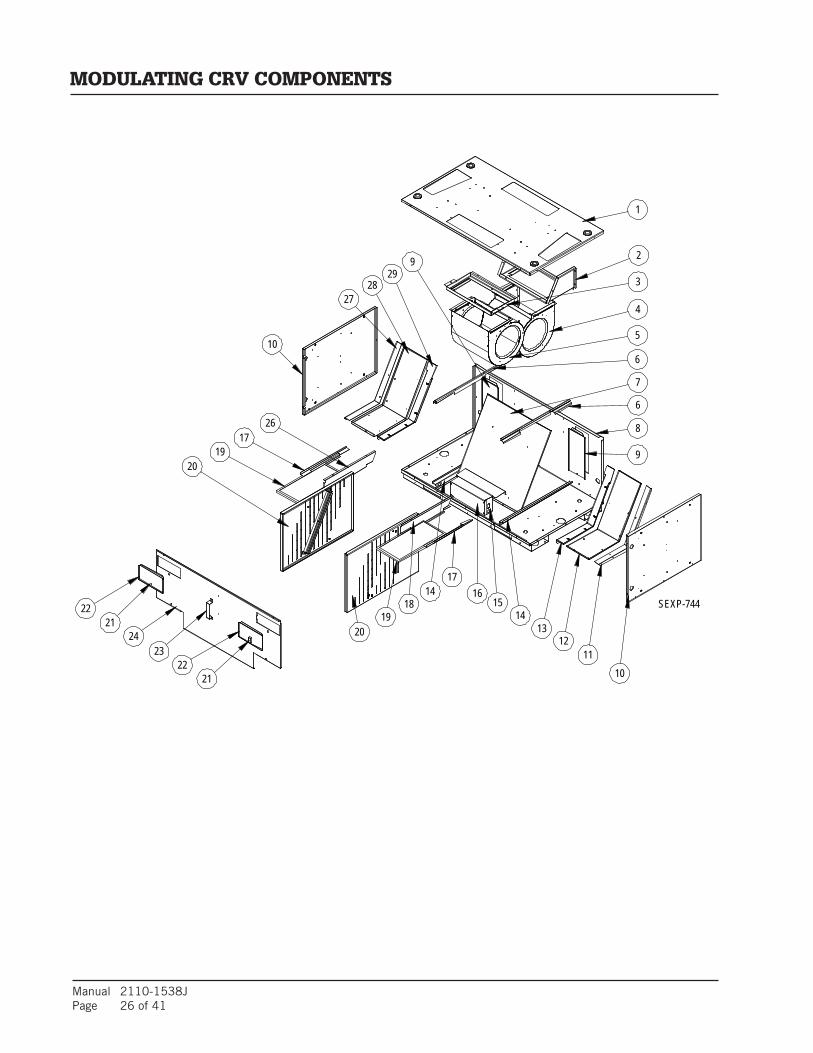
Manual 2110-1538JPage 26 of 41
18
5
SEXP-744
1
2
4
3
6
6
8
9
1312
1110
1415
16
7
19
17
2024
2223
29
21
2122
1917
26
20
27
10
14
28
9
MODULATING CRV COMPONENTS

Manual 2110-1538J Page 27 of 41
DrawingNo. Part Number Description M
odul
atin
g C
RV
1 S507-297 Vent Box Top X
2 103-489 Rear Blower Offset X
3 103-488 Front Blower Offset X
4 900-319-003 Exhaust Blower Assembly X
5 900-319-004 Intake Blower Assembly X
6 141-379 Cassette Upper Rail 2
7 521-457 Partition X
8 S527-419 Vent Box Base X
9 543-158 Drain Access Plate 2
10 S501-638 Vent Box Side 2
11 505X1260 Right Partition Angle X
12 521-464 Right Side Partition X
13 S105X1258 Right Cassette Seal Angle X
14 141-380 Cassette Lower Rail 2
15 Control Panel See Control Panel section x
16 153-511 Control Panel Cover X
17 141-381 Filter Angle 2
18 141X382 Right Lower Filter Bracket X
19 7003-064 Vent Intake Filter 2
20 139-332 Restrictor Plate 2
21 1171-053 Swell Latch 2
22 S153-506 Filter Door 2
23 113-441 Door Latch Bracket X
24 S553-505 Cassette Door X
26 141Y382 Left Lower Filter Bracket X
27 105Y1260 Left Partition Angle X
28 521-465 Left Side Partition X
29 S105Y1258 Left Cassette Seal Angle X
MODULATING CRV COMPONENTS

Manual 2110-1538JPage 28 of 41
9
10 5
6
SEXP-745 A
7
3
11
7
1
MODULATING CRV CONTROL PANEL COMPONENTS
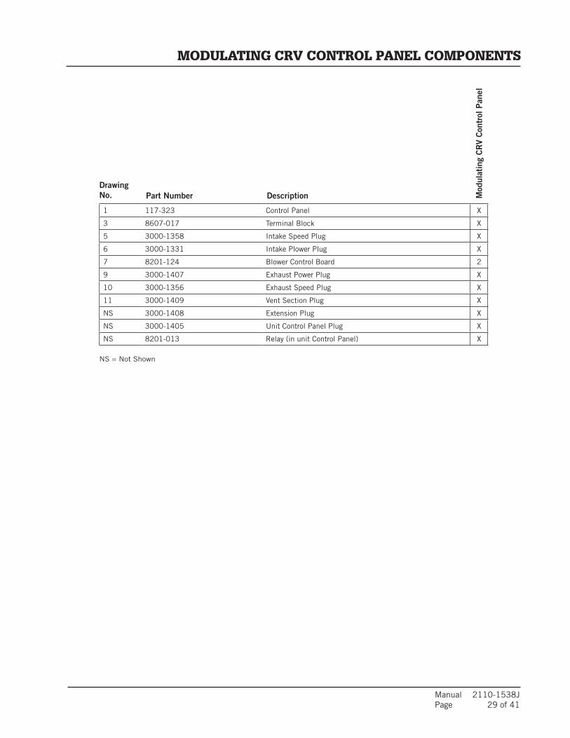
Manual 2110-1538J Page 29 of 41
DrawingNo. Part Number Description M
odul
atin
g C
RV
Con
trol
Pan
el
1 117-323 Control Panel X
3 8607-017 Terminal Block X
5 3000-1358 Intake Speed Plug X
6 3000-1331 Intake Plower Plug X
7 8201-124 Blower Control Board 2
9 3000-1407 Exhaust Power Plug X
10 3000-1356 Exhaust Speed Plug X
11 3000-1409 Vent Section Plug X
NS 3000-1408 Extension Plug X
NS 3000-1405 Unit Control Panel Plug X
NS 8201-013 Relay (in unit Control Panel) X
MODULATING CRV CONTROL PANEL COMPONENTS
NS = Not Shown
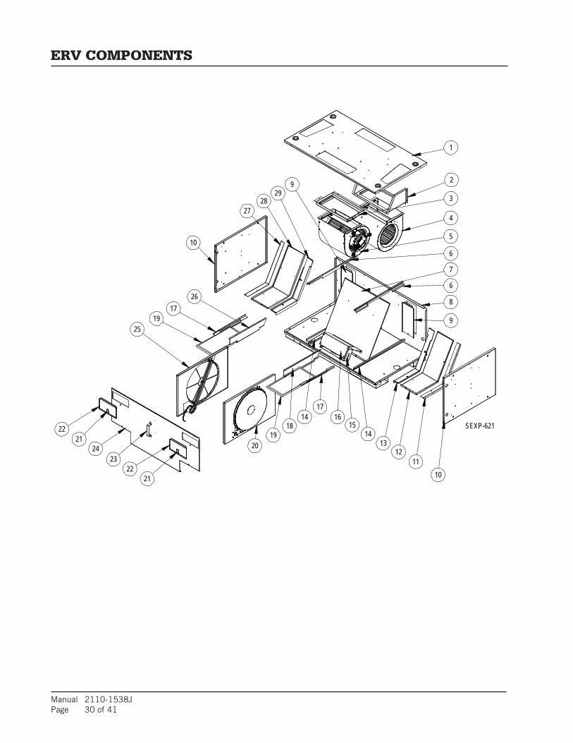
Manual 2110-1538JPage 30 of 41
28
4
29
1
2
273
7
6
5
SEXP-621
9
14
10
18
2617
1925
22
24
17
22
2019
1615
1112
1421
21 10
23
13
9
8
6
ERV COMPONENTS

Manual 2110-1538J Page 31 of 41
DrawingNo. Part Number Description E
RV
1 S507-297 Vent Box Top X
2 103-489 Rear Blower Offset X
3 103-488 Front Blower Offset X
4 900-319-001 Exhaust Blower Assembly X
5 900-319-002 Intake Blower Assembly X
6 141-379 Cassette Upper Rail 2
7 521-457 Partition X
8 S527-419 Vent Box Base X
9 543-158 Drain Access Plate 2
10 S501-638 Vent Box Side 2
11 505X1260 Right Partition Angle X
12 521-464 Right Side Partition X
13 S105X1258 Right Cassette Seal Angle X
14 141-380 Cassette Lower Rail 2
15 Control Panel See Control Panel section x
16 153-511 Control Panel Cover X
17 141-381 Filter Angle 2
18 141X382 Right Lower Filter Bracket X
19 7003-064 Vent Intake Filter 2
20 5070-055Right Cassette Assembly - CompleteSee cassette section for individual parts
X
21 1171-053 Swell Latch 2
22 S153-506 Filter Door 2
23 113-441 Door Latch Bracket X
24 S553-505 Cassette Door X
25 5070-056Left Cassette Assembly - CompleteSee cassette section for individual parts
X
26 141Y382 Left Lower Filter Bracket X
27 105Y1260 Left Partition Angle X
28 521-465 Left Side Partition X
29 S105Y1258 Left Cassette Seal Angle X
ERV COMPONENTS

Manual 2110-1538JPage 32 of 41
510
96
SEXP-943
4
114
7 7
2 3 21
ERV CONTROL PANEL COMPONENTS

Manual 2110-1538J Page 33 of 41
DrawingNo. Part Number Description E
RV
Con
trol
Pan
el
1 117-323 Control Panel X
2 8552-073 3MFD 250V Capacitor 2
3 8607-017 Terminal Block X
4 3000-1648 Cassette Motor Plug 2
5 3000-1358 Intake Speed Plug X
6 3000-1331 Intake Plower Plug X
7 8201-124 Blower Control Board 2
9 3000-1407 Exhaust Power Plug X
10 3000-1356 Exhaust Speed Plug X
11 3000-1409 Vent Section Plug X
NS 3000-1408 Extension Plug X
NS 3000-1405 Unit Control Panel Plug X
NS 8201-013 Relay (in unit Control Panel) X
ERV CONTROL PANEL COMPONENTS
NS = Not Shown
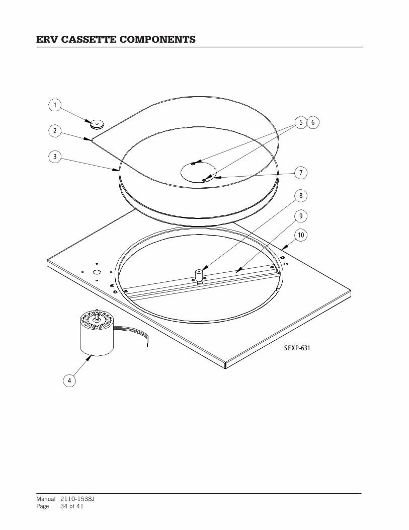
Manual 2110-1538JPage 34 of 41
2
SEXP-631
1
6
10
4
3
8
9
5
7
ERV CASSETTE COMPONENTS

Manual 2110-1538J Page 35 of 41
DrawingNo. Part Number Description 5
07
0-0
55
Rig
ht C
asse
tte
50
70
-05
6 L
eft
Cas
sett
e
1 5501-018 Pulley X X
2 5070-054 Drive Belt X X
3 5070-043 Cassette Wheel X X
4 8101-021 Motor X X
5 1012-164 Machine Screw 2 2
6 8611-111 Nylon Spacer 2 2
7 142-104 Hub Cover X X
8 1912-012 Wheel Shaft X X
9 105-1259 Cassette Wheel Angle X X
10 539X275 Right Hand Cassette Plate X
10 539Y275 Left Hand Cassette Plate X
NS 8620-204 ERV Bearing, Shaft & Hardware Kit X X
NS 8620-205 ERV Shaft & Hardware Kit X X
ERV CASSETTE COMPONENTS
NS = Not Shown

Manual 2110-1538JPage 36 of 41
4
SEXP-628
5
3
12
6
CRV/ERV BLOWER COMPONENTS
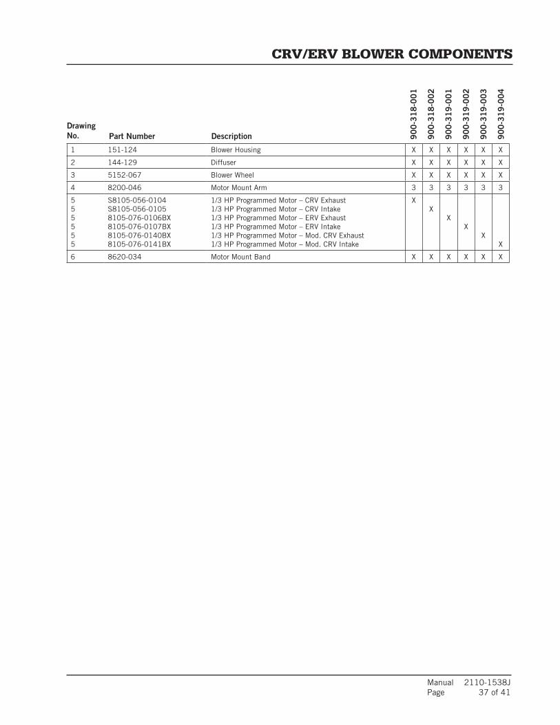
Manual 2110-1538J Page 37 of 41
DrawingNo. Part Number Description 9
00
-31
8-0
01
90
0-3
18
-00
2
90
0-3
19
-00
1
90
0-3
19
-00
2
90
0-3
19
-00
3
90
0-3
19
-00
4
1 151-124 Blower Housing X X X X X X
2 144-129 Diffuser X X X X X X
3 5152-067 Blower Wheel X X X X X X
4 8200-046 Motor Mount Arm 3 3 3 3 3 3
555555
S8105-056-0104S8105-056-01058105-076-0106BX8105-076-0107BX8105-076-0140BX8105-076-0141BX
1/3 HP Programmed Motor – CRV Exhaust1/3 HP Programmed Motor – CRV Intake1/3 HP Programmed Motor – ERV Exhaust1/3 HP Programmed Motor – ERV Intake1/3 HP Programmed Motor – Mod. CRV Exhaust1/3 HP Programmed Motor – Mod. CRV Intake
XX
XX
XX
6 8620-034 Motor Mount Band X X X X X X
CRV/ERV BLOWER COMPONENTS

Manual 2110-1538JPage 38 of 41
8
6
1
2
3
4
5
7
9
SEXP-632
SLEEVE COMPONENTS

Manual 2110-1538J Page 39 of 41
DrawingNo. Part Number Description IW
S-A
IWS
-B
IWS
-C
1
S111-188-8 4½" Deep
Outer Sleeve Side
2
S111-195-8 7" Deep 2
S111-202-8 12" Deep 2
2
S111-187-8 4½" Deep
Outer Sleeve End
2
S111-194-8 7" Deep 2
S111-201-8 12" Deep 2
3
111-189-8 4½" Deep
Inner Fan Sleeve Side
2
111-196-8 7" Deep 2
111-203-8 12" Deep 2
4
111-186-8 3½" Deep
Inner Sleeve Side
2
111-193-8 6" Deep 2
111-200-8 11" Deep 2
5
111-185-8 3½" Deep
Inner Sleeve End
2
111-192-8 6" Deep 2
111-199-8 11" Deep 2
6 105-1257-8 Grille Support Angle 2 2 2
7
111-184-8 5½" Deep
Outer Sleeve Side
2
111-191-8 8" Deep 2
111-198-8 13" Deep 2
8
111-183-8 5½" Deep
Outer Sleeve End
2
111-190-8 8" Deep 2
111-197-8 13" Deep 2
9
ILG-10 Outdoor Louver Grille - Clear anodized X X X
ILG-20 Outdoor Louver Grille - Medium Bronze X X X
ILG-30 Outdoor Louver Grille - Dark Bronze X X X
SLEEVE COMPONENTS

Manual 2110-1538JPage 40 of 41
4
5
6
SEXP-633
3
17
25
RISER PLATFORM COMPONENTS
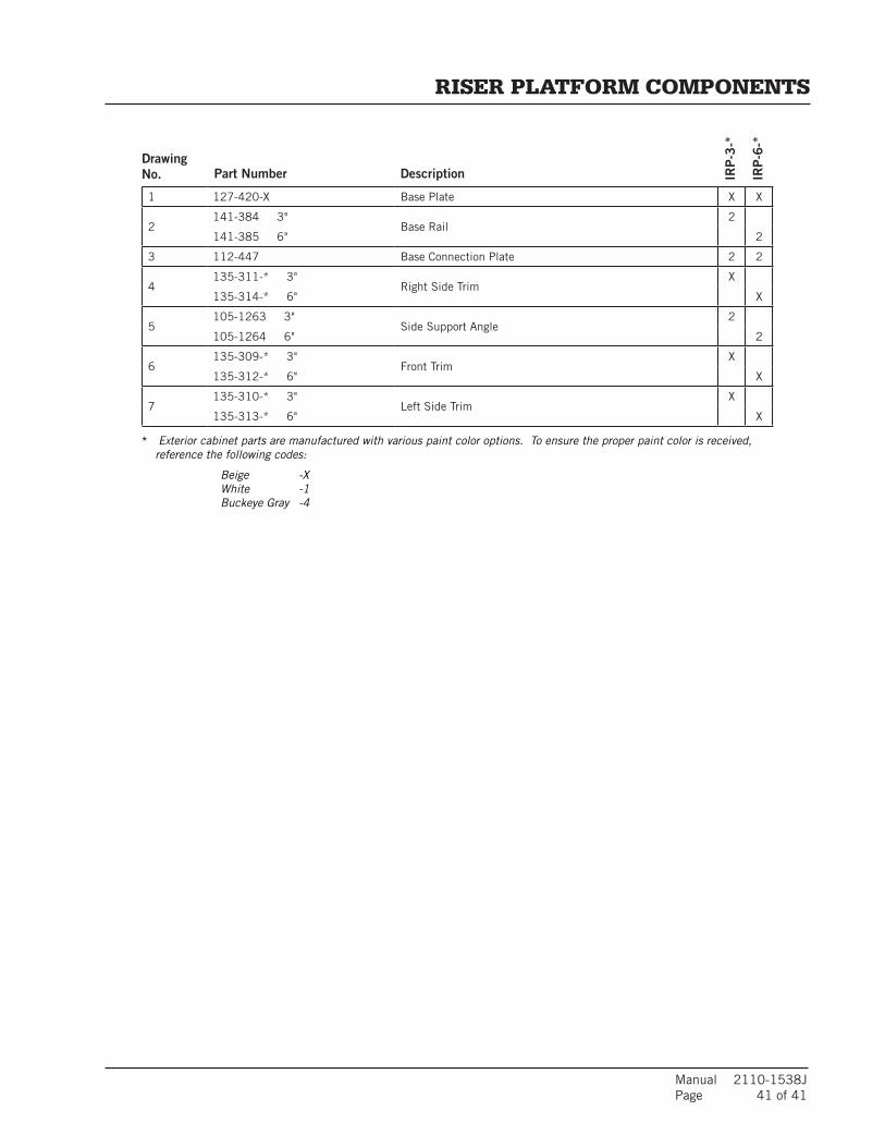
Manual 2110-1538J Page 41 of 41
DrawingNo. Part Number Description IR
P-3
-*
IRP
-6-*
1 127-420-X Base Plate X X
2141-384 3"
Base Rail2
141-385 6" 2
3 112-447 Base Connection Plate 2 2
4135-311-* 3"
Right Side TrimX
135-314-* 6" X
5105-1263 3"
Side Support Angle2
105-1264 6" 2
6135-309-* 3"
Front TrimX
135-312-* 6" X
7135-310-* 3"
Left Side TrimX
135-313-* 6" X
RISER PLATFORM COMPONENTS
* Exterior cabinet parts are manufactured with various paint color options. To ensure the proper paint color is received, reference the following codes:
Beige -X White -1 Buckeye Gray -4

BARD MANUFACTURING CO., INC. — BRYAN, OHIO 43506 Dependable quality equipment . . . since 1914
Limited Warranty
Limited Warranty To Original Purchaser: Bard Manufacturing Company, Inc. Bryan, Ohio 43506 warrants to you, the original purchaser, that your Bard product will be free from defects in materials and workmanship when used under normal conditions from the installation date through the time periods outlined in the “Duration of Warranty” section (see reverse side).
Proof Of Purchase: You must be able to show us the date on which you purchased your product when you make a claim under this warranty. Your owner’s registration card filed online at www.wallmountwarranty.com or your contractor’s invoice, bill of sale, or similar document is sufficient at time of warranty claim. If you can not show us the actual date of purchase, the time periods in this warranty will start on the date that we shipped your Bard product from our factory.
What This Warranty Does Not Cover: (Also see Duration of Warranty on reverse side.) This warranty does not cover defects or damage caused by: 1. Alterations not approved by us; improper installation (including over or under sizing), improper repairs, or servicing; or improper parts and accessories not supplied by us. 2. Misuse or failure to follow installation and operating instructions (including failure to perform preventative maintenance) or limitations on the rating plate. This includes failure to use low ambient controls on all applications requiring compressor operation in cooling mode below 60F outdoor ambient. 3. Any corrosion from operation in a corrosive atmosphere (examples: acids, halogenated hydrocarbons or environmental conditions). 4. Parts that must be replaced periodically (such as filters, oil nozzles, mist eliminators, ERV belts, pile seals, etc.). 5. Improper fuel or electrical supply (such as low voltage, voltage transients, power interruption, and units on generators with no brownout protection). 6. Accidents or other events beyond our reasonable control (such as storm, fire, or transportation damage). 7. Defects that happen after (a) Anyone has tampered with the product. (b) The product has been improperly serviced according to accepted trade practices; (c) The product has been moved from its original place of installation; or, (d) The product has been damaged by an event beyond Bard’s control (See also No. 5 above). 8. Consequential damages (such as increased living expenses while the product is being repaired). Some states do not allow the exclusion or limitation of incidental or consequential damages, so the above limitation or exclusion may not apply to you. 9. This warranty has certain limitations for units installed on over-the-road trucks, vans and trailers. (See reverse side.) 10. Cost of service call at installation site to diagnose causes of trouble, labor to replace defective component or transportation costs for replacement parts.11. This Limited Warranty does not apply to products installed or operated outside of the US, Puerto Rico, US Virgin Islands, Guam, Canda and Mexico. Units operated in coastal areas where the operating environment is exposed to airborne saline particles (typically 5 miles from coast line) must have corrosion protection or warrenty claims will be declined on corrosion-based cabinet and part failures.12. Bard does not endorse, approve or certify any online sales of its products through auction websites, online retailers, liquidators or any other method of online sales direct to consumers. Bard will not honor the factory warranty of any Bard equipment purchased over the Internet. Your Responsibilities: You are responsible for - 1. Preventative maintenance of the product (such as cleaning and replacement of filters, nozzles and other consumable parts). 2. Insuring that the instruction manual is followed for care and use of your product. 3. Insuring that your product is installed by a competent, qualified contractor, following all local and national codes, and industry standards.
What We Will Do About A Defect: We will either repair or replace the defective part only. Replacement parts may be reconditioned parts. The warranty for the repaired or replacedpart will last only for the remainder of the warranty period for the original part. For Heat Exchangers that are no longer available, we will give you credit equal to the then current retail price of an equivalent Heat Exchanger.
Defective parts and a properly completed Bard parts warranty form must be returned to a Bard distributor for submitting to Bard to be eligible for a warranty credit or replacement. Credits are issued to the Bard distributor.
We will not pay or be responsible for labor or defective/replacement part transportation costs or delays in repairing or failures to complete repairs caused by events beyond our reasonable control.
What You Must Do 1. Tell your heating and air conditioning contractor as soon as you discover a problem and have the contractor make repairs. 2. Pay for all transportation, related service labor, diagnostic charges, refrigerant, refrigerant recovery and related items.
Service If your product requires service, you should contact the contractor who installed it or the contractor that has been providing the product’s preventative maintenance and repair service. You may find the installing contractor’s name on the product or in your Owner’s packet. If you do not know who that is, you should contact a competent, qualified contractor to make the repairs. If in doubt, you should contact the nearest distributor that handles Bard products (www.bardhvac.com). Please note that contractors and distributors that handle Bard products are independent contractors and distributors, and therefore, are not under the direction of Bard Manufacturing Company, Inc.
Only Warranty This is the only warranty that we make. There are no other express warranties. All implied warranties are limited in duration to the duration of the applicable written warranty made above. Some states do not allow limitations on how long an implied warranty lasts, so the above limitation or exclusion may not apply to you. Other Rights This warranty gives you specific legal rights and you may have other rights which vary from state to state.
For units applied within the United States, Puerto Rico, US Virgin Islands, Guam, Canada and Mexico
Form No. 7960-420 Issued: 12/04/19Supersedes: 08/22/19
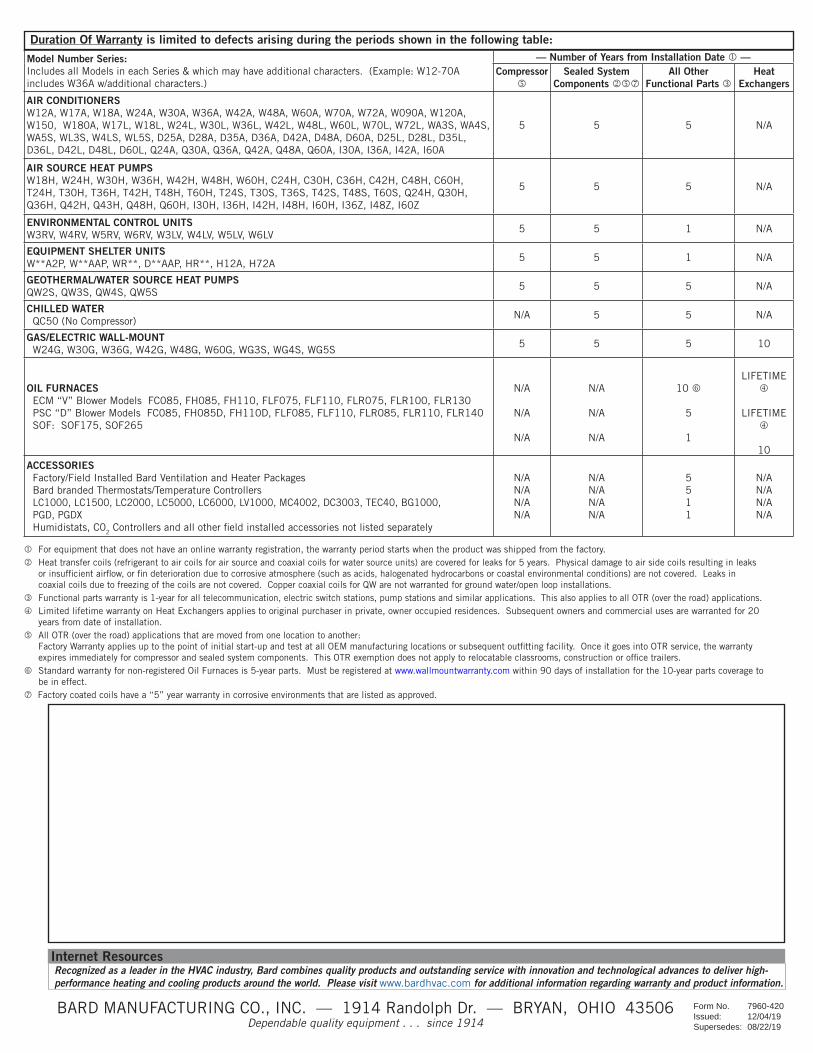
Recognized as a leader in the HVAC industry, Bard combines quality products and outstanding service with innovation and technological advances to deliver high- performance heating and cooling products around the world. Please visit www.bardhvac.com for additional information regarding warranty and product information.
Duration Of Warranty is limited to defects arising during the periods shown in the following table:
For equipment that does not have an online warranty registration, the warranty period starts when the product was shipped from the factory. Heat transfer coils (refrigerant to air coils for air source and coaxial coils for water source units) are covered for leaks for 5 years. Physical damage to air side coils resulting in leaks or insufficient airflow, or fin deterioration due to corrosive atmosphere (such as acids, halogenated hydrocarbons or coastal environmental conditions) are not covered. Leaks in coaxial coils due to freezing of the coils are not covered. Copper coaxial coils for QW are not warranted for ground water/open loop installations. Functional parts warranty is 1-year for all telecommunication, electric switch stations, pump stations and similar applications. This also applies to all OTR (over the road) applications. Limited lifetime warranty on Heat Exchangers applies to original purchaser in private, owner occupied residences. Subsequent owners and commercial uses are warranted for 20 years from date of installation. All OTR (over the road) applications that are moved from one location to another: Factory Warranty applies up to the point of initial start-up and test at all OEM manufacturing locations or subsequent outfitting facility. Once it goes into OTR service, the warranty expires immediately for compressor and sealed system components. This OTR exemption does not apply to relocatable classrooms, construction or office trailers. Standard warranty for non-registered Oil Furnaces is 5-year parts. Must be registered at www.wallmountwarranty.com within 90 days of installation for the 10-year parts coverage to be in effect. Factory coated coils have a “5” year warranty in corrosive environments that are listed as approved.
Model Number Series:Includes all Models in each Series & which may have additional characters. (Example: W12-70A includes W36A w/additional characters.)
— Number of Years from Installation Date —Compressor
Sealed System
Components All Other
Functional Parts Heat
Exchangers
AIR CONDITIONERSW12A, W17A, W18A, W24A, W30A, W36A, W42A, W48A, W60A, W70A, W72A, W090A, W120A, W150, W180A, W17L, W18L, W24L, W30L, W36L, W42L, W48L, W60L, W70L, W72L, WA3S, WA4S, WA5S, WL3S, W4LS, WL5S, D25A, D28A, D35A, D36A, D42A, D48A, D60A, D25L, D28L, D35L, D36L, D42L, D48L, D60L, Q24A, Q30A, Q36A, Q42A, Q48A, Q60A, I30A, I36A, I42A, I60A
5 5 5 N/A
AIR SOURCE HEAT PUMPSW18H, W24H, W30H, W36H, W42H, W48H, W60H, C24H, C30H, C36H, C42H, C48H, C60H, T24H, T30H, T36H, T42H, T48H, T60H, T24S, T30S, T36S, T42S, T48S, T60S, Q24H, Q30H, Q36H, Q42H, Q43H, Q48H, Q60H, I30H, I36H, I42H, I48H, I60H, I36Z, I48Z, I60Z
5 5 5 N/A
ENVIRONMENTAL CONTROL UNITSW3RV, W4RV, W5RV, W6RV, W3LV, W4LV, W5LV, W6LV
5 5 1 N/A
EQUIPMENT SHELTER UNITSW**A2P, W**AAP, WR**, D**AAP, HR**, H12A, H72A
5 5 1 N/A
GEOTHERMAL/WATER SOURCE HEAT PUMPSQW2S, QW3S, QW4S, QW5S
5 5 5 N/A
CHILLED WATERQC50 (No Compressor)
N/A 5 5 N/A
GAS/ELECTRIC WALL-MOUNTW24G, W30G, W36G, W42G, W48G, W60G, WG3S, WG4S, WG5S
5 5 5 10
OIL FURNACESECM “V” Blower Models FC085, FH085, FH110, FLF075, FLF110, FLR075, FLR100, FLR130PSC “D” Blower Models FC085, FH085D, FH110D, FLF085, FLF110, FLR085, FLR110, FLR140SOF: SOF175, SOF265
N/A
N/A
N/A
N/A
N/A
N/A
10
5
1
LIFETIME
LIFETIME
10
ACCESSORIESFactory/Field Installed Bard Ventilation and Heater PackagesBard branded Thermostats/Temperature ControllersLC1000, LC1500, LC2000, LC5000, LC6000, LV1000, MC4002, DC3003, TEC40, BG1000, PGD, PGDXHumidistats, C02 Controllers and all other field installed accessories not listed separately
N/AN/AN/AN/A
N/AN/AN/AN/A
5511
N/AN/AN/AN/A
BARD MANUFACTURING CO., INC. — 1914 Randolph Dr. — BRYAN, OHIO 43506 Dependable quality equipment . . . since 1914
Internet Resources
Form No. 7960-420 Issued: 12/04/19Supersedes: 08/22/19

Literature Assembly
911-0566-2 BOOK 2 OF 2
Contains The Following:
2100-034G Users Guide


Climate Control Solutions
BARDHVAC.COM
Bard Manufacturing Company, Inc. Bryan, Ohio 43506 www.bardhvac.com
Manual: 2100-034GSupersedes: 2100-034F Date: 12-17-20
USER’S APPLICATION GUIDE AND TECHNICAL PRODUCT OVERVIEW
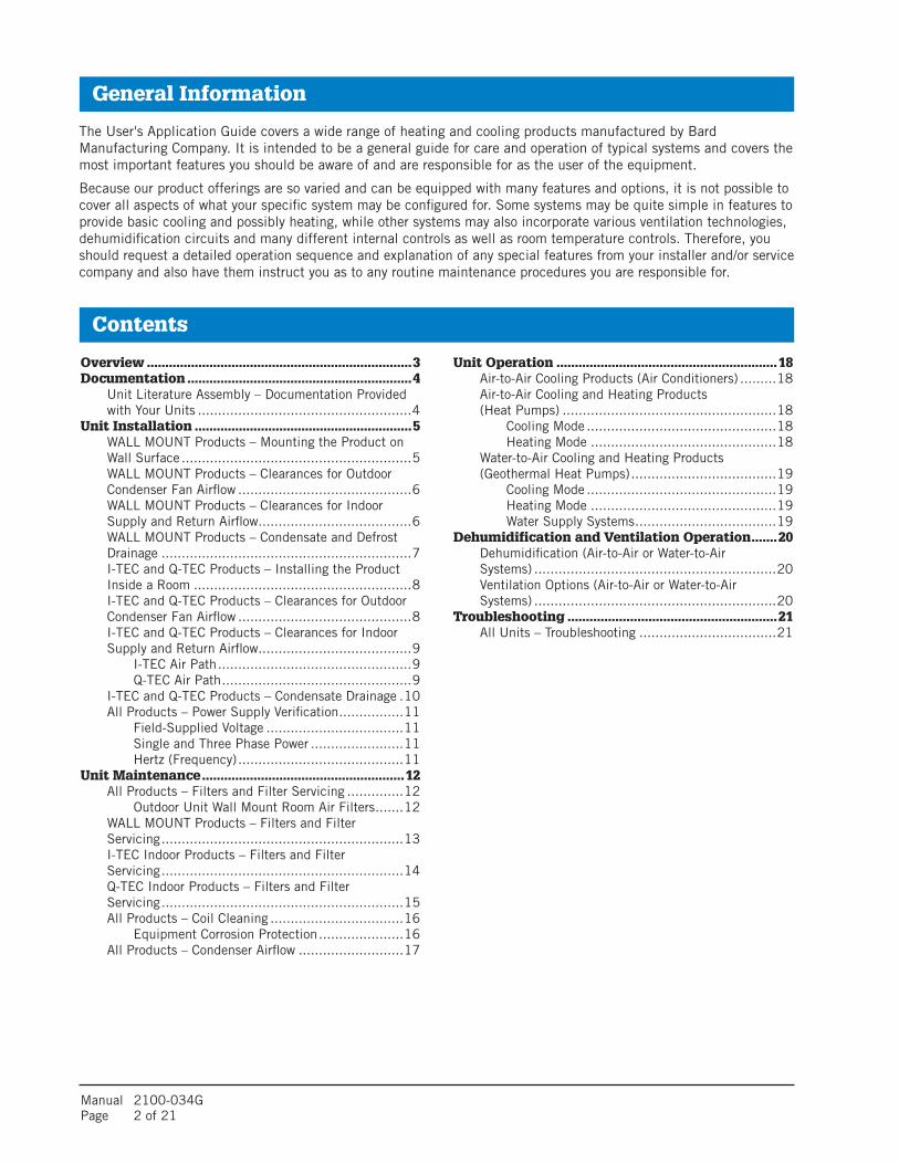
Manual 2100-034G Page 2 of 21
General Information
The User's Application Guide covers a wide range of heating and cooling products manufactured by Bard Manufacturing Company. It is intended to be a general guide for care and operation of typical systems and covers the most important features you should be aware of and are responsible for as the user of the equipment.
Because our product offerings are so varied and can be equipped with many features and options, it is not possible to cover all aspects of what your specific system may be configured for. Some systems may be quite simple in features to provide basic cooling and possibly heating, while other systems may also incorporate various ventilation technologies, dehumidification circuits and many different internal controls as well as room temperature controls. Therefore, you should request a detailed operation sequence and explanation of any special features from your installer and/or service company and also have them instruct you as to any routine maintenance procedures you are responsible for.
Contents
Overview ........................................................................3Documentation .............................................................4 Unit Literature Assembly – Documentation Provided
with Your Units .....................................................4Unit Installation ...........................................................5 WALL MOUNT Products – Mounting the Product on
Wall Surface .........................................................5 WALL MOUNT Products – Clearances for Outdoor
Condenser Fan Airflow ...........................................6 WALL MOUNT Products – Clearances for Indoor
Supply and Return Airflow ......................................6 WALL MOUNT Products – Condensate and Defrost
Drainage ..............................................................7 I-TEC and Q-TEC Products – Installing the Product
Inside a Room ......................................................8 I-TEC and Q-TEC Products – Clearances for Outdoor
Condenser Fan Airflow ...........................................8 I-TEC and Q-TEC Products – Clearances for Indoor
Supply and Return Airflow ......................................9 I-TEC Air Path ................................................9 Q-TEC Air Path ...............................................9 I-TEC and Q-TEC Products – Condensate Drainage .10 All Products – Power Supply Verification ................11 Field-Supplied Voltage ..................................11 Single and Three Phase Power .......................11 Hertz (Frequency) .........................................11Unit Maintenance .......................................................12 All Products – Filters and Filter Servicing ..............12 Outdoor Unit Wall Mount Room Air Filters .......12 WALL MOUNT Products – Filters and Filter
Servicing ............................................................13 I-TEC Indoor Products – Filters and Filter
Servicing ............................................................14 Q-TEC Indoor Products – Filters and Filter
Servicing ............................................................15 All Products – Coil Cleaning .................................16 Equipment Corrosion Protection .....................16 All Products – Condenser Airflow ..........................17
Unit Operation ............................................................18 Air-to-Air Cooling Products (Air Conditioners) .........18 Air-to-Air Cooling and Heating Products
(Heat Pumps) .....................................................18 Cooling Mode ...............................................18 Heating Mode ..............................................18 Water-to-Air Cooling and Heating Products (Geothermal Heat Pumps) ....................................19 Cooling Mode ...............................................19 Heating Mode ..............................................19 Water Supply Systems ...................................19Dehumidification and Ventilation Operation .......20 Dehumidification (Air-to-Air or Water-to-Air
Systems) ............................................................20 Ventilation Options (Air-to-Air or Water-to-Air
Systems) ............................................................20Troubleshooting .........................................................21 All Units – Troubleshooting ..................................21

Manual 2100-034G Page 3 of 21
Overview
The User's Application Guide and Technical Product Overview covers the following products:
WALL MOUNTAir Conditioners and Heat Pumps
I-TEC®
Air Conditioners and Heat Pumps
Q-TECTM
Air Conditioners and Heat Pumps
The User's Application Guide and Technical Product Overview covers the following topics:
• Documentation provided by Bard for proper use of your new product. • Unit installation guidelines.• Routine unit maintenance.• Unit operation.• Unit troubleshooting.
Please use this guide as a general overview regarding unit application, maintenance and troubleshooting. Refer to product installation instructions and supplemental documentation provided with the unit or go to www.bardhvac.com for detailed individual product information.
Overview

Manual 2100-034G Page 4 of 21
Documentation
There are two sources of valuable information for your new Bard product:
• Documentation provided with your unit, normally located inside the unit control panel during shipping. This information should be saved once the unit is installed for future maintenance reference or to answer questions about equipment after installation.
• Documentation provided on the internet at www.bardhvac.com. This may be accessed from a desktop computer at the office, a laptop or an internet-capable cell phone at the worksite. Up-to-date documentation is available, along with specification sheets and other valuable resources regarding your new Bard product.
Unit Literature Assembly – Documentation Provided with Your UnitBard products are shipped with documentation that when used by a technician with cooling and heating knowledge, can ensure that your product is installed safely, performs optimally and achieves the longest life cycle possible.
Shipped literature includes the following:
• User Manual (this document)• Installation Instructions• Replacement Parts Manual• Wiring Diagrams• Warranty Information
Documentation

Manual 2100-034G Page 5 of 21Unit Installation – Wall Mount
Unit Installation
Installation plays a key part in unit functionality, performance and safety. Product securing and placement, duct design and supply/return location, electrical routing and condensate and defrost drainage all play key roles in making sure a unit will perform per the design specifications.
WALL MOUNT Products – Mounting the Product on a Wall Surface
Outdoor products are normally mounted to an exterior wall surface, including brick, cement block, metal or wood construction. These products are labeled as “WALL MOUNT” units. Before installation begins, the wall surface should be inspected by a construction professional to ensure it will support the weight of the unit and accessory items. Approximate weights are available from the product specification sheet, and a safety factor should be designed into the installation. Typical fasteners to attach the unit to the wall using the integrated mounting flanges on both sides of the unit include tap cons, bolts, studs and other fastening devices. The selection of the fasteners to be used needs to be reviewed by a construction professional and decided upon based on the wall construction and fastener strength required. It is important to follow all guidelines and procedures covered in the installation instructions manual provided for the product.
Built-In Mounting Flange Detail:Outdoor WALL MOUNT products include a mounting flange that is part of the cabinet construction. Ø.375" holes are provided for unit mounting unless specified otherwise in installation instructions.
Specification Sheets:Unit specification sheets provided at www.bardhvac.com include basic unit weights and dimensions (see example below). Ventilation options and other accessories must be added into the total weight of the unit.
Specification Sheet Example

Manual 2100-034G Page 6 of 21 Unit Installation – Wall Mount
WALL MOUNT Products – Clearances for Outdoor Condenser Fan AirflowUnit placement and avoidance of obstructions outside the structure are very critical to unit performance. Avoid installing the unit in areas that will obstruct outdoor condenser fan airflow or create “pockets” of heated air being exhausted from the condenser coil. Solid construction fences should not be placed directly in front of the unit without provisions for condenser airflow. Solid exterior walls need to be spaced as far away from units as possible to avoid pockets of heated air causing condenser air recirculation.
Solid barriers located too close to the face or side surfaces (condenser fan inlet and outlet) of the WALL MOUNT can both impede airflow and force heated air to short circuit (be returned) from the condenser outlet to the condenser inlet. Either condition will effectively raise the condensing temperature and pressure reducing cooling capacity and efficiency. In extreme cases, the unit may fail to operate due to high refrigerant pressures inside the unit, and compressor and/or fan motor failure may occur. Clearances given in installation instructions ensure components can be serviced and maintenance can be performed when needed.
National and local electrical codes must be reviewed before unit installation.
Always use common sense when installing products, follow unit clearances given in the installation instructions and contact local Bard distributors when additional knowledge is needed regarding unit clearances for proper unit functionality.
WALL MOUNT Products – Clearances for Indoor Supply and Return AirflowThe Bard unit should be placed in an area where the supply (leaving conditioned air) and return (unit air intake) air paths will be unrestricted. Avoid placing objects in the structure within 24" of the return (unit air intake) grille. Avoid placing objects directly in the path of the supply (conditioned) air grille. This will inhibit the “throw” of the supply air throughout the structure and reduce the cooling and/or heating ability of the unit; in extreme cases, this may cause evaporator coil freezing issues. Supply air must be able to freely circulate conditioned air throughout the structure. Adjustment of supply grille deflectors is often necessary to ensure proper room circulation.
Ducted applications should not exceed the rated duct static pressures given in the unit specification sheets. Special requirements for duct construction and distances to combustible materials need to be followed per the installation instructions when electric heating is used.
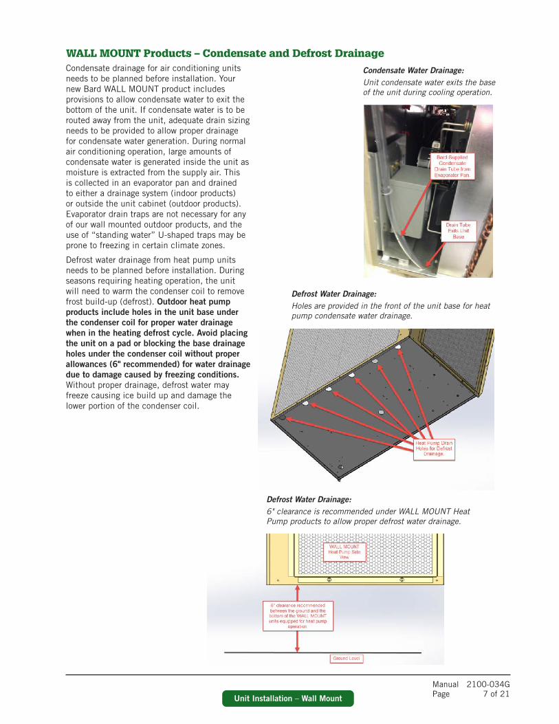
Manual 2100-034G Page 7 of 21Unit Installation – Wall Mount
WALL MOUNT Products – Condensate and Defrost Drainage
Condensate Water Drainage:Unit condensate water exits the base of the unit during cooling operation.
Defrost Water Drainage:Holes are provided in the front of the unit base for heat pump condensate water drainage.
Defrost Water Drainage:6" clearance is recommended under WALL MOUNT Heat Pump products to allow proper defrost water drainage.
Condensate drainage for air conditioning units needs to be planned before installation. Your new Bard WALL MOUNT product includes provisions to allow condensate water to exit the bottom of the unit. If condensate water is to be routed away from the unit, adequate drain sizing needs to be provided to allow proper drainage for condensate water generation. During normal air conditioning operation, large amounts of condensate water is generated inside the unit as moisture is extracted from the supply air. This is collected in an evaporator pan and drained to either a drainage system (indoor products) or outside the unit cabinet (outdoor products). Evaporator drain traps are not necessary for any of our wall mounted outdoor products, and the use of “standing water” U-shaped traps may be prone to freezing in certain climate zones.
Defrost water drainage from heat pump units needs to be planned before installation. During seasons requiring heating operation, the unit will need to warm the condenser coil to remove frost build-up (defrost). Outdoor heat pump products include holes in the unit base under the condenser coil for proper water drainage when in the heating defrost cycle. Avoid placing the unit on a pad or blocking the base drainage holes under the condenser coil without proper allowances (6" recommended) for water drainage due to damage caused by freezing conditions. Without proper drainage, defrost water may freeze causing ice build up and damage the lower portion of the condenser coil.

Manual 2100-034G Page 8 of 21 Unit Installation – I-TEC and Q-TEC
I-TEC and Q-TEC Products – Installing the Product Inside a RoomIndoor products are normally supported by the floor surface and are adjacent to an interior wall surface, including brick, cement block, metal or wood construction. These products are normally labeled as “I-TEC” or “Q-TEC” units. Before installation begins, the floor surface should be inspected by a construction professional to ensure it will support the weight of the unit and accessory items. Approximate weights are available from the product specification sheet, and a safety factor should be designed into the installation.
A sheet metal sleeve is normally installed in the wall allowing vent and condenser fan air to enter and exit the unit. Different sleeve depths are available for installation into various wall depths. Typical fasteners to attach the sleeve to the outside surface of the wall include tap cons and other fastening devices. The I-TEC or Q-TEC unit is then slid up to the wall surface and connected to the sleeve using screws. Trim kits are available to enclose gaps between the wall surface and the unit. A louver grille is used to cover the external wall opening and fasteners used during sleeve installation.
Wall Sleeve:Wall sleeves allow for outdoor air to enter and exit the unit inside the room.
Air Paths:Air paths through the unit allow for cooling operation and fresh air to enter the structure (I-TEC shown).
Louver Installation:Outdoor louvers provide an esthetically pleasing look to the installation and cover the unit opening (I-TEC shown).
I-TEC and Q-TEC Products – Clearances for Outdoor Condenser Fan AirflowSolid barriers located too close to the face of the outdoor louver of the I-TEC or Q-TEC can both impede airflow and force heated air to short circuit (be returned) from the condenser outlet to the condenser inlet. Either condition will effectively raise the condensing temperature and pressure reducing cooling capacity and efficiency. In extreme cases, the unit may fail to operate due to high refrigerant pressures inside the unit, and compressor and/or fan motor failure may occur. It is recommended to allow 15' (457.2 cm) in front of unit louver for proper condenser airflow. Always use common sense when installing products, follow unit clearances given in the installation instructions and contact local Bard distributors when additional knowledge is needed regarding unit clearances for proper unit functionality.
I-TEC
Q-TEC
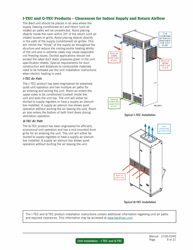
Manual 2100-034G Page 9 of 21Unit Installation – I-TEC and Q-TEC
I-TEC and Q-TEC Products – Clearances for Indoor Supply and Return Airflow
Typical I-TEC Installation
Typical Q-TEC Installation
The Bard unit should be placed in an area where the supply (leaving conditioned air) and return (unit air intake) air paths will be unrestricted. Avoid placing objects inside the room within 24" of the return (unit air intake) louvers or grille. Avoid placing objects directly in the path of the supply (conditioned) air grilles. This will inhibit the “throw” of the supply air throughout the structure and reduce the cooling and/or heating ability of the unit and in extreme cases may cause evaporator coil freezing issues. Ducted applications should not exceed the rated duct static pressures given in the unit specification sheets. Special requirements for duct construction and distances to combustible materials need to be followed per the unit installation instructions when electric heating is used.
I-TEC Air Path
The I-TEC product has been engineered for extremely quiet unit operation and has multiple air paths for air entering and exiting the unit. Room air enters the upper sides to be conditioned (cooled) inside the unit and exits the unit top. The unit will either be ducted to supply registers or have a supply air plenum box installed. A supply air plenum box allows quiet operation without ducting the air leaving the unit. Room air also enters the bottom of both front doors during ventilation operation.
Q-TEC Air Path
The Q-TEC product has been engineered for efficient, economical unit operation and has a mid-mounted front grille for air entering the unit. The unit will either be ducted to supply registers or have a supply air plenum box installed. A supply air plenum box allows quiet operation without ducting the air leaving the unit.
The I-TEC and Q-TEC product installation instructions contain additional information regarding unit air paths and required clearances. This information may be accessed at www.bardhvac.com.
Room air enters unit
Cool conditioned air exits unit
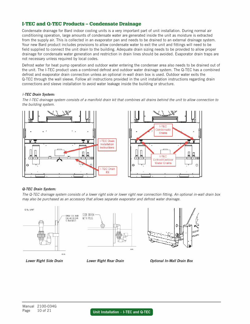
Manual 2100-034G Page 10 of 21 Unit Installation – I-TEC and Q-TEC
I-TEC Drain System:The I-TEC drainage system consists of a manifold drain kit that combines all drains behind the unit to allow connection to the building system.
Q-TEC Drain System:The Q-TEC drainage system consists of a lower right side or lower right rear connection fitting. An optional in-wall drain box may also be purchased as an accessory that allows separate evaporator and defrost water drainage.
Lower Right Side Drain Lower Right Rear Drain Optional In-Wall Drain Box
I-TEC and Q-TEC Products – Condensate DrainageCondensate drainage for Bard indoor cooling units is a very important part of unit installation. During normal air conditioning operation, large amounts of condensate water are generated inside the unit as moisture is extracted from the supply air. This is collected in an evaporator pan and needs to be drained to an external drainage system. Your new Bard product includes provisions to allow condensate water to exit the unit and fittings will need to be field supplied to connect the unit drain to the building. Adequate drain sizing needs to be provided to allow proper drainage for condensate water generation and restriction in drain lines should be avoided. Evaporator drain traps are not necessary unless required by local codes.
Defrost water for heat pump operation and outdoor water entering the condenser area also needs to be drained out of the unit. The I-TEC product uses a combined defrost and outdoor water drainage system. The Q-TEC has a combined defrost and evaporator drain connection unless an optional in-wall drain box is used. Outdoor water exits the Q-TEC through the wall sleeve. Follow all instructions provided in the unit installation instructions regarding drain connections and sleeve installation to avoid water leakage inside the building or structure.

Manual 2100-034G Page 11 of 21Unit Installation – Electrical
All Products – Power Supply VerificationIt is very important to follow all electrical and mechanical safety guidelines and instructions provided in the product installation instructions. Failure to do so may result in death, injury or product damage.
A proper power supply to your new Bard unit is very important. Be sure to verify the following with a multi-meter or other power measuring device before applying power to your Bard product.
Field-Supplied Voltage
Electrical voltage ratings and proper voltage operating ranges are provided in the unit specification sheets and installation instructions. It is important that power supplied to the unit stay in the specified operating voltage range. Voltage above or below the minimum operating value given could result in improper unit startup, unit shutdown, low unit performance, improper thermostat and unit controller operation, compressor damage and premature failure of functional parts. As a general guideline, it is always best if the power source for the unit supplies the nominal electrical rating value given in the specification sheets, installation instructions and unit serial plate for the product being used. To do so will provide the best unit performance possible from your new Bard product.
Single and Three Phase Power
Bard products are available in single and three phase power options. It is important to connect the proper phase listed on the unit serial plate. Three phase power is often used to reduce energy usage, and units rated for 3 phase operation are equipped with a phase monitor safety device. The phase monitor will not allow unit operation with improper phase connection and a red LED light on the monitor indicates phase wiring issues. Connecting 3 phase power to a single phase unit will result in component damage and improper unit operation. Connecting single phase power to a 3 phase unit will also result in component damage and improper unit operation.
Hertz (Frequency)
Bard products are available in 50hz and 60hz power options. It is important to connect power with the proper hz value listed on the unit serial plate. 60hz power is often used in the United States and Canada and units rated for 50hz operation are normally for international sales outside of this area. Connecting 50hz power to a 60hz unit not rated for 50hz operation may result in component damage and improper unit operation. Some equipment may be rated for 50/60hz operation. Review the unit specifications and installation instructions for further information regarding the power requirements of the unit.
The product installation instructions and unit specification sheets contain additional information regarding unit electrical data. This information may be accessed at www.bardhvac.com.
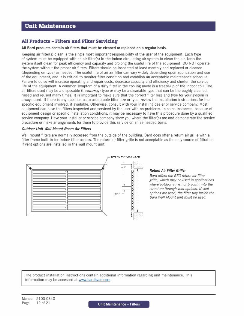
Manual 2100-034G Page 12 of 21 Unit Maintenance – Filters
All Products – Filters and Filter ServicingAll Bard products contain air filters that must be cleaned or replaced on a regular basis.
Keeping air filter(s) clean is the single most important responsibility of the user of the equipment. Each type of system must be equipped with an air filter(s) in the indoor circulating air system to clean the air, keep the system itself clean for peak efficiency and capacity and prolong the useful life of the equipment. DO NOT operate the system without the proper air filters. Filters should be inspected at least monthly and replaced or cleaned (depending on type) as needed. The useful life of an air filter can vary widely depending upon application and use of the equipment, and it is critical to monitor filter condition and establish an acceptable maintenance schedule. Failure to do so will increase operating and repair costs, decrease capacity and efficiency and shorten the service life of the equipment. A common symptom of a dirty filter in the cooling mode is a freeze-up of the indoor coil. The air filters used may be a disposable (throwaway) type or may be a cleanable type that can be thoroughly cleaned, rinsed and reused many times. It is important to make sure that the correct filter size and type for your system is always used. If there is any question as to acceptable filter size or type, review the installation instructions for the specific equipment involved, if available. Otherwise, consult with your installing dealer or service company. Most equipment can have the filters inspected and serviced by the user with no problems. In some instances, because of equipment design or specific installation conditions, it may be necessary to have this procedure done by a qualified service company. Have your installer or service company show you where the filter(s) are and demonstrate the service procedure or make arrangements for them to provide this service on an as-needed basis.
Outdoor Unit Wall Mount Room Air Filters
Wall mount filters are normally accessed from the outside of the building. Bard does offer a return air grille with a filter frame built-in for indoor filter access. The return air filter grille is not acceptable as the only source of filtration if vent options are installed in the wall mount unit.
The product installation instructions contain additional information regarding unit maintenance. This information may be accessed at www.bardhvac.com.
Return Air Filter Grille: Bard offers the RFG return air filter grille, which may be used in applications where outdoor air is not brought into the structure through vent options. If vent options are used, the filter tray inside the Bard Wall Mount unit must be used.
Unit Maintenance
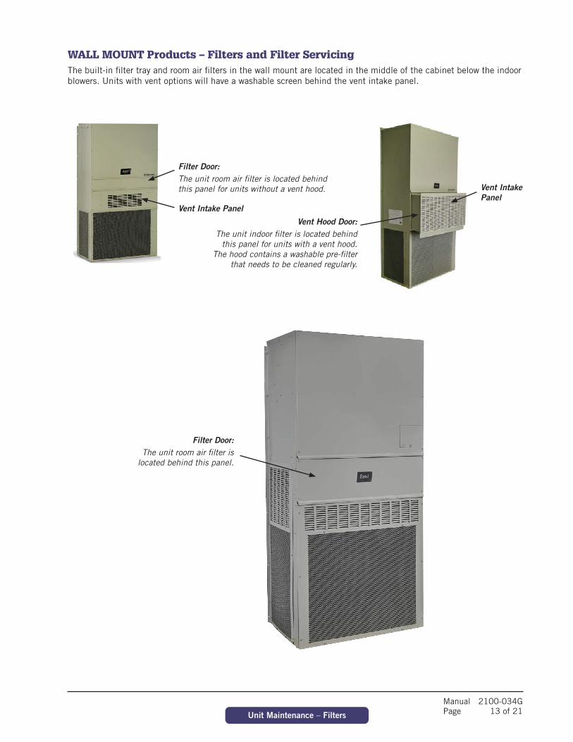
Manual 2100-034G Page 13 of 21Unit Maintenance – Filters
WALL MOUNT Products – Filters and Filter ServicingThe built-in filter tray and room air filters in the wall mount are located in the middle of the cabinet below the indoor blowers. Units with vent options will have a washable screen behind the vent intake panel.
Filter Door: The unit room air filter is located behind this panel for units without a vent hood.
Vent Hood Door: The unit indoor filter is located behind
this panel for units with a vent hood. The hood contains a washable pre-filter
that needs to be cleaned regularly.
Vent Intake Panel
Vent Intake Panel
Filter Door: The unit room air filter is
located behind this panel.
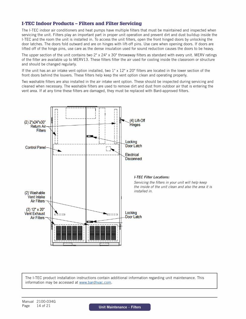
Manual 2100-034G Page 14 of 21 Unit Maintenance – Filters
I-TEC Indoor Products – Filters and Filter ServicingThe I-TEC indoor air conditioners and heat pumps have multiple filters that must be maintained and inspected when servicing the unit. Filters play an important part in proper unit operation and prevent dirt and dust buildup inside the I-TEC and the room the unit is installed in. To access the unit filters, open the front hinged doors by unlocking the door latches. The doors fold outward and are on hinges with lift-off pins. Use care when opening doors. If doors are lifted off of the hinge pins, use care as the dense insulation used for sound reduction causes the doors to be heavy.
The upper section of the unit contains two 2" x 24" x 30" throwaway filters as standard with every unit. MERV ratings of the filter are available up to MERV13. These filters filter the air used for cooling inside the classroom or structure and should be changed regularly.
If the unit has an air intake vent option installed, two 1" x 12" x 20" filters are located in the lower section of the front doors behind the louvers. These filters help keep the vent option clean and operating properly.
Two washable filters are also installed in the air intake vent option. These should be inspected during servicing and cleaned when necessary. The washable filters are used to remove dirt and dust from outdoor air that is entering the vent area. If at any time these filters are damaged, they must be replaced with Bard-approved filters.
I-TEC Filter Locations: Servicing the filters in your unit will help keep the inside of the unit clean and also the area it is installed in.
The I-TEC product installation instructions contain additional information regarding unit maintenance. This information may be accessed at www.bardhvac.com.

Manual 2100-034G Page 15 of 21Unit Maintenance – Filters
Q-TEC Indoor Products – Filters and Filter ServicingThe Q-TEC indoor air conditioners and heat pumps have two room air filters that must be replaced when servicing the unit. Filters play an important part in proper unit operation and prevent dirt and dust buildup inside the Q-TEC and the room the unit is installed in. To access the unit filters, open the front hinged door by unlocking the door latch. The door folds outward and is on hinges with lift-off pins. Use care when opening doors. If the door is lifted off of the hinge pins, use care as the insulation and louver grille cause the door to be heavy.
The upper section of the Q-TEC contains two 1" throwaway filters standard with every unit. These filters filter the air used for cooling inside the classroom or structure and should be changed regularly.
The Q-TEC product installation instructions contain additional information regarding unit maintenance. This information may be accessed at www.bardhvac.com.
Q-TEC Filter Location: The Q-TEC room air filters are located behind this hinged door. Unlock door latch and remove screw to open door.
Screw location
Pre-filter location
The Q-TEC will have a permanent pre-filter installed inside the wall sleeve if air intake vent options are inside the unit. The pre-filter must be inspected and cleaned when necessary. The easiest way to remove the pre-filter is through the outdoor louver. Clean the pre-filter with soapy water.
QWS Unit QH/QA Unit
Filter locations

Manual 2100-034G Page 16 of 21 Condenser Coil Cleaning
All Products – Coil CleaningThe outdoor coil must be kept clean and free of any airborne debris, which can accumulate over time. Large volumes of air are circulated over the coil, and airborne debris such as lint, dust, materials shed from trees, paper or other types of airborne material that can become airborne can collect on the entering coil surface. The outdoor coil must dissipate heat during the cooling mode and for a heat pump, also absorb heat during the heating mode. If the coil is dirty and matted with debris, the airflow across the coil will be reduced causing poor performance, increased operating run time and associated utility bills and in extreme conditions can shorten the useful life of the equipment.
Depending on the specific equipment involved, the surface that can accumulate debris can be on the opposite side that is exposed to view when standing in front of the machine. Closely review the machine when operating to see which direction or path the airflow takes as it moves through the machine. If the air inlet side of the coil is hidden, try to observe the back (hidden) side by looking into the side grilles, using a flashlight if necessary. While the user of the equipment needs to be aware of the potential of clogging of the outdoor coil surface, actual cleaning of the outdoor coil should not be attempted under most circumstances. If the user should attempt this procedure on their own, never do so without first having the installing dealer or service company instruct you in the proper procedure and technique.
The product installation instructions contain additional information regarding unit coil cleaning. This information may be accessed at www.bardhvac.com.
WARNING: Do not open or enter the equipment without first turning off the electrical service disconnect. Failure to do so can result in personal injury due to moving parts and/or electric shock hazard resulting in death.
Other conditions that can cause reduction of airflow across the outdoor coil are flowers, shrubbery or other growth too near the outdoor coil air inlet and outlet openings. These living things, especially as they mature and grow, will be just as effective in blocking the airflow and create the same problems as will stacking things against the equipment. These conditions can be easily managed and controlled by the user, as they do not require actually entering into the equipment enclosure, which should only be done by qualified service technicians.
Equipment Corrosion Protection
1. Avoid having any lawn sprinkler spray directly on the equipment, especially if from a brackish water source.
2. In coastal areas or corrosive environments, locate equipment as far away from the corrosion source as feasible. Units exposed directly to salt spray should be coated by a secondary protective coating operation to reduce corrosion on copper tubing, fasteners, motors and other metal parts. Coils should be ordered with a corrosion protective coating. Contact Bard for coating options.
3. Frequent cleaning and waxing of the cabinet using a good automobile polish will help extend its original appearance and protect painted surfaces.
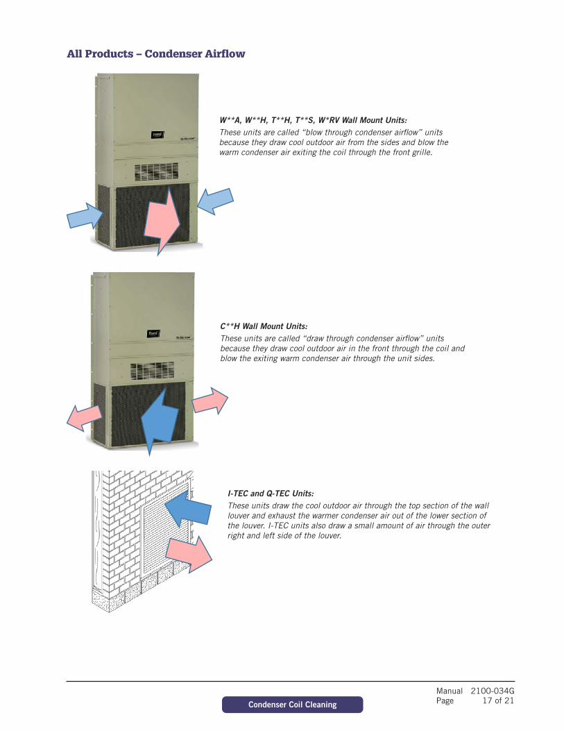
Manual 2100-034G Page 17 of 21Condenser Coil Cleaning
All Products – Condenser Airflow
W**A, W**H, T**H, T**S, W*RV Wall Mount Units: These units are called “blow through condenser airflow” units because they draw cool outdoor air from the sides and blow the warm condenser air exiting the coil through the front grille.
C**H Wall Mount Units: These units are called “draw through condenser airflow” units because they draw cool outdoor air in the front through the coil and blow the exiting warm condenser air through the unit sides.
I-TEC and Q-TEC Units:These units draw the cool outdoor air through the top section of the wall louver and exhaust the warmer condenser air out of the lower section of the louver. I-TEC units also draw a small amount of air through the outer right and left side of the louver.
Manual 2100-034G Page 18 of 21 Unit Modes of Operation
Air-to-Air Cooling Products (Air Conditioners)The cooling mode operates similar to a refrigerator, removing heat from inside the conditioned space and rejecting it outside of the space being controlled. There are three main parts of the system:
1. The evaporator (indoor) coil where cold refrigerant absorbs heat from the air, which circulates from the conditioned space through the machine and is returned to the space at a lower temperature and with some of the humidity (moisture) removed. The moisture exits through a condensate drain system. A motor/blower assembly moves the indoor air through the system.
2. The compressor, which is a sealed pump that moves the refrigerant through the system.
3. The condenser (outdoor) coil where the heat that was absorbed from the indoor space is discharged to the outdoor environment. A motor/fan system moves the outdoor air across the condenser coil. A properly sized air conditioner cannot cool a structure off rapidly and instead will pull down the temperature slowly. It also will remove a certain amount of moisture (humidity) from the circulating airstream in the process. It may take several hours to pull down a hot, moist building or structure on initial startup or anytime the system has been turned off for a long period of time. It is generally best to set the thermostat at a comfortable temperature and let it control the system as needed, rather than turning it on and off.
Moisture (humidity) removal with a conventional air conditioner (cooling) unit, or heat pump when operating in the cooling mode, is not directly controlled and is a by-product of the unit operating to control temperature in response to the temperature (thermostat) control device. Oversized equipment can easily control temperature but will have short run-times, thus reducing its ability to remove moisture from the circulating air stream.
There are also many additional influences that can affect humidity levels within the conditioned space such as laundry appliances, cooking, showers, exhaust fans and any other items that can generate moisture or affect its removal from the space. Therefore, while operation of the air conditioning or heat pump system in the cooling mode will remove some amount of moisture as it reduces the air temperature, precise humidity regulation in the conditioned space cannot be assured and additional equipment such as a dedicated dehumidifier may be required.
Air-to-Air Cooling and Heating Products (Heat Pumps)A heat pump is a refrigerant-based system that has additional components and controls that both heats and cools using a compressor for both modes of operation. Most heat pumps will also be equipped with some amount of electric heat to supplement the heating capacity of the compressor system on an as-needed basis. This operation is entirely automatic and is controlled by the indoor thermostat and possibly also an outdoor thermostat.
Cooling Mode
The cooling mode of a heat pump is exactly the same as that described for an air conditioner in the above section.
Heating Mode
The system operates in reverse cycle, meaning that it absorbs and moves heat from the outdoors and transfers it indoors to be rejected into the circulating air stream. Even though it seems cold to humans, there is usable heat that can be extracted efficiently from the outdoor air down to 0ºF, although the colder the air is there is less heat to extract and the operating efficiency is diminished.
Defrost Cycle
When operating in the heating mode, the outdoor coil will be colder than the outdoor air that is forced over it by the fan system. When the outdoor air temperature is above approximately 40°F, moisture can accumulate on the coil and it will drain down and out the base of the unit. As the air temperature gets below approximately 40°F, the coil temperature will start to drop below 32°F, and frost or ice will begin to form on the coil.
An automatic defrost system keeps track of system run time when the outdoor coil temperature is in the freezing zone and will initiate a defrost cycle at the appropriate time. The unit continues to operate during the defrost cycle, but the outdoor fan motor will stop and the reversing valve will shift positions to flow hot refrigerant gas through the outdoor coil to melt the accumulated frost. Water will start to drain freely from the unit, and steam may be emitted from the unit.
The length of the defrost cycle will vary depending upon actual outdoor temperature, humidity levels and amount of accumulated frost. It could range from 1-2 minutes up to but not exceeding 8 minutes. When the defrost cycle
Unit Operation
Manual 2100-034G Page 19 of 21Unit Modes of Operation
terminates, the reversing valve will shift back to heating mode and the outdoor fan will restart. There is typically a large puff of steam emitted as the fan restarts. When the heat pump shifts from cool to heating mode, from heating to cooling mode and especially during defrost cycles, there will be a pressure transfer sound heard as the reversing valve redirects the flow of refrigerant. This is commonly described as a hissing noise and is a normal sound for this type equipment.
For air source heat pumps, it is important to keep heavy snow from accumulating around the machine to the point of blocking the inlet and outlet openings to the outdoor coil section. For wall mounted or other equipment that is elevated, this should not be a factor; but for equipment installed on or near the ground, this can be an issue in areas prone to heavy and/or blowing snow. The air source heat pump cannot operate effectively and efficiently when snowbound just as a car cannot function well in heavy snow conditions.
Water-to-Air Cooling and Heating Products (Geothermal Heat Pumps)These types of heat pumps are also commonly referred to as water source or geothermal systems. Just like the air source heat pump, they are refrigerant-based systems that both heat and cool using a compressor for both modes of operation. The primary difference is that the system uses water or antifreeze-protected water solution instead of an air-cooled outdoor heat transfer coil, and there is no outdoor motor/fan system but instead a water pump to provide adequate water flow to the system.
Cooling Mode
The cooling mode of a water-to-air heat pump is exactly the same as that described for an air conditioner in the previous Air Conditioner section, except that the outdoor coil uses water instead of air for the heat transfer medium.
Heat Mode
The system operates in reverse cycle, meaning that it acquires and moves heat from the water supply flowing through the water to refrigerant coil and transfers it indoors to be rejected into the circulating air stream.
Most water-to-air heat pumps (but not all) will also be equipped with some amount of electric heat to supplement the heating capacity of the compressor system on an as-needed basis. This operation is entirely automatic and is controlled by the indoor thermostat.
Because of the design of water-to-air heat pumps and the water temperatures involved, no defrost system is required as in air-to-air heat pumps.
Water Supply Systems
Depending upon the type and application of the water-to-air heat pump, the water side of the system could be one of the following:
1. Individual closed loop buried in a trench or vertical bore hole(s).
2. Individual loop submerged in a pond.
3. Water supplied from a well and discharged into pond, stream, ditch or another well.
4. Water supplied from a boiler/tower system, typically only in larger multi-unit installations.
Manual 2100-034G Page 20 of 21 Dehumidification and Ventilation Operation
Dehumidification (Air-to-Air or Water-to-Air Systems)Many Bard systems, typically those used in schools or other commercial applications, have a dedicated dehumidification capability by having a special additional refrigeration circuit (factory-installed option only) in addition to the basic system. These special systems, sometimes also referred to as hot gas reheat, are designed to control humidity on demand from a humidity controller much the same as the basic cooling and/or heating system is controlled by a wall thermostat. Consult your installer and/or service company to determine if your installation has any of these devices and for any instructions or maintenance requirements you should be aware of as the user.
Ventilation Options (Air-to-Air or Water-to-Air Systems)All Bard systems are available with factory-installed vent options. Most units can have ventilation field installed after unit installation.
Ventilation has multiple purposes:
• Outside air intake for occupied structures• Positive pressurization• Energy savings when outdoor air can be used for cooling• Agricultural use of bringing in outdoor air and exhausting room air• Equipment and electronics ventilation
Review product specifications and manuals for more details regarding available ventilation options and features. Product documentation is shipped with the product and also available at www.bardhvac.com.
Dehumidification and Ventilation Operation

Manual 2100-034G Page 21 of 21
All Units – TroubleshootingYour Bard product is made to operate for many trouble-free years if installed properly and maintenance practices are followed. Be sure to verify that all filters are clean, and condenser coils are free of dirt and debris. Often these items may look clean at first, but upon closer inspection, show signs of dirt and debris build-up. New units on new structures may have dirt and dust in filters from the building construction process.
Thermostats and unit controllers often contain vent holes for proper sensor measurement inside the device. Make sure the thermostat or controller are not full of dirt and dust from building construction or years of use.
Verify all requirements in the installation instructions and specification sheets are met. Unit voltages, airflow clearance requirements and clean unit power without brownouts or spikes play a critical role in unit performance. If 208 VAC power is supplied to the unit, the 208V tap must be used on the 24 VAC transformer located inside the control panel. Common sense must also be used when installing the unit in an environment that may put the unit at risk of improper operation.
Helpful Hints and Good Operating PracticesThe following information will help you enjoy the full comfort and benefits of your Bard cooling and heating system, maximize the performance and efficiency and help extend the life of your system.
1. Always keep the equipment in peak operating condition with routine scheduled maintenance, especially for the air filters, and to assure a clean outdoor coil.
2. For most efficient operation, set the thermostat at the temperature you prefer and then let it take control. If any changes to the settings are required, they should be made in small adjustments and the system be allowed time to respond. Rapid changes either up or down should not be done.
3. Setting the thermostat very high does not make the system heat faster and setting it very low does not make it cool faster.
4. It is not recommended to turn the system "Off" then back "On" when you need it. This can allow temperature and humidity to build up in warm weather conditions and force the system to run continuously to try and catch up. If the building is to be unoccupied for a lengthy period, it is best to adjust the thermostat to a reasonable higher (or lower—depending on the season) setting rather than turning it completely off. Upon return, the inside conditions will not be totally out of control and recovery time to desired conditions would be much shorter.
5. Airflow inside the room or building is very important. Keep all supply registers open and all returns free and unrestricted. Avoid placing objects in areas that will hinder unit airflow. The heating and cooling system is designed to have a certain amount of airflow for proper operation. Therefore, closing off registers, in unused rooms as an example, could reduce airflow below acceptable levels and should not be done without review by your service company who can assess the overall situation and advise you accordingly.
6. Heat pumps, especially air-to-air heat pumps, may have the system (compressor) run continuously at lower outdoor temperatures, and this is normal. The heat pump (compressor) mode is controlled by the beginning stages of the thermostat and delivers the most efficient heat. As the outdoor temperature drops off, the heat pump mode heat will also diminish (because there is less heat in the outdoor air to absorb) and must be supplemented by additional electric heat stages, which are not as efficient as the heat pump. The thermostat automatically controls everything and the backup heat will only operate on demand as needed to maintain the desired temperature.
7. The thermostat or controller is the user's primary connection to the system so it is very important to have a thorough understanding of how it works and how to use it properly. Have your installer or service company explain and demonstrate proper operation of the controls.
8. Make sure you thoroughly understand how the heating and cooling system itself is intended to operate and what to expect from it. Have your installer or service company explain and demonstrate proper operation of the heating and cooling system.
Troubleshooting
Troubleshooting