little thompson water district
TRANSCRIPT

Little Thompson Water District Section VI Water Line Specifications
LITTLE THOMPSON WATER DISTRICT
SECTION VI WATER LINE SPECIFICATIONS
March 4, 2004

Little Thompson Water District Section VI Water Line Specifications i
SECTION VI WATER LINE SPECIFICATIONS TABLE OF CONTENTS
600 DISTRICT WATER LINE SPECIFICATIONS .......................................... 600.1-1
600.1 GENERAL.................................................................................................... 600.1-1
A. Scope......................................................................................................................... 600.1-1 B. Documents ................................................................................................................ 600.1-2 C. Definitions .................................................................................................................600.1.2 D. Abbreviations............................................................................................................ 600.1-5 E. Coordination With the District ................................................................................. 600.1-5 F. Notification ............................................................................................................... 600.1-6 G. Special Requirements ............................................................................................... 600.1-7 H. Warranty ................................................................................................................... 600.1-8 I. Easements ................................................................................................................. 600.1-8 J. Rebates...................................................................................................................... 600.1-8 K. Permits ...................................................................................................................... 600.1-8 L. Patent Fees and Royalties ......................................................................................... 600.1-9 M. Liens ......................................................................................................................... 600.1-9 N. State and Local Laws................................................................................................ 600.1-9 O. Construction Drawings ............................................................................................. 600.1-9
1. Plan Review.................................................................................................. 600.1-9 2. Construction Drawing Requirements ......................................................... 600.1-10 3. Project Manual Requirements..................................................................... 600.1-10 4. Approved Construction Drawings .............................................................. 600.1-11 5. As-Built Drawings ...................................................................................... 600.1-11 6. Minimum Construction Drawing Standards............................................... 600.1-11
P. Contractors and Insurance ...................................................................................... 600.1-12 1. General........................................................................................................ 600.1-12 2. Workmen's Compensation Insurance ......................................................... 600.1-12 3. Public Liability and Property Damage Insurance....................................... 600.1-12 4. Proof of Insurance....................................................................................... 600.1-12 5. The Term of Insurance Required................................................................ 600.1-13
Q. Safety ...................................................................................................................... 600.1-13 1. Contractor ................................................................................................... 600.1-13 2. District ........................................................................................................ 600.1-13
R. Quality Control ....................................................................................................... 600.1-14 1. General........................................................................................................ 600.1-14 2. Halting Construction................................................................................... 600.1-14 3. Required Inspections .................................................................................. 600.1-15 4. Exploratory Excavation .............................................................................. 600.1-15 5. Final Walk-Through ................................................................................... 600.1-15 6. Final Acceptance ........................................................................................ 600.1-16 7. Placing in Service ....................................................................................... 600.1-16
600.2 DISTRIBUTION SYSTEM DESIGN AND LAYOUT............................... 600.2-1
A. Sizing Distribution Mains......................................................................................... 600.2-1 B. Layout of Distribution System.................................................................................. 600.2-1 C. Water Line Looping Policy ...................................................................................... 600.2-3 D. Water Line Oversizing Policy .................................................................................. 600.2-3

Little Thompson Water District Section VI Water Line Specifications ii
1. General.......................................................................................................... 600.2-3 2. Summary of Policy ....................................................................................... 600.2-3 3. Water Line Size ............................................................................................ 600.2-4 4. Determining if Oversizing Is Required......................................................... 600.2-5 5. District Participation in Oversizing Project .................................................. 600.2-5 6. Calculating District Participation ................................................................. 600.2-5
E. Operating Pressures .................................................................................................. 600.2-8 F. Pressure Reducing Stations....................................................................................... 600.2-8 G. Storage Facilities ...................................................................................................... 600.2-9 H. Pumping Facilities .................................................................................................... 600.2-9
1. District Facilities......................................................................................... 600.2-10 2. Non District Facilities................................................................................. 600.2-10
I. Valves ..................................................................................................................... 600.2-10 1. Locations..................................................................................................... 600.2-10 2. Type of Valves............................................................................................ 600.2-12
J. Connections to Transmission Lines........................................................................ 600.2-12 K. Interconnections to Other Water Systems .............................................................. 600.2-13
1. Temporary Hose Connections .................................................................... 600.2-13 2. Permanent Emergency Connections ........................................................... 600.2-13 3. Permanent Master Meter Connections........................................................ 600.2-14
L. SCADA System...................................................................................................... 600.2-14 1. General........................................................................................................ 600.2-14 2. Equipment and Instruments ........................................................................ 600.2-14 3. Installation .................................................................................................. 600.2-23
M. Fire Protection ........................................................................................................ 600.2-23 1. General........................................................................................................ 600.2-23 2. Fire Protection Agencies............................................................................. 600.2-25 3. Location ...................................................................................................... 600.2-25 4. Fire Hydrants .............................................................................................. 600.2-25 5. Fire Sprinkler Lines .................................................................................... 600.2-26
N. Cross Connection Control....................................................................................... 600.2-26 O. Backflow Prevention Program................................................................................ 600.2-26
600.3 SERVICE LINES AND APPURTENANCES............................................. 600.3-1
A. General...................................................................................................................... 600.3-1 B. Ownership and Maintenance .................................................................................... 600.3-1
1. Ownership..................................................................................................... 600.3-1 2. Maintenance.................................................................................................. 600.3-1
C. Layout ....................................................................................................................... 600.3-1 1. Location ........................................................................................................ 600.3-1 2. Depth............................................................................................................. 600.3-2 3. Compaction................................................................................................... 600.3-2 4. Length ........................................................................................................... 600.3-3
D. Separate Trenches..................................................................................................... 600.3-3 E. Combination Service Lines....................................................................................... 600.3-3 F. Pumps ....................................................................................................................... 600.3-3 G. Connections for Water.............................................................................................. 600.3-3 H. Taps, Saddles and Sleeves ........................................................................................ 600.3-4 I. Size ........................................................................................................................... 600.3-4 J. Pipe Material............................................................................................................. 600.3-5 K. Meters ....................................................................................................................... 600.3-5

Little Thompson Water District Section VI Water Line Specifications iii
600.4 MATERIALS ............................................................................................... 600.4-1
A. General...................................................................................................................... 600.4-1 B. Pipe ........................................................................................................................... 600.4-2
1. Size of Mains ................................................................................................ 600.4-2 2. Size of Service Lines .................................................................................... 600.4-2 3. Pipe Class...................................................................................................... 600.4-2 4. Selection of Pipe ........................................................................................... 600.4-2
C. Pipe Fittings .............................................................................................................. 600.4-3 1. Joints ............................................................................................................. 600.4-3 2. Closure Fittings............................................................................................. 600.4-3 3. Miscellaneous Pipe Fittings.......................................................................... 600.4-3 4. Clamps, Rods and Joint Restraint Devices ................................................... 600.4-3
D. Valves ....................................................................................................................... 600.4-4 1. In-Line Valves .............................................................................................. 600.4-4 2. Pressure Regulating Valves .......................................................................... 600.4-4 3. Tapping Valves and Sleeves......................................................................... 600.4-5 4. Check Valves ................................................................................................ 600.4-5 5. Meter Check Valve ....................................................................................... 600.4-5 6. Valves for Use with Meters .......................................................................... 600.4-5 7. Corporation Stops ......................................................................................... 600.4-6 8. Curb Stops .................................................................................................... 600.4-6 9. Combination Air Valves ............................................................................... 600.4-6 10. Valve Boxes.................................................................................................. 600.4-7
E. Control of Backflow and Cross Connection............................................................. 600.4-7 1. Backflow Prevention .................................................................................... 600.4-7 2. Cross Connection Control............................................................................. 600.4-7
F. Marker Posts ............................................................................................................. 600.4-7 G. Meters ....................................................................................................................... 600.4-7
1. General.......................................................................................................... 600.4-7 2. Size of Meter................................................................................................. 600.4-8 3. Type of Meter ............................................................................................... 600.4-8
H. Meter Pits and Setters ............................................................................................... 600.4-8 1. Master Meters ............................................................................................... 600.4-8 2. Service Meter Setters.................................................................................... 600.4-9 3. Radio Read System....................................................................................... 600.4-9 4. Meter Bypass Lines ...................................................................................... 600.4-9 5. Meter Couplings ........................................................................................... 600.4-9 6. Meter Setter .................................................................................................. 600.4-9 7. Valve and Meter Supports ............................................................................ 600.4-9 8. Residential Meter Pits and Covers.............................................................. 600.4-10
I. Vaults and Manholes .............................................................................................. 600.4-10 1. Vaults.......................................................................................................... 600.4-10 2. Manholes..................................................................................................... 600.4-10 3. Concrete...................................................................................................... 600.4-11 4. Sump Pits .................................................................................................... 600.4-11 5. Vent Pipes................................................................................................... 600.4-11
J. Fire Hydrants and Fire Lines .................................................................................. 600.4-11 1. Fire Hydrants .............................................................................................. 600.4-11 2. Fire Lines .................................................................................................... 600.4-12
K. Service Lines .......................................................................................................... 600.4-12

Little Thompson Water District Section VI Water Line Specifications iv
L. Corrosion Protection Systems................................................................................. 600.4-12 M. Thrust Blocks.......................................................................................................... 600.4-12 N. Casing Pipe ............................................................................................................. 600.4-13
600.5 EARTHWORK............................................................................................. 600.5-1
A. Definition.................................................................................................................. 600.5-1 B. Exploratory Excavation ............................................................................................ 600.5-1 C. Alignment and Grade................................................................................................ 600.5-1 D. Trenching Operations ............................................................................................... 600.5-1
1. Trench Width ................................................................................................ 600.5-1 2. Trench Support ............................................................................................. 600.5-1
E. Excavation for Structures ......................................................................................... 600.5-1 F. Surplus Excavation Material..................................................................................... 600.5-1 G. Blasting ..................................................................................................................... 600.5-2 H. Dewatering................................................................................................................ 600.5-2 I. Foundations on Unstable Soil................................................................................... 600.5-3 J. Pipe Bedding and Pipe Zone Material ...................................................................... 600.5-3 K. Backfill and Compaction .......................................................................................... 600.5-3 L. Flowable Concrete Backfill ...................................................................................... 600.5-3 M. Clean Up ................................................................................................................... 600.5-3 N. Subgrade and Road Preparation................................................................................ 600.5-4 O. Compaction............................................................................................................... 600.5-5 P. Surface Restoration................................................................................................... 600.5-5
1. Unsurfaced Areas.......................................................................................... 600.5-5 2. Surfaced Areas.............................................................................................. 600.5-5 3. Easements, Cultivated or Agricultural Areas ............................................... 600.5-5 600.6 WATER LINE DISINFECTION AND TESTING ...................................... 600.6-1
A. Disinfection............................................................................................................... 600.6-1 1. General.......................................................................................................... 600.6-1 2. Materials ....................................................................................................... 600.6-1
B. Filling Pipe................................................................................................................ 600.6-1 C. Preliminary Flushing ................................................................................................ 600.6-1 D. Methods of Disinfection ........................................................................................... 600.6-2
1. General.......................................................................................................... 600.6-2 2. Tablet Method............................................................................................... 600.6-2 3. Continuous Feed Method.............................................................................. 600.6-3 4. Slug Method.................................................................................................. 600.6-4 5. Disinfection for Repair of Existing Mains.................................................... 600.6-5
E. Final Flushing ........................................................................................................... 600.6-5 F. Bacteriological Testing............................................................................................. 600.6-5 G. Repetition of Procedure ............................................................................................ 600.6-5 H. Hydrostatic Testing................................................................................................... 600.6-6
1. Description.................................................................................................... 600.6-6 2. Pressure Test ................................................................................................. 600.6-6 600.7 CONNECTION TO EXISTING MAINS AND REPAIRS.......................... 600.7-1
A. Connection to Existing Mains .................................................................................. 600.7-1 1. Utility Verification........................................................................................ 600.7-1 2. Notification ................................................................................................... 600.7-1 3. Connection.................................................................................................... 600.7-1

Little Thompson Water District Section VI Water Line Specifications v
4. Quality Control ............................................................................................. 600.7-1 5. Operation of Valves...................................................................................... 600.7-2
B. Repair of Water Lines............................................................................................... 600.7-2 1. Utility Verification........................................................................................ 600.7-2 2. Emergency Repair ........................................................................................ 600.7-2 4. Repair Methods............................................................................................. 600.7-2 601 MATERIALS AND INSTALLATION........................................................ 601.1-1 601.1 PVC PIPE ..................................................................................................... 601.1-1
A. General...................................................................................................................... 601.1-1 1. Description.................................................................................................... 601.1-1 2. Material Delivery, Storage and Handling..................................................... 601.1-1
B. Material..................................................................................................................... 601.1-1 1. Pipe ............................................................................................................... 601.1-1 2. Joints ............................................................................................................. 601.1-2 3. Couplings...................................................................................................... 601.1-3 4. Accessories ................................................................................................... 601.1-3
C. Installation ................................................................................................................ 601.1-3 1. Inspection...................................................................................................... 601.1-3 2. Installation .................................................................................................... 601.1-4 601.2 DUCTILE IRON PIPE AND FITTINGS..................................................... 601.2-1
A. General...................................................................................................................... 601.2-1 1. Description.................................................................................................... 601.2-1 2. Material Delivery, Storage and Handling..................................................... 601.2-1
B. Material..................................................................................................................... 601.2-1 1. Pipe ............................................................................................................... 601.2-1
a. General................................................................................................. 601.2-1 b. Pipe Size and Pressure Class ............................................................... 601.2-2 c. Pipe Length .......................................................................................... 601.2-3
2. Fittings .......................................................................................................... 601.2-3 3. Joints ............................................................................................................. 601.2-3 4. Couplings...................................................................................................... 601.2-4 5. Pipe Lining.................................................................................................... 601.2-4 6. Pipe Coating.................................................................................................. 601.2-5 7. Accessories ................................................................................................... 601.2-5
C. Installation ................................................................................................................ 601.2-5
1. Inspection...................................................................................................... 601.2-5 2. Installation .................................................................................................... 601.2-5 601.3 VALVES....................................................................................................... 601.3-1
A. General...................................................................................................................... 601.3-1 1. Description.................................................................................................... 601.3-1 2. Material Delivery, Storage and Handling..................................................... 601.3-1
B. Material..................................................................................................................... 601.3-1 1. General.......................................................................................................... 601.3-1 2. Gate Valves................................................................................................... 601.3-2 3. Butterfly Valves............................................................................................ 601.3-3 4. Ball Valves.................................................................................................... 601.3-5

Little Thompson Water District Section VI Water Line Specifications vi
5. Tapping Valves............................................................................................. 601.3-6 6. Swing Check Valves..................................................................................... 601.3-7 7. Combination Air Valves ............................................................................... 601.3-9 8. Pressure Regulating Valves ........................................................................ 601.3-10 9. Accessories ................................................................................................. 601.3-11
C. Installation .............................................................................................................. 601.3-12 1. In-Line Valves ............................................................................................ 601.3-12 2. Valve Boxes................................................................................................ 601.3-12 3. Combination Air Valves ............................................................................. 601.3-13 4. Pressure Regulating Valves ........................................................................ 601.3-13 5. Valve Operation.......................................................................................... 601.3-13 601.4 FIRE HYDRANTS AND BLOW-OFF XE "Blow-Off" S .......................... 601.4-1
A. General...................................................................................................................... 601.4-1 1. Description.................................................................................................... 601.4-1 2. Material Delivery, Storage and Handling..................................................... 601.4-1
B. Material..................................................................................................................... 601.4-1 1. Fire Hydrants ................................................................................................ 601.4-1 2. Blow-offs ...................................................................................................... 601.4-4 3. Hydrant Gravel ............................................................................................. 601.4-6
C. Installation ................................................................................................................ 601.4-6 1. Inspection...................................................................................................... 601.4-6 2. Installation .................................................................................................... 601.4-6 3. Drainage........................................................................................................ 601.4-8 4. Thrust Restraint ............................................................................................ 601.4-8 5. Backfill ......................................................................................................... 601.4-8 6. Tags............................................................................................................... 601.4-9 7. Operation ...................................................................................................... 601.4-9 601.5 TAPPING SADDLES AND SLEEVES....................................................... 601.5-1
A. General...................................................................................................................... 601.5-1 1. Description.................................................................................................... 601.5-1 2. Delivery, Storage and Handling ................................................................... 601.5-1
B. Material..................................................................................................................... 601.5-1 1. Tapping Saddles............................................................................................ 601.5-1 2. Tapping Sleeves............................................................................................ 601.5-1
C. Installation ................................................................................................................ 601.5-4 1. Tapping Saddles and Sleeves........................................................................ 601.5-4 2. Tapping Procedure........................................................................................ 601.5-4 601.6 COUPLINGS, FLANGE ADAPTORS AND REPAIR BANDS................. 601.6-1
A. General...................................................................................................................... 601.6-1 1. Description.................................................................................................... 601.6-1 2. Material Delivery, Storage and Handling..................................................... 601.6-1
B. Material..................................................................................................................... 601.6-1 1. General.......................................................................................................... 601.6-1 2. Flexible Iron Couplings ................................................................................ 601.6-1 3. Transition Couplings .................................................................................... 601.6-2 4. Insulated Couplings ...................................................................................... 601.6-2 5. Flexible PVC Couplings ............................................................................... 601.6-2 6. Flange Adaptors............................................................................................ 601.6-3

Little Thompson Water District Section VI Water Line Specifications vii
7. Repair Bands................................................................................................. 601.6-3 C. Installation ................................................................................................................ 601.6-3
601.7 SERVICE CONNECTIONS ........................................................................ 601.7-1
A. General...................................................................................................................... 601.7-1 1. Description.................................................................................................... 601.7-1 2. Material Delivery, Storage and Handling..................................................... 601.7-1 3. Maintenance and Correction......................................................................... 601.7-1 4. Developer Responsibility...............................................................................601.7-1
B. Material..................................................................................................................... 601.7-1 1. Tapping Saddles............................................................................................ 601.7-1 2. Corporation Stops ......................................................................................... 601.7-1 3. Tapping Valves............................................................................................. 601.7-2 4. Service Lines ................................................................................................ 601.7-2 5. Couplings...................................................................................................... 601.7-3 6. Curb Stops .................................................................................................... 601.7-3 7. Meter Setters................................................................................................. 601.7-3 8. Meters ........................................................................................................... 601.7-4 9. Meter Pits and Vaults.................................................................................... 601.7-4
C. Installation ................................................................................................................ 601-7.5 1. General.......................................................................................................... 601.7-5 2. Inspection...................................................................................................... 601.7-5 3. Service Taps.................................................................................................. 601.7-6 4. Corporation Stops ......................................................................................... 601.7-6 5. Service Lines ................................................................................................ 601.7-6 6. Meters, Meter Setters, and Meter Pits and Vaults ........................................ 601.7-7 601.8 VAULTS AND MANHOLES...................................................................... 601.8-1
A. General...................................................................................................................... 601.8-1 1. Description.................................................................................................... 601.8-1 2. Material Delivery, Storage and Handling..................................................... 601.8-1
B. Material..................................................................................................................... 601.8-1 1. Precast Concrete ........................................................................................... 601.8-1 2. Cast In Place Concrete.................................................................................. 601.8-1 3. Grout ............................................................................................................. 601.8-1 4. Steps.............................................................................................................. 601.8-2 5. Watertight Seals............................................................................................ 601.8-2 6. Reinforcement Material ................................................................................ 601.8-3 7. Form Material ............................................................................................... 601.8-3
C. Installation ................................................................................................................ 601.8-3 1. General.......................................................................................................... 601.8-3 2. Manholes and Vaults .................................................................................... 601.8-3 601.9 PIPE CASING, BORING AND JACKING ................................................. 601.9-1
A. General...................................................................................................................... 601.9-1 1. Description.................................................................................................... 601.9-1 2. Material Delivery, Storage and Handling..................................................... 601.9-1 3. Quality Assurance......................................................................................... 601.9-1
B. Material..................................................................................................................... 601.9-1 1. Steel Casing .................................................................................................. 601.9-1 2. Casing Seals.................................................................................................. 601.9-2
Little Thompson Water District Section VI Water Line Specifications viii
3. Casing Chocks and Skids.............................................................................. 601.9-2 4. High Density Polyethylene Pipe................................................................... 601.9-3
C. Installation ................................................................................................................ 601.9-3 1. General.......................................................................................................... 601.9-3 2. Welding......................................................................................................... 601.9-3 3. Location ........................................................................................................ 601.9-4 4. Sealing .......................................................................................................... 601.9-4 5. Casing Chocks and Skids.............................................................................. 601.9-4 6. HDPE Direct Placement ............................................................................... 601.9-4 601.10 THRUST BLOCKS AND OTHER RESTRAINTS................................... 601.10-1
A. General.................................................................................................................... 601.10-1 1. Description.................................................................................................. 601.10-1 2. Material Delivery, Storage and Handling................................................... 601.10-1
B. Material................................................................................................................... 601.10-1 1. General........................................................................................................ 601.10-1 2. Thrust Blocks.............................................................................................. 601.10-1 3. Mechanical Joint Restraint Devices............................................................ 601.10-2 4. Flange Adaptor Restraints .......................................................................... 601.10-2 5. Restrained Joint Pipe and Fittings .............................................................. 601.10-2 6. Harness Rods .............................................................................................. 601.10-3
C. Installation .............................................................................................................. 601.10-3 1. Inspection.................................................................................................... 601.10-3 2. Thrust Blocks.............................................................................................. 601.10-4 3. Mechanical Joint Restraint Devices............................................................ 601.10-5 4. Other Restraint............................................................................................ 601.10-5 601.11 TRACER WIRE ......................................................................................... 601.11-1
A. General.................................................................................................................... 601.11-1 B. Material................................................................................................................... 601.11-1
1. Tracer Wire................................................................................................. 601.11-1 2. Splices......................................................................................................... 601.11-1 3. Delivery Storage and Handling .................................................................. 601.11-1
C. Installation .............................................................................................................. 601.11-1 1. General........................................................................................................ 601.11-1 2. Service Lines .............................................................................................. 601.11-1 3. Splicing ....................................................................................................... 601.11-2 4. Bringing to Surface..................................................................................... 601.11-2 601.12 POLYETHYLENE ENCASEMENT ......................................................... 601.12-1
A. General.................................................................................................................... 601.12-1 B. Material................................................................................................................... 601.12-1 C. Installation .............................................................................................................. 601.12-1
1. Polyethylene Encasement of Pipe............................................................... 601.12-1 2. Double Encasement .................................................................................... 601.12-2 3. Polyethylene Bond Break ........................................................................... 601.12-2 601.13 CAST IN PLACE CONCRETE ................................................................. 601.13-1
A. General.................................................................................................................... 601.13-1 1. Material Delivery, Storage and Handling................................................... 601.13-1 2. Job Conditions ............................................................................................ 601.13-1

Little Thompson Water District Section VI Water Line Specifications ix
B. Material................................................................................................................... 601.13-2 1. General........................................................................................................ 601.13-2 2. Cement........................................................................................................ 601.13-2 3. Aggregates .................................................................................................. 601.13-2 4. Water........................................................................................................... 601.13-2 5. Admixtures ................................................................................................. 601.13-2 6. Forms .......................................................................................................... 601.13-3 7. Reinforcement............................................................................................. 601.13-3
C. Installation .............................................................................................................. 601.13-4 1. General........................................................................................................ 601.13-4 2. Forms .......................................................................................................... 601.13-4 3. Reinforcement............................................................................................. 601.13-4 4. Placement.................................................................................................... 601.13-4 5. Curing ......................................................................................................... 601.13-4 601.14 PRECAST CONCRETE............................................................................. 601.14-1
A. General.................................................................................................................... 601.14-1 1. Material Delivery, Storage and Handling................................................... 601.14-1
B. Material................................................................................................................... 601.14-1 1. Manholes......................................................................................................601.14.1 2. Vaults.......................................................................................................... 601.14-1 3. Concrete...................................................................................................... 601.14-1 4. Reinforcement............................................................................................. 601.14-1 5. Grout ........................................................................................................... 601.14-1 6. Steps............................................................................................................ 601.14-2 7. Preformed Plastic Gaskets .......................................................................... 601.14-2
C. Installation .............................................................................................................. 601.14-2 601.15 FLOWABLE CONCRETE BACKFILL.................................................... 601.15-1
A. General.................................................................................................................... 601.15-1 1. Material Delivery, Storage and Handling................................................... 601.15-1 2. Job Conditions............................................................................................. 601.15-1
B. Material................................................................................................................... 601.15-1 C. Installation .............................................................................................................. 601.15-2
601.16 GRAVEL SURFACING ............................................................................ 601.16-1
A. General.................................................................................................................... 601.16-1 1. Application ................................................................................................. 601.16-1
B. Material................................................................................................................... 601.16-1 1. Private Easement ........................................................................................ 601.16-1 2. Public Right-of-Way................................................................................... 601.16-1
C. Installation .............................................................................................................. 601.16-1 1. Private Easement ........................................................................................ 601.16-1 2. Public Right-of-Way................................................................................... 601.16-2
601.17 ASPHALT PAVEMENT............................................................................ 601.17-1
A. General.................................................................................................................... 601.17-1 1. Material Delivery, Storage and Handling................................................... 601.17-1 2. Quality Assurance....................................................................................... 601.17-1
B. Material................................................................................................................... 601.17-1 1. Private Easement ........................................................................................ 601.17-1

Little Thompson Water District Section VI Water Line Specifications x
2. Public Right-of-Way................................................................................... 601.17-2 C. Installation .............................................................................................................. 601.17-2
1. Private Easement ........................................................................................ 601.17-2 2. Public Right-of-Way................................................................................... 601.17-2
601.18 PIPE INSTALLATION.............................................................................. 601.18-1
A. General.................................................................................................................... 601.18-1 1. Quality Assurance....................................................................................... 601.18-1 2. Installation .................................................................................................. 601.18-1
B. Material................................................................................................................... 601.18-3 1. Pipe ............................................................................................................. 601.18-3 2. Valves ......................................................................................................... 601.18-3 3. Fire Hydrants and Blow-Offs ..................................................................... 601.18-3 4. Service Lines, Meters and Appurtenances.................................................. 601.18-4 5. Tapping Saddles and Sleeves...................................................................... 601.18-4
C. Installation .............................................................................................................. 601.18-4 1. PVC Pipe Installation ................................................................................. 601.18-4 2. Ductile Iron Pipe Installation...................................................................... 601.18-6 3. Pipe Laying................................................................................................. 601.18-9 4. Clean Up ................................................................................................... 601.18-12 5. Installation of Pipeline Appurtenances..................................................... 601.18-12
601.19 TRENCHING, BACKFILLING AND COMPACTING ........................... 601.19-1
A. General.................................................................................................................... 601.19-1 1. Classification of Excavated Material.......................................................... 601.19-1 2. Quality Assurance....................................................................................... 601.19-1 3. Job Conditions ............................................................................................ 601.19-2 4. Maintenance and Correction....................................................................... 601.19-5
B. Material................................................................................................................... 601.19-5 1. Stabilization Material.................................................................................. 601.19-5 2. Bedding Material ........................................................................................ 601.19-6 3. Groundwater Barrier Material ................................................................... 601.19-7 4. Trench Backfill Material............................................................................. 601.19-7
C. Installation .............................................................................................................. 601.19-8 1. Preparation.................................................................................................. 601.19-8 2. Excavation .................................................................................................. 601.19-9 3. Pipe Bedding............................................................................................. 601.19-11 4. Backfilling and Compacting ..................................................................... 601.19-12 5. Excess Material......................................................................................... 601.19-13 6. Field Quality Control................................................................................ 601.19-13
601.20 ROCK EXCAVATION.............................................................................. 601.20-1
A. General.................................................................................................................... 601.20-1 1. Definitions .................................................................................................. 601.20-1 2. Regulatory Requirements ........................................................................... 601.20-1 3. Scheduling .................................................................................................. 601.20-1
B. Material................................................................................................................... 601.20-1 C. Excavation .............................................................................................................. 601.20-2
1. Preparation.................................................................................................. 601.20-2 2. Mechanical Method .................................................................................... 601.20-2 3. Explosive Method....................................................................................... 601.20-2

Little Thompson Water District Section VI Water Line Specifications xi
4. Field Quality Control.................................................................................. 601.20-3
601.21 DRIVEWAYS AND ROAD CROSSINGS ............................................... 601.21-1 A. General.................................................................................................................... 601.21-1
1. Material Delivery, Storage and Handling................................................... 601.21-1 B. Material................................................................................................................... 601.21-1
1. General........................................................................................................ 601.21-1 2. Gravel Surface ............................................................................................ 601.21-1 3. Asphalt........................................................................................................ 601.21-1 4. Subbase ....................................................................................................... 601.21-1 5. Base and Special Backfill Material............................................................. 601.21-2
C. Installation .............................................................................................................. 601.21-3 1. Private Easement ........................................................................................ 601.21-3 2. Public Right-of-Way................................................................................... 601.21-3
601.22 SITE REVEGETATION ............................................................................ 601.22-1
A. General.................................................................................................................... 601.22-1 1. Quality Assurance....................................................................................... 601.22-1
B. Material................................................................................................................... 601.22-1 1. Fertilizer...................................................................................................... 601.22-1 2. Seed............................................................................................................. 601.22-2 3. Mulch.......................................................................................................... 601.22-2
C. Execution ................................................................................................................ 601.22-3 1. Preparation.................................................................................................. 601.22-3 2. Seeding ....................................................................................................... 601.22-3 3. Mulching..................................................................................................... 601.22-4 4. Hydraulic Seeding and Mulching ............................................................... 601.22-6 5. Watering ..................................................................................................... 601.22-6 6. Reseeding and Repair ................................................................................. 601.22-6 7. Fertilizing.................................................................................................... 601.22-6 8. Establishment.............................................................................................. 601.22-6

Little Thompson Water District Section VI Water Line Specifications xii
602 STANDARD DRAWINGS The District's Standard Drawings are
presented in a separate document or file available upon request.
602.1 PVC PIPE BEDDING DETAIL......................................................................602.1 602.2 DUCTILE IRON PIPE BEDDING DETAIL..................................................602.2 602.3 HORIZONTAL THRUST BLOCK DETAIL .................................................602.3 602.4 VERTICAL THRUST BLOCK DETAIL.......................................................602.4 602.5 LOWERING DETAIL FOR UTILITY CROSSING ......................................602.5 602.6 STANDARD PIPE CASING DETAIL ...........................................................602.6 602.7 SEWER CROSSING DETAIL........................................................................602.7 602.8 VALVE BOX DETAIL...................................................................................602.8 602.9 1” AIRVAC ASSEMBLY...............................................................................602.9 602.10 2” AIR VAC ASSEMBLY............................................................................602.10 602.11 FIRE HYDRANT ASSEMBLY....................................................................602.11 602.12 A-BLOW-OFF ASSEMBLY .................................................................... 602.12-A 602.12 B-BLOW-OFF ASSEMBLY......................................................................602.12-B 602.13 RESIDENTIAL METER PIT........................................................................602.13 602.14 RESIDENTIAL 1” FIRE SPRINKLER METER PIT...................................602.14 602.15 WATER SERVICE METER PIT LOCATION ............................................602.15 602.16 FIELD INSTALLATION OF POLYETHYLENE .......................................602.16 602.17 TRACER WIRE SPLICE DETAIL...............................................................602.17
602.18 TRACER WIRE TEST STATION...............................................................602.18
602.19 METER VAULTS.........................................................................................602.19
603 APPROVED MATERIALS ............................................................... 603.1-5

Little Thompson Water District Section VI Water Line Specifications xiii
SECTION VI WATER LINE SPECIFICATIONS
LIST OF TABLES
Base Material for Driveways and Road Crossings .............................................................................. 601.21-2 Chlorine Required to Produce 25 mg/L in 100 Feet of Pipe ................................................................. 600.6-4 Color Codes for Anticipated Fire Flow Rate......................................................................................... 601.4-4 Fire Protection Agency Contacts ......................................................................................................... 600.2-25 Granular Bedding Material .................................................................................................................. 601.19-7 Hydrant Gravel Gradation ..................................................................................................................... 601.4-6 Hydrostatic Test Leakage Allowance.................................................................................................... 600.6-7 Imported Backfill Material .................................................................................................................. 601.19-8 Minimum Harness Rod Lengths for Fittings ....................................................................................... 601.10-3 Minimum Service Line Size .................................................................................................................. 600.3-4 Quantity of 5 Gram Hypochlorite Tablets Per Pipe Diameter............................................................... 600.6-2 Range of Torque for Tightening Bolts on Megalugs For Ductile Iron Pipe........................................ 601.18-8 Range of Torque for Tightening Bolts on Megalugs for PVC Pipe .................................................... 601.18-5 Shell Cutter Sizes for Tapping Valves................................................................................................... 601.3-7 Size of Combination Air Valves............................................................................................................ 601.3-9 Squeegee Bedding Material ................................................................................................................. 601.19-7 Subbase Material for Driveways and Road Cr .................................................................................... 601.21-2 Trench Stabilization Material .............................................................................................................. 601.19-6

Little Thompson Water District Section VI Water Line Specifications xiv
List of Attachments / Schedules • District Holidays • Schedule of District Fees • Construction Bidding for Public Projects Act C.R.S. 24-92-103

600 DISTRICT WATER LINE SPECIFICATIONS
600.1 GENERAL
A. Scope
1. Purpose
a. The purpose of these Water Line Specifications is to present the Little Thompson Water District’s criteria for the construction of 12-inch diameter and smaller water mains, water services, and all appurtenances associated with these mains and services.
b. These Water Line Specifications are guidelines for the construction of said
mains, services, and appurtenances to ensure a uniform policy for all new construction of water lines and appurtenances and/or the modification of any existing facilities within the District.
c. In the case of water mains, which are larger than 12 inches in diameter, the
Design Engineer or his Representative shall submit Construction Specifications to the District for review, prior to approval of the Construction Drawings by the Designated District Representative. The basis for developing the specifications shall be this document.
2. These Water Line Specifications are intended to be sufficiently detailed to provide
adequate definition of the Work to be performed and to insure the quality of that Work.
a. The Contractor and his Representative shall become thoroughly familiar with the provisions and the content of these Water Line Specifications.
b. Although this document is intended to be as complete and inclusive as possible,
it does not relieve the Contractor from meeting any additional Federal, State, Local, or District requirements, which may apply to a particular project. The Little Thompson Water District will not be held liable for a failure to meet these obligations.
c. Application for exemption or variance to any portion of this document must be
made in writing and approved by the Little Thompson Water District Board of Directors or their Representative.
3. These Water Line Specifications are composed of written Standards, Material
Specifications, Approved Materials and Standard Drawings. Every attempt shall be made to avoid conflicts between the Standards, Material Specifications, Approved Materials and Standard Drawings. The District shall provide a letter of interpretation when requested in writing.
600.1-1
Little Thompson Water District Section VI Water Line Specifications

4. Whenever there is a conflict between these Standards, Material Specifications, Approved Materials or Standard Drawings and any other referenced standard, specification or code, the most stringent requirement shall apply.
5. In the event that a conflict occurs between water mains, services or other utilities during
construction, the Contractor shall contact the Little Thompson Water District to interpret these Water Line Specifications or to determine if the standards of other utilities or departments apply.
B. Documents
1. Water Line Specifications: Section 600
2. Material and Installation Specifications: Section 601
3. Standard Drawings: Section 602
4. Approved Materials: Section 603
5. Construction Drawings: Detailed construction plans of the proposed Work provided by the Applicant’s Design Engineer.
6. Project Manual: Detailed specifications, if required, of the proposed Work provided by
the Applicant's Design Engineer.
7. Other applicable standards or documents referenced in these Water Line Specifications shall provide additional guidance and clarification to the Applicant and Design Engineer. The other Water Line Specifications referenced herein are available for review at the District office.
8. Interpretation
a. These Specifications contain many command sentences, which are directed at
the Applicant or the Contractor unless otherwise stated.
b. The Applicant or Contractor shall request clarification, by contacting the District in writing, of all apparent conflicts. The District will not be responsible for any explanations, interpretations, or supplementary data provided by others.
C. Definitions
1. ABILITY That which a person can do on the basis of present development and training.
2. APPLICANT Any person, company, corporation, other entity or their Representative who has applied for service by the District.
600.1-2
Little Thompson Water District Section VI Water Line Specifications

3. APPROVED EQUAL A substitute part or method of Work, which has received
approval from the Designated District Representative as being equal to the part, or method of Work specified in this document, the Construction Drawings, or in the Project Manual.
4. AS-BUILT DRAWINGS (RECORD DRAWINGS) Detailed drawings that contain field
dimensions, elevations, details and changes made to the Construction Drawings by field modifications, details which were not included on the Construction Drawings, and horizontal and vertical locations of underground utilities. Record Drawings are usually Construction Drawings, which have been modified to contain the information listed above. Drawings are to be submitted as reproducible media as well as in an acceptable electronic format acceptable to the District.
5. BACKFLOW Undesirable reversal of the direction of flow of the water or mixtures of
water and other liquids, gases or other substances into the distribution system of the potable water supply from any source or sources caused by back pressure and/or back-siphonage.
6. BACKFLOW PREVENTION Prevention of the flow of any foreign liquids, gases, or
substances into the distributing pipelines of a potable water supply.
7. BACKFLOW PREVENTION DEVICE A device accepted and approved by the District as meeting or as cited the District's Backflow Prevention and Cross-Connection Control Policy.
8. CONTRACTOR The corporation, association, partnership, or individual who has
entered into an Agreement with the Applicant or District to perform the Work.
9. CONSTRUCTION DRAWINGS Detailed working drawings, including plan, profile and detail sheets, and, if required, written specifications (the Project Manual) of the proposed water system improvements. Construction Drawings must be approved by the Designated District Representative prior to the start of the Work.
10. CONSUMER Any person, firm, or corporation using or receiving water from the
District's water system.
11. CROSS CONNECTION A link or channel connecting a potential source of pollution with a potable water supply.
12. CROSS CONNECTION CONTROL
a. Containment: Prevention of actual or potential cross connection in the plumbing
system of a consumer's premises from the public water supply.
b. Isolation: Prevention of actual or potential cross connections within the consumer's plumbing system.
13. DESIGNATED DISTRICT REPRESENTATIVE The individual who is designated by
the District as their Project Representative. 600.1-3
Little Thompson Water District Section VI Water Line Specifications

14. DESIGN ENGINEER The partnership, corporation, or individual who is registered as
a professional engineer, according to Colorado statutes, and who is hired by the applicant or District, and is empowered to act as his Representative for the project.
15. DEVELOPER Any person, company, corporation, other entity or Representative
which has made application for service by the District.
16. DISTRICT Little Thompson Water District.
17. JOB SITE Location where the Work is to be performed.
18. MAIN LINE EXTENSION Extension to the distribution system that is within the District's service area.
19. MATERIAL All items, such as pipe, valves, fittings, hydrants, etc., installed as part of
the Work.
20. MIL Thousandths of an inch (0.008 inches = 8 mils).
21. OWNER The Developer, corporation, association, partnership, or individual who has entered into an Agreement with the District.
22. PROJECT MANUAL Detailed written specifications, if required, of the proposed water
system improvements. The Project Manual is considered to be part of the Construction Drawings and must also be approved by the Designated District Representative prior to the start of the Work.
23. PROVIDE Furnish and install complete and in place.
24. REMOVE Remove and dispose of in a manner consistent with all ordinances, laws and
regulations.
25. REPRESENTATIVE Individual who is designated by the District, Owner, Developer, or Contractor to represent them.
26. SERVICE CONNECTION The terminal end of a service connection from the District's
water system where the District loses jurisdiction and control over the water at its point of delivery to the customer's water system.
27. SERVICE LINE All pipe, fittings and appurtenances for conveying water from the
District distribution line to the customer’s service connection.
28. SHALL A mandatory condition.
29. TAP The physical connection to the distribution main.
30. WORK Work is the result of performing services, furnishing the labor and furnishing and incorporating materials and equipment into the construction.
600.1-4
Little Thompson Water District Section VI Water Line Specifications

D. Abbreviations
1. AASHTO American Association of State Highway & Transportation Officials.
2. ANSI American National Standards Institute. 4. ASME American Society of Mechanical Engineers.
3. ASTM American Society of Testing and Materials.
4. AWWA American Water Works Association.
5. CDOT Colorado Department of Transportation
6. GPM Gallons per minute.
7. HDPE High-density polyethylene.
8. NFPA National Fire Protection Association.
9. NPT National Pipe Thread.
10. OD Outside diameter.
11. PSI Pounds per square inch.
12. PRV Pressure regulating valve.
13. PVC Polyvinyl chloride.
14. SCADA Supervisory control and data acquisition.
E. Coordination With the District
1. The Contractor is responsible for coordinating a preconstruction meeting with the District at
least two (2) days, exclusive of holidays and weekends, prior to starting construction.
2. The Contractor is responsible for coordinating the Work with the District.
3. All connections to existing water mains shall be made at a time authorized by the District.
4. The Contractor shall coordinate the sequence of Work, taking into account work by
others, possible easement requirements, permit requirements, and District requirements.
5. The Contractor shall coordinate the beginning of Work, excavation near ditches, railroads, road cuts, etc. with the District, affected parties, and other utilities prior to beginning construction.
600.1-5
Little Thompson Water District Section VI Water Line Specifications
6. The Contractor shall coordinate pipe filling, chlorine testing, bacteriological testing, and
pressure testing with the District.
F. Notification
1. Notice to Proceed
No Work shall commence until the Developer and/or Contractor has received verbal notice to proceed from the Designated District Representative or, if required by Contract, written notice to proceed signed by the District Board of Directors or their Representative.
2. The Contractor shall have all utilities field located prior to working in each area.
3. The Contractor shall provide the District a minimum of 24 hours notice (exclusive of
holidays and weekends) prior to the following:
a. Start of construction.
b. Connection to District main water line by wet tap.
c. Installation of thrust blocks (kickers) or other restraints.
d. Filling a new water line.
e. Flushing a new water line.
f. Pressure testing a new water line.
g. Collection of bacteriological samples.
h. Any other Work requiring inspection, which is not specifically designated in this Section.
i. Final walk-through.
4. The Contractor shall provide the District a minimum of 48 hours notice (exclusive of
holidays and weekends) prior to the following:
a. Preconstruction meeting.
b. Holiday Work.
c. Weekend Work.
5. The Contractor shall provide the District a minimum of 72 hours notice (exclusive of holidays and weekends) prior to the following:
600.1-6
Little Thompson Water District Section VI Water Line Specifications

a. Tie-in or other Work, which will require an existing water line to be shut down.
6. For scheduled water line shutdowns, the District shall provide a minimum of 48 hours
notice to affected customers.
G. Special Requirements
1. All items and Work not covered by these specifications shall be reviewed by the Designated District Representative, and the Contractor shall receive approval from the District, in writing, prior to beginning the Work.
2. All Work must be accepted by the District prior to being placed in service.
3. District-Furnished Material
a. When the District furnishes any material for the Work, the Contractor shall be
responsible for such material once they have been picked up from the District or delivered to the Job Site.
b. The Contractor shall be responsible for the careful inspection of “District
Furnished Material” at the time of delivery.
c. The Contractor shall repair or replace, at the contractor’s expense, in a manner acceptable to the District, any “District Furnished Material” which has been damaged, lost or stolen after delivery.
d. The District is responsible for the quality and operational design aspects of
“District Furnished Material.”
4. Field changes from the approved Construction Drawings shall not be permitted without prior permission from the District.
5. The Contractor shall be responsible for the cost of failed tests, retests and inspections
during after hours and any special inspections required.
a. The regular office hours for the District are 7:00 a.m. to 5:00 p.m. Monday through Friday, exclusive of District holidays. Refer to Schedule of District Holidays, in the Appendix.
b. The District shall bill the Contractor per person per hour for every hour of
overtime work associated with failed tests, retests and inspections during after hours and any special inspections required. Refer to Schedule of Fees, in the Appendix
c. The District shall notify the Contractor when such costs may be incurred.
6. The Contractor shall provide the District with a suitable means of obtaining water
samples for flushing, bacteriological testing and pressure testing.
600.1-7
Little Thompson Water District Section VI Water Line Specifications
7. The Contractor shall provide all materials, equipment, and other items required to
isolate and accomplish total separation of new construction.
8. Prior to commencing Work, the Contractor shall designate, in writing, an authorized Representative (Superintendent/Foreman) who shall have complete authority to represent the Contractor and shall be on the construction site at all times during Work activities.
9. The Applicant or Developer shall pay all costs to provide service, including, right-of-
way, access easements, valves, hydrants, and other appurtenances required for providing service in accordance with these Water Line Specifications and the Approved Construction Drawings approved by the District.
H. Warranty
1. The Contractor and/or Owner shall warrant all Work for a period of two (2) years upon
written final acceptance of the Work by the District.
2. The Contractor may perform such warranty maintenance and repairs by subcontract.
3. If the Contractor chooses to subcontract the warranty Work, he should submit to the District a copy of the subcontract or the Work authorization as evidence of the Contractor's faithful intention during the two (2) year warranty period.
I. Easements
1. All distribution system main lines shall be located in easements dedicated for use by the
District or in shared dedicated utility easements. Lines proposed in public right-of-way shall be specifically approved by the District Board of Directors.
2. All water line easements and right-of-ways must be accessible at all times to District
personnel for operation and maintenance purposes.
3. When possible, main lines shall not be located under areas which have or may receive pavement, sidewalks, curb or gutter, ornamental or decorative landscaping, or any other obstruction which might hinder or cause undue expense for repair operations.
J. Rebates
Projects that are transferred to the District by Developers are eligible for monetary rebates to recover their costs. Refer to Section 809 for Rebate Guidelines in the District’s Rules and Regulations.
K. Permits
1. The Developer and/or Contractor shall secure and pay for all construction permits and
licenses and will pay all governmental and public utility charges and inspection fees.
2. The Developer and/or Contractor shall give all notices and comply with all laws, 600.1-8
Little Thompson Water District Section VI Water Line Specifications

ordinances, rules and regulations applicable to the Work.
a. If the Developer and/or Contractor observe that these Water Line Specifications or
the Construction Drawings are at variance therewith, he shall give the District prompt written notice.
b. If the Developer and/or Contractor perform any Work knowing it to be contrary to
such laws, ordinances, rules and regulations, he shall bear all costs.
3. The Developer and/or Contractor shall pay all taxes required by the law of the place where the Work is performed.
L. Patent Fees and Royalties
1. The Developer and/or Contractor shall pay all license fees and royalties and assume all
costs incidental to the use of any invention, design, process or device which is subject to patent rights or copyrights held by Others.
2. The Developer and/or Contractor will indemnify and hold harmless the District and
anyone directly or indirectly employed by them from and against all claims, damages, losses and expenses (including attorneys’ fees) arising out of any infringement of such rights during or after completion of the Work and shall defend all such claims in connection with any alleged infringement of such rights.
M. Liens
The District shall receive with the Bill of Sale, lien waivers or evidence deemed sufficient by the District that there are no claims against any materials or labor used in any facilities to be transferred to the District.
N. State and Local Laws
It shall be the responsibility of the Developer and/or Contractor to acquaint himself with all State and Local laws governing the Work to be completed and to conduct his obligation under the Contract with the District in compliance with said laws.
O. Construction Drawings
1. Plan Review
a. All Construction Drawings for water lines and appurtenances within the District
boundaries must be reviewed and approved by the District prior to the start of construction. Refer to Fee Schedule, in the Appendix
b. The Developer shall provide two (2) sets of the Construction Drawings and
Project Manuals (if required) for the Work for review by the District.
c. Construction Drawings for new Projects are reviewed for approval on a weekly basis by the District.
600.1-9
Little Thompson Water District Section VI Water Line Specifications

d. One (1) copy of Construction Drawings and Project Manual will be returned to
the Developer with changes and/or approval and will bear evidence of such approval by the signature of a Representative of the District.
e. Incomplete plans or plans with District changes must be resubmitted for review
until they are approved by the District.
f. If changes to the main line extension or development water lines are made by the Developer, the new plans must be resubmitted for review and approval by the District.
g. The District will provide our current Standard Drawings as a Detail Sheet in an
electronic format acceptable to the District, as a 24”x 36” sheet, or as 8 2” x 11” drawings to be included with each set of Construction Drawings.
2. Construction Drawing Requirements
a. The District may require Construction Drawings and Project Manuals to be prepared
by or under the supervision of a Registered Professional Engineer. b. Construction Drawings shall consist of a master plan or layout of the entire
project area which may be affected by construction, showing either spot ground elevations or contour lines sufficient to correctly show the existing surface topography and final grade together with plan drawings covering individual water lines.
c. Profile drawings shall be submitted to indicate proper grade lines.
d. Construction Drawings should be standard 24” x 36” drawings with horizontal
and vertical scales not to exceed one (1) inch equals 100 feet and one (1) inch equals five (5) feet respectively.
e. Plans shall include the size and location of any existing facilities to which the
proposed construction will connect and the description and location of any other existing utilities which might be affected by the proposed construction.
g. District Standard Detail Drawings of all appurtenances must be included, along
with details of stream, ditch, utility, railroad and highway crossings, bores, etc.
3. Project Manual Requirements
a. Written specifications to be provided in a Project Manual will be determined on a case-by-case basis.
b. The Project Manual shall contain specifications covering the materials, their
suitability for local conditions, including soil characteristics, topography, system loads, etc., and the requirements of construction. The Project Manual shall be submitted with the Construction Drawings when they are presented for District approval.
600.1-10
Little Thompson Water District Section VI Water Line Specifications

c. In lieu of a separate Project Manual, materials and construction requirements
may be included on the plans dependent upon the extent and complexity of the proposed construction.
4. Approved Construction Drawings
The Developer, Developer’s Engineer, or Developer’s Contractor is responsible for submitting two (2) sets of approved Construction Drawings and one (1) electronic set (and Project Manuals, if required) to the District at or prior to the Preconstruction Meeting.
5. As-Built Drawings
a. One (1) clean, dry, legible set of drawings shall be maintained at the job site as
work progresses, with work completed and any changes shown in red. These “marked-up” plans shall be updated on a regular basis and made available to the District Representative during onsite visits.
b. One (1) complete, reproducible, accurate set of as-built drawings, in Mylar form,
shall be submitted for the permanent records of the District, along with a drawing file, in an electronic format acceptable to the District, after completion of construction and prior to final acceptance.
i. The District may require the drawings to be prepared by or under the
supervision of a Registered Professional Engineer.
ii. The drawings shall be utilized during the final walk-through and may be returned if inconsistencies are found.
6. Minimum Construction Drawing Standards
a. Orientation of North.
b. Names and widths of all public and private roadways.
c. Block, lot, house numbers and property lines.
d. Location and widths of all utility easements.
e. Location, size and types of all water mains.
f. Distances from mains to property lines.
g. Distances between water lines and other utilities.
h. Distance from main to meter pits. All meter pits must be referenced to
permanent points or lot corners.
600.1-11
Little Thompson Water District Section VI Water Line Specifications

i. Size and location of all taps.
j. Types of all sleeves, saddles and couplings.
k. Location of horizontal and vertical bends.
l. Note to scale.
P. Contractors and Insurance
1. General
The Contractor shall not commence Work under this Agreement until he has obtained all insurance required by these Documents, and such insurance has been approved by the District, nor shall the Contractor allow any subcontractor to commence Work until all similar insurance required of the subcontractor has been obtained.
2. Workmen’s Compensation Insurance
a. The Contractor shall obtain for the duration of this Agreement adequate
Workman’s Compensation Insurance as prescribed by the Workmen’s Compensation Act, as amended, of the State of Colorado.
b. This insurance shall cover all of his employees employed for the Work.
c. If any of the Work is sublet, the Contractor shall require each of his
subcontractors to provide similar coverage for all of the subcontractor’s employees to be engaged in such Work.
3. Public Liability and Property Damage Insurance
a. The Contractor shall be required to carry Comprehensive General Liability/Auto
Liability Insurance to protect himself, his subcontractors, the District, including any officer or Representative of said District from claims for public liability or property damage, which may arise.
b. Public Liability insurance shall be in an amount of not less than $1,000,000 for
injuries, including accidental death, to any one person and subject to the same limitations for each person, in an amount of not less than $1,000,000 on account of one accident.
c. Property damage insurance shall be in amounts of $1,000,000/$2,000,000; the
Developer and/or Contractor shall hold the District harmless for any and all claims made against this insurance or by any insurance company.
4. Proof of Insurance
600.1-12
Little Thompson Water District Section VI Water Line Specifications

a. Prior to the commencement of any Work, the Contractor shall furnish to the
District certificates of insurance and shall require any subcontractor to submit evidence before undertaking Work.
b. Each insurance policy shall contain a clause providing that it shall not be
canceled or materially altered without 30 days written notice to the District.
c. Insurance obtained by the Contractor shall be subject to approval by the District for adequacy of protection.
d. Neither approval by the District of any insurance supplied by Contractor nor
subcontractor, nor failure to disapprove such insurance supplied by a Contractor or subcontractor, shall relieve the Contractor or subcontractors of the obligation to maintain, in full force.
5. The Term of Insurance Required
All insurance policies required pursuant to these Contract Documents shall remain in effect until final payment and at all times thereafter when Contractor may be correcting, removing or replacing defective Work in accordance with the Warranty provisions specified in these Water Line Specifications.
Q. Safety
1. Contractor
a. The Contractor shall be responsible for initiating, maintaining and supervising
all safety precautions and programs in connection with the Work.
b. The Contractor shall take all reasonable and necessary protection to prevent damage, injury or loss to:
i. Employees and other persons at the Job Site who may be affected.
ii. The Work materials or equipment to be incorporated therein.
iii. Other property at the Job Site or adjacent thereto, including, but not
limited to trees, shrubs, lawns, landscaped areas, walks, pavements, roadways, structures, utilities not designated for removal, relocations, or replacement in the course of construction.
c. The Contractor shall comply with all applicable laws, ordinances, rules,
regulations, and orders of any public body having jurisdiction for the safety of persons or property or to protect them from damage, injury or loss. The Contractor shall erect and maintain all necessary safeguards for such safety and protection.
2. District
600.1-13
Little Thompson Water District Section VI Water Line Specifications

a. District personnel are responsible for complying with the policies of the
District’s safety program, as well as, the Contractor’s safety program while on the job site.
R. Quality Control
1. General
a. The District and its Representatives will, at all times, have access to the Work.
b. The District shall make periodic inspections to verify the quality and progress of
the Work.
c. The Contractor will provide the proper facilities for safe access and observation of the Work, including maintenance of temporary and permanent access, or for any examination whenever it is in preparation, progress or testing.
d. Should it be considered necessary or advisable by the District to reexamine any
part of the Work already fabricated, installed, or completed, the Contractor, at the District’s request, will uncover, expose or otherwise make available for examination or testing that portion of the Work in question, furnishing all necessary labor, materials and equipment.
i. If it is found that such Work does not meet the requirements of these
Water Line Specifications, the Contractor will defray all expenses of such examination and testing and of satisfactory reconstruction.
ii. If, however, such Work is found to meet the requirements of these Water
Line Specifications, the Contractor will be reimbursed by the District for expenses directly attributable to such uncovering, exposure, examination and testing, if he makes such a claim.
e. Materials and equipment rejected by the Contractor shall be identified and
remain on the Job Site until approved for removal by the District.
f. The District shall be given a minimum of 24 hours prior notice when a required inspection is needed. These inspections shall be completed during the traditional, Monday through Friday workweek, between the hours of 7:00 a.m. and 5:00 p.m.
2. Halting Construction
a. The District’s Representative shall have the authority to halt constructions when,
in his opinion, these Water Line Specifications or customary construction practices are not being followed.
b. Whenever any portion of these Water Line Specifications is violated, the
District, by written notice, shall order further construction to cease until all deficiencies in prior Work are corrected, at no cost to the District.
600.1-14
Little Thompson Water District Section VI Water Line Specifications

3. Required Inspections
The following inspections must be performed, by a District Representative prior to backfill.
a. Tie-in to main line
b. Thrust block or other restraint
c. Pipe restraint through vaults and manholes
d. Pushing pipe through a casing.
e. Other inspections noted at the preconstruction meeting
4. Exploratory Excavation
The District shall have the right to request that any underground utilities that may interfere with the construction contemplated on plans which they review be exposed to verify that the water lines can be constructed as shown on the plans before such plans are approved.
5. Final Walk-Through
a. Before final walk-through of any water line Work, the following inspections and
tests, in this order, must be complete:
i. Disinfection (Ref 600.6 A, B, C, D & E)
ii. Bacteriological tests (Ref 600.6 F)
iii. Hydrostatic tests (Ref 600.6 H)
iv. Operation check of all valves, hydrants, combination air valves, service connections and any other appurtenances
v. Position of all meter pits and appurtenances with respect to the final
grade and the condition of all disturbed ground
b. The Contractor shall schedule a walk-through of the Work with the District when all of the following have been completed:
i. The Work has passed all tests.
ii. A final grade has been established at the Job Site.
iii. Adequate As-Built Drawings have been delivered to the District.
600.1-15
Little Thompson Water District Section VI Water Line Specifications
c. All aboveground appurtenances will be inspected and any changes noted on the
as-built drawings.
d. A punch list will be generated if there are any appurtenances requiring additional Work.
6. Final Acceptance
a. If a punch list is generated during the walk-through, then another walk-through
must be scheduled to inspect the completion of the punch list items.
b. If no items are identified during the walk-through, which require additional Work, then the Work may be accepted by the District.
c. The District shall send a letter of acceptance when the project is complete,
detailing the start of warranty.
7. Placing in Service
a. The District shall place the line in service after all testing has been completed, the line is traceable, all fees and paperwork have been completed, and the water line has been accepted by the District.
b. In some instances and as part of the project, the District may move the taps of
existing Tapholders to the new water line prior to final acceptance of the Work by the District.
~ End of Section ~
600.1-16
Little Thompson Water District Section VI Water Line Specifications

Little Thompson Water District Section VI Water Line Specifications
600.2 DISTRIBUTION SYSTEM DESIGN AND LAYOUT A. Sizing Distribution Mains
1. All water main lines shall be sized from a hydraulic analysis based on present and
anticipated future flow demands and pressure requirements.
2. Final main line size determination shall be at the sole discretion of the District and shall not be open to arbitration or negotiation.
3. Minimum main line for residential use shall be six (6) inch diameter pipe. Exceptions to
this minimum line size shall be at the discretion of the District.
4. Minimum main line for commercial developments shall be eight (8) inches in diameter unless a larger size is required to meet the fire protection requirement.
B. Layout of Distribution System
1. All materials designed for use in the Little Thompson Water District system shall
conform to other sections of these Water Line Specifications. Previously used, materials will not be accepted.
2. All distribution system main lines shall be located in easements dedicated for use by the
District or in shared dedicated utility easements. Lines proposed in public right-of-way shall be specifically approved by the District Board of Directors.
3. When possible, main lines shall not be located under areas which have or may receive
pavement, sidewalks, curb or gutter, ornamental or decorative landscaping, or any other obstruction which might hinder or cause undue expense for repair operations.
4. All water line easements and right-of-ways must be accessible at all times to District
personnel for operation and maintenance purposes.
5. Depth of Cover
a. The minimum depth of cover for main lines shall be four and one half (42) feet measured from the top of the pipe to the surface or planned finished grade, whichever provides the greatest depth of final cover.
b. The minimum depth of cover for service lines shall be four and one half (42)
feet measured from the top of the pipe to the final surface or planned finished grade with any necessary grade adjustments being made as close to the main line as possible.
6. Whenever possible, water lines shall be located on the high side of any street, roadway,
irrigation ditch or right of way. 600.2-1
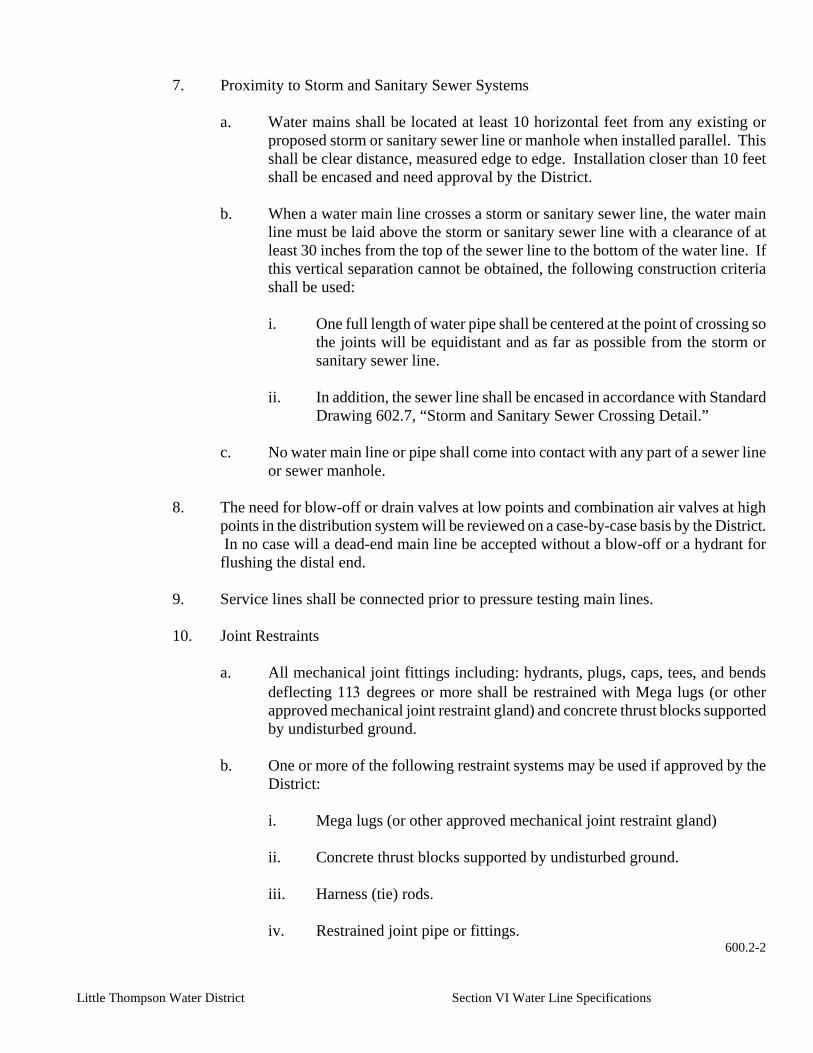
Little Thompson Water District Section VI Water Line Specifications
7. Proximity to Storm and Sanitary Sewer Systems
a. Water mains shall be located at least 10 horizontal feet from any existing or
proposed storm or sanitary sewer line or manhole when installed parallel. This shall be clear distance, measured edge to edge. Installation closer than 10 feet shall be encased and need approval by the District.
b. When a water main line crosses a storm or sanitary sewer line, the water main
line must be laid above the storm or sanitary sewer line with a clearance of at least 30 inches from the top of the sewer line to the bottom of the water line. If this vertical separation cannot be obtained, the following construction criteria shall be used:
i. One full length of water pipe shall be centered at the point of crossing so
the joints will be equidistant and as far as possible from the storm or sanitary sewer line.
ii. In addition, the sewer line shall be encased in accordance with Standard
Drawing 602.7, “Storm and Sanitary Sewer Crossing Detail.”
c. No water main line or pipe shall come into contact with any part of a sewer line or sewer manhole.
8. The need for blow-off or drain valves at low points and combination air valves at high
points in the distribution system will be reviewed on a case-by-case basis by the District. In no case will a dead-end main line be accepted without a blow-off or a hydrant for flushing the distal end.
9. Service lines shall be connected prior to pressure testing main lines.
10. Joint Restraints
a. All mechanical joint fittings including: hydrants, plugs, caps, tees, and bends
deflecting 113 degrees or more shall be restrained with Mega lugs (or other approved mechanical joint restraint gland) and concrete thrust blocks supported by undisturbed ground.
b. One or more of the following restraint systems may be used if approved by the
District:
i. Mega lugs (or other approved mechanical joint restraint gland)
ii. Concrete thrust blocks supported by undisturbed ground.
iii. Harness (tie) rods.
iv. Restrained joint pipe or fittings. 600.2-2

Little Thompson Water District Section VI Water Line Specifications
11. Surface water, railroad, highway, fiber optic or any other type of crossing, which may
require boring and casing must be reviewed with the Designated District Representative before final plans are prepared.
12. All bored and cased water lines shall be installed in accordance with Standard Drawing
602.6, “Standard Pipe Casing and Restraint Detail.”
C. Water Line Looping Policy
1. All main lines shall be “looped” when possible to minimize dead-ends.
2. Main line extensions, which are to be used, for fire protection and are dead-ended shall not be longer than 500 feet. Extensions longer than 500 feet may require over sizing and approval by the District.
3. The District may require looping on main lines longer than 500 feet.
4. Where dead-ends occur they shall be provided with a fire hydrant if flow and pressure
are sufficient, or with an approved flushing hydrant or blow-off for flushing purposes. a. No flushing device shall be directly connected to any sewer.
b. Flushing devices shall be installed at the distal end of all dead-end lines.
D. Water Line Over Sizing Policy
1. General
a. The purpose of this policy is to enable a Developer to install an oversized water
line with no additional expense to the Developer.
b. The “oversized” portion is the difference between a six (6) inch diameter main line (or larger if required) required by the main line extension or subdivision, and the diameter of water line which the District may need to meet future demands.
c. All over sizing and water development agreements shall be approved by the Board of Directors.
2. Summary of Policy
The over sizing policy shall apply to all water lines installed within the District boundary. This policy is applied in the following manner:
a. Determine the size (diameter) of water line to meet the overall District Master
Plan.
b. Develop an engineer’s estimate of the total cost for installing the required line and the oversized line.
600.2-3

Little Thompson Water District Section VI Water Line Specifications
c. Develop a chart to determine what portion of cost the District will participate in, and what portion of costs the Developer pays.
d. If the District participation is estimated to be $25,000 or less, then the Developer
may have the Contractor (approved by the District) install the line. The District will reimburse the Developer after construction is completed, based on the actual documented cost, but not to exceed $25,000.
e. If the District participation is estimated to be above $25,000, the District shall
participate in the project by one of three methods:
i. Material Provided
At the District’s option, the participation to the over sizing project would be through District provision of an amount of water line, or water line and other materials, equal in value to the District’s calculated financial commitment to the project. The Developer would specify the materials per District requirements and specifications. The District will advertise, bid and provide the materials specified.
ii. Developer Owned / Public Bid Project
At the District’s option, the project may be built by the Developer. After a public bid for the work, the District will determine the outcome of the bid based on the best interest of the District (Refer to Appendix “Construction Bidding for Public Projects Act”).
iii. District Owned Project
At the District’s option, the complete construction project may be designed, advertised, bid and constructed as a District owned project. In this case, the Developer would design the project per District requirements and specifications. Once the Developer provides funds for his portion of the project, the District would have the project built as a District project.
f. All agreements between the District and Developer concerning each party’s
commitment to the project will be included in a Water Line Over Sizing Agreement.
3. Water Line Size
a. The Developer shall provide the District with complete conceptual subdivision
utility Construction Drawings.
b. The plans shall include all utility lines and proposed lots to be served by the District.
c. The District shall review plans provided by the Developer to determine if the
600.2-4

Little Thompson Water District Section VI Water Line Specifications
District will require over sizing of the water line(s).
4. Determining if Over Sizing Is Required
a. The actual size (diameter) of the water line required for a main line extension or
new development shall be determined by the Designated District Representative. Criteria to be used for this determination shall include, but shall not be limited to, the following:
i. District Master Plan requirements.
ii. Potential future demands to water distribution system, which surrounds
proposed development.
iii. Hydraulic design criteria of water system.
5. District Participation in Over Sizing Project
a. After review of the Construction Drawings, the District shall determine if an oversized line shall be funded in part with District funds.
b. The District shall use the factors listed below to determine if the District will
participate in project funding:
i. Funds available to the District.
ii. Proximity to existing facilities.
iii. Effect on existing services and hydraulic capacity to serve.
iv. Other factors which the Board of Directors deems necessary while reviewing a proposed subdivision or development.
6. Calculating District Participation
a. Amount of Participation
The amount of participation shall be determined by the Board of Directors.
b. Estimate of Project Cost
The Developer shall furnish an estimate of oversized line project costs. Costs for preparing such estimates are to be borne entirely by the Developer.
c. Should the District participation be approved by the District, the District shall
then prepare a Water Development Agreement, which shall include:
600.2-5

Little Thompson Water District Section VI Water Line Specifications
i. Distribution of project costs between the District and the Developer.
ii. Time Schedule or phasing plan(s) which the Developer agrees to comply
with.
iii. Method of District Participation: either by supplying materials, as a District-owned project, or as a Developer-owned project.
iv. Method of payment or security from Developer to District.
v. Reimbursement agreements between the District and future Developers
along oversized line. The Water Line Over Sizing Agreement shall be prepared by the District and approved by the Developer and District’s Board of Directors.
d. Material Provided Method
At the District’s option, the District commitment to an over sizing project may be through an amount of pipe, or pipe and other materials being provided to the Developer for construction of the oversized line.
i. Ordering and Delivery of Materials
The Developer shall notify the District a minimum of six (6) weeks prior to the date scheduled for beginning of installation, unless otherwise specified in the Water Line Over Sizing Agreement. Pipe and materials will be delivered by the pipe supplier to a location specified by the District.
ii. Warranty and Repair of Material
The Developer shall not be held liable due to failure of material provided by the District, except in cases where material failure was found by the District to be a result of improper material handling or installation methods or procedures.
iii. Inspection
All construction of oversized line shall be inspected during installation by the District (or duly authorized Representative) in accordance with the design specifications and all applicable specifications contained herein.
e. Developer Owner/Public Bid Project Method
At the District’s option, the District commitment to an over sizing project may be by designing, bidding and constructing the project as a Developer owned and funded project.
600.2-6

Little Thompson Water District Section VI Water Line Specifications
i. Preparation of Design and Contract Documents
aa. The District shall require a Developer to pay all costs associated
with the design and preparation of contract documents for the project, subject to District approval.
bb. After contract documents are prepared, the Developer shall
advertise for and receive bids for the project. Bids shall be advertised in the name of the Developer. Bidding shall conform to requirements for public Bids. (Refer to Appendix “Construction Bidding for Public Projects Act”)
ii. Administration of Contract
aa. Actual administration of a construction contract shall be by the
Developer.
bb. Periodic payments during construction of an oversized line will be from the Developer to the Contractor and from the District to the Developer.
cc. All construction of oversized line shall be inspected during
installation by the District (or duly authorized Representative) in accordance with the design specifications and all applicable specifications contained herein.
f. District Bid and Owned Project Method
At the District’s option, the District commitment to an over sizing project may be by designing, bidding and constructing the project completely as a District owned and funded project.
i. Preparation of Design and Contract Documents
aa. The District shall require a Developer to pay all costs associated
with the design and preparation of contract documents for the project, subject to District approval.
bb. After contract documents are prepared, the District shall
advertise for and receive bids for the project. Bids shall be advertised in the name of Little Thompson Water District. Prior to contract award, the Developer shall, confirming to all terms set forth in the Water Line Over Sizing Agreement, forward to the District his financial commitment to project.
cc. The District reserves the right to reject all bids.
ii. Administration of Contract
600.2-7

Little Thompson Water District Section VI Water Line Specifications
aa. Actual administration of a construction contract shall be by the
Little Thompson Water District or its duly authorized Representative.
bb. Periodic payments during construction of an oversized line will
be from the District to the Contractor.
cc. All construction of oversized line shall be inspected during installation by the District (or duly authorized Representative) in accordance with the design specifications and all applicable specifications contained herein.
E. Operating Pressures
1. All main lines, service lines and appurtenances for the District must be designed for a
minimum static water pressure of 150 pounds per square inch (psi).
2. As determined by the Designated District Representative, some main lines, service lines and appurtenances for the District must be designed for a minimum static water pressure of 200 pounds per square inch (psi) or more.
3. The distribution system shall be designed to maintain a minimum of 45 pounds per
square inch (psi) at each service connection under normal operating conditions.
4. If normal operating pressure in the distribution system exceeds 45 pounds per square inch (psi), a pressure reducing valve may be installed ahead of each service meter to regulate customer service pressure at the meter pit to between 45 pounds per square inch (psi) and 55 pounds per square inch (psi).
5. The need for main line pressure reducing valves within the distribution system shall be
determined on a case-by-case basis by the District.
F. Pressure Reducing Stations
1. Pressure reducing valve (PRV) installations are used to control pressures within the District’s distribution system.
2. When Construction Drawings for main line extensions or developments are submitted
for review, the need for a PRV installation will be determined by the Designated District Representative based on existing pressure zones and the existing distribution system layout.
3. The District will provide direction and information for pressures, location and sizing of
all PRV installations.
4. PRV Operation Information to be included on the Construction Drawings:
a. Elevation 600.2-8

Little Thompson Water District Section VI Water Line Specifications
b. Upstream and downstream hydraulic grade line
c. Upstream and downstream pressure (pounds per square inch (psi)
5. PRVs connected to the District’s distribution system shall be owned, maintained and
operated by the District.
6. New PRV installations may require monitoring of the PRV via a supervisory control and data acquisition (SCADA) system. The equipment used shall be as specified in Section 600.2 L.
G. Storage Facilities
1. District Facilities
a. The need for storage facilities shall be evaluated on a case-by-case basis by the
Designated District Representative.
b. District storage facilities shall be located and sized in accordance with the District Master Plan.
c. New facilities shall be designed in accordance with written guidelines provided
by the Designated District Representative.
d. All new District storage facilities shall be monitored by the District SCADA system.
e. Non District water storage facilities may be allowed for storing water from the
District’s system where specifically authorized by the District and shall be of the type best suited for the particular installation.
f. Cleaning and Drainage
i. All storage facilities shall have built-in provisions for draining as well as
access and provisions for cleaning including a suitable source of water.
ii. The cleaning and draining facilities shall be subject to the approval of the District.
g. SCADA
i. As directed by the Designated District Representative, new storage
facilities may require monitoring via SCADA system.
ii. The equipment used shall be of the manufacturer and type specified in Section 600.2, Part L.
H. Pumping Facilities
600.2-9

Little Thompson Water District Section VI Water Line Specifications
1. District Facilities
a. The need for District pumping facilities shall be evaluated on a case-by-case
basis.
b. District pumping facilities shall be located and sized in accordance with the District Master Plan.
c. New facilities shall be designed in accordance with written guidelines provided
by the Designated District Representative.
d. All new District pumping facilities shall be monitored by the District SCADA system.
e. SCADA
i. As directed by the Designated District Representative, new pumping
facilities shall require monitoring via SCADA system.
ii. The equipment used shall be of the manufacturer and type specified in Section 600.2, Part L.
2. Non District Facilities
a. Pumping facilities will be allowed on services only where specifically
authorized by the District.
b. The District will prohibit the installation of pumping facilities where, such installations may be detrimental to the operation, or future operation, of the District’s distribution system.
c. All plans and specifications for pumping facilities shall be approved by the
Designated District Representative.
d. All material, equipment, and construction shall conform to all applicable or specified codes and standards and shall be approved by the District.
e. SCADA
i. As directed by the Designated District Representative, new pumping
facilities shall require monitoring via SCADA system.
ii. The equipment used shall be of the manufacturer and type specified in Section 600.2, Part L.
I. Valves
1. Locations
600.2-10

Little Thompson Water District Section VI Water Line Specifications
a. At all connections to the existing distribution system, new valves shall be
installed to isolate the new water line from the existing main line.
b. An in-line valve shall be installed at a minimum every 2,600 feet along a main line extension.
c. Valves shall also be installed at the following locations:
i. Between a fire hydrant and main line.
aa. One (1) valve shall be installed at the tee or tap on the main line
and a second valve shall be installed within 10 feet of the fire hydrant, on the branch of a tee to the hydrant or restrain the fire line between the valve and fire hydrant.
ii. River and Ditch Crossings
aa. All river or stream crossings with year-round flow shall have a
valve installed on each side of the waterway above the high water line.
bb. The Designated District Representative may require valves to be
installed on each side of an irrigation ditch crossing or intermittent stream.
iii. Between a blow-off and main line.
aa. Blow-offs at the end of a line which may be extended in the future or installed at low points along the main line shall be installed with a two (2) inch tap saddle and corporation stop.
iv. Vaults
aa. Valves to isolate flow through the vault shall be installed outside
and inside of the vault on the upstream and downstream side of each vault.
v. A minimum of two (2) valves shall be installed as shown on the
Construction Drawings or as directed by the Designated District Representative at all tees.
vi. A minimum of three (3) valves shall be installed as shown on the
Construction Drawings or as directed by the District at all crosses.
600.2-11

Little Thompson Water District Section VI Water Line Specifications
2. Type of Valves
a. General
i. All valves shall be open left.
ii. All valves shall have a two (2) inch square an operating nut.
iii. All valves shall be as specified in Section 601.3, “Valves,” of these
Water Line Specifications.
b. Gate Valves
i. Gate valves shall be installed on all water lines larger than two (2) inches in diameter unless otherwise specified on the Construction Drawings.
ii. All gate valves shall be resilient seated wedge type, epoxy coated inside
and out, with stainless steel bolts.
iii. Gate valves may be used on two (2) inch water lines with District approval.
c. Butterfly Valves
i. Butterfly valves shall be installed on water lines when specified on the
Construction Drawings.
ii. All butterfly valves shall be of the short body pattern and constructed of cast iron or ductile iron.
d. Ball Valves
i. Ball valves shall be installed on all water lines two (2) inches in diameter
and smaller, unless otherwise specified on the Construction Drawings.
ii. All ball valves shall be all bronze, full port ball valves, with a two (2) inch square operating nut.
iii. Gate valves may be used on two (2) inch water lines with District
approval.
J. Connections to Transmission Lines
1. All connections to transmission lines owned wholly or partially by the District shall be designed by the District unless otherwise authorized by the Designated District Representative.
600.2-12

Little Thompson Water District Section VI Water Line Specifications
2. All connections to transmission lines shall be conducted under the direct supervision of the Designated District Representative.
3. All District water lines larger than 12 inches in diameter are considered to be
transmission lines.
K. Interconnections to Other Water Systems 1. Temporary Hose Connections
a. Where conditions require the use of a temporary connection between a fire
hydrant and any device to collect, store or distribute water, the connection shall be made through a fire hydrant meter and backflow prevention device.
b. The District shall provide the fire hydrant meter, backflow prevention device
and instructions for operation.
c. The District shall charge for the use of the fire hydrant meter and for the water used. See Appendix, “Schedule of District Fees.”
2. Permanent Emergency Connections
a. Interconnections with other potable water systems to provide emergency service,
either from the District to the other entity or vice versa, shall be located and designed on a case-by-case basis.
b. A written agreement between the District and other potable water system must
be signed before the connection is installed.
c. Single Feed System Interconnection
i. From the District system, the flow shall go through a strainer, meter, PRV and a backflow prevention device as specified by the District.
ii. Valves shall be provided to shut off flow on either side of the master
meter.
iii. There shall be no bypass of the meter constructed.
d. Dual Feed System Interconnection
i. From the District system, the flow in and out shall go through a strainer, meter, PRV and a backflow prevention device as specified by the District.
600.2-13

Little Thompson Water District Section VI Water Line Specifications
ii. Valves shall be provided to shut off flow on either side of each of the
master meters.
iii. There shall be no bypass of the meters constructed.
e. Meters in the emergency connection vaults shall be read by the District on a monthly basis.
3. Permanent Master Meter Connections
a. From the District system, the flow shall go through a tee for the bypass, a
strainer, meter, PRV and a backflow prevention device as specified by the District.
b. Flow through the bypass shall go through a strainer, meter, PRV and a backflow
prevention device as specified by the District.
c. Valves shall be provided inside and outside of the vault to shut off flow on either side of the master meter or the bypass meter.
d. Master meters shall be read by the District on a monthly basis.
L. SCADA System
1. General
a. When specified on the Construction Drawings or in the Project Manual, a
SCADA system shall be installed in the vault with the new water line appurtenances.
b. The SCADA system shall be composed of equipment and instruments specified
by the Designated District Representative.
c. The SCADA system is part of the requirement to be installed with PRV vaults, pump stations, tanks and master meters.
2. Equipment and Instruments
a. General
i. The remote terminal unit (RTU) shall be an intelligent, modular unit
capable of both data acquisition and local data processing. It shall be able to monitor and control local equipment in a stand alone mode as well as being an intelligent node in a distributed processing system. It must be microprocessor based to allow reconfiguration and optimization
600.2-14

Little Thompson Water District Section VI Water Line Specifications
to occur via software only. Input/Output (I/O) modules shall be
connected to a basic processor module by plugging them into a motherboard on the RTU rack to facilitate changes and future expansions.
ii. A personal computer shall be used for program development and for
download either directly to the RTU or through the systems communication channel(s). Each RTU’s database may be merged into a single Central System database to automate the definition of the Central.
iii. The RTU must be supplied with the number and type of I/O points as
indicated elsewhere in the plans and specifications. Future expansion may be made by simply plugging in additional I/O modules to the I/O bus on the mother board. Each RTU must be supplied with the following configuration:
aa. Mother Board bb. I/O Bus cc. Enclosure dd. CPU Processor Module ee. Power Supply ff. Battery gg. I/O Modules as required hh. Communications Interface
iv. Communications
aa. General
The RTU shall support a variety of communication media and data transmission speeds. It must be a true multi-port device and be able to concurrently communicate with hierarchies above it (multiple centrals), with hierarchies parallel to it (RTU to RTU) and hierarchies below it (master/slave RTU’s). The RTU shall be able to communicate over up to three (3) mediums simultaneously or any combination thereof: on Port 1 via RS-232 or RS-485; on Port 2 via RS-232, or external modem, or protocol analyzers; on Port 3 via DFM or FSK radio.
bb. Data Protocol
i. The data communications shall utilize a secure, smart
protocol and have the following minimum features:
- Packet oriented with high efficiency variable length messages.
- Adhere to the seven layer ISO/OSI reference model for open systems interconnection.
600.2-15

Little Thompson Water District Section VI Water Line Specifications
- Able to transfer complete programs and historical data from RTU to central or between any points in the system.
- Support very high data security techniques, frame synchronization, dynamically assigned CRC codes (16/32 bit).
ii. The protocol shall allow high speed, efficient
communications for transmission of programs, databases and parameters. Complete configuration or diagnostic programs shall be transferable from/to the Central site or from RTU to RTU. This shall allow complete RTU/system debugging without visiting each remote site.
iii. This fully distributed protocol shall allow for the most
complex hierarchical system structures of multiple host computers and sub-master stations. Its complex structure shall be completely transparent to the system operator or engineer
cc. Communications Format
In addition to the traditional, simplistic master/slave polling configuration, the RTU shall operate in a number of more efficient contention formats. The RTU must be able to initiate data transmissions under these conditions:
i. Report by Exception: Automatically transmit upon
defined status change.
ii. Delta Limit Windows: Automatically transmit analog data when value differs from the last transmitted value by a defined percentage.
iii. Timed Transmission: Automatically transmit data on a
programmed time interval.
dd. Special Communication Requirements
In addition to the above described communication configurations, the RTU must also be able to support the following special modes.
i. Shared Transceiver Mode: Each RTU must be able to
share its communications transceiver (radio, wireline, etc.) with other RTU’s. Store and Forward Repeater: each RTU shall be able to receive information from other
600.2-16

Little Thompson Water District Section VI Water Line Specifications
sites, store it in memory, and then transmit (relay) it to another site.
ii. Network Interface Node: Each RTU shall be able to
function as an interconnection point between different communication systems, e.g., radio to line, between different radio frequencies, etc.
iii. Trunked Radio Interface: Each RTU shall be able to be
used in a trunked radio communication system. .
iv. Broadcast (Set Call): Any change in RTU or system data (i.e., time synchronization, mode switching, etc.) may be automatically transmitted to a set of locations, where the sets defined may have any number of qualifications.
ee. Radio Communication Channels
The RTU shall be able to operate on all two-way radio frequencies, namely VHF (136-174 MHz), UHF (402-430 and 450-470 MHz), 900 MHz Multiple Address, 800 and 900 MHz trunking, and microwave. The RTU must monitor the communication channel(s) to prevent transmission during a busy period. The RTU will support the following characteristics:
Transmission Mode: Half or full duplex Conventional Radio: Up to 4800 baud, Direct FM Trunked Radio: Up to 1800 baud
. ff. Wireline Communication Channels
The RTU shall be able to support operation over a traditional two-wire voice grade phone line with the following characteristics:
Transmission Mode: Half or full duplex Baud rate: 1200/2400 dependent upon line
quality Output impedance: 600 ohm or high impedance,
balanced Input signal level: 0 Dbm to -30 Dbm
. b. RTU Hardware Modules
i. Basic Processor Module
aa. The basic processor module (CPU) of the RTU shall be a real time process controller and support the following functions:
600.2-17

Little Thompson Water District Section VI Water Line Specifications
Bus communication with I/O modules System memory allocation Communication port control System parameter/logic programming
bb. The Central Processing Unit (CPU) of the module shall be a high
speed (>16MHz clock rate) 32 bit CMOS microprocessor, Motorola 68302 or equivalent. This VLSI design must incorporate a separate coprocessor (embedded RISC chip) to handle all external communication tasks so as to not affect base CPU performance functions.
cc. It shall be equipped with a minimum of 256 Kbytes onboard
memory of three different types.
EPROM for system program RAM for data and parameters EEROM for an application program
dd. Memory expansion must be allowable to a minimum of 2.5
Mbytes. Provision must be available to add a numerical coprocessor (Motorola 68882) with true double precision floating point capabilities along with additional memory and support for trigonometric and transcendental functions.
ee. The CPU module must incorporate a real-time clock (RTC) with
battery backup for both RTC and module RAM. Large scale CMOS gate array technology shall be used for minimum component count along with maximum performance and reliability. CPU features include:
I/O bus support. Diagnostic LED indication. Watch-dog timer (WDT). Symbolic debugging support. Power monitor for clean program start/stop.
ff. The RTU shall possess a minimum of three built-in
communication ports with the following characteristics:
Port 1: RS-232 or 485, software controlled. RS-232 with full DCE/DTE operation - to 9600 baud. RS-485 with UART operation - to 9600 baud.
Port 2: RS-232, full DCE/DTE, 9600 baud, transient protected
Port 3: Plug-In communication module for radio, wireline, trunked radio, dial-up wire line; 600-4800 baud.
600.2-18

Little Thompson Water District Section VI Water Line Specifications
gg. An additional communication module shall be available to
support an additional serial channel and second radio or wireline port.
I. Input/Output Modules
aa. General
i. The RTU shall be capable of addressing a highly variable
I/O count by the addition of expansion modules. Each module shall communicate with the CPU module via a high speed (> 1 Mbaud) data bus. Up to 240 modules shall be supported by a single CPU module; a dual CPU configuration shall be available but not provided. Each module may be plugged into any empty slot on the I/O bus.
ii. All modules, regardless of type must share some
common features including:
Input Protection: minimum on board dc/dc converter with 2.5 kv optical isolation according to IEEE SWC 472/585.
Output Protection: minimum 1 kv between contacts, 1.5 kv between contact and coil according to IEEE SWC 472/585.
Diagnostics: Loop back test, system clock, WDT, LED indicators of status and module failure modes.
Terminal Boards: Removable Phoenix type up to 14 AWG.
Module Identification: Check hardware versus application.
bb. Digital Input Module
i. Capacity
16 dry contacts, isolated inputs; 2 isolated high speed counters (up to 10 kHz).
ii. Counters
All base inputs may be defined as low speed counters (50-500 Hz).
iii. Input Filtering
600.2-19

Little Thompson Water District Section VI Water Line Specifications
Software control of hardware, 1-32 ms Interrupt Handling; Change of State (COS) reporting.
cc. Digital Output Modules
i. Type 1 -- Capacity: 16 electrically-energized relay
contacts (12 Form A, 4 Form C). Type 2 -- Capacity: 8 electrically-energized relay contacts (8 Form C).
ii. Both shall have a local, internal read back of auxiliary
relay contact for positive indication of output command execution.
dd. Analog Input Modules
Capacity: 8 floating inputs. Type: 4-20 ma, or 0-5 V, or +/-1 ma, or +/-1 V. Resolution: 13 bits including sign. Accuracy: +/- 0.05 %.
ee. Analog Output Module
Capacity: 4 optically isolated outputs. Type: 0-5 V or 4-20 ma, performance varies per power
supply. Resolution: 12 bits including sign. Accuracy: +/- 0.05%.
ff. Mixed I/O Module
Capacity: 8 isolated digital inputs.
Four (4) electrically-energized relay contacts (3 Form A, 1 Form C).
Analog inputs (10 bits).
c. RTU Software
i. Operating System
The software shall be based upon a Motorola Multi-Tasking Executive system, or equivalent, optimized for real-time environments.
ii. Application Software
aa. The RTU shall be programmed with a high level, multitasking ladder
diagram language which includes Boolean and arithmetic functions as well as specialized functions such as proportional control. These ladder diagrams shall be used for process
600.2-20

Little Thompson Water District Section VI Water Line Specifications
definitions as well as symbolic monitoring and debugging.
bb. The RTU application shall be defined using a stand alone programming package (Toolbox: Refer to item 4) on a MS-DOS computer.
d. RTU Programming Software (Toolbox)
i. General
aa. The RTU Programming Software (Toolbox) is a package of
computer programs that run on an IBM personal computer (PS/2 model 50 or later models, IBM AT or COMPAQ Laptop computers), enabling the system user to define and maintain the RTU system in accordance with user requirements without interrupting the real-time operation of the system or the RTU. This package shall develop and download the database and process, plus provide source level debugging of the application program. The programmer’s terminal shall be connected either locally via the RS-232 port to the RTU or remotely from any site in the system through the designated system communication channel
bb. The RTU configuration software shall be designed so that it will
automatically create all software entities needed to support the different hardware modules and communication ports as configured by the system engineer.
cc. After the RTU database is built, the communications, monitoring
and control processes are defined. These may be simultaneous (up to 8 processes can run independently) or sequential and may contain sub-processes to be performed dynamically. These sub-processes may include auto fail over to a backup communication channel(s), alternative control programs, etc.
dd. The application development package shall be able to download
the modified application to the RTU and allow real-time monitoring of the process. Ability to Force, Jump, or Skip to must be supported so that the user may view/change the actual values in the target system during program execution.
ii. Capabilities
aa. Programming the RTU application including definition of the
RTU configuration, system configuration, and RTU application (database and process).
bb. Downloading/uploading to/from the RTU the full or partial
600.2-21

Little Thompson Water District Section VI Water Line Specifications
database, via a local connection or the communication channel.
cc. On-line monitoring of the RTU operations.
dd. Performing remote software diagnostics. This program shall enable diagnostics of the RTU’s system software, by requesting diagnostics of each software module (object) by its logical name.
ee. Performing hardware tests and calibrations. Allows the
technician to verify the proper functioning of the I/O modules.
ff. Performing debugging of the application program in the RTU. The debugging tool uses a protocol analyzer program that is used to monitor the communication process, and enables selective display of sessions and protocol cross-sections that interest the software user. Each CPU can be configured to serve as a protocol analyzer interface between the link, which is intended to be checked, and the computer.
gg. Creating automatically a “central file” to be used later during
RTU database creation in the central. This definition shall be done in a tabular form in which the database is defined as a set of tables, where each table defines a group of devices; each row signifies a separate device and each column contains specific device data. The table entries are to be assigned user-significant names such as PUMP 1. Table values are to contain easily understood data such as equipment run time or number of pump starts.
e. Packaging
i. Construction
aa. The RTU shall be completely modular in design and
construction, allowing a specific configuration by merely plugging in the appropriate CPU and I/O modules. All modules and their assembly shall be accomplished without screws or fasteners of any type. All connections shall utilize a “snap-in” action.
bb. All components shall be completely solid state making extensive
use of CMOS and LSI circuitry. No jumpers, DIP switches, or adjustable potentiometers shall be allowed.
cc. Front access to all controls, indicators, RAM battery and external
connection cables shall be provided. Motherboard interconnection between I/O modules shall be direct; no daisy chain or multiple ribbon cable connections will be allowed.
600.2-22

Little Thompson Water District Section VI Water Line Specifications
dd. I/O modules shall be equipped with a front cover door to serve as: latch release, wiring identification, and terminal board protection. Cable ducts shall be used to direct and protect external wires from outside the RTU that are connected to the I/O modules.
ii. Enclosures
The RTU shall be available in a variety of wall mounted NEMA standard painted-steel housings of category 2, 4, 12 and 13. A NEMA 4 housing shall be available in a corrosion resistant baked epoxy finish. Stainless Steel and Fiberglass housings, and an industry standard 19 inch rack mounting assembly, shall also be available.
iii. Environmental
aa. The RTU shall operate over an ambient temperature range of -30
to +60C with relative humidity < 95%. It shall meet or exceed EIA standards’ RS-204B and RS-152B.
bb. The RTU shall meet or exceed the SWC standards as defined in
IEEE C37.90A for all inputs and outputs. In the appropriate enclosure, the RTU shall meet all qualifications for UL 611, paragraph 26.
iv. The RTU shall operate from 115/230 Vac, +/- 15%, 50/60 Hz primary
power. A battery and charging circuit shall be included to provide 4 hours standby operation (for defined RTU capacity). Larger capacity batteries shall be available to extend operating time.
3. Installation
a. The District shall coordinate with the District’s subcontractors to purchase and
install the SCADA equipment and instruments.
b. Installation of the SCADA system shall begin once the Contractor has completed his Work in the new vault.
c. The SCADA system may need to be operational before the new water line is put
into service and/or final acceptance of the Work.
M. Fire Protection
1. General
a. Fire protection requirements for water system design shall be provided by the agency or department having jurisdiction.
600.2-23

Little Thompson Water District Section VI Water Line Specifications
b. Fire hydrant and fire sprinkler branch lines shall be set at right angles to the
main lines.
c. The fire hydrant pumper nozzle shall face the street or road.
d. No horizontal or vertical bends or reducers shall be used in fire hydrant or fire sprinkler branch lines unless specifically approved by the District.
i. A gradelok mechanical joint grade adjustor or approved equal may be
used to raise fire hydrants to grade with approval of the District.
ii. A single fire hydrant extension may be used to raise the fire hydrant up to 18 inches to achieve a final grade. Extensions greater than 18 inches require approval by the District
e. Under no circumstances shall any size or manner of a tap be made on a fire
hydrant or fire sprinkler branch line.
f. A dead-end main shall have no more than one fire hydrant connected to it unless specifically approved by the Designated District Representative.
g. All fire hydrants shall be owned and maintained by the District.
h. Fire lines supplying sprinklers for residential or commercial use shall be
approved by the local fire protection district.
600.2-24

Little Thompson Water District Section VI Water Line Specifications
2. Fire Protection Agencies
Fire Protection Agency Contacts
Fire Protection District
Phone Number
Hydrant
Open Direction
Operating Nut
Berthoud Fire Protection District
(970) 532-2264
Right
Pentagon
Loveland Fire Department
(970) 962-2537
Right
Square
Longmont Fire Department
(303) 651-8439
Left
Pentagon
Mountain View Fire Protection District
(303) 535-4330
Left
Pentagon
Town of Milliken
(970) 587-4464
Left
Pentagon
Town of Johnstown
(970) 587-0339
Left
Pentagon
Hygiene
(303) 776-2950
Left
Pentagon
Poudre Fire
(970) 221-6570
Right
Square
Windsor
(970) 686-2626
Left
Pentagon
Platteville
(970) 785-2232
Left
Pentagon
Union Colony (Greeley)
(970) 350-9500
Right
Pentagon
No District Coverage
Right
Square
3. Location
a. New fire hydrants must be fed by a minimum six (6) inch supply line from two (2) directions or an eight (8) inch supply line for a dead end no longer than 500 feet.
b. All new fire hydrant installations shall be installed within dedicated easements
or public rights-of-way.
c. Hydrant spacing and location must be approved by the Fire Protection Agency having jurisdiction.
d. Local fire protection district or city codes apply.
4. Fire Hydrants
600.2-25

Little Thompson Water District Section VI Water Line Specifications
All fire hydrants installed within the District shall conform to Section 601.4, “Fire Hydrants and Blow-offs,” of these Water Line Specifications.
5. Fire Sprinkler Lines
a. An approved backflow prevention device must be installed on all water service
connections that supply a fire protection system.
b. All one (1) inch residential fire sprinkler taps shall be installed in accordance with Standard Drawing 602.14, “Residential 1” Fire Sprinkler Meter,” of these Water Line Specifications.
c. All other fire sprinkler lines shall be designed in accordance with the fire
protection district’s specifications and shall be approved by the District prior to installation.
N. Cross Connection Control
1. There shall be no physical connection between the distribution system or service lines of
the District to any other source of potable public or private water supplies without an approved backflow prevention device.
2. There shall be no physical connection with any non-potable water system.
3. There shall be no physical connection between the distribution system and any pipes,
pumps, hydrants or tanks whereby unsafe water or any other contaminating materials may be discharged or drawn into the District’s distribution system without the use of District approved backflow prevention devices.
4. The District’s Cross Connection Control Program is a separate document available from
the District.
O. Backflow Prevention Program
The District’s Backflow Prevention Program is a separate document available from the District.
~ End of Section ~
600.2-26

Little Thompson Water District Section VI Water Line Specifications
600.3 SERVICE LINES AND APPURTENANCES
A. General
1. Water is conveyed from mains to Tapholders by service lines and their appurtenances.
2. Service lines shall include all pipe and fittings up to and including the connection
point provided by the District.
3. All new or replacement service lines and appurtenant fittings installed within the District boundaries shall be installed in conformance with Section 601.7, “Service Connections,” of these Water Line Specifications.
B. Ownership and Maintenance
1. Ownership
a. The service line and all associated appurtenances from the main to the
connection point on the downstream side of the meter shall be installed and owned by the District.
b. The Tapholder shall install and own the water line from the connection point
outside of the meter pit to the point of use.
2. Maintenance
a. The service line and all associated appurtenances from the main to the connection point on the downstream side of the meter shall be maintained by the District.
b. The water line and all associated appurtenances from the connection point on
the downstream side of the meter to the point of use shall be maintained by the Tapholder.
c. The Tapholder shall keep the meter pit conveniently accessible from the
street side and clear of trees, shrubs, and bushes a minimum of three (3) feet around the meter pit.
C. Layout
1. Location
a. That portion of the service line between the main and the meter pit shall be in
a continuous straight line perpendicular to the main if possible.
600.3-1

Little Thompson Water District Section VI Water Line Specifications
b. The main to be tapped should extend a minimum distance of eight (8) feet
along the front or side lot line of the property to be served and the service line connection should be a minimum of five (5) feet into the lot.
c. Cul-de-sac
i. If service is requested for lots at the end of a cul-de-sac street, the
main to be tapped should not be more than 85 feet from any property line in the cul-de-sac.
ii. The service line between the main and the property line shall be in a
continuous straight line and shall enter the property a minimum distance of five (5) feet from the nearest lot corner.
d. Wye Services
i. Adjacent properties may share a portion of a service line in the
following manner:
aa. The joint service line between the main and the joint property line shall be in a continuous straight line perpendicular to the main, sized appropriately, and in line with the property line.
bb. Approximately five (5) feet outside of the property lines, a
wye shall be installed and individual service lines run to the point on the individual property lines five (5) feet from the joint property line.
cc. The service line shall then be run to the meter pit.
ii. See Standard Drawing 602.15, “Water Service Meter Pit Locations,”
of these Water Line Specifications.
2. Depth
a. All service lines shall be installed at a minimum depth of four (4.5) feet below finished grade.
b. Vertical grade adjustments between the main and meter pit shall be
completed as close to the main as is practicable.
c. If, the grade of the surface of the ground is changed on the Tapholder’s property, the Tapholder shall be responsible for maintaining a minimum of four (4.5) feet of cover on the service line.
3. Compaction
Backfill around the service line and a meter pit shall be carefully
600.3-2

Little Thompson Water District Section VI Water Line Specifications
compacted in accordance with Section 601.19, “Trenching, Backfilling and Compacting,” of these Water Line Specifications.
4. Length
a. That portion of the service line between the main and the meter pit shall not
exceed a horizontal length of 85 feet.
b. Longer service lines may be installed with the approval of the District and may require over sizing to minimize losses.
D. Separate Trenches
1. Service lines may not be installed in trenches containing conduits, which carry any
substance other than potable water.
2. A service line should be separated laterally from foreign conduits by a minimum of three (3) feet with ten (10) feet separation required for sewer lines.
E. Combination Service Lines
1. A property requiring a residential meter service and a residential fire sprinkler
service may be served from a single tap.
2. A one (1) inch residential fire sprinkler service shall be installed as shown in Standard Drawing 602.14, “Residential 1” Fire Sprinkler Meter,” of these Water Line Specifications.
3. An individual service connection may not be tapped into a fire sprinkler line.
F. Pumps
1. Pumping facilities will be allowed on services only where specifically authorized by
the District.
2. The District will prohibit the installation of pumping facilities where, such installations may be detrimental to the operation, or future operation, of the District’s distribution system.
3. All plans and specifications for pumping facilities shall be approved by the
Designated District Representative. 4. All material, equipment, and construction shall conform to all applicable or specified
codes and standards and shall be approved by the District.
G. Connections for Water
600.3-3

Little Thompson Water District Section VI Water Line Specifications
1. Residential taps, service lines and meter pits shall be installed by the Contractor if a
main line extension is required to provide service.
2. Service lines and taps for individual Tapholders on existing water lines shall be installed by the District or a Contractor as directed by the District.
3. Taps and fire line connections for individual Tapholders shall be installed by the
Contractor if a main line extension is required to provide service.
4. Taps and fire line connections for individual Tapholders shall be installed by the District or a Contractor as directed by the District.
5. The Tapholder is responsible for connecting the water line to the service line at the
connection point.
H. Taps, Saddles and Sleeves
1. Tapping saddles or sleeves shall be required for all taps on main lines.
2. No direct tapping of any main line materials shall be allowed without the approval of the Designated District Representative.
3. Tap saddles and sleeves shall be as specified in Section 601.5, “Tapping Saddles and
Sleeves,” of these Water Line Specifications.
I. Size
Taps and service lines shall be of a size, which is adequate to supply all the requirements of the property being served as determined by the Tapholder.
2. The recommended minimum sizes for service lines are shown in the table below.
Minimum Service Line Size
Water Line Length
Tap Size (inches)
< 85 feet
85 - 100 feet
> 100 feet
5/8”
3/4”
1”
3/4”
3/4”
1”
1”
1”
1 2”
1 2”
1 2”
2”
2”
2”
2”
Minimum 2”
600.3-4

Little Thompson Water District Section VI Water Line Specifications
J. Pipe Material
1. All of the service lines supplying water from the District’s system shall conform to
one of the following:
a. Seamless copper tube, designated as “Type K,” soft, may be used for service lines three quarter (3/4) inch to two (2) inches.
b. Polyethylene SDR 9, 200 pounds per square inch (psi) minimum pipe may be
used for service lines three quarter (3/4) inch to two (2) inches.
c. Ductile iron pipe may be used for service lines three (3) inches and larger.
d. PVC pipe may be used for service lines two (2) inches and larger.
K. Meters
1. All service meters shall be owned and maintained by the District.
2. All new service meters shall be installed with LTWD supplied meters.
3. All master meters are owned and maintained by the entity providing water service.
4. All new master meters shall be connected to the District’s SCADA system.
5. All new meters shall be as specified in Section 601.7, “Service Connections,” of these Water Line Specifications.
~ End of Section ~
600.3-5
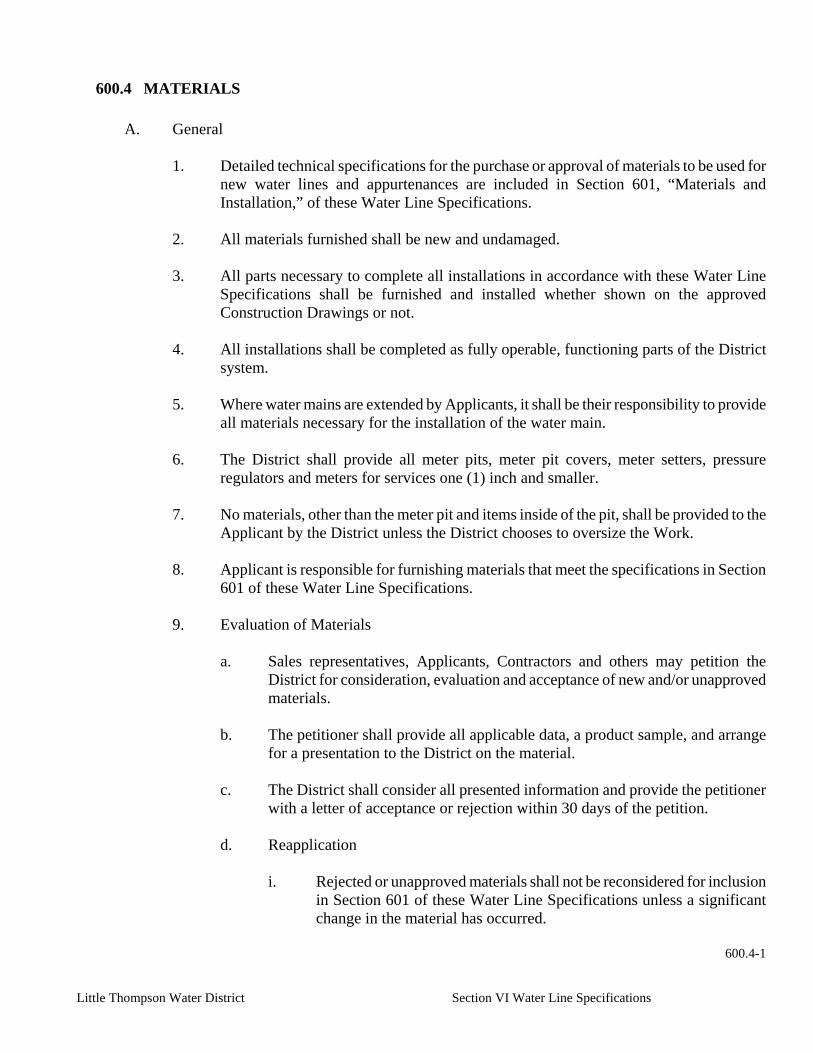
Little Thompson Water District Section VI Water Line Specifications
600.4 MATERIALS
A. General
1. Detailed technical specifications for the purchase or approval of materials to be used for new water lines and appurtenances are included in Section 601, “Materials and Installation,” of these Water Line Specifications.
2. All materials furnished shall be new and undamaged.
3. All parts necessary to complete all installations in accordance with these Water Line
Specifications shall be furnished and installed whether shown on the approved Construction Drawings or not.
4. All installations shall be completed as fully operable, functioning parts of the District
system.
5. Where water mains are extended by Applicants, it shall be their responsibility to provide all materials necessary for the installation of the water main.
6. The District shall provide all meter pits, meter pit covers, meter setters, pressure
regulators and meters for services one (1) inch and smaller.
7. No materials, other than the meter pit and items inside of the pit, shall be provided to the Applicant by the District unless the District chooses to oversize the Work.
8. Applicant is responsible for furnishing materials that meet the specifications in Section
601 of these Water Line Specifications.
9. Evaluation of Materials
a. Sales representatives, Applicants, Contractors and others may petition the District for consideration, evaluation and acceptance of new and/or unapproved materials.
b. The petitioner shall provide all applicable data, a product sample, and arrange
for a presentation to the District on the material.
c. The District shall consider all presented information and provide the petitioner with a letter of acceptance or rejection within 30 days of the petition.
d. Reapplication
i. Rejected or unapproved materials shall not be reconsidered for inclusion
in Section 601 of these Water Line Specifications unless a significant change in the material has occurred.
600.4-1

Little Thompson Water District Section VI Water Line Specifications
ii. In the absence of changed conditions, the material will not be
reconsidered for inclusion in Section 601 of these Water Line Specifications.
B. Pipe
1. Size of Mains
a. The size of water mains shall be in accordance with Section 600.2, Part A,
“Sizing Distribution Mains,” of these Water Line Specifications.
b. Standard acceptable nominal diameters of distribution mains covered by these Water Line Specifications shall be two (2), four (4), six (6), eight (8), 10, and 12 inches.
2. Size of Service Lines
a. Service line size shall be in accordance with Section 600.3, “Service Lines and
Appurtenances,” of these Water Line Specifications.
b. Standard acceptable nominal diameters of service lines covered by these Water Line Specifications shall be three quarter (3/4), one (1), one and one half (1 2), two (2), two and one half (2 2), and three (3) inches.
3. Pipe Class
a. Pipe class is a function of working pressures and water hammer surge pressures
and will be specified by the District depending on the location of the Work.
b. The following types of pipe with the minimum acceptable AWWA standard pressure ratings are the minimum that will be required by the District for two (2) inch through 12 inch diameter pipe.
i. Ductile Iron Pressure Rating 350 psi
ii. Plastic PVC DR 18 Pressure Class 150 psi
iii. Polyethylene (PE) SDR 9 Working Pressure 200 psi
4. Selection of Pipe
a. In general, selection of the type of pipe shall be left to the discretion of the
Design Engineer; however, the District reserves the right to deny or require the use of certain types of materials in specific circumstances.
b. Where joint restraint is required as described in these Water Line Specifications,
the Design Engineer shall select a pipe with an approved system of restraint.
600.4-2

Little Thompson Water District Section VI Water Line Specifications
c. Installation of any ductile iron pipe, fittings, rods, clamps, saddles, etc. will
require corrosion protection in the form of polyethylene wrap.
C. Pipe Fittings
1. Joints
a. All fittings shall be furnished with mechanical joint ends unless flanged or another restrained joint is specified on the Construction Drawings.
b. Fire hydrant tees shall have mechanical joint ends.
c. The use of wyes is prohibited.
d. A tee with a plug shall be used in place of a 90Ε bend unless specifically
approved by the Designated District Representative.
2. Closure Fittings
a. Bolted sleeve type couplings shall be of a gasketed, sleeve-type designed to properly fit the pipe.
b. Tolerance on pipe and coupling, together with proper bolt and gasket
arrangements, shall be sufficient to insure permanent watertight joints under all conditions.
c. Couplings shall be sufficiently wide, so that each type of pipe joined will have
as much pipe end inserted in the coupling as is provided by the standard push-on or mechanical joint for the pipe size and type involved.
d. Cast or ductile iron sleeves shall have mechanical joints of the proper size and
tolerance to assure a watertight fit.
3. Miscellaneous Pipe Fittings
a. Flanged adapters, plugs, end caps, bulkheads, cut-in sleeves, anchor couplings, repair fittings, and other appurtenances shall be used where appropriate and subject to approval of the District.
b. The District does not intend to unreasonably limit the installation of any type of
fitting, joint or proprietary device; however, the installation of any such material shall require the approval of the District prior to installation.
4. Clamps, Rods and Joint Restraint Devices
a. A mechanical joint restraint gland in combination with concrete thrust blocks is
the normal mechanical joint restraint system used on District water line installations.
600.4-3

Little Thompson Water District Section VI Water Line Specifications
b. Mechanical joint restraint glands, other than Mega lugs (Ebba Iron, Inc.), may
be approved by the District for use with or without concrete thrust blocks.
c. Proprietary joint restraint systems for pipe and fittings require the approval of the District prior to installation.
d. Harnessing of joints by harness rods must be approved by the District prior to
installation.
D. Valves
1. In-Line Valves
a. In-line valves 12 inches and smaller shall be gate valves as specified in Section 601.3, “Valves,” of these Water Line Specifications.
b. Butterfly valves and ball valves shall be installed when specified on the
Construction Drawings and shall be as specified in Section 601.3, “Valves,” of these Water Line Specifications.
c. The valves shall be of the same size as the main water line.
d. All valves shall have operators which open to the left (counterclockwise).
2. Pressure Regulating Valves
a. Pressure regulating valves (PRVs) shall conform to Section 601.3, “Valves,” of
these Water Line Specifications.
b. PRVs shall be sized so that the velocity through the valve at maximum demand does not exceed the manufacturer’s recommended velocity.
c. If a wide range of flow rates is anticipated, multiple PRVs in parallel may be
required to properly control the pressure across the anticipated range of flows.
d. Care shall be taken to ensure adequate pressure differential across the valve under all ranges of flow to accomplish hydraulic throttling.
e. PRVs shall be properly supported and have adequate clearance above and below
to facilitate servicing.
f. A regulated bypass may be required for PRV installations.
g. All new PRV installations require a SCADA system installation.
h. Each PRV shall have a valve on either side for isolation of the PRV and an outside valve on either side of the vault or manhole for isolation of the manhole or vault.
600.4-4
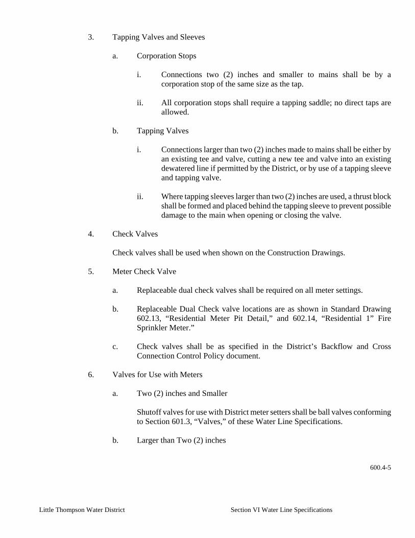
Little Thompson Water District Section VI Water Line Specifications
3. Tapping Valves and Sleeves
a. Corporation Stops
i. Connections two (2) inches and smaller to mains shall be by a
corporation stop of the same size as the tap.
ii. All corporation stops shall require a tapping saddle; no direct taps are allowed.
b. Tapping Valves
i. Connections larger than two (2) inches made to mains shall be either by
an existing tee and valve, cutting a new tee and valve into an existing dewatered line if permitted by the District, or by use of a tapping sleeve and tapping valve.
ii. Where tapping sleeves larger than two (2) inches are used, a thrust block
shall be formed and placed behind the tapping sleeve to prevent possible damage to the main when opening or closing the valve.
4. Check Valves
Check valves shall be used when shown on the Construction Drawings.
5. Meter Check Valve
a. Replaceable dual check valves shall be required on all meter settings.
b. Replaceable Dual Check valve locations are as shown in Standard Drawing
602.13, “Residential Meter Pit Detail,” and 602.14, “Residential 1” Fire Sprinkler Meter.”
c. Check valves shall be as specified in the District’s Backflow and Cross
Connection Control Policy document.
6. Valves for Use with Meters
a. Two (2) inches and Smaller
Shutoff valves for use with District meter setters shall be ball valves conforming to Section 601.3, “Valves,” of these Water Line Specifications.
b. Larger than Two (2) inches
600.4-5

Little Thompson Water District Section VI Water Line Specifications
i. Gate valves shall be resilient seated gate valves with cast iron or ductile
iron bodies conforming to Section 601.3, “Valves,” of these Water Line Specifications.
ii. All valves for use with meters shall be supported with adjustable valve
supports.
7. Corporation Stops
a. Uses
i. Corporation stops shall be used to provide the connection for a service line to the main without taking the main out of service.
ii. Corporation stops shall be used in combination air valve installations as
shown in Standard Drawings 602.9, “1” Air Vac Assembly,” and 602.10, “2” Air Vac Assembly.”
b. Sizes
Corporation stops are available in standard sizes of three quarter (3/4) inch, one (1) inch, one and one quarter (1 1/4) inch, one and one half (1 2) inch, and two (2) inch.
8. Curb Stops
a. Curb stops shall be used in fire sprinkler meter settings as shown in Standard
Drawing 602.14, “Residential 1” Fire Sprinkler Meter.”
b. Curb stops shall be used in combination air valve installations as shown in Standard Drawings 602.9, “1” Air Vac Assembly,” and 602.10, “2” Air Vac Assembly.”
9. Combination Air Valves
a. Combination air vacuum and air release valve installations shall be as shown in
Standard Drawings 602.9, “1” Air Vac Assembly,” and 602.10, “2” Air Vac Assembly.”
b. Combination air valves shall be installed at high points in the water line, where
there is an abrupt change of slope, at tie-in valves when the new water main slopes away from the valve, and where there is a need to protect the line from collapse due to a rapid loss of water.
c. Combination air valve locations shall be shown on the Construction Drawings.
600.4-6

Little Thompson Water District Section VI Water Line Specifications
10. Valve Boxes
a. All buried valves shall be provided with a six (6) inch cast iron screw type
adjustable valve box with a lid stamped “WATER.”
b. The valve box shall be designed to not transmit shock or stress to the valve and shall have enough extension capability to be raised to final street grade.
c. Valve boxes shall be installed as shown in Standard Drawing 602.8, “Valve Box
Detail.”
E. Control of Backflow and Cross Connection
1. Backflow Prevention
The District’s backflow prevention program is presented in a separate document. All specifications in that document apply to new water lines and appurtenances.
2. Cross Connection Control
The District’s cross connection control program is presented in a separate document. All specifications in that document apply to new water lines and appurtenances.
F. Marker Posts
The District shall install marker posts to identify all new valves or other underground appurtenances, as shown in Standard Drawing 602.18, “Tracer Wire Test Station.”
G. Meters
1. General
a. All meters installed for billing purposes shall be under the control of the District
and shall conform to these Water Line Specifications.
b. No meter shall be installed until the proposed installation has been approved by the District.
c. Meters used to record usage by the retail consumer are considered to be service
meters.
d. Meters used by wholesale customers and which supply water to other service meters are considered to be master meters.
e. Individual service meters shall be installed by the District.
600.4-7

Little Thompson Water District Section VI Water Line Specifications
f. Master meters may be installed by a Contractor and shall be inspected by the
District.
2. Size of Meter
a. Meters shall be of the same size as the corporation stop and tap at the main, unless specified otherwise by the Designated District Representative.
3. Type of Meter
a. The type of meter installed will be determined by the District at the time of
application.
b. All service meters and master meters shall conform to Section 601.7, “Service Connections,” of these Water Line Specifications.
c. Magnetic Drive Displacement Meter
Magnetic drive displacement service meters shall have a frost-proof bottom.
d. Compound Meter
Compound meters may be specified by the District if a large fluctuation in flow is anticipated.
e. Turbine Meter
i. Turbine meters may be specified for large flows where there is little
possibility of small flows below the manufacturer’s stated minimum flows.
ii. All turbine meters shall have an in-line strainer installed on the upstream
side of a design recommended by the manufacturers or approved by the District.
f. Electromagnetic Meters
i. Electromagnetic meters may be specified for large flows where there is
little possibility of small flows below the manufacturer’s stated minimum flows.
ii. All electromagnetic flow meters shall have an in-line strainer installed
on the upstream side of a design recommended by the manufacturers or approved by the District.
H. Meter Pits and Setters
1. Master Meters
600.4-8

Little Thompson Water District Section VI Water Line Specifications
All meters shall be installed in a horizontal position and housed in a concrete manhole or vault.
2. Service Meter Setters
a. All service meter setters shall be installed in a manner which will allow free
access and adequate room for inspection and maintenance and will protect the meter from freezing.
b. Service meter setters from five eighths (5/8) inch to one (1) inch shall be
installed in meter pits as shown in Standard Drawing 602.13, “Residential Meter Pit Detail.”
c. One and one half (1 2) inch and two (2) inch service meter setters shall be
installed in vaults as shown in Standard Drawing 602.19, “1 2 & 2” Meter Vault Detail.”
d. Service meters larger than two (2) inches shall be installed in vaults designed on
a case-by-case basis.
3. Radio Read System
All new service meters shall be equipped with the District’s radio read system.
4. Meter Bypass Lines
a. All master meters shall have a bypass line.
b. All new service meters shall not have a bypass line unless otherwise specified by the District.
5. Meter Couplings
All meter setters one and one half (1 2) inch and larger shall be installed with a coupling to allow removal of the meter without disturbing the pipe.
6. Meter Setter
a. A meter setter shall be provided by the District and installed by the Contractor
during the line extension or development.
b. A meter setter shall be installed by the District for individual service requests.
7. Valve and Meter Supports
a. Meter supports for one and one half (1 2) inch and larger meters shall be a solid concrete block or fabricated metal adjustable stands.
600.4-9

Little Thompson Water District Section VI Water Line Specifications
b. Adjustable fabricated metal stands shall be used to support valves four (4)
inches and larger.
8. Residential Meter Pits and Covers
a. All meter pits and covers shall be provided by the District.
i. For individual taps, the meter pits and covers shall be installed by the District.
ii. For main line extensions and developments, the meter pits and covers
shall be installed by the Contractor.
b. Meter pits shall consist of a plastic barrel, 20 inches in diameter and 36 inches long.
c. Meter pit covers shall consist of a cast iron meter pit cover, 12 inches high, with
a 12 inch diameter opening.
d. Meter pit lids shall have a double cover with an inner plastic lid and an outer cast iron cap-type lid held in place by a locking screw.
I. Vaults and Manholes
1. Vaults
a. Vaults may be precast or cast in place.
b. All vaults shall be designed so that all joints and corners are waterproof either by construction methods or after construction by the use of sealants.
c. The vault roof shall be designed to support the street fill and traffic loading in
accordance with AASHTO Standards.
d. Cast in place and precast vaults shall conform to Section 601.8, “Vaults and Manholes,” of these Water Line Specifications.
2. Manholes
a. Manholes shall be precast.
b. All manholes shall be designed so that all joints and corners are waterproof
either by construction methods or after construction by the use of sealants.
c. The manhole roof shall be designed to support the street fill and traffic loading in accordance with AASHTO Standards.
600.4-10

Little Thompson Water District Section VI Water Line Specifications
d. Precast manholes shall conform to Section 601.8, “Vaults and Manholes,” of
these Water Line Specifications.
3. Concrete
Concrete for vaults and manholes shall conform to Sections 601.13, “Cast In Place Concrete,” and 601.14, “Precast Concrete,” of these Water Line Specifications.
4. Sump Pits
a. Concrete vaults and manholes with concrete bases shall have sump pits.
b. The minimum pit opening shall be 12” x 12” square and open to gravel.
c. One & one half (12) inch diameter washed gravel shall be placed below the
sump pit in a minimum of two (2) feet wide by two (2) feet long by one (1) foot deep excavation.
d. Sump pits may have an automatic pump installed to adequately control the water
level in the vault with appropriate provisions made to handle the pump discharge.
5. Vent Pipes
a. Vent pipes shall be required on all vaults and manholes.
b. Vent pipes shall be field located to protect the vent pipe and minimize the
impact to the property.
c. All vent pipes shall have a screen on the outlet end of the vent pipe.
d. Vent pipe material shall be as specified on the Construction Drawings.
J. Fire Hydrants and Fire Lines
1. Fire Hydrants
a. Fire hydrant locations are normally specified by the local fire protection district (Refer to Section 600.2, “Distribution System Design and Layout,” Part M, of these Water Line Specifications).
b. The District reserves the right to require the installation of additional fire
hydrants at low points in the main line to serve as flush points for the District.
c. Fire hydrants shall be installed as close to the property line as is practical.
600.4-11

Little Thompson Water District Section VI Water Line Specifications
d. Fire hydrants shall be installed according to Standard Drawing 602.11, “Fire
Hydrant Assembly.”
2. Fire Lines
a. Fire line sizes and materials are normally specified by the local fire protection district.
b. Fire lines shall have a valve at the main line.
c. Fire lines shall have an approved backflow prevention device.
K. Service Lines
1. Service lines shall be of the size, which is adequate to supply the requirements of the
property being served.
2. The minimum service line size shall be three quarter (3/4) inch.
3. Service lines shall be type K seamless copper tubing, polyethylene tubing, PVC, or ductile iron pipe.
4. Service lines shall conform to Section 601.7, “Service Connections,” of these Water
Line Specifications.
L. Corrosion Protection Systems
1. All metallic pipe and fittings shall be protected against corrosion even when coated in epoxy or other material.
2. Polyethylene wrap shall be used on all ductile iron pipe, fittings, rods and
appurtenances.
3. Polyethylene wrap shall conform to Section 601.12, “Polyethylene Encasement,” of these Water Line Specifications and installed as specified in Standard Drawings 602.16, “Field Installation of Polyethylene,” of these Water Line Specifications.
M. Thrust Blocks
1. Concrete thrust blocks shall be sized for the internal static water pressure plus the
internal transient pressures, and for soil bearing capacity.
2. Standard shapes and sizes of concrete thrust blocks shall be as specified in Standard Drawings 602.3, “Horizontal Thrust Block Detail,” and 602.4, “Upper Vertical Thrust Block Detail,” of these Water Line Specifications.
3. Concrete for thrust blocks shall conform to Section 601.13,
600.4-12

Little Thompson Water District Section VI Water Line Specifications
“Cast In Place Concrete,” of these Water Line Specifications.
N. Casing Pipe
1. The installation of water mains across right-of-way or easements of others, such as
highways, roads, railroads, irrigation ditches, etc., may require the use of casing pipe for the bores.
4. The type of casing material and its properties shall be as specified in Section 601.9, “Pipe
Casing, Boring and Jacking,” of these Water Line Specifications unless otherwise specified by the agency granting permission to cross.
3. Casing installation methods shall be as specified in Section 601.9 and Standard Drawing
602.6, “Standard Pipe Casing Detail,” of these Water Line Specifications.
~ End of Section ~
600.4-13

Little Thompson Water District Section VI Water Line Specifications
600.5 EARTHWORK
A. Definition
Earthwork shall include all clearing, grubbing, grading, excavation, fill, backfill, excess excavation, bedding and pipe zone material, borrow material, and surface restoration that may be required to complete the Work.
B. Exploratory Excavation
All underground utilities and structures that may interfere with the Work shall be sufficiently located in advance to permit any necessary relocation without delays.
C. Alignment and Grade
1. All excavations shall be made to the alignment and grades as established by the
approved Construction Drawings.
2. Approval from the District is required for deviation from grades in excess of those specified in Section 601.18, “Pipe Installation,” of these Water Line Specifications.
D. Trenching Operations
1. Trench Width
Trench width shall be as specified in Section 601.19, “Trenching, Backfilling and Compacting,” of these Water Line Specifications.
2. Trench Support
a. The trench shall be adequately supported to ensure the safety of the workers.
b. Sheeting, shoring or other appropriate trench support shall be utilized to
prevent any excessive widening or sloughing of the trench which may be detrimental to human safety, to the pipe or appurtenances being installed, to existing utilities, to existing structures, or to any existing facility.
c. Excavated material shall not be placed closer than two (2) feet from the top
edge of the trench.
E. Excavation for Structures
Except as otherwise dictated by construction conditions, the excavation shall be of such dimensions as to allow for the proper installation and removal of concrete forms or precast concrete items and to permit the construction of all necessary pipe connections.
F. Surplus Excavation Material 600.5-1

Little Thompson Water District Section VI Water Line Specifications
All surplus excavation material shall be removed from the Job Site and disposed of properly and in a timely manner.
G. Blasting
1. Approved blasting shall take place as specified in Section 601.20, “Rock
Excavation,” of these Water Line Specifications.
2. The Contractor is responsible for obtaining all necessary permits, providing proper notice, and repairing any damage resulting from the blasting operations.
H. Dewatering
1. The Contractor is responsible for obtaining all necessary permits for dewatering
operations.
a. If groundwater will be discharged into an irrigation ditch, pond, stream or waterway, or will drain to an irrigation ditch, pond, stream or waterway, a Colorado Department of Public Health and Environment (CDPHE) dewatering permit will be required.
b. Dewatering permit applications may take up to 30 days to be reviewed by the
CDPHE.
c. The contractor is required to complete and process the Discharge Monitoring Report (DMR) that is typically a part of the dewatering permit.
d. Upon finishing the Work, the Contractor shall be responsible for completing
a Colorado Department of Health Termination Notice.
2. Water that is encountered in the trench shall be removed to the extent necessary to:
a. Provide a firm subgrade.
b. Permit connections to be made in dry conditions.
c. Prevent the entrance of water into the pipeline.
3. Surface runoff shall be diverted as necessary. Pumps, gravel blankets, well points, drain lines or other means may be used to keep excavations and trenches free from water during construction.
4. The excavation or trench shall be kept free from water until the structure or pipe to
be installed therein is completed to the extent that no damage from hydrostatic pressure, flotation, or other cause will result.
5. The pipe under construction shall not be used for dewatering.
600.5-2

Little Thompson Water District Section VI Water Line Specifications
I. Foundations on Unstable Soil
If the bottom of the excavation is soft or unstable, as determined by the Designated District Representative, and cannot satisfactorily support the pipe or structure, then a further depth and width shall be excavated a minimum of six (6) inches below grade and refilled with rock uniformly graded between three quarters (:) of an inch and one and one half (12) inches.
J. Pipe Bedding and Pipe Zone Material
Pipe bedding and pipe zone material shall be as specified in Section 601.19, “Trenching, Backfilling and Compacting,” of these Water Line Specifications.
K. Backfill and Compaction
Backfilling and compacting shall be performed as specified in Section 601.19, “Trenching, Backfilling and Compacting,” of these Water Line Specifications.
L. Flowable Concrete Backfill
1. Flowable concrete backfill shall be used when specified by a right-of-way granting
entity, the Construction Drawings, or when directed by the District.
2. Flowable concrete backfill shall be installed as specified in Section 601.15, “Flowable Concrete Backfill,” of these Water Line Specifications.
M. Clean Up
1. General
a. At all times during the Work, the Contractor shall keep the premises clean
and orderly, and upon completion of the Work, repair all damage caused by equipment and leave the project free of rubbish or excess materials of any kind.
b. The Contractor shall stockpile excavated materials in a manner that will
cause the least damage to adjacent lawns, grassed areas, gardens, shrubbery, or fences regardless of whether these are on private property, or on Town, State, or County rights-of-ways.
c. The Contractor shall remove all excavated materials from grassed and
planted areas, and leave these surfaces in a condition equivalent to their original condition.
d. The Contractor shall insure that all existing drainage ditches and culverts shall be reopened and graded and natural drainage restored.
e. The Contractor shall restore broken or damaged culverts and field drains to
their original condition and location. 600.5-3

Little Thompson Water District Section VI Water Line Specifications
f. Upon completion of pipe laying and backfilling operations, the Contractor shall rake or drag all former grassed and planted areas, leaving all disturbed areas free from rocks, gravel, clay or any other foreign material.
g. The Contractor shall insure that finished surface shall be free draining and
free from holes, ruts, rough spots, or other surface features detrimental to a seeded area.
2. Tree Removal
No trees, except those specifically shown on the Drawings to be removed, shall be removed without the approval of the Designated District Representative.
3. Finishing of Site, Borrow, and Storage Areas
a. Upon completion of the work, all areas used by the Contractor shall be
properly cleared of all temporary structures, rubbish and waste materials and properly graded to drain and blend in with the abutting property.
b. Areas used for the deposit of waste materials shall be finished to properly
drain and blend with the surrounding terrain.
4. Removal of Rock From Finished Surfaces
If requested by the Property Owner or specified by the District, remove and dispose of all loose rock and boulders occurring on the finished surfaces as a result of the construction operations.
5. Street Clean Up During Construction
Thoroughly clean all spilled dirt, gravel, or other foreign material caused by the construction operation from all streets and roads at the conclusion of each day’s operation.
6. Dust Prevention
Applicable environmental regulations for dust prevention shall be strictly followed.
N. Subgrade and Road Preparation
1. Prior to installation of water mains in dedicated streets, road construction and grading must have progressed to at least the subgrade stage.
2. The subgrade elevation is defined as an elevation, which lies no more than seven (7)
inches below the finished road grade.
3. The road surface shall be smooth, clear of debris and free from deep holes, ruts, and large rocks which may hamper water line installation.
600.5-4

Little Thompson Water District Section VI Water Line Specifications
4. Once the water line has been installed, the road surface shall be repaired to a
condition equal to that prior to construction.
O. Compaction
1. Compaction of the trench after installation of the water line shall be in accordance with Section 601.19, “Trenching, Backfilling and Compacting,” of these Water Line Specifications.
2. If the Work is located within a public right-of-way or private easement, compaction
shall meet the requirements of the agency or utility granting the permit.
3. If not otherwise specified, the minimum compaction shall be 95% in roads or right-of-way and 90% elsewhere.
P. Surface Restoration
1. Unsurfaced Areas
a. All unsurfaced cuts shall be, as a minimum, restored to a condition equal to
that prior to construction.
b. All roads shall be restored in accordance with the regulations and requirements of the agency having control or jurisdiction over the street, roadway, or right-of-way.
2. Surfaced Areas
a. All surface cuts shall be, as a minimum, restored to a condition equal to that
prior to construction.
b. All gravel or paved streets and roads shall be restored in accordance with the regulation and requirements of the agency having control or jurisdiction over the street, roadway or right-of-way.
c. Specifications for restoration of gravel surfaces, asphalt pavement, and
driveways and road crossings are provided in Section 601 of these Water Line Specifications.
3. Easements, Cultivated or Agricultural Areas
a. If specified in the easement conditions, topsoil to a depth of four (4) inches or as otherwise specified, shall be removed from the area of general disturbance and stockpiled.
b. After installation of all pipelines, appurtenances, and structures, and
completion of all backfill and compaction, the stockpiled topsoil shall be redistributed evenly over all disturbed areas.
600.5-5

Little Thompson Water District Section VI Water Line Specifications
c. Care should be taken to conform to the original ground contour or final
grading plans.
d. Areas requiring revegetation shall be prepared and seeded in accordance with Section 601.22, “Site Revegetation,” of these Water Line Specifications.
~ End of Section ~
600.5-6

Little Thompson Water District Section VI Water Line Specifications
600.6 WATER LINE DISINFECTION AND TESTING
A. Disinfection
1. General
a. The Contractor shall satisfactorily disinfect and test new water lines prior to the District placing them in service in accordance with AWWA Standard C651, “Disinfecting Water Mains.”
b. The District shall flush all new water lines prior to placing in service in
accordance with AWWA Standard C651.
c. Notice to the District for water line disinfection and testing shall be as specified in Section 600.1, Part F of these Water Line Specifications.
2. Materials
a. Hypochlorite
The disinfecting agent shall be a hypochlorite in an approved form as referenced in AWWA Standard B300, “Hypochlorites.”
b. Adhesive
Any adhesive used to attach hypochlorite tablets to the interior of the pipe, shall be a food grade adhesive, which has received US Federal Drug Administration approval for uses that may involve contact with edible products.
B. Filling Pipe
1. The District shall operate valves to fill the new water lines, open blow-offs, and
hydrants.
2. Where air vents are not available, the Contractor shall install corporation stops at high points in the water line in order to evacuate air.
3. All temporary corporation stops which were installed to facilitate evacuation of air from
the water main shall be removed and plugged after the water main is filled and prior to pressure testing.
C. Preliminary Flushing
1. The water line shall be flushed at a minimum velocity of two and one half (22)
feet/second in order to remove foreign material prior to disinfection.
2. Preliminary flushing shall not be performed if the tablet method of disinfection was used by the Contractor.
600.6-1
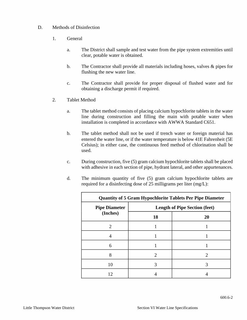
Little Thompson Water District Section VI Water Line Specifications
D. Methods of Disinfection
1. General
a. The District shall sample and test water from the pipe system extremities until clear, potable water is obtained.
b. The Contractor shall provide all materials including hoses, valves & pipes for
flushing the new water line.
c. The Contractor shall provide for proper disposal of flushed water and for obtaining a discharge permit if required.
2. Tablet Method
a. The tablet method consists of placing calcium hypochlorite tablets in the water
line during construction and filling the main with potable water when installation is completed in accordance with AWWA Standard C651.
b. The tablet method shall not be used if trench water or foreign material has
entered the water line, or if the water temperature is below 41Ε Fahrenheit (5Ε Celsius); in either case, the continuous feed method of chlorination shall be used.
c. During construction, five (5) gram calcium hypochlorite tablets shall be placed
with adhesive in each section of pipe, hydrant lateral, and other appurtenances. d. The minimum quantity of five (5) gram calcium hypochlorite tablets are
required for a disinfecting dose of 25 milligrams per liter (mg/L):
Quantity of 5 Gram Hypochlorite Tablets Per Pipe Diameter
Length of Pipe Section (feet)
Pipe Diameter
(Inches) 18
20
2
1
1
4
1
1
6
1
1
8
2
2
10
3
3
12
4
4
600.6-2

Little Thompson Water District Section VI Water Line Specifications
f. Tablets shall be attached with an approved adhesive and shall be placed on the
top of the interior of the pipe in such a manner that there is no adhesive on the tablet except on the broad side of the tablet next to the pipe surface.
g. Water shall be introduced into the pipe at a velocity no greater than one (1)
foot/second.
h. The chlorinated water shall be retained in the water lines for a minimum of 24 hours (unless the water temperature is less than 41Ε F and then the water shall be retained for at least 48 hours), during which time the treated water must contain no less than 25 mg/L of chlorine throughout the entire length of the water lines.
i. The chlorinated water shall be flushed by the District within five (5) days unless
otherwise approved by the District.
3. Continuous Feed Method
a. The continuous feed method of disinfecting water lines shall be accomplished in accordance with AWWA Standard C651.
b. The continuous feed method consists of completely filling the water lines to
remove all air pockets, flushing the completed lines to remove particulates, and filling the line with potable water chlorinated so that after a 24 hour holding period in the line, there will be a free chlorine residual of not less than 25 milligrams per liter.
c. Prior to being chlorinated, the water lines shall be filled to eliminate air pockets
and shall be flushed at a velocity not be less than two and one half (2 2) feet per second.
d. Chlorinated water supplied from a temporary, backflow-protected connection, shall
be introduced into the water line at a point approved by the District at a constant, measured rate so that the chlorine concentration is maintained at a minimum of 25 mg/L.
600.6-3

Little Thompson Water District Section VI Water Line Specifications
Chlorine Required to Produce 25 mg/L in 100 Feet of Pipe
Pipe Diameter (Inches)
100% Chlorine
(Pounds)
1% Chlorine Solution
(Gallons)
4
0.013
0.16
6
0.030
0.36
8
0.054
0.65
10
0.085
1.02
12
0.120
1.44
f. The chlorinated water shall be retained in the water lines for a minimum of 24 hours (unless the water temperature is less than 41ΕF and then the water shall be retained for at least 48 hours), during which the treated water in all portions of the main shall have a free residual of not less than 25 mg/L.
g. The chlorinated water shall be flushed by the District within five (5) days unless
otherwise approved by the District.
4. Slug Method
a. The slug method of disinfecting water lines shall be accomplished in accordance with AWWA Standard C651.
b. The slug method consists of completely filling the water lines to remove all air
pockets, flushing the completed lines to remove particulates, and slowly flowing through the main a slug of water dosed with chlorine to a concentration of 100 milligrams per liter.
c. The slow rate of flow ensures that all parts of the water lines and appurtenances
will be exposed to the highly chlorinated water for a period of not less than three (3) hours.
d. Prior to being chlorinated, the water lines shall be filled to eliminate air pockets
and shall be flushed at a velocity not less than two and one half (2 2) feet per second.
e. Chlorinated water supplied from a temporary, backflow-protected connection,
shall be introduced into the water line at a point approved by the District at a constant, measured rate so that the chlorine concentration of the slug is a minimum of 100 mg/L.
f. The chlorine concentration shall be monitored as it moves through the water
lines and appurtenances.
600.6-4

Little Thompson Water District Section VI Water Line Specifications
g. If at any time the free chlorine concentration in the slug drops below 50 mg/L,
the flow shall be stopped, the chlorination equipment moved to the head of the slug, and as flow is resumed, additional chlorine shall be applied to restore the feed chlorine concentration to not less than 100 mg/L.
5. Disinfection for Repair of Existing Water Lines
a. The interior of all pipe and fittings, particularly couplings and sleeves, used in
making the repair shall be swabbed with a minimum one percent (1%) hypochlorite solution before they are installed.
b. Thorough flushing is the most practicable means to remove contamination
introduced during repairs; however, slug chlorination with a slug concentration of 300 mg/L and a contact time of 15 minutes may be used if contamination is likely.
c. Bacteriological samples may be taken after the repairs are completed to ensure
the procedure’s effectiveness.
E. Final Flushing
1. After the applicable retention period, the chlorinated water shall be flushed from the water lines until the chlorine measurements show that the concentration in the water leaving the new lines is no higher than that generally prevailing in the system.
2. The Contractor shall be responsible for all necessary chlorine neutralization and/or
discharge permits and to ensure that no environmental damage occurs.
3. Reference Appendix B of AWWA Standard C651 for a list of neutralizing chemicals.
F. Bacteriological Testing
1. Prior to pressure testing or placing water lines in service, the District shall collect bacteriological samples from the water line after final flushing and a 24 hour rest period,.
2. The District shall collect bacteriological samples from each 2,500 feet of new water
main.
3. Acceptable bacteriological sample locations are: meter pits, fire hydrants, blow-offs (temporary or permanent), or a corporation stop installed with a temporary copper gooseneck assembly.
G. Repetition of Procedure
1. If the initial disinfection, or subsequent disinfections, fails to produce satisfactory
bacteriological samples, the water lines shall be reflushed and resampled.
600.6-5

Little Thompson Water District Section VI Water Line Specifications
2. If the bacteriological samples are still not satisfactory, the water lines shall be
rechlorinated by the continuous feed or the slug method of chlorination until satisfactory results are obtained.
H. Hydrostatic Testing
1. Description
a. Water services shall be tested together with the main water line.
b. Once the water line has been filled, flushed and confirmed to be disinfected by
negative bacteriological tests, and flushed, a hydrostatic test shall be conducted.
i. The contractor shall provide all equipment and personnel necessary to perform the hydrostatic test.
aa. Test equipment shall be able to maintain a continuous internal
pipe pressure of 150 pounds per square inch (psi) (or more if required by the District) and accurately measure leakage over a two (2) hour minimum test period.
bb. The maximum allowable pressure gauge increment shall be five
(5) pounds per square inch (psi).
cc. A water meter shall be used to measure the amount of water used in pressurizing the system.
ii. The District requires a minimum of 48 hours advance notice for all
hydrostatic testing.
iii. The District will record times, leakage readings, and pressure over the test period.
c. Hydrostatic testing shall not occur until at least three (3) days have elapsed since
the last concrete thrust block was cast, or until a minimum compressive strength of 2,500 pounds per square inch (psi) is achieved.
d. The hydrostatic pressure test shall be performed against all valves within the
new piping system, unless otherwise approved by the District.
2. Pressure Test
a. “Leakage” is the quantity of water that must be supplied into the newly laid
water line, or any valved section thereof, to maintain a pressure within five (5) pounds per square inch (psi) of the specified test pressure after the air has been expelled and the pipe has been filled with water.
600.6-6

Little Thompson Water District Section VI Water Line Specifications
b. Test Pressure
i. For ductile iron pipe and PVC pipe, the minimum test pressure shall be 150 pounds per square inch (psi).
ii. A pressure within five (5) pounds per square inch (psi) of the test
pressure shall be maintained for a minimum of two (2) hours.
c. Leakage Allowance Formula
The maximum allowable leakage for each test section of ductile iron pipe and PVC pipe is determined by the following formula:
__ L = SD √ P 133,200
L = maximum allowable leakage in gallons S = Length of pipe tested in feet D = nominal pipe diameter in inches P = average test pressure during the leakage test in pounds
per square inch (psi)
d. Leakage Allowance Chart
Hydrostatic Test Leakage Allowance (@ 150 psi)
Pipe Diameter
(Inches)
Allowable Loss per 1000 Feet
(Gallons)
2
0.631
4
1.263
6
1.894
8
2.525
10
3.157
12
3.788
600.6-7

Little Thompson Water District Section VI Water Line Specifications
e. Testing and Leakage
i. Unless prior approval is given by the District, a test section shall not be
any longer than the length of pipe between adjacent line valves.
ii. If the test leakage is greater than the allowable leakage, the defective materials and joints shall be located and repaired by the Contractor.
iii. The hydrostatic tests shall be repeated until the leakage is less than the
maximum allowable leakage.
iv. With the exception of obvious leaks, passing of the hydrostatic test shall be based on the maximum allowable leakage per section tested.
v. All visible leaks shall be repaired regardless of maximum allowable
leakage.
~ End of Section ~
600.6-8

Little Thompson Water District Section VI Water Line Specifications
600.7 CONNECTION TO EXISTING MAINS AND REPAIRS0
A. Connection to Existing Mains
1. Utility Verification
a. At locations where connections to existing water lines are to be installed, the Contractor shall locate the existing lines both vertically and horizontally and shall verify exact pipe diameter in advance of the time scheduled for making the connection.
b. At locations where connections to existing water lines are to be installed, the
Contractor shall locate all other utilities both vertically and horizontally to verify no utility conflicts in making the connection.
2. Notification
a. The Contractor shall notify and schedule the connection with the District, a
minimum of 72 hours in advance if a shut down of an existing water line is required or 24 hours in advance for a wet tap.
b. Any Tapholder affected by a planned shut down of an existing water line shall
be provided with 48 hours notice of the shut down. The notice shall detail when and how long the shut down will last.
3. Connection
a. Prior to connecting to existing water lines, the Contractor shall have all
personnel, material and equipment ready to connect the fittings to the existing lines to minimize the shut down time.
b. The Contractor shall take every precaution necessary to prevent trench water,
dirt or debris from entering the water lines during the connection.
c. As soon as possible after making the connection, the District shall flush the connection so as to prevent any contamination of the existing facilities.
4. Quality Control
a. Connections to the District’s water system shall be completed in a safe, neat and
orderly manner. (Ref. District Cross Connection & Backflow Prevention Policy 305.7).
b. A District Representative shall inspect all connections.
600.7-1

Little Thompson Water District Section VI Water Line Specifications
c. Under no circumstances shall a non-disinfected waterline, which cannot be
isolated, be connected to an existing disinfected waterline. (See separate document, “Cross Connection and Backflow Prevention Policy, 305.7”).
d. The District is not responsible for water tightness of its valves.
e. If existing valves leak, the District will assist in reducing the influx of water, but
the Contractor shall use methods at his own disposal to work with the resulting leakage.
5. Operation of Valves
Valves on the District’s system shall be operated only by District personnel.
B. Repair of Water Lines
1. Utility Verification
At the location where the repair or replacement Work is to be completed, the District or Contractor performing the Work shall obtain utility locates to determine which other utilities are in the area.
2. Emergency Repair
a. When an existing water line breaks or requires other repair or replacement, the
District or Contractor shall make every effort to complete the Work in a timely manner to restore water service to affected Tapholders.
b. The District or Contractor shall take every precaution necessary to prevent
trench water, dirt or debris from entering the water line during the repair. Precautions may include maintaining positive pressure in the water line, until the area around the break has been adequately prepared for repair.
c. As soon as possible after making the repair, the District shall flush the main so
as to prevent any contamination of the existing facilities.
d. Materials used for repairs shall be disinfected prior to installation. (Ref 600.6 (D) 5, “Disinfection for Repair of Existing Water Lines” of these Water Line Specifications.)
e. The repaired water line shall be flushed and tested by District personnel, and a
bacteriological sample shall be collected. (Ref 600.6 (D) 5)
3. Repair Methods
a. Repair bands, solid sleeves or couplings may be used.
600.7-2

Little Thompson Water District Section VI Water Line Specifications
b. No repair shall be closer than 18 inches from a bell, coupling, service
connection, or other repair.
c. No asbestos cement pipe shall installed during a repair
~ End of Section ~
~ END OF SECTION 600 ~
600.7-3

Little Thompson Water District Section VI Water Line Specifications
601 MATERIALS AND INSTALLATION
601.1 PVC PIPE
A. General
1. Description
This section addresses four (4) inch through 12 inch PVC pipe and includes the acceptable materials and construction practices which shall be used in the installation of PVC pipe. For one (1) inch to three (3) inch PVC pipe refer to Section 601.7, “Service Connections.”
2. Material Delivery, Storage and Handling
a. Storage
i. Pipe shall be stored in accordance with the manufacturer’s
specifications. This includes, but is not limited to, protection from ultraviolet radiation (direct sunlight) and prolonged heat. Pipe which exhibits any signs of ultraviolet deterioration shall not be used.
ii. Pipe shall be stored on a surface which provides even support for the
pipe barrel. Pipe shall not be stored in such a way as to be supported by the bell.
iii. Rubber gaskets shall be stored in a cool dark location, to protect them
from deterioration and damage.
iv. Lubricant shall not be stored or handled in a manner, which will cause contamination to the lubricant.
b. Handling
i. Pipe shall not be handled in a manner, which will cause damage to the
pipe.
ii. Care shall be taken to prevent damage to the pipe by impact, bending, compression, or abrasion.
iii. Damaged pipe shall not be installed.
B. Material
1. Pipe
601.1-1

Little Thompson Water District Section VI Water Line Specifications
a. General
The pipe shall be designed, manufactured, tested, inspected, and marked in accordance with the provisions of these Water Line Specifications and AWWA Standard C900, “Polyvinyl Chloride (PVC) Pressure Pipe, 4 Inch Through 12 Inch” or AWWA Standard C909, “Molecularly Oriented Polyvinyl Chloride (PVCO) Pressure Pipe, 4 Inch Through 12 Inch for Water Distribution.”
b. Pipe Size and Pressure Class
i. The outside diameter of C900 and C909 plastic pressure pipe shall be
based upon the equivalent outside diameters of ductile iron pipe.
ii. Plastic pressure pipe shall be Class 150 or 200, with a dimension ratio of 18 (DR18) or 14 (DR14) for C900, as determined by the Designated District Representative.
c. Pipe Length
i. Nominal pipe lengths shall be 20 feet, with shorter lengths provided as
required by the Construction Drawings or in the Project Manual, alignment and grade.
ii. Permissible variations in length, diameter, weight and wall thickness
shall comply with the allowable tolerances specified in AWWA standards C900 and C909.
2. Joints
a. Mechanical and Push-On
i. The standard joints shall be push-on rubber gasket joints conforming
with AWWA Standards C900 and C909.
ii. All gaskets shall be as recommended by the pipe manufacturer.
iii. Lubricant shall be as specified by the pipe manufacturer.
iv. All mechanical joints shall have a joint retainer gland unless harness rods are specified on the Construction Drawings or in the Project Manual.
v. All nuts, bolts and harness rods shall be high-strength low-alloy COR-
TEN, manufactured in accordance with ANSI/AWWA C111/A-21.11.
b. Restrained Joints
i. Megalug retainer gland (EBBA Iron, Inc.) or an approved mechanical
601.1-2
Little Thompson Water District Section VI Water Line Specifications
joint retainer gland shall be used on all mechanical joints unless harness rods are specified on the Construction Drawings or in the Project Manual.
ii. Push-on joints utilizing an internal joint restraint system shall be installed if specified on the Construction Drawings or in the Project Manual or with prior approval of the Designated District Representative.
3. Couplings
a. All PVC couplings shall be manufactured in accordance with AWWA standard
C907, “ Polyvinyl Chloride (PVC) Pressure Fittings for Water, 4 Inch through 8 Inch.”
b. All couplings shall also conform to the specifications in Section 601.6,
“Couplings, Flange Adaptors, and Repair Bands,” of these Water Line Specifications.
c. If specified on the Construction Drawings or in the Project Manual, ductile iron
couplings shall be installed and shall be manufactured in accordance with Section 601.2 of these Water Line Specifications.
4. Accessories
a. Joint Restraint Devices
All joint restraint devices shall be as specified on the Construction Drawings and shall conform to Section 601.10, “Thrust Blocks and Restraints,” of these Water Line Specifications
b. Polyethylene Encasement
All ductile iron fittings shall be encased in polyethylene in accordance with Section 601.12, “Polyethylene Encasement,” of these Water Line Specifications.
c. Tracer Wire
All tracer wire shall conform to the standards in Section 601.11, “Tracer Wire,” of these Water Line Specifications.
C. Installation
1. Inspection
a. Examine and mark all pipe and fittings for cracks, flaws, dents, or other defects.
b. Do not use any sections of pipe or fittings containing any defect unless
installation is approved by the Designated District Representative.
c. Remove and dispose of all defective pipe and fittings from the Job Site. 601.1-3

Little Thompson Water District Section VI Water Line Specifications
2. Installation
Installation of all PVC pipe and fittings shall be as shown on the Construction Drawings and in conformance with the standards in AWWA Standard C605, “Underground Installation of Polyvinyl Chloride (PVC) Pressure Pipe and Fittings for Water,” and Section 601.18, “Pipe Installation,” of these Water Line Specifications.
~ End of Section ~
601.1-4

Little Thompson Water District Section VI Water Line Specifications
`
601.2 DUCTILE IRON PIPE AND FITTINGS
A. General
1. Description
This section addresses ductile iron pipe and fittings and includes the acceptable materials and construction practices which shall be used in the installation of ductile iron pipe and fittings.
2. Material Delivery, Storage and Handling
a. Storage
i. The maximum stacking heights of pipe as listed in AWWA Standard
C600, “Installation of Ductile Iron Water Mains and Their Appurtenances” shall not be exceeded
ii. Rubber gaskets shall be stored in a cool dark location, to protect them
from deterioration and damage.
iii. Lubricant shall not be stored or handled in a manner, which will cause contamination to the lubricant.
b. Handling
i. Slings, pipe tongs or skids shall be used for handling pipe.
ii. Do not skid or roll pipe into pipe already on the ground.
iii. Do not damage coating or lining.
iv. Do not use hooks, chains, bare cables, or use forks in the end of pipe or
fittings.
v. Care shall be taken to prevent damage to the pipe and fittings.
vi. Damaged pipe or fittings shall not be installed.
B. Material
1. Pipe
a. General
601.2-1
Little Thompson Water District Section VI Water Line Specifications
The ductile iron pipe and fittings shall be designed, manufactured, tested, inspected and marked in accordance with these Water Line Specifications and the following:
i. C151/A21.51, “Ductile Iron Pipe, Centrifugally Cast, for Water.”
ii. C104/A21.4, “Cement Mortar Lining for Ductile Iron Pipe and Fittings
for Water.” iii. C110/A21.10, “Ductile Iron and Gray Iron Fittings, 3 Inch through 48
Inch.” iv. C153/A21.53, “Ductile Iron Compact Fittings for Water Service.”
v. C111/A21.11, “Rubber Gasket Joints for Ductile Iron Pressure Pipe and
Fittings.” vi. C105/A21.5, “Polyethylene Encasement for Ductile Iron Pipe Systems.”
vii. C1050/A21.50, “Thickness Design of Ductile Iron Pipe.”
viii. C116/A21.16, “Protective Fusion Bonded Epoxy Coatings for the
Interior and Exterior Surfaces of Ductile Iron and Gray Iron Fittings for Water Supply Service.”
ix. C115/A21.15, “Flanged Ductile Iron Pipe with Ductile Iron or Gray Iron
Threaded Flanges.”
b. Pipe Size and Pressure Class
i. Ductile iron pipe which is 12 inches or smaller in diameter shall have a working pressure rating of 350 pounds per square inch (psi) unless otherwise specified on the Construction Drawings or in the Project Manual.
ii. Flanged ductile iron pipe shall be Class 53 pipe for the pipe barrel unless
otherwise specified on the Construction Drawings or in the Project Manual.
iii. Flanges for flanged ductile iron pipe shall be flat faced with a working
pressure rating of 250 pounds per square inch (psi) unless otherwise specified on the Construction Drawings or in the Project Manual.
iv. Restrained joint pipe and fittings shall be Class 53 pipe with a working
pressure rating of 250 pounds per square inch (psi) unless otherwise specified on the Construction Drawings or in the Project Manual.
601.2-2

Little Thompson Water District Section VI Water Line Specifications
c. Pipe Length
i. Nominal pipe lengths shall be 18 feet or 20 feet as normally provided by the manufacturer, with shorter lengths provided as required by the Construction Drawings, alignment and/or profile.
ii. Permissible variations in length, diameter, weight and wall thickness
shall comply with the allowable tolerances specified in ANSI/AWWA Standards C151/A21.51 and C150/A21.50.
2. Fittings
a. General
i. All fittings shall be manufactured from ductile iron, in accordance with
ANSI/AWWA C110/A21.10 or C153/A21.53.
ii. All fittings shall be of the 250 pounds per square inch (psi) pressure rating and shall conform to the dimensions and weights shown in the tables of referenced specifications unless otherwise specified on the Construction Drawings or in the Project Manual.
b. Connections
i. All fittings shall have one of the following types of connections: flanged
joint, restrained mechanical joint, mechanical joint, restrained push-on joint, push-on joint, or threaded joint.
ii. All mechanical and push-on joints shall be manufactured in accordance
with ANSI/AWWA C111/A21.11.
iii. All ductile iron pipe with threaded flanged joints shall be manufactured in accordance with ANSI/AWWA C115/A21.15.
iv. Unless specified otherwise, all gaskets shall be as recommended by the
pipe manufacturer.
v. Lubricant shall be as specified by the pipe manufacturer.
vi. All nuts and bolts shall be high-strength low-alloy COR-TEN, manufactured in accordance with ANSI/AWWA C111/A-21.11.
3. Joints
a. Mechanical and Push-On
i. The standard joints shall be push-on rubber gasket joints conforming
with ANSI/AWWA Standard C111/A21..11, “Rubber Gasket Joints for Ductile Iron Pressure Pipe and Fittings.”
601.2-3

Little Thompson Water District Section VI Water Line Specifications
ii. Megalug retainer gland (EBBA Iron, Inc.) or an approved mechanical
joint retainer gland shall be used on all mechanical joints unless harness rods are specified on the Construction Drawings or in the Project Manual.
b. Flanged
i. All ductile iron pipe with threaded flanged joints shall be manufactured
in accordance with ANSI/AWWA C115/A21.15.
ii. All flanges shall be sized and drilled in accordance with ASME/ANSI B16.1, “Cast Iron Pipe Flanges and Flanged Fittings,” unless otherwise specified on the Construction Drawings or in the Project Manual.
iii. Unless specified otherwise, all gaskets shall be as recommended by the
manufacturer.
c. Restrained Joints
i. Megalug retainer gland (EBBA Iron, Inc.) or an approved mechanical joint retainer gland shall be used on all mechanical joints unless harness rods are specified on the Construction Drawings or in the Project Manual.
ii. Push-on joints utilizing an internal joint restraint system shall be
installed if specified on the Construction Drawings or in the Project Manual or with prior approval of the Designated District Representative.
4. Couplings
a. All ductile iron couplings shall be manufactured in accordance with AWWA
C219, “Bolted, Sleeve-Type Couplings for Plain End Pipe.”
b. All ductile iron couplings shall also conform to the specifications in Section 601.6, “Couplings, Flange Adaptors and Repair Bands,” of these Water Line Specifications.
5. Pipe Lining
a. Interior surfaces of all ductile iron pipe, fittings and specials shall be lined in the
shop with cement-mortar in accordance with ANSI/AWWA Standard C104/A21.4 or lined with fusion bonded epoxy in accordance with ANSI/AWWA Standard C116/A21.16
b. Every precaution shall be taken to prevent damage to the lining. If lining is
damaged or found faulty, the unsatisfactory pipe or fitting shall be replaced or the lining repaired.
601.2-4
Little Thompson Water District Section VI Water Line Specifications
c. Repairs to the lining shall be performed in accordance with manufacturer’s
specifications and only with approval of the District.
6. Pipe Coating
a. Exterior surfaces of all ductile iron pipe, fittings and specials shall be coated with a petroleum asphaltic coating approximately one (1) mil thick or coated with fusion bonded epoxy in accordance with ANSI/AWWA C116/A21.16.
b. The finished coating shall be continuous, smooth, neither brittle when cold nor
sticky when exposed to the sun, and shall be strongly adherent to the pipe.
7. Accessories
a. Joint Restraint Devices
All mechanical joint retainer glands, restrained joint pipe systems, harness rods and thrust blocks shall conform to Section 601.10, “Thrust Blocks and Restraints,” of these Water Line Specifications.
b. Polyethylene Encasement
All ductile iron pipe and fittings shall be encased in polyethylene in accordance with Section 601.12, “Polyethylene Encasement,” of these Water Line Specifications.
c. Tracer Wire
All tracer wire shall conform to the standards in Section 601.11, “Tracer Wire,” of these Water Line Specifications.
C. Installation
1. Inspection
a. Examine and mark with paint all ductile iron pipe and fittings for cracks, flaws, broken or loose lining, dents, or other defects.
b. Pipe or fittings containing any defect shall not be installed unless the installation
is approved by the District.
c. Remove and dispose of all defective pipe and fittings from the Job Site.
2. Installation
Installation of all ductile iron pipe and fittings shall be as shown on the Construction Drawings and in conformance with the standards in AWWA Standard C600,
601.2-5

Little Thompson Water District Section VI Water Line Specifications
“Installation of Ductile Iron Water Mains and Their Appurtenances,” and Section 601.18, “Pipe Installation,” of these Water Line Specifications.
~ End of Section ~
601.2-6

Little Thompson Water District Section VI Water Line Specifications
601.3 VALVES
A. General
1. Description
This section addresses valves, valve operators, valve boxes, and valve appurtenances used for water distribution lines and include the acceptable materials and construction practices which shall be used in the installation of valves.
2. Material Delivery, Storage and Handling
a. Precaution shall be taken to prevent damage to materials during delivery and
storage.
b. Valves shall be stored off of the ground and away from materials that could contaminate potable water systems.
c. Precautions shall be taken to keep all joints and internal parts clean.
B. Material
1. General
a. Unless otherwise specified on the Construction Drawings or in the Project
Manual, all valves shall meet the specifications contained herein.
b. All valves shall open counterclockwise (left).
c. All valves must be restrained by means of flanges, swivel tees, Mega lugs, other approved mechanical joint restraint glands, and/or harness rods as specified on the Construction Drawings or in the Project Manual.
d. All exposed nuts and bolts shall be stainless steel and as recommended by the
manufacturer.
e. Valves and required operating appurtenances shall be the product of the same manufacturer. All valves shall have the manufacturer and size of the valve visibly cast on the body or on a plate attached to the body of the valve.
f. Operators
i. All valves shall have an approved valve operator.
ii. All buried valves shall have a two (2) inch square-operating nut, which
shall be painted black.
601.3-1
Little Thompson Water District Section VI Water Line Specifications
iii. Valves in excess of six (6) feet bury depth shall have operator extensions with centering spiders and be pinned to the valve nut.
iv. Hand wheels for all valves in vaults shall be painted.
v. Where valve hand wheels are shown, valve orientation shall be as shown
on the Construction Drawings. Where valve hand wheels are not shown on the Construction Drawings, valves shall be oriented to permit easy access to the hand wheels and to avoid interference with pipe appurtenances.
g. Protective Coatings
i. All steel, ductile iron or cast iron valves servicing potable water systems
shall have fusion bonded epoxy linings and exterior coating.
2. Gate Valves
a. General
i. All gate valves shall conform to AWWA Standard C509, “Resilient Seated Gate Valves for Water Supply Service.” The additional requirements and exceptions to the AWWA standard contained herein shall also be applicable.
ii. Gate valves shall be resilient seated wedge type, epoxy coated to
AWWA Standard C550, “Protective Epoxy Interior Coatingss for Valves and Hydrants,” with a cast iron or ductile iron body design and a non-rising stem.
iii. All exposed bolts and hex nuts used on the valve shall be stainless steel
and as recommended by the manufacturer.
iv. Gate valves shall be used for water mains larger than two (2) inches unless otherwise specified on the Construction Drawings or in the Project Manual.
v. All gate valves shall have a minimum working pressure rating of 150
pounds per square inch (psi) unless otherwise specified on the Construction Drawings or in the Project Manual.
b. End Connections
i. Mechanical Joints
aa. All components of the mechanical joint shall conform to
ANSI/AWWA C111/A21.11.
601.3-2

Little Thompson Water District Section VI Water Line Specifications
bb. All nuts and bolts shall be high strength, low alloy COR-TEN, manufactured in accordance with ANSI/AWWA C115/A21.15.
cc. An approved mechanical joint restraint gland shall be installed
on all mechanical joint valves.
ii. Flanged Joints
aa. Flanges shall be drilled in accordance with ANSI B16.1, unless otherwise specified.
bb. Flanges shall be machined to a flat face with a finish of 250
micro inches AARH maximum or machined to a flat surface with a serrated finish in accordance with ANSI/AWWA Standard C115/A21.15.
cc. Flange gaskets shall be one-eighth (1/8) inch ring type of a
synthetic rubber material.
dd. All nuts and bolts shall be high strength, low alloy COR-TEN, manufactured in accordance with ANSI/AWWA C115/A21.15.
c. Acceptable manufacturers of gate valves are the following:
See Section 603, “Approved Materials,” of these Water Line Specifications for acceptable Gate Valves.
3. Butterfly Valves
a. General
i. Butterfly valves shall conform to AWWA Standard C504, ΑRubber-
Seated Butterfly Valves.” The additional requirements and exceptions to the AWWA standard contained herein shall also be applicable.
ii. Valve body types shall be as specified on the Construction Drawings or
in the Project Manual and constructed of cast iron, ductile iron or alloy-cast iron in accordance with AWWA Standard C504.
iii. Valve discs shall be constructed in accordance with AWWA Standard
C504 and shall seat at 90 degrees to the pipe axis.
iii. Valve shafts
aa. Valve shafts shall be of the one piece construction extending completely through the valve disc or may be of the two piece type, which is comprised, of two separate shafts inserted into the valve disc hubs.
601.3-3

Little Thompson Water District Section VI Water Line Specifications
bb. All valve shafts shall be of stainless steel, nickel-copper alloy or carbon steel with stainless steel journals.
cc. The shaft packing gland shall permit replacement of packing
without removal of the valve operator.
v. Valve Seats
Valve seats shall be of a new natural rubber or synthetic rubber compound and may be applied to the body or the valve disc
vi. Valves shall be fitted with sleeve type bearings.
vii. Valve Actuators
aa. All valve actuators shall be installed by the manufacturer prior to
shipment and delivery. No field assembly shall be permitted.
bb. Manual actuators shall have worm gearing or traveling nut operating in a lubricated bath and shall comply in all respects with AWWA Standard C504.
cc. The handwheel actuators in structures shall be furnished with a
direct valve position indicator. dd. Electric actuators shall be manufactured in accordance with
AWWA standard C540, “Power Actuating Devices for Valves and Sluice Gates.”
viii. Buried valves shall be rated for underground installation.
ix. All butterfly valves shall have an epoxy-coated interior in accordance
with AWWA Standard C550, “Protective Epoxy Interior Coatings for Valves and Hydrants.”
x. All butterfly valves shall have a minimum working pressure rating of
150 pounds per square inch (psi) unless otherwise specified on the Construction Drawings or in the Project Manual.
xi. The manufacturer’s testing of butterfly valves prior to shipping shall be
in accordance with AWWA Standard C504.
b. End Connections
i. Mechanical Joints
aa. All components of this type of joint shall conform to ANSI/AWWA
601.3-4

Little Thompson Water District Section VI Water Line Specifications
C111/21.11, “Rubber Gasket Joints for Ductile Iron Pressure Pipe and Fittings.”
bb. All nuts and bolts shall be high strength, low alloy COR-TEN, manufactured in accordance with ANSI/AWWA C115/A21.15.
cc. Mega lugs or other approved mechanical joint restraint glands
shall be installed on all mechanical joint butterfly valves.
ii. Flanged Joints
aa. Flanges shall be drilled in accordance with ANSI B16.1, “Cast Iron Pipe Flanges and Flanged Fittings,” unless otherwise specified.
bb. Flanges shall be machined to a flat face with a finish of 250
micro inches AARH maximum or machined to a flat surface with a serrated finish in accordance with ANSI/AWWA Standard C115/A21.15.
cc. Flange gaskets shall be one-eighth (1/8) inch ring type of a
synthetic rubber material.
dd. All nuts and bolts shall be high strength, low alloy COR-TEN, manufactured in accordance with ANSI/AWWA C115/A21.15.
c. Acceptable manufacturers of butterfly valves are:
See Section 603, “Approved Materials,” for acceptable Butterfly Valves.
4. Ball Valves
a. General
i. Corporate stops and curb stops shall be used for valves smaller than two
(2) inches.
ii. All ball valves require approval by the District prior to installation.
ii. Ball valves shall be all bronze, full port ball valves, and rated to 300 pounds per square inch (psi).
b. End Connections
i. Flanged Joints
601.3-5

Little Thompson Water District Section VI Water Line Specifications
aa. Flanges shall be drilled in accordance with ANSI B16.1, “Cast Iron Pipe Flanges and Flanged Fittings,” unless otherwise specified.
bb. Flanges shall be machined to a flat face with a finish of 250
micro inches AARH maximum or machined to a flat surface with a serrated finish in accordance with ANSI/AWWA Standard C115/A21.15.
cc. Flange gaskets shall be one-eighth (1/8) inch ring type of a
synthetic rubber material.
dd. All nuts and bolts shall be high strength, low alloy COR-TEN, manufactured in accordance with ANSI/AWWA C115/A21.15.
ii. Threaded Joints
All threads shall be NPT and conform to ANSI/ASME B1.20.1, “General Purpose Pipe Thread.”
iii. Flared Copper/ Poly Connections
All threads shall conform to ANSI/ASME B1.1, “Unified Inch Screw Threads.”
iv. Compression Connections are allowed with appropriate stiffeners. See
Section 603, “Approved Materials” c. Acceptable manufacturers of ball valves are:
See Section 603, “Approved Materials,” for acceptable Ball Valves.
5. Tapping Valves
a. All tapping valves (size four (4) inches and larger) shall be resilient seat type
gate valves and manufactured in accordance with AWWA Standard C509, and these Water Line Specifications.
b. All tapping valves shall be provided with two (2) O-ring type stem seals in
accordance with AWWA Standard C509.
c. All tapping valves shall be equipped with an alignment ring on the flanged side of the valve.
d. All tapping valves shall have a minimum working pressure rating of 150 pounds
per square inch (psi) unless otherwise specified on the Construction Drawings or in the Project Manual.
e. Tapping sleeves shall be tested to the manufacturer’s specifications
601.3-6 f. Connections

Little Thompson Water District Section VI Water Line Specifications
i. The inlet end of the tapping valve shall be flanged conforming to the
flanged joint connection described in this Specification for gate valves.
ii. The outlet end of the tapping valve shall have a standard mechanical joint end conforming the mechanical joint connection described in this Specification for gate valves.
g. Seat Ring
The body of the valve and seat opening shall be sized large enough to accommodate the following sizes of shell cutters:
Shell Cutter Sizes for Tapping Valves
Tapping Valve Nominal Diameter
(Inches)
Shell Cutter Diameter
(Inches)
4
3 7/8≅ ∀ 1/32”
6
5 13/16” ∀ 1/32”
8
7 7/8” ∀ 1/32”
10
9 3/4” ∀ 1/32”
12
11 7/8” ∀ 1/32”
h. Acceptable manufacturers of tapping valves are the following:
See Section 603, “Approved Materials,” for acceptable Tapping Valves.
6. Swing Check Valves
A. General i Swing check valves four (4) inch and larger shall be iron body, bronze
mounted, and the disc shall be swing type. The valves shall be manufactured in accordance with AWWA C508, “Swing Check Valves for Waterworks Service, 2 Inch through 24 Inch.”
ii. The size of the swing check valves shall be specified by the District.
iv. The swing check valves shall meet a minimum
601.3-7

Little Thompson Water District Section VI Water Line Specifications
working pressure rating of 150 pounds per square inch (psi) unless otherwise specified on the Construction Drawings or in the Project Manual.
iv. All exposed bolts and nuts used on the valve shall be stainless steel and
as recommended by the manufacturer.
b. All swing check valves shall have two (2) coats of asphaltic coating inside and out or a fusion bonded epoxy coating in accordance with AWWA Standards C550.
c. End Connections
i. Mechanical Joints
aa. All components of this type of joint shall conform to
ANSI/AWWA C111/21.11, “Rubber Gasket Joints for Ductile Iron Pressure Pipe and Fittings.”
bb. All nuts and bolts shall be high strength, low alloy COR-TEN,
manufactured in accordance with ANSI/AWWA C115/A21.15.
cc. Mega lugs or other approved mechanical joint restraint glands shall be installed on all mechanical joint swing check valves.
ii. Flanged Joints
aa. Flanges shall be drilled in accordance with ANSI B16.1, “Cast
Iron Pipe Flanges and Flanged Fittings,” unless otherwise specified.
bb. Flanges shall be machined to a flat face with a finish of 250
micro inches AARH maximum or machined to a flat surface with a serrated finish in accordance with ANSI/AWWA Standard C115/A21.15.
cc. Flange gaskets shall be one-eighth (1/8) inch ring type of a
synthetic rubber material.
dd. All nuts and bolts shall be high strength, low alloy COR-TEN, manufactured in accordance with ANSI/AWWA C115/A21.15.
d. Valves, which are buried, shall be installed in a horizontal position and shall be
gravity operated with no external levers or weights.
e. Valves, which are installed in vaults or manholes, shall be installed in a horizontal position with exterior lever and adjustable spring or exterior lever and adjustable weight operation.
601.3-8
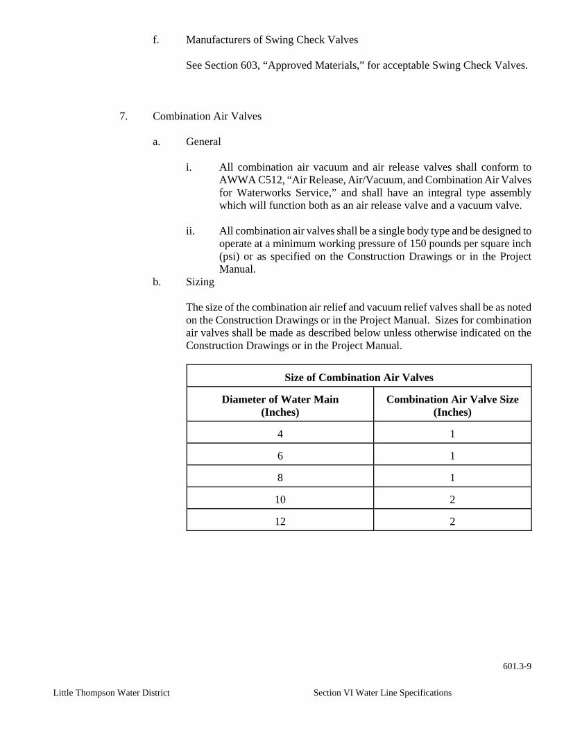
Little Thompson Water District Section VI Water Line Specifications
f. Manufacturers of Swing Check Valves
See Section 603, “Approved Materials,” for acceptable Swing Check Valves.
7. Combination Air Valves
a. General i. All combination air vacuum and air release valves shall conform to
AWWA C512, “Air Release, Air/Vacuum, and Combination Air Valves for Waterworks Service,” and shall have an integral type assembly which will function both as an air release valve and a vacuum valve.
ii. All combination air valves shall be a single body type and be designed to
operate at a minimum working pressure of 150 pounds per square inch (psi) or as specified on the Construction Drawings or in the Project Manual.
b. Sizing
The size of the combination air relief and vacuum relief valves shall be as noted on the Construction Drawings or in the Project Manual. Sizes for combination air valves shall be made as described below unless otherwise indicated on the Construction Drawings or in the Project Manual.
Size of Combination Air Valves
Diameter of Water Main (Inches)
Combination Air Valve Size
(Inches)
4
1
6
1
8
1
10
2
12
2
601.3-9

Little Thompson Water District Section VI Water Line Specifications
c. Connections
i. The inlet connection for the combination air valves shall be a one (1) inch for one (1) inch combination air valves and two (2) inches for two (2) inch combination air valves and conform to AWWA Standard C800, “Underground Service Line Valves and Fittings.”
ii. Connections on the outlet side of the combination air valves shall be
NPT tapered threads and shall be protected to minimize entry of debris and dirt into the valve.
d. The body of all combination air valves shall be either cast iron or ductile iron.
e. The working parts and seats of combination air valves shall be brass, stainless
steel, or other noncorroding material.
f. The float combination air valve shall be stainless steel.
g. Acceptable combination air valve manufacturers:
See Section 603, “Approved Materials,” for acceptable Combination Air Valves.
8. Pressure Regulating Valves
a. General
i. The pressure regulating valve (PRV) shall be a hydraulically operated, pilot controlled, diaphragm or piston actuated globe or angle valve.
ii. The valve shall be either cast iron or ductile iron with stainless steel or
bronze seats and all packing shall have either leather or rubber seals to provide tight closure and prevent metal to metal friction.
b. All pressure regulating valves shall have a fusion bonded epoxy coating interior
and exterior in accordance with AWWA Standard C550.
c. A vent with a ball valve needs to be installed on the top of the valve to allow flushing of the valve.
d. Pilot Control Valve
i. The pilot control valve used for controlling operation of the main valve
shall be a single seated, diaphragm operated and spring loaded type made of brass.
ii. The pilot control valve shall be attached to the main valve with piping of
brass, copper or stainless steel.
601.3-10

Little Thompson Water District Section VI Water Line Specifications
iii. Isolation valves shall be arranged for easy access to make adjustments
and for its removal from the main valve while the main valve remains under pressure.
e. The valve shall be designed to provide an access opening in the valve body for
removing the piston and other internal parts without removing the main valve body from the line.
f. The pressure reducing valve shall meet a minimum working pressure rating of
150 pounds per square inch (psi) unless otherwise specified on the Construction Drawings or in the Project Manual.
g. Flanged Connections
i. All connections shall be flanges drilled in accordance with ANSI B16.1,
“Cast Iron Pipe Flanges and Flanged Fittings,” unless otherwise specified.
ii. Flanges shall be machined to a flat face with a finish of 250 micro inches
AARH maximum or machined to a flat surface with a serrated finish in accordance with ANSI/AWWA Standard C115/A21.15.
iii. Flange gaskets shall be one-eighth (1/8) inch ring type of a synthetic
rubber material.
iv. All nuts and bolts shall be high strength, low alloy COR-TEN, manufactured in accordance with ANSI/AWWA C115/A21.15.
h. The body of the PRV shall be given a hydrostatic test of 50 percent (50%) more
than the operating pressure of the valve.
i. Acceptable manufacturers of pressure reducing valves are the following:
See Section 603, “Approved Materials,” for acceptable Pressure Regulating Valves.
9. Accessories
a. Valve Boxes
i. Valve boxes shall be manufactured of cast iron or ductile iron in
compliance with the requirements of ASTM A48.
ii. Valve boxes shall be three piece adjustable screw-type and complete with bases and lid accessories.
iii. A valve box shall be of sufficient length to reach from the top of the
valve body to at least one (1) inch above the final ground elevation.
601.3-11

Little Thompson Water District Section VI Water Line Specifications
iv. Extension pieces shall be those recommended by the valve box
manufacturer.
v. The word “WATER” shall be embossed with large letters across the lid for all potable water system buried valves.
vi. See Section 603, “Approved Materials,” for acceptable Valve Boxes.
b. Manholes
All manholes shall be manufactured in accordance with Section 601.8, “Vaults and Manholes” of these Water Line Specifications.
c. Meter Pits
All meter pits shall be manufactured in accordance with Section 601.7, “Service Connections,” of these Water Line Specifications.
C. Installation
1. In-Line Valves
a. All in-line valves shall be installed as specified in Standard Drawing 602.8,
“Valve Box Detail,” of these Water Line Specifications or on the Construction Drawings.
b. All valves shall have Mega lugs or an approved mechanical joint restraint device
installed.
c. All valves shall be supported with poured concrete or blocks prior to backfill as shown in Standard Drawing 602.8.
d. All valves shall be wrapped in polyethylene, prior to backfill. The polyethylene
material shall be as specified in Section 601.12, “Polyethylene Encasement” of these Water Line Specifications.
2. Valve Boxes
a. Valve boxes shall be installed on all buried valves as shown in Standard
Drawing 602.8. b. Valve boxes shall be installed so that no stress is transmitted to the valve.
c. Valve boxes which are to be set over the valve shall be centered, plumb and
directly over the operating nut and valve with the top of the box on grade.
d. The soil around the valve box shall be carefully compacted around the barrel with hand equipment to minimize misalignment and the settling of backfill.
601.3-12

Little Thompson Water District Section VI Water Line Specifications
3. Combination Air Valves
a. Combination air vacuum and air release valves shall be installed at high points
as specified on the Construction Drawings.
b. Combination air valves shall be installed in accordance with Standard Drawing 602.9, “1” Air Vac Assembly” or 602.10 “2” Air Vac Assembly.”
4. Pressure Regulating Valves
All pressure regulating valves (PRVs) shall be installed as shown on the Construction Drawings.
5. Valve Operation
All valves, which have been accepted by the District, shall be operated by District personnel only.
~ End of Section ~
601.3-13

Little Thompson Water District Section VI Water Line Specifications
601.4 FIRE HYDRANTS AND BLOW-OFFS
A. General
1. Description
This section addresses dry-barrel fire hydrants and blow-offs and includes the acceptable materials and construction practices which shall be used in the construction and installation of fire hydrants and blow-offs.
2. Material Delivery, Storage and Handling
a. Fire hydrants and blow-offs shall be handled, stored and protected in such a
manner as to prevent damage to materials, coatings and finishes.
b. All fittings and joints shall be kept free from dirt, oil and grease.
B. Material
1. Fire Hydrants
a. General
i. All fire hydrants shall be designed and manufactured in accordance with AWWA Standard C502, “Dry Barrel Fire Hydrants.” The additional requirements and exceptions to the AWWA standard contained herein shall also be applicable.
ii. All fire hydrants shall be a three-way, dry barrel type with a break
away traffic flange and designed for a minimum working pressure of 150 pounds per square inch (psi) unless otherwise specified on the Construction Drawings or in the Project Manual.
iii. Manufacturers shall test the body and main valve to a hydraulic
pressure of 300 pounds per square inch (psi).
v. All fire hydrants shall have a minimum main valve opening size of five and one quarter (5 1/4) inches.
vi. The hydrant shoe shall be coated with fusion bonded epoxy in
accordance with AWWA Standard C550, “Protective Epoxy Coatings for Valves and Hydrants.”
c. Nozzles
601.4-1

Little Thompson Water District Section VI Water Line Specifications
i. Fire hydrants shall be a three-way type with two (2) brass hose nozzles and one (1) brass pumper nozzle located on the same plane with the center line of the pumper nozzle. The nozzle shall be approximately and at least 18 inches above the ground line with the
pumper nozzle facing the street.
ii. The hose and pumper nozzles shall be threaded and locked in place by a stainless steel pin or screw. Sealing of the threaded connections shall be accomplished by the use of O-ring gaskets.
iii. Pumper Nozzle
aa. The fire hydrant’s pumper nozzle shall be four and one half
(4 2) inches in diameter with four (4) threads per inch.
bb. Pumper nozzle threads shall be right-handed and National Standard Thread (NST).
cc. A nozzle cap shall be furnished with security chains with
one end securely attached to the upper barrel section of the hydrant.
dd. The nozzle cap shall be furnished with a synthetic rubber
gasket installed in a retaining groove.
ee. The dimensions and shape of the nozzle cap nut shall be the same as the operating shaft nut as described in these specifications.
iv. Hose Nozzles
aa. The fire hydrant’s hose nozzles shall be two and one half (2
2) inches in diameter with seven and one half (7 2) threads per inch.
bb. The hose nozzle threads shall be right-handed NST.
cc. Nozzle caps shall be furnished with security chains with one
end of each securely attached to the upper barrel section of the hydrant.
dd. The nozzle cap shall be furnished with a synthetic rubber
gasket installed in a retaining groove.
ee. The dimensions and shape of the nozzle cap nut shall be the same as the operating shaft nut as described in these specifications.
c. Main Valve Assembly 601.4-2

Little Thompson Water District Section VI Water Line Specifications
i. The main valve of the hydrant shall be a five and one quarter (5 3) inch diameter compression type, which closes with the water pressure.
ii. The seat ring shall be bronze with a machined face and external
threads for threading into a bronze drain ring or a bronze bushed shoe to provide bronze to bronze seating for the main valve with O-rings for sealing.
iii. The main valve shall be a replaceable type faced with material such
as rubber, elastomer, polymer, leather, balata or other composition where the valve face bears on the seat ring to prevent leakage from the hydrant.
iv. The valve assembly shall include one or more drain valves, which
work automatically with the main valve and drain the barrel when the main valve is in the closed position. All drain tubes shall be bronze lined and sized large enough for the barrel to drain within 12 minutes when the barrel is sized for a five foot trench depth.
v. All parts of the main valve assembly shall be so designed that
removal of the assembly from the barrel is accomplished without excavation.
d. Operating Shaft Nut
i. The operating nut shall conform to the specifications listed for each Fire Protection District in Section 600.1 M (2).
ii. Bushings in the bonnet shall be so constructed that it will prevent
the operating nut from traveling during opening or closing operation. Also, the bushing shall house a gasket or seal to prevent moisture or foreign material from entering the lubricant reservoir.
iii. All hydrants shall be of the dry-top design where an oil reservoir
provides permanent lubrication of the operating nut threads.
iv. A stop nut located in the hydrant bonnet on the operating shaft shall prevent over travel of the main valve when being closed.
v. The hydrant shall be opened by turning the operating nut to the right
in a clockwise direction and shall have an arrow on top of the bonnet to designate the direction of opening.
e. Connections
601.4-3

Little Thompson Water District Section VI Water Line Specifications
i. Fire hydrant laterals shall be buried a minimum of five foot, unless specifically noted otherwise on the Construction Drawings or in the
Project Manual.
ii. The fire hydrant inlet connection shall be provided with a mechanical joint inlet to accommodate a six (6) inch diameter pipe complete with plain rubber gasket, approved mechanical joint restraint gland, and bolts and nuts in accordance with ANSI/AWWA C111/A 21.11.
iii. All nuts and bolts used in the connection of the fire hydrant to the
water line shall be high strength, low alloy COR-TEN, manufactured in accordance with ANSI/AWWA C115/A21.15.
iv. The auxiliary gate valve on the hydrant lateral shall be a six (6) inch
resilient seat gate valve with a valve box.
v. The hydrant tee on the main water line shall be a swivel tee.
vi. Tapping sleeves and valves are acceptable when connecting afire hydrant to an existing water main.
f. Color
i. All fire hydrant barrels shall be painted chrome yellow.
ii. The bonnet and caps shall be painted according to the measured fire
flow rates with 20 pounds per square inch (psi) residual pressure.
Color Codes for Anticipated Fire Flow Rates
Bonnet and Cap Color
Anticipated Fire Flow Rate
(Gallons per minute)
Light Blue
∃ 1,500
Green
∃ 1,000 - 1,500
Orange
∃ 500 - 1,000
Red
< 500 g. Manufacturers
See Section 603, “Approved Materials,” for acceptable Fire Hydrants.
2. Blow-offs
a. General
601.4-4

Little Thompson Water District Section VI Water Line Specifications
i. All blow-offs shall be designed and manufactured in accordance with AWWA Standard C502, “Dry Barrel Fire Hydrants.” The additional requirements and exceptions to the AWWA standard contained herein shall also be applicable.
ii. All blow-offs shall be a dry barrel type with a break away traffic
flange and designed for a minimum working pressure of 150 pounds per square inch (psi) unless otherwise specified on the Construction Drawings or in the Project Manual.
iii. All blow-offs shall have a minimum main valve opening size of two
(2) inches.
b. Nozzles
i. Blow-offs shall be a one-way type with one (1) hose nozzle approximately 18 inches above the ground line.
ii. The blow-off hose nozzle shall be two and one half (2 2) inches in
diameter with seven and one half (7 2) threads per inch.
iii. The hose nozzle threads shall be right-handed and NST.
iv. The blow-off hydrant shall be designed to break away easily at ground level.
c. The main valve assembly shall be screw-type and brass with a rubber seat
and serviceable from above grade.
d. Operating Shaft Nut
i. The operating nut shall be a 7/16” square operating nut with brass parts connecting to the main valve assembly.
ii. The operating nut shall be covered with a lockable cap.
e. Connections
i. Blow-off laterals shall be buried at the same depth as the main line, unless specifically noted otherwise on the Construction Drawings or in the Project Manual.
iii. The blow-off shall be provided with a threaded joint inlet to
accommodate a two (2) inch diameter brass pipe. iv. The blow-off assembly shall be connected to the main line with a
two (2) inch ball valve or as detailed in Standard Drawing 602.12, “Blow-Off
601.4-5

Little Thompson Water District Section VI Water Line Specifications
v. Assembly,” of these Water Line Specifications.
iv. Tapping sleeves and valves are acceptable when connecting to an existing water main.
e. All blow-offs shall be painted red.
g. Manufacturers
See Section 603, “Approved Materials,” for acceptable Blow Offs.
3. Hydrant Gravel
All fire hydrants and blow-offs shall be supported on a minimum of 18 inches of compacted hydrant gravel. The hydrant gravel shall be a well graded crushed stone or gravel conforming to the following gradation:
Hydrant Gravel Gradation
Sieve Size
Percent Passing
1 inch
100
¾ inch
90 – 100
3/8 inch
20 – 55
#4 sieve
0 – 10
#8 sieve
0 – 5
C. Installation
1. Inspection
a. All hydrants shall be inspected for the direction of opening, nozzle threading,
operating nut and cap dimensions, tightness of pressure-containing bolting, cleanliness of the inlet elbow, and handling damage or cracks.
b. All nonconforming or defective hydrants shall be removed from the site.
c. All thrust restraints on fire hydrants and blow-offs shall be inspected by the
District prior to backfill.
2. Installation
a. Fire Hydrant Installation 601.4-6

Little Thompson Water District Section VI Water Line Specifications
i. The fire hydrant shall be installed according to Standard Drawing 602.11, “Fire Hydrant Assembly” and these Water Line Specifications unless indicated otherwise on the Construction Drawings.
ii. Offset staking shall be provided for both vertical and horizontal
control. The fire hydrant shall be set to the elevation staked to ensure that the bury line of the hydrant is at the final grade.
iii. The joining of laterals, valves, and fire hydrants shall be handled in
the same manner as the pipe and fittings.
iv. The fire hydrant shall be installed vertically plumb with the pumper nozzle facing the street or the direction shown on the Construction Drawings.
v. The vertical distance from any finished surface to the centerline of
the pumper nozzle shall be approximately 18 inches.
vi. If a fire hydrant requires an extension, no more than one (1) extension section shall be installed unless otherwise approved by the District.
aa. Single fire hydrant extensions as recommended by the
hydrant manufacturer shall be used to raise fire hydrants one (1) foot to four (4) feet.
bb. Fire hydrants requiring more than four (4) feet of
adjustment to be placed at the proper elevation shall utilize a combination of Gradelok pipe and a single fire hydrant extension to achieve grade. The Gradelok pipe shall be installed as shown in Standard Drawing 602.11.
vii. After installation of the fire hydrant is complete, the oil/grease
reservoir shall be checked to ensure that it is full. If it is necessary to fill the reservoir, it shall be filled with the oil/grease, which is specified by the hydrant manufacturer.
b. Blow-off Installation
i. All blow-offs shall be installed according to Standard Drawing 602.12, “Blow-Off Assembly” and these Water Line Specifications, unless specified otherwise on the Construction Drawings.
ii. Offset staking shall be provided for both vertical and horizontal
control. The blow-off shall be set to the elevation staked to ensure that the bury line is at the final grade.
601.4-7

Little Thompson Water District Section VI Water Line Specifications
iii. The joining of laterals, valves, and blow-offs shall be handled in the same manner as the pipe and fittings.
iv. The blow-off shall be installed vertically plumb with the hose
nozzle facing the direction shown on the Construction Drawings.
v. The vertical distance from any finished surface to the centerline of the hose nozzle shall be approximately 18 inches, unless the blow-off is to be installed in a meter pit with fire hose connections as specified on the Construction Drawings.
3. Drainage
a. All fire hydrants and blow-offs shall be supported on a minimum of 18
inches of compacted hydrant gravel.
b. Hydrant gravel shall be placed to a minimum level of six (6) inches above the drain port and to a minimum distance of one (1) foot around the elbow.
c. The ground surrounding the fire hydrant or blow-off shall slope away from
the hydrant at a minimum grade of two percent (2%) toward the street.
4. Thrust Restraint
a. Thrust restraint shall be as specified in the Standard Drawings 602.11 and 602.12 unless otherwise specified on the Construction Drawings or in the Project Manual.
b. The concrete thrust block shall have a minimum bearing surface area of
four and one half (4 2) square feet behind the hydrant shoe unless another bearing surface area is specified on the Construction Drawings or in the Project Manual.
c. A sheet of eight (8) mil polyethylene film shall be placed between the
hydrant shoe and the concrete thrust block, and the barrel shall be wrapped to final dirt grade. The polyethylene material shall be as specified in Section 601.12, “Polyethylene Encasement” of these Water Line Specifications.
d. Care shall be taken when placing concrete thrust blocks so that the hydrant
weep holes remain free of obstruction.
5. Backfill
Carefully backfill and compact the soil around the fire hydrant or blow-off to provide adequate soil support to avoid transmitting shock movement to the lower barrel and inlet connection.
601.4-8

Little Thompson Water District Section VI Water Line Specifications
6. Tags
The District shall tag or label all fire hydrants with the District’s fire hydrant numbers.
7. Operation
a. Fire hydrants shall be opened and closed slowly and with care to prevent
water hammer on the main line.
b. District personnel shall instruct Contractors in the proper operation of fire hydrants when the Contractor is utilizing the hydrant for a metered water source.
~ End of Section ~
601.4-9

Little Thompson Water District Section VI Water Line Specifications 601.5 -1
601.5 TAPPING SADDLES AND SLEEVES A. General
1. Description
This section addresses the acceptable materials and installation of tapping saddles and sleeves.
2. Delivery, Storage and Handling
a. The materials shall be handled, stored and protected in a manner, which will
prevent damage to materials, coatings and finishes.
b. All materials shall be kept clean and free from dirt.
B. Material
1. Tapping Saddles
a. Tapping saddles shall be used for all three quarter (:) inch up to two (2) inch taps on water lines.
b. Tapping saddles shall be manufactured of materials in accordance with one (1)
of the following descriptions:
i. A bronze body with bronze double flat straps shall be used on all materials except PVC.
ii. A bronze body with an OD-controlled saddle shall be used on PVC.
iii. All saddles to have C.C. threads.
c. Nuts, bolts and accessories shall be used in accordance with the manufacturer’s
recommendations.
d. The tap saddle shall be designed for a minimum working pressure of 150 pounds per square inch (psi) unless otherwise specified on the Construction Drawings or in the Project Manual.
e. See Section 603, “Approved Materials,” for acceptable Tapping Saddles.
2. Tapping Sleeves
a. General
i. Tapping sleeves shall be used for all taps on water lines larger than two (2) inches and shall be designed for a minimum working pressure of 150 psi unless otherwise specified.

Little Thompson Water District Section VI Water Line Specifications 601.5 -2
ii. Flange
ii. Gaskets shall be made from new materials and the shape of the cross-
section of the gasket shall provide adequate seal for the design pressure. Gaskets shall be shop glued to the groove provided in the body section.
iii. Testing Outlet
A three quarter (3/4) inch NPT coupling shall be attached to the outlet nozzle of each tapping sleeve assembly complete with a three quarter (3/4) inch square head pipe plug.
b. Cast/Ductile Iron Tapping Sleeves
i. The ductile iron sleeve shall consist of a heavy ductile iron cylinder,
coated with a one (1) millimeter thick exterior bituminous coating or fusion bonded epoxy coating in accordance with AWWA Standard C550.
ii. Flanges
aa. Ductile iron pipe with flanged joints shall be designed,
manufactured, tested, inspected, and marked in accordance with the provisions of these Water Line Specification and ANSI/AWWA Standard C115/A21.15, “Flanged Cast Iron and Ductile Iron Pipe with Threaded Flanges,” except as herein modified.
bb. All flanges shall be sized and drilled in accordance with
ASME/ANSI B16.1, “Cast Iron Pipe Flanges and Flanged Fittings,” unless otherwise specified on the Construction Drawings or in the Project Manual.
iii. All flange nuts and bolts shall be high-strength low-alloy COR-TEN,
manufactured in accordance with ANSI/AWWA C111/A-21.11. iv. See Section 603, “Approved Materials,” for acceptable Ductile Iron
Tapping Sleeves.
c. Stainless Steel Tapping Sleeves
i. The sleeve body shall be manufactured from Type 304 stainless steel.
aa. The flanges shall be 18-8 Type 304 stainless steel with a recess
to accept standard tapping valves. bb. The flange shall be class D and manufactured in accordance with
AWWA Standard C207, “Steel Pipe Flanges for Waterworks Service – Size 4 Inch through 144 Inch.”

Little Thompson Water District Section VI Water Line Specifications 601.5 -3
iii. Full enclosure gasket shall cover the entire length of the sleeve.
iv. See Section 603, “Approved Materials,” for acceptable Stainless Steel
Tapping Sleeves.
d. Fabricated Steel Mechanical Joint Tapping Sleeves
i. The fabricated steel sleeve shall consist of a two part fabricated cylinder,
with fusion bonded epoxy coating in accordance with AWWA Standard C550.
ii. All steel plate used in fabrication of the steel tapping sleeves shall
conform to ASTM A36 or A285, Grade C.
iii. Flanges
aa. Flanges shall be fabricated from steel plate and all dimensions shall conform to AWWA Standard C207 Class D.
bb. Flanges shall be machined to a flat rate with finish of 250 micro
inches or machined to a flat surface with a serrated finish in accordance with AWWA Standard C207. The machined face shall also be recessed for tapping valves.
iv. See Section 603, “Approved Materials,” for acceptable Fabricated Steel
Mechanical Joint Tapping Sleeves.
e. Fabricated Steel Tapping Sleeves
i. All steel plate used in fabrication of the steel tapping sleeves shall conform to ASTM A36 or A285, Grade A or ASTM 283, Grade C.
ii. The fabricated steel sleeve shall have a fusion bonded epoxy coating in
accordance with AWWA Standard C550.
iii. Flanges
aa. Flanges shall be fabricated from steel plate and all dimensions shall conform to AWWA Standard C207 Class D.
bb. Flanges shall be machined to a flat rate with finish of 250 micro
inches or machined to a flat surface with a serrated finish in accordance with AWWA Standard C207. The machined face shall also be recessed for tapping valves.
iv. Bolts and nuts shall be carbon steel, ASTM grade B or Type 304
stainless steel.

Little Thompson Water District Section VI Water Line Specifications 601.5 -4
v. Epoxy coated inside and outside
C. Installation
1. Tapping Saddlesand Sleeves
a. Tapping saddles and sleeves shall be installed in accordance with the manufacturer’s recommendation.
b. Prior to installation, all coatings, oil, scale, and dirt shall be removed from the
saddle and pipe to provide a clean seat for the gasket.
c. The gasket shall be wiped clean prior to installation.
d. Final nut tightening shall be performed with a torque-limiting wrench to the torque level recommended by the manufacturer.
2. Tapping Procedure
a. Prior to any wet tap, the Contractor shall provide the District with a minimum of
24 hours advance notice. All wet taps four (4) inches and larger shall be accomplished under the supervision of the Designated District Representative.
b. Separation
i. Adjacent tap saddles and sleeves shall be separated by a minimum of 12 inches edge to edge.
ii. Tap saddles and sleeves shall be a minimum of three (3) feet from the
nearest pipe joint.
c. Tapping sleeves shall be tested to the manufacturer’s specifications.
d. The tapping valve shall be supported with blocks prior to attaching the tapping machine to the valve.
d. Thrust Blocks
i. Taps four (4) inches and larger require a thrust block as detailed in Section 601.10, “Thrust Blocks and Other Restraints,” and Standard Drawing 602.4, “Horizontal Thrust Block Detail.”
ii. The thrust block shall be poured prior to any water entering the new
water line through the wet tap.
f. Tapping equipment shall be of good quality, used for the purpose intended and used in accordance with the manufacturer’s instructions.
g. The coupon from the wet tap shall be turned over to the District at the
conclusion of the tap.

Little Thompson Water District Section VI Water Line Specifications 601.5 -5
- End of Section -

Little Thompson Water District Section VI Water Line Specifications 601.6 -1
601.6 COUPLINGS, FLANGE ADAPTORS AND REPAIR BANDS
A. General
1. Description
This section addresses iron and PVC couplings, flange adaptors and repair bands and includes the acceptable materials and construction practices which shall be used in the installation of couplings, flange adaptors and repair bands.
2. Material Delivery, Storage and Handling
a. The material shall be handled, stored and protected in a manner, which will
prevent damage to materials, coatings and finishes.
b. All materials shall be kept clean and free from dirt.
B. Material
1. General
a. All iron pipe couplings shall be manufactured in accordance with AWWA Standard C219, “Bolted Sleeve-Type Couplings for Plain End Pipe,” and all PVC couplings shall be manufactured in accordance with AWWA Standard C900, “Polyvinyl Chloride (PVC) Pressure Pipe and Fabricated Fittings, 4 Inch Through 12 Inch, for Water Distribution.”
b. All couplings shall be of a gasketed, sleeve type with a diameter to properly fit
the pipe.
c. Couplings and flange adaptors shall be designed to relieve mechanical stress in pipelines due to thermal expansion and contraction, differential settlement or misalignment, and mechanical vibration.
d. Iron couplings and flange adaptor bodies shall be fabricated from cast iron, steel
or ductile iron.
e. All nuts and bolts shall be high-strength low-alloy COR-TEN, manufactured in accordance with ANSI/AWWA C111/A-21.11 “Rubber Gasket Joints for Ductile Iron Pressure Pipe and Fittings,” or stainless steel.
e. Gaskets shall be synthetic rubber compounded with other products to produce a
material, which will not deteriorate from age, heat or exposure to air under normal storage conditions. The gaskets shall also possess the quality of resilience and ability to resist cold flow of water so that the joint will remain sealed and tight indefinitely when subjected to shock, vibration, pulsation, temperature, or adjustments of the pipeline.
2. Flexible Iron Couplings

Little Thompson Water District Section VI Water Line Specifications 601.6 -2
a. Flexible iron couplings shall be used when joining pipes of the same outside
diameter (OD).
b. Flexible iron couplings shall consist of a sleeve, which shall fit over the ends of two (2) pipe sections to be joined.
c. The flexible iron coupling shall form a watertight seal by compressing resilient
wedge-shaped gaskets between the ends of the sleeve and the pipe sections.
d. The gaskets shall be compressed by two (2) retainer rings bolted to one another on the outside of the flexible coupling sleeve.
e. See Section 603, “Approved Materials,” for acceptable Flexible Iron Couplings.
3. Transition Couplings
a. Transition couplings shall be used when joining pipes of dissimilar OD.
b. Transition couplings shall consist of a sleeve, which shall fit over the ends of
two (2) pipe sections to be joined.
c. The transition coupling shall form a watertight seal by compressing resilient wedge-shaped gaskets between the ends of the sleeve and the pipe sections.
d. The gaskets shall be compressed by two (2) retainer rings bolted to one another
on the outside of the transition coupling sleeve.
e. See Section 603, “Approved Materials,” for acceptable Transition Couplings. 4. Insulated Couplings
a. Insulated couplings shall be used when joining pipes of dissimilar metal
materials.
b. Insulating couplings shall consist of a sleeve, which shall fit over the ends of two (2) pipe sections to be joined and provide insulation against electrical transmission between two (2) different pipe materials.
c. The insulating coupling shall form a watertight seal by compressing resilient
wedge-shaped gaskets between the ends of the sleeve and the pipe sections.
d. The gaskets shall be compressed by two (2) retainer rings bolted to one another on the outside of the insulating coupling sleeve.
e. See Section 603, “Approved Materials,” for acceptable Insulated Couplings.
5. Flexible PVC Couplings

Little Thompson Water District Section VI Water Line Specifications 601.6 -3
a. Flexible PVC couplings shall be used when joining PVC pipes of the same outside diameter (OD).
b. Flexible PVC couplings shall consist of a sleeve, which shall fit over the ends of
two (2) PVC pipe sections to be joined.
c. The flexible PVC coupling shall form a watertight seal by compressing gaskets between the ends of the sleeve and the pipe sections.
d. The couplings may be slip-type couplings up to six (6) inches in diameter or
compression type coupling up to two (2) inches in diameter. e. See Section 603, “Approved Materials,” for acceptable Flexible PVC Couplings.
6. Flange Adaptors
a. Flange adaptors shall consist of a sleeve, which shall fit over the end of one (1)
pipe section and have a flanged connection on the other end of the sleeve.
b. The flange adaptor shall form a watertight seal by compressing a resilient wedge-shaped gasket between the end of the sleeve and the pipe section and a standard flange connection on the other end.
c. The gasket shall be compressed by one (1) retainer ring bolted to the flanged end
on the outside of the flanged adaptor.
d. All connections shall be flanges drilled in accordance with ANSI B16.1, “Cast Iron Pipe Flanges and Flanged Fittings,” unless otherwise specified on the Construction Drawing or the Project Manual.
e. Flanges shall be machined to a flat face with a finish of 250 micro inches AARH
maximum or machined to a flat surface with a serrated finish in accordance with ANSI/AWWA Standard C115/A21.15.
f. See Section 603, “Approved Materials,” for acceptable Flange Adaptors.
7. Repair Bands
a. Stainless steel repair bands (clamps) may be used to cover and repair holes,
cracks, and breaks in all types of pipe.
b. The repair band shall be manufactured of 18-8 stainless steel, type 304.
c. The gasket shall have tapered ends and be compressed by the entire band and be able to fully enclose the pipe.
d. See Section 603, “Approved Materials,” for acceptable Repair Bands.
C. Installation

Little Thompson Water District Section VI Water Line Specifications 601.6 -4
1. Install all flexible couplings, transition couplings, insulating couplings, flange adaptors, and repair bands in accordance with the manufacturer’s recommendations.
2. Prior to installation, all coatings, oil, scale, and dirt shall be removed from the coupling
or adaptor and provide a clean seat for the gasket on the pipe.
3. Wipe the gasket clean prior to installation.
4. Tighten the bolts progressively until all bolts have a uniform tightness. Final tightening shall be performed with a torque-limiting wrench to the torque level recommended by the manufacturer.
5. Restraint rod, and rods with insulating kits shall be installed where required with
insulating couplings, to provide restraint against pipe thrust.
6. If the iron coupling is to be buried, the coupling shall be wrapped in polyethylene and taped to seal prior to backfill.
~ End of Section

Little Thompson Water District Section VI Water Line Specifications
601.7 SERVICE CONNECTIONS
A. General
1. Description
This section addresses the acceptable materials and installation of corporation stops, service lines, meters, meter setters and meter pits for all types of service connections.
2. Material Delivery, Storage and Handling
a. The material shall be handled, stored and protected in a manner, which will
prevent damage to materials, coatings and finishes.
b. All materials shall be kept clean and free from dirt.
3. Maintenance and Correction
The Contractor and/or Developer shall maintain and repair all service lines, meter pits, and associated appurtenances which leak, were installed incorrectly, or otherwise prove to be defective for a period of two (2) years after the District’s final acceptance date of the Work.
4. Developer Responsibility
The meter pit yoke, dome and lid shall be provided by the District for installation on all line extensions for new development. All additional materials shall be provided by the Developer.
B. Material
1. Tapping Saddles
Tapping saddles shall be as specified in Section 601.5, “Tapping Saddles and Sleeves,” of these Water Line Specifications.
2. Corporation Stops
a. Corporation stops shall conform to AWWA Standard C800, “Underground
Service Line Valves and Fittings.” The additional requirements and exceptions to the AWWA standard contained herein shall also be applicable.
i. Corporation stops shall be full opening ball type and constructed of
brass.
601.7-1

Little Thompson Water District Section VI Water Line Specifications
iii. Corporation stop inlet threads for tapping saddles shall be cc taper thread.
iii. Corporation stop outlets shall use a compression or flared connection.
iv. Corporation stops shall be used for all taps which are two (2) inches or
smaller.
b. See Section 603, “Approved Materials,” for acceptable Corporation Stops.
3. Tapping Valves
a. Tapping valves shall conform to Section 601.3, “Valves,” of these Water Line Specifications.
b. Tapping valves shall be used for all taps which are larger than two (2) inches or
larger.
4. Service Lines
a. Two (2) Inches or less.
i. Copper
aa. Copper pipe may be used for service lines, which are two (2) inches or less.
bb. Copper services shall conform to AWWA Standard C800,
“Underground Service Line Valves and Fittings.”
cc. Copper services shall be type K only.
ii. Polyethylene
aa. Polyethylene may be used for service lines, which are two (2) inches or less.
bb. Polyethylene services shall conform to AWWA Standard C901,
“Polyethylene (PE) Pressure Pipe and Tubing, 2 Inch Through 3 Inch, for Water Service.”
cc. Polyethylene shall be SDR 9 rating with working pressure rating
of 200 pounds per square inch (psi).
b. Two (2) Inches and Larger
i. Pipe for service lines two (2) inches and larger shall be as specified on the Construction Drawings or in the Project Manual.
601.7-2

Little Thompson Water District Section VI Water Line Specifications
ii. Ductile iron pipe service lines shall conform to the specifications in Section 601.2, “Ductile Iron Pipe and Fittings.”
iii. PVC service lines shall conform to the specifications in Section 601.1,
“PVC Pipe.”
5. Couplings
a. Service couplings shall use a brass compression or flared connection up to 2” in size; over 2” in size shall use mechanical joint or iron pipe thread connections.
b. See Section 603, “Approved Materials,” for acceptable Service Couplings.
6. Curb Stops
a. General
i. Curb stops shall use a brass, compression or flared, or iron pipe thread connection up to two (2) inches in size.
ii. Curb stops over two (2) inches in size shall use mechanical joint or iron
pipe thread connections
iii. Curb stops shall be ball type full opening.
iv. Curb stops shall be used when specified on the Construction Drawings or in the Project Manual.
b. See Section 603, “Approved Materials,” for acceptable Curb Stops. c. Valve Boxes for Curb Stops
For services larger than two (2) inches, the valve box shall be as specified in Section 601.3, “Valves,” and Standard Drawing 602.8 of these Water Line Specifications.
7. Meter Setters
a. Three quarter (3/4) inch and one (1) inch
i. All meter setters shall be tandem style and have a meter stop inlet valve
with a lock wing and a dual check valve with replaceable cartridges on the outlet in accordance with the manufacturer’s accessory options.
ii. See Section 603, “Approved Materials,” for acceptable Meter Setters.
b. One and one half (1 2) inch and two (2) inches
601.7-3

Little Thompson Water District Section VI Water Line Specifications
Refer to Construction Drawing 602.19 “1 2 & 2” Meter Vault.”
c. Meter setters larger than two (2) inches shall require Construction Drawings approved by the District.
8. Meters
a. Service meters shall be magnetic drive displacement meters and conform to
AWWA C700, “Cold-Water Meters - Displacement Type, Bronze Main Case.”
b. Master meters shall be turbine, compound or mag meter type meters and conform to AWWA 701, “Cold-Water Meters - Turbine Type, for Customer Service,” or AWWA 702, “Cold-Water Meters - Compound Type.”
c. See Section 603, “Approved Materials,” for acceptable Service and Master
Meters.
9. Meter Pits and Vaults
a. For five eighth (5/8) inch to one (1) inch meters
i. Meter pits shall be 20 inches in diameter for five eighths (5/8) and three quarter (3/4) inch meters and 24 inches in diameter for one (1) inch meters.
ii. Meter pits shall be a minimum of 36 inches in length.
iii. Meter pits shall be constructed of a rigid polyethylene or approved
equal.
iv. Meter pit covers shall be constructed of cast iron or aluminum with cast iron outer lids and frost-proof plastic inner lids.
v. The minimum allowable opening for meter pit covers shall be 11 inches
in diameter.
vi. All meter pit covers shall have a 27/32 inch worm lock with a standard waterworks pentagon head.
b. One and one half (1 2) inch and two (2) inch meters
i. Meter vaults shall meet the following minimum specifications and shall
be constructed as specified on the Construction Drawings and in the Project Manual. Refer to Drawing 602.19
ii. Meter vaults shall be constructed from precast concrete box sections that
are traffic rated if the vault is to be located in the right-of-way.
601.7-4

Little Thompson Water District Section VI Water Line Specifications
iii. Meter vaults shall have the following minimum vault dimensions:
Meter Size (Inches) Inside Vault Dimension (Feet x Feet)12 6 x 8 2 6 x 8
iv. Meter vault covers shall be Bilco hatches (or an approved equal) with a
minimum 24 inch by 24 inch opening.
v. Watertight vaults shall be provided unless otherwise indicated on the Construction Drawings or in the Project Manual.
c. Larger than Two (2) Inches Meters
All meter vaults for meters larger than two (2) inches shall be evaluated and specified on an individual basis by the District.
C. Installation
1. General
a. Meter setters shall be installed according to the manufacturer’s
recommendations, in accordance with the specifications contained herein, the Standard Drawing 602.13, “Residential Meter Pit Detail,” and/or on the Construction Drawings.
b. Meter pit and vaults shall be installed by the Contractor, unless otherwise
directed by the District.
c. Meter pits and vaults shall not be installed in any street, alley, parking area, driveway or sidewalk unless approved by the District.
d. There shall be no landscaping (trees, shrubs, boulders, etc.) or structures
(retaining walls, fences, etc.) allowed within three (3) feet of the meter pit or vault.
e. The ground surrounding meter pits and vaults shall slope away from the lid.
f. There shall be no plumbing connections inside the meter pit or vault.
g. The meter pit lid shall be adjusted to one (1) inch above the final grade.
2. Inspection
a. The Contractor shall ensure that the corporation stop and any couplings remain
exposed until inspection and approval by the District.
b. All tap and service inspections shall be scheduled 24 hours in advance with the District.
601.7-5

Little Thompson Water District Section VI Water Line Specifications
c. Meter pits and valve boxes shall be at finished grade at the time of final acceptance of the water line and services.
3. Service Taps
a. All taps shall be made with a tapping saddle in accordance with these Water
Line Specifications and the manufacturer’s recommendations, unless otherwise approved by the District.
b. Tapping equipment shall be of good quality, used for the purpose intended, and
used in accordance with the manufacturer’s recommendations.
c. The Contractor shall make all taps and install all meter pits and setters prior to disinfection and hydrostatic testing of the new water main.
d. The Contractor shall not make any service taps on existing water lines without
prior approval by the District.
e. The Contractor shall provide 24 hours advance notice to the District before a tap on an existing water line is made.
f. The Contractor shall adjust valve boxes and meter pits to the horizontal location
and to the final grade as specified on the Construction Drawings.
g. Taps shall not be made within three (3) feet of any joint or fitting.
h. Taps shall be separated by at least one and one half (1 2) feet (measured along the pipe length), even when taps are made on opposite sides of the pipe.
i. Taps, which are made on the same side of the pipe and within 10 feet of each
other (measured along the pipe length), shall be staggered fifteen degrees.
j. Tap saddles shall be installed as specified in Section 601.5, “Tapping Saddles and Sleeves,” of these Water Line Specifications.
4. Corporation Stops
Corporation stops in ductile iron pipe, PVC, steel, cast iron, asbestos cement and any other pipe material shall be installed be means of a tapping saddle unless otherwise indicated on the Construction Drawings or in the Project Manual.
5. Service Line
a. District Service Line
i. All service lines shall be installed a minimum of four (4) feet below
finished grade.
601.7-6

Little Thompson Water District Section VI Water Line Specifications
ii. Necessary service line grade adjustments shall be made as close to the main as possible.
iii. The service line shall be sized as in Section 600.3 (I) “Minimum Service
Line Size.”
b. Tapholder Service Line
The Tapholder service line shall be installed and maintained by the Tapholder.
6. Meters, Meter Setter, and Meter Pits and Vaults
a. Meters, meter setter, and meter pits and vaults shall be installed according to
Standard Drawing 602.13, “Residential Meter Pit,” 602.19 “1 2 & 2” Meter Vault.”or 602.14, “Residential One (1) Inch Fire Sprinkler Meter Pit,” unless otherwise specified on the Construction Drawings.
b. All meters, meter setter, and meter pits shall be supplied by the District for
installation by the Contractor.
c. All meter vaults shall be supplied by the Contractor for installation by the Contractor.
d. The Contractor shall adjust meter pits and vaults to the horizontal location and to
the final grade as specified on the Construction Drawings.
~ End of Section ~
601.7-7
Little Thompson Water District Section VI Water Line Specifications
601.8 VAULTS AND MANHOLES
A. General
1. Description
This section addresses vaults and manholes and includes the acceptable materials and construction practices which shall be used in the manufacture and installation of all vaults and manholes.
2. Material Delivery, Storage and Handling
a. Do not deliver precast concrete sections to the Work Site until the concrete has
attained at least 80% of the specified strength.
b. Do not place cast in place concrete during rain, sleet or snow unless adequate protection is provided.
B. Material
1. Precast Concrete
Concrete for precast concrete vaults and manholes shall conform to the specifications of Section 601.13, “Cast In Place Concrete,” of these Water Line Specifications and as otherwise specified on the Construction Drawings or in the Project Manual.
2. Cast In Place Concrete
Concrete for cast in place concrete vaults and manholes shall conform to the specifications of Section 601.13, “Cast In Place Concrete,” of these Water Line Specifications and as otherwise specified on the Construction Drawings or in the Project Manual.
3. Grout
a. Premixed Grout
i. Premixed grout shall be nonmetallic.
ii. See Section 603, “Approved Materials,” for acceptable Premixed Grout.
b. Job-Mixed Grout
601.8-1

Little Thompson Water District Section VI Water Line Specifications
i. Job-mixed grout shall use the following ratio
aa. One (1) part Portland Cement conforming to ASTM C207, Type I/II.
bb. One (1) part sand conforming to ASTM C144.
cc. One (1) part shrinkage correcting aggregate.
iii. See Section 603, “Approved Materials,” for acceptable Shrinking
Correcting Aggregate. iii. Job-mixed mortar shall be Sand-Cement grout conforming to the
following ratio:
aa. One (1) part Portland Cement conforming to ASTM C207, Type I/II.
bb. Two (2) parts sand conforming to ASTM C144.
cc. One half (2) part hydrated lime conforming to ASTM C207,
Type S.
4. Steps
a. Location and Spacing
i. All steps shall be spaced 12 inches apart on center.
ii. The maximum distance from the cover to the top step shall be 24 inches.
iii. The maximum distance from the bench of the manhole or floor of the vault to the lowest step shall be 18 inches.
b. Material
i. All steps shall be made of one of the following materials
aa. Aluminum or aluminum with plastic coating
bb. Copolymer polypropylene plastic conforming to ASTM C478
and ASTM C497.
ii. See Section 603, “Approved Materials,” for Acceptable Steps
5. Watertight Seals
a. Pipe Penetration Seals
601.8-2

Little Thompson Water District Section VI Water Line Specifications
i. Watertight seals shall be installed at all pipe penetrations.
ii. See Section 603, “Approved Materials,” for acceptable Pipe Penetration Seals.
b. Concrete Seam Seals
i. Watertight “plastic” gasket seals shall be installed at all concrete seams.
ii. See Section 603, “Approved Materials,” for acceptable Concrete Seam
Sealer.
6. Reinforcement Material
Reinforcement material shall be as specified in Section 601.13 or 601.14 of these Water Line Specifications unless otherwise specified on the Construction Drawings or in the Project Manual.
7. Form Material
Form material shall be as specified in Section 601.13 of these Water Line Specifications unless otherwise specified on the Construction Drawings or in the Project Manual.
C. Installation
1. General
a. Flat slab concrete tops shall be installed on all manholes.
b. Flat slab concrete tops with risers for hatch-type doors shall be installed on all
vaults.
c. All manholes and vaults located within county or city right-of-ways shall be rated for appropriate traffic loading.
2. Manholes and Vaults
a. The manhole and vault rings and cover shall be as specified on the Construction
Drawings or in the Project Manual.
b. Manholes and vaults shall be constructed at the location and elevation indicated on the Construction Drawings.
c. Unless otherwise specified on the Construction Drawings, the top of the
manhole and vault shall be plumb and at a finished grade of the Work. Precast concrete adjustment rings shall be used to bring the ring and cover to grade.
601.8-3

Little Thompson Water District Section VI Water Line Specifications
d. Manholes and vaults which are installed in an area subject to high groundwater shall be sealed both inside and outside and shall be watertight.
e. Adjustment rings shall be joined with a minimum one (1) inch mortar bed.
f. All joints and other imperfections shall be filled with nonshrink grout to provide
a smooth finished appearance.
~ End of Section ~
601.8-4

Little Thompson Water District Section VI Water Line Specifications
601.9 PIPE CASING, BORING AND JACKING
A. General
1. Description
This section addresses casing pipe, boring, jacking, and directional boring and includes the acceptable materials and construction practices which shall be used in the installation of casing pipe and directional bores.
2. Material Delivery, Storage and Handling
a. The material shall be handled, stored and protected in a manner, which will
prevent damage to materials, coatings and finishes.
b. All materials shall be kept clean and free from dirt.
3. Quality Assurance
a. Material used for directional bores shall meet the minimum pressure requirements as specified on the Construction Drawings or in the Project Manual.
b. Increased pipe strength shall be provided as necessary to withstand any jacking
loads or directional bore stresses.
c. The specified thickness on the Construction Drawings or in the Project Manual for the pipe casing is based upon the superimposed loads per the Design Engineer’s calculations and not upon the loads, which may be placed on the pipe as a result of jacking operations.
B. Material
1. Steel Casing
a. Steel
i. New smooth wall steel casing pipe shall conform to ASTM A139, Grade
“B.”
ii. The smooth steel casing pipe shall have minimum yield strength of 35,000 pounds per square inch (psi).
601.9-1

Little Thompson Water District Section VI Water Line Specifications
iii. The minimum wall thickness of the steel casing pipe shall be one quarter (1/4) inch or as determined by the agency granting the crossing permit.
iv. Clean used pipe that is in good condition and conforms to the
requirements of this specification may be used with prior approval of the District.
b. Exterior Coating
i. The steel casing pipe shall have an exterior coating of epoxy polyamide
which conforms to AWWA Standard C210, “Liquid Epoxy Coating Systems for the Interior and Exterior of Steel Water Lines,” or, if specified on the Construction Drawings or in the Project Manual, a coal-tar enamel coating which conforms to AWWA Standard C203, “Coal Tar Protective Coatings and Linings for Steel Water Pipelines, Enamel and Tape - Hot Applied.”
ii. The minimum thickness of the exterior coating shall be 16 mil.
iii. If approved by the District, the Contractor may omit the exterior coating,
one sixteenth (1/16) of an inch shall be added to the required thickness of the steel casing pipe.
iv. All field welds shall be painted with an epoxy polyamide exterior
coating which conforms to AWWA Standard C210 or, if specified on the Construction Drawings or in the Project Manual, a coal-tar enamel exterior coating which conforms to AWWA Standard C203.
2. Casing Seals
a. Casing seals shall be of the following:
i. High density rubber casing seals with stainless steel straps.
ii. High density polyethylene mechanical seals with stainless steel
hardware. b. See Section 603, “Approved Materials,” for acceptable Casing Seals.
3. Casing Chocks and Skids
Casing chocks shall be as shown on the Construction Drawings or in the Project Manual and shall be constructed of one of the following materials:
i. Stainless steel
ii. Polymer runners
iii. See Section 603, “Approved Materials,” for acceptable Casing Chocks.
601.9-2

Little Thompson Water District Section VI Water Line Specifications
4. High Density Polyethylene Pipe
a. High density polyethylene (HDPE) pipe used for directional boring shall conform to AWWA Standard C901, “Polyethylene (PE) Pressure Pipe and Tubing, 2 Inch Through 3 Inch, for Water Service,” or AWWA Standard C906, “Polyethylene (PE) Pressure Pipe and Fittings, 4 Inch Through 63 Inch, for Water Distribution.”
b. The minimum pressure class of HDPE 3408 shall be SDR 9 rated to 200 pounds
per square inch (psi), unless a higher pressure class of pipe is specified on the Construction Drawings or in the Project Manual.
c. See Section 603, “Approved Materials,” for acceptable HDPE pipe.
C. Installation
1. General
a. Casing pipe and carrier pipe shall be installed as specified in the Standard
Drawing 602.6, “Standard Pipe Casing Detail,” of these Water Line Specifications, unless specified otherwise on the Construction Drawings or in the Project Manual.
b. Directional bore specifications shall be as shown on the Construction Drawings
or in the Project Manual.
c. If specified on the Construction Drawings or in the Project Manual, a 17 pound high potential magnesium anode shall be installed at each end of the casing pipe.
d. All spaces between the casing pipe and the earth shall be filled.
e. The annular space between the casing and the carrier pipes shall be left vacant.
f. The ends of the casing pipe shall be sealed with casing seals.
2. Welding
a. Fabrication and welding of the steel casing pipe shall conform to the requirements of AWWA Standard C200, “Steel Water Pipe 6 Inches and
Larger.”
b. The ends of the steel casing pipe shall be beveled for field welding.
c. Each section of casing pipe shall be welded with a full penetration butt weld around the entire circumference of the joint to form a watertight continuous conduit capable of resisting all stresses, including jacking stresses.
601.9-3

Little Thompson Water District Section VI Water Line Specifications
d. All field welds shall be painted with an epoxy polyamide exterior coating which
conforms to AWWA Standard C210 or, if specified on the Construction Drawings or in the Project Manual, a coal-tar enamel exterior coating which conforms to AWWA Standard C203.
3. Location
a. Casing pipe shall be installed at the grade and alignment shown on the
Construction Drawings by either open trench excavation, jacking methods or directional boring.
b. Vertical and horizontal offset staking shall be provided at both ends of bored or
jacked crossings.
c. Grade and alignment shall not deviate by more than half the diameter of the casing pipe on the Construction Drawings.
4. Sealing
a. Seals
The ends of the casing pipe shall be sealed as specified on the Construction Drawings or in the Project Manual.
b. Voids
Grouting shall be required when material surrounding the casing is being removed during casing installation and substantial voids are created.
5. Casing Chocks and Skids
a. Stainless Steel or Polymer Casing Chocks
i. The chocks shall be installed according to the manufacturer’s installation instructions.
ii. There shall be a minimum of three (3) chocks installed per pipe joint.
6. HDPE Direct Placement
a. HDPE pipe installed by directional boring methods shall be a minimum of four
and one half (4 2) feet below the finished grade.
b Fusion of the HDPE pipe and fittings shall be in accordance with the pipe manufacturer’s recommendations.
c The fittings for pulling the HDPE pipe through the bored tunnel shall be fused to
the pipe and allowed to properly cool before pulling the pipe. 601.9-4

Little Thompson Water District Section VI Water Line Specifications
d. The safe pull strength of the HDPE pipe shall not be exceeded without pull force limiting devices.
e. Once the HDPE pipe has been pulled through the bored tunnel, the pipe shall be
allowed to “relax” and contract adequately, depending on the size of the pipe and the length of the bore, before tying in to existing water lines.
~ End of Section ~
601.9-5

Little Thompson Water District Section VI Water Line Specifications
601.10 THRUST BLOCKS AND OTHER RESTRAINTS
A. General
1. Description
This section addresses thrust blocks and other restraint systems and includes the acceptable materials and construction practices which shall be used in the installation of thrust blocks and other restraint systems.
2. Material Delivery, Storage and Handling
a. The material shall be handled, stored and protected in a manner, which will
prevent damage to materials, coatings and finishes.
b. All materials shall be kept clean and free from dirt.
c. Do not place cast in place concrete during rain, sleet or snow unless adequate protection is provided.
B. Material
1. General
a. Thrust blocks and/or other restraint systems shall be constructed at all bends and
fittings as indicated on the Construction Drawings or in the Project Manual.
b. If concrete thrust blocks cannot be used, push-on and mechanical joints shall be restrained with mechanical restraint systems.
c. The mechanical restraint system to be utilized shall be shown on the
Construction Drawings or in the Project Manual.
2. Thrust Blocks
a. Concrete
i. All concrete used for thrust blocks shall conform to Section 601.13, “Cast In Place Concrete,” of these Water Line Specifications.
ii. All concrete used for thrust blocks shall have a minimum 28 day
strength of 3,000 pounds per square inch (psi).
601.10-1

Little Thompson Water District Section VI Water Line Specifications
b. Forms
i. All forming for concrete thrust blocks and anchors shall be done by bulk heading around the shape of the thrust block.
ii. Filled sacks and wood used to form concrete thrust blocks shall be left in
place in the trench and buried during backfilling operations.
3. Mechanical Joint Restraint Devices
a. Gland body and restraint components shall be manufactured from ductile iron in accordance with ASTM A536.
b. Restraint devices shall be rated for a minimum test pressure of 150 psi unless
otherwise specified on the Construction Drawing or in the Project Manual. c. Restraint devices shall be equipped with torque limiting twist off nuts to tighten
the gripping wedges. After the twist-off nuts are removed, a hex head nut shall remain for future removal of the device.
d. Restraint devices shall be color coded for use on ductile iron and PVC pipe.
e. See Section 603, “Approved Materials,” for acceptable Mechanical Joint
Restraint Devices.
4. Flange Adaptor Restraints
a. Gland body shall be manufactures from ductile iron in accordance with ASTM 536 and drilled in accordance with ANSI B 16.1.
b. Restraint devices shall be rated for a minimum test pressure of 150 psi unless
otherwise specified on the Construction Drawing or in the Project Manual. c. Set Screws shall be constructed of steel.
d. Restraint devices shall be color coded for use on ductile iron and steel pipe.
e. See Section 603, “Approved Materials,” for acceptable Flange Adaptor Restraints.
5. Restrained Joint Pipe and Fittings
a. Restrained joint pipe and fittings shall be manufactured from ductile iron in
accordance with Section 601.2, “Ductile Iron Pipe and Fittings,” of these Water Line Specifications.
601.10-2
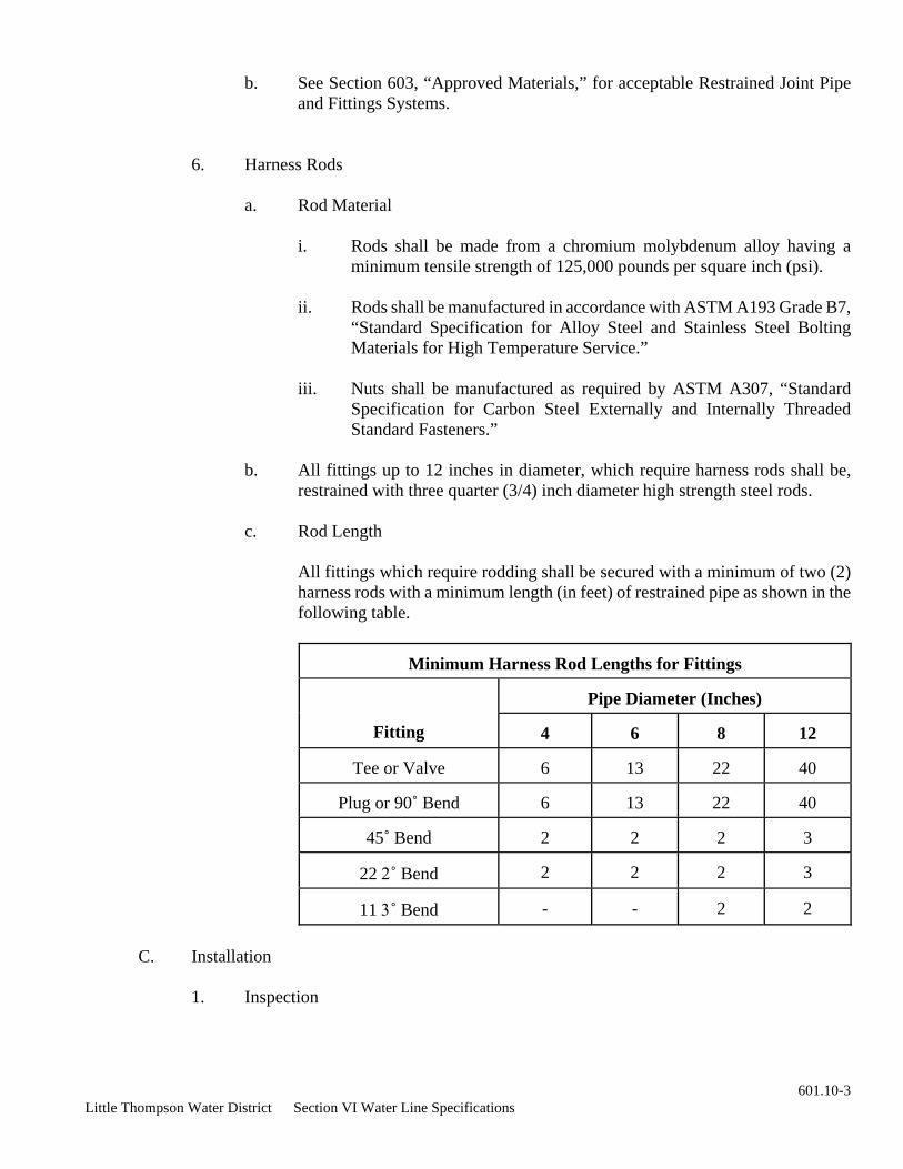
Little Thompson Water District Section VI Water Line Specifications
b. See Section 603, “Approved Materials,” for acceptable Restrained Joint Pipe and Fittings Systems.
6. Harness Rods
a. Rod Material
i. Rods shall be made from a chromium molybdenum alloy having a minimum tensile strength of 125,000 pounds per square inch (psi).
ii. Rods shall be manufactured in accordance with ASTM A193 Grade B7,
“Standard Specification for Alloy Steel and Stainless Steel Bolting Materials for High Temperature Service.”
iii. Nuts shall be manufactured as required by ASTM A307, “Standard
Specification for Carbon Steel Externally and Internally Threaded Standard Fasteners.”
b. All fittings up to 12 inches in diameter, which require harness rods shall be,
restrained with three quarter (3/4) inch diameter high strength steel rods.
c. Rod Length
All fittings which require rodding shall be secured with a minimum of two (2) harness rods with a minimum length (in feet) of restrained pipe as shown in the following table.
Minimum Harness Rod Lengths for Fittings
Pipe Diameter (Inches)
Fitting
4
6
8
12
Tee or Valve
6
13
22
40
Plug or 90˚ Bend
6
13
22
40
45˚ Bend
2
2
2
3
22 2˚ Bend
2
2
2
3
11 3˚ Bend
-
-
2
2
C. Installation
1. Inspection
601.10-3

Little Thompson Water District Section VI Water Line Specifications
a. The Contractor shall notify the District Representative at least 24 hours before concrete is poured for thrust blocks.
b. All thrust blocks shall be inspected by the District Representative prior to
pouring the thrust block and before backfilling the excavation around the thrust block.
c. All other restraint systems shall be inspected by the District Representative prior
to backfilling the excavation around the fittings and pipe.
2. Thrust Blocks
a. General
i. Care shall be taken not to block outlets or to cover bolts, nuts, clamps or other fittings.
ii. A bond breaker shall be placed between the pipe or fitting and the thrust
block to aid in ease of future removal.
iii. If a thrust block one (1) cubic yard or larger is to be poured, it shall be separated by cardboard or wood into manageable sections.
iv. The Standard Drawings 602.4, “Horizontal Thrust Block Detail,” and
602.5, “Vertical Thrust Block Detail,” of these Water Line Specifications shall show the size and shape of thrust blocks for all fittings and provide the minimum bearing surface area for each fitting. Thrust block information on the Construction Drawings or in the Project Manual shall supersede the Standard Drawings.
v. The thrust block shall bear against undisturbed earth. The minimum
bearing surface areas are the minimum areas required to bear against the undisturbed trench wall.
vi. The soil bearing capacity is not sufficient to provide adequate restraint
based on the minimum bearing areas shown on the Standard Drawings or Construction Drawings or in the Project Manual, then either the minimum bearing area shall be increased to the size that will ensure adequate restraint or restrained joint pipe and fittings may be utilized.
vii. If the main must be placed immediately into service, harness rods may
be used in lieu of the thrust block or other materials may be used to support the thrust. The support must be approved prior to pouring concrete and shall be of such design as to support the thrust until the concrete has set. The support shall not considered a substitute for the concrete.
b. Concrete
601.10-4

Little Thompson Water District Section VI Water Line Specifications
i. Newly placed concrete shall be allowed to set undisturbed for a minimum curing time of 24 hours prior to filling the water line unless additional approved thrust restraint has been provided.
ii. Before placing concrete, all equipment for mixing and transporting the
concrete shall be clean.
iii. When concrete is deposited against ground without the use of forms, the ground shall be thoroughly moistened.
iv. Backfill may be placed over the thrust block once the surface has set
sufficiently to resist the weight of the backfill. However, no tamping or compacting shall be allowed above the thrust block for a minimum of 24 hours after concrete placement.
v. All debris, water or ice shall be removed from the place to be occupied
by the concrete. Concrete shall not be placed in frozen subgrade.
vi. Sack concrete shall not be acceptable for thrust blocks.
c. Forms
i. No horizontal struts or braces required for trench shoring shall remain in the concrete thrust blocks.
ii. Prior to placing the concrete, the forms and trench shall be inspected and
approved by the Designated District Representative.
3. Mechanical Joint Restraint Devices
a. Mechanical joint restraint glands shall be required on all mechanical joint fittings and installed in accordance with the manufacture’s installation instructions.
b. A torque indicating wrench shall be used to tighten the bolts to the torque range
specified by AWWA Standard C600, “Installation of Ductile Iron Water Mains and Their Appurtenances.”
c. The bolts shall be tightened by partially tightening the bottom bolt first, then the
top bolt, next the bolts at either side, and finally the remaining bolts. Repeat the process until all bolts are within the appropriate range of torque.
4. Other Restraint
a. Flange Adaptors
601.10-5

Little Thompson Water District Section VI Water Line Specifications
Flange adaptors shall be installed in accordance with the manufacture’s installation instructions.
b. Restrained Joint Pipe and Fittings
The restrained joint pipe and/or fittings shall be installed in accordance with the manufacture’s installation instructions.
d. Harness Rods
i. Harness rods may be required to anchor vertical bends, horizontal and
vertical offsets, reducers, ninety degree (90˚) horizontal bends, and connections where tees are used if specified on the Construction Drawings or in the Project Manual or required by field conditions.
ii. Where harness rods are required inside of vaults or other structures, they
shall be connected to flanged fittings by means of steel plate flange lugs as shown on the Construction Drawings.
iii. After installation, plastic wrap and/or coat the harness rods and nuts with
Polyken Pipeline Primer No. 927 (Kendall) or an approved equal.
~ End of Section ~
601.10-6

Little Thompson Water District Section VI Water Line Specifications
3. Delivery, Storage and Handling
a. The material shall be handled, stored and protected in a manner, which will prevent damage to materials, coatings and finishes.
C. Installation
601.11-1
601.11 TRACER WIRE
A. General
This section addresses tracer wire and includes the acceptable materials and construction practices which shall be used in the installation of tracer wire.
B. Material
1. Tracer Wire
Tracer wire shall be a standard, single, 12 gauge, insulated, UL underground rated, solid copper wire.
2. Splices
a. All tracer wire splices require the use of a waterproof, compression-type splice
kit.
b. Manufacturers
See Section 603, “Approved Materials” for acceptable Direct Bury Splice Kit.
1. General
a. The tracer wire shall be attached to the top of every piece of pipe with tape to
prevent movement or damage during backfill operations.
b. Install tracer wire as shown in Standard Drawings 602.8, “Valve Box Detail,” and 602.17, “Tracer Wire Splice Detail,” of these Water Line Specifications.
2. Service Lines
a. Tracer wire May be utilized on meter pits located more than ten (10) feet from the main water line.
b. The tracer wire shall be brought up in the meter pit and a six (6) foot length of wire shall be left in the meter pit.
Little Thompson Water District Section VI Water Line Specifications
c. The tracer wire shall be wrapped several times around the main water line to anchor it, but the wire shall not be spliced into the tracer wire on the main line.
3. Splicing
a. All tracer wire splices shall be as shown in Standard Drawing 602.17, “Tracer Wire Splice Detail,” of these Water Line Specifications.
b. Tracer wire coating of the wires to be connected shall be stripped back one half (2) inch.
c. 3M DBR Direct Bury Splice Kit
A wire nut shall be used to connect the bare metal ends of the tracer wire, and the wire nut shall be placed inside the waterproof connector according to the manufacturer’s installation instructions.
d. An overhand knot shall be tied six (6) inches from the splice to prevent the wires from pulling out of the waterproof connector.
e. The tracer wire shall be taped to the pipe on either side of the splice.
f. The waterproof connector shall be taped to the pipe to prevent movement during backfill.
4. Bringing to Surface
a. Tracer wire shall be brought to the surface as specified in the Construction
Drawing.
~ End of Section ~
601.11-2

Little Thompson Water District Section VI Water Line Specifications
This section addresses polyethylene encasement and bond breakers and includes the acceptable materials and construction practices which shall be used in the installation of polyethylene wrap.
2. The raw material used to manufacture polyethylene film shall be in accordance with ASTM Standard D1248.
3. The polyethylene film shall meet the following minimum test requirements:
Tensile Strength 1200 psi
Dielectric Strength 800 V/mil thickness
C. Installation
1. Polyethylene Encasement of Pipe
601.12 POLYETHYLENE ENCASEMENT
A. General
B. Material
1. All polyethylene material shall be manufactured in accordance with AWWA Standard
C105, “Polyethylene Encasement for Ductile Iron Pipe Systems.”
Elongation 300%
Thickness 0.008 inches (8 mil) with minimum tolerance not exceeding 10% of nominal Melt Index 0.4 max
4. Delivery, Storage and Handling
All materials shall be handled and stored in accordance with the manufacturer’s specifications. This includes, but is not limited to, protection from ultraviolet radiation (direct sunlight) and prolonged heat. Polyethylene, which exhibits any signs of ultraviolet deterioration, shall not be used.
a. Install polyethylene as shown in Standard Drawing 602.16, “Field Installation of
Polyethylene,” of these Water Line Specifications.
b. Place the tube polyethylene material on the pipe prior to lowering the pipe into the trench.
c. Pull the tube over the length of pipe. Tape the tube to the pipe at the pipe joint.
Fold the tube material around the adjacent spigot end and wrap with tape to hold the tube in place. Excess material shall be neatly drawn up around the pipe barrel, folded on top of the pipe, and taped in place.
601.12-1

Little Thompson Water District Section VI Water Line Specifications
d. Overlap the first tube with an adjacent tube (as specified by the manufacturer) and secure with tape. The polyethylene material covering the pipe will be loose. The excess material shall be neatly drawn up around the pipe barrel, folded on top of the pipe, and taped in place.
e. Repair any tears in the polyethylene material prior to backfill.
f. Carefully backfill with clean material that will not damage the polyethylene
material.
2. Double Encasement
a. When specified on the Construction Drawings or as directed by the District, the ductile iron pipe or fittings shall be wrapped in two (2) layers of polyethylene
b. Situations where double polyethylene encasement may be required:
i. Crossing another water line
ii. Crossing above sanitary or storm sewer
iii. Crossing fiber optic utilities
iv. Crossing gas pipe lines
v. Installing ductile iron pipe near cathodically protected underground
utilities
vi. Installing ductile iron pipe in casing
c. The two (2) tubes of polyethylene shall be installed in the same manner as a single tube.
d. The excess material from both tubes shall be neatly drawn up around the pipe barrel, folded on top of the pipe, and taped into place.
3. Polyethylene Bond Break
a. Cut a piece of polyethylene tube lengthwise to open.
b. Place the open tube under the fitting and fold the tube material around the fitting.
c. Wrap with tape around the pipe on either side of the fitting to hold the polyethylene in place.
d. Excess material shall be neatly drawn up around the fitting, folded on top of the fitting, and taped in place.
601.12-2

Little Thompson Water District Section VI Water Line Specifications
601.12-3
e. Repair any tears in the polyethylene material prior to backfill.
f. Carefully backfill with clean material that will not damage the polyethylene material.
~ End of Section ~

Little Thompson Water District Section VI Water Line Specifications
2. Job Conditions
a. Do not place cast in place concrete during rain, sleet or snow unless adequate protection is provided.
b. Cold Weather
i. Concrete shall not be placed unless the air temperature is at least 30˚ Fahrenheit and rising.
ii. The temperature of the mix shall not be less than 50˚ Fahrenheit at the time of placement.
iii. If heated water and/or an accelerator is used, the above temperature restrictions may be waived by the District; however, water shall not be heated to a temperature exceeding 150˚ Fahrenheit. Heated concrete shall not be warmer than 80˚ Fahrenheit when placed.
iv. Protect placed concrete from freezing during the curing period.
601.13 CAST IN PLACE CONCRETE
A. General
This section addresses cast in place concrete for thrust restraints, vaults, encasement, and cut off walls.
1. Material Delivery, Storage and Handling
a. All material shall be handled, stored and protected in a manner, which will prevent damage to the material.
c. Hot Weather
i. Precautions shall be taken when placing concrete when the air
temperature adjacent to the concrete placement is 90˚ Fahrenheit and higher.
ii. The temperature of the mix shall not be more than 85˚ Fahrenheit at the
time of placement.
601.13-1

Little Thompson Water District Section VI Water Line Specifications
c.
5. Admixtures
iii. Do not use cement which has reached a temperature of 170˚ Fahrenheit or more.
iv. To facilitate the placement of concrete in hot weather, the aggregate and
the water may be cooled.
B. Material
1. General
a. Concrete shall have a minimum of six (6) sacks per cubic yard and shall be allowed to develop a minimum compressive strength of 3,000 pounds per square inch (psi) at 28 days.
b. Concrete shall have a maximum allowable water/cement ratio of one half (2 or 0.5)
by weight.
c. The water cement ratio may be increased to 0.56 by weight if a water-reducing agent is used.
d. The maximum elapsed time from the time water is added to the mix until concrete is in place shall not exceed one and one half (1 2) hours.
2. Cement
a. Portland cement shall conform to ASTM C150.
b. Portland cement shall be Type II or Type V.
Tricalcium aluminate (Ca3Al) in the Type II cements shall not exceed five percent (5%).
d. Twelve (12), 24, or 48 hour concrete mixtures may be used with prior approval of the District. Acceptable type of early strength cement is Type III or an approved equal.
3. Aggregates
All fine and coarse aggregate shall conform to ASTM C33.
4. Water
All water shall be clean and free from objectionable quantities of silt, organic matter, alkali, salts, oils, acids, and other impurities that may be deleterious to concrete reinforcement.
601.13-2
Little Thompson Water District Section VI Water Line Specifications
a. An air-entraining agent shall be used in all concrete and shall conform to ASTM C260.
b. A water-reducing admixture may be used.
i. The water-reducing admixture shall conform to ASTM C494, for Type A or Type D chemical admixture.
ii. The water-reducing admixture shall not contain any calcium chloride.
iii. The water-reducing admixture shall be compatible with the cement being used.
c. Accelerators
Accelerators shall conform to ASTM C494.
d. Fly Ash
i. When fly ash is used in concrete, the cement replacement shall not exceed 20%.
ii. Class C or Class F fly ash shall conform to ASTM C618.
e. Any admixtures except air entraining agents and accelerators must have prior approval from the Designated District Representative.
6. Forms
a. Where “Smooth and Finish” or “Grout Cleaned Finish” is specified on the
Construction Drawings or in the Project Manual, prefabricated plywood panel forms, job built plywood forms, forms lined with plywood or fiberboard or steel forms shall be used.
b. Where “Rough Form Finish” is specified on the Construction Drawings or in the
Project Manual, unlined wooden forms may be used.
c. If forms are not specified on the Construction Drawings or in the Project Manual, then only use forming material if required by field conditions. In such cases, forming material may be scrap lumber, rocks, soil, or sacks of sand or soil.
7. Reinforcement
a. All deformed reinforcing bars shall conform to ASTM A615 or ASTM A996.
b. All reinforcing bars shall be either Grade 40 or 60.
c. All welded steel wire fabric shall conform to ASTM A185.
601.13-3

Little Thompson Water District Section VI Water Line Specifications
C. Installation
1. General
b. Deposit concrete in a continuous operation until each section is complete and regulate the rate of placement so that the concrete remains plastic and flows into position.
5. Curing
a. Finished concrete shall be cured by protecting it against moisture loss, rapid temperature change, and from rain, flowing water, and mechanical damage for a minimum of 72 hours after placement.
b. Concrete shall be maintained at a minimum temperature of 50˚ Fahrenheit during the curing period.
601.13-4
a. The Contractor is responsible for protecting the concrete from traffic and the elements.
b. The Contractor shall notify the District, a minimum of 24 hours advance notice prior to the placement of concrete.
c. The District shall inspect the excavation prior to placement of concrete and before backfilling around the concrete.
2. Forms
a. Placement of forms, if required shall conform to the specifications on the Construction Drawings or in the Project Manual.
b. Form work shall be inspected by the District prior to placement of the concrete.
3. Reinforcement
a. Pacement of reinforcement, if required shall conform to the specifications on the Construction Drawings or in the Project Manual.
b. Reinforcement shall be inspected by the District prior to placement of the concrete.
4. Placement
a. Convey concrete from the mixer to the final position as rapidly as practicable without segregation or loss of material.
~ End of Section ~

Little Thompson Water District Section VI Water Line Specifications
All precast concrete parts shall be delivered, stored, handled, and protected in a manner, which will prevent damage to the materials.
B. Material
1. Manholes
c. The barrels and flat slab tops shall conform to ASTM C478.
d. All precast concrete parts shall be made with Type II cement.
e. The vaults and flat slab tops shall conform to ASTM C478.
f. All precast concrete parts shall be made with Type II cement.
3. Concrete
Concrete shall conform to Section 601.13, “Cast In Place Concrete,” of these Water Line Specifications unless otherwise specified on the Construction Drawings or in the Project Manual.
4. Reinforcement
Reinforcement shall conform to Section 601.13, “Cast In Place Concrete,” of these Water Line Specifications unless otherwise specified on the Construction Drawings or in the Project Manual.
5. Grout (Nonshrink)
g. Pre-Mixed Grout Manufacturers
See Section 603, “Approved Materials” for acceptable Pre-Mixed Grout Manufacturers
601.14 PRECAST CONCRETE
A. General
The section addresses precast concrete products and accessories for vaults and manholes
1. Material Delivery, Storage and Handling
2. Vaults
h. Job Mixed Grout Manufacturers 601.14-1

Little Thompson Water District Section VI Water Line Specifications
6. Steps
a. Steps shall be constructed of aluminum or plastic in accordance with Federal Specification QQ-A-200/A.
b. Provide aluminum steps with plastic coating or bituminous coating to protect from corrosion from concrete or nonshrink grout.
c. Steps shall be 12 inches on center (O.C.)
d. See Section 603, “Approved Materials” for acceptable Step Manufacturers
7. Preformed Plastic Gaskets
a. Gasket shall be manufactured in conformance with Federal Specification SS-S00210 (GSA-FSS), Type I, Rope Form.
b. Gaskets shall be one and one-half (1 2) inches in diameter for a 48 inch diameter manhole.
c. See Section 603, “Approved Materials” for acceptable Pre-Formed Plastic Gasket Manufacturers
C. Installation
1. Construct manholes and vaults at locations indicated on the Construction Drawings.
2. Set manhole sections or vaults plumb.
3. Use precast adjustment rings or additional barrel sections to bring cover to grade.
4. Join manhole and vault sections to lids using preformed flexible plastic gaskets.
5. All joint surfaces shall be clean and dry during installation.
6. Fill all lifting holes and other imperfections with nonshrink grout.
See Section 603, “Approved Materials” for acceptable Job Mixed Grout Manufacturers
~ End of Section ~
601.14-2

Little Thompson Water District Section VI Water Line Specifications
a. Flow fill shall be mixed and delivered in a ready mixed state.
b. Proportion ingredients to produce a well-graded flowable mix that is consistent with the submitted mix design.
i. Weights shall be based upon aggregates in a saturated, surface dry condition.
c. Proportions
ii. Sand: 1845 pounds
iii. Coarse Aggregate: 1700 pounds
iv. Water: 325 pounds (39.0 gallons)
d. Physical Properties
i. Minimum 28-day compressive strength: 60 pounds per square inch (psi)
ii. Slump: six (6) to eight (8) inches
iii. Air: six percent (6%) to eight percent (8%)
iv. Water/Cement Ratio (pounds/pound): 5.4
B. Material
1. Cement shall conform to ASTM C150 and be Type II.
601.15 FLOWABLE CONCRETE BACKFILL
A. General
This section addresses flowable concrete backfill (flow fill).
1. Material Delivery, Storage and Handling
a. All material shall be handled, stored and protected in a manner, which will prevent damage to the material.
2. Job Conditions
ii. Air entraining agent shall be used to increase flowability.
i. Cement: 60 pounds
601.15-1

Little Thompson Water District Section VI Water Line Specifications
2. Aggregates
a. Fine aggregate shall conform to ASTM C33.
b. Coarse aggregate shall conform to ASTM C33, Size #57.
3. Water shall be from a clean and fresh source.
4. Admixtures
a. The air-entraining agent shall conform to ASTM C260.
b. Fly ash shall not be used.
C. Installation
1. Install flow fill in the locations shown on the Construction Drawings.
2. The trench shall be backfilled with flow fill above the bedding elevation to the finished asphalt grade or as shown on the Construction Drawings.
3. The flow fill shall be compacted with vibration techniques to completely fill voids if required by the Designated District Representative.
4. Do not commence surface replacement work until flow fill has sufficient strength to support construction equipment without observable deformation.
5. Excavate excess flow fill to the subgrade elevation.
6. Place base course, gravel surfacing, or pavement over the flow fill in accordance with the Construction Drawings.
~ End of Section ~
601.15-2

Little Thompson Water District Section VI Water Line Specifications
601.16-1
601.16 GRAVEL SURFACING
A. General
This section addresses gravel surfacing to be provided at the indicated locations on the Construction Drawings and where existing gravel surfacing has been removed by construction operations.
1. Application
a. Private Easement
Aggregate shall be applied at a minimum rate of 900 tons per mile of road surface or as otherwise specified on the Construction Drawings or in the Project Manual.
b. Public Right-of-Way
Aggregate shall be applied at the rate specified by the entity granting the right-of-way permit.
B. Material
1. Private Easement
Aggregate shall be pit run, locally available natural gravel, crushed stone, or crushed gravel, which meets the requirements of CDOT Class 6 road base material.
2. Public Right-of-Way
Material for gravel surfacing shall be as specified by the entity granting the right-of-way permit.
C. Installation
1. Private Easement
a. Gravel Removal
i. Windrow existing roadbed material away from the trench area prior to excavating the trench.
ii. The existing material shall be removed to the point of transition between native clay material and the roadbed material.
ii. The existing material shall be placed back over the trench area after the trench has been prepared in accordance with Section 601.19,

Little Thompson Water District Section VI Water Line Specifications
~ End of Section ~
601.16-2
“Trenching, Backfilling and Compacting,” of these Water Line Specifications unless otherwise specified on the Construction Drawings or in the Project Manual.
b. Gravel Application
i. Spread the gravel over the surface of the designated area at a rate of 900 tons per mile and combine with the existing roadbed material by manipulating until all voids in the material are filled.
ii. During manipulation, the surfacing material shall be sprinkled with
sufficient moisture to obtain compaction.
iii. The combined materials shall be spread uniformly over the surface area and compacted with a roller until the roller rides the surface and a stable base has been formed.
v. No finish rolling is required but this layer shall be maintained moist by
sprinkling until the following layer of gravel is applied.
c. Final Grading
Grade areas to receive gravel surfacing in such a manner that the edges of the gravel surfacing, when placed as specified and to the designated uniform thickness, will be at the same elevation as adjacent earth unless otherwise specified on the Construction Drawings.
2. Public Right-of-Way
Material for gravel replacement shall be as specified by the entity granting the right-of-way permit.

Little Thompson Water District Section VI Water Line Specifications 601.17 -1
601.17 ASPHALT PAVEMENT
A. General
This section addresses asphalt pavement repair.
1. Material Delivery, Storage and Handling
a. All material shall be handled, stored and protected in a manner, which will prevent damage to the material.
2. Quality Assurance
The words “CDOT Standard Specifications” as used in this section refer to the State Department of Highways, Division of Highways, State of Colorado, “Standard Specifications for Road and Bridge Construction,” adopted 1999.
B. Material
1. Private Easement
a. Aggregates
i. Base Coarse: Reference “CDOT Standard Specifications,” Section 703.03.
ii. Pavement: Reference “CDOT Standard Specifications,” Section 703.04, Grading, Grading “E.”
b. Mineral Filler Material
Filler material: Reference “CDOT Standard Specifications,” Section 712.03 and AASHTO M17.
c. Hydrated Lime
Reference “CDOT Standard Specifications,” Section 712.03.
d. Bituminous material
i. Reference “CDOT Standard Specifications,” Section 702.
ii. Asphalt cement: Penetration grade of AC-10, AASHTO M226, six percent (6%) by weight of mix.
iii. Prime coat: Liquid asphalt, MC-70, AASHTO M82.
iv. Tack coat: Emulsified asphalt, CSS01, AASHTO M140.

Little Thompson Water District Section VI Water Line Specifications 601.17 -2
2. Public Right-of-Way
e. Soil Sterilizing Agent
Reference “CDOT Standard Specifications,” Section 217.02.
Material for asphalt pavement repair shall be as specified by the entity granting the right-of-way permit.
C. Installation
1. Private Easement
a. Pavement Removal
i. When shown on the Construction Drawings, remove, dispose of, and
restore to original or better condition asphalt concrete pavement, curbs, drives, sidewalks, and gravel surfacing.
ii. Remove and dispose of any existing pavement as required to complete the Work.
iii. Remove pavement, drive or sidewalk to clean, straight lines.
iv. Saw cutting is required if a clean, straight line cannot be obtained by other methods.
b. Subgrade Preparation
i. Compact subgrade in accordance with Section 601.19, “Trenching,
Backfilling and Compacting,” of these Water Line Specifications.
ii. Sterilize subgrade soil prior to construction of the asphalt base course in accordance with Section 217.03 of the “CDOT Standard Specifications.”
c. Base Course
i. Construct base course in accordance with Section 304 of the “CDOT
Standard Specifications.”
ii. Apply primer coat and tack coat before placement of asphalt concrete in accordance with Section 407 of the “CDOT Standard Specifications.”
iii. Construct asphalt concrete pavement to the alignment, dimensions, and grade shown on the Construction Drawings in accordance with Section 401 of the “CDOT Standard Specifications.”
2. Public Right-of-Way

Little Thompson Water District Section VI Water Line Specifications 601.17 -3
Material for asphalt pavement repair shall be as specified by the entity granting the right-of-way permit.
~ End of Section ~

Little Thompson Water District Section VI Water Line Specifications 601.18 -1
601.18 PIPE INSTALLATION
A. General
This section addresses the installation of water distribution lines and includes the acceptable products, materials, and construction practices.
1. Quality Assurance
Water system installations shall conform to the regulations of the Colorado Department of Public Health and Environment and the Water Quality Control Commission.
2. Installation
a. The pipe shall normally be installed with the bells pointing in the direction that the Work is progressing unless a variation is approved by the District.
b. The Contractor shall employ measures to prevent the opening of joints during bedding and backfilling operations. Bedding material shall not be dropped onto unsupported pipe, which has been set to alignment and grade.
c. Pipe shall be laid and maintained at required lines and grades as specified in the approved Construction Drawings.
d. The pipe shall be secured in place with the specified bedding consolidated under and around the pipe.
e. The pipe shall be installed so that a uniform positive or negative grade is maintained between the designed high and low points.
f. The minimum depth of cover shall be four and one half (4 2) feet from the finished grade to the top of the pipe, except as otherwise indicated on the Construction Drawings.
g. The maximum depth of cover shall be six (6) feet from the finished grade to the
top of the pipe, except as otherwise indicated on the Construction Drawings or approved by the District.
h. Foreign material, including trench water, shall not be permitted in the pipe.
i. The open ends of the pipe shall be plugged with a watertight plug when pipe
laying is not in progress.
j. Measures shall be used to prevent uplifting or floating of the water line prior to completion of the backfilling operations.
k. Pipe shall not be installed under the following conditions:
i. When the trench contains water.
Little Thompson Water District Section VI Water Line Specifications 601.18 -2
m. Pipe Alignment and Grade
i. In laying pipe, the maximum tolerance permitted is to set line within ∀six (6) inches and grade within ∀three (3) inches.
iii. The pipe shall be kept in alignment by deflecting joints, using shorter lengths of pipe (minimum 10 feet long), or installing bends, when laying pipe in curves.
ii. When the trench bottom is unstable.
iii. When weather conditions are unsuitable.
aa. Temperature is less than 10˚ Fahrenheit. District approval is required when the temperature is 32Ε Fahrenheit or less.
bb. Snowing or raining heavily.
cc. High winds.
l. Underground Interference
i. It shall be the responsibility of the Contractor to verify the locations of all interferences.
ii. The Contractor shall exercise care when working in order to protect all
underground interferences and shall be fully responsible for any and all damage caused by his operation.
ii. Fittings, valves, and hydrants shall be installed at the specified locations
and elevations, unless written permission to deviate is obtained from the District.
iv. Any changes in alignment and grade must be authorized by the District
and shall be accomplished by the installation of additional fittings or “breaking” of joints.
v. To form a long radius curve, the deflection shall not exceed 80% of the
pipe manufacturer’s recommendations for maximum deflection.
n. Deviation from Alignment and Grade Caused by Other Structures
i. Whenever obstructions interfere to such an extent that an alteration in the Work is required, the District will determine the best method of correction.
ii. The District may change the Construction Drawings and order a deviation from alignment and grade, or the District may instruct the

Little Thompson Water District Section VI Water Line Specifications 601.18 -3
b. Pipe material shall not be interchanged except where another type of pipe material is specifically indicated on the Construction Drawings or in the Project Manual.
2. Valves
All valves shall be as specified in Section 601.3 “Valves” of these Water Line Specifications.
Contractor to arrange with the Owners of the structure for its removal, relocation or reconstruction, as best fits the conditions.
o. Sanitary Sewer Structures
i. Horizontal Clearance
Water mains shall be located at least 10 horizontal feet from any existing or proposed sanitary sewer when installed parallel. This shall be clear distance measured edge to edge. Refer to Standard Drawing 602.7, “Sewer Crossing.”
ii. Vertical Clearance
When a water main crosses a sanitary sewer line including manholes, the water main must be laid above the sanitary sewer line with a clearance of at least 18 inches from the top of the sewer line to the bottom of the water line. If this vertical separation cannot be obtained, then special construction criteria shall be used. . Refer to Standard Drawing 602.7, “Sewer Crossing.”
iii. No water main or pipe shall come into contact with any part of a sewer line or a sewer manhole.
iv. Whenever sewer facilities interfere to such an extent that an alteration in
the Work is required, the District Designated Representative will determine the best method of correction.
B. Material
1. Pipe
a. Ductile iron and PVC pipe and fittings shall be as specified in Section 601.1, “PVC Pipe,” and Section 601.2, “Ductile Iron Pipe and Fittings,” of these Water Line Specifications.
3. Fire Hydrants and Blow-Offs
All fire hydrants and blow-offs shall be as specified in Section 601.4 “Fire Hydrants and Blow-Offs” of these Water Line Specifications.

Little Thompson Water District Section VI Water Line Specifications 601.18 -4
All PVC pipe shall be installed in accordance with AWWA Standard C605, “Underground Installation of Polyvinyl Chloride (PVC) Pressure Pipe and Fittings for Water,” with the exceptions and additions in this specification.
a. Bedding
Before the pipe is laid, the subgrade shall be prepared by backfilling with clean, uniformly graded sand, 3/4 inch washed rock, or approved native material so as to provide a uniform and continuous bearing and support for the pipe at every point between bell holes. Bedding shall be installed in accordance with Standard Drawing 602.1, “PVC Pipe Bedding Detail.” No blocking of pipe shall be permitted.
b. Groundwater Barriers
Groundwater barriers shall be installed every 500 feet in the trench if non-native material is used for backfill. Unless otherwise specified on the Construction Drawings or in the Project Manual
c. Joining Push-On Joints
i. The inside of the bell, the outside of the spigot end, and the rubber gasket shall be thoroughly cleaned to remove oil, grit, and other foreign matter, before joining two lengths of pipe.
ii. A thin film of gasket lubricant shall be as specified by the pipe manufacturer.
iii. The spigot end of the pipe shall be placed in the socket with care to prevent the joint from contacting the ground. The joint shall be completed by pushing the pipe “home” with a slow and steady pressure without jerky or jolting movements. Pipe furnished without a depth mark shall be marked before assembly to ensure full insertion of the joint. The spigot end of field cut pipe lengths shall be filed or ground to resemble the spigot end of such pipe as manufactured.
4. Service Lines, Meters and Appurtenances
All service lines, meters and appurtenances shall be as specified in Section 601.7 “Service Connections” of these Water Line Specifications.
5. Tapping Saddles and Sleeves
All tapping saddles and sleeves shall be as specified in Section 601.5 “Tapping Saddles and Sleeves” of these Water Line Specifications.
C. Installation
1. PVC Pipe Installation

Little Thompson Water District Section VI Water Line Specifications 601.18 -5
e. Joint Fittings
i. Mechanical Joint Fittings
aa. Before joining mechanical joint ductile iron fittings to the PVC pipe, the outside of the spigot, the inside of the bell and the rubber gasket shall be thoroughly cleaned to remove oil, grit, excess coating and other foreign matter.
bb. Normal practice is to lubricate the joint. Extreme care shall be exercised in making a dry joint.
cc. The mechanical joint retainer gland shall be slipped on the spigot end of the pipe with the lip extension of the gland toward the socket. The rubber gasket shall be placed on the spigot end with the thick edge toward the gland.
dd. The pipe shall be pushed forward until the spigot end fully
penetrates the bell of the fitting. The gasket shall then be pressed into place in the bell evenly around the entire joint. The gland shall be moved along the pipe into position for bolting, the bolts inserted, and the nuts screwed finger tight, then the nuts tightened with a torque limiting wrench. The torque for the various sizes of bolts shall be as follows:
Range of Torque for Tightening Bolts on Mega lugs for
PVC Pipe
Pipe Size (Inches)
Bolt Size (Inches)
Range of Torque
(Foot-Pounds)
2 - 3
5/8
60
4 - 12 3/4 90
Nuts spaced 180 degrees apart shall be tightened alternately in order to produce an equal pressure on all parts of the gland.
ee. Whenever it is desirable to deflect mechanical joint fittings to help form a long radius curve, the deflection shall not exceed 80% of the fitting manufacturer’s recommendations for maximum joint deflection.
ff. All ductile iron fittings shall be wrapped in polyethylene in accordance with Section 601.12, “Polyethylene Encasement,” of these Water Line Specifications.
ii. Flexible Coupled Fittings

Little Thompson Water District Section VI Water Line Specifications 601.18 -6
aa. These couplings shall be assembled and installed in conformity with the recommendations and instructions of the coupling manufacturer. Care should be taken that the connecting pipe ends, couplings, and gaskets are clean and free of all dirt and foreign matter with special attention being given to the contact surfaces of the pipe, gaskets, and couplings.
bb. Coupling bolts shall be tightened to secure a uniform annular space between the follower rings and the body of the pipe, and all bolts shall be tightened approximately the same amount.
cc. Diametrically opposite nuts shall be tightened progressively and evenly. Final tightening shall be done with a torque limiting wrench set for the torque recommended by the coupling manufacturer.
dd. All ductile iron or metal fittings shall be wrapped in
polyethylene in accordance with Section 601.12, “Polyethylene Encasement,” of these Water Line Specifications.
f. Cutting and Fitting
i. The Contractor shall make all pipe cuts required to conform to location, line and grade on the Construction Drawings.
ii. All cuts on pipe shall be made by the use of pipe cutters or pipe saws.
iii. All cuts shall be straight and true.
2. Ductile Iron Pipe Installation
a. General
All ductile iron pipe shall be installed in accordance with AWWA Standard C600, “Installation of Ductile Iron Water Mains and Their Appurtenances,” with the exceptions and additions in this specification.
b. Bedding
Before the pipe is laid, the subgrade shall be prepared by backfilling with clean, uniformly graded sand, 3/4 inch washed rock or approved native material so as to provide a uniform and continuous bearing and support for the pipe at every point between bell holes. Bedding shall be installed in accordance with Standard Drawing 602.2, “Ductile Iron Pipe Bedding Detail.” No blocking of pipe shall be permitted.
c. Groundwater Barriers

Little Thompson Water District Section VI Water Line Specifications 601.18 -7
Groundwater barriers shall be installed every 500 feet in the trench if nonnative material is used for backfill and changes must be specified on the Construction Drawings
d. Joining Stab Joints
i. Immediately before joining two lengths of ductile iron pipe, the inside of the bell, the outside of the spigot end, and the rubber gasket shall be thoroughly cleaned to remove oil, grit, and other foreign matter. The rubber gasket shall be flexed inward and properly inserted in the gasket recess of the bell socket. Caution shall be exercised to ensure that the correct type of gasket is used.
ii. A thin film of gasket lubricant shall be applied as specified by the pipe manufacturer. The spigot end of the pipe shall be placed in the socket with care to prevent the joint from contacting the ground. The joint shall be completed by pushing the pipe “home” with a slow and steady pressure without jerky or jolting movements. Pipe furnished without a depth mark shall be marked before assembly to ensure full insertion to the full depth of the joint. The spigot end of field cut pipe lengths shall be filed or ground to resemble the spigot end of such pipe as manufactured.
iii. Whenever it is desirable to deflect push-on joint pipe in order to form a
long radius curve, the deflection shall not exceed 80% of the pipe manufacturer’s recommendations for maximum deflection.
e. Joining Restrained Joints
Restrained joint pipe and fittings shall be installed in accordance with the manufacturer’s recommended installation procedure.
f. Joint Fittings
i. Mechanical Joint Fittings
aa. Before joining mechanical joint ductile iron fittings to the ductile iron pipe, the outside of the spigot, the inside of the bell and the rubber gasket shall be thoroughly cleaned to remove oil, grit, excess coating and other foreign matter.
bb. Normal practice is to lubricate the joint. Extreme care shall be exercised in making a dry joint.
cc. The Mega lug or other approved mechanical joint retainer gland shall be slipped on the spigot end of the ductile iron pipe with the lip extension of the gland toward the socket. The rubber gasket shall be placed on the spigot end with the thick edge toward the gland.

Little Thompson Water District Section VI Water Line Specifications 601.18 -8
dd. The pipe shall be pushed forward until the spigot end fully penetrates the bell of the fitting. The gasket shall then be pressed into place in the bell evenly around the entire joint. The gland shall be moved along the pipe into position for bolting, the bolts inserted, and the nuts screwed finger tight, then the nuts tightened with a torque limiting wrench. The torque for the various sizes of bolts shall be as follows:
Range of Torque for Tightening Bolts on Mega Lugs For Ductile Iron Pipe
Pipe Size (Inches)
Bolt Size
(Inches) Range of Torque
(Foot-Pounds)
2 - 3
5/8 60
4 - 12 3/4
90
Nuts spaced 180 degrees apart shall be tightened alternately in order to produce an equal pressure on all parts of the gland.
ee. Polyethylene
All ductile iron pipe and fittings shall be wrapped in polyethylene in accordance with Section 601.12, “Polyethylene Encasement,” of these Water Line Specifications.
ff. Cutting and Fitting
The Contractor shall make all pipe cuts required to conform to location, line and grade on the Construction Drawings. All cuts on ductile iron pipe shall be made by the use of pipe cutters or pipe saws. All cuts shall be straight and true.
ii. Flexible Coupled Fittings
aa. When installing couplings, care should be taken that the
connecting pipe ends, couplings, and gaskets are clean and free of all dirt and foreign matter with special attention being given to the contact surfaces of the pipe, gaskets, and couplings. These couplings shall be assembled and installed in conformity with the recommendations and instructions of the coupling manufacturer.
bb. Coupling bolts shall be tightened so as to secure a uniform annular space between the follower rings and the body of the pipe, and all bolts shall be tightened approximately the same amount.

Little Thompson Water District Section VI Water Line Specifications 601.18 -9
All excavation work shall conform to Part 1518 - Safety and Health Regulations for Construction of the Federal Register, Volume 36, Number 75, Department of Labor, Bureau of Standards, April 17, 1971, or the latest revision. All subparts referred to in this section are documented in Part 1518 of the Federal Register, Subpart P - Excavation, Trenching and Shoring.
b. Trenching
Trenching shall be completed in accordance with Section 601.19, “Trenching, Backfilling and Compacting,” of these Water Line Specifications.
cc. Diametrically opposite nuts shall be tightened progressively and evenly. Final tightening shall be done with a torque limiting wrench set for the torque recommended by the coupling manufacturer.
dd. All ductile iron pipe and metal fittings shall be wrapped in polyethylene in accordance with Section 601.12, “Polyethylene Encasement,” of these Water Line Specifications.
iii. Flanged Joints
Before the flanged joint is assembled, the flange faces shall be thoroughly cleaned of all foreign material. The gasket shall be centered and the connecting flanges drawn up watertight without unnecessary stressing of flanges. All bolts shall be tightened in a progressively diametrically opposite sequence using torque wrenches at settings recommended by the manufacturer (75 FT.- pounds).
g. Cutting and Fitting of Ductile Iron Pipe
i. The Contractor shall make all pipe cuts required to conform to location,
line and grade on the Construction Drawings.
ii. All cuts on pipe shall be made by the use of pipe cutters or pipe saws.
iii. All cuts shall be straight and true.
h. Bonding Ductile Iron Pipe
When indicated on the Construction Drawings or in the Project Manual, ductile iron pipe joints shall be electrically bonded using two (2) #4 Stranded Insulated CP wires.
3. Pipe Laying
a. Excavation Regulations

Little Thompson Water District Section VI Water Line Specifications 601.18 -10
i. The width of the trench shall be kept to a minimum working width to protect the pipe from the weight of excess overburden.
ii. In paved streets, the pavement shall be scored prior to excavation.
iii. The trench shall be of sufficient depth to provide a minimum of four and one half (4.5) feet and a maximum of six (6) feet of cover over the top of the pipe unless other depth has been approved by the District.
iv. The street shall be at subgrade elevation prior to installation of any water lines to ensure adequate cover.
v. Install the pipeline within a minimum of:
aa. One hundred (100) linear feet of trench excavation in developed areas.
bb. Two hundred (200) linear feet of trench excavation in all other locations.
cc. The excavation of the trench shall not advance more than 200 feet in advance of the pipe laying, except where, in the opinion of the Designated District Representative, it is necessary or desirable for drainage or other purposes.
vi. The Contractor shall preserve, intact, any underground pipes or other
utilities encountered during the Work.
c. Bedding
Bedding shall be installed as shown in the Standard Drawings 602.1, “Ductile Iron Pipe Bedding Detail,” and 602.2, “PVC Pipe Bedding Detail.” The pipe shall be bedded on natural ground so that the entire length of the pipe barrel bears on undisturbed earth. Bell holes for pipe bells shall be of sufficient depth to ensure against improper loading on pipe bells. If the natural ground is not stable enough to support the pipe, if hard rock is encountered, or if the Construction Drawings indicate otherwise, the trench bottom should be undercut and washed sand or rock placed in the trench bottom. The backfill should provide a firm support all along the pipe. The fill around the pipe should be hand tamped so settling will not occur.
d. Groundwater Barriers
i. Groundwater barriers shall be constructed the full trench width, approximately four (4) feet long and within one (1) foot of the top of the trench or as otherwise specified on the Construction Drawings or in the Project Manual.
ii. Groundwater barriers shall be constructed every 500 feet of trench, which has been backfilled with nonnative material or as otherwise

Little Thompson Water District Section VI Water Line Specifications 601.18 -11
i. Backfill material shall be deposited in uniform layers approximately eight (8) inches thick using methods and equipment appropriate for the backfill material
ii. Mechanically compact backfill around structures.
iii. If required, moisture density tests and compaction control tests will be conducted as specified on the Construction Drawings or in the Project Manual.
specified by the Designated District Representative, on the Construction Drawings or in the Project Manual.
e. Hauling and Handling
i. Pipe shall be hauled, handled and lowered into the trench in such a manner as to ensure against breakage or damage.
ii. All pipe delivered to the Work site is subject to District inspection and
may be rejected based upon the Designated District Representative’s judgment.
f. Backfilling and Compacting
Backfilling and compacting shall be completed in accordance with Section 601.19, “Trenching, Backfilling and Compacting,” of these Water Line Specifications.
iv. Backfill the trench within a minimum of:
aa. One hundred (100) linear feet of trench excavation in developed areas.
bb. Two hundred (200) linear feet of trench excavation in all other
locations.
cc. Backfilling of the trench shall stay within 200 feet of the pipe laying, except where, in the opinion of the Designated District Representative, it is necessary or desirable to leave the trench open for drainage or other purposes.
g. Crossing Sanitary Sewer
i. Water mains shall be located at least 10 horizontal feet from any existing or proposed storm or sanitary sewer when installed parallel. This shall be clear distance measured edge to edge.
ii. When a water main crosses a sanitary sewer line, the water main must be
laid above the sanitary sewer line with a clearance of at least 18 inches from the top of the sewer line to the bottom of the water line. If this

Little Thompson Water District Section VI Water Line Specifications 601.18 -12
a. Initial clean up of the excavation site shall occur within a minimum of:
i. Five hundred (500) linear feet of trench excavation in developed areas.
i. Final clean up of the excavation site may occur at the completion of the installation of all pipe and appurtenances unless otherwise directed by the Designated District Representative or specified in the Construction Drawings or in the Project Manual.
a. Valves, meters, hydrants and other appurtenances to the water distribution line shall be installed at the locations shown on the Construction Drawings, or as approved by the Designated District Representative to accommodate field conditions. Measurements of the actual location of appurtenances in relation to the water distribution line shall be made prior to backfilling for recording in the As Built Drawings.
b. All dead-end water lines will be plugged and have a thrust block poured against the plug. Dead-end water lines that may be extended in the future shall have a valve, which controls that section of water line left in the “closed” position.
vertical separation cannot be obtained, the following construction criteria shall be used:
aa. One full length of water pipe shall be centered at the point of
crossing so that the joints will be equidistant and as far as possible from the sewer line.
bb. In addition, the sewer line shall be encased in accordance with
Standard Drawing 602.7, “Sewer Crossing Detail.”
iii. No water main or pipe shall come into contact with any part of a sewer line or a sewer manhole.
4. Clean Up
ii. One thousand (1000) linear feet of trench excavation in all other
locations.
b. Final Clean Up
ii. Final clean up shall be completed prior to the final walk-through and
acceptance of the water line and appurtenances by the District.
5. Installation of Pipeline Appurtenances
c. Blow-offs, which are installed by the Contractor for his purposes during construction of the water line, shall be abandoned as directed by the District, at the main prior to final acceptance of the water line by the District.

Little Thompson Water District Section VI Water Line Specifications 601.18 -13
d. The District shall install marker posts at all valves, combination air valves, and at intervals along the pipeline as required.
~ End of Section ~

Little Thompson Water District Section VI Water Line Specifications
601.19 TRENCHING, BACKFILLING AND COMPACTING
A. General
This section addresses excavation, trenching and backfilling and includes the acceptable materials and excavation practices which shall be used for all subsurface drainage, dewatering, preparation of subgrades, pipe bedding, backfilling, compacting, and finish grading or the installation of underground pipelines, service lines and appurtenances.
1. Classification of Excavated Material
Excavation and trenching includes the removal and subsequent handling of all materials excavated or otherwise removed in performance of the Work, regardless of the type, character, composition or condition thereof. Excavated material will be unclassified.
2. Quality Assurance
a. Soil compaction tests, if required, shall be performed in accordance with:
i. ASTM D2922 - Standard Test Methods for Density of Soils and Soil-
Aggregate in Place by Nuclear Methods.
ii. ASTM D3017 - Standard Test Methods for Moisture Content of Soils and Soil-Aggregate in Place by Nuclear Methods.
iii. ASTM D3017 - Standard Test Methods for Moisture-Density Relations
of Soils and Soil-Aggregate Mixtures Using 10-Pound Rammer and 18 inch Drop (Modified Proctor).
b. Construction Staking
i. Construction staking shall be performed under the supervision of a
Colorado-licensed land surveyor.
ii. Offsets shall be staked so that the vertical and horizontal alignment may be checked.
iii. Adequate staking shall be provided to establish acceptable horizontal
and vertical control.
iv. All survey notes and construction staking notes shall be entered into bound, hard cover field books.
v. All survey data shall be available to the District for examination and
reproduction throughout the construction period.
601.19-1

Little Thompson Water District Section VI Water Line Specifications
c. Drainage and Groundwater
iii. The water table shall be lowered prior to excavation to an elevation sufficiently below the proposed foundations to permit all construction operations to be performed.
iv. Dewatering shall be accomplished in a manner that will preclude loss of fine material from the foundation soil.
v. In areas where structural backfill or compacted embankment is required, the excavation shall be free of water prior to start of backfill.
vi. Dewatering shall be accomplished by the use of well points, sump pumps, rock or gravel drains placed below subgrade foundations, or subsurface pipe drains.
vii. All water shall be disposed of in a suitable manner without being a menace to public health or causing a public inconvenience.
viii. No water shall be drained into other Work being completed or under construction.
601.19-2
3. Job Conditions
a. Right-of-Way
Where permanent right-of-way or temporary construction easement is not adequate to stockpile all excavated material without depositing it on private property, the Contractor shall haul and stockpile excess material or erect suitable bulkheads to prevent deposition of excavated material
b. Blasting
i. No blasting or other use of explosives will be permitted unless
specifically approved by the Designated District Representative for the purpose of rock excavation.
ii. Approved blasting for rock excavation shall be performed in accordance
with Section 601.20, “Rock Excavation,” of these Water Line Specifications.
i. On the Construction Drawings where bores or test pits are noted, the
elevation of the groundwater shall be noted.
ii. When ground water is encountered in the construction or excavation, the Contractor shall provide for dewatering as required for stability and firmness of the foundation subgrade.

Little Thompson Water District Section VI Water Line Specifications
bb. Two hundred (200) linear feet of trench excavation in all other locations.
aa. One hundred (100) linear feet of trench excavation in developed areas.
601.19-3
ix. The dewatering operation shall continue until such time as it is safe to allow the water table to rise in the excavations.
x. Pipe trenches shall contain enough backfill to prevent pipe floatation.
xi. When pipe is laid in a casing pipe or tunnel longer than 30 pipe
diameters, the pipe inside said casing or tunnel shall be secured so floatation does not occur when pipe is empty.
xii. Water shall not be allowed to rise until any concrete has set a minimum
of 24 hours and the forms have been removed.
xiii. Water shall not be allowed to rise unequally against unsupported structural walls.
xiv. Any channels, flumes, drains, sumps, wells, walkway systems, and/or other temporary diversion and protective works necessary for dewatering required excavations shall be constructed and maintained by the Contractor.
xv. All temporary drainage diversion structures, sumps, wells, and channels shall be removed, leveled or filled to the final grades as shown on the Construction Drawings and in a manner approved by the Designated District Representative.
xvi. A dewatering permit may be required and is the sole responsibility of the
Contractor.
d. Sheeting and Shoring
Use sheeting and shoring where banks are not cut back on a stable slope, and as necessary to prevent caving or sliding and to protect workmen, the Work, and adjacent structures and facilities.
e. Sequence of Operations
i. Install the pipeline within a minimum of:
aa. One hundred (100) linear feet of trench excavation in developed areas.
ii. Backfill the trench within a minimum of:

Little Thompson Water District Section VI Water Line Specifications
bb. Two hundred (200) linear feet of trench excavation in all other locations.
iii. Clean up the right-of-way within a minimum of:
aa. Five hundred (500) linear feet of trench excavation in developed areas.
bb. One thousand (1000) linear feet of trench excavation in all other locations.
iv. Backfill shall be completed, at the end of each day, to the extent that no damage from hydrostatic pressure, flotation, or other cause will result.
v. Where the excavation is a hazard to automotive or pedestrian traffic, the
amount of open trench and the time duration of that opening is to be minimized and as specified by the governing right-of-way entity.
f. Underground Obstructions
i. Underground obstructions known to the Design Engineer shall be shown
on the Construction Drawings; however, the following applies:
aa. Locations shown on the Construction Drawings may prove to be inaccurate and other obstructions not known to the Design Engineer may be encountered.
bb. The Contractor shall field locate and verify all obstructions
whether or not they are shown on the Construction Drawings.
ii. The Contractor shall notify each utility Owner and request utilities be field located by surface reference at least 48 hours prior to trenching or excavation (exclusive of holidays and weekends).
iii. Expose and verify size, location, and elevation of existing underground utilities and other obstructions where conflicts might exist sufficiently in advance to permit changes in the Construction Drawings in the event of conflict.
aa. Notify the Designated District Representative and/or Design Engineer and the affected utility immediately in case of conflict.
bb. In case of conflict, the proposed Work may be changed by the Designated District Representative and/or Design Engineer.
iv. Maintain, protect, and support (by shoring, bracing or other means) existing structures, utilities and appurtenances.
601.19-4
Little Thompson Water District Section VI Water Line Specifications
dd. All field drains shall be repaired or replaced to their original condition or better.
v. Take such protective measures as the utility may direct where alterations or moving of utilities is required.
vi. If the Contractor elects to remove underground obstructions, such as
sprinklers, drainage culverts, catch basins, or other structures, the following shall apply:
aa. Drainage culverts may be salvaged, stored, and reused (if not
damaged) unless otherwise noted on the Construction Drawings.
bb. All other underground obstructions shall be replaced as directed by the affected utility.
cc. Maintain the flow in field drains at the quantity, quality and
velocity present prior to the temporary removal of the drain pipe, unless otherwise noted on the Construction Drawings.
4. Maintenance and Correction
a. The Contractor shall maintain and correct all trench settlement, which occurs
within the warranty period.
b. The Contractor shall make necessary repairs to pavement, sidewalks, or other structures, which may be damaged as the result of backfill or settlement.
c. The Contractor may perform such maintenance and correction by subcontract.
d. If subcontracted, the Contractor shall submit with application for final payment, a copy of any subcontract or authorization as evidence of Contractor’s faithful intention to perform necessary corrections during the warranty period.
B. Material
1. Stabilization Material
a. If the existing soil in the trench bottom is judged to be unsuitable by the
Designated District Representative, a minimum of the top six (6) inches of the pipe subgrade shall be removed and replaced with stabilization material.
i. The stabilization material shall be pit-run gravel or crusher-run rock
conforming to ASTM D448 or CDOT #357.
601.19-5

Little Thompson Water District Section VI Water Line Specifications
Trench Stabilization Material
Sieve Size Percent Passing
2 inch
95 - 100
1 inch
35 - 70
2 inch
10 - 30
#4
0 - 5
ii. Another stabilization material may be used with prior approval of the Designated District Representative.
b. Geotextile fabric may be used in conjunction with stabilization material, with the prior written approval of the Designated District Representative.
c. See Section 603, “Approved Materials,” for acceptable Geotextile Fabric:
2. Bedding Material
a. The bedding zone shall extend from four (4) inches (or 0.25 pipe OD, whichever is greater) below the bottom of the pipe to a minimum of six (6) inches above the top of the pipe.
b. Granular Material
i. Granular material shall be uniformly graded sand conforming to ASTM C33.
i. Reference Standard Drawings 602.1, “Ductile Iron Pipe Bedding
Detail,” and 602.2, “PVC Pipe Bedding Detail,” of these Water Line Specifications, if not otherwise specified on the Construction Drawings or in the Project Manual.
601.19-6

Little Thompson Water District Section VI Water Line Specifications
Granular Bedding Material
Sieve Size Percent Passing
3/8 inch
100
#4 95 - 100
#8 80 - 100
#16
50 - 85
#30
25 - 60
#50
10 - 30
#100
2 - 10
ii. The granular material may be squeegee, a washed river product not
exceeding 3/8 inch in the largest dimension, if approved by the Designated District Representative.
Squeegee Bedding Material
Sieve Size
Percent Passing
3/8 inch
100
#4
70
#8 5
3. Groundwater Barrier Material
a. Finely divided, job-excavated material or imported material free from stones, organic matter, and debris meeting a Unified Soil Classification of CH, GC, SC, CL, or ML-CL.
b. Flowable concrete backfill used in groundwater barriers shall develop a
minimum compressive strength of 60 pounds per square inch (psi) after 28 days.
4. Trench Backfill Material
a. Trench backfill material shall be placed from six (6) inches above the pipe to the ground surface or to the bottom of the pavement or finished surface, whichever is greater.
b. Trench backfill material may be job-excavated material from the trench or select
imported material as specified below or on the Construction Drawings. 601.19-7

Little Thompson Water District Section VI Water Line Specifications
c. Job-Excavated Material
Material shall be free of frozen material, stumps, roots, brush, other organic matter, cinders or other corrosive material, debris, and any rocks or stones, which are greater than the following dimensions.
i. Three (3) inches in any dimension for material places within one (1) foot
of pavement subgrade or finished surface in unpaved areas.
ii. Three (3) inches in any dimension for material places within one (1) foot of the pipe.
iii. Six (6) inches in any dimension for the remainder of the trench.
d. Imported Backfill Material
i. Pit-run gravel or crusher-run rock with the following gradation:
Imported Backfill Material
Sieve Size
Percent Passing
2 inch
100
#10
80
#200
0 – 15
ii. Material passing a #40 sieve shall have the following:
aa. A liquid limit less than 35 when tested in accordance with AASHTO T-89.
bb. A plasticity index less than six (6) when tested in accordance
with AASHTO T-91.
e. Highway or County Right-of-Way
The Design Engineer shall obtain approval by the agency having jurisdiction over roadway maintenance for materials placed within the limits of paved surfacing, gravel shoulders, shoulder slopes, or other finished surfaces.
C. Installation
1. Preparation
a. Clearing
601.19-8

Little Thompson Water District Section VI Water Line Specifications
i. Remove and dispose of trees, shrubs, bushes, downed trees, upturned stumps, weeds, and other vegetation within the limits of clearing, unless specified otherwise on the Construction Drawings.
ii. Limit clearing to as narrow a width as practical within the right-of-way
or permanent easements.
iii. Trim trees in lieu of removal when practicable.
iv. Protect root zones of trees and cultivated plants which are not removed.
b. Topsoiling
i. Remove topsoil to a minimum of four (4) inches and keep segregated from all areas to be disturbed by construction, if specified in contract documents.
c. Sod Removal
i. In lawn areas, cut and roll back the sod before trenching.
ii. If the sod is to be reused, store and protect the sod from damage and
drying and water daily to maintain moisture level in the sod.
d. Pavement Removal
i. Remove pavement, drives, curbs, and sidewalks to clean, straight lines.
ii. Saw-cutting is required if a clean, straight line cannot be obtained by other methods.
iii. On concrete surfacing, if saw cut would fall within three (3) feet of a
construction joint, cold joint, or edge, remove the concrete to that location.
2. Excavation
a. General
i. Excavate trenches by open-cut methods, except where boring or
tunneling is indicated on the Construction Drawings, required by jurisdictional agencies, or desired by the Contractor to avoid removal of an obstruction.
ii. Do not use mechanical equipment in locations where its operation would
cause damage to trees, buildings, culverts, or other existing property, utilities, or structures above or below ground. In all such locations, hand-excavating methods shall be used.
601.19-9

Little Thompson Water District Section VI Water Line Specifications
iii. Use mechanical equipment so designed and operated that the rough trench excavation bottom elevation can be controlled with uniform trench widths and vertical sidewalls from an elevation one (1) foot above the top of the installed pipe to the bottom of the trench, and trench alignment is sufficiently accurate to permit pipe to be aligned properly with adequate clearance between the pipe and sidewalls of the trench. Do not undercut the trench sidewall to obtain clearance.
b. Excavation in Rock
i. Rock excavation shall be in accordance with Section 601.20, “Rock
Excavation,” of these Water Line Specifications.
ii. Over excavate a minimum of four (4) inches below the bottom of the pipe wherever the trench bottom is rock, shale, or other hard or semi-hard material.
iii. Backfill over depth excavation with granular material.
c. Preparation of Trench Bottom
i. Grade trench bottoms uniformly to provide clearance for each section of
pipe.
ii. Remove loose materials, water, and foreign objects from the trench.
iii. Provide firm subgrade suitable for placement of bedding material.
iv. Wherever unstable material (in the opinion of the Designated District Representative) incapable of supporting the pipe is encountered in the bottom of the trench, over excavate such material to a depth suitable for construction of a stable subgrade and backfill over depth excavation with stabilization material.
d. Stockpiling Excavated Materials
i. Pile suitable material for backfilling in an orderly manner at a sufficient
distance from the banks of the trench to avoid overloading and to prevent slides or cave-ins.
ii. Remove and dispose of excess excavated materials not suitable or not
required for backfilling.
iii. Do not stockpile excavated material against existing structures, appurtenances, trees, or cultivated shrubs.
e. Limiting Trench Widths
601.19-10

Little Thompson Water District Section VI Water Line Specifications
i. Excavate trenches to provide adequate working space and pipe clearances for proper installation, jointing, and embedment.
ii. Provide the following minimum clearances:
aa. Eight (8) inches on each side of the pipe.
bb. Twelve (12) inches on each side of the pipe when excavating in
rock.
iii. The maximum trench width measured at the top of the pipe shall be the pipe O.D. plus two feet six inches (2' 6”).
f. Over Depth Excavation
Restore over excavated subgrades to proper elevation with stabilization material.
3. Pipe Bedding
a. Bedding Classes
Place pipe bedding in accordance with the details in Standard Drawings 602.2, “Ductile Iron Pipe Bedding Detail” or 602.1, “PVC Pipe Bedding Detail,” of these Water Line Specifications unless otherwise shown on the Construction Drawings or in the Project Manual.
b. Placement and Compaction
i. Distribute and grade bedding material to provide uniform and continuous
support beneath the pipe at all points between bell-holes or pipe joints.
ii. Deposit bedding material and compact uniformly and simultaneously on each side of the pipe to prevent lateral displacement.
iii. If required, compact bedding material to 95 percent (95%) of maximum
density to six (6) inches above the crown of the pipe.
c. Groundwater Barriers
i. To impede passages of water through bedding material, construct a groundwater barrier the full trench width.
ii. The groundwater barrier shall have approximate dimensions of four (4)
feet long and from the bottom of all granular material to within one (1) foot of the top of the trench.
iii. Place groundwater barriers a minimum of 500 feet apart when not
otherwise specified and at the locations shown on the Construction Drawings or in the Project Manual.
601.19-11

Little Thompson Water District Section VI Water Line Specifications
4. Backfilling and Compacting
a. Sheeting and Shoring Removal
i. Do not remove sheeting or shoring prior to backfilling.
ii. Use effective methods to protect the construction, other structures, utilities, and properties during sheeting or shoring removal.
iii. Fill voids left by sheeting or shoring removal with dry sand.
b. Layer Thickness
i. Deposit backfill material in uniform layers not exceeding eight (8)
inches in uncompacted thickness.
ii. The Contractor may increase layer thickness provided it is demonstrated that the specified compacted density will be obtained.
c. Methods and Equipment
i. Use methods and equipment that are appropriate for the backfill
material.
ii. Do not use equipment or methods that will transmit damaging shocks to the pipe.
iii. Do not perform compaction by jetting or flooding.
d. Compaction Around Structures
i. Structures include manholes, meter pits, vaults, curb boxes, valve boxes,
fire hydrants, and other similar structures that break the horizontal plane of the backfill.
ii. Mechanically compact around all structures.
iii. Use manually operated platform-type tampers or similar equipment
within 12 inches of any structure.
iv. Import material for trench backfill if compaction cannot be obtained with job-excavated material.
e. Backfill in Fields
i. Do not mechanically compact the top one (1) foot of trench backfill in
fields.
601.19-12

Little Thompson Water District Section VI Water Line Specifications
ii. Estimate the amount of material required to backfill the trench and form a sufficient mound so that after normal settlement and plowing has occurred, the finished surface will match the existing grade.
f. Topsoiling
Replace topsoil to the depth of stripping over all areas disturbed by construction operations and which will not receive other surface treatment.
g. Disposal of Excess Material
The Contractor shall obtain a site for and dispose of all excess excavated material and material not suitable for backfilling.
5. Excess Material
a. The property Owner shall have first right of refusal for any excess excavated
material and unsuitable excavated material.
b. The Contractor shall provide resources to deliver excess and unsuitable material to the Owner.
c. The Contractor shall be responsible for providing resources to remove from the
Job Site excess material that is not claimed by property Owners.
d. Unless approved in writing by the property Owner, existing grades and contours shall not be changed by spreading excess excavated material over the area surrounding the Work.
6. Field Quality Control
a. Moisture Density Tests
i. If specified on the Construction Drawings or in the Project Manual,
moisture density tests shall be required to monitor compaction.
ii. The following tests shall be conducted on representative samples of each type of material encountered or utilized and will be used as a basis for compaction control.
aa. ASTM D698 or AASHTO T-99 - Standard Method of Test for
Moisture Density Relations of Soils using a 5.5 pound rammer and a 12 inch drop.
i. Use method A, B, C or D as appropriate, based on soil
condition and judgment of the testing laboratory.
ii. Determine and provide optimum density curve for each type of material encountered or utilized.
601.19-13

Little Thompson Water District Section VI Water Line Specifications
iii. Include Atterberg Limits, grain size determination, and specific gravity.
bb. ASTM D4253 - Standard Test Method for Maximum Index
Density and Unit Weight of Soils Using a Vibratory Table.
b. Compaction Control
i. If specified on the Construction Drawings or in the Project Manual, moisture density tests shall be required to monitor compaction.
ii. The following field tests shall be conducted to determine compliance of
compaction methods with specified density in accordance with one of the following methods:
aa. ASTM D2922 - Tests for Density of Soil and Soil-Aggregate In
Place by Nuclear Methods.
bb. ASTM D1556 - Tests for Density of Soil in Place by the Sand Cone Method.
cc. ASTM D2167 - Tests for Density of Soil in Place by Rubber
Balloon Method.
c. Minimum Densities
i. Compaction shall be to the minimum densities specified below and in accordance with ASTM D698 or AASHTO T-99.
ii. Subgrade shall be compacted to a density of 95%.
iii. Barrier material shall be compacted to a density of 95%.
iv. Pipe Bedding
aa. Carefully compacted select soil shall be compacted to a density
of 95%.
bb. Compacted granular material shall be compacted to a density of 95%.
v. Trench Backfill
aa. State Highways
i. Paved areas and shoulder slopes shall be compacted to a
density of 100%.
ii. All other areas shall be compacted to a density of 95%. 601.19-14

Little Thompson Water District Section VI Water Line Specifications
bb. Other Paved Roadways and Sidewalks
i. The top four (4) feet shall be compacted to a density of 98%.
ii. The remainder of the trench shall be compacted to a
density of 95%.
cc. Gravel roadways shall be compacted to a density of 95%.
dd. All other locations shall be compacted to a density of 85%.
vi. Granular materials, which are used in lieu of cohesive soils, shall be compacted to a density of 95%.
d. Moisture Content
i. Compact soils within plus or minus (∀) two percent (2%) of optimum
moisture.
ii. Add water, harrow, disc, blade, or otherwise work material as required to achieve moisture content.
~ End of Section ~
601.19-15

Little Thompson Water District Section VI Water Line Specifications
601.20 ROCK EXCAVATION
A. General
This section addresses removal of rock.
1. Definitions
a. Rock shall be defined as any igneous, metamorphic, and sedimentary material that cannot be excavated without blasting or the use of a trackhoe with flywheel power of 135 horsepower, maximum drawbar pull of 38,000 pounds, and equipped with a one (1) cubic yard bucket with new Tiger teeth.
b. If the equipment identified in Section 601.20 A. 2. a. is capable of excavating
the material but faster production is desired, a more powerful excavator may be used, although the material excavated will not be considered rock.
c. Rock shall be further defined as all boulders or detached stones having a
volume of one (1) cubic yard or more, as determined by physical or visual measurement.
2. Regulatory Requirements
a. The Contractor shall conform to applicable code for explosive disintegration
of rock and to NFPA 495 for handling explosive materials.
b. The Contractor is responsible for obtaining locates, determining how far affected utilities are from the proposed explosive Work, and notifying all nearby utilities of the rock excavation procedures.
c. The Contractor shall obtain permits from authorities having jurisdiction
before explosives are brought to the Work site or drilling is started.
3. Scheduling
a. Schedule explosive Work in advance with the Designated District Representative, affected utilities, and regulatory agencies.
b. Schedule Work to avoid disruption to nearby occupied buildings.
B. Material
1. Explosives shall be the type recommended by the explosives firm following a
seismic survey and required by authorities having jurisdiction.
2. The delay device shall be the type recommended by the explosives firm.
601.20-1

Little Thompson Water District Section VI Water Line Specifications
c. Mechanical means shall include, but not be limited to the use of a larger trackhoe, ripper tooth on a bulldozer, and/or a hydraulic hammer.
d. Advise Owners of adjacent buildings or structures and existing utilities in writing before executing the seismic survey, explaining the planned blasting and seismic operations.
3. The blast mat material shall be the type recommended by the explosives firm.
C. Excavation
1. Preparation
a. The Contractor and Designated District Representative shall identify the required lines, levels, contours, and datum of the rock.
b. The Contractor shall provide all labor, materials, equipment, and permits
required to complete the rock excavation.
2. Mechanical Method
a. Cut away rock at bottom of the excavation to form level bearing.
b. In utility trenches, excavate to four (4) inches below the invert elevation of the pipe and 24 inches wider than the pipe diameter.
d. Remove all excavated rock material from the Job Site.
3. Explosive Method
a. Blasting of any type shall not be allowed within 22 feet of any existing
buildings, structures, or utilities without prior written approval from the Owners.
b. Conduct survey and document conditions of buildings and existing utilities
near locations of rock removal, and photograph existing conditions before blasting to identify existing irregularities.
c. If rock is uncovered requiring the explosives method for rock disintegration,
notify the Designated District Representative immediately. An Explosives firm shall specialize in explosives for disintegration of rock with a minimum of five (5) years of documented experience.
e. Obtain a seismic survey before rock excavation to determine the maximum
charges that can be used at different locations in areas of excavation without damaging adjacent properties, utilities, or other Work. A Seismic survey firm shall specialize in seismic surveys with a minimum of five (5) years of documented experience.
601.20-2

Little Thompson Water District Section VI Water Line Specifications
f. Provide seismographic monitoring during progress of blasting operations.
g. Disintegrate rock and remove from excavation.
h. In utility trenches, excavate to four (4) inches below the invert elevation of the pipe and 24 inches wider than the pipe diameter.
i. Remove all excavated rock material from the Job Site.
4. Field Quality Control
a. Field inspection and testing will be performed by the Designated District
Representative during all phases of rock disintegration and excavation.
b. Provide for visual inspection of utilities and foundation bearing surfaces and cavities formed by removed rock prior to backfill with bedding material.
~ End of Section ~
601.20-3

Little Thompson Water District Section VI Water Line Specifications
601.21 DRIVEWAYS AND ROAD CROSSINGS
A. General
This section addresses driveways and road crossings and the acceptable materials and construction practices, which shall be used.
1. Material Delivery, Storage and Handling
a. All material shall be handled, stored and protected in a manner, which will
prevent damage to the material.
B. Material
1. General
a. Private Easement
Material for driveways and road crossings shall be as specified in the Construction Drawings or in the Project Manual.
b. Public Right-of-Way
Material for driveways and road crossings shall be as specified by the entity granting the right-of-way permit.
2. Gravel Surface
Gravel for driveways and road crossings shall be as specified in Section 601.16, “Gravel Surfacing,” of these Water Line Specifications unless otherwise specified on the Construction Drawings or in the Project Manual.
3. Asphalt
Asphalt pavement for driveways and road crossings shall be as specified in Section 601.17, “Asphalt Pavement,” of these Water Line Specifications unless otherwise specified on the Construction Drawings or in the Project Manual.
4. Sub-base
a. Private Easement
i. Sub-base material shall consist of sound aggregate particles and suitable
filler or binding materials which when placed and compacted will result in a firm, dense, unyielding foundation.
iii. Sub-base material shall be well mixed and free of vegetable matter
601.21-1

Little Thompson Water District Section VI Water Line Specifications
and lumps or balls of clay.
iii. Sub-base material need not be crushed but may be of the pit run variety providing it is graded within the following:
Sub-base Material for Driveways and Road Crossings
Sieve Size
Percent Passing
2 2 inches
100
2 inches
95 – 100
#4
30 – 60
#200
5 – 15
iv. The sub-base material shall have a maximum liquid limit of 35 and a
maximum plastic limit of 6.
5. Base and Special Backfill Material
a. Private Easement
i. Base material shall consist of hard, durable particles or fragments of stone or gravel crushed to the required size and a filler of sand or other finely divided mineral matter.
ii. When produced from gravel, not less than 60% by weight of the
aggregate retained on a No. 4 sieve shall consist of particles having at least one fractured face.
iii. Base material shall be free from vegetable matter and lumps or balls of
clay and which when placed and compacted will result in a firm, dense, unyielding foundation.
iv. Base material shall meet the following requirements:
Base Material for Driveways and Road Crossings
Sieve Size
Percent Passing
3/4 inch
100
#4
30 - 60
#10
25 - 50
#200
5 - 12 601.21-2

Little Thompson Water District Section VI Water Line Specifications
v. The base material shall have a maximum liquid limit of 25 and a maximum plastic limit of 6.
d. The upper one (1) foot of such replacement shall be select base material and shall extend one and one half (1 2) feet beyond each original edge of the driveway or road.
e. The backfill material shall be hand or mechanically compacted to 95% density in six (6) inch lifts.
2. Public Right-of-Way
Driveway and road crossing material shall be installed as specified by the entity granting the right-of-way permit.
~ End of Section ~
C. Installation
1. Private Easement
a. All driveways and roads that are so designated on the plans and open cut by the
Contractor shall be backfilled with select backfill material.
b. Additional or other specifications found on the Construction Drawings or in the Project Manual shall supersede these specifications.
c. The backfill material shall consist of sub-base material from the bottom of the
trench to within one (1) foot of the surface and shall extend three (3) feet outside of each original edge of said driveway or road.
601.21-3

Little Thompson Water District Section VI Water Line Specifications
601.22 SITE REVEGETATION
A. General
This section addresses site revegetation and includes the acceptable materials and excavation practices which shall be used for all soil preparation, seeding, fertilizing, mulching, watering, and initial care for construction area restoration, unless otherwise specified on the Construction Drawings or Private Easement conditions.
1. Quality Assurance
a. All seed furnished shall be in bags or containers and clearly labeled to show the
name and address of the seed supplier, seed name, the lot number, net weight, the percent weed seed, and the guaranteed percentage of purity and germination.
b. All seed furnished shall be free from noxious seeds.
c. If available seed does not meet the minimum purity and germination percentages
specified, the Contractor shall compensate for a lesser percentage of purity or germination by furnishing sufficient additional seed to equal the specified product.
d. Product comparison shall be made on the basis of pure live seed in pounds.
e. Normally, seeding should be accomplished in one or another of two (2) planting seasons within a specified time.
i. Planting seasons are between September 1 and November 1 or April 15
and June 15.
ii. Double the amount of seed per acre if seeding is done at times other than the above stated planting seasons.
B. Material
1. Fertilizer
a. Fertilizer shall be uniform in composition, dry and free flowing.
b. Fertilizer shall be delivered in original, unopened containers.
c. Commercial Product
i. Available nutrients by weight for native areas.
aa. Nitrogen (N) at 15 pounds per acre
601.22-1
Little Thompson Water District Section VI Water Line Specifications
bb. Phosphorous (P2O5) at 10 pounds per acre.
ii. Available nutrients by weight for lawn areas.
aa. Nitrogen (N) at 28 pounds per acre
bb. Phosphorous (P2O5) at 20 pounds per acre.
2. Seed
a. Seeding rates shall be as recommended by the seed manufacturer.
b. Seeding rates specified for drilled seeding shall be doubled if seed is broadcasted.
c. Do not use seed that has become wet, moldy, or otherwise damaged.
d. See Section 603 “Approved Materials,” for an acceptable Native Seed
3. Mulch
a. Clean hay or straw.
b. Wood cellulose fiber.
c. Soil Retention Blanket
i. Jute
aa. Loosely twisted construction of heavy mesh with a uniform open
plain weave of unbleached single jute yarn.
bb. Average twist of not less than 1.6 turns per inch.
cc. Thickness shall not vary more than one half (2) its normal diameter.
dd. Furnish in approximately 90 pound rolled strips.
i. Length: Approximately 75 yards.
ii. Width: 48 inches plus or minus one (1) inch.
iii. Weave: 78 warp ends per width of cloth and 41 weft
ends per yard.
iv. Weight: Average 1.22 pounds per linear yard, plus or minus five percent (5%).
601.22-2

Little Thompson Water District Section VI Water Line Specifications
v. Staples: 0.091 inch diameter minimum, “U” shaped with a one (1) inch crown and legs six (6) inches in length; or “T” shaped with eight (8) inch minimum length after bending with bar at least four (4) inches long having a single wire end bent downward approximately three-quarters (:) of an inch.
ii. Erosion Control Fabric
aa. Knitted construction of yarn with uniform openings interwoven with strips of biodegradable paper, furnished in rolls with suitable protection for outdoor storage at a construction site.
bb. Length: Approximately 360 feet average.
a. Thoroughly till the soil in areas that previously supported vehicle traffic.
cc. Width: 10 foot minimum.
dd. Packaging: Four to six (4-6) mil opaque polyethylene bag.
ee. Weight: 0.2 pounds per square yard.
ff. Staples: One (1) gauge wire, “U” shaped with a one (1) inch
crown and legs six (6) inches in length.
C. Execution
1. Preparation
b. Till soil to a depth of 12 inches after areas have been cleared and brought to
grade.
c. Work the soil only when moisture conditions are suitable.
d. Remove rocks and other objects two (2) inches and greater in any dimension.
e. Smooth, firm, and mix fertilizer into top two (2) inches of soil by use of a weights harrow prior to seeding.
f. Correct irregularities in the ground surface resulting from soil preparation
operations and slope to drain.
2. Seeding
a. Apply seed by means of approved mechanical power-drawn drills followed by packer wheels, broadcast-type seeders, or hydraulic type seeders.
601.22-3

Little Thompson Water District Section VI Water Line Specifications
601.22-4
b. Do not drill or sow during windy weather or when ground is frozen or untillable.
c. Apply water when necessary.
d. Seeding by mechanical power-drawn drills.
i. Set depth bands to maintain a planting depth of at least one quarter (3) inch.
ii. Set to space rows not more than seven (7) inches apart.
iii. Sow seeds of different sizes from the mixtures from at least two (2)
separate hoppers adjusted to provide the proper coverage.
e. Seeding by broadcast-type seeders.
i. Rake in, or otherwise cover, seed with soil to a depth of at least one quarter (3) inch.
ii. Roll to obtain a firm seed bed.
iii. Do not use hand method of broadcasting seed except on small areas not accessible to machine method.
f. Hydraulic seeding.
i. Equipment shall include a pump capable of being operated at 100 gallons per minute (gpm) at 100 pounds per square inch (psi).
ii. Equipment shall have an acceptable gauge and a nozzle adaptable to hydraulic seeding requirements.
iii. Storage tanks shall have a means of agitation and a means of estimation of the volume used or remaining in the tank.
3. Mulching
a. Apply mulch or soil retention blanket on all seeded areas as designated for mulch on Construction Plans.
b. On slopes flatter than four to one (4:1), mulch may be hay, straw, or wood cellulose fiber.
i. Spread hay or straw mulch uniformly at a rate of two (2) tons per acre.
ii. Immediately following the spreading of hay or straw mulch, anchor the material into the soil a minimum of three (3) inches by means of a mulch anchoring machine equipped with large, goulter-type discs spaced at approximately eight (8) inch centers.

Little Thompson Water District Section VI Water Line Specifications
iii. Apply wood cellulose fiber in the manner and at the rate recommended by the manufacturer for the specified fiber used.
c. On slopes four to one (4:1) or greater, apply soil retention blankets.
i. Drape blanket loosely over ground surfaces, smooth but not taut.
ii. Fabric shall have close ground contact.
iii. Prepare, fertilize, and seed prior to installation of a soil retention blanket.
iv. If the slope is greater than three to one (3:1), fabric shall be applied vertically with paper strips oriented parallel to the slope.
v. Dig a six (6) inch deep check slot, one (1) foot back from the top of the
slope and at the toe of the slope.
aa. Fold and place fabric in slot and drive staple in fabric every nine (9) inches.
bb. Fill slot with soil and compact.
vi. Dig a four (4) inch deep check slot perpendicular to the direction of
water flow at 50 foot intervals on slopes and ditches more than 100 feet long.
aa. Drape fabric down into a check slot.
bb. Fill the slot with soil and compact.
vii. Overlap a minimum of four (4) inches when two (2) or more lengths of fabric are required to be installed side-by-side to cover an area. Secure each length of fabric with staples driven in three (3) rows at each edge and the center with staples placed on a maximum of three (3) foot centers.
viii. Overlap a minimum of 12 inches with the upgrade section on top of the lower grade section when fabric lengths are installed end-to-end. Secure overlapped ends with staples placed on a maximum of nine (9) inch centers across the fabric overlap.
ix. Overlap a minimum of 12 inches where one (1) roll ends and a second (2nd) roll starts with the up-slope piece brought over the buried end of the second (2nd) roll to form a junction slot.
x. Staple
aa. Two (2) foot intervals on outside edges and centers of rolls.
601.22-5

Little Thompson Water District Section VI Water Line Specifications
cc. Use sharp pointed hardened steel three (3) inch fence-type staples on soil that is extra hard.
bb. Six (6) inch intervals on check slots and junction slots.
4. Hydraulic Seeding and Mulching
a. As an option, the Contractor may accomplish seeding, fertilizing, and mulching by hydraulic spray application.
b. Seed and fertilize in the amounts per acre designated and wood cellulose fiber mulch at the rate recommended by the manufacturer for the specific fiber mulch used.
c. Combine seed, fertilizer, and mulch with water to provide a slurry.
d. Perform hydraulic application in such a manner that the liquid carrier will
uniformly distribute the material over the entire area to be seeded at rates not less than indicated herein.
e. Do not compact after hydraulic application.
f. Double the amount of seed per acre if seed and mulch are combined in a single
application.
5. Watering
a. After seeding and mulching, wet down the seeded area and keep moist during seed germination period.
b. Avoid allowing standing water, surface wash, or scour.
6. Reseeding and Repair
Reseed and mulch areas where there is not a satisfactory stand of grass at the end of five (5) weeks after seeding.
7. Fertilizing
a. Broadcast fertilizer over the seeded area after the germination of seed.
b. Apply at a rate of five (5) pounds per 1000 square feet.
c. Do not apply fertilizer until at least six (6) weeks after seeding operations are
complete if seeding is done during the germination season.
8. Establishment
601.22-6

Little Thompson Water District Section VI Water Line Specifications
a. Water and care for seeding planted until Final Acceptance.
b. Field seed shall be established at least 30 days prior to final acceptance.
~ End of Section ~
601.22-7

Little Thompson Water District Section VI Water Line Specifications
602 STANDARD DRAWINGS
602.1 PVC PIPE BEDDING DETAIL
602.1-1

Little Thompson Water District Section VI Water Line Specifications
602.2 DUCTILE IRON PIPE BEDDING DETAIL
602.2-1
Little Thompson Water District Section VI Water Line Specifications
602.3 HORIZONTAL THRUST BLOCK DETAIL
602.3-1

Little Thompson Water District Section VI Water Line Specifications
602.4 VERTICAL THRUST BLOCK DETAIL
602.4-1

Little Thompson Water District Section VI Water Line Specifications
602.5 LOWERING DETAIL FOR UTILITY CROSSING
602.5-1

Little Thompson Water District Section VI Water Line Specifications
602.6 STANDARD PIPE CASING DETAIL
602.6-1

Little Thompson Water District Section VI Water Line Specifications
602.7 SEWER CROSSING DETAIL
602.7-1

Little Thompson Water District Section VI Water Line Specifications
602.8 VALVE BOX DETAIL
602.8-1

Little Thompson Water District Section VI Water Line Specifications
602.9 1” AIR VAC ASSEMBLY
602.9-1

Little Thompson Water District Section VI Water Line Specifications
602.10 2” AIR VAC ASSEMBLY
602.10-1

Little Thompson Water District Section VI Water Line Specifications
602.11-1
602.11 FIRE HYDRANT ASSEMBLY

Little Thompson Water District Section VI Water Line Specifications
602.12A & B BLOW-OFF ASSEMBLY
602.12-1

Little Thompson Water District Section VI Water Line Specifications

Little Thompson Water District Section VI Water Line Specifications
602.13 RESIDENTIAL METER PIT
602.13-1

Little Thompson Water District Section VI Water Line Specifications
602.14-1
602.14 RESIDENTIAL 1” FIRE SPRINKLER METER PIT

Little Thompson Water District Section VI Water Line Specifications
602.15 WATER SERVICE METER PIT LOCATION
602.15-1

Little Thompson Water District Section VI Water Line Specifications
602.16 FIELD INSTALLATION OF POLYETHYLENE
602.16-1

Little Thompson Water District Section VI Water Line Specifications
602.17 TRACER WIRE SPLICE DETAIL
602.17-1

Little Thompson Water District Section VI Water Line Specifications
603 APPROVED MATERIALS Pipe (ductile) Griffin (Mountain States) Pacific States (Kepner) U.S. Pipe (Hughes) American Pipe (steel)
Sawhill (Mountain States)
Laclede (Mountain States)
Wheatland (Mountain States)
Pipe (PVC)
JM (Hughes, Mountain States)
Ipex (Hughes)
Certinteed (Kepner) Northern Pipe (Kepner) North American Pipe (Hughes) Diamond Plastics (Kepner) Upnor ETI (Kepner) Crestline (Mountain States) Phillips (Mountain States) Plexco (Mountain States)
Gate Valves &Tapping Valves Meuller (Mountain States) Waterous (Kepner) American (Mountain States) U.S. Pipe (Hughes) Butterfly Valves
Meuller (Mountain States) American (Mountain States)
Kennedy (Kepner) Henery Pratt (Hughes)
603.1-1
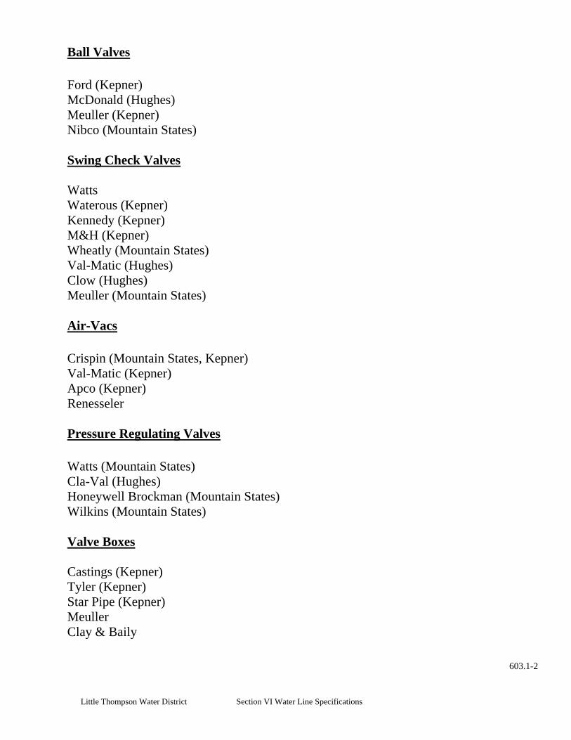
Little Thompson Water District Section VI Water Line Specifications
Ball Valves Ford (Kepner) McDonald (Hughes) Meuller (Kepner) Nibco (Mountain States) Swing Check Valves
Watts
Wheatly (Mountain States)
Waterous (Kepner) Kennedy (Kepner) M&H (Kepner)
Val-Matic (Hughes) Clow (Hughes) Meuller (Mountain States)
Air-Vacs Crispin (Mountain States, Kepner)
Apco (Kepner)
Val-Matic (Kepner)
Renesseler
Pressure Regulating Valves Watts (Mountain States) Cla-Val (Hughes) Honeywell Brockman (Mountain States) Wilkins (Mountain States) Valve Boxes
Castings (Kepner)
Tyler (Kepner) Star Pipe (Kepner) Meuller Clay & Baily
603.1-2

Little Thompson Water District Section VI Water Line Specifications
Fire Hydrants Meuller (Hughes, Mountain States) Waterous (Kepner) Blow-offs
Kupferle (Kepner)
Fittings (PVC) Compression & Slip
Multifittings Corp. (Mountain States, Kepner)
GPK (Mountain States, Kepner)
Spears (Mountain States, Hughes) Colonial (Mountain States) JM Manufacturing (Mountain States) Glasco (Mountain States) Plastic Trends (Mountain States)
Fittings (ductile) Tyler (Kepner) Victaulic Company Of America (Hughes) Grinnell (Mountain States) American Cast Iron Griffin Pipe
U.S. Pipe (Hughes) Fittings (steel)
Pacific States
Ames (Mountain States)
Pierce (Mountain States)
Tapping Saddles & Sleeves, MJ and Stainless
Romac (Hughes, Kepner)
Tyler (Kepner)
603.1-3
Ford (Kepner)
Smith Blair (Kepner)
JCM Ind. (Mountain States, Hughes)

Little Thompson Water District Section VI Water Line Specifications
Mueller (Mountain States) Repair Bands (Stainless Steel)
Powerseal (Mountain States)
Ford (Kepner)
Smith Blair (Kepner) Corporation Stop (brass)
Romac (Kepner, Hughes)
Ford (Kepner) Mueller (Mountain States) McDonald
Service Connection Couplings (brass compression) Ford (Kepner) Mueller (Mountain States) Curb Stops (brass) Ford (Kepner) Mueller (Mountain States) Meter Setters Ford (Kepner) McDonald (Hughes) Meters
Badger (Mountain States)
Sensus (Kepner)
Danfoss
Casing Spacers
Cascade Water Works Powerseal
603.1-4

Little Thompson Water District Section VI Water Line Specifications
Mechanical Joint Restraint
Ebaa (Kepner, Hughes) Flange Adapters & Split Flange Adapters
Ford (Kepner)
Ford, Uniflange (Kepner) Restrained Joint Pipe
U.S. Pipe (Hughes) American (Mountain States)
Service Line, HDPE (2” or smaller)
Phillips Driscopipe (Kepner)
Service Line, Copper (2” or smaller)
Poly Pipe Industries Chevron (Mountain States) CSR Polypipe (Kepner)
Qest (Mountain States) Performance Pipe (Mountain States)
Cerro (Mountain States, Kepner, Hughes)
Mueller (Mountain States)
Halstead (Mountain States)
Reading (Mountain States, Kepner)
Vault Hatches & Steps
Neenah
Comco
Bilco (Aluminum or Painted Steel with Hydraulic Strut)
M.A. Industries
603.1-5

Little Thompson Water District Section VI Water Line Specifications
Meter Pit Dome Castings (Hughes, Kepner) Meter Pit Mid-States (Kepner) DFW (Mountain States) Repair Coupling (Dresser and Transition Couplings)
Romac (Kepner, Hughes)
Ford (Kepner)
Smith Blair (Kepner)
Casing chalks, skids Ford (Kepner)
Cal-Pico (Kepner)
Tracer wire connectors
Double splice- 3m DBY
• No “quick joint” gasket style brass couplings (pak joint and grip joints styles
• No M&H valves
3m waterproof connectors
Triple or quadruple splice- 3m DBR
• Plug style valves or Ball style valves with tee-heads only.
only).
• No Viking Johnson Maxi-Step or Maxi-Fit transition couplings.
603.1-6

Little Thompson Water District Section VI Water Line Specifications

Little Thompson Water District Section VI Water Line Specifications
New Years Day
Labor Day
Thanksgiving Day
Managers Holiday (Day after Thanksgiving)
Christmas Day
Schedule of District Holidays
Martin Luther King, Jrs Birthday
Presidents Day
Memorial Day
Independence Day

Little Thompson Water District Section VI Water Line Specifications
Turn On Fee $ 35.00
Final Read Fee $ 50.00
Return Check Fee $ 25.00
Deposit $ 700.00
Water (per 1,000 gals) $ 2.00
Fire Sprinkler Tap - Commercial up to 6” $ 2,500.00
Fire Hydrant $ 2,000.00
Commitment Letter 2 years
3 - 80 Taps $ 500.00
Plus per lot $ 100.00
Schedule of District Fees
Transfer Fee $ 25.00
Turn On After Hours $ 60.00
Fire Sprinkler Fee $ 50.00
Fire Hydrant Rental
Trip (Inc. P-up & Drop Off) $ 50.00
Meter Rental (1 week minimum; per week) $ 25.00
Fire Sprinkler Tap - Residential $ 1,000.00
Inspection After 5 pm or Holiday & Weekends $ 60.00
0 - 2 Taps $ 100.00
Over 80 Taps (Plus Engineering Fees) $ 500.00 Plan Review
0 - 2 Taps per review $ 25.00 3 - 25 Taps per review $ 50.00 Over 25 Taps per review $ 100.00
Project Inspection & Test $ 300.00

Little Thompson Water District Section VI Water Line Specifications
1otherwise provided in section 24-92-104.
2. An invitation for bids shall be issued and shall include a project description and all contractual terms and conditions applicable to the public project.
3. Adequate public notice of the invitation for bids shall be given at least fourteen days prior to the date set forth therein for the opening of bids, pursuant to rules. Such notice may include publication by electronic online access pursuant to section 24-92-104.5 or in a newspaper of general circulation at least fourteen days prior to bid opening.
4
5
6
7
Construction Bidding for Public Projects Act
. All construction contracts for public projects shall be awarded by competitive sealed bidding except as
. Bids shall be opened publicly in the presence of one or more witnesses at the time and place designated
in the invitation for bids. The amount of each bid and such other relevant information as may be specified by rules, together with the name of each bidder, shall be entered on a record, and the record shall be open to public inspection. After the time of the award, all bids and bid documents shall be open to public inspection in accordance with the provisions of sections 24-72-203 and 24-72-204.
. Bids shall be unconditionally accepted, except as authorized by subsection (7) of this section. Bids shall be evaluated based on the requirements set forth in the invitation for bids, which may include criteria to determine acceptability, such as inspection, testing, quality, workmanship, delivery, and suitability for a particular purpose. Those criteria that will affect the bid price and be considered in the evaluation for award shall be objectively measurable, such as discounts, transportation costs, and total or life-cycle costs.
. Withdrawal of inadvertently erroneous bids before the award may be permitted pursuant to rules if the bidder submits proof of evidentiary value which clearly and convincingly demonstrates that an error was made. Except as otherwise provided by rules, all decisions to permit the withdrawal of bids based on such bid mistakes shall be supported by a written determination made by the responsible officer.
. The contract shall be awarded with reasonable promptness by written notice to the low responsible bidder whose bid meets the requirements and criteria set forth in the invitation for bids. In the event that all bids for a construction project exceeds available funds, as certified by the appropriate fiscal officer, the responsible officer is authorized, in situations where time or economic considerations preclude resolicitation of work of a reduced scope, to negotiate an adjustment of the bid price with the low responsible bidder in order to bring the bid within the amount of available funds; except that the functional specifications integral to completion of the project may not be reduced in scope, taking into account the project plan, design, and specifications and quality of materials.