llqwmntllos - federation of american scientists · mach number exceeds mc. is. ... frameworkwith...
TRANSCRIPT

* LA-UR--84-1391
DE84 011353
cdl=” ?3J@=f=” -A
TITLE: ION REFLECTION, GYRATION, AND DISSIPATION AT SUPERCRITICAL SHOCKS
. .
.. AUTHOR(S): J.T. Gosling and A.E. Robson
SUBMITTED TO: Proceedings of the Napa Shock Conference held in Napa Valley,,CA, 20-24-February 1984
DISCLAIMER
dophlhlmofmltbcmca~hemln dnrtot~luy tibwrowttti orbUnltd Stata oovamnwaitof●y ~ tlmrd
lLQWMNTllOSLosAlamosNewMexico8754gLosAlamos National Laborator
!

ION REFLECTION, GYRATION, AND DISSIPATION AT SUPERCRITICAL SHOCKS
J. T. GoslingUniversity of California
Los Alamos Notional LaboratoryLos Alamos, NM87545
A. E. RobsonNaval Research Laboratory
Washington, DC20375

.---
1. Introduction
Characte~istic changes occur in collisionlese shock structure as the Mach
number of the upstream flow lo Increased above a critical value. A ❑agnetic
foot develops upstream of the main shock ramp, and an overshoot appears at the
top of the rkp. These changea in a shock-s magne~ic profile are closely.,
associated witn the reflection at the shock of a fraction of the incoming ions.
Such reflection plays an important role in ion dis~ipation at high t4achnumber
shocks. The critical Alfv4n Mach number, MC, where ion reflection occurs
depends upon upstream conditions, but typically Mc ~ 2-3. A shock whose ~fv~n
Mach number exceeds Mc IS knowr as a supercritical shock.
The reflection of incident ions IH cauaed by a combination of
electrostatic and magnetic forces and is nearly specular in nature. The
initi~l trajectory of a specularly reflected ion depends crucially cm OBn, the
angle between the upetrecm magnetic field, ~, and the local shock normal, fi.
For 9Bn
guiding
geometry
> 45° (quasi-perpendicular shock) specularly reflected ions have
center motions whi IIare directed downstream. Reflected ions in this
thus return to the shock and gyrate downstream where they contribute
importantly to downstream thermalization. However, for eBn < 45° (qll@18i-
parallel shock) specularly reflected ions gyrate upstream when the upetream
magnetic field ia steady. Thus under,steady upstream condition, rnpaculurly
reflected Ions cannot contribute directly to downccraam tharmalizatlon in tha
quaai-parallel geometry. This fact may be of fundamental importanc~ in
explaining obaafved diffaranceu between quasi-parallel and quaai-perpendicular
ohock atructura. ‘
The purpose of the present paper in to review laboratory ●nd space
meaauremmts pertaining to lniti8i
supercrltical shocks, Us will b,
ion reflection
concornad with
●nd aubacquent gyration at
providing a .Impla conc~ptual,

1 [
-3- .
framework with which such reflection and gyration and its role in producing
dimipation at the shock can be understood. Details of the actual reflection
mechaniam and the relative importance of electrostatic force8 and magnetic
forces in producing ion reflection have b,’enaddressed in considerable depth in
recent simulation studies (e.g., Leroy et al., 1981, 1982) and are reviewed
elsewhere in this volume by Goodrich (1984). Multiple reflections and the
production of a variety of upstream auprathermal ion populations by reflections
and other mechanisms likewiee are treated elsewhere in thie volume by Thomsen
(1984).
2. Laboratory Results
Early space measurements were flufficientto eetablish the ●xistence of
colliaionleea
1964) Ind to
deceleration
and the shape
shocks in the solar wind (e.g., Sonett et al., 1964, Ness et al.,
atudy cerkain macroscopic aapecte of shocks such ae their
‘during outward transit frcm the sun (e.g., Gosling et alp 1968)
of the earth-a bow shock (e.g., Holzer et al., 1966). However,
the measurements (particularly of the plasma) were inadequate to resolve the
structure of the shock layer or to etudy dissipation proceeecs at t“w ~hockm
Stch etudiee became poa~ible in the early 70”e with the launching of improved
plasma instruments aboard later satellite in the Vela, Imp, and C)goseries.
Only relatively recently, however, with the launch of the TSEE-1 and -2
aatellitea have high quality measurements of plasma diatributiona beco~,m
available. Thus much of tha early probing of collisionleaa chock otructura was
concmtrated in laboratory experiment, whoaa prime impetue wae derived from
programa to harneee nuclaar fusion. Funding for ouch experimentrnwae curtailed
in the mid 70-e.

-4-
Laboratory experiments of shocks were done almost exclusively using
e-pinch and Z-pinch devices and were conducted by a variety of groups around
the world. These experiments provided controlled conditions (in contrast to
space measurements) which cculd be repeated. Measuremefits were made of the
magnetic field, ~, the electric potential, ~, the electron densizy, ne,
electron temperature, Te, and bulk flow velocity, V, as functions of position.
In the larger experiments, such as those conducted at the University of Texas
in Austin or at Culham Laboratories in England, the shocks were well separated
(by several ion gyroradii) from the ma~.etic pistons driving them. Further, in
thehe larger experiments the shocks were stationary long enough to permit i
complete ion gyro-orbit downstream. On the other hand, the laboratory
experiments, although collisionless downstream, were not unequivocally
collisionless in the upstream region. Nevertheless, collisionless mechanisms
were necwasary to account for the structure of the observed shocks.
One drawback of the laboratory experiments was that they did not provide
information on the shapes of distribution functions. Nor did they, for the
most part, provide measurements of ions. Mc,stexperiments were done in the
nearly perpendicular geometry (eBn z 900), although oblique geometries were
utilized in some experiments. Paul (1969) and Robson (1969) have provided
excellent reviews of the early laboratory experiments done in the nearly
perpendicular geometry and in the oblique geometry respectively. Here we
provide an extremely limited reviaw of those laboratory results that bear
directly on the problem of ion reflection and di~sipation at supercritical
shocks,
In most experiments it was found that as the Mach
flow was increased, characteristic changes occurred
Figures1, which shows magnetic field and electric
number of the upstream
in shock structure.
potential measurements

-5- .
through two different Mach number shocks, illustrates these changes. ‘When the
upstream Mach number is low (upper panel), both the magnetic field and the
electric potential rise sharply through the shock on a scale size which is
determined by a competition between resistive and dispersive effects (e.g.,
Mellott and Greenstadt, 1984). However, as the upstream Mach number increases
(lower panel), a long foot develops upotream of the main shock ramp when the
shock geometry is nearly perpendicular. (For some reason the foot was not
observed in oblique geometries.) Following the suggestion (e.g., Woods, 1969)
that the foot was caused by reflected’, gyrating ions, experiments were
conducted to detect such ions directly in the nearly perpendicular geometry
(Phillips and Robson, 1972).
Figure 2 illustrates the trajectory of a specularly reflected ion (i.e.,
an ion whose
arbitrary angle
reflected ion”
shock. Because.
normal component of velocity is reversed at the shock) for
of incideoce in the perpendicular geometry (eBn.= 900). The
undergoes a partial gyration about ~ and then re-encounters the
the ion gains energy from the interplanetary ~ x ~ electric
field during the first half of its gyro-orbit, it has sufficient energy upon
reentry into the shock to penetrate into the downstream region. With a
coordinate system fixed in ihe shock as shown in th~ figure, the orbit of the
reflected ion in
Ve‘-y
the upstream region is described by
Cos%wY “ Lv3—[cwimpt .- 1] -Vtsinen
P
(1)
(2)
where Qp = #, V is the Incident flow speed, On is the acute angle between ~P-’
-6-
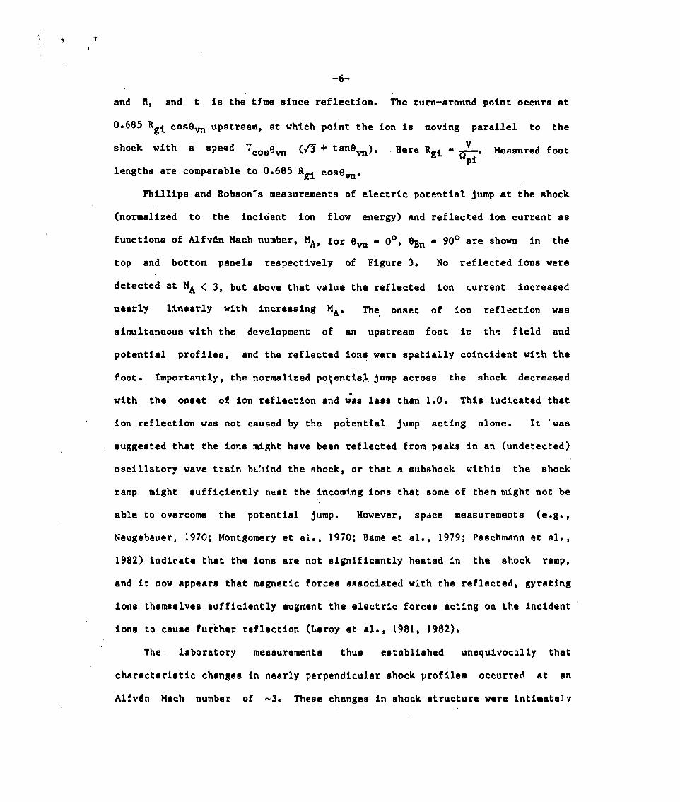
and fl, and t is the tjme since reflection. The turn-around point occurs at
0.685 Rgi Cosen upstream, at which point the ion fS moving parallel. to the
shock with a speed ‘?cosOn (ZJ + tanen). Here Rgi = ~.Qpi
Measured foot
lengths are comparable to 0.685Rgi Cosem.
Phillips and Robson-s measurements of electric potential jump at the shock
(normalized to the incident ion flow energy) and reflected ion current as
functions of A3.fv4nMach number, MA, for en = 0°, eBn = 90° are shown in the
top and bottom panels respectively of Figure 3. No reflected ions were
detected at MA < 3, but above that value the reflected ion current increased
nearly linearly with increasing MA. The, onset of ion reflection was
simultaneous with the development of an upstream foot in the field and
potential profiles, and the reflected ions were spatially coincident with the
foot ● Importantly, the normalized po~entia~.jump across the shock decreased
with the onset of ion reflection and w’aslass than 1.0. This ii~dicatedthat
ion reflection was not caused by the potential jump acting alone. It ‘was
suggested that the ions might have been reflected from peaks in an (undetected)
oscillatory wave tzain b~!~indthe shock, or that a subshock within the shock
ramp might sufficiently heat the,incomtng ions that some of them n~ightnot be
able to overcome the potential jump. However, space measurements (e.g.,
Neugebauer, 1970; Montgomery
1982) indicdte that the ions
et ai,, 1970; Bame et al., 1979; Paschmann et al.,
are not significantly heated in the shock ramp,
and it now appears that magnetic forces associated with the reflected, gyrating
ions themselves sufficiently augment the electric forces acting on the incident
ions to cause further reflection (Leroy et al., 1981, 1982).
The laboratory measurements thus established unequivocally that
characteristic changes in nearly perpendicular shock proflleo occurred at an
Alfvdn Mach number of -3. These changes in shock structure were intimately

-7- “
associated with the onset of Ion reflection at the shock. Hydromagnetic theory
predicts the existence of a critical Mach number, Mc, above which additional
dissipation must occur at the shock (Woods, 1969; Coronitti, 1970). This
critical Mach number occurs when the downstream flow speed normal to the shock
becomes subsonic. For usual laboratory conditions Mc ~ 2.8. As the dispersion
in velocity space resulting from ion reflection represents a significant amount
‘“ofdissipation, it appears that ion reflection is a shock--s chosen way of
achievinq additional dissipation at a
clear why ion reflection,
mode by which additional
available.
3. Space Results
Most of our detailed
su~ercritical “shocks in
bow shock. AS the MA for
rather than
dissipation
information
supercritical shock. It is not presently
some other dissipation process, is the
is achieved. Perhaps it is the only mode
about ion reflection and dissipation at
space plasmas is derived from studies of the Earth-s
the solar wind flow exceeds 4.4 about 95% of the time
(Feldman et al., 1977), the bow shock ON the sunward side of the Earth is
usually supercritical. By way of contrast, most interplanetary shocks
associated with solar activity or high speed stream steepening are subcritical
at lAU. Another difficulty with studies of interplanetary shocks is that they
pass over a spacecraft too quickly for shock structure to be resolved well even
with the best of the present generation of space plasma ~xperiments,
When the first detailed measurements were made near the Earth”s bow shock,
It was discovered that secondary peaks appeared in ion spectra obtained
immediately upstream and downstream of tha shock (Montgomery et al,, 1970;
Formioano and Hedgecock, 1973). It was surmised that thasn eecomlary peako
were associated with ion reflection at the shock and contribv.t~ri~mportantly to

-8-
downstream ion thermalization. However, these early measurements lacked the
temporal and angular resolution necessary to study the problem in depth. Such
studies have become possible using measurements made with the fast plasma
experiments on ISEE-1 and -2, which provide 2-dimensional snapshots of ion
distribution functions in one spacecraft spin of 3 sec (Bame et al., 1978).
The schematic phase space plots in the lower portion of Figure 2
illustrate the positions in velocity space where specularly reflected ions
would be observed at different distances from a perpendicular shock with
arbitrary angle of incidence. It is assumed that the reflected ion orbits are
unimpeded by collective interactions. (The laboratory measurements indicated
little or no collective interactions in the foot’regio..(Phillips and Robson,
1972).) In the plasma rest frame the reflected ions initially have a speed
2 Vcosem. Because an ion-s kinetic energy is conserved in the plasma rest
frame, the reflected ions- subsequent trajectory In velocity space is on a
circle of rad?us 2 Vcosen in the plasma rest frame, As a spacecraft
approaches the shock from the upstream side, reflected ions should first be
observed moving parallel to the shock surface when the spacecraft enters the
foot. The small open circle in the lower left-hand panel of Figure 2 indicates
where the reflected ions would appear in velocity space, At the shock ramp,
reflected ions should appear at two positions in velocity space (middle panel).
The leftmost circle corresponds to ions just recently reflected, while the
other small circle corresponds to ions returning to the shock, having been
reflected earlier at a different shock position.
hand panel), reflected gyrating ions from various
observedsimultaneously at a variety of phases in
Finally downstream (right-
positions along the shock are
their gyro-orbits.

-9- .
Figure 4 shows two ion velocity d,ktributlons obtained on the upstream
side of an ISEE crossing of the bow shock on November 7, 1977. The panels
shown are a small part of much larger sequences for this shock crossing
published previously (Paschmann et al., 1982; Sckopke et al., 1983). Upstream
conditions included a high Mach number (MA = 8.6), a high total plasma ~ (3.9),
and a nearly perpendicular geometry (eBn = 850). The velocity distributions
are presented as contours of equal phase space density? f, in 2-dimensional
velocity space oriented parallel to the ecliptic. The densely packed set of
contours to the right of the + symbol in each panel is the incident,sol.ar wind
beam, while the more widely spaced contours are reflected ions. These
secondary ions first appear at the time shown in the left-hand panel when the
satellite enters the foot of the shock. A more complicated arrangement of
secondary ions is present in the snapshot taken at the shock ramp and shown in
the right-hand panel. Comparison of the positions of the secondary ions in
both panels with the schematic velocity space plots of Figure 2 indicates that
the ions are the result of nearly specuJ.arreflection at the shock. Hcwever,
it is apparent that the
that of the incia,.nt
probably indicates that
thermal spread of the secondary ions is greater than
solar wind. Sckopke et al. (1983) have shown that this
a small fraction of the secondary ions are reflec<ed in
a nonsecular fashion at the shock,
Figure 5 illustrates a similar sequence of measured ion velocity
distributions with emphasis on the downstream regfon for a crossing of the
nearly perpendicular bow shock when MA was relatively low. As the shock speed
past the spacecraft (-100 km s-l) wau relatively high on this occasion, the
reflected ions wete not resolved upstream of the shock. However, immediately
downstream multiple peaks of secondary ions are observed lying approximately on
a circle of radius 2 Vcos@W, as expected if the secondary ions are produced by

-1o-
nearly specular reflection at the shock. The
ions do not maintain their identities for
individual bunches of secondary
long. Frame 4 shows considerably
less structure than Frame 2, and by Frame 6 the secondary ions are dispersed
more or lCMS uniformly around the 2 VCOSen circle. (Breaks in t& contoUr8
occur at low speeds in the spacecraft frame where the count rate approaches
instrument background.)
ion bunches probably is a
Gurgiolo et al., 1983;
Such dispersion in velocity space of
consequence of either kinematical phase
Burgess and S~hwartz, 1984) or ion beam
the secondary
mixing (e.g.,
instabilities
(see Winske, 1984, this volume), and in this example occurs on a spatial scale
of ’12 Rgi (Sckopke et al., 1983).
Jllownstreamion bunches such as those
recognized at . -?Mach number crossings of
numbers, the secondary ion bunches have
.
evident in Figure 5 are most clearly
the bow shock. At higher Mach
higher relative densities and do not
retain their individual identities for as long. In either case, as in the
example shown above, the final downstream distribution generally consists of a
directly transmitted beam of ions which is slowed and deflected at the shock
but not strongly thermalized, plus a high energy shell of secondary ions. Such
distributions are not lkwellians. Figure 6 shows a series of cuts through the
distributions measured downstream of the shock shown in Figure 4. The cuts
were made parallel to the bulk flow direction and begin a few seconds after the
shock creasing. Immediately downstream from the shock the reflected, gyrating
ions are visible as a secondary peak in the spectra. Further downstream the
secondary ions produce a broad shoulder
the.way across the magnetosheath. (This
“diffuse” ions which are often obuerved
energies (Asbridge et al., 1978).) The
at high energies which can persist all
shoulder should not be confused with
downstream of the shock, but at higher
dashed curve after the gap in the
-11- .
sequence $s a Maxwellian fit to the low energy core of the distribution,
helping to emphasize the non-Maxwellian nature of the higher energy ions.
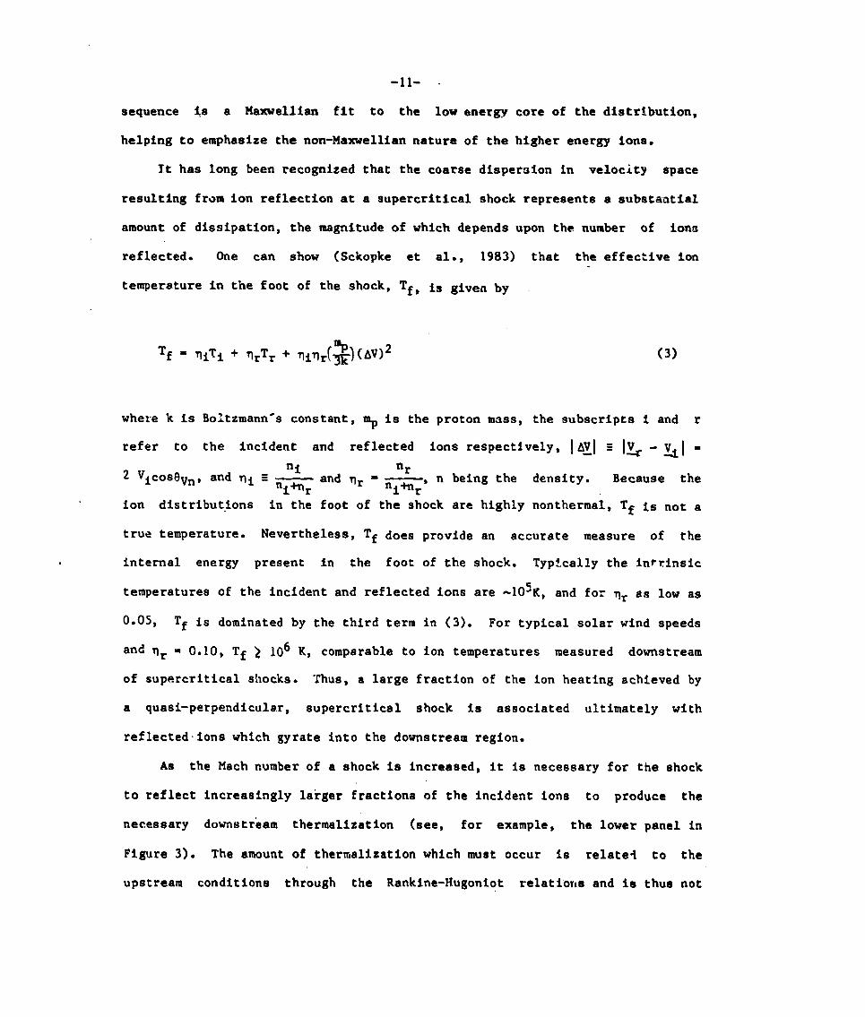
It has long been recognized that the coarse dispersion in velocity space
resulting from ion reflection at a supercritical shock represents a substantial
amount of dissipation, the magnitude of which depends upon the number of ions
reflected. One can show (Sckopke
temperature in the foot of the shock,
Tf = ~iTi + ~rTr + ~iqr[%) (AV)2
et al., 1983) that the effective ion
Tf, is given by
(3)
where k is Boltzmann-s constant, ~ is the proton mass, the subscripts i and r
refer to the incident and reflected ions respectively, lA~l s 1~-VJ=
ni nr2 Vicos8vn, and ni z — and qr
nl*r=—, n being the density. Because the‘i%
ion distributions in the foot of the shock are highly nonthermal, Tf is not a
true temperature. Nevertheless, Tf does provide an accurate measure of the
internal energy present in the foot of the shock. Typ$cally the in?rinsic
temperatures of the incident and reflected ions are -105K, and for qr as low as
0.05, Tf is dominated by the third term in (3). For typical solar wtnd speeds
6 K, comparable to ion temperatures measured downstreamand qr = 0.10, Tf > 10
of supercritical shocks, Thus, a large fraction of the ion heating achieved by
a quasi-perpendicular, supercritical shock is associated ultimately with
reflectedions which gyrate into the downstream region.
As the Mach number of a shock is increased, it is necessary for the shock
to reflect increasingly lakger fractions of the incident ions to produce the
necessary downstream thermallzation (see, for example, the lower panel in
Figure 3). The amount of thermalization which must occur is relatel to the
upstream conditions through the Rankine-Hugoniot relations and is thus not

.
-12-
arbi~rary. UC theref~re expect that the fraction of ions reflected at a
supercritical shock should be predictable from measurements of the upstream
flow. A complication arises due to the fact that the Rankine-Hugoniot
relations determine the combf.nedchange in electron and ion temperatures at the
shock but do not specify how these changes must be subdivided between the two
species (e.g., Sanderson and Uhrig, 1978). Measurements indicate that the
electrons typically heat by a factor of -2.5 at the shock, relatively
independent of shock strength (e.g., Bame et al., 1979). This fact can be used
to derive an expression for t~s downstream ion temperature in terms of upstream
parameters. Equation 3 then allows ‘one to estimate the fraction o: ions
reflected at the shock.
The result of applying the foregoing prescription for two different
upstream plasma temperatures (p -0.1 and 10 respectively) is 6hown fn
Figure 7, where the predicted reflected fraction (nr/ni) is plotted vdrsus
magnetosonic Mach number, Mm8 (Paschmann and Sckopke, 1983). These
calculations suggest that the reflected fraction should not exceed -22% for
typical solar wind conditions; otherwise the downstream temperature hccomes too
large to be consistent with the Rankine-Hugoniot relations. The model
predictions appear to be in reasonable agreement with actual space observations
(the two filled-in symbols) and with thercsults of recent computer simulations
of the perpendicular bow shock by Leroy et al. (1982) (the asterisks).
Thus far wc have assumed that ion reflection at the shock is nearly
specular in nature. This assumption is h reasonable accord with both
laboratory and space measurements already discussed and k?ithsimulation remlta
(e.g., Quest et al., 1983; Leroy and mke, 1983). Specul;r reflection
results because ions are essentially unmagnetized in their interaction with the
shock (e.g., Schwartz at al.$ 1983; Thomsen et al,, 1983). To see this, recall,
.
that typical
‘pi is the ion
-13- ‘
shock thicknesses, AL, are of the order of c/wpt s 100 km, where
plasma frequency (Russell and Greenstadt, 1979). The time for a
salar
speed
for a
tiind parcel
of 400 km S-l
field of 5 nT
to transit the shock, r-, is AL/Vi, which for a solar windLz-c
is 0.2S s. A thermal ion gyroperiod, Tgb is .- which
is -13 s. Thus, a thermal ion experiences only about 2% of
its gyro-orbit as it transits the shock, and so Is essentially unmagnettzed.
during the encounter.
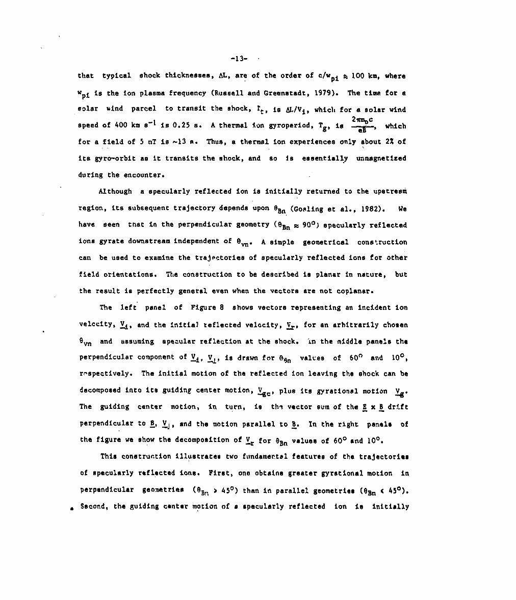
AIthough a specularly reflected ion Is initially returned to the upstremi
region, Its subsequent trajectory depends uPOn eBn (Gosling et al., 1982). We
have seen that in the perpendicular geometry (OBn s 90°) specularly reflected
ions gyrate downstream Independent of On.
can be used to examine the trajectories of
field orientations. The construction to be
A simple geometrical cons~.ruction
specularly reflected ions for other
described is planar In nature, but
the result is perfectly general even when the vectors are not coplanar,
The left” panel of Ftgure 8 shows vectors representing an incident ion
velccity, ~, and the initial reflected velocity, ~, for an arbitrarily chosen
em and assuming specular reflection at the shock. in the middle panels the
perpendicular component of ~, ~, is drawn for @an values of 60° and 10°,
r~spectively. The initial motion of the reflected ion leaving the shock can be
decomposed into ite guiding center motion, V+C) Plus its gyrational motion &.
The guiding center motion, in turn, is th? vector sum of the gx~drift
perpendicular to ~, ~J, and the motion parallel to ~. In the right panels of
the figure we show the decomposition of~r for (+)n values of 60° and 10°.
This construction illustrate two fundamental features of the trajectories
of specularly reflectad ions. First, ono obtaine greater gyratlonal motion in
perpendicular geometries (~Bn > 45°) than in parallel geometries (eBn < 450).
. Second, the guiding center motion of a specularly reflected ion ia initially

-14-
directed downstream for all eBn > 45° but is dtrected upstream for all
eBn < 45°. One can easily shcw in general that
and
* =~ ● n[l - 2(fl● 8)21Ygc”n
(4)
(5)
where 8 is the unit vector along ~ chosen such that B ● h ~ 90°.
The above construction shows that in the ‘absenceof interactions in the
upstream region a specularly reflected ion must return to the shock for
6Bn > 45°. In faCt, fOr a limited range Of eBn values slightly leSS thaa 45°,
a, specularly reflected iones gyrational motion causes it to re-encounter the
shock aven though the guiding center motion is directed upstream. Figure 9,
from Schwartz et al. (1983), shows the result of a calculation of the returning
ion”s velocity perpendicular to the shock at re-encounter normalized to the,
perpendicular componant of the initial incident velocity, Also shown is the
g!rophase (fit*)at the time of re-encounte:. For OBn < 39.9° specularly
reflected ions gyrate upstream anti do not re-encounter the shock. For
39.9° < eBn < 450 the reflected ion”a gyrational motion returns it to the,
shock, but it arrives there with a speed perpendicular to the s!~ockwhich is
leso than it had at its initial encounter. Such an ion probably undergoas
further reflection at
spehd at re-ancounter is
in this geomatry the
downstream region. This
will end up downstream,
the shock. Finally, for OBn > 45° the perpendicular
alwaym greater than at the initial encounter, Thus,
returning ion should panetrate the shock into ths
is not, however, efficient to inaura that tha ion
Simulations and a recent calculation of teot particla

trajectories show that.for
a reflected ion to gyrate
surface (Leroy and Winske,
-“5- ‘
45° < eBn ~ 60°, there are trajectories which allow
back upstzeam after Initial
1983; Burgess and Schwartz,
Measurements made both up and downstream from the
accord with the predictions of the above calculations.
al. (1983) have noted that nearly specularly reflected
penetration of the shock
1984).
earth-e bow shock are in
For example, Sckopke et
ions play an important
role in producing downstream ion thermalization at aupercritical ehockn for all
‘Bn > 45°. Further, ion~ gyrating upstream away from the chock and having
guiding center velocitl.ee and gyrospeeds consistent with specular reflection
have been observed in the quaei-parallel geometry, Figure 10 shows examples of
gyrating ion velocity distributions observed upstream from a crossing of the
quasi-parallel chock (OBn - 370). As in Figurem 4 and 5 the ve:ocity
distributions are presented as contours of equal phaae space density, f, in
2-dimensional velocity space oriented parallel to the ecliptic. The vectors
drawn through” the incident solar wind dietributione represent the ecliptic
projections of the extreme orientation of B maasurad during the 3 s plasma
measurement interval. The bars drawn perpendicular to ~ in each panel provide
a direct comparison with the specular reflection ❑odel, The poeitiona of the
centerrn of theoe bars are the predicted guiding center velocities of the
reflected ions, ●nd their half-lengths are the predicted gyro~peada. These
calculated rnctiontiof tha secondary ions aro in ra6eonably good agreement with
the obeervationa.
We have previously emphasized the vary important role nearly specularly
reflected iono play in producing donstream ion thurmalization at suparcritical
shocks whan eBn > 45°. On the other hand, when eBn ~ 45° naarly sp~cularly
rtflect,d ion. gyrat, back upotraam when tha fiald im ataady ●nd thus cannot
contribute directly to downctr~am thermalization under such condition. How,

-16-
then, Is downstream ion thermalization produced at supercritical shocks in the
qutusi-.parallelgeometry? One possibility is that dissipation in the quasi-
parallel geometry occurs by means other than or in addition to ion reflection
(e.g., Quest et al., 1983). Another possibility is that waves generated by the
backstreaming, reflected ions produce a slowly variable eBn at the shock such
that reflected ions are alternately directed up or downstream depending upon
the instantaneous value of ‘Bn (Gosling et al., 198L). In support of this
suggestion we note Lnat: a) long ~eriod upstream waves appear to be an
intrinsic feature of the quasi-parallel shock (e.g., Greenstadt and Fredricks,
i979); and b) all of the specularly reflected ion events in the quasi-parallel
geometry studied to date are found in cl~se association with such waves
!Tho-en et al”S 1984). Whether ot not the above suggestion has any merit, it
is clear that further studies of the ion reflection phenomenon in :he quasi-
parallel geometry shoul I lead to a better understanding of the eupercritical,
quasi-parallel shock.
To summarize this br{ef review we wi~h to emphasize the following points:
1. Ion reflection 16 the dominant ion di~sipaticm mechanism at nearly
perpendicular, supercritical shocks.
2. An increasing fraction of the ions incident on a bupercritical shock is
refl~cted AS the Mach number incraa@e@. The actual fraction raflacted can
be pradictgd using the Rankine-Hugoniot conservation relations.
3. The effectiva tumparature associated with the diaperaion In velocity opaca
associated with ion reflection accounts for a larga fraction of the
temperature risa oboerved ●crosa supercritical, quasi-perpendicular shocks.

4.
5.
6.
7.
8.
-17- “
Solar wind ions are essentially unmagnetized for single encounters with the
Earth-s bow shock. As a result, ion reflection at the shock is nearly
specular.
!!’hesubsequent trajectory of an ion nearly specularly reflected at the
shock is,.
For eBn
directed
geometry
In the
directly
controlled by oBn.
> 45°, the guiding center motions of a specularly ~eflected ion IS
downstream. Reflected ions returning to the shock in this
should be able to penetrate through the shock.
above geometry, the downstream ion f(v) consists
tranatnitted,slightly heated core population plus a
initially of a
population of
phase-bunched, gyrating ions moving on a circle of radius 2 vi coson.
For 8Bn < 45°, the guiding center motion of a nearly specularly reflected
ion i.sdirected back upetream.
ions cannot contribute directly
Acknowledgement
J. Gosling has collaborated
S. J. Schwartz, N. Sckopke, and M.
When the upstream field is steady, such
to downstream ion thermalization.
closely with W. C. Feldman, C. Paschmann,
F. Thomscn on many of the topics discussed
in this review. He has benefited greatly from their collective wisdom. The
work at Loo Alamos was performed under tl~eauapices of the I)epartmentof Energy
and was supported in part by NASA through the ISEE program (contract number
S-50864A). Work at NRL ,.,,

-18-
Referencea
Aebridge, J. R., S. J. Bame, J. T. Gosling, G. Paachmann, and N. Sckopke,
Energetic plasma ions within the earth-s
Lett., 5, 953-955, 1978.—.
Bame, S. ‘J.,J. R. Asbridge, H. E. Felthauser,
P. Hemmerich, K. Lehmann, and H. Rosenbauer,
magnetosheath,
J. P. Glore,
Geophya. Rea.
G. Paschmann,
ISEE-1 and ISEE-2 fast plasma
experiment and the ISEE-1 solar wind experiment, IEEE Transact. Geosci●
Electron., GE-16, 216, 1978..— —
Bame, S. J., J. R. Asbridge, H. E. Felthauser, J. P. Glore, G. Paachmann,
P. Hemmerich, K. Lehmann, and H. Rosenbauer, High temporal resolution
observations of electron heating at the
75, 1979.
Burgess, D., and S. J. Schwartz, The dynamics
bow shock, Space Sci. Rev.,.—
and upstream distributions
ions reflected at the earth”s bow shock, J. Geo~hys. Res., in press,——
1984.
Coronitti, F. V., Disslpatioa discontinuities in hydromagnetic shock waves, ~
Plaama ~, ~, 26S, 1970.
Feldman, W. C., J. R. Asbridge, S. J. Bame, and J. T. GoslingP Plasma and
magnetic fields from the Sun, in: The Solar Output.— and Its Variation—. —
(O. R. Whita, cd.), PPo 351-382) Boulder) CO (Colorado Associated Univ’
Press), 197/.
Formisano, V., and P. C. Hedgecock, On the rntructure of the turbulent bow
shock, ~ Geop.hya. Rec., 70, 6522, 1973,.
Goodrich, C. C,, Numerical Simulations of Collieionleaa Shocks, this volume.
~ Cooling, J. T., J. R. Asbridge, S. J. Bame, A. J. Hundhausen, and 1~ EC
Strong, Satallite obeervatfons of interplanetary shock waves, ~ Geophys.
Roo., 73, 43, 1968.—.

space structure through gyrophase
1983. “\\
Holzer, R. E., M. G. McLeon, and E. J..
-19- “
Gosling, J. T., M. F, Thomsen, S. J. Bame, W. C. Feldman, G. Paschmann, and
N. Sckopke, Etidence for specularly reflected ions upstream from the qua@i-
parallel bow shock, Geophys. Res. Lett., ~, 1333, 1982..—
Gosling, J. T., M. F. Thomsen, S. J. Bame, and M. Mellott~ Ion and electron
heating at the quasi-parallel bow shock, papet presented at Chapman
Conference on Collisionless Shocks In the Heliosphere, Napa, CA, February
1984.
Greenstaclt,E. W., and R. W. Fredricks, Shock systems in colli~ionless space
plasmas, in Solar System Plasma Physics, Vol. III, edited by L. J.
Lanzerotti, C. F. Kennell, and E. N. Parker, p3, North-Holland,
Amsterdam, 1979.
Gurgiolo, C., G. K. Parks, and B. He Mauk, Upstream gyrophase bunched
ions: a mechanism for creation at the bow shock and the growth of velocity
mixing, ~ Geophys. Ree.,
Smith, Preliminary
Ogo 1 search coil magnetometer: boundary positions
spectra, ~ Geophys. Res., 71, 1481, 1966..—
Leroy, M. M., and D. W1.nske,Backstreaming ions from oblique
Ann. Geophys., ~, 527, 1983.
reslllts
88, 9093,
from the
and magnetic noise
Earth bow shocks,
Leroy, M. M., C. C. Goodrich, D. Winske, C. S. Wu, and K. Papadopoulos,
Simulation of a perpendicular bow shock, Geophys. Res, Lett., ~, 1269,
1981.
Leroyt M. M., D, Winske, C. C. Goodrich, C. S. Wu, and K. Papadopoulos, The
structure of p,arpendicularbow shocks, J._ Gaophya. Ree., 87P \081, 1982.
-20-
Livesey, W. A., C. F. Kennel, and C. T. Russell, ISEE-1 and -? observations
of magnetic field strength overshoots in quasi-perpendicular bow shocks,
Geophys.
Mellott, M.,
shocks:
Res. Lett., 9, 1037, 1982.—— -
and E. W. Greenstadt, The structure of oblique subcritical bow
ISEE 1 and 2 observations, ~ Geophys. Res., 89, 2151, 1984.
Montgomery, M. D., J. R. Asbridge, and S. J. Bame, Vela 4 plasma observations
.x .&Y%— —near the earth-s bow shock, J. Res., 75, 1217, 1970.
Ness, N. F., C. S. Scarce, and J. B. Seek, Initial results on the IMP 1
magnetic field experiment, ~ Geophys. Rea., 69, 3531, 1964.——
Neugebauer, M., Initial deceleration of solar wind positive ions in the Earth”s
bow shock, ~ Geophys. Res., 7S, 717, 1970.
Paschmann, G., and N. Sckopke, Ion reflection and heating at the earth-s bow
shock, in Topics in Plasma-, Astro-, Space Physics, p. 139, .dited by
G. Haerendel and B. Battrick, MPI fUr Physik und Astrophysik, 8046
Garching, W. Germany.
Paschmann, G., N. Sckopke, S. J. Bame, and J. T. Gosling, Observations of
gyrating ions in the foot of the nearly perpendicular bow shock, Geophys.
Rea. Lett., ~, 881, 1982.— —.
Paul, J. W. M., Review of experimental studies of coilisionless shocks
pr~pagating perpendicular to a magnetic field, in Collialon-Free Shocks in.— .
~Laboretoty and Space, ESROSP-51, p. 97, 1969.
Paul, J. W. M., L, S. Holmes,M. J. Parkinoon, and J. Sheffield, Experimental
obeervationo on the structuro of collisionless shock waves in a magnetized
plasma, Nature, 208, 133, 1965.—— —
PhillipcD P, E., A study of the structura of collieionlesa chuck waves
propagating perpendicular to an initial field, Thes~e, Physice Depertmen$,
T~Q University af Texae, December 1971.

.
-21- .
Phillips, l!.E., and A. E. Robson, Influence
structure of a collistonless shock front,
of reflected ions m the magnetic
E!9!e&s!!L LettC, Q, 154,
1972.
Queet, K. B.,
dissipation
471, 1983.
Robsov A. E.,
D. W. Forslund, J. U. Brackbill, and K.
pr~cesses in quasi-parallel shocks, Geophys.
Lee, Collisionless
Res. Lett., lC,—— —
Experiments on oblique shock wavee, in Colltsicfi-TreeShocks in—— -— —
the Laboratory and Space, ESRO SP-51, p. 159, 1969.
Russell, C. T., and E. W. Greenstadt, Initial ISEE magnetometer
results: Shock observations, Space Sci. Rev., 23, 3, 1979.——
Sanderson, J. J., and R. As Uhrig, Extended Rankine-Hugoniut relatione for
collisionless shockss J. Geophys. Res., 83, 1395, 1978.—.
Schwartz, S. J., M. F. Thomsen, and JS T- Gosling, Ions upstream of the
earth-e bow shock: a theoretical comparison of alternative source
population”a, ~ Geophys. Ree., 2039, 1983.
Sckopke, N., G. Paschmann, S. J. Bame, J. T. Gosling, and C. T. Russall,
Evolution of ion distribution across the nearly perpendicular bow
shock: $pecularly and non-specularly reflected-gyrating ions, ~ Geophys.
Rcs,, 88, 6121, 1S83.——
Sonett, C, P., D. S. Colburn, L. Davis, E. J. Smith,
Evidence for a collision-free magnetohydrodynamic shock
apace, Phys. Rev, Lett, 13, 153, 1964..—
and F. J. Coleman,
in interplanetary
Thomsen, M. F., Suprathermal ions
volume, 1984.
Thonwen, M. F., S. J. Schwartz, and
the origin of lone upstream of
88, 7843, 1983.
upstream of the earth’s bow shock~ this
J. T. Gosling,
the earth”s bow
Observational evidence on
shock, J. Gethys, keg ,—— —.

-22-
Thomeen, M. F., J. T. Gosling, S. JO Bame, and C. T. Russell, Gyrsting ions
and large-amplitude, monochromatic MHD waves upstream of the earth-s bow
shock, & Geophys.
Wineke, D.. Micrctheory
1984.
Res., submitted, 1984.
of collislonless shock current layers, this volume,
Woods, L. C., On the structure of colli~fonless magneto-plasma shock waves at
supercritical Alfv4n-Mach numbe’ ?l&sma Phys., ~, 435, 1969.
~u. captions
Figure 1. Magnetic field and electric potential profiles of a subcritical
shock (upper panel) and a supercritical shock (lower panel) for oBn - 90°
(from Paul et al., 1965). For MA ~ 3, a foot of length 0.7 Rgi developz
upstream of the main shock ramp. Here Rgi is an ion gyroradius for,a
particle with speed equal to the shock speed through the ambient plasma. A
small overshoot in the potential occurs at the back of the shock ramp in
the supercritical regime. Similar overshoots in ~ and electron pressure
are commonly observed at the Earth”s bow shock (e.g.) Livesey et al.~ 1982;
Bame et al., 1979).
Figure 2a. Idealized sketch of the trajectory of an ion specularly reflected
off a planar shock with eBn = 906 for arbitrary angls of incidence.
b. Tdealizad 2-dimensional Ion velocity distributions resulting from
specular reflection at several distances from the shock ramp. The
reflected particles mova in velocity space along a circle of radius
2 VCOS9m ccntgred
the orientation of
at the bulk flow velocity. The dashed lines indicate
the shock surfaca.

-23- .
Figure 3. .Slectricpotential jump at the shock (upper panel) and reflected ion
current (lower panel) as functions of MA for 6Bn = 900. lhe potential jump
is nonualized to the incident Ion ‘flowenergy (from Phillips, 1971).
Figure 4. Iorivelocity distributions obtained during an inward crossing of the
Earth-s bow shock. Each panel represents a 3 sec snapshot of f(v) obtained
at the locations indicated by the dots on the electron density profiles
shown as inserts. The distributions are shown as. contours of constant
phase space density separated logarithmically in 2-dimensional velocity
space, where one of the axes points toward the sun on the left, and the +
symbol indicates zer~ speed in the spacecraft frame. The dashed lines
indicate the orientation of the shock
1983).
Figure 5. Ion velocity distributions
surface (from Paschmann and Sckopke,
obtained downstream of a marginally
supercritical shock with
the measurement plane of
except that more contour
eBn s ~ooand ~ oriented nearly perpendicular to
the instrument. The format is similar to Figure 4
levels are shown. The dashed circle in the second
frame indicates the expected locus of specularly reflected ions in the
downstream region (from Sckopke et al., 1983).
Figure 6. Time sequence of l-dimensional ion distributions downstream of the
shock crossing shown in Figure 4, The cuts were made in the direction of
the bulk flow. Units for energy are in keV, and f is in units of cm6 S-3
(from Sckopke et al., 1983).
Figure 7. Theoretically predicted ion reflectivity of the bow shock as a
function of magnetosonic Mach number. The two curves refer to different
upstream temperatures corresponding to Pi - 0.1 and 10, respectively. ThQ
filled-in symbols are spacecraft measured valuas, and the asterisks

-24-
indicate values obtained from numerical simulation studies (from Paschmann
and Sckopke, 1983).
Figure 8. A series of planar vector diagrams illustrating the guiding center
velocity, &c, and gyrattonal motion 1~1 resulting from specular
reflection of an Ion initially fncident on a supercritlcal shock with the
plasma bulk flow velocity, ~ The inttial, in different 8Bn geometries.
reflected veloclty, ~, is obtained by reversing the normal component of
~. Note that the reflected ion must have the same ~x B_drift, ~, as the
incident plasma flow.
Figure 9. Gyrophase angle (S2t*)and normal ve,locity(v~(t*)), in units cf the
normal component of the incident flow velocity, ~) of a specularly
reflected ion at the time of re-encounter with the shock, t*, as a function
of OBn (from Schwartz et al,, 1983).
Figure 10. Ion velocity distributions obtained upstream from the bow shock for.,-----------
eBn~ 370 and ~ nearly in the measurement plane of the instrument. ‘The
format Is similar to Figures 4 and 5. Tic marks and numbers in the lower
right of each panel indicate the velocity scale in km S-l. The extreme
orientations of the magnetic field vector within each 3 s measurement
Interval are indicated by the vectors~~, ~drawn through the center of
the incident solar
indicate the expected
ions (from Gosling et
wind. The ends of the bars drawn perpendicular to ~
positions in velocity space of specularly reflected
al., 1982).

v, Qolti)Bz-BzQ(kG)2.0
I.0
M,= ?5
“ 6;.= 1.2kG6z-Bz~d.
y~ = 24x 10’cmitc,/
/
—
}00
200’
100
-20 0 20 40
TIME (n SCC)

.,
,-
Vy
UPSTREAM SWCK RAMP

0.5
1.0
1.0
I 2345MA
123456MA

I SEE 2 7 NOV 1977
l-’”’{
500 KM/s
/
‘Q)Q/
/
/
/
22:51:01
/
/
/
22:51:37

~.... :. . ...... . .
+ ai$i)l&8u21s
Y%--
149C0101
148*37
14103s X3
-F=&-
25[
14J1OSO1 /

,;
*
::,,“‘
10-21
F 10“~
10“2s
10-27
mGY -
9...,!

-’
,- E
v1.
2
*
3
J I 1 f I I I 1 I I I I
6 e

.
*
Vr
SHOCK
IIII
IIIiI1I
s. Iv %’
---9 ‘+?c1
‘>, 1/,0
I
P.. ‘)

.
240
60
20
I.
,
I I I I40 60 80
1.5
I*“
u
-c>
05●
●9-
‘B” (deg)
..

ISEE-2 AUGUST15. 1978
I f-{
1222:59,8- 1223:02,4 UT
R. &
1223:3Ss8 -38,4 UT