lng fuelled perfect - dnvgl.com tech würsig_2015-10_web_tcm8... · using a two stage pressure...
TRANSCRIPT

1
1 SUMMARY
GTT, CMA CGM and its subsidiary CMA Ships and DNV GL studied the technical design and economic feasibility for an electric-driven 20,000 TEU ULCV vessel with an LNG-fuelled combined cycle gas and steam turbine (COGAS) electric power plant
The ship, equipped with LNG membrane tanks for one full Asia – Europe return voyage, was benchmarked against a conventional HFO-fuelled vessel featuring the same hull shape and operating in the same trade. The high-level study addresses the technical feasibility and overall fuel efficiency, and includes a preliminary economic assessment.
The study shows considerable benefits due to capacity gains at the same efficiency level. It demonstrates that the use of the clean LNG fuel has significant efficiency benefits which cannot be achieved by a conventional-fuelled COGAS system. The potential for an optimized LNG-fuelled COGAS system goes even beyond the efficiency of the oil-fuelled engine systems used today. At the same time, cargo capacity is increased by the use of LNG and not decreased as is the case for LNG-fuelled piston engine systems. In fact, the cargo capacity is higher than the capacity of a conventional oil-fuelled ship of the same size. This is the result of placing the COGAS system at deck level within the area of the deck house and the LNG tanks. Therefore, nearly the complete space normally occupied by the engine room and the funnel structure can be used for cargo.
The electric power generation allows the power plant to be split from the propulsion motors. For this reason, a conventional engine room is not needed any more. In addition, the three electric main motors, which are arranged on one common shaft, can run fully independently from each other, providing increased redundancy and reliability.
With gas-turbine-driven power production, utilizing a very clean fuel and with electric propulsion, the ship’s machinery systems are simplified and made much more robust. It is expected that this approach can lead to new maintenance strategies as found in the airline industry, which may make it possible to reduce the ship’s engine crew, leading to further cost savings.
LNG fuelled PERFECt Piston Engine Room Free Efficient Containership
2
Optimizing the power plant by minimizing the steam turbine size, reducing power capacities, condenser cooling, using a two stage pressure steam turbine and steam generator will increase the system’s efficiency further. The net efficiency is expected to be well above conventional-fuelled piston engine ships.
In a next step, the project partners GTT, CMA CGM and its subsidiary CMA Ships and DNV GL intend to work on the optimization of the power supply system and of the overall ship design.
2 BACKGROUND
LNG as a fuel is the ideal fuel for gas turbines. By using this clean fuel, the turbine inlet temperatures and, as a consequence, the turbine efficiency can be increased compared to turbines fuelled with conventional ship fuel. At the same time, the turbine outlet temperature increases as well and allows for the installation of high-efficient steam turbine cycles which use the turbine exhaust gas.
For these reasons, COmbined Gas and Steam turbine (COGAS) power generation today is the most efficient and economical way to convert fuel into mechanical power or electricity. Modern stationary COGAS plants running on natural gas achieve net plant efficiencies of approx. 60%. This value cannot be reached by conventional diesel engines of ships where the engine efficiency is known to be around 52%.
The high power density and the modularity of COGAS plants, together with the electric propulsion concepts, lead to additional container slots. This makes up for the slots which are lost by the higher space requirements for LNG as fuel compared to HFO as fuel.
The trend towards increasing size and relatively high design speeds of container ships leads to a high power demand of these ships. This high power demand allows COGAS plants of high efficiencies which can be expected to be competitive with conventional-fuelled 2-stroke diesel engine systems.
For these reasons, GTT, CMA CGM and its subsidiary CMA Ships and DNV GL decided to have a closer look to the COGAS technology applied to container ships to determine the feasibility of such systems.
3 THE REFERENCE SHIP
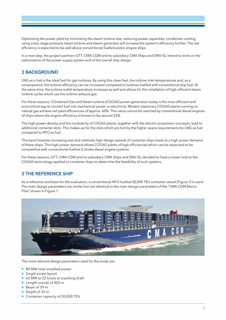
As a reference and base for the evaluation, a conventional HFO-fuelled 20,000 TEU container vessel (Figure 1) is used. The main design parameters are similar but not identical to the main design parameters of the “CMA CGM Marco Polo” shown in Figure 1.
The most relevant design parameters used for the study are:
� 80 MW total installed power � Single screw layout � 65 MW at 22 knots at scantling draft � Length overall of 400 m � Beam of 59 m � Depth of 33 m � Container capacity of 20,000 TEU

3
The analysis of overall ship efficiency and fuel consumption is based on an Asia – Europe return voyage using the real profile and including all port calls (Figure 2).
Figure 2: Operational profile for the ship
The operational profile of the ship for the leg is shown in Figure 2. It demonstrates the chronological order of the ship’s electric power demand, including sea, manoeuvre and port operation modes.
The power demand of the ship is also based on real data (Figure 3 and Figure 4).
Figure 3: Histogram of the main engine’s operational profile Figure 4: Histogram of the auxiliary engines’ operational profile
The electric power demand for the leg varies widely as a result of varying ship speeds between the single ports and the different numbers of reefer containers carried. And, of course, there is a big difference between the power demand at sea, which reaches values of more than 50 MW, and the power demand in port, at less than 5 MW. This also becomes obvious by the histograms in Figure 3 and Figure 4, representing the ranges and the frequency of the required propulsion power and auxiliary power demand of the ship throughout the leg.
In addition to the power demand of the ship, it is important to consider the ambient conditions when designing a propulsion concept. The ambient conditions affect the performance of a powering system, especially that of a gas turbine. For the main sea areas of the leg, the ambient conditions air temperature, relative humidity and sea water temperature are used for summer and winter seasons.
0,0 0,2 0,01,8
20,9
29,1
13,812,1
22,1
0,000
5
10
15
20
25
30
35
0-55 -101 0-15 15-202 0-25 25-303 0-35 35-404 0-45 45-505 0-55Propulsion power at sea [MW]
Rot77j & Rot84j
0,00 0,0
32,7
40,6
0,0 0,5 1,0
25,2
0,00
5
10
15
20
25
30
35
40
45
2,0 - 2,22 ,2 - 2,4 2,4 - 2,62 ,6 - 2,8 2,8 - 3,03 ,0 - 3,2 3,2 - 3,43 ,4 - 3,6Aux power at sea [MW]
Rot77j & Rot84j

4
For the conventional-fuelled reference ship, a scrubber system was assumed. The comparison of both designs is based on the total fuel consumption during the two-way voyage. The different operation modes, power demands, efficiencies in part load, operation of auxiliary engines, etc. were considered.
The final result showed that the overall efficiency of the COGAS system and that of the HFO-fuelled 2-stroke engine system are very close to each other. It has to be considered that the COGAS system chosen for the feasibility study is not finally optimized. There is still efficiency potential, for instance by:
� minimizing the steam turbine size to increase efficiency, � reducing power capacities to run the system closer to the optimal efficiency, � optimizing the condenser cooling of the steam turbine to increase steam turbine efficiency, and � using a two-stage pressure steam turbine and steam generator instead of the single-stage turbines used in the
feasibility study. It is expected that the net efficiency of the COGAS system will be well above the efficiency of the conventional system. Additional gains in efficiency are expected by optimizing the ship design and taking advantage of the flexibility related to the “missing” engine room.
4 THE PERFECt SHIP
All power consumers are electrically driven. The electrical propulsion concept of the design allows for the decoupling of the power generation by generator sets from the power supply to the propeller by electrical motors. As a consequence, a conventional engine room is not needed and additional container slots are provided. Figure 5 shows the general arrangement of the ship.
Figure 5: General arrangement of the PERFECt ship
The following main design aspects are considered:
Power distribution The aim is to provide a minimum number of power generating sets (or gen-sets), most of them being identical and all of them able to run in parallel in load sharing mode. This allows for the higher load of operation of the gen-sets during operating modes with small power requirements, which effectively increases the system’s efficiency.
The advantage of having identical gen-sets is mainly related to cost savings for maintenance (consumable, management of spare parts, etc.), the training of crew and adjustment of parameters in the various running modes.
Number, type and capacity of gen-setsThe electrical power generation is adapted to the required power demand and considers the operating profile of the ship.
Dynamics in the power demand of the shipThe architecture of the power-generating system considers the fast reaction time needed to increase or decrease the power even when such changes occur abruptly.
LNG tankSB
LNGtanks
Bosun store
Void
Void
Steering gearroom
Void
Chain locker
Bowthruster room
Aft peakvoid
Void
SLWL
A.P
Profile
Main deck(+30200 mm / OH)
Second deck(+23312 mm / OH)
Second deck
Main deck 30200/OH
A deck 38200 / OH
B deck 41800 / OH
D deck 49400 / OH
E deck 53200 / OH
F deck 57000 / OH
G deck 60800 / OHTop of wheelhouse deck
C deck 45600 / OH
2600/OH
3100/OH
7778/OH
5189/OH
Propulsion room
Aft mooringstation
Fore mooringstation
Main particulars :LOA: 400 mBeam: 59 mDepth: 30.2 mDesign speed 20 knotsTEU Capacity: approx. 20,400
Transerval sectionframe 47-54
FWtank
Passageway
Passageway
FWtank
BW BW
fr 7975
fr 72
Passageway
Passageway
FWFW
SLWL
Passageway
Passageway
FWFW
fr 72
fr 68
Transerval sectionframe 68-72
Transerval sectionframe 72-79
BW BW
Passageway
Passageway
FWFW
BW BW
V
Transerval sectionframe 86
V
LNG tankPS
B deck
LNG tankPS
LNG tankSB
Switchboardroom
ECR
10 20 30 40 50 60 70 80 90 100 110 120 130 140 150 160 170 180 190 200 220 230 240 250 260 270 280 290 300 310 320 330 340 350 360 370 380 390 400 410 420 430 440 450 460 470 480 490 50010200 mm 12600 mm 2100 mm12600 mm 2100 mm12600 mm 2100 mm12600 mm 2100 mm12600 mm 2100 mm12600 mm 2100 mm12600 mm 2100 mm12600 mm 2100 mm12600 mm 2100 mm12600 mm 2100 mm12600 mm 2100 mm12600 mm 2100 mm12600 mm 2100 mm12600 mm 2100 mm 20700 mm 12600 mm 2100 mm12600 mm 2100 mm12600 mm 2100 mm12600 mm 2100 mm12600 mm 2100 mm12600 mm 2100 mm12600 mm 2100 mm12600 mm 2100 mm12600 mm 2100 mm
Container hold 1Container hold 2Container hold 3Container hold 4Container hold 5Container hold 5Container hold 6Container hold 7Container hold 8Container hold 9Container hold 10
10 20 30 40 50 60 70 80 90 100 110 120 130 140 150 160 170 180 190 200 220 230 240 250 260 270 280 290 300 310 320 330 340 350 360 370 380 390 400 410 420 430 440 450 460 470 480 490 5000
10 20 30 40 50 60 70 80 90 100 110 120 130 140 150 160 170 180 190 200 220 230 240 250 260 270 280 290 300 310 320 330 340 350 360 370 380 390 400 410 420 430 440 450 460 470 480 490 5000
10 20 30 40 50 60 70 80 90 1000
SGT400
A deck
FGHS room
Steam turbine25 MW
2.7 MW genset
4.1 MW genset
Steamturbine
Steam turbine25 MW
Steamturbine
Rev 0: initial versionRev 1: Updated after client’s remarks
Preliminary general arrangement plan VG
Page1/1
Document n°Projet n°
Echelle Taille
A0
7, rue Alfred Stevens75009 ParisFrance
Tel / Fax: +33 (0)9 84 67 41 67Email: [email protected]
24/03/15Date
2015/06 100
1/800
ASSISTANCEMARINE
1RevCOGES ULCV

5
5 COGAS SYSTEM SIMULATION
For the evaluation of the COGAS system, the chosen layout is modelled and simulated in DNV GL COSSMOS simulation software. A detailed model of the system is developed and calibrated using validated data. A simplified representation of the model is shown in Figure 6.
Figure 6: Piping and instrumentation diagram of COSSMOS model (209 components // 4,048 non-linear equations)
The model consists of 209 components (main and auxiliary) counting for 4,048 non-linear equations. The key system aspects that were considered for the simulation are reflected in Figure 7.
Figure 7: Modelling aspects of the COSSMOS model
Operating Profiles
Propulsion � Speed � Power
Fuel compression
Fuel management Prime movers Auxiliary
EnginesPower
Management
Electricity � Total � “Parasitic”
LNG � Natural � Forced
Modes � Hours � Mission legs
Ambient temperatures
Technology � LNG pumps � Vaporisers
Glycol systems
Inlet air cooling
Mass balance logic
NBOG / FBOG mixing
LHV to engines
Flow to GCU
Selection
Modelling
Heat recovery
Combined cycle units
Selection
Modelling
Equal load sharing
Units in operation
Link with gas management

6
One of the main challenges for the simulation – pointing out the strength of COSSMOS – is the high complexity and dependency among all components. For example, the power generation of the gas turbine and the power generation of the steam turbine depend on each other, which has to be considered for the simulation. For a given power demand, the starting point of iteration has to assume a certain load of the gas turbines, while the rest of the power needs to be provided by the steam turbines. The produced power of the steam turbines, however, depends on the exhaust gas parameters of the gas turbines which are the power source for the steam generator of the steam turbines.
If the steam turbine cannot match the power demand, the gas turbine load must be increased; exhaust gas parameters and mass flow change accordingly until the power of steam and gas systems is balanced and the actual demand of the ship propulsion, hotel load, auxiliary and cargo demand is met.
The balanced operational condition defines the LNG consumption of the gas turbines, thus determining the required heating demand for LNG vaporization. As this is applied for the intake air cooling of the gas turbines, this again affects the gas turbine power, hence balance of load sharing. The principle is the same for the changed demand in electricity for cytogenetic pumps for LNG treatment, etc. This line could be further drawn through all components in the complex system.
6 LNG STORAGE IN MEMBRANE TANKS
Two membrane fuel tanks with a geometrical capacity of 10,960 m³ each (100% volume) are used for LNG storage. The tanks are of GTT’s Mark III Flex design. Figure 8 shows the principle of the insulation system and Figure 9 shows a Mark III tank installed on an LNG carrier. This design ensures safe operation under all weather conditions and at all filling levels, high thermal performance and high volume utilization. The tanks are located near the midship section below the superstructure. The size of the tanks is approximately twice the size of an HFO tank with similar energy content.
Figure 8: Mark III principle of the insulation system Figure 9: Mark III tank installed on an LNG carrier
The space above the tanks is sufficient for the installation of the COGAS system and the accommodation, hence no engine room is needed at the aft of the vessel (see general arrangement plan in Figure 5). As a result, the ship gains approx. 300 container slots compared to the HFO-fuelled reference ship.

7
7 GLOBAL STRENGTH
Without an aft engine room island, the question of global strength had to be evaluated to decide on the feasibility of the concept.
DNV GL performed the global strength analysis based on a generic standard container ship design of about 20,000 TEU. This design was modified in the aft part by removing the machinery room and decks and adding lower engine room decks for the electric propulsion machinery space. On top of the deck, container spaces were considered within the hold. Additionally, main engine foundations have been replaced by smaller foundations for the electric propulsion engines (Figure 10).
Figure 10: Finite element model of the aft ship (PERFECt project)
Both designs – the generic standard design and the simplified alternative design – are analysed with finite elements with respect to
� hatch opening deflections and movements, � stress evaluation of the whole vessel, and � hatch corner fatigue.
The modified design will have to be reinforced at several local positions. This is mainly due to the reduced torsional stiffness of the new aft ship without the stiffening engine room construction. Within the scope of the study it was qualitatively judged if the modified aft ship creates major problems regarding the ship’s strength. No fundamental show-stoppers have been identified.
The diagonal hatch opening deflections resulted in higher – but controllable – values.
Maximum hatch cover movements rose and therefore the affected holds require a modified hatch cover design (e.g. five-cover design) or a stiffer hull construction.
At midship areas, the strength limit was partly exceeded; buckling in the inner and outer bottoms is possible. Here the moment of inertia would need to be increased or the plate thickness in the critical regions must be increased.
Some container benches in the aft and the new propulsion engine room need reinforcement.

8
Finally, the hatch corner fatigue was investigated. DNV GL calculated all corners within the vessel. Results showed that all but one corner could be controlled by maintaining radius and adding plate thicknesses. The most critical corner was on the upper deck where the support of the removed main engine room deck is lacking. Here a keyhole or alternative solution would be required in the design.
In summary, the required modifications are mainly based on the fact that the study was based on dimensioning of the conventional two-island design with less torsional deformation in the aft part. The higher torsional deflection of the hull generates higher stresses in some locations, requiring adjusted scantlings. As an alternative solution to stiffening, for some bays a five-part cover could be considered. The additional steel works on the hull were considered, changing the hull costs only marginally.
8 CAPEX AND OPEX
For the cost–benefit assessment, investment costs of the PERFECt LNG-fuelled ship were compared to the conventional-propelled ship. Within the analysis, costs for additional and reduced systems to the base case where considered.
This includes additional costs for, among others,
� membrane tanks, � gas and steam turbines, � fuel gas handling, and � structural reinforcements (no aft engine casing).
Some costs can be compared to the 2-stroke engine system. These are, among others,
� scrubber, which is eliminated, � cooling system capacity, which is reduced and the system simplified, and � HFO treatment or tank heating, which is not needed.
At the end, the CAPEX for the COGAS ship are regarded to be 20% to 24% above a conventional-fuelled vessel.
The OPEX costs largely depend on the difference in fuel price, the additional income related to the additional containers which can be transported and the savings related to a possibly higher system efficiency.
Currently, the gas price in Europe on the spot market is nearly the same as the HFO price (as of 19 October 2015; IFO 380: 6.59 $/mmBTU = 253 $/t; Gas TTF: 6.85 $/mmBTU [lhv]). In a developed market, the distribution costs may be around 2 $/mmBTU. A business case using HFO plus scrubber as a reference therefore needs compensation either by a larger difference between gas and LNG price or by additional benefits from efficiency improvement and additional revenue from additional container slots.
The results of the feasibility study, including the CAPEX and OPEX calculations, encourage the partners GTT, CMA CGM and its subsidiary CMA Ships and DNV GL to plan a more detailed evaluation of the overall system in a follow-up project.
CONTACT
GTT: [email protected]
CMA CGM: [email protected]
DNV GL: [email protected]
DNV GL – Maritime, Brooktorkai 18, 20457 Hamburg, Germany. Phone: +49 40 36149 7800. [email protected] www.dnvgl.com/maritime © DNV GL 10/2015 Design: Maritime Communications