load balancing algorithm exploiting overlay techniques
TRANSCRIPT

Load Balancing Algorithm Exploiting Overlay
Techniques
Anton Dort-Golts, Olga Simonina
Networks Department, State University of Telecommunications, Saint-Petersburg, Russia
[email protected], [email protected]
Abstract — In the article we propose network traffic load
balancing mechanism, based on the identification of a single
network- or transport-layer traffic flows. The principal idea of
proposed algorithm is a dynamical observation of the
distribution router links current load, with such routers
combined in special overlay network. For the purpose of load
balancing some single flows after reaching load threshold could
be relocated to alternative routes. Proposed algorithm is able to
make selective flows relocation taking into account QoS demands
of each single flow.
Keywords— load balancing, P2P, overlay networks, traffic
engineering, QoS
I. INTRODUCTION
Urgency of this research is caused by irregularity of traffic
loads aroused on the access layer by ISP`s different segments
users. It is known, that traffic load correlations with time of
the day, subscriber`s age, area of interests and familiarity of
up-to-date Internet-technologies could be observed [1].
Techniques, that are employed today to estimate the
bandwidth of distribution-level router links, commonly use
reducing coefficients, i.e. expect channel utilization not higher
than some value [2]. But they don`t take into account impact
of traffic burstiness, irregular distribution of the subscribers at
the given moment and L3-VPN usage caused to ensure QoS
demands. Current load balancing mechanisms utilize routing
protocols capabilities and take into account channel bandwidth
or /and DSCP field value of single IP-packets. But when we
try to introduce NGN services there is a necessity of certain
flows relocation occurs. This is caused by channel switching
emulation on the network layer and representing traffic of
different services, especially streaming ones (online-video, IP-
telephony, conferencing) as a variable bitrate channels.
Proposed algorithm employs load balancing mechanisms,
based on the overlay networks and permits to redirect flows
selectively, taking into account QoS demands of each certain
flow. It is supposed that such algorithm could be used on any
layers performing routing functions.
II. RELATED WORK
Attempts to efficiently redistribute packet network traffic
has been making since the appearance of routing in ARPANet.
This research area has its own name – Traffic Engineering
(TE). First trend of traffic load optimization was MPLS-TE
[3], allowing to balance traffic on the channel-layer (L2).
Network-layer support of TE methods for the popular routing
protocols, such as OSPF and IS-IS, was proposed as an
extension of the protocols [4]-[5]. There are also hybrid
solutions, such as [6], trying to combine and harmonize
routing on both levels: MLPS and OSPF. All this mentioned
approaches are used to be called ―offline‖-methods, and their
key drawback is preliminary alternative routes computation
based on the long-term averaged network load information.
The consequence of such an approach is impossibility to
adequately react to the momentary traffic bursts, which cannot
be predicted, raised by BGP reroutes, flash crowds, attacks etc.
To eliminate these drawbacks there were some ―online‖-
methods developed [7]-[8], that mostly are centralized or use
oracle. Also we should mention decentralized ―online‖-
mechanisms, for instance TeXCP [9] – distributed TE-
protocol, making it possible to react to the changing traffic
load in real-time. Other examples of such an approach to be
mentioned are self-configuring TE scheme SculpTE [10] and
DACoRM [11] – adaptive resource management system for
intra-domain traffic engineering.
III. OVERVIEW
There are two typical approaches to connect up access
networks and the core backbone network presented on the
figure 1. We will further call scheme presented on the fig.1a
first-type or tree-like hierarchical network, and on the fig.1b –
second-type or mesh-network. It is obvious also that first-type
network could be considered as a particular case of second-
type network with one fixed router, connected to all other
routers and possible lack of some links between latters.
However, considering prevalence of first-type network it is
useful to examine load balancing system operation for both
models separately.
In this article we propose algorithm, equalizing traffic load
on the trunk links of distribution routers. Hence, for the case
presented on fig.1a loads of links between distribution layer
routers (DR) and core layer router (CR) should be equalized,
while in the fig.1b case algorithm should evenly distribute
traffic load between all the routes connecting DRs.
As a soft criterion for load balancing effectiveness
estimation we propose following inequality.
[
]
[
]
ISBN 978-89-968650-2-5 912 February 16~19, 2014 ICACT2014

Figure 1. Two typical distribution network models
Here
and
– traffic intensity in each i-th
trunk before loading procedure and after it, accordingly.
The basic idea of the proposed algorithm is opportunity to
choose some non-optimal route for the traffic that is not so
sensitive for QoS parameters such as delay and delay variation,
for example, file sharing.
Due to this decision it becomes possible to equalize trunk
links load solely by means of network layer. Also, algorithm
could be used to ensure QoS requirements of different types of
clients: with different bandwidth demands, different link costs
etc.
For implementing such balancing we propose to divide set
of all routers into several subsets: groups. Traffic load
balancing procedure takes place only on routers participating
in the same group. Watching over the group state and routers
operation suggested to be implemented with special overlay
network – we call it LBO (Load Balancing Overlay). This
overlay network is fully decentralized flat topology structure,
which allows to dynamically coordinate operation of
collaborating routers in the same group and also to make ―hot
plugging/unplugging‖ of the routers without necessity of some
manual administration.
IV. NETWORK MODELS AND PARAMETERS
In the article we are concentrated on the network layer L3.
Thus lower layers could be based on any technologies and
protocols and use any underlying physical network
implementation. Application area of algorithm include ISP`s
networks providing NGN services and using IP-routing, and
also corporate communication networks, linking its separate
sites together through the transport network of some detached
service provider.
A. First-type network ( tree-like)
Distribution routers participating in one group organize
decentralized peer-to-peer overlay network. In terms of this
network further we will call these routers as nodes.
For convenience to describe some distributed network
parameters we use here matrices and vectors by analogy with
widely used traffic matrices.
Topology of tree-like network including n routers is
presented at fig.1a. Let’s describe capacity of channels
connecting DRs with the core router as a vector
. Connections between DRs could be
described with following matrix.
[
]
Here
capacity of the communication channel
between nodes i and j.
It should be noted, that capacity estimation task is charged
exclusively to corresponding nodes. Capacities could be
assumed equal to the capabilities of corresponding interfaces
multiplied by some correction factor, or be directly measured
when new nodes join the overlay.
ISBN 978-89-968650-2-5 913 February 16~19, 2014 ICACT2014

Each i-th node observes following parameters:
Traffic intensity in the link connecting this node to
core router
.
Traffic intensity in the internal links connecting
different DRs, which can be represented as a
matrix.
[
]
Here
– traffic load flowing in the direction from i-th
node towards j-th one. Generally speaking such matrix is not
symmetrical.
As soon as traffic load in some channel reaches its
threshold value, load smoothing procedure corrects this
unbalance. Threshold loads are initially specified and could be
adjusted later. These loads for channels connecting DRs and
CR could be described as a vector:
, and for internal channels as
following matrix.
[
]
In the elementary case threshold value linearly depends on
capacity of corresponding channel, for example
.
Figure 2. Tree-like network model
Described network model is represented on figure 2.
B. Second-type network (mesh)
In contrast to tree-like network model here channels
between nodes are not distinguished. We assume that such
network is fully-connected, therefore we can represent all
above parameters as matrices with no zero elements except the
main diagonal.
Symmetrical matrix of channel capacities:
[
]
Here
– capacity of the channel connecting nodes i
and j.
Threshold values matrix:
[
]
Traffic loads between nodes:
[
]
Here
– traffic load flowing in the direction from i-th
node towards j-th one.
Figure 3. Mesh-network model
Traffic exchange intensity between routers participating in
load balance overlay and corresponding access networks in
both models is described with following vector:
.
V. NETWORK MANAGEMENT
On the initial stage of LBO operation participating nodes
join the special self-organized overlay network, which allows
ISBN 978-89-968650-2-5 914 February 16~19, 2014 ICACT2014
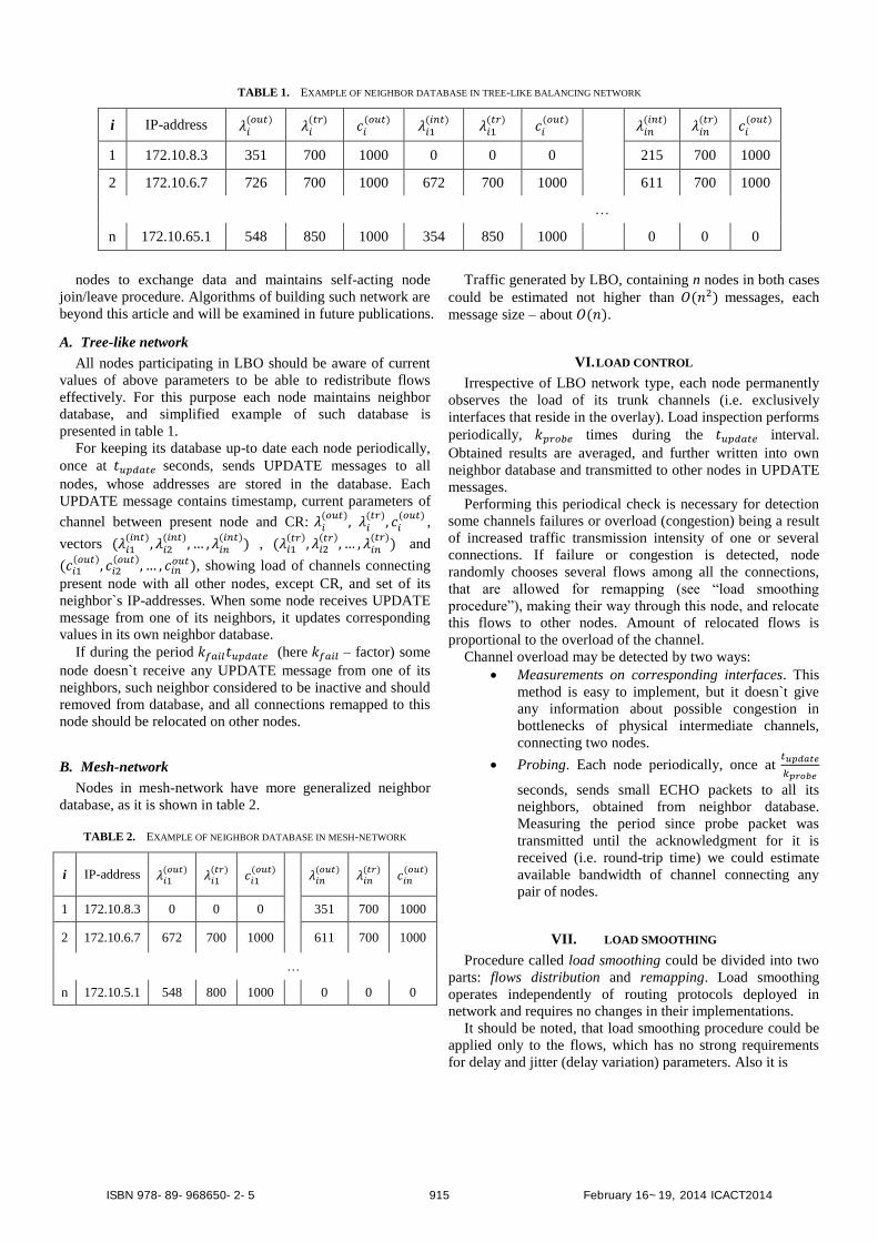
TABLE 1. EXAMPLE OF NEIGHBOR DATABASE IN TREE-LIKE BALANCING NETWORK
i IP-address
1 172.10.8.3 351 700 1000 0 0 0 215 700 1000
2 172.10.6.7 726 700 1000 672 700 1000 611 700 1000
…
n 172.10.65.1 548 850 1000 354 850 1000 0 0 0
nodes to exchange data and maintains self-acting node
join/leave procedure. Algorithms of building such network are
beyond this article and will be examined in future publications.
A. Tree-like network
All nodes participating in LBO should be aware of current
values of above parameters to be able to redistribute flows
effectively. For this purpose each node maintains neighbor
database, and simplified example of such database is
presented in table 1.
For keeping its database up-to date each node periodically,
once at seconds, sends UPDATE messages to all
nodes, whose addresses are stored in the database. Each
UPDATE message contains timestamp, current parameters of
channel between present node and CR:
,
vectors
,
and
, showing load of channels connecting
present node with all other nodes, except CR, and set of its
neighbor`s IP-addresses. When some node receives UPDATE
message from one of its neighbors, it updates corresponding
values in its own neighbor database.
If during the period (here – factor) some
node doesn`t receive any UPDATE message from one of its
neighbors, such neighbor considered to be inactive and should
removed from database, and all connections remapped to this
node should be relocated on other nodes.
B. Mesh-network
Nodes in mesh-network have more generalized neighbor
database, as it is shown in table 2.
TABLE 2. EXAMPLE OF NEIGHBOR DATABASE IN MESH-NETWORK
i IP-address
1 172.10.8.3 0 0 0 351 700 1000
2 172.10.6.7 672 700 1000 611 700 1000
…
n 172.10.5.1 548 800 1000 0 0 0
Traffic generated by LBO, containing n nodes in both cases
could be estimated not higher than messages, each
message size – about .
VI. LOAD CONTROL
Irrespective of LBO network type, each node permanently
observes the load of its trunk channels (i.e. exclusively
interfaces that reside in the overlay). Load inspection performs
periodically, times during the interval.
Obtained results are averaged, and further written into own
neighbor database and transmitted to other nodes in UPDATE
messages.
Performing this periodical check is necessary for detection
some channels failures or overload (congestion) being a result
of increased traffic transmission intensity of one or several
connections. If failure or congestion is detected, node
randomly chooses several flows among all the connections,
that are allowed for remapping (see ―load smoothing
procedure‖), making their way through this node, and relocate
this flows to other nodes. Amount of relocated flows is
proportional to the overload of the channel.
Channel overload may be detected by two ways:
Measurements on corresponding interfaces. This
method is easy to implement, but it doesn`t give
any information about possible congestion in
bottlenecks of physical intermediate channels,
connecting two nodes.
Probing. Each node periodically, once at
seconds, sends small ECHO packets to all its
neighbors, obtained from neighbor database.
Measuring the period since probe packet was
transmitted until the acknowledgment for it is
received (i.e. round-trip time) we could estimate
available bandwidth of channel connecting any
pair of nodes.
VII. LOAD SMOOTHING
Procedure called load smoothing could be divided into two
parts: flows distribution and remapping. Load smoothing
operates independently of routing protocols deployed in
network and requires no changes in their implementations.
It should be noted, that load smoothing procedure could be
applied only to the flows, which has no strong requirements
for delay and jitter (delay variation) parameters. Also it is
ISBN 978-89-968650-2-5 915 February 16~19, 2014 ICACT2014
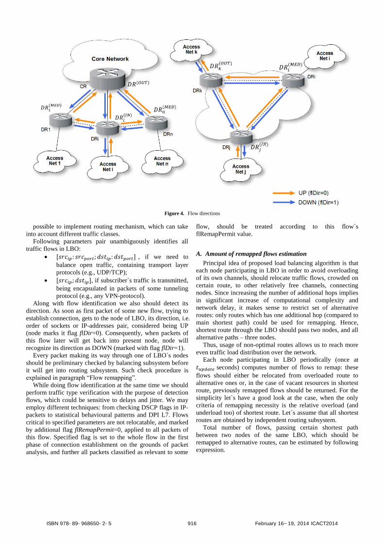
Figure 4. Flow directions
possible to implement routing mechanism, which can take
into account different traffic classes.
Following parameters pair unambiguously identifies all
traffic flows in LBO:
, if we need to
balance open traffic, containing transport layer
protocols (e.g., UDP/TCP);
, if subscriber`s traffic is transmitted,
being encapsulated in packets of some tunneling
protocol (e.g., any VPN-protocol).
Along with flow identification we also should detect its
direction. As soon as first packet of some new flow, trying to
establish connection, gets to the node of LBO, its direction, i.e.
order of sockets or IP-addresses pair, considered being UP
(node marks it flag flDir=0). Consequently, when packets of
this flow later will get back into present node, node will
recognize its direction as DOWN (marked with flag flDir=1).
Every packet making its way through one of LBO`s nodes
should be preliminary checked by balancing subsystem before
it will get into routing subsystem. Such check procedure is
explained in paragraph ―Flow remapping‖.
While doing flow identification at the same time we should
perform traffic type verification with the purpose of detection
flows, which could be sensitive to delays and jitter. We may
employ different techniques: from checking DSCP flags in IP-
packets to statistical behavioural patterns and DPI L7. Flows
critical to specified parameters are not relocatable, and marked
by additional flag flRemapPermit=0, applied to all packets of
this flow. Specified flag is set to the whole flow in the first
phase of connection establishment on the grounds of packet
analysis, and further all packets classified as relevant to some
flow, should be treated according to this flow`s
flRemapPermit value.
A. Amount of remapped flows estimation
Principal idea of proposed load balancing algorithm is that
each node participating in LBO in order to avoid overloading
of its own channels, should relocate traffic flows, crowded on
certain route, to other relatively free channels, connecting
nodes. Since increasing the number of additional hops implies
in significant increase of computational complexity and
network delay, it makes sense to restrict set of alternative
routes: only routes which has one additional hop (compared to
main shortest path) could be used for remapping. Hence,
shortest route through the LBO should pass two nodes, and all
alternative paths – three nodes.
Thus, usage of non-optimal routes allows us to reach more
even traffic load distribution over the network.
Each node participating in LBO periodically (once at
seconds) computes number of flows to remap: these
flows should either be relocated from overloaded route to
alternative ones or, in the case of vacant resources in shortest
route, previously remapped flows should be returned. For the
simplicity let`s have a good look at the case, when the only
criteria of remapping necessity is the relative overload (and
underload too) of shortest route. Let`s assume that all shortest
routes are obtained by independent routing subsystem.
Total number of flows, passing certain shortest path
between two nodes of the same LBO, which should be
remapped to alternative routes, can be estimated by following
expression.
ISBN 978-89-968650-2-5 916 February 16~19, 2014 ICACT2014

| |
Here – current load of shortest path, N – total number
of flows, which are not remapped yet, – estimation
function for residual resources of certain shortest path. In this
article for simplicity we`ll consider only linear form of
dependence on residual resources.
In the specified case load balancing system behaviour will
be symmetrical around the threshold load value (see fig. 5).
Negative number of flows informs us of possibility to return m
or less previously remapped flows to the shortest path.
Figure 5. Amount of flows to remap vs. current load of the shortest path
One of the well-known problems of load balancing systems
is oscillation of routes, especially when shortest path load is
around the threshold value. In order to remove this obstacle
we propose here additional function, which defines remapping
probability of some channel depending on closeness of load
value to threshold. Example of such oscillation avoidance (OA)
probability function may look like following one (see fig. 6).
( )
{
(
)
(
)
Figure 6. Probability of flow remapping
Here parameter a specifies area around the threshold value,
where probability will be less than 1, and – non-linearity
factor, defining probability decrease rate as it approaches the
threshold.
Now, having oscillation avoidance function, aimed to
reduce route oscillations, total number of flows, which should
be remapped to alternative routes, can be expressed as:
| |
Figure 7. Influence of proposed oscillation avoidance function on amount of
remapped flows
The influence of proposed additional OA probability
function on total amount of flows to be remapped is depicted
on figure 7. As can be seen from the graph, number of
remapped flows remains small enough in some area around
the threshold.
Adjusting a and variables we could achieve desired
system behavior. This issue lies beyond the article and may be
researched in future.
B. Flows distribution
Obtained, as it was described in the previous paragraph,
number of flows to remap should then be distributed among
other nodes, which have unused reserves of residual channel
bandwidth. In the elementary case such distribution may be
directly proportional to the residual bandwidth of each
roundabout alternative route.
1) Tree-like network model: Introducing linear estimation
function depending on residual unused bandwidth of
shortest route, passing through i-th node.
{
{
}
}
|
{
}
For the specified network topology amount of flows
between nodes j and CR to remap on the route passing
through i-th node could be expressed as:
∑
ISBN 978-89-968650-2-5 917 February 16~19, 2014 ICACT2014

TABLE 3. EXAMPLE OF FLOW-CHART DATABASE
Flow
ID
(srcIP:srcport;
dstIP:dstport) flRemapPermit isRemapped
1 (198.16.11.4:332;
8.42.7.16:7478) 1 1 172.10.5.8 172.10.16.25 172.12.4.9
2 (198.16.11.4:8080;
71.4.12.1:80) 0 - - - -
3 (198.16.131.4:9948;
144.1.12.8:2343) 1 0 - - -
…
In the case of negative , obtained number of
previously remapped flows could be returned from
each i-th roundabout route to the j-th node`s shortest
path.
Figure 8. Flows redistribution in tree-like network
2) Mesh-network: Expressions for the mesh-network case
are similar to ones examined above, but slightly more
generalized. Residual bandwidth estimation function:
{
{
}
{
}
}
| {
}
{
}
Number of flows to remap, utilizing OA function:
∑
Figure 9. Flows redistribution in mesh-network
C. Remapping
As amount of flows to be remapped for each of available
neighbours is obtained, node should relocate these flows from
overloaded shortest route to corresponding roundabout paths.
Each node in the LBO maintains its own flow-chart –
database, in which information about all the flows passing
through this node is stored. Simplified example of flow-chart
presented in table 3.
Node initiating remapping of one or several flows (node-
initiator, further denoted as
) sends REMAP message to
chosen node-mediator (
). This message contains set
of data strings, looking similar to following one:
{
}
Each data string contains information about single flow to
be remapped and IP-addresses of nodes in the roundabout-
route chain: node-initiator (
), node-mediator (
)
and node-recipient (
). All this information node-
initiator also stores in its own flow-chart (see table 3)
with flag isRemapped=1. Necessity to restrict number of
additional hops in alternative routes implies marking and
detachment of those flows, which already have been
ISBN 978-89-968650-2-5 918 February 16~19, 2014 ICACT2014

previously remapped from another node, to prevent recurring
procedure. For the purpose of such detachment is used special
flag isRemapped. Additional flag flRemapPermit shows if
certain flow could be remapped or not according to its QoS
demands. For example, traffic of such RT-applications as IP-
telephony, conferencing etc. should not be remapped to avoid
undesired and/or unacceptable delays.
Any node in LBO received REMAP message, containing
one of its interfaces IP-address in the field, becomes
mediator for this one or several flows, adds information
obtained from the message to its own flow-chart and sends
acknowledgement to initiator, notifying the latter about
successful procedure. After adding information about new
remapped flows into its flow-chart, mediator forms and sends
REMAP messages to corresponding recipients. Each node-
recipient , in it`s turn, adds information obtained from
message in its flow-chart and sends acknowledgement to
mediator.
In the case of tree-like network, there will be sole node-
recipient – core layer router (CR), which also resides in the
overlay.
Each packet received by LBO`s node initially gets into
proposed balancing subsystem, where it passes inspection:
whether packets of this flow already been observed on current
node or it`s a brand new connection. If flow-chart contains no
information about captured flow, this flow should be analyzed,
as it was explained above, and corresponding entry should be
added to flow-chart. Otherwise, if flow-chart has relevant
entry, and the flow wasn`t remapped (i.e. it passes LBO with
shortest route), captured packet gets into independent routing
subsystem. If flow-chart contains relevant entry and flow was
remapped, there are following possible balancing subsystem
actions to be applied to the packet (actually, to all packets of
certain flow):
Packet received by
, flDir=0. Packet avoids
routing subsystem and is forwarded immediately
to
, which IP-address could be obtained
from flow-chart.
Packet received by
, flDir=1. Packet gets
into routing subsystem and processed as usual.
Packet received by
, flDir=0. Packet
avoids routing subsystem and is forwarded
immediately to
, which IP-address could
be obtained from flow-chart.
Packet received by
, flDir=1. Packet
avoids routing subsystem and is forwarded
immediately to
, which IP-address could be
obtained from flow-chart.
Packet received by
, flDir=0. Packet gets
into routing subsystem and processed as usual.
Packet received by
, flDir=1. Packet
avoids routing subsystem and is forwarded
immediately to
, which IP-address could
be obtained from flow-chart.
At the same time it doesn`t matter, if the load balancing
procedure is applied to already established connection, or a
new one: after changing corresponding information in flow-
charts of all nodes participating in remapping or returning
previously remapped flow, certain flow will automatically
change the way it goes through LBO.
VIII. CONCLUSIONS
Proposed load balancing algorithm allows redistributing
traffic flows to improve QoS in the ISP network. Initially,
algorithm estimates unused channel resources by observing
current traffic loads, and then computes possible amount of
traffic flows to be remapped from overloaded routes. Proposed
algorithm has two modifications to choose, depending on
employed network topology, and implements only remapping
mechanism. Classification of flows by types and remapping
possibility without any detriment to QoS performance
considered being a distinct research problem, lying beyond the
area of present article and will be analyzed in future
publications.
REFERENCES
[1] Sheluhin O. I., Smolskiy S. M., Osin A. V. Self-Similar Processes in
Telecommunications. – John Wiley & Sons, Ltd, 2007. [2] Semenov Y., Pyattaev V., Chung C. The Distributed Service Network
architecture approach for Russian networks planning. Advanced
Communication Technology (ICACT), 2012 14th International Conference on. – IEEE, 2012.
[3] D.Mitra and K. G. Ramakrishna. A Case Study of Multiservice
Multipriority Traffic Engineering Design. In GLOBECOM, 1999. [4] B. Fortz and M. Thorup. Optimizing OSPF Weights in a Changing
World. In IEEE JSAC, 2002.
[5] B. Fortz and M. Thorup. Robust Optimization of OSPF/IS-IS Weights. In INOC, 2003.
[6] M. Zhang, B. Liu and B. Zhang. Multi-commodity flow traffic
engineering with hybrid MPLS/OSPF routing. In Proceedings of the 28th IEEE conference on Global telecommunications
(GLOBECOM'09), NJ, USA, 2009.
[7] J. Burns, T. Ott, A. Krzesinski, and K. Müller. Path selection and bandwidth allocation in MPLS networks. Perform. Eval., no. April
2002, pp. 1–25, 2003.
[8] A. Elwalid, C. Jin, S. Low, and I. Widjaja, ―MATE: MPLS adaptive traffic engineering,‖ INFOCOM, 2001.
[9] S. Kandula, D. Katabi, B. Davie, and A. Charny. Walking the tightrope:
Responsive yet stable traffic engineering. ACM SIGCOMM, 2005. [10] S. Sundaresan, C. Lumezanu. Autonomous traffic engineering with
self-configuring topologies. ACM SIGCOMM, 2010.
[11] D. Tuncer, M. Charalambides. Towards decentralized and adaptive network resource management. Serv. Management., 2011.
Anton Dort-Golts. Received the Specialist degree
in networks and telecommunication systems from State University of Telecommunication (SUT), St.
Petersburg, Russia, in 2009. At present time he`s a
PhD student at Networks Department, SUT, Saint-Petersburg, Russia. Currently works as an
Assistant at Networks Department, SUT, Saint-
Petersburg, Russia. Research interests include P2P networks, overlays, statistical traffic
characteristics.
ISBN 978-89-968650-2-5 919 February 16~19, 2014 ICACT2014

Olga Simonina received the PhD degree in
networks and telecommunication systems from State University of Telecommunication, St.
Petersburg, Russia, in 2005. In 2000-2003
worked at Department of Information Transmission, State University of
Telecommunication as an Assistant Professor,
since 2003 she has been working at Networks
Department, State University of Telecommunication, as an Assistant
Professor. In 2006 became an Associate Professor. Her current research interests cover quality of service, multiservice networks and overlay networks.
She is an ITU-T expert (ID 04908).
ISBN 978-89-968650-2-5 920 February 16~19, 2014 ICACT2014