load cell notes
TRANSCRIPT
7/28/2019 LOAD Cell Notes
http://slidepdf.com/reader/full/load-cell-notes 1/15
LOAD / FORCE CELLS
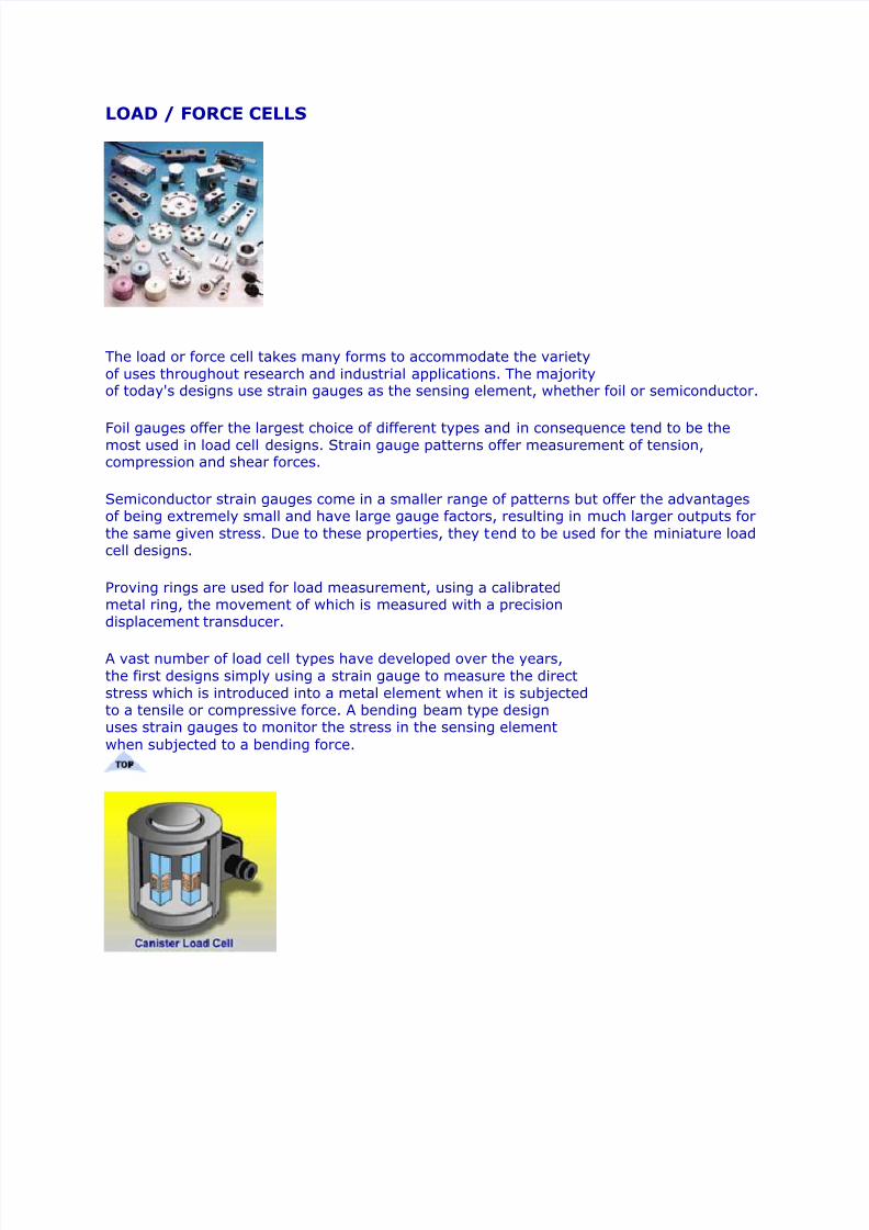
The load or force cell takes many forms to accommodate the variety
of uses throughout research and industrial applications. The majorityof today's designs use strain gauges as the sensing element, whether foil or semiconductor. Foil gauges offer the largest choice of different types and in consequence tend to be themost used in load cell designs. Strain gauge patterns offer measurement of tension,compression and shear forces. Semiconductor strain gauges come in a smaller range of patterns but offer the advantagesof being extremely small and have large gauge factors, resulting in much larger outputs for
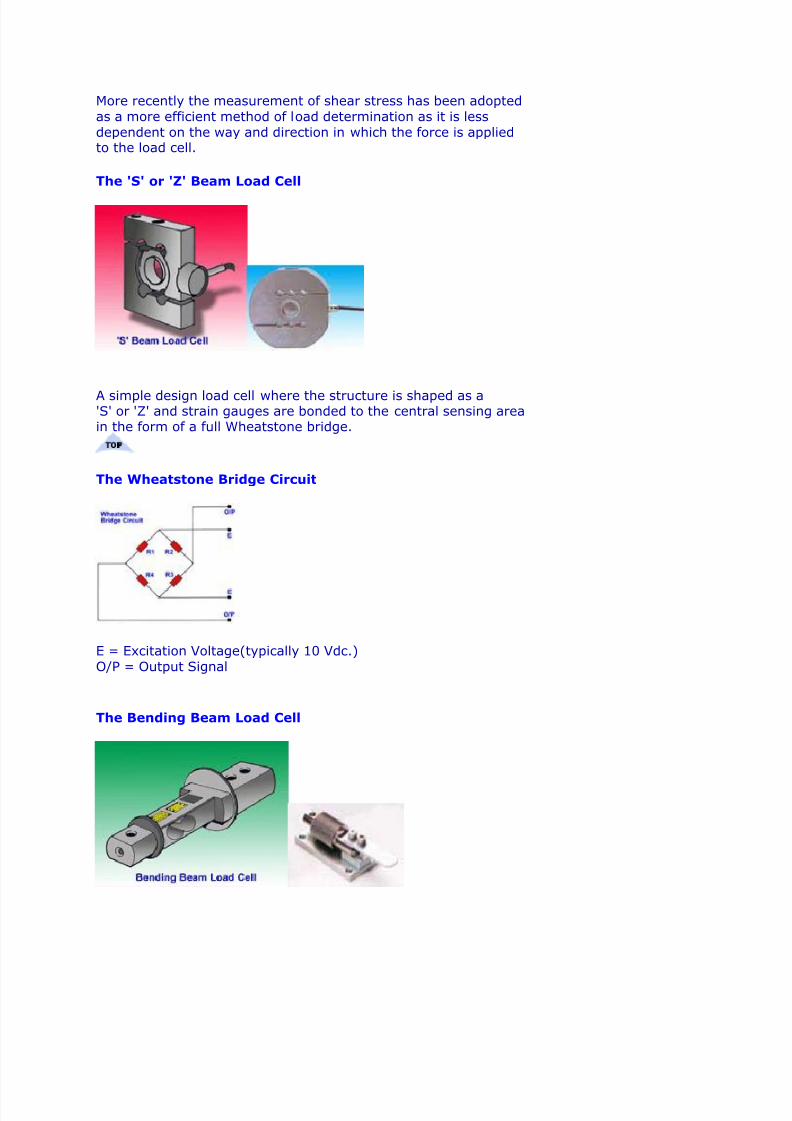
the same given stress. Due to these properties, they tend to be used for the miniature loadcell designs. Proving rings are used for load measurement, using a calibratedmetal ring, the movement of which is measured with a precisiondisplacement transducer. A vast number of load cell types have developed over the years,
the first designs simply using a strain gauge to measure the direct
stress which is introduced into a metal element when it is subjectedto a tensile or compressive force. A bending beam type designuses strain gauges to monitor the stress in the sensing element
when subjected to a bending force.
7/28/2019 LOAD Cell Notes
http://slidepdf.com/reader/full/load-cell-notes 2/15
More recently the measurement of shear stress has been adopted
as a more efficient method of load determination as it is less
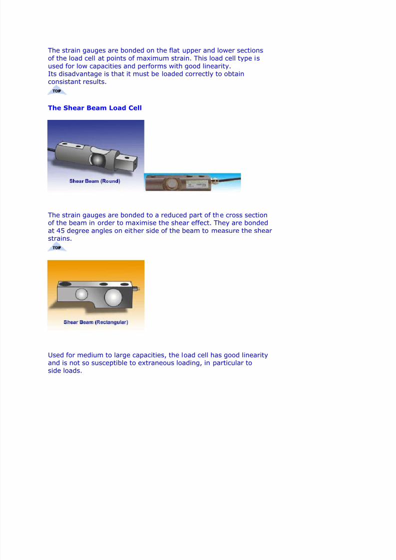
dependent on the way and direction in which the force is appliedto the load cell. The 'S' or 'Z' Beam Load Cell
A simple design load cell where the structure is shaped as a'S' or 'Z' and strain gauges are bonded to the central sensing areain the form of a full Wheatstone bridge.
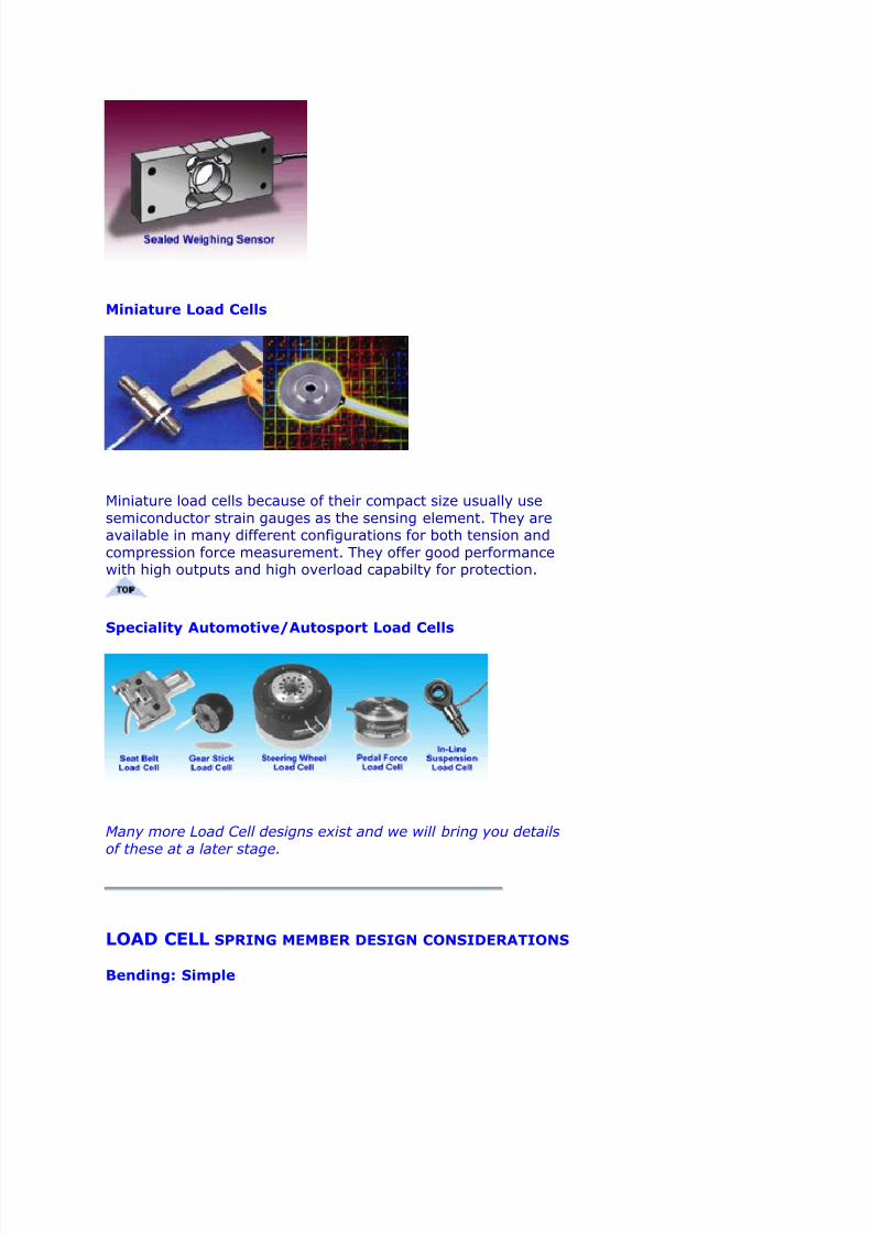
The Wheatstone Bridge Circuit
E = Excitation Voltage(typically 10 Vdc.)
O/P = Output Signal
The Bending Beam Load Cell
7/28/2019 LOAD Cell Notes
http://slidepdf.com/reader/full/load-cell-notes 3/15
The strain gauges are bonded on the flat upper and lower sections
of the load cell at points of maximum strain. This load cell type is
used for low capacities and performs with good linearity.Its disadvantage is that it must be loaded correctly to obtain
consistant results.
The Shear Beam Load Cell
The strain gauges are bonded to a reduced part of the cross sectionof the beam in order to maximise the shear effect. They are bonded
at 45 degree angles on either side of the beam to measure the shearstrains.
Used for medium to large capacities, the load cell has good linearityand is not so susceptible to extraneous loading, in particular toside loads.
7/28/2019 LOAD Cell Notes
http://slidepdf.com/reader/full/load-cell-notes 4/15
Miniature Load Cells
Miniature load cells because of their compact size usually use
semiconductor strain gauges as the sensing element. They areavailable in many different configurations for both tension and
compression force measurement. They offer good performancewith high outputs and high overload capabilty for protection.
Speciality Automotive/Autosport Load Cells
Many more Load Cell designs exist and we will bring you details
of these at a later stage.
LOAD CELL SPRING MEMBER DESIGN CONSIDERATIONS
Bending: Simple
7/28/2019 LOAD Cell Notes
http://slidepdf.com/reader/full/load-cell-notes 5/15
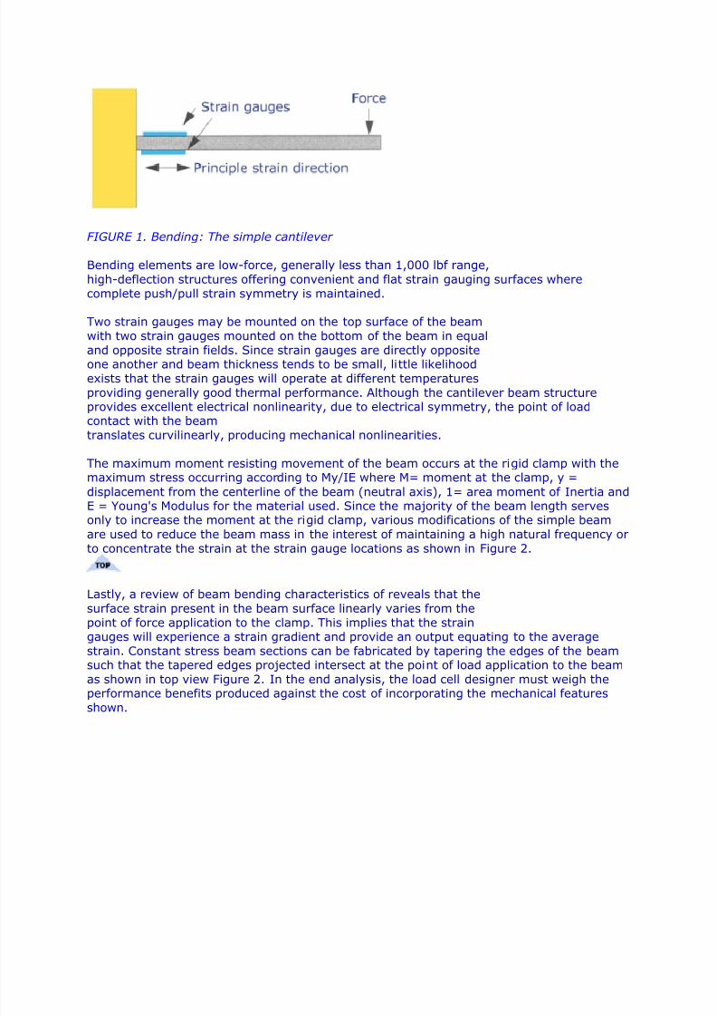
FIGURE 1. Bending: The simple cantilever
Bending elements are low-force, generally less than 1,000 lbf range,
high-deflection structures offering convenient and flat strain gauging surfaces where
complete push/pull strain symmetry is maintained.
Two strain gauges may be mounted on the top surface of the beam
with two strain gauges mounted on the bottom of the beam in equal
and opposite strain fields. Since strain gauges are directly oppositeone another and beam thickness tends to be small, little likelihood
exists that the strain gauges will operate at different temperatures
providing generally good thermal performance. Although the cantilever beam structureprovides excellent electrical nonlinearity, due to electrical symmetry, the point of loadcontact with the beam
translates curvilinearly, producing mechanical nonlinearities.
The maximum moment resisting movement of the beam occurs at the rigid clamp with themaximum stress occurring according to My/IE where M= moment at the clamp, y =
displacement from the centerline of the beam (neutral axis), 1= area moment of Inertia andE = Young's Modulus for the material used. Since the majority of the beam length servesonly to increase the moment at the rigid clamp, various modifications of the simple beam
are used to reduce the beam mass in the interest of maintaining a high natural frequency orto concentrate the strain at the strain gauge locations as shown in Figure 2.
Lastly, a review of beam bending characteristics of reveals that the
surface strain present in the beam surface linearly varies from the
point of force application to the clamp. This implies that the straingauges will experience a strain gradient and provide an output equating to the average
strain. Constant stress beam sections can be fabricated by tapering the edges of the beamsuch that the tapered edges projected intersect at the point of load application to the beam
as shown in top view Figure 2. In the end analysis, the load cell designer must weigh theperformance benefits produced against the cost of incorporating the mechanical features
shown.
7/28/2019 LOAD Cell Notes
http://slidepdf.com/reader/full/load-cell-notes 6/15
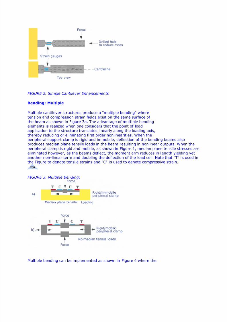
FIGURE 2. Simple Cantilever Enhancements Bending: Multiple Multiple cantilever structures produce a "multiple bending" wheretension and compression strain fields exist on the same surface of
the beam as shown in Figure 3a. The advantage of multiple bendingelements is realized when one considers that the point of load
application to the structure translates linearly along the loading axis,
thereby reducing or eliminating first order nonlinearities. When theperipheral support clamp is rigid and immobile, deflection of the bending beams alsoproduces median plane tensile loads in the beam resulting in nonlinear outputs. When the
peripheral clamp is rigid and mobile, as shown in Figure 1, median plane tensile stresses are
eliminated however, as the beams deflect, the moment arm reduces in length yielding yetanother non-linear term and doubling the deflection of the load cell. Note that "T" is used inthe Figure to denote tensile strains and "C" is used to denote compressive strain.
FIGURE 3. Multiple Bending:
Multiple bending can be implemented as shown in Figure 4 where the
7/28/2019 LOAD Cell Notes
http://slidepdf.com/reader/full/load-cell-notes 7/15
sensitivity of the load cell to off-axis loads is minimized. Coupled
dual-beam load cell configurations conveniently produce equal and
opposite axial loads within each of the beams in response to extraneous couples. Since thestrain gauges can be wired to cancel the effects of axial loads, the result is a load cell
structure largely insensitive to the point of load application and particularly well-suited tocommercial weighing applications. As the beams deflect, however, small changes in the
moment arm lengths result producing geometric nonlinearities. Additionally, axial forces produce nonlinearities in each beam whichtend to be equal and opposing, thus canceling each other. Althoughstrain gauging inside a drilled hole is more labor intensive, the design
lends itself to effective sealing. Often vacuum degassed silicone gel
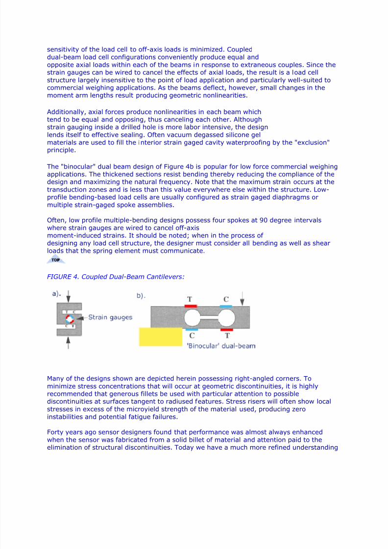
materials are used to fill the interior strain gaged cavity waterproofing by the "exclusion"principle. The "binocular" dual beam design of Figure 4b is popular for low force commercial weighing
applications. The thickened sections resist bending thereby reducing the compliance of thedesign and maximizing the natural frequency. Note that the maximum strain occurs at the
transduction zones and is less than this value everywhere else within the structure. Low-profile bending-based load cells are usually configured as strain gaged diaphragms or
multiple strain-gaged spoke assemblies.
Often, low profile multiple-bending designs possess four spokes at 90 degree intervals
where strain gauges are wired to cancel off-axismoment-induced strains. It should be noted; when in the process of
designing any load cell structure, the designer must consider all bending as well as shearloads that the spring element must communicate.
FIGURE 4. Coupled Dual-Beam Cantilevers:
Many of the designs shown are depicted herein possessing right-angled corners. To
minimize stress concentrations that will occur at geometric discontinuities, it is highlyrecommended that generous fillets be used with particular attention to possiblediscontinuities at surfaces tangent to radiused features. Stress risers will often show local
stresses in excess of the microyield strength of the material used, producing zero
instabilities and potential fatigue failures.
Forty years ago sensor designers found that performance was almost always enhanced
when the sensor was fabricated from a solid billet of material and attention paid to theelimination of structural discontinuities. Today we have a much more refined understanding
7/28/2019 LOAD Cell Notes
http://slidepdf.com/reader/full/load-cell-notes 8/15
of materials and material behavior along with the terminology to express these various
attributes and characteristics.
Bending: Ring
The bending ring shown in Figure 5 has a rich history and is popularly known as theMorehouse proving ring. The original design having been appropriated from Russia. TheMorehouse proving ring was and continues to be used as a transfer standard in both sensor
calibration systems and materials test systems. It is obvious from the design of the ring that
each leg of the ring must communicate axial loads while simultaneously experiencingbending. The fact that both axial and bending occur within the transduction zone of thesensor characterizes ring-style load cells.
The beauty of the proving ring with strain gauges installed as shown is the fact that allgauges of the wheatstone bridge ideally experience identical axial strain, resulting in
cancellation of axial strain effects in the output of the bridge. Another attribute of the ringstructure relates to the smoothly varying tensile and compressive moment-induced strains
that result due to loading of the cell. The original transduction method used with thestructural ring design predates strain gauges entirely where a manually "plucked" metal
reed and micrometer assembly were used todetect exceptionally small deflections of the ring. A hardened ball bearing acts as themicrometer-adjustable target surface against which the reed tip oscillates, where the reed is
also provided with a hardened cylindrical tip, the micrometer is adjusted to move the target
until the reed just contacts the target, dampening the reed response. The displacementsensitivity of this very mechanical system is impressive. The output of the sensor is viewed
directly on the micrometer scale.
It should be noted that the design of the bosses communicating load into the ring structure
significantly affects the performance of the ring. The optimum proportions and dimensionsof these bosses is as much determined by experience and test as it is by rigorous
mechanical design.
Bosses are often undercut or modified to be made more flexible in the interest of rejecting
off-axis loads trading off performance for off-axis load rejection. Likewise, transductionzones are provided with stress- concentrating notches to enhance output, natural frequencyand to reduce compliance. In some cases, the extent to which these boss and flexure
modifications extend are so radical as to almost defy characterization as a ring-based load
cell. The single common thread in all of these designs is the fact that transduction zonesmust communicate both bending and axial loads.
FIGURE 5. Bending: The ring:
7/28/2019 LOAD Cell Notes
http://slidepdf.com/reader/full/load-cell-notes 9/15
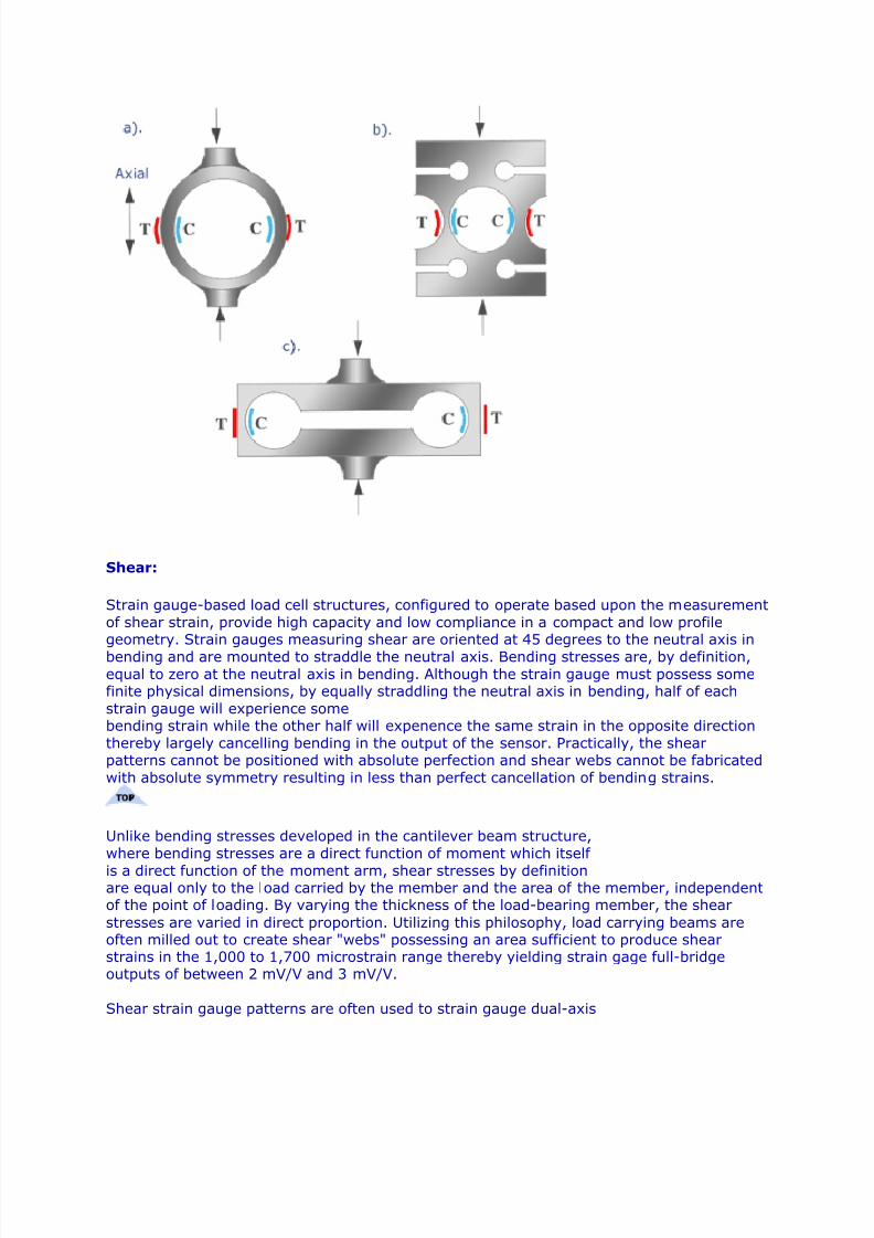
Shear: Strain gauge-based load cell structures, configured to operate based upon the measurement
of shear strain, provide high capacity and low compliance in a compact and low profilegeometry. Strain gauges measuring shear are oriented at 45 degrees to the neutral axis in
bending and are mounted to straddle the neutral axis. Bending stresses are, by definition,
equal to zero at the neutral axis in bending. Although the strain gauge must possess somefinite physical dimensions, by equally straddling the neutral axis in bending, half of each
strain gauge will experience somebending strain while the other half will expenence the same strain in the opposite direction
thereby largely cancelling bending in the output of the sensor. Practically, the shearpatterns cannot be positioned with absolute perfection and shear webs cannot be fabricated
with absolute symmetry resulting in less than perfect cancellation of bending strains.
Unlike bending stresses developed in the cantilever beam structure,
where bending stresses are a direct function of moment which itself
is a direct function of the moment arm, shear stresses by definitionare equal only to the load carried by the member and the area of the member, independentof the point of loading. By varying the thickness of the load-bearing member, the shear
stresses are varied in direct proportion. Utilizing this philosophy, load carrying beams areoften milled out to create shear "webs" possessing an area sufficient to produce shearstrains in the 1,000 to 1,700 microstrain range thereby yielding strain gage full-bridgeoutputs of between 2 mV/V and 3 mV/V.
Shear strain gauge patterns are often used to strain gauge dual-axis
7/28/2019 LOAD Cell Notes
http://slidepdf.com/reader/full/load-cell-notes 10/15
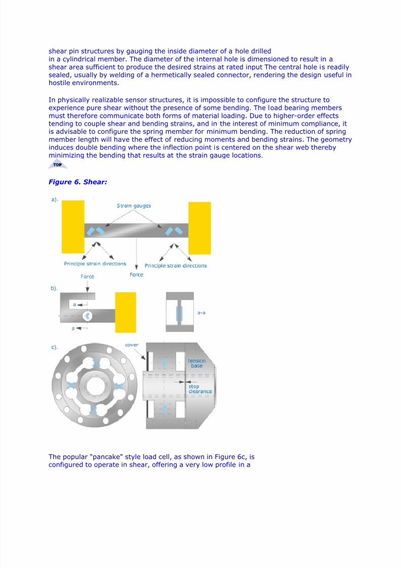
shear pin structures by gauging the inside diameter of a hole drilled
in a cylindrical member. The diameter of the internal hole is dimensioned to result in a
shear area sufficient to produce the desired strains at rated input The central hole is readilysealed, usually by welding of a hermetically sealed connector, rendering the design useful inhostile environments. In physically realizable sensor structures, it is impossible to configure the structure toexperience pure shear without the presence of some bending. The load bearing members
must therefore communicate both forms of material loading. Due to higher-order effectstending to couple shear and bending strains, and in the interest of minimum compliance, itis advisable to configure the spring member for minimum bending. The reduction of spring
member length will have the effect of reducing moments and bending strains. The geometry
induces double bending where the inflection point is centered on the shear web therebyminimizing the bending that results at the strain gauge locations.
Figure 6. Shear:
The popular "pancake" style load cell, as shown in Figure 6c, isconfigured to operate in shear, offering a very low profile in a
7/28/2019 LOAD Cell Notes
http://slidepdf.com/reader/full/load-cell-notes 11/15
design that is easily environmentally sealed and is largely insensitive
to off-axis loads. Generally, pancake style shear web load cells are
available in the 1,000 lbf and higher load ranges.
The pancake style load cell also easily accommodates dual electrically -separate strainbridges for high reliability applications. The high stiffness "tension"-base serves to allow the
measurement of tensile forces, acts to stiffen the load cell structure in compression and toallow the incorporation of overrange limiting stops for compression applications. Low profile
pancake load cells are not available in the under 500 lbf force range since the shear webthickness becomes exceedingly thin and difficult to manufacture. It should be noted that the
strain gage clamping fixtures for the pancake style sensor either pinch the shear webs to
avoid overstressing them during manufacturing or all cylindrical gaging holes shown arefilled with teflon plugs which provide clamping pressure due to volumetric expansion at
elevated
epoxy cure temperatures. The teflon plugs used are closely-toleranced to the diameter of the gauging holes and tend to extrude into the hole-to-hole slots reducing the clampingpressure as a function of he number of cure cycles they have been exposed to.
The design section of this article was written by Mr. James Pierson
7/28/2019 LOAD Cell Notes
http://slidepdf.com/reader/full/load-cell-notes 12/15
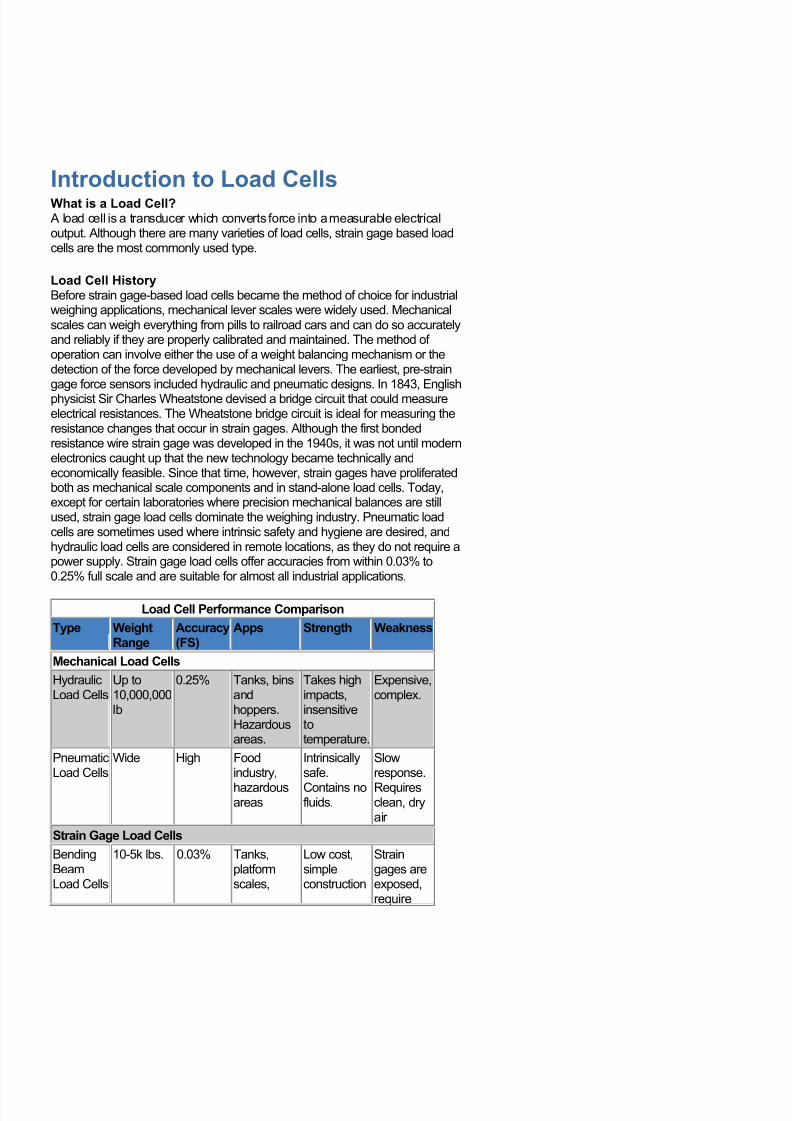
Introduction to Load Cells What is a Load Cell? A load cell is a transducer which converts force into a measurable electricaloutput. Although there are many varieties of load cells, strain gage based loadcells are the most commonly used type.
Load Cell HistoryBefore strain gage-based load cells became the method of choice for industrialweighing applications, mechanical lever scales were widely used. Mechanicalscales can weigh everything from pills to railroad cars and can do so accuratelyand reliably if they are properly calibrated and maintained. The method of operation can involve either the use of a weight balancing mechanism or thedetection of the force developed by mechanical levers. The earliest, pre-straingage force sensors included hydraulic and pneumatic designs. In 1843, Englishphysicist Sir Charles Wheatstone devised a bridge circuit that could measureelectrical resistances. The Wheatstone bridge circuit is ideal for measuring theresistance changes that occur in strain gages. Although the first bondedresistance wire strain gage was developed in the 1940s, it was not until modernelectronics caught up that the new technology became technically andeconomically feasible. Since that time, however, strain gages have proliferatedboth as mechanical scale components and in stand-alone load cells. Today,except for certain laboratories where precision mechanical balances are stillused, strain gage load cells dominate the weighing industry. Pneumatic loadcells are sometimes used where intrinsic safety and hygiene are desired, andhydraulic load cells are considered in remote locations, as they do not require apower supply. Strain gage load cells offer accuracies from within 0.03% to0.25% full scale and are suitable for almost all industrial applications.
Load Cell Performance Comparison
Type WeightRange
Accuracy(FS)
Apps Strength Weakness
Mechanical Load Cells
HydraulicLoad Cells
Up to10,000,000lb
0.25% Tanks, binsandhoppers.Hazardousareas.
Takes highimpacts,insensitivetotemperature.
Expensive,complex.
PneumaticLoad Cells
Wide High Foodindustry,
hazardousareas
Intrinsicallysafe.
Contains nofluids.
Slowresponse.
Requiresclean, dryair
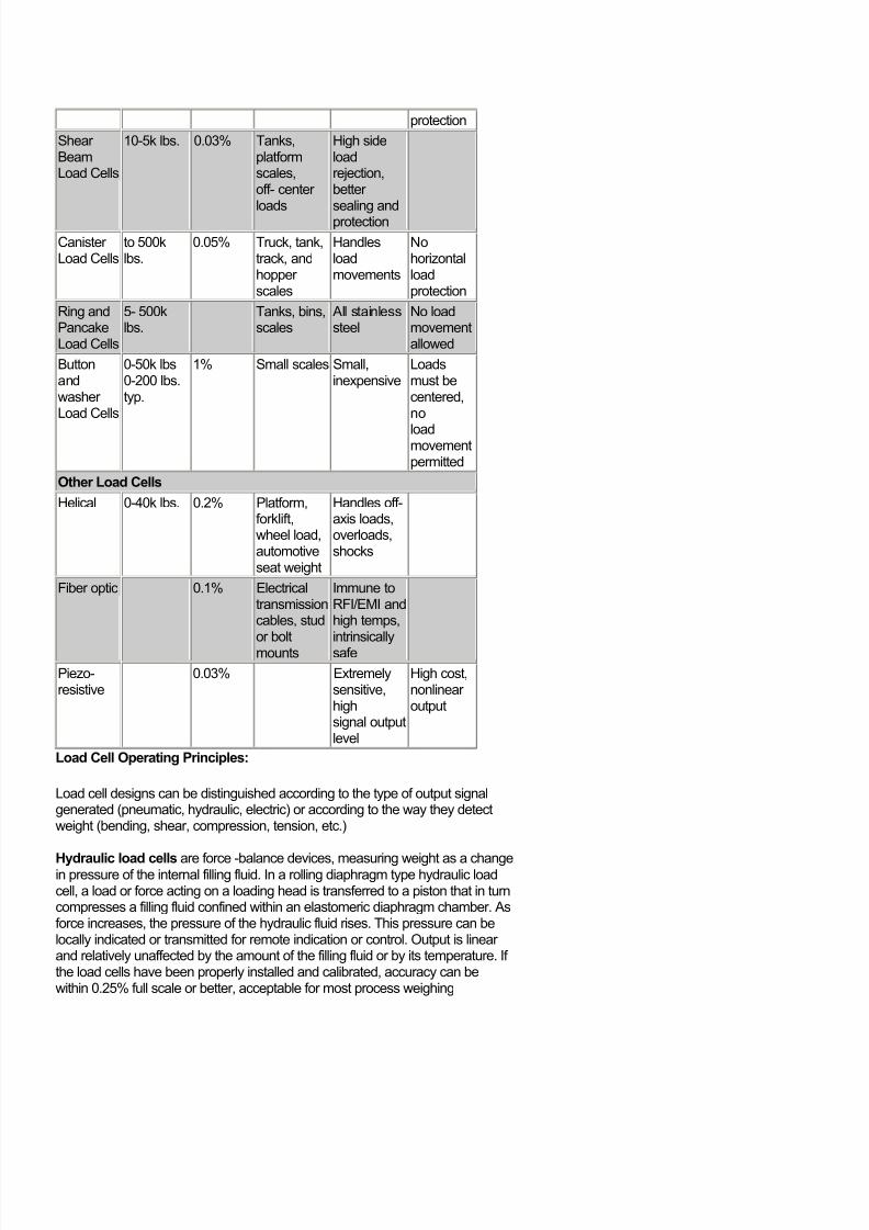
Strain Gage Load Cells
BendingBeamLoad Cells
10-5k lbs. 0.03% Tanks,platformscales,
Low cost,simpleconstruction
Straingages areexposed,require
7/28/2019 LOAD Cell Notes
http://slidepdf.com/reader/full/load-cell-notes 13/15
protection
Shear BeamLoad Cells
10-5k lbs. 0.03% Tanks,platformscales,off- center loads
High sideloadrejection,better sealing andprotection
Canister Load Cells
to 500klbs.
0.05% Truck, tank,track, andhopper scales
Handlesloadmovements
Nohorizontalloadprotection
Ring andPancakeLoad Cells
5- 500klbs.
Tanks, bins,scales
All stainlesssteel
No loadmovementallowed
Buttonandwasher Load Cells
0-50k lbs0-200 lbs.typ.
1% Small scales Small,inexpensive
Loadsmust becentered,no
loadmovementpermitted
Other Load Cells
Helical 0-40k lbs. 0.2% Platform,forklift,wheel load,automotiveseat weight
Handles off-axis loads,overloads,shocks
Fiber optic 0.1% Electricaltransmissioncables, studor boltmounts
Immune toRFI/EMI andhigh temps,intrinsicallysafe
Piezo-resistive
0.03% Extremelysensitive,highsignal outputlevel
High cost,nonlinear output
Load Cell Operating Principles:
Load cell designs can be distinguished according to the type of output signalgenerated (pneumatic, hydraulic, electric) or according to the way they detectweight (bending, shear, compression, tension, etc.)
Hydraulic load cells are force -balance devices, measuring weight as a changein pressure of the internal filling fluid. In a rolling diaphragm type hydraulic loadcell, a load or force acting on a loading head is transferred to a piston that in turncompresses a filling fluid confined within an elastomeric diaphragm chamber. Asforce increases, the pressure of the hydraulic fluid rises. This pressure can belocally indicated or transmitted for remote indication or control. Output is linear and relatively unaffected by the amount of the filling fluid or by its temperature. If the load cells have been properly installed and calibrated, accuracy can bewithin 0.25% full scale or better, acceptable for most process weighing
7/28/2019 LOAD Cell Notes
http://slidepdf.com/reader/full/load-cell-notes 14/15
applications. Because this sensor has no electric components, it is ideal for usein hazardous areas. Typical hydraulic load cell applications include tank, bin, andhopper weighing. For maximum accuracy, the weight of the tank should beobtained by locating one load cell at each point of support and summing their outputs.
Pneumatic load cells also operate on the force-balance principle. Thesedevices use multiple dampener chambers to provide higher accuracy than can ahydraulic device. In some designs, the first dampener chamber is used as a tareweight chamber. Pneumatic load cells are often used to measure relatively smallweights in industries where cleanliness and safety are of prime concern. Theadvantages of this type of load cell include their being inherently explosion proof and insensitive to temperature variations. Additionally, they contain no fluids thatmight contaminate the process if the diaphragm ruptures. Disadvantages includerelatively slow speed of response and the need for clean, dry, regulated air or nitrogen.
Strain-gage load cells convert the load acting on them into electrical signals.The gauges themselves are bonded onto a beam or structural member that
deforms when weight is applied. In most cases, four strain gages are used toobtain maximum sensitivity and temperature compensation. Two of the gaugesare usually in tension, and two in compression, and are wired with compensationadjustments as shown in Figure 7-2. When weight is applied, the strain changesthe electrical resistance of the gauges in proportion to the load. Other load cellsare fading into obscurity, as strain gage load cells continue to increase their accuracy and lower their unit costs.
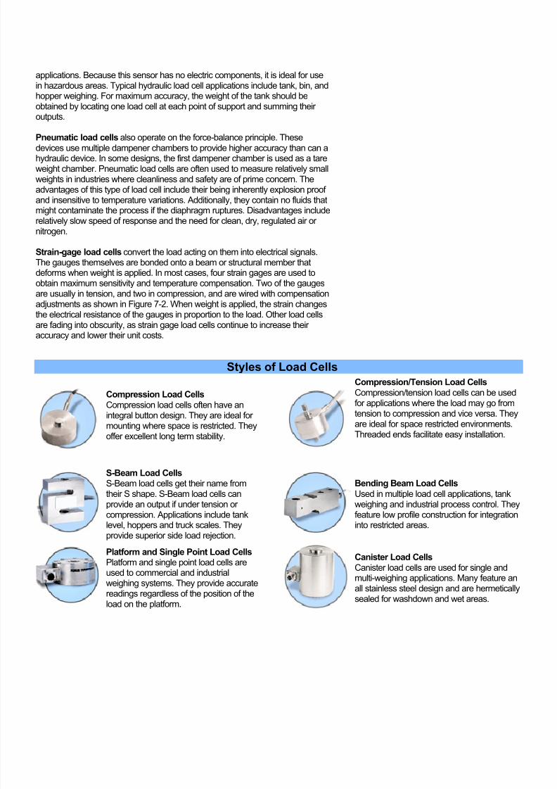
Styles of Load Cells Compression Load Cells Compression load cells often have an
integral button design. They are ideal for mounting where space is restricted. Theyoffer excellent long term stability.
Compression/Tension Load Cells Compression/tension load cells can be usedfor applications where the load may go from
tension to compression and vice versa. Theyare ideal for space restricted environments.Threaded ends facilitate easy installation.
S-Beam Load Cells S-Beam load cells get their name fromtheir S shape. S-Beam load cells canprovide an output if under tension or compression. Applications include tanklevel, hoppers and truck scales. Theyprovide superior side load rejection.
Bending Beam Load Cells Used in multiple load cell applications, tankweighing and industrial process control. Theyfeature low profile construction for integrationinto restricted areas.
Platform and Single Point Load Cells Platform and single point load cells areused to commercial and industrialweighing systems. They provide accuratereadings regardless of the position of theload on the platform.
Canister Load Cells Canister load cells are used for single andmulti-weighing applications. Many feature anall stainless steel design and are hermeticallysealed for washdown and wet areas.

7/28/2019 LOAD Cell Notes
http://slidepdf.com/reader/full/load-cell-notes 15/15
Low Profile Load Cells Compression and tension/compressionload cells. Mounting holes and femalethreads provide easy installation. Usedfrequently in weighing research and in-lineforce monitoring.