local buckling prediction for large wind turbine blades
TRANSCRIPT

Copyright © 2011 Tech Science Press CMC, vol.25, no.2, pp.177-193, 2011
Local Buckling Prediction for Large Wind Turbine Blades
W. Liu, X. Y. Su, Y. R. An, and K. F. Huang1
Abstract: Local buckling is a typical failure mode of large scale composite windturbine blades. A procedure for predicting the onset and location of local buck-ling of composite wind turbine blades under aerodynamic loads is proposed in thispaper. This procedure is distinct from its counterparts in adopting the pressure dis-tributions obtained from Computational Fluid Dynamics (CFD) calculations as theloads. The finite element method is employed to investigate local buckling resis-tance of the composite blade. To address the mismatch between the unstructuredCFD grids of the blade surface and the finite shell elements used during the buck-ling analysis, an interpolation code is developed, allowing mapping the pressurecomputed by using CFD to the finite element model. With the well documentedNational Renewable Energy Laboratory phase VI wind turbine blade, the proce-dure is demonstrated to be capable of yielding satisfactory results. Comparisonwith results obtained by using the blade surface pressure distributions calculatedusing a simple method is also conducted.
Keywords: Wind turbine blade, local buckling, CFD technique, finite elementmethod.
1 Introduction
Development of renewable energy sources has been rapid since the emergence ofenergy crisis in the 1970s, and since then the urge for clean energy to moderatethe greenhouse effect has been driving the research in this field. Among the maincandidate renewable energy sources, wind energy is the fastest-growing one par-tially because of its technological maturity and relative cost competitiveness. Inorder to harvest energy more efficiently from the wind and due to cost-effectiveconsiderations, the size of the wind turbine has increased over the decades.
The blade is one of the most important components in a wind turbine which nowa-days is designed according to refined aerodynamics in order to capture as much
1 Peking Univ, LTCS and Dept Mech & Aero Engn, Coll Engn, Beijing 100871, China. Correspond-ing author, Email address: [email protected] (K. F. Huang).

178 Copyright © 2011 Tech Science Press CMC, vol.25, no.2, pp.177-193, 2011
energy as possible from the wind. Modeling of the wind turbine blade has been re-ceiving more and more research attention (Lin, Lee and Lin, 2008). Currently mostwind turbine blades are fabricated with composite materials as composite materialscan satisfy complex design constraints such as lower weight and proper stiffness,while providing good resistance to the static and fatigue loading. The design ofcomposite wind turbine blades is a challenging problem due to the need for push-ing the material utilization to the limit in order to obtain light and cost effectivestructures. As a consequence of the minimum material design strategy, the bladesare becoming thin-walled, such that structural instability or local buckling wouldoccur. It has been recognized that while the design of the wind turbine bladeswas dictated by fatigue considerations in the past (Shokrieh and Rafiee, 2006),nowadays the driving design parameter within the wind turbine blade industry hasshifted from fatigue issues to structural instability as the blades become larger andnew materials are taken into use.
There are considerable works concerning buckling of the wind turbine blades (Bir,2001; Hermann, Mamarthupatti and Locke, 2005; Lund and Johansen, 2008; Cairnset al, 2000; Walter et al, 2001; McKittrick et al, 2001; Kong, Bang and Sugiyama,2005; Jensen et al, 2006). Bir (2001) developed a computerized method for pre-liminary structural design of composite wind turbine blades. The design code de-veloped therein used ultimate-strength and buckling-resistance criteria. Hermann,Mamarthupatti and Locke (2005) investigated the buckling and post-buckling be-havior of a wind turbine blade substructure using finite element method. The anal-ysis was correlated with data from a static test and modified lamination scheduleswere provided to improve the buckling behaviour of the blade structure. Lund andJohansen (2008) proposed a multi-material topology optimization approach to ob-tain buckling optimized multi-material designs of wind turbine blades. Walter etal (2001) experimentally determined the buckling strength of pultruded fibreglasswind turbine blade sections and the test data were compared to the results of threeanalytical buckling prediction methods.
However, the aforementioned works all employed some reduced forms of loads toinvestigate the buckling strength of the wind turbine blades, such as four-point-bending (Hermann, Mamarthupatti and Locke, 2005; Walter et al, 2001), bendingmoment distribution at some positions along the spanwise direction of the blades(Bir, 2001; Kong, Bang and Sugiyama, 2005; Jensen et al, 2006). These reducedforms of loads are reasonable to some extent when the global load-carrying capa-bility and buckling strength are to be determined. Nevertheless, as the onset andthe location of local buckling are concerned, these reduced forms of loads are in-sufficient and more detailed load conditions such as the pressure distribution onthe blade surface are requested. McKittrick et al (2001) performed buckling and

Local Buckling Prediction for Large Wind Turbine Blades 179
postbuckling analysis of a wind turbine blade using finite element method. Theblade surface pressure they adopted therein was obtained by adjusting the dynamicpressure calculated by using Bernoulli’s equation. Since the flow field around theblade is considerably complex, Bernoulli’s equation is not capable of reflecting therich physics such as stall and separation, and therefore the calculated blade sur-face pressure was not satisfactorily accurate. More accurate pressure distribution isneeded for the prediction of the onset and the location of local buckling.
There has been an increasing interest in using Computational Fluid Dynamics(CFD) techniques to predict the aerodynamic performance and the load charac-teristics of wind turbines (Sezer-Uzol and Long, 2006; Laursen, Enevoldsen andHjort, 2007; Carcangiu et al, 2007; Ferrer and Munduate, 2007; Baxevanou et al,2008; Park, Chang and Cho, 2007). Compared with some simplified methods suchas Blade Element Momentum theory, CFD methods can offer more detailed loads,such as local pressure distribution on the blade surface. It has been proved that al-though there are still some aspects to be explored for wind turbine application, theCFD technique is capable of consistently reproducing the experimental results suchas the measured aerodynamic forces along the blade span even under highly three-dimensional (3D) and extreme stall conditions (Hansen, 2006). Thus CFD can beused to calculate the blade surface pressure which can be used as the aerodynamicloads in the prediction of the onset and location of local buckling.
In this paper, a procedure for predicting the onset and location of local buckling ofcomposite wind turbine blades using the pressure distribution obtained from CFD isproposed. The full 3D steady RANS (Reynolds-averaged Navier–Stokes equations)approach is used to simulate the flow field around a rotating blade of a horizontalaxis wind turbine and the blade surface pressure is obtained. Then the finite elementmethod is applied to investigate the onset and location of the local buckling of thecomposite blade . In order to address the mismatch between the unstructured gridsused to discretize the surface of the blade during CFD calculations and the shellelements used during buckling analysis, a code has been developed for mappingthe pressure computed by using CFD to the finite element model. The procedureis demonstrated with the NREL phase VI wind turbine blade. Comparison withresults obtained by using the pressure distribution in (McKittrick et al, 2001) isalso performed.

180 Copyright © 2011 Tech Science Press CMC, vol.25, no.2, pp.177-193, 2011
2 Basic theory
2.1 CFD calculations
The CFD calculation is based on the steady, incompressible Reynolds-averagedNavier-Stokes (RANS) equations
∂ui
∂xi= 0 (1)
∂
∂x j(uiu j) =− 1
ρ
∂ p∂xi
+ν∂ 2ui
∂x2i
+∂
∂x j(−u′iu
′j) (2)
Where ui and xi are the mean velocity component and coordinate in direction irespectively; p is the pressure; ρ is the density; ν is the dynamic viscosity of thefluid.
The Boussinesq hypothesis relates the Reynolds stresses to the mean velocity gra-dients
−ρu′iu′j = µt
(∂ui
∂x j+
∂u j
∂xi
)− 2
3
(ρκ + µt
∂ui
∂xi
)δi j (3)
Where µ t is the turbulent viscosity, and κ is the turbulent kinetic energy.
The Spalart-Allmaras (S-A) (Spalart and Allmaras, 1994) turbulence model hasbeen chosen to close the equations. The Spalart-Allmaras model is a one-equationmodel which is designed specifically for aerospace applications. It has also shownfairly good capabilities for turbomachinery applications. Since the blade is per-forming a steadily rotating motion, the governing equations need to be solved inthe rotating frame of reference.
2.2 Linear-elastic buckling finite element analysis
The linear-elastic buckling finite element analysis of structures can be formulatedas an eigenvalue problem as following (Zienkiewicz, 1989):
(Ke +λKG)U = 0 (4)
Where Ke is the linear-elastic stiffness matrix, KG the geometric stiffness matrix,λ the buckling load factor, U the buckling mode, respectively.
3 CFD calculation results and validation
3.1 Numerical model
The CFD computations are performed using the commercial finite-volume solverFluent with a steady-RANS approach. The well documented two-bladed NREL

Local Buckling Prediction for Large Wind Turbine Blades 181
phase VI wind turbine is chosen to be simulated, mainly because there is plentyof experimental data about the aerodynamics of this turbine so that the simulationresults can be benchmarked. The blade is ∼5m long, tapered and twisted along thespanwise direction. The detailed data about the geometry, the blade chord and twistdistributions can be found in (Hand et al, 2001), and the configuration of the bladeis shown in Fig. 1.
Figure 1: NREL phase VI wind turbine blade
For this study, unstructured grids have been created using tetrahedral and prismaticelements. Only one blade is modeled and periodic boundary conditions are used. Inall cases fully turbulence flow is assumed. The S-A turbulence one equation modelin conjunction with wall function is selected for these computations. For boundaryconditions, in the upwind free stream velocities condition is given, and the range offree stream velocities is from 7m/s to 25m/s; in the downwind is the pressure outletcondition. Second order discretization schemes are used for all variables and thePRESTO algorithm is selected to solve the pressure-velocity coupling.
3.2 Numerical results and experimental validation
The outlined methodology has been applied to predict the pressure coefficient (Cp)distribution using the NREL NASA-AMES experiments (Hand et al, 2001) for val-idation. The simulated conditions corresponded to free stream velocities rangingfrom 7m/s to 25m/s and a rotational speed of 71.63rpm. Fig. 2 shows the Cpcomparison between CFD and experimental data for the 30%, 47%, 63% and 80%spanwise stations with a free stream velocity of 15m/s. It can be seen that the CFDcomputations are able to reproduce quite accurately the experimental Cp values atthese locations, except that there are some discrepancies at the 30% spanwise sta-

182 Copyright © 2011 Tech Science Press CMC, vol.25, no.2, pp.177-193, 2011
tion, which are thought to be due to the effect of the tower that is temporarily notconsidered in the simulations.
One can naturally figure out that the results such as the pressure distributions ob-tained by CFD can be used in the structural design of the wind turbine blade. How-ever when finite element shell model of the blade is employed in the structural de-sign, which is often the case especially as the blade is becoming larger and larger,the number of the shell elements is generally much less than that of the unstruc-tured grids that are used to discretize the surface of the blade and on which theblade surface pressures are obtained during the CFD calculations. This mismatchwill be addressed and the surface pressures obtained from CFD will be mapped tothe finite element model of the blade to perform buckling analysis in the followingsections.
Second order discretization schemes are used for all variables and the PRESTO algorithm is selected to solve the pressure-velocity coupling.
3.2 Numerical results and experimental validation
The outlined methodology has been applied to predict the pressure coefficient (Cp) distribution using the NREL NASA-AMES experiments (Hand et al, 2001) for validation. The simulated conditions corresponded to free stream velocities ranged from 7m/s to 25m/s and a rotational speed of 71.63rpm. Fig. 2 shows the Cp comparison between CFD and experimental data for the 30%, 47%, 63% and 80% spanwise stations with a free stream velocity of 15m/s. It can be seen that the CFD computations are able to reproduce quite accurately the experimental Cp values at these locations, except that there are some discrepancies at the 30% spanwise station, which are thought to be due to the effect of the tower that is temporarily not considered in the simulations. One can naturally figure out that the results such as the pressure distributions obtained by CFD can be used in the structural design of the wind turbine blade. However when finite element shell model of the blade is employed in the structural design, which is often the case especially as the blade is becoming larger and larger, the number of the shell elements is generally much less than that of the unstructured grids that are used to discretize the surface of the blade and on which the blade surface pressures are obtained during the CFD calculations. This mismatch will be addressed and the surface pressures obtained from CFD will be mapped to the finite element model of the blade to perform buckling analysis in the following sections.
Figure 2: Pressure coefficient distributions at (a) 30% spanwise station, (b) 47%
spanwise station, (c) 63% spanwise station, and (d) 80% spanwise station, with afree stream velocity of 15m/s.

Local Buckling Prediction for Large Wind Turbine Blades 183
4 Buckling analysis of the blade
The wind turbine blade is usually modeled as 3D beams owing to small scale andhigh aspect ratio in the past. However, as the scale of the blade becomes larger andlarger and composite materials are taken into use, the blade is actually a class ofthin-walled shell structure. In order to capture the mechanical behavior of the blademore accurately, detailed finite element models such as 3D shell models are beingfrequently used in the investigation and design of the wind turbine blade. In thispaper, 3D finite element shell model is employed to predict the onset and locationof local buckling of the wind turbine blade.
4.1 Blade geometry and components
In order to make use of the aerodynamic loads calculated using CFD in section3, again the NREL phase VI wind turbine blade is chosen to be modeled and toperform the buckling analysis.
The root of the blade starts at the hub connection, at a radius 0.508m from thecentre of the hub. The blade has a cylinder with 0.218m diameter extending from0.508m to 0.660m and then tapers to a diameter 0.183 from 0.660m to 0.883malong the spanwise direction. There is a transition from the circular section at the0.883m spanwise station to a 0.737m chord S809 airfoil at the 1.257m. Outboardfrom 1.257m to the tip, the blade, having the S809 airfoil, is linearly tapered andnonlinearly twisted along the spanwise direction. The detailed data pertinent to thegeometry of the investigated blade is listed in (Hand et al, 2001) and the geometricmodel of the blade built with the finite element package ANSYS is shown in Fig.3(a).
The investigated blade consists of two primary components: shell and web, dis-played in the cross-section shown in Fig. 3(b). The shell is responsible to helpcreate the required pressure distribution on the blade. The leading edge of the up-per and lower shell and the web of the blade compose a D-spar, which is also calledthe main beam and supports loads on the blade that arise from different sources.
4.2 Blade layup
Since detailed 3D finite element shell model is to be employed to investigate theonset and location of the local buckling, the layup of the composite blade is a pre-requisite for this investigation. Although we tried our best we did not find anyinformation about the original composite layup of the NREL phase VI wind tur-bine blade in open literature. However, fortunately the purpose of this paper is topropose and demonstrate a procedure for local buckling prediction for wind turbineblades, we need not focus on a specific layup. Hereby, referring to (McKittrick et

184 Copyright © 2011 Tech Science Press CMC, vol.25, no.2, pp.177-193, 2011
Figure 2: Pressure coefficient distributions at (a) 30% spanwise station, (b) 47% spanwise station, (c) 63% spanwise station, and (d) 80% spanwise station, with a free
stream velocity of 15m/s.
4 Buckling analysis of the blade
The wind turbine blade is usually modeled as 3D beams owing to small scale and high aspect ratio in the past. However, as the scale of the blade becomes larger and larger and composite materials are taken into use, the blade is actually a class of thin-walled shell structure. In order to capture the mechanical behavior of the blade more accurately, detailed finite element models such as 3D shell models are being frequently used in the investigation and design of the wind turbine blade. In this paper, 3D finite element shell model is employed to predict the onset and location of local buckling of the wind turbine blade.
4.1 Blade geometry and components
In order to make use of the aerodynamic loads calculated using CFD in section 3, again the NREL phase wind turbine bladeⅥ is chosen to be modeled and to perform the buckling analysis.
The root of the blade starts at the hub connection, at a radius 0.508m from the centre of the hub. The blade has a cylinder with 0.218m diameter extending from 0.508m to 0.660m and then tapers to a diameter 0.183 from 0.660m to 0.883m along the spanwise direction. There is a transition from the circular section at the 0.883m spanwise station to a 0.737m chord S809 airfoil at the 1.257m. Outboard from 1.257m to the tip, the blade, having the S809 airfoil, is linearly tapered and nonlinearly twisted along the spanwise direction. The detailed data pertinent to the geometry of the investigated blade is listed in (Hand et al, 2001) and the geometric model of the blade built with the finite element package ANSYS is shown in Fig. 3(a). The investigated blade consists of two primary components: shell and web, displayed in the cross-section shown in Fig. 3(b). The shell is responsible to help create the required pressure distribution on the blade. The leading edge of the upper and lower shell and the web of the blade compose a D-spar, which is also called the main beam and supports loads on the blade that arise from different sources.
Figure 3: (a) The geometrical model, and (b) the cross-section, of the NREL phaseVI wind turbine blade.
al, 2001), a generic composite layup is designed in this paper for the NREL phaseVI wind turbine blade and for the local buckling investigation purpose.
According to the designed composite layup of the blade, the cylindrical sections,the transition section and the D-spar (the main beam) are relatively stiffer than thetailing edge of the shell structure as the former supports most of the loads. Thedetailed layup schedule of the blade is presented in Tab. 1.
Each of the GRP layers in the layup is modeled as orthotropic in a given layer,with two of the principal material axes in the plane of the shell. The orientationof the material axes (fibre directions) varies from one layer to the next. Materialparameters listed in Tab. 2 are used to model various layers in the GRP layup.
Table 1: The layup schedule of the composite wind turbine blade
Component Layup scheduleCylindrical sections & D spar [±45/03/±45/03/+45]s
Tailing edge of the shell structure [±45/0/Balsa/0/±45]
The parameters listed in Tab. 2 are derived from experimental data (Mandell and

Local Buckling Prediction for Large Wind Turbine Blades 185
Table 2: Material mechanical properties
Material property A130(0˚) DB120(±45˚) Balsa woodEx (GPa) 31.7 26.2 0.187Ey (GPa) 7.58 6.55 0.061Ez (GPa) 7.58 6.55 4.07
υxy 0.32 0.39 0.67υyz 0.32 0.35 0.01υxz 0.32 0.32 0.02
Gxy (GPa) 3.45 4.14 0.020Gyz (GPa) 3.10 3.72 0.150Gxz (GPa) 3.10 3.72 0.220ρ (kg/m3) 1714 1714 153
thickness (mm) 0.571 0.203 9.53
Samborsky, 1997). The Al30 and DB120 lamina use E-glass fibres that are embed-ded in polymer matrix. The A130 lamina is considered for the 0 degree ply layups,while the DB120 lamina is used for the ±45 degree ply layups. The balsa wood isused as the filler in sandwich-type layups to increase the buckling resistance whileminimizing the weight.
4.3 Finite element model
The structure of the composite blade is modeled with layered shell elements (ele-ment type SHELL99) capable of representing layer characteristics throughout theshell thickness. Shell99, which is designed to model thin composite plates and shellstructures, has eight nodes with six degrees of freedom at each node: translations inthe nodal X, Y, and Z directions and rotations about the nodal X-, Y -, and Z-axes.
Meshing size is well chosen to obtain reliable results. The number of the elementsand that of the nodes are 21295 and 63416, respectively. Fig. 4 shows the finiteelement discretization of the blade. At the root end of the blade, the connectionto the hub is assumed to be rigid, relative to the blade. As a consequence, all sixdegrees of freedom for the nodes in the root plane of the blade (0.508m from thehub centre) are fixed.
4.4 Loads
In section 3, the surface pressure distributions of the NREL phase VI wind turbineblade under six different wind speeds ranged from 7m/s to 25m/s have been calcu-lated using CFD technique. As an example, the blade surface pressure under the

186 Copyright © 2011 Tech Science Press CMC, vol.25, no.2, pp.177-193, 2011
15m/s wind speed is shown in Fig. 5.
Figure 4: The finite element mesh of the NREL phase VI wind turbine blade
Figure 4: The finite element mesh of the NREL phase wind turbine bladeⅥ
Figure 5: The pressure distribution obtained from CFD calculation (wind speed: 15m/s),
(a) upper surface; (b) lower surface.
It should be noted that the number of unstructured grids used to discretize the surface of the blade during CFD calculations is 242786, which is much greater than that of the shell elements of the finite element model of the blade, 21295. To address this mismatch, an interpolation code using a search algorithm is developed, allowing the pressures on the CFD grids mapped to the finite shell elements of the blade.
Using the aforementioned code, the blade surface pressures under six wind speeds calculated using CFD technique in section 3 are all mapped to the finite element model of the blade. Fig. 6 shows the pressure applied to the finite element model of the blade, corresponding to the 15m/s wind speed. It can be recognized that this data transfer process from the CFD model to the FEM model is effective and of considerable accuracy, which is of importance for the following local buckling analysis of the blade.
Figure 5: The pressure distribution obtained from CFD calculation (wind speed:15m/s), (a) upper surface; (b) lower surface.
It should be noted that the number of unstructured grids used to discretize the sur-face of the blade during CFD calculations is 242786, which is much greater thanthat of the shell elements of the finite element model of the blade, 21295. To ad-dress this mismatch, an interpolation code using a search algorithm is developed,allowing the pressures on the CFD grids mapped to the finite shell elements of theblade.

Local Buckling Prediction for Large Wind Turbine Blades 187
Using the aforementioned code, the blade surface pressures under six wind speedscalculated using CFD technique in section 3 are all mapped to the finite elementmodel of the blade. Fig. 6 shows the pressure applied to the finite element modelof the blade, corresponding to the 15m/s wind speed. It can be recognized thatthis data transfer process from the CFD model to the FEM model is effective andof considerable accuracy, which is of importance for the following local bucklinganalysis of the blade.
Figure 6: The pressure distribution applied to the FE model of the blade (wind speed:
15m/s), (a) upper surface; (b) lower surface.
4.5 Numerical results and discussions
With the surface pressures calculated using CFD as the loads, the buckling analysis of the composite wind turbine blade are performed in this section. The effect of the centrifugal force is taken into account by setting the blade rotating at the rated rotational speed of 71.63 rpm. The buckling analysis under six wind speeds has been performed. The buckling load factors (magnification factors of the real loads, showing whether the structure being investigated is safe (>1) or not (<1).) and buckling shapes of the first 4 buckling modes of the blade under each of the six wind speeds considered are obtained through the buckling analysis performed previously. The load factors are listed in Tab. 3 and the buckling shapes of the first 4 buckling modes under the 15m/s wind speed are shown in Fig. 7.
Table 3: Load factors of the first 4 buckling modes under the six wind speeds
Wind speed 1st 2nd 3rd 4th
7 m/s 63.450 68.033 80.695 83.273
10 m/s 30.868 33.453 40.353 41.910
13 m/s 28.912 31.330 38.022 39.534
15 m/s 29.711 32.139 39.230 40.747
20 m/s 22.813 24.593 30.086 31.208
25 m/s 16.375 17.683 21.684 22.520
Figure 6: The pressure distribution applied to the FE model of the blade (windspeed: 15m/s), (a) upper surface; (b) lower surface.
4.5 Numerical results and discussions
With the surface pressures calculated using CFD as the loads, the buckling analysisof the composite wind turbine blade are performed in this section. The effect ofthe centrifugal force is taken into account by setting the blade rotating at the ratedrotational speed of 71.63 rpm. The buckling analysis under six wind speeds hasbeen performed.
The buckling load factors (magnification factors of the real loads, showing whetherthe structure being investigated is safe (>1) or not (<1).) and buckling shapes of thefirst 4 buckling modes of the blade under each of the six wind speeds consideredare obtained through the buckling analysis performed previously. The load factorsare listed in Tab. 3 and the buckling shapes of the first 4 buckling modes under the15m/s wind speed are shown in Fig. 7.
It can be seen from Fig. 7 that local buckling located at the maximum chord sectionof the blade rather than global buckling will firstly occur if the loads (wind-induced

188 Copyright © 2011 Tech Science Press CMC, vol.25, no.2, pp.177-193, 2011
Table 3: Load factors of the first 4 buckling modes under the six wind speeds
Wind speed 1st 2nd 3rd 4th7 m/s 63.450 68.033 80.695 83.27310 m/s 30.868 33.453 40.353 41.91013 m/s 28.912 31.330 38.022 39.53415 m/s 29.711 32.139 39.230 40.74720 m/s 22.813 24.593 30.086 31.20825 m/s 16.375 17.683 21.684 22.520
Figure 7: Buckling shapes of the (a) 1st, (b) 2nd, (c) 3rd, and (d) 4th buckling modes.
Wind speed: 15m/s
It can be seen from Fig. 7 that local buckling located at the maximum chord section of the blade rather than global buckling will firstly occur if the loads (wind-induced pressures) increase gradually. The load factors listed in Tab. 3 are all far bigger than unity, indicating that the blade is safe under those wind speeds.
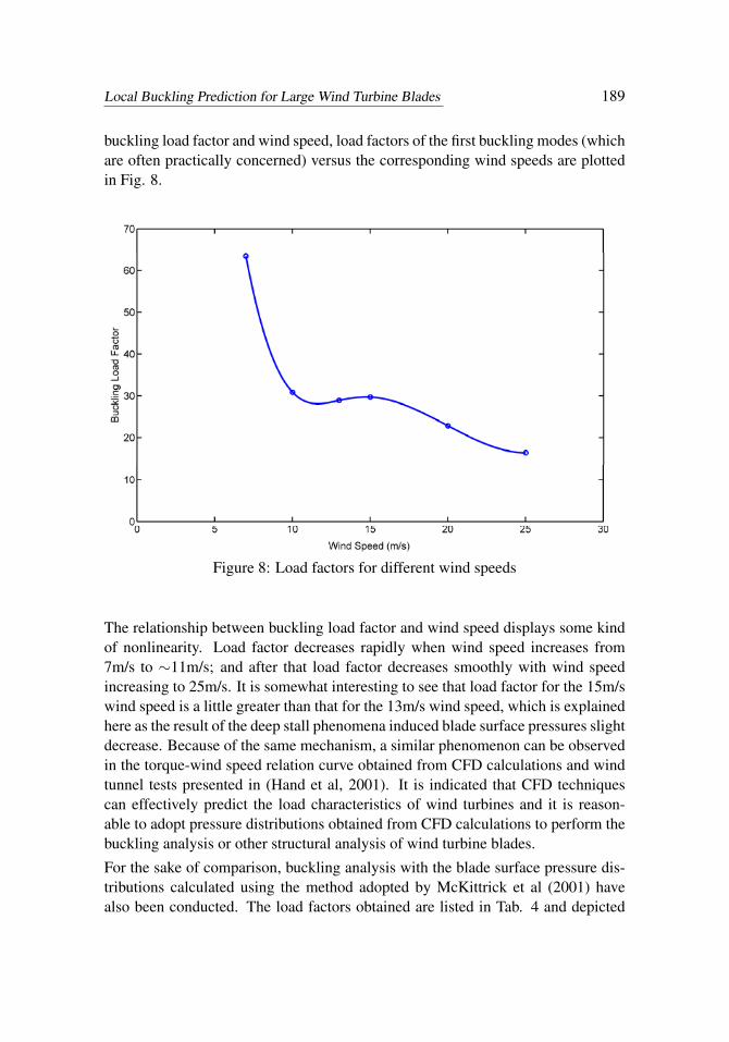
In order to obtain some intuitive knowledge about the complex relation between buckling load factor and wind speed, load factors of the first buckling modes (which are often practically concerned) versus the corresponding wind speeds are plotted in Fig. 8.
Figure 7: Buckling shapes of the (a) 1st, (b) 2nd, (c) 3rd, and (d) 4th bucklingmodes. Wind speed: 15m/s
pressures) increase gradually. The load factors listed in Tab. 3 are all far bigger thanunity, indicating that the blade is safe under those wind speeds.
In order to obtain some intuitive knowledge about the complex relation between
Local Buckling Prediction for Large Wind Turbine Blades 189
buckling load factor and wind speed, load factors of the first buckling modes (whichare often practically concerned) versus the corresponding wind speeds are plottedin Fig. 8.
Figure 8: Load factors for different wind speeds
The relationship between buckling load factor and wind speed displays some kind of nonlinearity. Load factor decreases rapidly when wind speed increases from 7m/s to ~11m/s; and after that load factor decreases smoothly with wind speed increasing to 25m/s. It is somewhat interesting to see that load factor for the 15m/s wind speed is a little greater than that for the 13m/s wind speed, which is explained here as the result of the deep stall phenomena induced blade surface pressures slight decrease. Because of the same mechanism, a similar phenomenon can be observed in the torque-wind speed relation curve obtained from CFD calculations and wind tunnel tests presented in (Hand et al, 2001). It is indicated that CFD techniques can effectively predict the load characteristics of wind turbines and it is reasonable to adopt pressure distributions obtained from CFD calculations to perform the buckling analysis or other structural analysis of wind turbine blades.
For the sake of comparison, buckling analysis with the blade surface pressure distributions calculated using the method adopted by McKittrick et al (2001) have also been conducted. The load factors obtained are listed in Tab. 4 and depicted in Fig. 9 versus the wind speed, compared with the results obtained from previous buckling analysis with CFD loads.
Table 4: Load factors of the first buckling modes from the blade surface pressure
distributions calculated using the method adopted by McKittrick et al (2001).
Wind speed(m/s) 7 10 13 15 20 25
Load factor 938.36 671.02 183.73 82.017 29.426 16.09
Figure 8: Load factors for different wind speeds
The relationship between buckling load factor and wind speed displays some kindof nonlinearity. Load factor decreases rapidly when wind speed increases from7m/s to ∼11m/s; and after that load factor decreases smoothly with wind speedincreasing to 25m/s. It is somewhat interesting to see that load factor for the 15m/swind speed is a little greater than that for the 13m/s wind speed, which is explainedhere as the result of the deep stall phenomena induced blade surface pressures slightdecrease. Because of the same mechanism, a similar phenomenon can be observedin the torque-wind speed relation curve obtained from CFD calculations and windtunnel tests presented in (Hand et al, 2001). It is indicated that CFD techniquescan effectively predict the load characteristics of wind turbines and it is reason-able to adopt pressure distributions obtained from CFD calculations to perform thebuckling analysis or other structural analysis of wind turbine blades.
For the sake of comparison, buckling analysis with the blade surface pressure dis-tributions calculated using the method adopted by McKittrick et al (2001) havealso been conducted. The load factors obtained are listed in Tab. 4 and depicted

190 Copyright © 2011 Tech Science Press CMC, vol.25, no.2, pp.177-193, 2011
in Fig. 9 versus the wind speed, compared with the results obtained from previousbuckling analysis with CFD loads.
Table 4: Load factors of the first buckling modes from the blade surface pressuredistributions calculated using the method adopted by McKittrick et al (2001).
Wind speed(m/s) 7 10 13 15 20 25Load factor 938.36 671.02 183.73 82.017 29.426 16.09
Figure 9: Comparison of Load factors resulted from using CFD loads and reduced
pressure distributions
It is indicated in Tab. 4 and Fig. 9 that load factors calculated using the blade surface pressure distributions calculated using the method in (McKittrick et al, 2001) are incredibly great for low wind speeds (7, 10m/s) and sharply decrease with wind speed increases, approaching the results obtained using CFD loads when wind speed approaches 25m/s. It’s obvious that this kind of simple method cannot obtain accurate blade surface pressure distributions, and therefore cannot yield satisfactory results when the loads from this method are used in structural analysis of the wind turbine blade.
5 Concluding remarks
In this paper, a procedure for predicting the onset and location of local buckling of composite wind turbine blades is developed. In this procedure, CFD techniques are first used to simulate the flow field around a rotating blade of a horizontal axis wind turbine and to obtain the blade surface pressures. Then the finite element method is employed to investigate the onset and location of the local buckling of the composite blade. Between these two steps, an interpolation code is developed to address the mismatch between the unstructured CFD grids of the blade surface and the finite shell elements used during buckling analysis, allowing mapping the pressure computed by using CFD to the finite element model. The procedure is demonstrated with a well documented wind turbine blade and comparison with results obtained by using the pressure distributions in (McKittrick et al, 2001) is also performed. The primary conclusions of this study can be drawn as follows:
The load factors obtained from the buckling analysis are all far bigger than unity, indicating that the blade is safe under the wind speeds considered here. Local buckling located at the maximum chord section of the blade is more likely to occur than global
Figure 9: Comparison of Load factors resulted from using CFD loads and reducedpressure distributions
It is indicated in Tab. 4 and Fig. 9 that load factors calculated using the bladesurface pressure distributions calculated using the method in (McKittrick et al,2001) are incredibly great for low wind speeds (7, 10m/s) and sharply decreasewith wind speed increases, approaching the results obtained using CFD loads whenwind speed approaches 25m/s. It’s obvious that this kind of simple method cannotobtain accurate blade surface pressure distributions, and therefore cannot yield sat-isfactory results when the loads from this method are used in structural analysis ofthe wind turbine blade.

Local Buckling Prediction for Large Wind Turbine Blades 191
5 Concluding remarks
In this paper, a procedure for predicting the onset and location of local bucklingof composite wind turbine blades is developed. In this procedure, CFD techniquesare first used to simulate the flow field around a rotating blade of a horizontal axiswind turbine and to obtain the blade surface pressures. Then the finite elementmethod is employed to investigate the onset and location of the local buckling ofthe composite blade. Between these two steps, an interpolation code is developedto address the mismatch between the unstructured CFD grids of the blade surfaceand the finite shell elements used during buckling analysis, allowing mapping thepressure computed by using CFD to the finite element model. The procedure isdemonstrated with a well documented wind turbine blade and comparison withresults obtained by using the pressure distributions in (McKittrick et al, 2001) isalso performed. The primary conclusions of this study can be drawn as follows:
The load factors obtained from the buckling analysis are all far bigger than unity,indicating that the blade is safe under the wind speeds considered here. Localbuckling located at the maximum chord section of the blade is more likely to occurthan global buckling. Attention should be paid to the thickness of the shell relativeto the length of the blade during the blade design or setting some webs at properpositions.
The buckling load factor and the wind speed have some kind of nonlinear relation.In detail, the load factor decreases rapidly when the wind speed increases from7m/s to ∼11m/s; and after that the load factor decreases smoothly with the windspeed increasing. Here load factor for 15m/s wind speed is a little greater thanthat for the 13m/s wind speed, which is explained here as the result of deeply stallinduced blade surface pressures slight decrease.
CFD techniques can effectively predict the load characteristics of wind turbines andit is reasonable to employ pressure distributions obtained from CFD calculations asload conditions to perform buckling analysis or other structural analysis of windturbine blade. The blade surface pressure distributions obtained from some simplemethods such as the method adopted in (McKittrick et al, 2001) are usually notaccurate, and therefore cannot yield satisfactory results when the loads from thisclass of methods are used in structural analysis of the wind turbine blade.
Acknowledgement: The study presented here is conducted in support of projectsupported by the State Key Development Program for Basic Research of China(Grant No. 2007CB714603). The authors acknowledge all the participants of theproject and their contributions.

192 Copyright © 2011 Tech Science Press CMC, vol.25, no.2, pp.177-193, 2011
References
Baxevanou, C.A.; Chaviaropoulos, P.K.; Voutsinas, S.G.; Vlachos, N.S. (2008):Evaluation study of a Navier-Stokes CFD aeroelastic model of wind turbine airfoilsin classical flutter. Journal of Wind Engineering and Industrial Aerodynamics, vol.96, pp. 1425-1443.
Bir, G. S. (2001): Computerized method for preliminary structural design of com-posite wind turbine blades. Journal of Solar Energy Engineering-Transactions ofthe Asme, vol. 123, no. 4, pp. 372-381.
Cairns, D. S.; Mandell, J. F.; Sears, A.; McKittrick, L. R. (2000): Design con-siderations for buckling in composite wind turbine blades. ASME Wind EnergySymposium, AIAA-2000-0059, ASME/AIAA, pp. 354-366.
Carcangiu, C.E.; Sorensen, J.N.; Cambuli, F.; Mandas, N. (2007): CFD-RANSanalysis of the rotational effects on the boundary layer of wind turbine blades.Journal of Physics: Conference Series, vol. 75, 012031.
Ferrer, E.; Munduate, X. (2007): Wind turbine blade tip comparison using CFD.Journal of Physics: Conference Series, vol. 75, 012005
Hand, M. M.; Simms, D. A.; Fingersh, L. J.; Jager, D. W.; Cotrell, J. R.;Schreck, S. J.; Larwood, S. M. (2001): Unsteady aerodynamics experiment phaseVI: wind tunnel test configurations and available data campaigns. Tech. Rep.NREL/TP-500-29955, NREL.
Hansen, M.O.L.; Sorensen, J.N.; Voutsinas, S.; Sorensen, N.; Madsen, H.A.(2006) State of the art in wind turbine aerodynamics and aeroelasticity. Progress inAerospace Sciences, vol.42, no.4, pp. 285-330.
Hermann, T.M.; Mamarthupatti, D.; Locke, J.E. (2005): Postbuckling analy-sis of a wind turbine blade substructure. Journal of Solar Energy Engineering-Transactions of the Asme, vol. 127, no. 4, pp. 544-552.
Jensen, F.M.; Falzon, B.G.; Ankersen, J.; Stang, H. (2006): Structural testingand numerical simulation of a 34 m composite wind turbine blade. CompositeStructures, vol. 76, pp. 52-61.
Kong, C.; Bang, J.; Sugiyama, Y. (2005) Structural investigation of compositewind turbine blade considering various load cases and fatigue life. Energy, vol. 30,pp. 2101-2114.
Laursen, J.; Enevoldsen, P.; Hjort, S. (2007): 3D CFD quantification of theperformance of a multi-megawatt wind turbine. Journal of Physics: ConferenceSeries, vol. 75, 012007.
Lin, S. M.; Lee, S. Y.; Lin, Y. S. (2008): Modeling and bending vibration ofthe blade of a horizontal-axis wind power turbine. CMES: Computer Modeling in

Local Buckling Prediction for Large Wind Turbine Blades 193
Engineering & Sciences, vol. 23, no. 3, pp. 175-186.
Lund, E.; Johansen, L.S. (2008): On Buckling Optimization of a Wind TurbineBlade. Mechanical Response of Composites, vol. 10, pp. 243-260.
Mandell, J. F.; Samborsky, D. D. (1997): DOE/MSU composite material fatiguedatabase: Test methods, materials, and analysis. Contractor Report SAND97-3002,Sandia National Laboratories, Albuquerque, NM, USA.
McKittrick, L. R.; Cairns, D. S.; Mandell, J.; Combs, D. C.; Rabern, D. A.;Van Luchene, R. D. (2001): Analysis of a Composite Blade Design for the AOC15/50 Wind Turbine Using a Finite Element Method. Tech. Rep. SAND2001-1441,Sandia National Laboratories.
Park, Y.; Chang, B.; Cho, T. (2007): Numerical simulation of wind turbine scaleeffects by using CFD. AIAA paper, no. 2007-2216.
Sezer-Uzol, N; Long, L. N. (2006): 3-D time-accurate CFD simulations of windturbine rotor flow fields. AIAA paper, no. 2006-0394.
Shokrieh, M.M.; Rafiee, R. (2006): Simulation of fatigue failure in a full com-posite wind turbine blade. Composite Structures, vol. 74, no. 3, pp. 332-342.
Spalart, P.R.; Allmaras, S.R. (1994): A one-equation turbulence model for aero-dynamic flows. La Recherche Aerospatiale, no. 1, pp. 5–21.
Walter, D; Musial, B. B.; Scott D. H.; Zutec, M. D. (2001): Four-Point BendingStrength Testing of Pultruded Fiberglass Wind Turbine Blade Sections, AWEA’sWINDPOWER 2001 Conference, Washington, D.C..
Zienkiewicz, O.C. (1989): The Finite Element Method. McGraw-Hill.
