log of revisions - beechcraft · emergency crash axe and/or ... 3 1 thru 8 added log of revisions,...
TRANSCRIPT

2 of 10 P/N 130-590031-145
LOG OF REVISIONSSuper King Air® B200 & B200C
(BB-1834, BB-1843 thru BB-1987, except BB-1978; BL-148 thru BL-151)
Super King Air® B200GT & B200CGT(BY-1 and After; BZ-1 and After; and Airplanes with Kit 101-9113)
Super King Air® 350, 350ER, 350i, 350iER, 350C & 350CER
(Models B300 & B300C)(FL-1 and After; FM-5 and After; FN-1 and After)
Pilot’s Operating Handbookand
FAA Approved Airplane Flight Manual Supplement
for theEmergency Crash Axe and/or
Fairchild FA2100 Cockpit Voice Recorder and/orArtex 110-406 or Artex C406-2 Emergency Locator
Transmitter (ELT) System
REV NO.
PAGE NO(S).
DESCRIPTIONDATE OF
REV
0 1 thru 8 Original Issue March, 2000
1 1 thru 8 Revised Heading and ELT information Nov, 2000
2 1 thru 8 Revised Title Page and added ELT information
April, 2001
3 1 thru 8 Added Log of Revisions, revised Cockpit Voice Recorder information, and shifted data
June, 2002
4 1 thru 8 Added 130-590031-181 POH/AFM to the Title Page
Sept, 2003
5 1 thru 8 Added 101-590010-425 and130-590031-235 effectivity to the Title Page and re-dated all pages.
August, 2006
6 1 thru 8 Added 130-590031-245 effectivity to the Title Page, changed Raytheon Aircraft Company to Hawker Beechcraft Corporation, editorial changes and redated all pages.
March, 2009
7 1 thru 8 Added 101-590168-1 effectivity and 350i and 350iER to the Title Page and EMERGENCY CRASH AXE, and redated all pages.
March, 2010
130-590031-145R8_lor.fm Page 2 Monday, July 28, 2014 1:54 PM
3 of 10
Log Of Revisions (Cont’d)P/N 130-590031-145
Revision 8 - July, 2014
P/N 130-590031-145
8 1 thru 10 Revised Hawker Beechcraft Corporation to Beechcraft Corporation and added the 130-590031-499 POH/AFM to the supplement applicability. Redated all pages, shifted data and updated Contents to reflect the shifted data.
July, 2014
REV NO.
PAGE NO(S).
DESCRIPTIONDATE OF
REV
130-590031-145R8_lor.fm Page 3 Monday, July 28, 2014 1:54 PM

FAA Approved
P/N 130-590031-145
FT BLANK
Revised: July, 2014
130-590031-145R8_text.fm Page 4 Monday, July 28, 2014 1:28 PM
4 of 10
THIS PAGE INTENTIONALLY LE
5 of 10
CONTENTSSECTION 1 - GENERAL . . . . . . . . . . . . . . . . . . . . . . . . . . . . . . . . . . . . . . Page 5
SECTION 2 - LIMITATIONS . . . . . . . . . . . . . . . . . . . . . . . . . . . . . . . . . . . Page 5
SECTION 3 - EMERGENCY PROCEDURES . . . . . . . . . . . . . . . . . . . . . . Page 6
. . . . . . . . . . . . . . Page 6
. . . . . . . . . . . . . . Page 6
. . . . . . . . . . . . . . Page 7
IST . . . . . . . . . . . Page 7
. . . . . . . . . . . . . . Page 7
CE . . . . . . . . . . Page 10
material and must beApproved Airplane Flightgency Crash Axe and/or110-406 or Artex C406-2ordance with Beechcraft
to the basic Pilot’s Oper-anual only as set forth
o always refer to the sup-rding applicable to opera-
130-590031-145R8_text.fm Page 5 Monday, July 28, 2014 1:28 PM
FAA Approved
P/N 130-590031-145
SECTION 3A - ABNORMAL PROCEDURES . . . . . . . .
SECTION 4 - NORMAL PROCEDURES. . . . . . . . . . . .
SECTION 5 - PERFORMANCE. . . . . . . . . . . . . . . . . . .
SECTION 6 - WEIGHT AND BALANCE/EQUIPMENT L
SECTION 7 - SYSTEMS DESCRIPTION . . . . . . . . . . .
SECTION 8 - HANDLING, SERVICING & MAINTENAN
SECTION 1 - GENERAL
The information in this supplement is FAA approvedattached to the Pilot’s Operating Handbook and FAA Manual when the airplane is operating with an EmerFairchild FA2100 Cockpit Voice Recorder and/or Artex Emergency Locator Transmitter (ELT) System in accCorporation approved data.
The information in this supplement supersedes or addsating Handbook and FAA Approved Airplane Flight Mwithin this document. Users of the manual are advised tplement for possibly superseding information and placa
tion of the airplane.
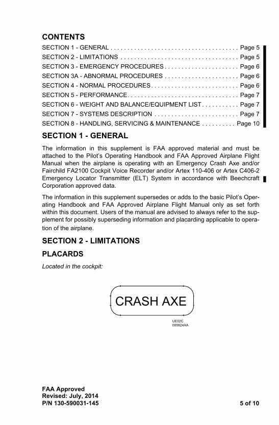
SECTION 2 - LIMITATIONS
PLACARDS
Located in the cockpit:
CRASH AXEUE02C 000824AA
Revised: July, 2014
FAA Approved
P/N 130-590031-145
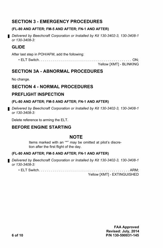
SECTION 3 - EMERGENCY PROCEDURES
(FL-80 AND AFTER; FM-5 AND AFTER; FN-1 AND AFTER)
Delivered by Beechcraft Corporation or Installed by Kit 130-3402-3, 130-3408-1or 130-3408-3:
. . . . . . . . . . . . . . . . . ON;Yellow [XMT] - BLINKING
S
FTER)
it 130-3402-3, 130-3408-1
t pilot’s discre-
FTER)
it 130-3402-3, 130-3408-1
. . . . . . . . . . . . . . . . ARM; [XMT] - EXTINGUISHED
Revised: July, 2014
130-590031-145R8_text.fm Page 6 Monday, July 28, 2014 1:28 PM
6 of 10
GLIDE
After last step in POH/AFM, add the following:
• ELT Switch. . . . . . . . . . . . . . . . . . . . . . . . . . . . . .
SECTION 3A - ABNORMAL PROCEDURE
No change.
SECTION 4 - NORMAL PROCEDURES
PREFLIGHT INSPECTION
(FL-80 AND AFTER; FM-5 AND AFTER; FN-1 AND A
Delivered by Beechcraft Corporation or Installed by Kor 130-3408-3:
Delete reference to arming the ELT.
BEFORE ENGINE STARTING
NOTEItems marked with an “*” may be omitted ation after the first flight of the day.
(FL-80 AND AFTER; FM-5 AND AFTER; FN-1 AND A
Delivered by Beechcraft Corporation or Installed by Kor 130-3408-3:
• ELT Switch. . . . . . . . . . . . . . . . . . . . . . . . . . . . . . Yellow
7 of 10
(FL-30, FL-52, FL-62, FL-63, FL-65, FL-73, FL-84, FL-87, FL-114 AND AFTER)
Delivered by Beechcraft Corporation or Installed by Kit 130-3407-1:
1. Battery . . . . . . . . . . . . . . . . . . . . . . . . . . . . . . . . . . . . . . . . . . . . . . . . . . ON
2. Cockpit Voice Recorder . . . . . . . . . . . . . . . . . . . . . . . . . . . . . . . . . .CHECK
. PLUG INTO CVR JACK
LD (5 seconds minimum)
uld be heard in the head-
UIPMENT LIST
978; BL-148 THRU BL-
LANES WITH KIT 101-
30-5300-1:
side of the right forwardleather cover and has aned to punch holes in the designed to cut or split
130-590031-145R8_text.fm Page 7 Monday, July 28, 2014 1:28 PM
FAA Approved
P/N 130-590031-145
* a. Headset . . . . . . . . . . . . . . . . . . . . . . . . . . . . . .
b. CVR Test Button . . . . . . . . . PRESS AND HO
* • Listen for test tone in headset.
• Observe meter needle in green band.
* c. Speak into area mic on glareshield. Voice shoset.
SECTION 5 - PERFORMANCE
No change.
SECTION 6 - WEIGHT AND BALANCE/EQ
No change.
SECTION 7 - SYSTEMS DESCRIPTION
CABIN FEATURES
EMERGENCY CRASH AXE
(BB-1834, BB-1843 THRU BB-1987, EXCEPT BB-1151)
(BY-1 AND AFTER; BZ-1 AND AFTER; AND AIRP9113)
(FL-1 AND AFTER)
Delivered by Beechcraft Corporation or Installed by Kit 1
When installed, the crash axe is located on the forwardcabin partition. It is secured to the partition by a heavy insulated rubber handle. One side of the axe is designmetal skin of the airplane. The other side of the axe isopenings to exit the airplane.
Revised: July, 2014
FAA Approved
P/N 130-590031-145
AVIONICS SYSTEM
COCKPIT VOICE RECORDER (CVR)
(FL-30, FL-52, FL-62, FL-63, FL-65, FL-73, FL-84, FL-87, FL-114 AND AFTER)
130-3407-1:
ild Model FA2100 cockpit010) or a 2-hour (Model
r, a control unit, an areahe recorder is provided bylocated in the aft avionicscated in the cockpit ped-dge of the glareshield to
r sources:
er the cabin pager.)
mits over the boom mic,
over the boom mic, hand
ded audio data in one of
o recorded by the abovennels. Additionally, whenof audio recorded by theality format on two chan-
r audio data.
h, indicating meter, andide a test of the recorder. audio data that is beingr is receiving the properthe following indications if
Revised: July, 2014
130-590031-145R8_text.fm Page 8 Monday, July 28, 2014 1:28 PM
8 of 10
Delivered by Beechcraft Corporation or Installed by Kit
Airplanes equipped with an L3 Communications Fairchvoice recorder have either a 30-minute (Model 2100-12100-1020) capacity.
The CVR system consists of a cockpit voice recordemicrophone, and an impact switch. Electrical power to tthe triple-fed bus. The recorder and impact switch are bay behind the pressure bulkhead. The control unit is loestal. The area microphone is located in the leading ethe right of the fire extinguisher switch.
Input to the CVR recorder comes from the following fou
• Cabin Pager (What the pilot or copilot transmit ov
• Copilot’s Audio (What the copilot hears or transhand mic, or oxygen mask mic.)
• Pilot’s Audio (What the pilot hears or transmits mic, or oxygen mask mic.)
• Area Mic
The CVR recorder is capable of reproducing the recorthe following formats:
Both CVRs will reproduce the last 30 minutes of audichannels in a high quality format on four separate chaCVR Model 2100-1020 is installed, the last 2 hours above channels may be reproduced in a standard qunels, which contain the following material:
• A combination of the pilot, copilot, and cabin page
• Area Mic audio data.
The control unit contains the test switch, erase switcheadset jack. The test switch and indicating meter provThe headset jack provides a means of monitoring allinput to the CVR recorder to ensure that the recordeaudio signals. Pressing the test switch should result in the recorder is functioning properly:

9 of 10
A delayed one- to two-second tone will be heard in the headset (if pluggedinto the control unit) when the test switch is pressed and held. The tone willthen stop and the needle will move into the green arc on the meter and staythere as long as the switch is pressed.
The erase switch may be used to erase the entire recording after a routine flight,e weight of the airplane isime delay circuit makes its to start the erasure pro-er erasure is indicated by is released. The tone will
LT) WITH REMOTE
TER)
130-3402-3, 130-3408-1
r Transmitter (ELT) Sys-of TSO C91a and C126.rt horn located in the aft and a remote switch withll next to the OAT gage.t the ELT has been acti-d the ON positions. Nei-
er can be positioned to. The system is indepen-it light, which is hot-wiredis controlled by the side
transmit a sweeping tone6.025 MHz is also trans-etermining airplane loca-h setting or availability of
the following functions:
ivated by the “G” switch.
ff-airport landing is antici-
impact did not automati-
wing procedures. Testingll shorten the battery life.
130-590031-145R8_text.fm Page 9 Monday, July 28, 2014 1:28 PM
FAA Approved
P/N 130-590031-145
and will only work when the landing gear is down and thon the landing gear. To prevent accidental erasures, a tnecessary to hold the erase switch down for two secondcess. If a headset is plugged into the control unit, a propa tone in the headset that occurs when the erase switchlast for approximately 5 seconds.
EMERGENCY LOCATOR TRANSMITTER (ESWITCH
(FL-80 AND AFTER; FM-5 AND AFTER; FN-1 AND AF
Delivered by Beechcraft Corporation or Installed by Kitor 130-3408-3:
The Artex 110-406 or Artex C406-2 Emergency Locatotem, if installed, is designed to meet the requirements The system consists of the ELT transmitter and an alefuselage area, an antenna mounted on the aft fuselage,a yellow transmit light located on the left cockpit sidewaThe purpose of the alert horn is to notify personnel thavated. The remote switch is lever-locked in the ARM anther this switch nor the switch on the ELT transmittprevent the automatic activation of the ELT transmitterdent from other airplane systems except for the transmto the airplane battery, and the edge lit panel, which panel light’s rheostat located on the overhead panel.
Upon activation, the ELT will sound the alert horn and on 121.5 and 243.0 MHz. An additional frequency of 40mitted, which is used by orbiting satellites to assist in dtion. This activation is independent of the remote switcairplane power. The remote switch is installed to perform
• Test the ELT.
• Deactivate the ELT if it has been inadvertently act
• Activate the ELT in an in-flight emergency if an opated.
• Activate the ELT after an off-airport landing, if thecally activate it.
The ELT should be tested once a month using the folloin excess of once a month is not recommended, as it wi
Revised: July, 2014

FAA Approved
P/N 130-590031-145
• Tests should be conducted between the times of on-the-hour until 5 min-utes after the hour.
• Notify any nearby control towers.
NOTE seconds. Theansmissions insignal.
121.5 MHz.
t 3 sweeping tones on the then return the switch to
eard and the transmit light is a delay in the illumina-g properly. The sounding
l ELT test nor is failure ofe.
RM position, the transmitnd and then extinguish. If
em, the transmit light willecond illumination to indi-
ing 1 blink:
blem.
sent. Since the Model . . LT, this coded signal will
ighest priority.
ghest priority to lowest pri-
switch, the alert horn willk. The ELT can be deacti-d then back to ARM.
fer to the Artex Installation
MAINTENANCE
Revised: July, 2014
130-590031-145R8_text.fm Page 10 Monday, July 28, 2014 1:28 PM
10 of 10
Do not allow the test duration to exceed 15satellite system recognizes 406.025 MHz trexcess of 15 seconds to be a valid distress
• Provide power to an airplane radio and tune it to
• Place the ELT remote switch ON. Wait for at leasairplane radio, which will take about 1 second,ARM.
• The test is successful if the sweeping tones are hnext to the switch illuminates immediately. If theretion of the transmit light, the system is not workinof the alert horn does not predicate a successfuthe alert horn to sound an indication of ELT failur
• When the ELT remote switch is returned to the Alight will stay illuminated for approximately 1 secothe microprocessor in the ELT detects a problblink a specific number of times following the 1 scate the following faults:
Listed in order of priority with the highest priority be
1 Blink - Indicates a G-switch loop open failure.
3 Blinks - Indicates a 406.025 MHz transmitter pro
5 Blinks - Indicates there is no navigation data preB300 does not provide navigation data to the Ealways be present.
7 Blinks - Indicates a battery problem.
The Artex 110-406 will only indicate the fault with the h
The Artex C406-2 will indicate all faults in order from hiority.
If the ELT should be inadvertently activated by the “G”sound and the transmit light next to the switch will blinvated by momentarily placing the remote switch ON an
For test procedures on the 406.025 MHz frequency, reand Operation Manual.
SECTION 8 - HANDLING, SERVICING &
No change.