long-term stability of pvdf-sio2-hdtms composite hollow
TRANSCRIPT

Long-Term Stability of PVDF-SiO2-HDTMSComposite Hollow Fiber Membrane For CarbonDioxide Absorption in Gas–Liquid ContactingProcessHonglei Pang ( [email protected] )
Nanjing Vocational University of Industry TechnologyYayu Qiu
Nanjing Vocational College of Information TechnologyWeipeng Sheng
Zhejiang Xinchai CO., LTD
Research Article
Keywords: Super hydrophobic membrane, Membrane contactor, Carbon dioxide absorption, Hydrophobicmodi�cation
Posted Date: November 12th, 2021
DOI: https://doi.org/10.21203/rs.3.rs-1006466/v1
License: This work is licensed under a Creative Commons Attribution 4.0 International License. Read Full License
Long-term stability of PVDF-SiO2-HDTMS composite hollow fiber
membrane for carbon dioxide absorption in gas–liquid contacting
process
Honglei Pang a* , Yayu Qiu b*, Weipeng Sheng c
a Nanjing Vocational University of Industry Technology, Nanjing, 210023, PR China
b Nanjing Vocational College of Information Technology, Nanjing, 210023, PR China
c Zhejiang Xinchai CO., LTD, Shaoxing, 312500, PR China
ABSTRACT
To obtain a long-term stable operation of the hollow fiber membrane for using in membrane
contact absorption of carbon dioxide (CO2), hybrid polyvinylidene fluoride-silica-
hexadecyltrimethoxysilane (PVDF-SiO2-HDTMS) membrane were fabricated via the non-solvent
induced phase-inversion method. The surface properties, performance characteristics and long-term
stable operation performance of the prepared membranes were compared and analyzed. The results
show the outer surface of the prepared membranes exhibited superhydrophobicity because of the
formation of rough nano-scale microstructures and the low surface free energy. Due to the addition
of inorganic nanoparticles, the mechanical strength of PVDF-SiO2-HDTMS membranes were
improved. The long-term stable operation experiments were carried out with the inlet gas (CO2/N2
= 19/81, v/v) at a flow rate of 20 mL/min and the absorbent liquid (1 mol/L DEA) at a flow rate of
50 mL/min. And the result showed that the mass transfer flux of PVDF-SiO2-HDTMS membrane
decreased from the initial value of 2.39×10⁻³ mol/m2s to 2.31×10⁻³ mol/m2s, which was a decrease
of 3% after 20 days. The main benefit is the addition of inorganic nanoparticles, which have strong
chemical resistance and high hydrophobicity, thereby preventing structural damage and pore wetting
of the membrane. PVDF-SiO2-HDTMS membrane exhibits excellent long-term stable operation
performance of CO2.
Keywords: Super hydrophobic membrane; Membrane contactor; Carbon dioxide absorption;
Hydrophobic modification
*
* Corresponding author.
E-mail address: [email protected] (H. Pang), [email protected](Y., Qiu)

1 Introduction
Biogas is a promising renewable energy source [1]. Usually, it is mainly composed of CH4 (55-
65%), CO2 (30-45%) [2] and other trace gases. In order to use it as a fuel gas, the content of CH4
should be as high as 95%, so the absorption of carbon dioxide (CO2) is of great significance to the
practical application of biogas. Carbon dioxide (CO2) capture from biogas by the hollow fiber
membrane contactor system have been investigated by several researchers. In a membrane contactor
system for CO2 absorption, the mixed gas and the liquid absorbent respectively flow on both sides
of the hollow fiber membrane, and the CO2 in the gas is absorbed by the liquid absorbent after
passing through the hollow fiber membrane. The hollow fiber membrane acts as a non-selective
interface barrier between the liquid phase and the gas phase, which separates the gas phase from the
liquid phase and provides a large gas-liquid contact area. The studies have shown that in the process
of membrane contact absorption, the absorption liquid will enter the membrane pores [3-5], causing
the membrane pores to be wetted. Because the diffusion rate of CO2 in the gas is greater than that
of the liquid phase, it will cause the resistance of diffusion of CO2 in the membrane to be greatly
increased and which resulting in a rapid decrease in the mass transfer flux of CO2. Therefore, the
hollow fiber membrane must be hydrophobic.
In the long-term operation process of membrane contact absorption, it is inevitable that the
membrane will be wetted. On the one hand, it is because the pressure of the liquid phase must be
higher than the pressure of the gas phase during the membrane contact absorption process to avoid
the generation of bubbles. Therefore, the absorbent enters the membrane pores driven by the
transmembrane pressure difference, which will cause the pores to wet; On the other hand, when a
chemical absorbent is used, the surface properties (pore size, porosity, roughness and chemical
composition etc.) of the membrane will change due to the polymer membrane material being
susceptible to erosion by alkaline liquid[6-8], the pore size of the membrane will increase and the
surface contact angle will decrease, so the hydrophobicity of the membrane will decrease. In
addition, during long-term operation, the vapor of the absorption liquid will enter the membrane
pores, and the condensation of water vapor in the membrane pores can also cause the membrane
pores to gradually wet. Therefore, the long-term stability of hollow fibers should be verified to
determine whether they are indeed suitable for use in industry. Therefore, the development of long-
term stable operation of superhydrophobic hollow fiber membranes has become a hot spot in the

research of membrane contact absorption in recent years [9,10].
In our previous studies[15], the hybrid polyvinylidene fluoride-hexadecyltrimethoxysilane
(PVDF-HDTMS) membranes with the super hydrophobic outer surface were prepared through the
simple non-solvent induced phase-inversion method, that because the outer surface of modified
membranes possess low surface free erengy and uneven surface. The PVDF-HDTMS membranes
have the excellent long-term stability which the CO2 mass transfer flux was decreased by only 17%
after 17 days of the long-term contact absorption experiment( 1 mol/L DEA as the absorbent ),but
its long-term stability can still be improved compared with the existing research.
Studies have shown that using special methods to deposit hydrophobic inorganic nanoparticles
on hollow fiber membranes can obtain superhydrophobic hollow fiber membranes with strong long-
term stability [11,12]. Zhang et al. [13] developed a highly hydrophobic organic-inorganic
composite hollow fiber membrane by incorporating a fluorinated silica inorganic (fSiO2)layer on a
polyetherimide (PEI) organic membrane substrate via sol-gel process. The membrane contactor
showed a reasonable stability throughout the 31 days operation with 20% drop of the initial CO2
flux with using a 2M aqueous sodium taurinate solution as the absorbent. This is mainly due to the
fact that the incorporation of the fSiO2 inorganic layer offered high hydrophobicity and protected
the polymeric substrate from the attacks of chemical absorbents, making the membrane a longer
lifespan. Yilin Xu et al. [14] fabricated an inorganic-organic fluorinated titania-silica (fTiO2-
SiO2)/polyvinylidene fluoride (PVDF) composite membrane by forming a superhydrophobic SiO2-
TiO2 inorganic layer on the PVDF membrane substrate via facile in-situ vapor-induced
hydrolyzation method followed by hydrophobic modification. The CO2 absorption flux of fTiO2-
SiO2/PVDF composite hollow fiber membrane decreased by merely 10% over the 31days long-term
test due to its high chemical resistance and hydrophobicity that effectively prevented the PVDF
substrate from corrosion by chemical absorbents of MEA. Therefore, the introduction of
hydrophobic inorganic nanoparticles into the hollow fiber membrane can not only increase the
hydrophobicity of the membrane, but also improve the high chemical resistance of the membrane,
and ultimately the long-term performance of the membrane can be improved.
In this study, we aim to design and fabricate the polyvinylidene fluoride-silica-
hexadecyltrimethoxysilane (PVDF-SiO2-HDTMS) composite membrane via the simple non-solvent
induced phase-inversion method with ammonia water as the non-solvent additive and

dehydrofluorination reagent, and HDTMS as the hydrophobic modifier, and the nano-SiO2 particles
as the inorganic filler. The physical and chemical properties of the prepared PVDF-SiO2-HDTMS
film were characterized, and the long-term stability of CO2 was detected by using DEA as an
absorbent.
2. Experimental
2.1. Materials
PVDF L-6020 in the form of pellet particle was purchased from Solvay Advance Polymers,
USA, and used for the fabrication of the hollow fiber membranes. The reagents of N-methyl-2-
pyrrolidone (NMP, ≥99.0% purity), ammonia water (25–28% purity, pH =12–13), diethanolamine
(DEA, 99.0% purity), and ethanol (≥99.7% purity) were supplied by Chengdu Kelong Inc., China.
HDTMS was supplied by Aladdin Inc., China. Nano-SiO2 particles(The average particle size of is
50 nm,Hydrophilic)were supplied by Shanghai Macklin Biochemical Co., Ltd., China.
2.2 Fabrication of hollow fiber membrane and membrane contactor module[15][19]
In this study, the PVDF-SiO2-HDTMS hollow fiber membranes were fabricated via dry-jet
wet-spinning phase inversion method. The PVDF and SiO2 were dried in a vacuum oven at 70±2°C
for 24h, the dehydrated PVDF polymer particles were added into NMP, ammonia water and SiO2
mixture gradually and stirred by a magnetic stirrer at 60°C until the particles were completely
dissolved, in this process, the solution gradually turned to brown. After the solution was allowed to
stand for 12 h, the HDTMS was added into this solution, and then it was stirred at room temperature
for another 12 h to form a homogenous dope. The dope was degassed under vacuum overnight
before spinning. The compositions of each dope in this study are shown in Table 1. The parameters
of the spinning process are shown in Table 2. The spinning process is shown in Figure 1. The
fabricated hollow fiber membranes were immersed in pure ethanol for 15 min at first after spinning
process, and subsequently stored in water for 3 days to remove NMP and additives, and then
immersed in methanol for 1 day to protect the formed pore. At last, the membranes were kept at
room temperature to evaporate the residual methanol.
Table 1
Polymer dope composition.
Membrane NMP PVDF Ammonia HDTMS SiO2 External Bore liquid

(g) (g) (g) (g) (g) coagulant
PVDF-SiO2-HDTMS 80 20 1 1.5 1.5 Ethanol Distilled Water
PVDF -HDTMS 80 20 1 1.5[15] 0 Ethanol Distilled Water
Table 2
Hollow fiber spinning parameters.
Spinning parameter Value
Dope extrusion rate (ml/min) 4.5
Bore liquid (wt. %) Distilled water
Bore liquid flow rate (ml/min) 1.7
Air gap distance (cm) 0
Spinneret (od/id) (mm) 1.6/0.8
Spinneret wall thickness (mm) 0.3
Spinning dope temperature (℃) 25
Coagulant temperature (℃) 25
Bore liquid temperature (℃) 25
Fig. 1 The preparation device of hollow fiber membrane.
2.3. Characterization
The surface functional groups of the membranes were determined by the attenuated total
reflectance-Fourier transform infrared spectroscopy (ATR-FTIR) on a NEXUS 870, NICOLET,
USA[15]. The ATR-FTIR spectra were collected over a scanning range of 500-4000 cm‒1 with 16
scans over 4.0 cm−1.

The morphology images of the hollow fibers were observed by the scanning electron
microscopy (SEM) instrument Tabletop Microscope FEI Quanta 250 FEG, USA[19]. The cross
section was obtained by fracturing each membrane in liquid nitrogen. The samples were sputtered
with gold for 15 s at 40 mA current before the test [15].
A sessile drop technique using a goniometer (Shanghai Zhongchen Digital Technology
Instrument Corporation Limited, JC2000D1, China) was used to measure the contact angles of the
outer surface of the membranes[19]. For each measurement, 3 μL of pure water or 1M DEA was
pumped out from a syringe. The liquid drop remained on the membrane outer surface for 3 min
before recording, and the result was adopted as the average value of ten measurements for each
sample[15].
The nitrogen (N2) gas permeation test was conducted to obtain the mean pore size and effective
surface porosity. The wettability resistance of the prepared membrane was assessed by
measurements of the critical water entry pressure (CEPw). The measurement method of the nitrogen
(N2) gas permeation and CEPw were referred to literature [15-17].
2.4 CO2 contact absorption experiment
CO2 absorption experiments process and the experimental setup could refer to our previous
study [15]. The corresponding parameters for the experiments are shown in Table 3. Before each
test, the system was operated for at least 30 min to obtain a steady state. The CO2/N2 mixture (19
vol.% CO2) was served as the feed gas flowing through the lumen side of the membranes, and the
aqueous DEA solution of 1 mol/L was employed as the liquid absorbent flowing through the shell
side of the membranes counter-currently. The flowrate of inlet gas was controlled at 20 mL/min by
a gas rotameter, and the flowrate of absorption liquid was controlled by a constant flow pump at 50
mL/min. In order to prevent gas bubbles into the liquid phase, the pressure in the liquid side was
controlled 20 kPa higher than that in the gas side. The concentrations of CO2 in the inlet and outlet
gas were measured by the CO2 detector (MIC-800, Shenzhen Yiyuntian electronics technology Co.
Ltd., China). The equation to calculated CO2 absorption flux of the PVDF membranes referred to
our previous article [15].
Table 3
Characteristics of membrane contactors.

Parameter Value
Module length (mm) 200
Module inner diameter (mm) 8
Effective fiber length (mm) 150
Number of fibers 4
Fiber inner diameter (mm) 0.6-0.7
Fiber outer diameter (mm) 1.1-1.2
Gas-liquid flow
Counter-current flow,gas through the
lumen,liquid through the shell
3. Results and discussion
3.1. Formation mechanism of the PVDF-SiO2-HDTMS membranes
The PVDF-SiO2-HDTMS membranes were fabricated in four steps. The First step The first
step was to introduce oxygen-containing functional groups into PVDF molecules through
defluorination and oxygenation reactions, which had been explained thoroughly in our previous
works[18](Fig. 2). In the second step, the hydroxyl groups on the PVDF chain reacted with most of
the hydroxyl groups on the surface of SiO2, they were connected by -O- bonds. After the reaction
was over, the dope of PVDF-SiO2 is formed. In the three step, the HDTMS was added into the
polymer solution, it was hydrolyzed by the small amount of water in the solution to form silanol,
and then polycondensation occurred between the silanol molecules to form polysiloxane. The
polysiloxane then reacted with the hydroxyl groups on PVDF-SiO2.The mechanism of HDTMS
grafting onto PVDF-SiO2 is shown in Fig. 3, R represents hexadecyl group. Finally, PVDF-SiO2-
HDTMS hollow fiber membranes were fabricated through the non-solvent induced phase-inversion
process.

Fig. 2 The reaction pathways of dehydrofluorination on PVDF chains via alkaline treatment [18].
Si
OCH3
R
OCH3
OCH3 Si
OH
R
OH
OH 3CH3OH
R CH3(CH2)15
Hydrolysis
Si
OH
R
OH
OHnnH2O
SiOH
R
OH
OH
n
Condensation
OH OHSiO2 SiOH
R
OH
OH
nPVDF chains
O
SiO2
O
SiO2
O
SiHO
R
H
x
O
O
SiHO
R
H
y
O
Grafting
Fig. 3 Mechanism of forming the PVDF-SiO2-HDTMS chains.
3.2. Membrane surface chemical structure
4000 3500 3000 2500 2000 1500 1000 500
20
40
60
80
100
120
140
160
180
200
28492917
% R
efle
ctan
ce
Wavenumbers(cm-1)
PVDF-SiO2-HTDMS-1.5
PVDF-HTDMS-1.5
PVDF-PA-8
Fig.4 ATR-FTIR spectra of the membranes.

ATR-FTIR spectra of the fabricated membranes and PVDF-PA-8 membrane (without any
grafting treatment in our previous works[19]) outer layers are presented in Fig. 4. Compared with
the PVDF-PA-8 membrane, two new bands were observed at 2917 and 2849 cm-1 in the ATR-FTIR
spectrum of the PVDF-SiO2-HDTMS and PVDF-HDTMS membrane outer layers, which could be
ascribed to the stretching of methylene groups (CH2) in the HDTMS chain. It shows that HDTMS
has been successfully grafted on the outer surface of PVDF-SiO2-HDTMS film and PVDF-HDTMS
membranes. The absence of Si-O-Si functional group spectra on the outer surface of the PVDF-
SiO2-HDTMS membrane may be caused by the coincidence of its characteristic band with the
characteristic band of PVDF.
3.3 Morphology of a hollow fiber membrane
SEM images of the prepared hollow fiber membranes and PVDF-PA-8 membrane are shown
in Fig. 4. For PVDF, a semi-crystalline polymer, in the process of preparing hollow fiber membranes
by the wet method, the final form of the membrane is mainly formed by liquid-liquid stratification
or solid-liquid stratification. The bath conditions play a decisive role in the membrane
structure[20,21]. In the preparation process of PVDF-SiO2-HDTMS membrane and PVDF-HDTMS
membrane, pure ethanol was used as the external coagulation bath, and water was used as the core
fluid. The PVDF-PA-8 membrane was used water and 80% NMP aqueous solution as the external
coagulation bath and the core fluid respectively. It could be observed in Fig. 2 that the PVDF-SiO2-
HDTMS membrane and PVDF-HDTMS membrane have no outer skin layer but an inner skin layer,
and the outer surface of the PVDF-SiO2-HDTMS membrane and PVDF-HDTMS is mainly
composed of spherulitic structures, while the inner and outer skin structures of PVDF-PA-8 are just
the opposite. This is mainly due to the use of “soft” pure ethanol and 80% NMP aqueous solution
to act as the coagulation bath. In the process of spinning, the exchange rate between solvent and
non-solvent is lower during the phase transfer, which is lower than after the polymer crystallization
process, so solid-liquid stratification accounts for Lead to form a spherulite structure.

Fig. 5 SEM images of the hollow fiber membranes. (a) PVDF-SiO2-HDTMS; (b) PVDF-HDTMS;
(c) PVDF-PA-8
Further observation found that the out surface of PVDF-HDTMS membrane is composed of
honeycomb spherulitic structure(Fig.5b), however, the spherulite structure of the PVDF-SiO2-
HDTMS membrane out surface is covered with lumpy substance materials(Fig.5a), which may be
caused by the accumulation of a large amount of SiO2.
PVDF is hydrophobic, nano SiO2 is hydrophilic, the blending of the two will cause poor
dispersion of SiO2 in the casting solution and the agglomeration of SiO2 will occur, that is because
the interfacial tension between the hydrophobic and hydrophilic inorganic materials [22]. It can be
found from fig.5, the SiO2 distribution on the cross section of the PVDF-SiO2-HDTMS membrane

is uniform, and a large amount of agglomeration is not found. This is due to the introduction of
hydroxyl groups into the PVDF chains under the action of ammonia water [22], which resultes in
the enhanced affinity between PVDF chains and the hydrophilic nanoSiO2 particles.
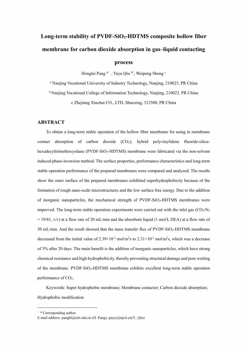
3.4. Gas permeability and hydrophobicity of the hollow fiber membranes
The gas permeability of the fabricated membranes was inspected by N2 permeation test. The
N2 permeation test of the fabricated membranes and the PVDF-PA-8 membranes are shown in Fig.6.
As shown in Fig. 6, PVDF-PA-8 membrane shows the lowest N2 permeability, which is mainly due
to the large number of sponge-like structures in the cross-section, resulting in greater tortuosity in
the cross-section of the membrane than the other two membranes [23]. The nitrogen permeability
of the membrane decreased because of the addition of inorganic nanoparticles which could blocked
the membrane pores, so the N2 permeability of the PVDF-SiO2-HDTMS membrane was slightly
lower than that of the PVDF-HDTMS membrane. The calculation methods of effective surface
porosity and average pore size have been introduced[24][25]. The values of effective surface
porosity and average pore size of the membranes are shown in Table 4. It could be found that the
surface pore size and surface porosity of PVDF-SiO2-HDTMS and PVDF-HDTMS membranes are
higher than those of PVDF-PA-8, which is because the open membrane structure without outer skin,
which can provide larger pore size and surface porosity. The parameters of CEPW and outer surface
contact angle, which are correlated to the long-term stability of the membranes, are also shown in
Table 4. Compared with PVDF-HDTMS membrane, PVDF-SiO2-HDTMS membrane has
significantly higher CEPW and higher outer surface contact angle. Therefore, PVDF-SiO2-HDTMS
membrane is more conducive to the application of CO2 absorption in membrane contactors.
During the preparation process, the strength of PVDF chain would be decreased due to
defluorination. As a result, the fabricated membranes showed decrease in the mechanical strength.
Therefore, as shown in Table 4, the tensile strength and elongation at break of PVDF-SiO2-HDTMS
and PVDF-HDTMS membranes are lower than those of PVDF-PA-8 membrane. However, the
tensile strength and elongation at break of PVDF-SiO2-HDTMS membrane are higher than that of
PVDF-HDTMS membrane. This is mainly due to the formation of Si-O-Si bonds between SiO2 and
PVDF and between SiO2 and HDTMS, which enhances the molecular bonding force between the
three, thereby increasing the tensile strength and elongation at break of the PVDF-SiO2-HDTMS
membrane.
100 150 200 250 300 350
1.0x10⁻⁶
2.0x10⁻⁶
3.0x10⁻⁶
N2 P
emea
nce
(mo
l/m
2 s
Pa)
Mean Pressure(Pa)
PVDF-PA-8
PVDF-SiO2-HDTMS-1.5
PVDF-HDTMS-1.5
Fig.6 N2 permeance of the hollow fiber membranes
Table 4 Characteristics of the hollow fiber membranes.
Membrane Mean pore
size (nm)
Effective
surface porosity
(m−1)
Elongation
at
break(%)
Tensile
strength
(MPa)
CEPW
(×105)
(Pa)
Contact
angle (◦)
(water)
Contact
angle (◦)
(DEA)
PVDF-SiO2-
HDTMS-1.5
20.21 338.8 25±0.4 3.2±0.3 9±0.5 160±0.2 160±0.2
PVDF-HDTMS-1.5 38.93 404.8 15±0.3 1.7±0.3 7.5±0.5 150.0±0.3 146.5±0.5
PVDF-PA-8 17.40 113.1 46.4±0.9 4.1±0.3 9.0±0.5 78.6±0.4 71.5±0.5
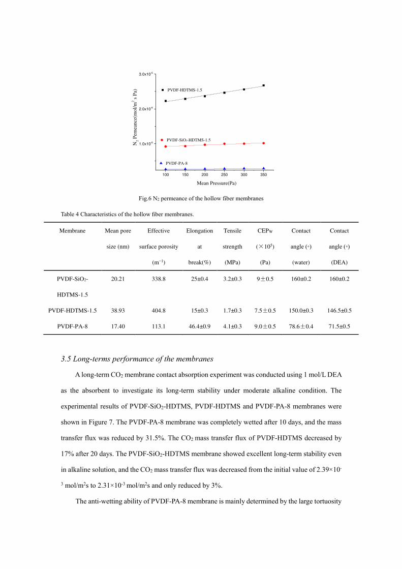
3.5 Long-terms performance of the membranes
A long-term CO2 membrane contact absorption experiment was conducted using 1 mol/L DEA
as the absorbent to investigate its long-term stability under moderate alkaline condition. The
experimental results of PVDF-SiO2-HDTMS, PVDF-HDTMS and PVDF-PA-8 membranes were
shown in Figure 7. The PVDF-PA-8 membrane was completely wetted after 10 days, and the mass
transfer flux was reduced by 31.5%. The CO2 mass transfer flux of PVDF-HDTMS decreased by
17% after 20 days. The PVDF-SiO2-HDTMS membrane showed excellent long-term stability even
in alkaline solution, and the CO2 mass transfer flux was decreased from the initial value of 2.39×10-
3 mol/m2s to 2.31×10⁻³ mol/m2s and only reduced by 3%.
The anti-wetting ability of PVDF-PA-8 membrane is mainly determined by the large tortuosity
of the membrane cross-section and the small surface pore size. However, its wetting resistance
ability to alkaline solution is poor due to the low hydrophobicity, which leading to its shows poor
long-term stable operation.
PVDF-SiO2-HDTMS membrane and PVDF-HDTMS membrane have similar parameters such
as average pore size, surface effective porosity, surface contact angle, etc., so their anti-wetting
performance and air permeability are similar. In the short-term experiment process, the difference
in the mass transfer flux of the membrane to CO2 was less. However, during long-term operation,
the decline of PVDF-HDTMS membrane is greater than that of PVDF-SiO2-HDTMS membrane,
which may be related to the tensile strength of the membrane, although the tensile strength of PVDF-
HDTMS membrane can be applied to the membrane contact absorption, it is lower than the PVDF-
SiO2-HDTMS membrane, thus leads to alkaline solution erosion during long-term stable operation,
leading to an increase in its decline rate.
0 5 10 15 20
0.8
1.0
1.2
1.4
1.6
1.8
2.0
2.2
2.4
PVDF-SiO2-HDTMS-1.5
PVDF-HDTMS-1.5
PVDF-PA-0.8
CO
2 F
lux(
×1
0-3)
DAY
Fig.7 Long-term CO2 absorption performance of the membranes
3.6 The Chemical stability of the composite membrane
In the process of membrane contact absorption, due to the long-term mutual contact between
the membrane and the chemical absorbent, a chemical reaction occurs between the surface of the
membrane and the chemical absorbent, causing the deterioration of the long-term stability of the
membrane and the decreases of CO2 mass transfer flux of membrane. In order to verify the corrosion
resistance of PVDF-SiO2-HDTMS hollow fiber membranes to chemical absorbents, this study used
nitrogen permeation and contact angle experiments to characterize the performance of hollow fiber

membranes after 20 days long-term stable operation.
The nitrogen test results of the three types of membranes after 20 days long-term operation
were shown in Figure 8. Comparing with Figure 6, it was found that the N2 permeability of the
membranes has not changed significantly. The surface pore size and porosity was obtained by
calculation (Table 5), showing that the surface pore size and porosity of the three types of
membranes had changed large, which indicates that MEA did not have much effect on the surface
morphology of the membranes. It could be found the contact angles of the three types of membranes
had decreased after 20 days long-term operation, and the decrease range was PVDF-SiO2-
HDTMS<PVDF-HDTMS<PVDF-PA-8. According to M. Sadoogh et al. [26] studies, the
degradation of PVDF membrane performance may be due to the chemical degradation of the
interface between PVDF and MEA, which leaded to the dehydrogenation and fluorination of the
PVDF surface. Therefore, the reason for the lower drop of the contact angle of PVDF-SiO2-HDTMS
was the surface of PVDF-SiO2-HDTMS membrane grafted with a large amount of
superhydrophobic SiO2 with high hydrophobicity and chemical stability, which effectively
prevented the PVDF substrate from being in the MEA solution. The corrosion in the medium
ensured the long-term stable operation of the membrane. Yilin Xu et al. [14] prepared a
superhydrophobic f-TiO2-SiO2 layer on the outer surface and Yuan Zhang et al. [13] prepared a
superhydrophobic f-SiO2 layer on the outer surface. The same results were also obtained. Therefore,
it can be shown that grafting superhydrophobic metal nanoparticles on the outer surface of the
membrane can effectively prevent the chemical corrosion of PVDF from chemical absorbents and
increase the chemical corrosion resistance of the membrane.

100 150 200 250 300 350
1.0x10⁻⁶
2.0x10⁻⁶
3.0x10⁻⁶
N2 P
emea
nce
(mol/
m2 s
Pa)
Mean Pressure(Pa)
PVDF-PA-8
PVDF-SiO2-HDTMS-1.5
PVDF-HDTMS-1.5
Fig. 8 N2 permeance of the hollow fiber membranes
Table5 Characteristics of the hollow fiber membranes.
Membrane Mean pore size
(nm)
Effective surface
porosity (m−1)
Contact angle (◦)
(water)
Contact angle (◦)
(DEA)
PVDF-SiO2-HDTMS 21.02 324.6 154±0.2 148±0.2
PVDF-HDTMS 40.63 385.8 142.0±0.3 126.2±0.3
PVDF-PA-8 20.66 96.5 58.5±0.5 43.5±0.5
In Table 6, the PVDF-SiO2-HDTMS membrane was compared with other hydrophobic
membranes reported by other research groups. Its carbon dioxide absorption flux and long-term
stability was listed in Table 6. It could be found that the PVDF-SiO2-HDTMS membrane in this
study exhibits competitive performance in terms of CO2 absorption flux as well as long term stability
in cases of moderate alkaline absorbent and absorbent flowrate, and low CO2 concentration.
Table 6
Comparison of CO2 absorption performance in gas-liquid membrane contactor.
Ref. Membrane
types
CO2 Flux
(mol/m2s )
Inlet gas
type
Absorbent
type
Gas flow
rate
Absorbent
flow rate
Contact
angle (◦)
(water)
27
D-TZ-PAN-
20
1.9×10⁻³ Prue CO2
distilled
water
1500ml/m
in
240ml/min 113±2
28
PVDF+6%S
MM
5.3 ×10⁻³ Pure CO2
distilled
water
100ml/mi
n
300ml/min 99 ± 1.50

14
PVDF+f-
TiO2-SiO2
8.0×10⁻³ Pure CO2 1M MEA
Not
reported
0.25m/s
124(dyna
mic)
This
work
PVDF-SiO2-
HDTMS
2.23×10⁻³ 19% CO2 1M MEA 20ml/min 50ml/min 160±0.2
4. Conclusions
In this study, hydrophilic nano SiO2 was used as an inorganic filler to be added to the casting
solution, and ammonia was used as a defluorinating agent to hydroxylate PVDF molecules under
the action of ammonia to generate active sites; add hydrophilic nano SiO2, The hydroxyl group and
the hydroxyl group formed on the PVDF molecule undergo a dehydration reaction to form a cross-
linked PVDF-SiO2 polymer chain; then HDTMS is added to make it hydrophobically modified; the
superhydrophobic PVDF-SiO2 with high strength is prepared by spinning by the NIPS method
HDTMS organic-inorganic composite membrane. The prepared membrane has a maximum CO2
mass transfer flux of 2.39×10⁻³mol/m2s. After 20 days of membrane contact absorption with 1 mol/L
DEA as the absorbent, the CO2 mass transfer flux of the membrane contactor decreased by only 3%.
Since the surface of PVDF-SiO2-HDTMS film is grafted with a large amount of superhydrophobic
SiO2 with high hydrophobicity and chemical stability, it effectively prevents the corrosion of PVDF
substrate in MEA solution, so PVDF-SiO2-HDTMS is prepared. The film has superhydrophobicity,
the film has the strongest resistance to wetting and chemical stability.
Acknowledgments
The authors gratefully acknowledge the financial supports from the Qing Lan Project of Jiangsu
Province (Nos. 202050220RS005).
[1] P. Weiland. Biogas production: current state and perspectives [J]. Applied Microbiology and
Biotechnology, 2010, 85:849-860. DOI: 10.1007/s00253-009-2246-7.
[2] Y. Xu, X. Li, Y. Lin, C. Maldec, R. Wang. Synthesis of ZIF-8 based composite hollow fiber
membrane with a dense skin layer for facilitated biogas upgrading in gas-liquid membrane

contactor[J]. Journal of Membrane Science, 2019, 585:238-252. DOI:
10.1016/j.memsci.2019.05.042.
[3] Y. Lv, X. Yu, J. Jia, S. T. Tu, J. Yan, E. Dahlquist. Fabrication and characterization of
superhydrophobic polypropylene hollow fiber membranes for carbon dioxide absorption[J].
Applied Energy, 2012,90(1):167-174. DOI: 10.1016/j.apenergy.2010.12.038.
[4] Y. Zhang, J. Sunarso, S. Liu, R. Wang. Current status and development of membranes for
CO2/CH4 separation: A review[J]. International Journal of Greenhouse Gas Control, 2013, 12:84-
107. DOI: 10.1016/j.ijggc.2012.10.009.
[5] S. Khaisri, D. Demontigny, P. Tontiwachwuthikul, R. Jiraratananona. A mathematical model for
gas absorption membrane contactors that studies the effect of partially wetted membranes[J].
Journal of Membrane Science, 2010, 347(1-2):228-239. DOI: 10.1016/j.memsci.2009.10.028.
[6] S. Mosadegh-Sedghi, D. Rodrigue, J. Brisson, M.C. Iliuta. Wetting phenomenon in membrane
contactors-Causes and prevention[J]. Journal of Membrane Science, 2014, 452:332-353. DOI:
10.1016/j.memsci.2013.09.055.
[7] R. Wang, H.Y. Zhang, P.H.M. Feron, D.T. Liang. Influence of membrane wetting on CO2 capture
in microporous hollow fiber membrane contactors[J]. Separation and Purification Technology, 2005,
46(1-2):33-40. DOI: 10.1016/j.seppur.2005.04.007.
[8] A. Huang, L.H. Chen, C.H. Chen, H.Y. Tsai, K.L. Tung. Carbon dioxide capture using an
omniphobic membrane for a gas-liquid contacting process[J]. Journal of Membrane Science, 2018,
556:227-237. DOI: 10.1016/j.memsci.2018.03.089
[9] Y. Xu, K. Goh, R. Wang, T.-H., Bae, 2019. A review on polymer-based membranes for gas-liquid
membrane contacting processes: current challenges and future direction. Separation and Purification
Technology. 229, 115791. DOI: 10.1016/j.seppur.2019.115791.
[10] Y. Li, L. Wang, X. Hu, P. Jin, X. Song, Surface modification to produce superhydrophobic
hollow fiber membrane contactor to avoid membrane wetting for biogas purification under
pressurized conditions, Separation and Purification Technology. 194 (2018) 222-230. DOI:
10.1016/j.seppur.2017.11.041.
[11] A.L. Ahmad, H.N. Mohammed, B.S. Ooi, C.P. Leo, Deposition of a polymeric porous
superhydrophobic thin layer on the surface of poly(vinylidenefluoride) hollow fiber membrane, Pol.
J. Chem. Technol. 15 (2013) 1–6. DOI: 10.2478/pjct-2013-0036.

[12] X. Wu, B. Zhao, L. Wang, Z. Zhang et. al, Superhydrophobic PVDF membrane induced by
hydrophobic SiO2 nanoparticles and its use for CO2 absorption[J], Separation and Purification
Technology, 2018, 190: 108-116. DOI: 10.1016/j.seppur.2017.07.076.
[13] Y. Zhang, R. Wanga. Novel method for incorporating hydrophobic silica nanoparticles on
polyetherimide hollow fiber membranes for CO2 absorption in a gas-liquid membrane contactor[J].
Journal of Membrane Science, 2014, 452:379-389. DOI: 10.1016/j.memsci.2013.10.011.
[14] Y. Xu, Y. Lin, M. Lee, C. Malde, R. Wang, Development of low mass-transfer-resistance
fluorinated TiO2-SiO2/PVDF composite hollow fiber membrane used for biogas upgrading in gas-
liquid membrane contactor. Journal of Membrane Science 552 (2018) 253–264. DOI:
10.1016/j.memsci.2018.02.016.
[15] Pang Honglei, Chen Zezhi, Gong Huijuan, Du Mengfan. Fabrication of a super hydrophobic
polyvinylidene fluoride-hexadecyltrimethoxysilane hybrid membrane for carbon dioxide absorption
in a membrane contactor. Journal of Membrane Science, 595(2020) 117536. DOI:
10.1016/j.memsci.2019.117536.
[16]R. Naim, A.F. Ismail, A. Mansourizadeh, Preparation of microporous PVDF hollow fiber
membrane contactors for CO2 stripping from diethanolamine solution, J. Membr. Sci. 392 (2012)
29–37. DOI: 10.1016/j.memsci.2011.11.040.
[17]A. Mansourizadeh, A.F. Ismail, Preparation and characterization of porous PVDF hollow fiber
membranes for CO2 absorption: Effect of different non-solvent additives in the polymer dope, Int.
J. Greenh. Gas Control 5 (2011) 640–648. DOI: 10.1016/j.ijggc.2011.03.009
[18] D.M. Brewis, I. Mathieson, I. Sutherland, R.A. Cayless, R.H. Dahm, Pretreatment of poly(vinyl
fluoride) and poly(vinylidene fluoride) with potassium hydroxide, Int. J. Adhesion Adhes. 16 (1996)
87–95. DOI: 10.1016/0143-7496(95)00053-4.
[19] Pang Honglei, Gong Huijuan, Du Mengfan, Shen Qi, Chen Zezhi. Effect of non-solvent
additive concentration on CO2 absorption performance of polyvinylidenefluoride hollow fiber
membrane contactor. Separation and Purification Technology, 191 (2018) 38–47. DOI:
10.1016/j.seppur.2017.09.012.
[20] A.L. Ahmad, W.K.W. Ramli, W.J.N. Fernando, W.R.W. Daud, Effect of ethanol concentration
in water coagulation bath on pore geometry of PVDF membrane for Membrane Gas Absorption

application in CO2 removal[J]. Separation and Purification Technology, 2012, 88:11-18. DOI:
10.1016/j.seppur.2011.11.035.
[21] H.H. Chang, L.K. Chang, C.D. Yang, D.J. Lin, L.P. Cheng, Effect of polar rotation on the
formation of porous poly(vinylidene fluoride) membranes by immersion precipitation in an alcohol
bath[J]. Journal of Membrane Science, 2016, 513:186-196. DOI: 10.1016/j.memsci.2016.04.052.
[22] V. Vatanpour, S. Madaenia, R. Moradian, Z. Sirus, B. Astinchap, Fabrication and
characterization of novel antifouling nanofiltration membrane prepared from oxidized multiwalled
carbon nanotube/polyethersulfone nanocomposite[J]. Journal of Membrane Science, 2011, 375(1-
2):284-294. DOI: 10.1016/j.memsci.2011.03.055.
[23] M. Rezaei, A.F. Ismail, S.A. Hashemifard, T. Matsuurac. Preparation and characterization of
PVDF-montmorillonite mixed matrix hollow fiber membrane for gas-liquid contacting process.
Chemical Engineering Research and Design 92 (2014) 2449-2460. DOI:
10.1016/j.cherd.2014.02.019.
[24] J.M.S. Henis, M.K. Tripodi, Composite hollow fiber membranes for gas separation: the
resistance model approach, J. Membr. Sci. 8 (1981) 233-246. DOI: 10.1016/S0376-7388(00)82312-
1.
[25] A. Mansourizadeh, A.F. Ismail, A developed asymmetric PVDF hollow fiber membrane
structure for CO2 absorption, Int. J. Greenh. Gas Control 5 (2011) 374-380. DOI:
10.1016/j.ijggc.2010.09.007.
[26] D.Y. Hou, J. Wang, D. Qu, Z.K. Luan, X.J. Ren. Fabrication and characterization of
hydrophobic PVDF hollow fiber membranes for desalination through direct contact membrane
distillation[J]. Separation and Purification Technology, 2009, 69(1):78-86. DOI:
10.1016/j.seppur.2009.06.026.
[27] L. Wang, C. Yang, B. Zhao, X. Wu, Z. Yu, L. Zhao, H. Zhang, N. Li. Hydrophobic
polyacrylonitrile membrane preparation and its use in membrane contactor for CO2 absorption[J].
Journal of Membrane Science, 2019, 569:157-165. DOI: 10.1016/j.memsci.2018.09.066.
[28] M. Rahbari-Sisakht, A.F. Ismail, D. Rana, T. Matsuura, D. Emadzdeh. Effect of SMM
concentration on morphology and performance of surface modified PVDF hollow fiber membrane
contactor for CO2 absorption[J]. Separation and Purification Technology, 2013, 116:67-72. DOI:
10.1016/j.seppur.2013.05.008.