loovent tm ~01 assembly module
TRANSCRIPT

Fan Installation and
Operation Guide
Loovent TM (01) - 71766401
Fan Overview
Case
Bezel
Model A B C D E
Loovent TM (01) 199 217 162 181 112
• IPX4
• Backdraught flap
• Motor thermal protection
Front Side
60000600—Issue 1 01/21 Electrical Installation
Page 2 of 16
Page 7 of 16 Page 8 of 16
Page 4 of 16
Page 5 of 16 Page 6 of 16
Wall Surface Installation
Fig. 1
Fig. 2
Back
Loovent TM (01) comes with an integral Timer module
which allows the user to control the fully adjustable Run on
timer period between 5 and 45 minutes.
Features
• Proven centrifugal fan
• Wall/ceiling surface or recessed mounted
• Compact design
• Filterless technology
First Steps The following items are or may be required depending on
the type of installation:
• 4 core cable (3 cores +)
• 3 core cable (2 cores+)
• Switched, fused, connection unit
• Door switch
• Outlet grill or roof cowl and weathering slate
• 100mm plastic pipe or flexible to suite
• Junction box
• Condensation trap
Page 3 of 16
Wall Surface Installation
Certificate No. FM 00152 BS EN ISO 9001:2015
Certificate No. EMS 569454 BS EN ISO 14001:2015
Loovent TM (01)
F G H I J
26 97 31-33 4-8 85
K L N 35 72 72
Back Plate
Fan & Motor
Assembly
Module
Front Grille
Dimensions (mm)
All electrical installation must comply with IEE wiring regula-tions. It is a requirement of the IEE regulations that all appli-ances shall be installed via a switched, fused connection unit. Loovent fan must be earthed. It is recommended that the installation is carried out by an approved electrician. The fan, switches or wiring must not be directly accessible to a person using a bath or a shower. If the unit is fitted in a bathroom the switched, fused connection unit must be mounted outside the room. The Loovent TM (01) requires a 220V—240V 50 AC supply. Disconnect any mains supply before making connections to the fan. Decide which type of installation is required and work out a suitable wiring. It is often easiest to connect through the lighting circuit.
Door Switch Operation
Light Switch Operation
Note: Loovent TM (01) will not operate without connection to (T) terminal.
Dismantle the fan by undoing the screw on the bottom of
the front grille, a few turns then remove the grille by pivoting
it about its top edge. Remove the module by lifting and
pulling it out. Release the fan and motor by undoing the two
cross headed screws and sliding the assembly to the right
(see Fig. 1). To ease installation it is best to spring the back-
plate out of the case.
Mark positions and sizes of the holes for the exhaust and
cable entry and the hole centres for fixing the backplate to
the wall using the template provided which must be broken
out along the perforations of the carton insert. Carefully
make a hole for the exhaust large enough to clear 100mm I.D
plastic pipe. Cut a length of 100mm I.D plastic pipe to bridge
the wall cavity. Grout into position to maintain integrity.
Fig. 3
Fig. 4
Fig. 6
Drill and plug the four fixing holes for the back plate to accept
38mm long roundhead screws. Fit the backplate to the wall
after feeding the cables through the entry hole. Retain with
four screws which should not be overtightened. Reassemble
the case by aligning it with the backplate (see Fig. 6).
Make sure that the case and back-
plate is level. The slotted fixing holes
allow for some adjustment.
Refit the terminal block, fan and motor assembly, which must
be inserted under the tabs on the backplate and be pulled to
the left whilst tightening the fixing screws, followed by the
module and grille. Make sure cables are
routed in the channel.
When re-assembling
ensure fan and motor
assembly is fitted under
these tabs.
To assist wiring, release
terminal block with
screwdriver blade
inserted here.
Wall Recessed Installation
Dismantle the unit (see Fig. 1). For
this installation it is best not to
separate the case and backplate.
Make an opening in the wall large
enough to fits the case and back-
plate and to take the exhaust to
the outside wall. Allow about 10
mm clearance all round the cas-
ing and pipe (see Fig. 8).
Install the electricity supply
cables (see Fig. 3/4 and Fig. 9),
allowing 250mm to protrude for
making connections within the
case.
Grout the casing and pipe in
place making sure the top edge
of the casing is horizontal, the
front protruding and that the
tubing is flush with the outside.
The pressure of the grouting material may cause the casing
to bow, therefore it is recommended that polystyrene
support is used until the grout has set (see Fig. 10). Fit the
bezel by pushing over the casing up to the wall surface.
Wall Recessed Installation
When the grout has set, make the electrical connection to the
terminal block after releasing it from the backplate (see Fig.
3/4 and Fig. 7).
Refit the terminal block fan and motor assembly, which must
be inserted under the tabs on the backplate and pulled to the
left. Tighten the fixing screws followed by the module and
grille.
Cut a length of 100mm I.D plastic pipe to fit over the exhaust
spigot and reach to the outside wall. If a seal is important
between the outlet spigot and the pipe, use 6mm thick self
adhesive foam tape around the spigot.
The front face of the case should protrude by 4 to 6 mm from
the wall surface if the bezel is to be used (see Fig. 9). Fig. 7
Fig. 8
Fig. 10
Install the electricity
supply (see Fig. 3/4).
Allowing 250mm to
protrude for con-
nection.
Fig. 5
Fig. 9
Warranty
Airflow guarantees the Loovent TM (01) for 3 years from date
of purchase against faulty material or workmanship. Applicable
to units installed and used in the UNITED KINGDOM.
Warranty covers the fan, not the reinstallation of this if re-
quired. In the event of any defective parts being found, Airflow
Developments Ltd reserves the right to repair, or at our discre-
tion replace without charge, provided the unit:
1.Has been installed in accordance with the fitting and wiring
instructions supplied with each unit.
2. Has not been connected to an unsuitable electrical supply.
3. Has not been subjected to misuse, neglect or damage.
4. Has not been modified or repaired by any person not au-
thorised by Airflow Developments Ltd.
5. Has been installed by a person who is recognised as a com-
petent person who is part of a competent scheme provider
(e.g. NICEIC Ventilation Scheme).
Airflow Developments Ltd shall not be liable for any loss,
injury or other consequential damage, in the event of a
failure of the equipment or arising from, or in connection
with, the equipment excepting only that nothing in this
condition shall be construed as to exclude or restrict liabil-
ity for negligence. Full details at airflow.com/terms
This warranty does not in any way affect any statutory or
other consumer rights.
Maintenance
SAFETY FIRST: ALWAYS ISOLATE THE FAN UNIT FROM THE
POWER SUPPLY BEFORE DOING ANY WORK ON THE FAN /
MODULE.
When installed by a competent installer according to user
instructions, the Loovent TM (01) is completely safe. The
materials used in its construction do not constitute a hazard.
This appliance is not intended for use by persons (including
children) with reduced physical, sensory or mental capabilities,
or lack of experience and knowledge, unless they are super-
vised or fully instructed concerning the use of the appliance by
a person responsible for their safety.
Cleaning
Fan and ducting should be inspected and cleaned on a regular
basis to maintain fan performance. The external housing of the
fan can be wiped with a dry cloth.
Do not use household cleaners containing abrasives. Cleaning
of the internal parts such as the impeller should be carried out
by using a soft brush. Never clean any parts of the fan assembly
by immersing in water or using a dishwasher.
Disposal Do not dispose of with household waste.
Please recycle where facilities exist.
Check with your local authority for recycling
advice.
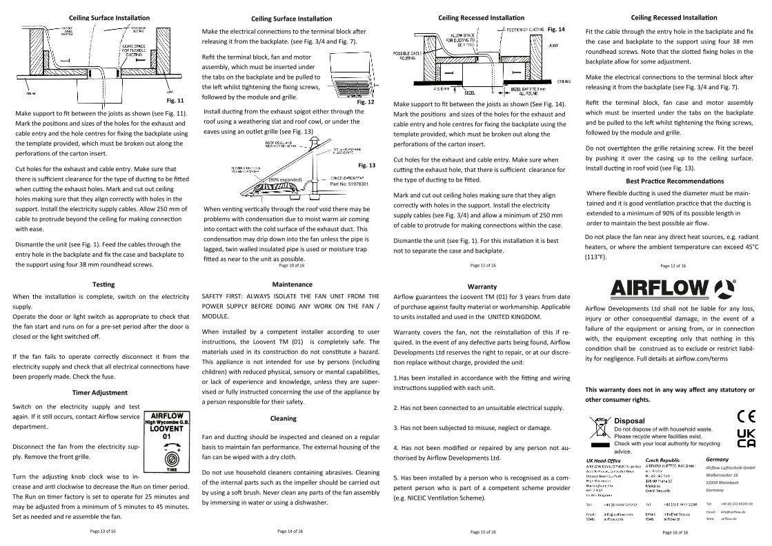
Fit the cable through the entry hole in the backplate and fix
the case and backplate to the support using four 38 mm
roundhead screws. Note that the slotted fixing holes in the
backplate allow for some adjustment.
Make the electrical connections to the terminal block after
releasing it from the backplate (see Fig. 3/4 and Fig. 7).
Refit the terminal block, fan case and motor assembly
which must be inserted under the tabs on the backplate
and be pulled to the left whilst tightening the fixing screws,
followed by the module and grille.
Do not overtighten the grille retaining screw. Fit the bezel
by pushing it over the casing up to the ceiling surface.
Install ducting in roof void (see Fig. 13).
Best Practice Recommendations
Page 11 of 16 Page 12 of 16
Page 13 of 16 Page 14 of 16 Page 15 of 16 Page 16 of 16
Ceiling Surface Installation
Where flexible ducting is used the diameter must be main-
tained and it is good ventilation practice that the ducting is
extended to a minimum of 90% of its possible length in
order to maintain the best possible air flow.
Do not place the fan near any direct heat sources, e.g. radiant
heaters, or where the ambient temperature can exceed 45°C
(113°F).
Testing
Make support to fit between the joists as shown (see Fig. 11).
Mark the positions and sizes of the holes for the exhaust and
cable entry and the hole centres for fixing the backplate using
the template provided, which must be broken out along the
perforations of the carton insert.
Cut holes for the exhaust and cable entry. Make sure that
there is sufficient clearance for the type of ducting to be fitted
when cutting the exhaust holes. Mark and cut out ceiling
holes making sure that they align correctly with holes in the
support. Install the electricity supply cables. Allow 250 mm of
cable to protrude beyond the ceiling for making connection
with ease.
Dismantle the unit (see Fig. 1). Feed the cables through the
entry hole in the backplate and fix the case and backplate to
the support using four 38 mm roundhead screws.
Ceiling Surface Installation
Make the electrical connections to the terminal block after
releasing it from the backplate. (see Fig. 3/4 and Fig. 7).
Refit the terminal block, fan and motor
assembly, which must be inserted under
the tabs on the backplate and be pulled to
the left whilst tightening the fixing screws,
followed by the module and grille.
Page 10 of 16
(90% expanded)
Ceiling Recessed Installation
Make support to fit between the joists as shown (See Fig. 14).
Mark the positions and sizes of the holes for the exhaust and
cable entry and hole centres for fixing the backplate using the
template provided, which must be broken out along the
perforations of the carton insert.
Cut holes for the exhaust and cable entry. Make sure when
cutting the exhaust hole, that there is sufficient clearance for
the type of ducting to be fitted.
Mark and cut out ceiling holes making sure that they align
correctly with holes in the support. Install the electricity
supply cables (see Fig. 3/4) and allow a minimum of 250 mm
of cable to protrude for making connections within the case.
Dismantle the unit (see Fig. 1). For this installation it is best
not to separate the case and backplate.
Part No: 51978301
Ceiling Recessed Installation
When the installation is complete, switch on the electricity
supply.
Operate the door or light switch as appropriate to check that
the fan start and runs on for a pre-set period after the door is
closed or the light switched off.
If the fan fails to operate correctly disconnect it from the
electricity supply and check that all electrical connections have
been properly made. Check the fuse.
Switch on the electricity supply and test
again. If it still occurs, contact Airflow service
department.
Disconnect the fan from the electricity sup-
ply. Remove the front grille.
Turn the adjusting knob clock wise to in-
crease and anti clockwise to decrease the Run on timer period.
The Run on timer factory is set to operate for 25 minutes and
may be adjusted from a minimum of 5 minutes to 45 minutes.
Set as needed and re assemble the fan.
Timer Adjustment
Fig. 11 Fig. 12
Fig. 13
Install ducting from the exhaust spigot either through the
roof using a weathering slat and roof cowl, or under the
eaves using an outlet grille (see Fig. 13)
When venting vertically through the roof void there may be
problems with condensation due to moist warm air coming
into contact with the cold surface of the exhaust duct. This
condensation may drip down into the fan unless the pipe is
lagged, twin walled insulated pipe is used or moisture trap
fitted as near to the unit as possible.
Fig. 14
Germany
Airflow Lufttechnik GmbH
Wolbersacker 16
53359 Rheinbach
Germany
Tel: +49 (0) 222 69205 50
Email: [email protected]
Web: airflow.de