los nlamos - federation of american scientists
TRANSCRIPT

—
LA-12189-MS
G “3 —. —--—_—— —— ——— —,
REPRODUCTIONCOPY
IS-4 REPORT SECTION
Some New Ideas for
Nuclear Explosive Spacecraft Propulsion
I
Los NlamosLosA1amosNational?-uborato~isoperatedbytheUnivmsitYofCaliforntifortheUnitedStateSDepartmentojEnergyunderconfracfW7405-ENG-36.
—

An Afj%native Action/Equal Opportunity Employer
.
This report was prepared as an account of work sponsored by an agency oftheUnited States Government. Ncn”therThe Regents of the University of Califimia, theUnited States Government nor any agency thereof, nor any of their employees, makes anywarranty, express or implied, or assumes any legal liability or responsibility forthe accuracy,completeness, or usefulness of any information, apparatus, product, or process disclosed, orrepresents that its use would notinfringeprivately owned rights. Reference herein to any specij?ccommercial product, process, or service by trade name, trademark, manufacturer, or otherwise, doesnot necessarily constitute or imply its endorsement, recommendation, or favoring by The Regentsofthe University of California, the United States Government, or any agency thereof. The viewsand opinions of authors expressed hwein do not necessarily state or reftect those ofThe Regents ofthe University ofCalifbmia, the United States Government, or any agency thereof,

— ‘r . .
LA-22289-MS
UC-940issued: October 1991
Some New Ideas for
Nuclear Explosive
Johndale C. Solem
Spacecraft Propulsion
L(M AkmmmLos Alamos National LaboratoryLos Alamos,New Mexico 87545

SOME NEW IDEAS FOR NUCLEAR EXPLOSIVE SPACECRAFT PROPULSION
by
Johndale C. Solem
ABSTRACT
Because of the deleterious effects of galactic cosmic radiation, solar flares,zero gravity, and psychological stress, there is a strong motivation to de-velop high-specific-impulse and high-thrust spacecraft for rapid transport ofastronauts bet ween the planets. I present a novel spacecraft design using alarge lightweight sail (spinnaker) driven by the pressure pulses from a seriesof nuclear explosions. The spacecraft appears to be a singularly competentand economical vehicle for high-speed interplanetary travel. Remarkably, themass of the spinnaker is theoretically independent of the size of its canopyor the number or length of its tethers. Consequently, the canopy can bemade very large to minimize radiation darnage from the nuclear explosionsand the tethers can be made very long to mitigate radiation hazard to thecrew. I calculate the specific impulse of the nuclear explosive propellant as afunction of the mass and yield of the explosives and the thrust as a functionof yield and repetition rate. I show that the weight of the sail can be greatlyreduced by tethering the canopy in many places on its surface and that thecanopy mass is directly proportional to the bomb yield and inversely pro-portional to the number of tethers. The pressure from the nuclear explosionimparts a large impulsive acceleration to the lightweight spinnaker, whichmust be translated to a small smooth acceleration of the space capsule byusing either the elasticity of the tethers or a servo winch in the space capsuleor a combination of the two. If elasticity alone is used the maximum accel-eration suffered by the space capsule is inversely proportional to the tetherlength. I address the question of thermal damage to the tethers and canopyby cursory calculation for low-yield explosives. Finally, I derive the optimumcanopy shape and show that it will generally intercept about 27r of the solidangle from the detonation point. Should the political questions connectedwith this unconventional use of nuclear explosives be favorably resolved, theinvention will be a good candidate for propulsion in the Mars mission.
. .
IntroductionThe concept of rocket propulsion using a kind of disposable reactor or external nuclearmotor* is nearly as old as the concept of a nuclear bomb. Nuclear explosive propulsionwas considered in the late 50s and early 60s under the ORIONl program at Los Alamos2and General Atomics Corporation 3. OR1ON was a heavy-lift vehicle, launched from the
* The first recorded discussion of nuclear explosive propulsion was in a Los Alamos Memo-randum by F. Reines and S. Ulam dated 1947.
1

earth or from high altitude. The nuclear explosives, which ranged in yield from a few tonsto several kilotons, were detonated behind a pusher plate fitted with shock absorbers4 tomitigate the impulsive acceleration. Nucle~ explosive schemes using a pressure vessel andconventional rocket nozzle with liquid hydrogen or water as a coolant and propellant werealso considered under the name of HELIOS5 These were abandoned as being generallyheavier and less effective than externally driven vehicles.
A baseline U.S. Air Force design had a launch mass more than 3,000 metric tons (ret) anda payload mass of about 900 mt. The craft was a behemoth, frequently referred to as aspace battleship. The pulse rate was N 0.1 to 1 s-l and the springs and dashpots weredesigned so the crew would sufer accelerations of onIy * 103 cm . S-2. The mission ofORION faded as chemical boosters became more powerful and it was realized that nuclearwarheads for ICBMS could be designed with rather modest weights.
At the dawn of the laser-fusion era, researchers believed that the use of microexplosionscould greatly reduce the weight of ORION, certainly the shock absorbers could be madeless massive or eliminated entirely. Under the unofficial title SIRIUSG, the laser-fusion in-novators designed a spacecraft with a launch mass of a mere 20 mt and a payload of nearly10 mt. They assumed, however, that the laser necessary for driving the fusion capsulcs7would weigh only 500 kg. We now realize that much bigger lasers will be required. Un-daunted by the enhanced mass requirements, imaginative scientists at Lawrence LivermoreNational Laboratory have recently designed a huge laser-fusion-powered spacecraft, whichhas been dubbed VISTAS.
We are now entering an era where manned fight to the planets is being taken seriously asevidenced by White House pronouncements on the subject. ORION may have a mission,but not the ORION of the past.
MEDUSA
For interplanetary missions, the vehicle will be assembled in space — it need not launchfrom earth as ORION did. Because there will be great concern that no radioactive debrisreaches the Earth, the spacecraft will probably be assembled and launched from one of theLagrange points. That location will place it well out of the magnetosphere and no chargedparticles will be trapped into Earth-bound trajectories.
In addition to its ill-favored environmental impact, ORION sufFered from several problemsmainly owing to its mission: (1) the pusher pIate intercepted only a small solid angIe fromthe detonation point and, even though a great deal of effort was devoted to designingasymmetrical bombs, only a fraction of the bomb-debris momentum was collected forpropulsion; (2) the pusher plate and attendant shock absorbers had to be enormously
massive and had to be carried with the spacecraft as long as it was under power; and (3)radiation damage to the vehicle as well as dose to the crew was a cent inuing problem. Inspace we have a lot of room and no gravity to deaI with, so we can replace the pusher
pla~e with a large sail or spinnaker whose canopy can intercept as large a solid angle aswe choose. The elasticity of the tethers or a
smooth out the impulsive acceleration of the
2
programmable servo winch can be used tocanopy. The tethers can be tied in many

I
places on the canopy’s surface to reduce stress on the canopy material*. As will be shown,the mass of the canopy is independent of its size and the mass of the tethers is independentof their length. The canopy can be very large and thus its fabric will be relatively immune
.
to radiation damage from the nuclear explosions. Similarly, the tethers can be made verylong, reducing shielding requirements for the crew. The concept is sketched in fig.(l).
One can visualize the motion of this spacecraft by comparing it to a jellyfish. The repeatedexplosions will cause the canopy to pulsate, ripple, and throb. The tethers will be stretchingand relaxing. The concept needed a name: its dynamics suggested MED USA.
Pressure Pulse from an Explosion in a VacuumTo get an estimate of the thrust imparted to the canopy and the specific impulse of the nu-clear explosive, we need to know the pressure impulse imparted by an atom bomb explodedin a vacuum. To make this estimate, we must find the density and velocity distributionof the sudden expansion of a sphere of gas. There is no exact analytic solution to thisproblem, but an approximate solution can be constructed on the basis of an analogousplane problem. It is given in a book by Stanyukovichg and is quoted by Zel’dovichl”,
where
r’ a;() 3–7~=$ 1–=‘=2(7–1);
R
2
r
4V Eu ——maz — ——~_lco=
~–lmb’
co is the sound speed, and E and mb are the energy and mass
= Umazt. (1)
(2)
of the bomb respectively.The solution is valid only for integer values of a and the parameter C is determined frommass conservation. For our present purposes, we can choose ~ = 5/3 and Eq. ( 1) becomes
lc%?b() 7’2/):
81TR3 l–~ “ (3)
The equation of motion for the limits t + m and R + w takes the asymptotic form
1 apg+u:=–_—.
1
R1+3(7-1) + 0’(4)
par
so the velocities of the fluid particles approach constant values and u N r/t.
ThrustSay the spinnaker canopy is at a distance r from the bomb. The mass hitting the canopyper lmit area per unit time is pu. The momentum per unit area per unit time (momentumj?uz) is pu’. The debris stagnates against the canopy, which in the frame of the debris acts
* Apparently this is not an obvious approach. That stress can be reduced in thk manner isnot generally appreciated by sail or parachute makers.
3

like a piston moving at velocity y. The piston produces a shock in the colliding debris.
The pressure behind this shockl I is
()7–1puz -’y ,
and because it is a shock, the density will increase a factor of
-y+l
Thus the impulsive pressure exerted on the canopy is
(5)
(6)
(7)
for ~ = 5/3. There will bean additional thrust imparted to the canopy by the re-expansionof the debris away from the canopy after stagnation. The largest possible impulsive pressureincluding all effects would be P = 2pu 2, but because the debris will radiatively cool during
stagnation, we will ignore the impulse from re-expa.nsion.
Then the approximate pressure applied to the canopy is
Of course, the thrust is zero until the first debris arrives at the canopy, which occurs at atime
(9)
The average thrust is simply
F = PAP, (lo)
where AP is the projected area of the canopy, and
AlP=&
IP dt,
to(11)
where At is the time between detonations.
4
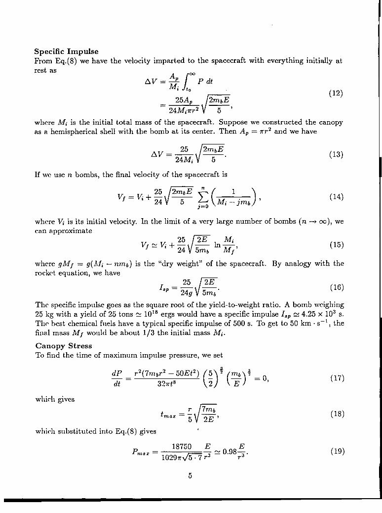
Specific ImpulseFrom Eq.(8) we have the velocity imparted to the spacecraft with everything initially atrest as
AmAV=$
/P dt
i to
r
(12)25AP 2mbE
= 24A!liTr2 5 ‘
where A4i is the initial total mass of the spacecraft. Suppose we constructed the canopyas a hemispherical shell with the bomb at its center. Then Ap = mr2 and we have
If wc use n bombs, the final velocity of the spacecraft is
V’= Vi+#/’’>(~i~jmb)
(13)
(14)
where Vi is its initial velocity. In the limit of a very large number of bombs (n + m), wecan approximate
Vf=Vi+~c
2E Mi— ln—
24 ~mb MI ‘(15)
where gh~~ = g(Afi — nmb) is the “dry weight” of the spacecraft. By analogy with therocket equation, we have
r
25 2EI.P=— —
249 5??2b.(16)
The specific impulse goes as the square root of the yield-to-weight ratio. A bomb weighing25 kg with a yield of 25 tons = 1018 ergs would have a specific impulse lSP = 4.25 x 10³ s.The best chemical fuels have a typical specific impulse of 500 s. To get to 50 km . s–l, thefinal mass Mf would be about 1/3 the initial mass Mi.
Canopy StressTo find the time of maximum impulse pressure, we set
dP
(2)’( )
r2(7Tnb~2 — 50Et2) 5 2 mfj #—=dt
— =0,327rt8 E
(17)
which gives
tF
r 7TTZb
‘a’=: 2E’(18)
which substituted into Eq. (8) gives 4
(19)
5

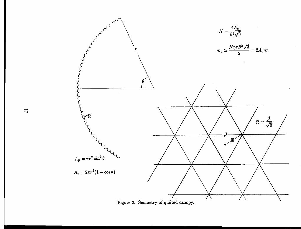
The spinnaker canopy can be tethered in many places, as shown in fig.(l). As a result ofthe pressure differential, the canopy will billow out in cup-like shapes between the tethers.For simplification, we take each of these cups to be spherical in shape. The stress in eachcup will be related to the impulse pressure by
7r!R2P = 27r!J?To, (20)
where R is the spherical radius of the cups, a is the stress in the canopy material, and ris the thickness of the canopy material. Equation (20) can be rewritten as
Pm==%
‘rein = 2cTmaz ‘(21)
. . .where Urea= 1s the stress hn-nt (tensile strength) of the canopy material and Tm i,l
.is the
minimum canopy thickness. From Eqs. ( 19) and (21) we see that for a given canopy mate-rial, the canopy mass is (1) independent of its radius, (2) directly proportionalto the bomb yield, and (3) inversely proportional to the square root of thenumb er of t et hers. The total mass of the tethers depends only on the force they musthm.r and is independent of their number.
If we fabricated the canopy in a quilt of equilateralmunber of triangles would be
4ACN=—
p’&
triangles as shown in fig.(2), the total
(22)
where /? is the edge length of the triangles and A= is the spherical area of the canopy (notcounting the dimples). The smallest radius that can be obtained is approximately thedistance from the center to the corner of the triangle, so the optimum cup radius is
PY?. z. (23)
The area of canopy material in a single cup is less than but approximately equal to 92 fi/2.The total mass of the canopy is
(24)
where q is the density of the canopy material. On average, the dimples (cups) producedby the multiple tethers increase the mass of the canopy by a factor of two over what itwould be if the canopy were smooth.
It should be emphasized that this treatment gives an extremq upper estimate of the canopystrcss. It does not account for the inertia of the canopy material and assumes infiniteresistance at the points where the tethers are tied. It is an extremely conservative estimate.
6

Spacecraft DynamicsIf we neglect the mass of the tethers, it is easy to show that ifare initially at rest and the canopy is suddenly given a velocitythe canopy is given by
—
[{
m~ pXc=vcm t+— — sin
m= k
and the position of the space capsule is given by
both canopy and capsuleAV, then the position of
where the space capsule starts at the origin, 1 is the tether length, k is the spring constantfor the tethers,
(27)
is the reduced mass and
Vcm =mcAV pAV
=m= + m~ m~
(28)
is the center-of-mass velocity. The spring constant of the tethers is given by
(29)
where At is the total cross sectional area of the tethers and Y is Young’s modulus for thetether material. The elongation of the tethers is given by
Al Xc– X~–[—=1 1
and from Eqs.(29 ) and (30), maximum elongation of the tethers is given by
Wm.=’ww%.The total mass of the tethers is mt = Atlq, so using the definition
7
(30)
(31)
(32)

in Eq. (31) we can obtain the total mass of the tethers
A?r2Ypqmt =
cl~az “
The mass of the tethers is independent of theirtheir length. The acceleration of the space capsule is
‘a=vcrntsin(tso r
i
(i=)m=z = Vcm ;.
Using Eqs.(28), (29), and (35), we can write
,.. . AV2YP
(33)
number and independent of
1 (34)
(35)
(36)
It is reasonable to make the canopy in the shape of a spherical segment at radius r out toangle O as shown in fig.(2). The canopy area is
A= = 27r7’2(1 – COS6), (37)
and the projected area isAP = m-2sin26. (38)
Following the same procedure that led to Eq.(12), we have the velocity imparted to thecanopy with everything initially at rest as
A“ =25A
‘i
2mbE
24mcxr2 5 ‘(39)
which when combined with Eqs. ( 24), (37), and (38) gives
25sin26
r
2mbEAV =
96nr2q~(l – cos 8) ~“(40)
I will show later how to optimize @ for maximum F/W, but smaller values of 6 give smallereffective I~P.
Application to the Mars MissionThe principal reason for high F/W and high I.P is to reduce exposure to GCR and solar flareradiation. Considerable uncertainty still surrounds the effects of exposures to skin, eye,and ljlood-forming organs (BFO ). NASA calculations show that a 22g . cm–3 water shield12
8

would reduce a large solar flare to 5 rem and the annual GCR to 24 rem. The minimumenergy round trip to Mars is about 18 months giving 36 rem from GCR alone. Astronautsmight accept these exposures on a one-time basis, but they are probably unacceptable whenEarth-Mars travel becomes routine. Spacecraft volumes of 100 m3 . person–l are used inNASA planning for two-month missions. A spherical four-man spacecraft would have asurface area of about 2.3 x 10²m2, and the shield weight would be about 50 mt, assumingthe NASA figures are accurate. But secondary radiation introduces a strong nonlinearityin the shielding requirement. If the tolerance levels for BFO were overestimated by as littleas 3070, the shielding requirements would be quadrupled, and more than 200 mt of waterwould be required. NASA estimates have run as”high as 1000 mt.
If the trip time is reduced by a factor of 5 to 10, the nonlinearity works so favorably asto reduce the shielding requirements to practically nothing. Part of the shield could befuel (bombs), and could be made asymmetrical to point toward the sun in case of a solarflare. A crawl space inside the fuel could be used for shelter during a solar storm. Protonsmove more slowly than light, so the astronauts could be given some warning. Furthermore,solar-flare forecasting is becoming more accurate.
Example
It is time for a numerical example. For now, I will take 6 = 7r/2 corresponding to a dimpledhemispherical shell. We can reduce the mass of the canopy indefinitely by increasing itsradius and the number of tethers. The tet hers and the canopy material become progres-sively thinner. Mylar can be fabricated to a thickness of about ~ rnil, but other practicalconsiderate ions, such as cost, will come into play long before the fabrication limit is reached.I will be conservative and say that we can spin-deploy a canopy 500 m in radius with 104tethers. For the bomb, we will again assume a yield of 25 tons & 1018 ergs in a mass of 25kg.
The best material for the canopy is probably high-strength polyethylene (aligned polyethy-lene). While it is essentially a one-dimensional material, we can easily imagine weaving itinto a two-dimensional form much as they do for bullet-proof vests. The best material thatis commercially available at this time is AUied Signal Spect~a 1000, which has a densityq = 0.97 g . cm–3, a Young’s modulus Y = 170 GPa, and a tensile strength a~.x = 3GPa. A material that has been synthesized but is not presently commercially available isSol~d-State Extruded Polyethylene, which has a density q = 0.99 g . cm–3, a Young’s mod-ulus Y = 220 GPa, and a tensile strength C~@Z = 5 GPa. Certainly materials superior tothese will be available by the time manned interplanetary flight becomes a reality.
Using r = 5 x 104 cm, we have from Eq.(19)
P18750 E
— = 7.84 x 10³dyn . cm–2“Z = lo~9~~r3
(41)
and
(42)
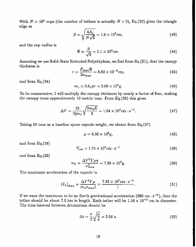
With N = 104 cups (the number of tethers is actually N + 2), Eq.(22) gives the triangleedge as
(43)
and the cup radius is@~ — = 1.1 x 103cm.!R_fi (44)
Assuming we use Solid-State Extruded Polyethylene, we find from Eq.(21), that the canopythickness is
P%mazr= = 8.62 x 10⁻⁵cm,
20(45)
maz
and from Eq.(24)mC = 2ACqn- = 2.68 x 10Gg. (46)
To be conservative, I will multiply the canopy thickness by nearly a factor of four, makingthe canopy mass approximately 10 metric tons. From Eq.(39) this gives
25
r
2mbEAv=- —~4mc
= 1.04 x 104cm. s–l.5\
Taking 50 tons as a baseline space capsule weight, we obtain from Eq.(27)
p = 8.33 X 10Gg,
and from Eq.(28)
l~.rn = 1.74 X 103cm ss-]
and from Eq.(33)AV2Ypq
mt =o~az
= 7.95 x lo5g.
(47)
(48)
(49)
(50)
The maximum acceleration of the capsule is
(i!.)maz = ;~:2y=7.33 x 107cm oS–2
1“(51)
8 maz
If we want the maximum to be an Earth gravitational acceleration (!380 cm oS–2 ), then thetether should be about 7.5 km in length. Each tether will be 1.16 x 10⁻² cm in diameter.The time interval between detonations should be
10

The Servo WinchTo make a nuclear explosive with mass 25 kg and yield 2.5 kT is not much more difficult orexpensive than to make the 25-kg, 25 T device we have used in this example. Equation (16)shows that the higher yield device would have ten times the specific impulse. The bungee-jumping approach I have shown, however, would lead to impractically long tethers. A veryattractive alternative is to use a winch. When the explosive is detonated, a motorgeneratorpowered winch will pay out line to the spinnaker at a rate programmed to provide aconstant acceleration of the space capsule. The motorgenerator will provide electricalpower during this phase of the cycle, which will be conveniently stored. After the spacecapsule has reached the same speed as the spinnaker, the motorgenerator will draw in theline, again at a rate programmed to provide a constant acceleration of the space capsule.The acceleration during the draw-in phase will be less than during the pay-out phase,which will give a net electrical energy gain. The gain will provide electrical power forancillary eqllipment in the space capsule. I have not yet worked out the details of thisapproach. I will reserve it for a future paper.
Thermal Damage to SpinnakerTethers too close to the detonation point will melt. There is a natural stay-out region thatwill affect. the overall design of the canopy. Because of the low yield, I suspect the debristemperature to be more important than radiation. We want the temperature of the debristo be less than the melting temperature of the tether material, although this limit mightbe exceeded if the debris density is small enough and the specific heat ratio is favorable.We can crudely approximate the temperature of the debris by
()‘y-l
T= ~ To,Po
(53)
where 2’0 and p. are the temperature and density of the bomb at explosion time. Againchoosing y = 5/3 and combining Eqs. (3) and (53), we have
(54)
where ti is the average particle weight (atomic, molecular, or whatever the st ate prescribes),NA = 6.02 x 10²³mole–* is the Avogadro constant, and k = 1.38 x 10–]Gerg .0 K-] is theBoltzmann constant. The maximum temperature is found by setting
dT R~ti(mbr2 – 6Et2)
x= ~5NAt5Ek (’-s)-’($=O(55)
which gives a time for maximum temperature
v’t=r ~6E ‘
11
(56)

and when substituted in
If the canopy melts at a
Eq.(54) gives a maximum temperature
temperature T~,ff, then we must have
(57)
“’”G (58)
If we take E = 1018erg, mb = 2.5 x 10⁴g, R. = 20cm, T~elf = 600”K, and ti = 25, we
ol)tain r > 18 m, which is not very restrictive. However, this crude approximation is alsorelatively sensitive to selection of ~.
Nuclear radiation damage is a long-term problem to be considered. If a hydrideused, less radiation escapes and the neutrons that do emerge are less energetic.
Optimal Canopy ShapeAs a final item, I turn to the question of the optimal “canopy shape. There is an
bomb is
intrinsic
trade-off between thrust-to-weight ratio and specific impulse, both of which are functionsof canopy angle 6 as given in fig.(2). The weight of the spacecraft is
W = (772.+ m.)9,
where m~ is the mass of tke space capsule plus the tethers, although the mass of thetethers will be a smaller component. The mass of the tethers may also be a function of 9if the capsule is not very far from the canopy. Using Eqs. ( 10), (37), and (38), we find thethrust-to-weight ratio is
F P/ipv nr2Pv sinz O
W = (2Acq~ + m,)g = [4rr2q~(l – cose) + rns]g’(59)
where ~ is the time-averaged pressure on the canopy. Following the derivation of Eq.( 16)it is easy to see that the specific impulse will be
(Go)
The spherical segment angle O~iWfor which there is maximum F/lV can be found by setting
dF/W ~~r2P1/ sin 0 27rr2qr(l – cos 0)2 – m. cos e(lo = 4xr2qr + m, – 4rr2qr COS2@ =
o, (61)9
which gives
$IJU,= arccos
[1+4~;~T-m”
(62)
In our numerical example, we chose m~/4rr2qr R 5, for which Eq. (62) gives 6f/W =1.4S7 rad = 85.2°. Chlr use of 8 = $ was pretty good.

Political ConsiderationsWe are currently prohibited by treaty from: (1) deploying weapons of mass destructionin space and (2) testing nuclear weapons in space. MEDUSA violates neither the letternor the spirit of either prohibition, but it does use nuclear explosives. The radioactivedebris from MEDUSA’s exhaust is so finely dispersed that it will be nearly undetectable.I assert that MEDUSA’S net environmental impact is less than NERVA; you have to dosomething with the spent reactor. I see no reason why nuclear explosive propulsion forinterplanetary missions cannot be made politically acceptable. Perhaps we can be morecreative and consider an international mission in which the nuclear explosives were jointlysupplied by the superpowers. What a wonderful approach to nuclear disarmament and theenhancement of science for the benefit of all humanity!
13

References
lR. Gilbert, “Advanced Technology Program Technical Development Plan,” U. S. Air Force
Systems Conm-mnd, SCLT 64-67 (1964).
2C. Everett and S. Ularn, “On a Method of Propulsion of Projectiles by Means of ExternalNuclear Explosions”, Los Alarnos Scientific Laboratory LAMS-1955 (August, 1955).
3M. Threshow, “ORION Parameter and Payload Study based on 200- and 4,000-ton Ref-erence Design,” General Atomic report GAMD-3597 (1962); J. Nance, General Atomicreport GA-5572 (1964).
4C. David aiid E. Hager, “Double-Stage Shock-Absorber Investigation,” General Atomicreport GA-5911 (1964).
‘J. Hadley, 1’. Stubbs, M. Jensen, and L. Simmons, University of California report UCRL-14238 (1965).
‘D. Bhadra, “Pulsed Nuclear Propulsion, “ Appendix D of AL-TR-89-005, “Fusion Propul-sion Study,” July 1989, by Haloulakos (McDonnell Douglas) and Bourque (General Atom-ic).
7R. Hyde, L, Wood, and J. Nuckolls, “Prospects for Rocket Propulsion with Laser-InducedFusion Microexplosions,” Lawrence Livermore Laboratory, Livermore, Calif., UCRL-74218-Rev. 2 (1972), AIAA Paper No. 72-1063 (1972); R. Hyde, “A Laser Fusion Rocket forInterplanetary Propulsion,” Lawrence Livermore National Laboratory, Livermore, Ca.lif.,UCRL-88857 (1983), Conference 34, International Astronautical Federation (1983).
*C Orth, G. Klein, J. Sercel, N. Hoffman, K. Murray, and F. Chang-Diaz, “VISTA: A.Vehicle for Interplanetary Space Transport Applications Powered by Inertial Confine-ment Fusion,” Lawrence Livermore National Laboratory, Livermore, Calif., UCRL-53802(1985); C, Orth, G. Klein, J. Sercel, N. Hoffman, K. Murray, and F. Chang-Diaz, “Trans-port Vehicle for the Manned Mars Mission Powered by Inertial Confinement Fusion,”AIAASAE/ASME/ASEE 23rd Joint Propulsion Conference, paper AIAA-87-1904 Rev. 1,Lawrence Livermore National Laboratory, Livermore, Calif., UCRL-96832 (1987); C. Orth,G. Klein, J. Sercel, N. Hoffman, K. Murray, and F. Chang-Diaz, “The VISTA Spacecraft:Advantages of ICF for Interplanetary Fusion Propulsion Applications,” IEEE 12th Sym-posium on Fusion Engineering, UCRL-96676 (1987).
14
‘K P. Stanyukovich, Unsteady Motion of Continuous Media, Pergamon Press, New York,flanslated by M. Holt, p. 501 (1960).

1°Ya. Zel’dovich and Yu. Raizer, “Physics of Shock Waves and High-Temperature Hydro-dynamic Phenomena,” Academic Press, New York, San I%ncisco, London, p. 104 (1966),
11F. Harlow and A. Amsden, Fluid Dynamics, Los Alamos Scientific Laboratory Monograph
LA-4700, p. 38 (1971).
12L. Townsend, J, Nealy, J. Wilson, L. Simonsen, “Estimates of Galactic Cosmic Ray Shield-ing Requirements During Solar Minimum,” National Aeronaut ics and Space Administra-tion, Langley Research Center, Hampton, Va, NASA TM 4167; L-16715; NAS 1.15:4167(1990), page 7, also J. Nealy, et al., “Deep Space Radiation Exposure Analysis for SolarCycle XXI from (1975-1986 ),” AEROTECH ’90 Conference (Sept/Ott 1990), SAE Paper901347.
15

1“ ,,:,ii:1.i1.“1
*
:i,1i
,:
IIII
%!9“w
\/
\
/
I/.
gQi
I
/\
/
/“\/\\
17

Thisrepofl has been reproducedduectlyfromthebestavailablecopy.
It is availabletoDOEandDOE contractors from theOffIce of Scientific attd TechnicalInformation,P.O. BOX 62,Oak Ridge, TN 37831.Prices are available from(615) 576-8401, ITS 626-8401.
It is available to the public from theNational Technical Information Service,U.S. Department of Commerce,5285 portRoyd Rd.,Springfield, VA 22161.

Los)AllmmmLos Alamos National LaboratoryLos Alamos,New Mexico 87545