low impact development in army construction · low impact development in army construction ......
TRANSCRIPT

US Army Corps of Engineers
BUILDING STRONG®
Low Impact Development
in Army Construction
Rumanda Young,
U.S. Army Corps of Engineers
Fort Worth District
Patrick Deliman,
U.S. Army Corps of Engineers
Engineer Research and Development Center
Vicksburg, Mississippi
Report Documentation Page Form ApprovedOMB No. 0704-0188
Public reporting burden for the collection of information is estimated to average 1 hour per response, including the time for reviewing instructions, searching existing data sources, gathering andmaintaining the data needed, and completing and reviewing the collection of information. Send comments regarding this burden estimate or any other aspect of this collection of information,including suggestions for reducing this burden, to Washington Headquarters Services, Directorate for Information Operations and Reports, 1215 Jefferson Davis Highway, Suite 1204, ArlingtonVA 22202-4302. Respondents should be aware that notwithstanding any other provision of law, no person shall be subject to a penalty for failing to comply with a collection of information if itdoes not display a currently valid OMB control number.
1. REPORT DATE MAY 2012 2. REPORT TYPE
3. DATES COVERED 00-00-2012 to 00-00-2012
4. TITLE AND SUBTITLE Low Impact Development in Army Construction
5a. CONTRACT NUMBER
5b. GRANT NUMBER
5c. PROGRAM ELEMENT NUMBER
6. AUTHOR(S) 5d. PROJECT NUMBER
5e. TASK NUMBER
5f. WORK UNIT NUMBER
7. PERFORMING ORGANIZATION NAME(S) AND ADDRESS(ES) U.S. Army Corps of Engineers,Fort Worth District,819 Taylor Street,Fort Worth,TX,76102
8. PERFORMING ORGANIZATIONREPORT NUMBER
9. SPONSORING/MONITORING AGENCY NAME(S) AND ADDRESS(ES) 10. SPONSOR/MONITOR’S ACRONYM(S)
11. SPONSOR/MONITOR’S REPORT NUMBER(S)
12. DISTRIBUTION/AVAILABILITY STATEMENT Approved for public release; distribution unlimited
13. SUPPLEMENTARY NOTES Presented at the NDIA Environment, Energy Security & Sustainability (E2S2) Symposium & Exhibitionheld 21-24 May 2012 in New Orleans, LA.
14. ABSTRACT
15. SUBJECT TERMS
16. SECURITY CLASSIFICATION OF: 17. LIMITATION OF ABSTRACT Same as
Report (SAR)
18. NUMBEROF PAGES
52
19a. NAME OFRESPONSIBLE PERSON
a. REPORT unclassified
b. ABSTRACT unclassified
c. THIS PAGE unclassified
Standard Form 298 (Rev. 8-98) Prescribed by ANSI Std Z39-18
US ARMY CORPS OF ENGINEERS
BUILDING STRONG
LID Definition
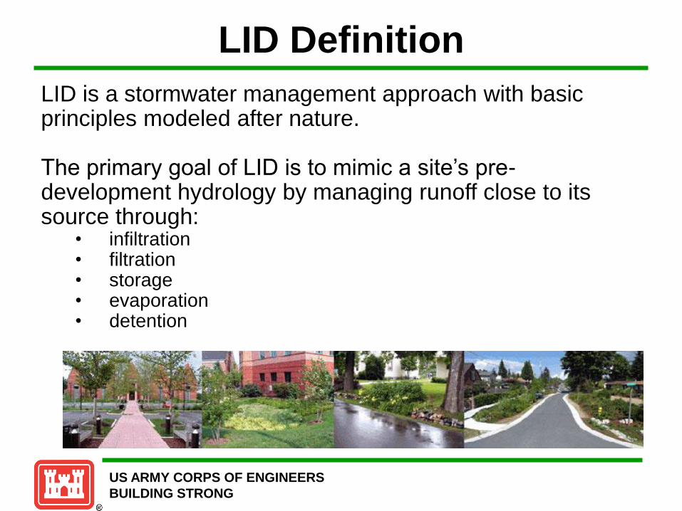
LID is a stormwater management approach with basic principles modeled after nature. The primary goal of LID is to mimic a site’s pre-development hydrology by managing runoff close to its source through:
• infiltration • filtration • storage • evaporation • detention

US ARMY CORPS OF ENGINEERS
BUILDING STRONG
LID Philosophy
Hydrology is an organizing principle that is
integrated into the initial site assessment
and planning phases.
Source: Low Impact Development Center
US ARMY CORPS OF ENGINEERS
BUILDING STRONG
LID Philosophy
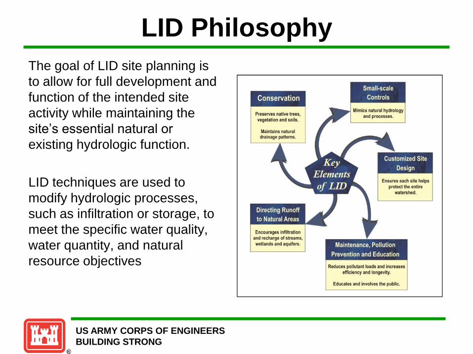
The goal of LID site planning is
to allow for full development and
function of the intended site
activity while maintaining the
site’s essential natural or
existing hydrologic function.
LID techniques are used to
modify hydrologic processes,
such as infiltration or storage, to
meet the specific water quality,
water quantity, and natural
resource objectives

US ARMY CORPS OF ENGINEERS
BUILDING STRONG
LID – Green Infrastructure • The green infrastructure movement began in the 1990’s, when
Florida, Maryland, and other states initiated programs to strategically identify, and protect connected open space systems.
• In 1999, the President’s Council on Sustainable Development identified green infrastructure as one crucial element that provides a comprehensive approach for sustainable community development.
• Green infrastructure provides several benefits, including: – Enriched habitat and biodiversity
– Maintenance of natural landscape processes
– Cleaner air and water
– Increased recreational and transportation opportunities
– Improved health
– Connection to nature and sense of place

US ARMY CORPS OF ENGINEERS
BUILDING STRONG
Conventional Conveyance
There are several issues related conventional storm water conveyance
systems, including:
• Site changes/re-grading
• Loss of recharge
• Increased water temperature
• Decreased water quality
• Higher run-off volumes
• Expensive costs
• Infrastructure repair
An important low impact development principle is the idea that storm
water is not merely a waste product to be disposed of, but rather that
rainwater is a resource.

US ARMY CORPS OF ENGINEERS
BUILDING STRONG
LID Limitations
• Site conditions may limit the
appropriateness of LID practices.
Evaluation of soil permeability, slope and
water table depth must be considered in
order to effectively use LID practices.
• Regulation limitations may necessitate the
use of structural BMPs in conjunction with
LID techniques in order to achieve
watershed objectives.
• Perception of the potential of flooding
without conventional storm sewers may limit
LID implementation.
US ARMY CORPS OF ENGINEERS
BUILDING STRONG
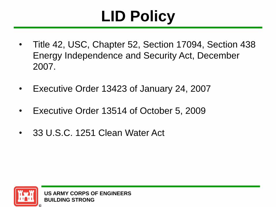
LID Policy
• Title 42, USC, Chapter 52, Section 17094, Section 438
Energy Independence and Security Act, December
2007.
• Executive Order 13423 of January 24, 2007
• Executive Order 13514 of October 5, 2009
• 33 U.S.C. 1251 Clean Water Act

US ARMY CORPS OF ENGINEERS
BUILDING STRONG
EISA Section 438
• Energy Independence and Security Act
“Storm water runoff requirements for federal
development projects. The sponsor of any
development or redevelopment project involving a
Federal facility with a footprint that exceeds 5,000
square feet shall use site planning, design,
construction, and maintenance strategies for the
property to maintain or restore, to the maximum
extent technically feasible, the predevelopment
hydrology of the property with regard to the
temperature, rate, volume, and duration of flow.”
US ARMY CORPS OF ENGINEERS
BUILDING STRONG
Executive Order 13423
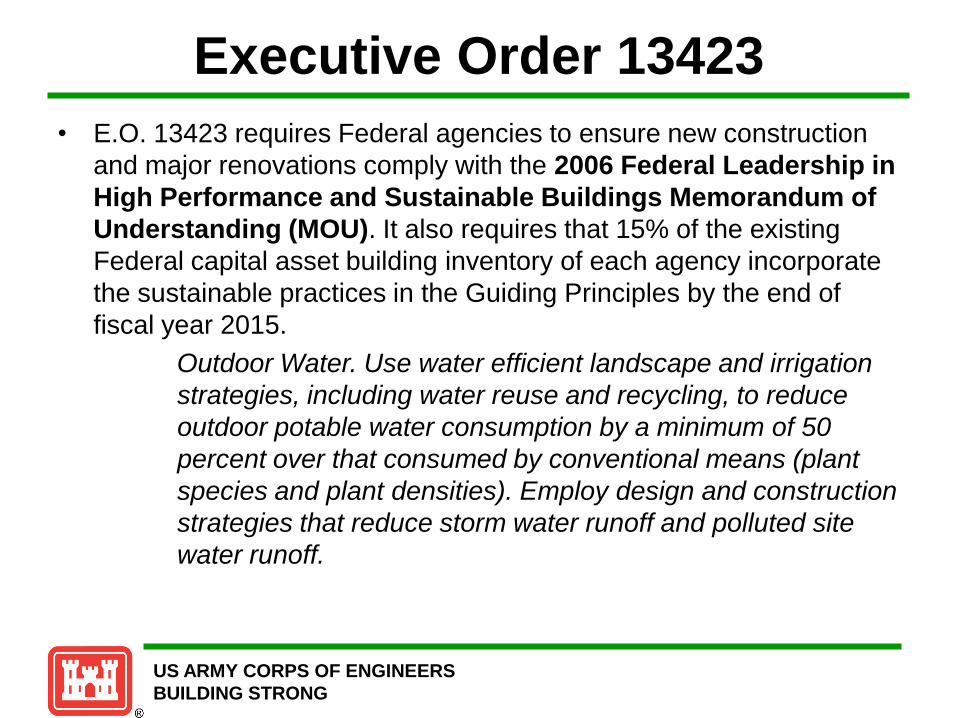
• E.O. 13423 requires Federal agencies to ensure new construction
and major renovations comply with the 2006 Federal Leadership in
High Performance and Sustainable Buildings Memorandum of
Understanding (MOU). It also requires that 15% of the existing
Federal capital asset building inventory of each agency incorporate
the sustainable practices in the Guiding Principles by the end of
fiscal year 2015.
Outdoor Water. Use water efficient landscape and irrigation
strategies, including water reuse and recycling, to reduce
outdoor potable water consumption by a minimum of 50
percent over that consumed by conventional means (plant
species and plant densities). Employ design and construction
strategies that reduce storm water runoff and polluted site
water runoff.

US ARMY CORPS OF ENGINEERS
BUILDING STRONG
Executive Order 13514
• E.O. 13514 expands the water efficiency requirements of E.O.
13423 and the Energy Independence and Security Act (EISA) of
2007. E.O. 13514 does not supersede either regulation, but does
require Federal agencies to improve water efficiency and
management by:
Reducing potable water consumption intensity 2% annually
through FY 2020, or 26% by the end of FY 2020, relative to a FY 2007
baseline.
Reducing agency industrial, landscaping, and agricultural
volumetric water consumption 2% annually, or 20% by the end of FY
2020, relative to a FY 2010 baseline.
Identifying, promoting, and implementing water reuse strategies
consistent with state law that reduce potable water consumption.

US ARMY CORPS OF ENGINEERS
BUILDING STRONG
Clean Water Act
• Restoration and
maintenance of
chemical, physical
and biological
integrity of Nation’s
waters.

US ARMY CORPS OF ENGINEERS
BUILDING STRONG
What does nonstructural mean?
The primary LID characteristic of
nonstructural BMPs is preventing stormwater
runoff from the site. This differs from the goal
of structural BMPs which is to help mitigate
stormwater-related impacts after they have
occurred.
More specifically, nonstructural BMPs take
broader planning and design approaches,
which are less “structural” in their form. Many
nonstructural BMPs apply to an entire site
and often to an entire community, such as
wetland protection through a community
wetland ordinance. They are not fixed or
specific to one location. Structural BMPs, on
the other hand, are decidedly more location
specific and explicit in their physical form. Conceptual plan using conservation design principles
Source: EPA
Nonstructural BMPs
US ARMY CORPS OF ENGINEERS
BUILDING STRONG

US ARMY CORPS OF ENGINEERS
BUILDING STRONG
The nonstructural BMPs are:
• Cluster development
• Minimize soil compaction
• Minimize total disturbed area
• Protect natural flow pathways
• Protect riparian buffers
• Protect sensitive areas
• Reduce impervious surfaces
• Stormwater disconnection.
Nonstructural BMPS
US ARMY CORPS OF ENGINEERS
BUILDING STRONG
Left and right source: Growing Greener: Putting Conservation
into Local Codes. Natural Lands Trust, Inc. 1997

US ARMY CORPS OF ENGINEERS
BUILDING STRONG
Structural BMPs
US ARMY CORPS OF ENGINEERS
BUILDING STRONG
• Bioretention (rain gardens)
• Capture reuse
• Constructed filter
• Detention basin
• Dry pond
• Wet pond
• Underground system
• Constructed wetlands
• Bioretention
• Infiltration practices
• Dry well
• Infiltration basin
• Infiltration berm
• Infiltration trenches
• Subsurface infiltration beds
• Bioretention
• Level spreaders
• Native revegetation
• Pervious pavement with infiltration
• Planter boxes
• Riparian buffer restoration
• Soil restoration
• Vegetated filter strip
• Vegetated roof
• Vegetated swale
• Water quality devices

US ARMY CORPS OF ENGINEERS
BUILDING STRONG
Structural BMP Selection
Process Development Planning:
• First Goal: prevent as
much stormwater
runoff as possible on a
site through
nonstructural planning.
• Second Goal: mitigate
stormwater runoff as
efficiently as possible
through structural
planning and design.
US ARMY CORPS OF ENGINEERS
BUILDING STRONG

US ARMY CORPS OF ENGINEERS
BUILDING STRONG
Structural BMP Selection Factors
US ARMY CORPS OF ENGINEERS
BUILDING STRONG
AestnetlcJHaDitat r-aaatao 1Ssu9S
Malnt-ananco ISSU9S
AppllcaDIIIty Dy lancl US9
RLD>1'1' quan11ty and I'U'IIOfJ
quauty nooos
Structural BMP Selection
Factors Maxlmllo dual usa
constructlon consk19ratlons
seta ractocs
costs

US ARMY CORPS OF ENGINEERS
BUILDING STRONG
LID Program Development
• OACSIM has requested USACE to provide Low
Impact Development (LID) program development
support. USACE will lead a Team of experts to
develop the Army’s LID program by completing the
following:
– LID Technical User Guide
– LID Engineering Design Standards and Construction
Specifications
– LID Training Workshops (Beginning June 2011 in Austin,
TX)
– LID Standard Operating Procedure
– LID Performance Plan
US ARMY CORPS OF ENGINEERS
BUILDING STRONG
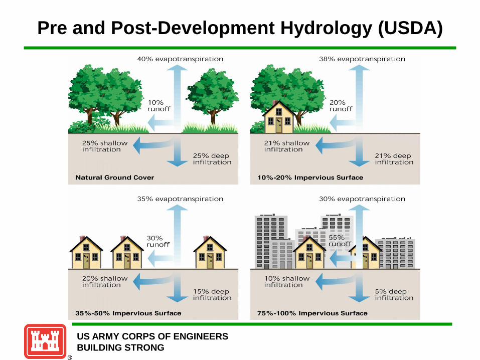
Pre and Post-Development Hydrology (USDA)
40% ev apotranspi ration
25% sh al low infiltration
Natural Ground Cover
25% deep infiltration
35% evapotranspiration
30% runoff
35%-50% Impervious Surface
15% d eep infiltration
21% shallow infi ltration
38% evapot r an spiration
2 1% deep infi llralion
10%-20% Impervious Surface
30% evapotranspiratio n
--· --· ---------------------- -..-...:. •• ••m -- --= -- ----- --m -- ----- c - 1::1
75%-100o/o Impervious Surface
--· --·-· CJ CJ CJ CJ CJ CJ CJ CJ CJ CJ CJ CJ CJ CJ CJ CJ CJ CJ CJ CJ CJ CJ CJ CJ CJ
CJ CJ
5% deep infiltration
US ARMY CORPS OF ENGINEERS
BUILDING STRONG
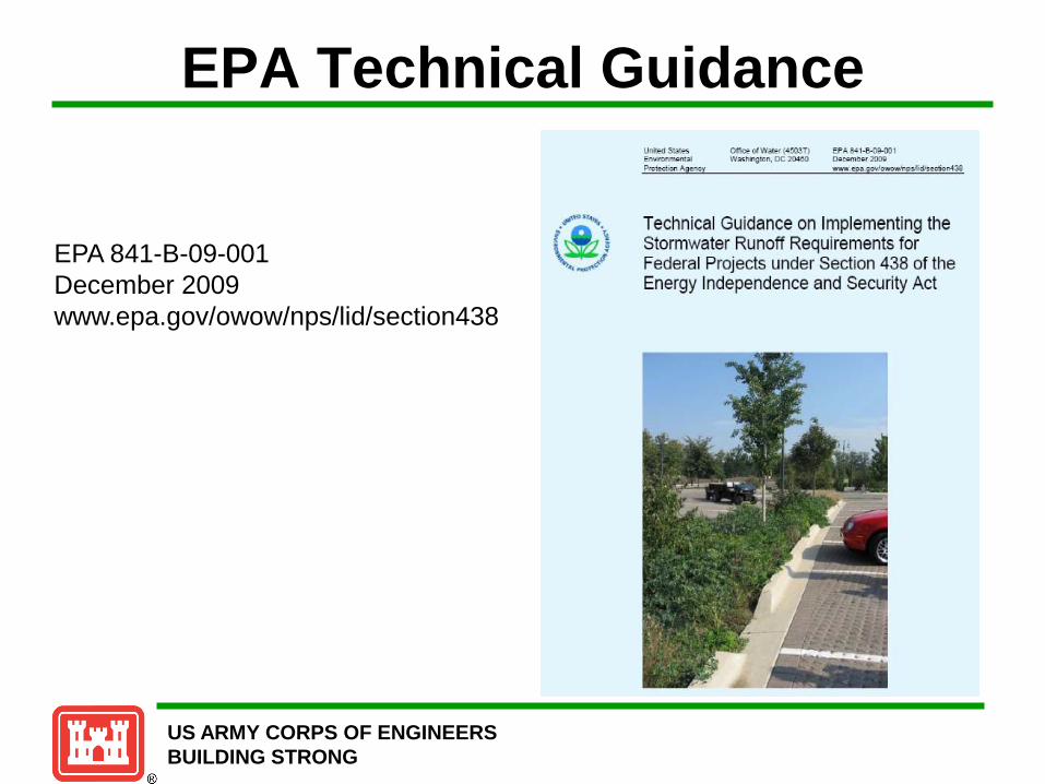
EPA Technical Guidance
EPA 841-B-09-001
December 2009
www.epa.gov/owow/nps/lid/section438

US ARMY CORPS OF ENGINEERS
BUILDING STRONG
Staying on Track
With the EPA & DOD Flowchart
EPA Technical Guidance on Implementing EISA, 841-B-09-001 December 2009
Policy Memorandum, Office of the Under Secretary of Defense, January 2010

US ARMY CORPS OF ENGINEERS
BUILDING STRONG
EISA Compliance Methodology
Maintain or Restore the Pre-development Hydrology
• Select Design Objective Option 1, Manage runoff from the 95th percentile storm event
– Determine the 95th percentile rainfall event
– Evaluate Site Conditions including: project boundary, existing vegetation, and soil types
– Calculate pre and post development runoff volumes (Apply Natural Resources Conservation Service (NRCS) Technical Report 55 (TR55) – Soil Conservation Service Curve Number Method (SCS CN))
– Manage difference between pre- and post-development runoff volumes
• Evaluate options for Low Impact Development (LID) technique designs to manage increased runoff volume.
– Consider LID features suitable for project site (LID constraints)
– Ensure selected LID design manages increased runoff volume for 24 hour period
• Accountability – Document calculations for hydrologic design (including LID employed on site)
– Waiver, if applicable
• Complete a post construction analysis of LID features
US ARMY CORPS OF ENGINEERS
BUILDING STRONG
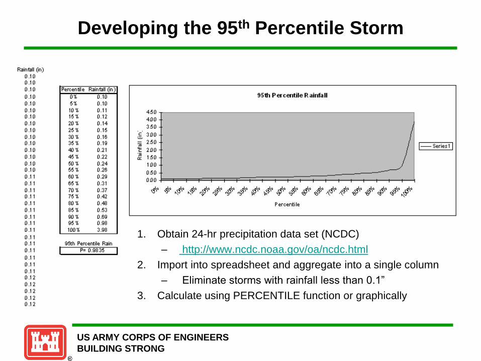
Developing the 95th Percentile Storm
1. Obtain 24-hr precipitation data set (NCDC)
– http://www.ncdc.noaa.gov/oa/ncdc.html
2. Import into spreadsheet and aggregate into a single column
– Eliminate storms with rainfall less than 0.1”
3. Calculate using PERCENTILE function or graphically

US ARMY CORPS OF ENGINEERS
BUILDING STRONG
Example 95th Percentile Storms
City 95th Percentile Event
Rainfall Total (in)
City 95th Percentile Event
Rainfall Total (in)
Atlanta, GA 1.8 Kansas City, MO 1.7
Baltimore, MD 1.6 Knoxville, TN 1.5
Boston, MA 1.5 Louisville, KY 1.5
Buffalo, NY 1.1 Minneapolis, MN 1.4
Burlington, VT 1.1 New York, NY 1.7
Charleston, WV 1.2 Salt Lake City, UT 0.8
Coeur D’Alene, ID 0.7 Phoenix, AZ 1.0
Cincinnati, OH 1.5 Portland, OR 1.0
Columbus, OH 1.3 Seattle, WA 1.6
Concord, NH 1.3 Washington, DC 1.7
Denver, CO 1.1
US ARMY CORPS OF ENGINEERS
BUILDING STRONG
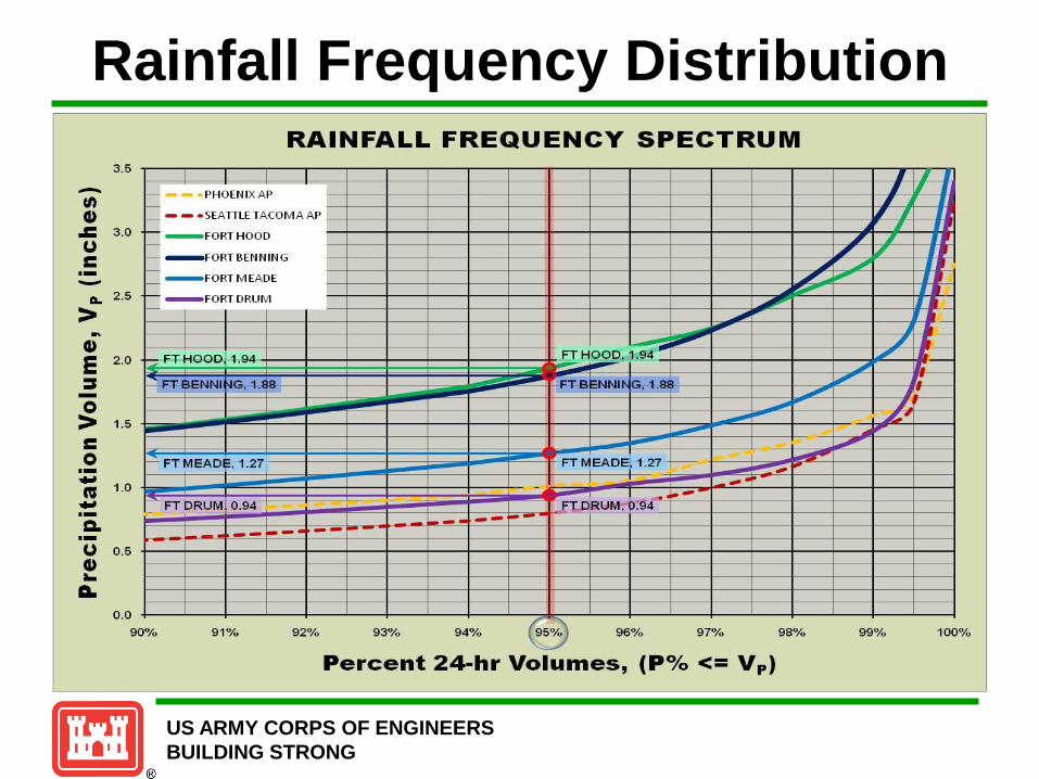
Rainfall Frequency Distribution RAINFALL FREQUENCY SPECTRUM
3 .5 -fl) Q) .c 3 .0 u c ·--
A. 2 .5
> ... Q)
E 2 .0
:I -
.-I I J I I I I - PH OEN IXAP
II I -_ -- • SEATTLE TACOM A AP I I
t-- - FORT HOOD ~ I
I I -I
- I- ·- - - r- -· 1----1---I ,
- - FORT BENN ING - I II ~
""""' J
1- - FORT MEADE I """ , I
I .... ~ • t-- - FORT DRUM __ I ~ • 1--' ''--f ~ r - -- ...... ....... j -
--1- ---1-- I -f-:; FT HOOD, 1.94 FT H~, 1 .94 ~ ,_
""""' 1-FT&ENNI IIG, 1.88 - FTBENNI" ~. 1 .88 ,
"""""""' J
0 > 1 .5
_,_ I . _,. _1- r
I""'" ---- ~ ,..
c - ~
0 ·- p FT MEADE, 1 .27 FTMEADE1
1.27 - -----.... ~ ... 1.0 ca ... ·-a. ·-
- ..... r'"'- FT DRUM . 0 .94 FT DRUM, p .94 ... ----- -- ---- --- --
u 0 .5 Q) .. a. I
0 .0 0/o 91% 92% 93% 94% 8 96% 97% 98°/o 99o/o 100 90
Percent 24-hr Volumes, (P0/o <= Vp)

US ARMY CORPS OF ENGINEERS
BUILDING STRONG
Climatology Analysis
FORT HOOD FORT BENNING FORT MEADE FORT DRUM PHOENIX AP
SEATTLE
TACOMA AP
Start Date January 1, 1950 January 1, 1959 January 1, 1950 January 1, 1950 January 1, 1950 January 1, 1950
End Date October 30, 2009 December 31, 2008 October 30, 2009 October 30, 2009 June 30, 2010 June 30, 2010
Years of Data 59.83 50.00 59.83 59.83 58.50 18.75
Total Rainfall 1541.61 2416.94 2428.85 2134.78 432.33 711.97
Average Annual Rainfall 25.77 48.34 40.59 35.68 7.39 37.97
95 Percentile Rainfall Depth 1.94 1.88 1.27 0.94 1.01 0.80
Total Rainfall >= 0.1 1505.38 2352.21 2404.30 1948.43 394.69 668.82
Total Runoff Days 2421 3646 5198 5454 1041 1756
No Runoff Days 15842 14617 16655 12809 1958 1243
Maximum Rain 3.92 5.74 3.72 3.40 2.75 3.25
US ARMY CORPS OF ENGINEERS
BUILDING STRONG
Evaluation of Site Conditions
• Determine the pre and post development project site conditions
– Evaluate existing soils (analysis) and surface features across project
site
– Determine the area (sq-ft / acres) of existing and planned: building foot
print, parking, sidewalks, etc.
– Determine the area (sq-ft / acres) of existing vegetation features and the
planned changes to the landscape
– Localized small watershed (adjoining areas for LID project
consideration)
Note: DoD definition of pre-development is
pre-project
US ARMY CORPS OF ENGINEERS
BUILDING STRONG
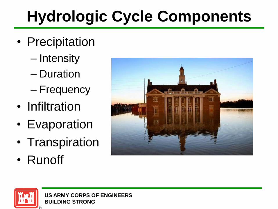
Hydrologic Cycle Components
• Precipitation
– Intensity
– Duration
– Frequency
• Infiltration
• Evaporation
• Transpiration
• Runoff

US ARMY CORPS OF ENGINEERS
BUILDING STRONG
Precipitation
• Intensity Patterns
Uniform Advanced
Intermediate Delayed Re
lati
ve
ra
infa
ll in
ten
sit
y
Time
US ARMY CORPS OF ENGINEERS
BUILDING STRONG
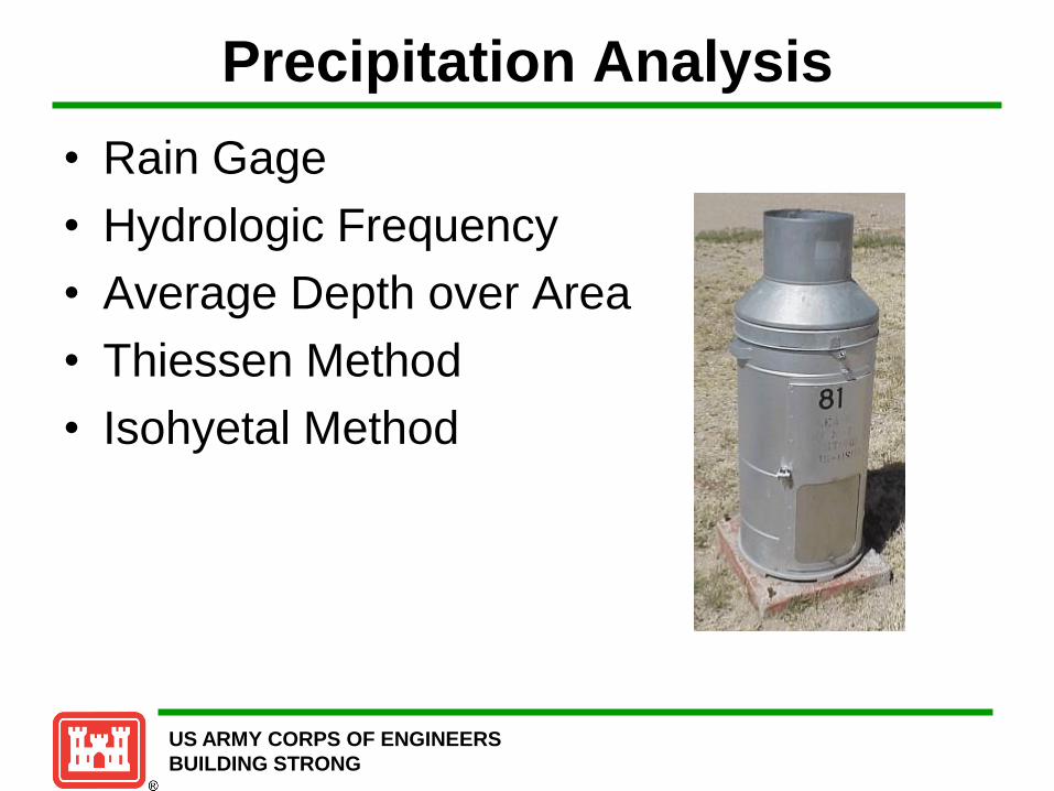
Precipitation Analysis
• Rain Gage
• Hydrologic Frequency
• Average Depth over Area
• Thiessen Method
• Isohyetal Method

US ARMY CORPS OF ENGINEERS
BUILDING STRONG
Infiltration
• Darcy’s Law
• Richards Equation
• Horton
f = fc + (f0 – fc) e-kt
f = infiltration capacity
fc = constant infiltration capacity
f0 = infiltration capacity at onset
k = positive constant for soil
t = time
US ARMY CORPS OF ENGINEERS
BUILDING STRONG
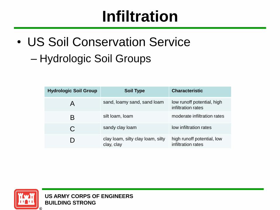
Infiltration
• US Soil Conservation Service
– Hydrologic Soil Groups
Hydrologic Soil Group Soil Type Characteristic
A sand, loamy sand, sand loam low runoff potential, high
infiltration rates
B silt loam, loam moderate infiltration rates
C sandy clay loam low infiltration rates
D clay loam, silty clay loam, silty
clay, clay
high runoff potential, low
infiltration rates

US ARMY CORPS OF ENGINEERS
BUILDING STRONG
Evaporation & Transpiration
• Evaporation from Water Surfaces
– Dalton’s Law
• Evaporation and Transpiration
– Evapotranspiration
• Blaney-Criddle
• Penman
• Empirical Solar Radiation Method
US ARMY CORPS OF ENGINEERS
BUILDING STRONG
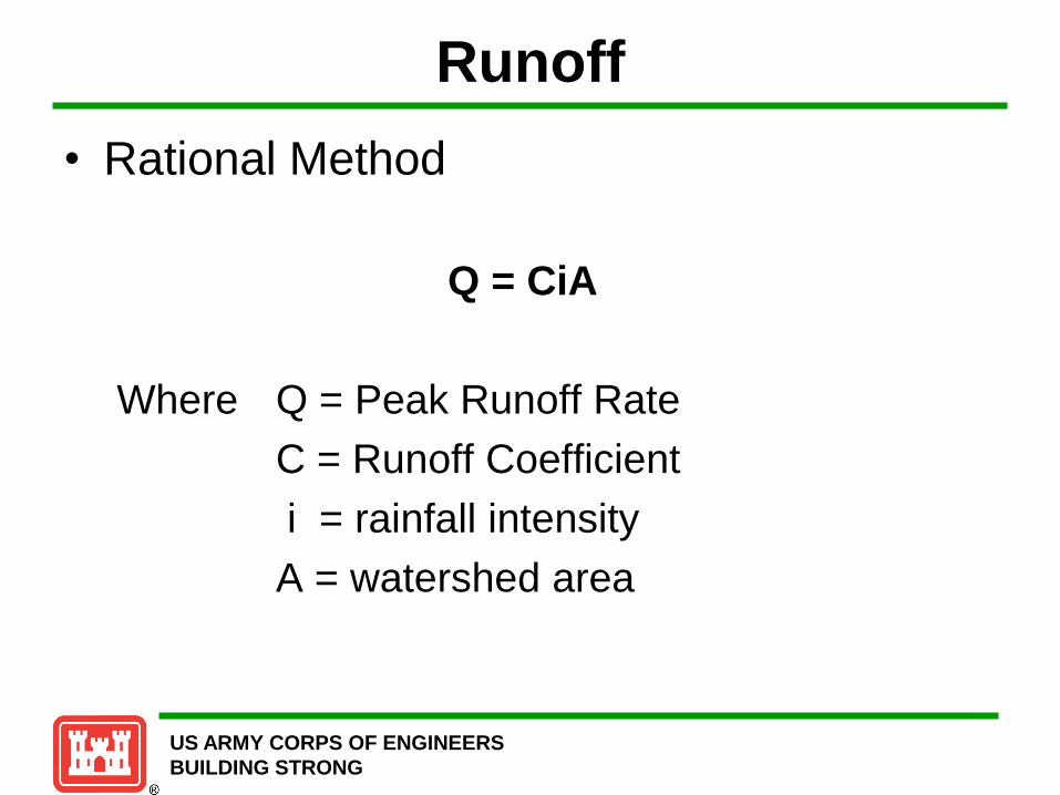
Runoff
• Rational Method
Q = CiA
Where Q = Peak Runoff Rate
C = Runoff Coefficient
i = rainfall intensity
A = watershed area

US ARMY CORPS OF ENGINEERS
BUILDING STRONG
Runoff
• Rational Method Assumptions
– Rainfall occurs at uniform intensity for
duration at least equal to the time of
concentration for the watershed.
– Rainfall occurs at a uniform intensity over the
entire area of the watershed.

US ARMY CORPS OF ENGINEERS
BUILDING STRONG
Runoff Equation
• Soil Conservation Service Method
Where: Q = direct flow volume expressed as depth
P = total rainfall

US ARMY CORPS OF ENGINEERS
BUILDING STRONG
SCS Runoff Curve Number Cune Numben for
Cover ~scription Hydrologac Sotl Group:
Average Pucent Cover T)'p'! and Hydrologic Condition Jmpen;ous Area2 A B c D
Fully dewlotHd wrl>an oreas 1~-egetotion eJtoblished)
Open spa~ (lawns. parks. golf courses, cemeteries, etc.)": Poor condttion (grus CO\'er less than so~.) 68 79 86 89 Fair condition (grus cover SO to 7S~o) 49 69 79 84 Good condition (grau cover glUter than 75~.) 39 61 74 80
lmpervtous areas: Paved parking lots, roofs, driveways. etc.
(excludina ri&ht-o!-way) 98 98 98 98 Streets and roads:
Pa,·ed: curves and storm sewers (excluding right-of-way) 98 98 98 98 Paved; open ditches (including right-of-way) 83 89 92 93 Gravel (including right-of-way) 76 85 89 91 Dirt (including right-of-way) 72 82 87 89
Western desert urban areas: Natural desert landscaping (pel" ious areas only)• 6J n 85 88 Artificial desert lan<Ucaping (impervious weed barrier, desen
shrub with I· to 2-in. sand or gravel mulch and basin borders) 96 96 96 96
Urban di$1ricts: Commercial and business 85 89 92 94 95 Industrial n 81 88 91 93
Residential districts by average lot site: i ac. or less (lown houses) 6S 77 85 90 92 ~ ac. 38 61 75 83 87 !. 3 ac. 30 57 72 81 86 + ac. 2S 54 70 80 85 I ac. 20 Sl 68 79 84 2 ac. 12 46 65 17 82
m
US ARMY CORPS OF ENGINEERS
BUILDING STRONG
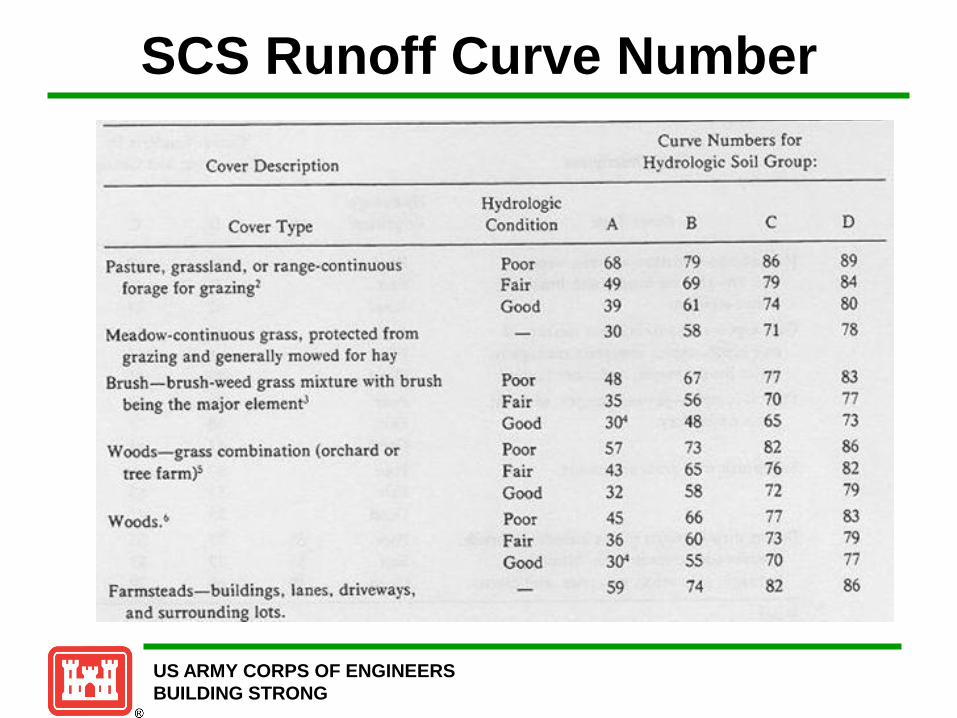
SCS Runoff Curve Number
Curve umbers ror
Cover Description Hydrologac Soil Group:
Hydrologic:
Cover Type Conduion A B c D
Pasrore, grassland, or range-continuous Poor 68 79 86 89 forage for graz;ng2 Fair 49 69 79 84
Good 39 61 74 80
Meadow-continuous grass, protected from JO 58 71 78 grazing and generally mowed for hay
Brush-brush-weed grass mixture with brush Poor 48 67 77 83 being the major elementJ Fair 35 56 70 77
Good 3()4 48 65 73
\Voods-grass combination (orchard or Poor 57 73 82 86 tree farm~ fair 43 65 i6 82
Good 32 58 72 79
Woods.~ Poor 45 66 77 83
Fair 36 60 73 79 Good 3e>- 55 70 77
Farmstead~-buildings. lanes. driveways. 59 74 82 86
and surrounding Jots.
m
US ARMY CORPS OF ENGINEERS
BUILDING STRONG
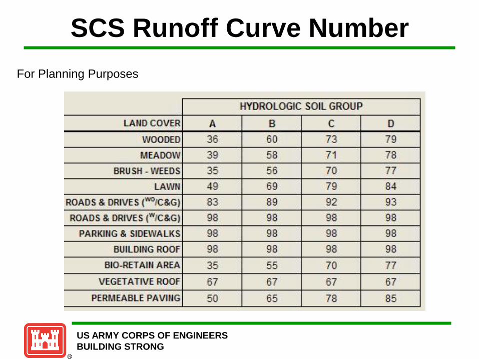
SCS Runoff Curve Number
For Planning Purposes

US ARMY CORPS OF ENGINEERS
BUILDING STRONG
Solution of Runoff Calculation
Rainfall P (em)
2.5
7 17.5
6 Runoff curve number
15.0
- 5 12.5 E c s. .._.
0 0 :t: --0 4 10.0 0 c c :;:,
:;:, ... ... ... .... v u Q) e .: 3 7.5 0 a
2 5.0
2.5
9 10 1 1 12
Rainfall P (in.)
US ARMY CORPS OF ENGINEERS
BUILDING STRONG
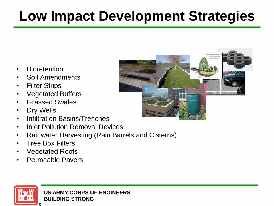
Low Impact Development Strategies
• Bioretention
• Soil Amendments
• Filter Strips
• Vegetated Buffers
• Grassed Swales
• Dry Wells
• Infiltration Basins/Trenches
• Inlet Pollution Removal Devices
• Rainwater Harvesting (Rain Barrels and Cisterns)
• Tree Box Filters
• Vegetated Roofs
• Permeable Pavers

US ARMY CORPS OF ENGINEERS
BUILDING STRONG
LID Demonstrations
Fort Hood, Texas

US ARMY CORPS OF ENGINEERS
BUILDING STRONG
Fort Hood, Texas
Fort Hood is a United
States military post
located outside of
Killeen, Texas,
Fort Hood gets 32
inches of rain per year.
The number of days
with any measurable
precipitation is 64.
On average, there are
226 sunny days per
year in Fort Hood.
The July high is around
96 degrees. The
January low is 34.
US ARMY CORPS OF ENGINEERS
BUILDING STRONG
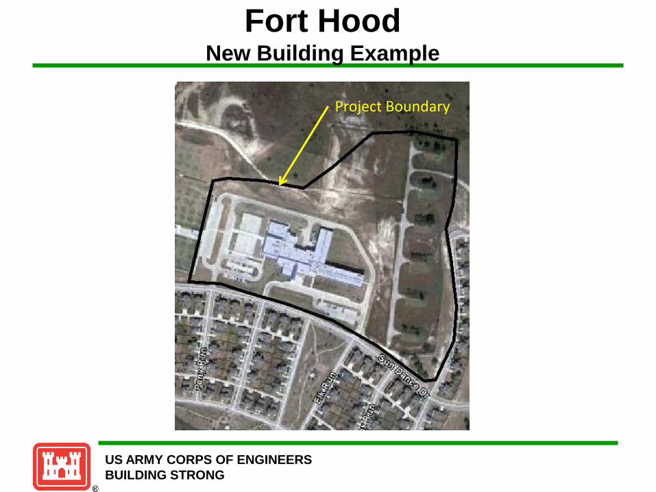
Fort Hood New Building Example
Project Boundary

US ARMY CORPS OF ENGINEERS
BUILDING STRONG
Fort Hood New Building Example
New Buildings

US ARMY CORPS OF ENGINEERS
BUILDING STRONG
Fort Hood New Building Example
·-- 4.0 .. Q .. .c A. 3.0
G)
Q
c 0 2.0 ·-.. ~ .. ·-c. ·- 1.0 u G) .. A.
0.0
RAINFALL FREQUENCY SPECTRUM FORT HOOD , TX FIFTY-NINE YEARS and TEN MONTHS of24-HOUR RAINFALL DATA (1959 - 2008)
0% 5% 10% 15% 20o/o 25% 30% 35% 40% 45% 50% 55% 60% 65o/o 70% 75o/o 80% 85% 90% 95'/~ 100%
Percent 24-hr Volumes, {P0/o <= Op)

US ARMY CORPS OF ENGINEERS
BUILDING STRONG
Hydrologic Soil Groups
Group B - Soils in this group have
moderately low runoff potential when
thoroughly wet. Water transmission through
the soil is unimpeded. Group B soils typically
have between 10 percent and 20 percent
clay and 50 percent to 90 percent sand and
have loamy sand or sandy loam textures.
Some soils having loam, silt loam, silt, or
sandy clay loam textures may be placed in
this group if they are well aggregated, of low
bulk density, or contain greater than 35
percent rock fragments.
Providing Solutions to Tomorrow’s Environmental Problems
Group C - Soils in this group have
moderately high runoff potential
when thoroughly wet. Water
transmission through the soil is
somewhat restricted. Group C
soils typically have between 20
percent and 40 percent clay and less
than 50 percent sand and have loam,
silt loam, sandy clay loam, clay loam,
and silty clay loam textures. Some
soils having clay, silty clay, or sandy
clay textures may be placed in this
group if they are well aggregated, of
low bulk density, or contain greater
than 35 percent rock fragments.

US ARMY CORPS OF ENGINEERS
BUILDING STRONG
Fort Hood New Building Example
I I I DATE: 14·Jun·11 I INSTALLATION: I Fort Hood. T@aas
~~--~~------------~~------~----------------------------------------------------~ I PLANNER: ~B_ii_IS~p_ro_u_l __ ~--------------------------------------------------------------------------~ I PROJECT NAME: New Storage Units ~OJECTLOCATION: r.F~o-rt~H~o-o~d~----------------------------------------------------------------------------~
IJECT AREA { acr@s): 23.91 95X RAINFALLj1 .94 I SELECT THE SITE'S GEN. SOIL TYPE: jsiltt-Loa~ I ~----~ ~~--~
HSG : c
I PRE PROJECT - POST PROJECT -I LAND COYER X of SITE CN LAND COYER X of SITE CN I WOODED (f•ir) WOODED (f•ir)
I "EADOW "EADOW
I BRUSH. WEEDS (f•ir) BRUSH. WEEDS (hir)
: LAWM 58.0:X 79 LAWM 52.8:X 79 I ROADS • DRI9ES ("•IC.6) 22.0:X 92 ROADS • DRI'fES ("•IC.6) 22.2:X 92 I ROADS • DRIUS (" IC.6) ROADS • DRIUS (" IC.6)
I PARICI"6· DRIUWATS • SIDEWALKS PARKI"6· DRIUWATS • SIDEWALKS
I BUILDIM6 ROOF 20.0:X 98 BUILDI"6 ROOF 25.0:X 98
I I SELECTION OF
OTHER LAND COYER TYPES
TOTAL x 100.0% TOTAL x 100.0% VEIGHTED AVERAGE CNn = 85.7 VEIGHTED AVERAGE C~ld = 86.6
.-----R_U_~I.....,.O=F_,F ..,VOLUME (95% RAUl) =I 1.670 I ACRE-FE~
.__ _____ 72_7_5__.51 CUBIC FE~._ _____ 544_ 2_06__.. GALLON~
MINIMUM RUtmFF RETEtmOt~ VOlUME TO COMPlY WJ!H EISA 438 VOlUME COtiTROl REQUIREMEtiT
0.105 ACRE-FEET 4,587 CUBIC FEET 34,308 : I I
GALLON~
!
US ARMY CORPS OF ENGINEERS
BUILDING STRONG
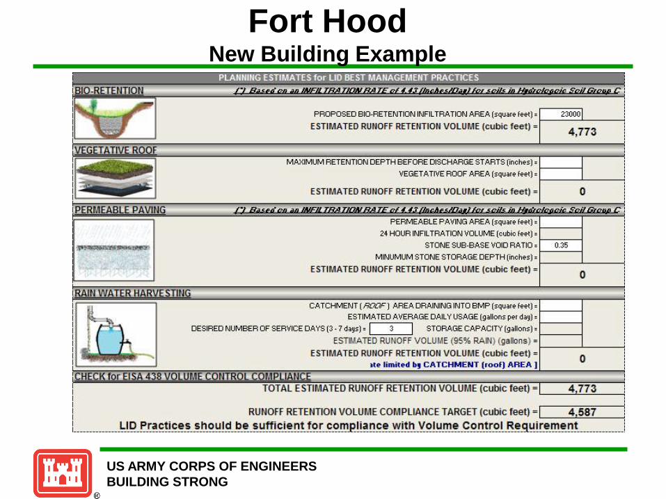
Fort Hood New Building Example
PROPOSED BID-RETENTION INFILTRATION AREA (squarE? fE?E?t) = 1-----'------4
ESTIMATED RUNOFF RETEUTION VOLUME (cubic feet)= 4,773
MAXIMUM RETENTION DEPTH BEFORE DISCHARGE STARTS (inches)= 1------l
VEGETATIVE ROOF AREA (square feet)= 1-----'------i
ESTIMATED RUNOFF RETHITION VOLUME (cubic feet) = 0
PERMEABLE PAVING AREA (square feet)= 1------i
24 HOUR INFILTRATION VOLUME (cubic feet)= 1------i
STONE SUB-BASE VOID RATIO= 1------l
MINUMUM STONE STORAGE DEPTH (inches)= 1-----'-----1
ESTIMATED RUNOFF RETHITION VOLUME (cubic feet)= 0
CATCHMENT(~) AREA DRAINING INTO BMP (square feet)= 1------i
ESTIMATED AVERAGE DAILY USAGE (gallons per day) = DESIRED NUMBER OF SERVICE DAYS (3- 7 days)= I 3 I STORAGE CAPACITY (gallons)= 1------i
ESTII.1ATED RUNOFF VOLUI.1E (95% RAIN) (gallons) = 1-----'-------!
ESTIMATED RUNOFF RETEtiTION VOLUME (cubic feet)= ue l imi ted bt CA TCHMENT (roo f) AREA ]
0

US ARMY CORPS OF ENGINEERS
BUILDING STRONG
Fort Hood New Building Example
Rain Gardens

US ARMY CORPS OF ENGINEERS
BUILDING STRONG
Summary
• Implementation of Section 438 of the EISA can be
achieved by incorporation of GI/LID
• EPA 841-B-09-001 provides technical guidance on
implementing the stormwater runoff requirements
• The TR55 model is available to support stormwater
modeling analysis efforts
• Potential LID features can be evaluated prior to
implementation
• Defensible and consistent hydrologic assessment tools
should be used and documented

US ARMY CORPS OF ENGINEERS
BUILDING STRONG
Questions