low power pulsed mpd thruster system analysis and applications · nasa contractor report 191187...
TRANSCRIPT

NASA Contractor Report 191187
AIAA-93-2391
Low Power Pulsed MPD Thruster
System Analysis and Applications
Roger M. Myers
Sverdrup Technology, Inc.
Lewis Research Center Group
Brook Park, Ohio
Matthew Domonkos
University of New Mexico
Albuquerque, New Mexico
and
James H. Gilland
Sverdrup Technology, Inc.
Lewis Research Center Group
Brook Park, Ohio
Prepared for the
1993 Joint Propulsion Conference
cosponsored by the AIAA, SAE, ASME, and ASEE
Monterey, California, June 28-July 1, 1993
(NASA-CR-191187) LOW POWER PULSED
MPD THRUSTER SYSTEM ANALYSIS AND
APPLICATIONS (Sverdrup Techno|ogy)28 D
N94-13415
Unclas
G]/20 0186028
https://ntrs.nasa.gov/search.jsp?R=19940008942 2018-07-17T01:08:18+00:00Z


Low Power Pulsed MPD Thruster System
Analysis and Applications
Roger M. Myerst
SverdrupTechnology,Inc.NASA Lewis ResearchCenter
Cleveland,OH 44135
Matthew Domonkos 2
University of New Mexico
Albuquerque, NM
and
James H. Gilland3
Sverdrup Technology, Inc.NASA Lewis Research Center
Cleveland, OH 44135
Abstract
Pulsed MPD thruster systems were analyzed for application to solar-electric orbit transfer vehicles at power
levels ranging from 10 to 40 kW. Potential system level benefits of pulsed propulsion technology include ease of
power scaling without thruster performance changes, improved transportability from low power flight experiments to
operational systems, and reduced ground qualification costs. Required pulsed propulsion system components include
a pulsed applied-field MPD thruster, a pulse-forming network, a charge Control unit, a cathode heater supply, and
high speed valves. Mass estimates were obtained for each propulsion subsystem and spacecraft component usingoff-the-shelf technology whenever possible. Results indicate that for payloads of 1000 and 2000 kg pulsed MPD
thrusters can reduce launch mass by between 1000 and 2500 kg over those achievable with hydrogen arcjets, whichcan be used to reduce launch vehicle class and the associated launch cost. While the achievable mass savings depends
on the trip time allowed for the mission, cases are shown in which the launch vehicle required for a mission isdecreased flom an Atlas IIAS to an Atlas I or Delta 7920.
C
Cs
go
Isp
It
Ls
Ill
1%
Nomenclature
capacitance of pulse-forming network, F
capacitance per stage of pulse-forming network, F
energy per pulse, J
acceleration of gravity, 9.8 m/s 2
specific impulse, s
mission total impulse, N-s
inductance per stage of pulse-forming network
propellant mass flow rate, kg/s, defined by Eqn. (6)
mass of capacitors in PFN, kg
1 Propulsion Engineer, member AIAA
2Undergraduate student, member AIAA
3Research Engineer, member AIAA
This paper is a work of the U.S. Government and is
not subject to copyright protection in the United States.

Mf
Mpay
Mp.c.
Mp.s.
Mpow
Ms_
NpN,
Nt
PpPt
Tf
vpAV
7-o
CCc
_3t
"Cp
final spacecraft mass, kg
payload mass, kg
propellant management system mass, kg
propulsion system mass, kg
power system mass, kg
structural mass, kg
total number of pulses required per thruster
number of stages in pulse-forming network
number of thrusters
peak power during pulse, W
thruster power, W
tankagefraction
thrustervoltageduringpulse,V
mission velocity increment, m/s
thruster discharge impedance, ohms
capacitor specific mass, kg/F
thruster efficiency
pulse duration, s
Introduction
Magnetoplasmadymmic (MPD) thrusters have dernonstmted performance and power handing capabilities whichmake them attractive for use on orbit transfer and planetary missions. 1-3 Testing has been done at power ranges
from 10 kW to 600 kW on steady-state thrusters, and from 200 kW to 10 MW with pulsed thrusters with single
pulse durations up to 10 ms. The simple and robust MPD thruster design permits operation at power densities
exceeding those of other electric propulsion technologies. While most MPD thruster testing has been directed at
applications requiring hundreds of kilowatts of power for propulsion, recent efforts have focussed on the potential
for near-term application of MPD thruster technology at power levels below 40 kW, where previous studies haveindicated that steady-state thrusters have poor performance characteristics for all propellants except lithium. 1,2,4 Use
of lithium may be precluded because of potential spacecraft contamination from the condensable propellant. These
performance and integration limitations have led to the consideration of pulsed propulsion systems, in which the
thrusters operate at constant peak power with a duty cycle dictated by the available spacecraft power.
Two experimental pulsed MPD thruster systems have been flown in space. The trust of these, 5 flown on the
MS-T4 spacecraft in 1981, consisted of two applied-field MPD thrusters operating on ammonia propellant. The
results indicated that ground performance measurements were correct, and that the 1.5 ms duration, 100 kW peak
power discharges did not interfere with other spacecraft functions. The MS-T4 propulsion system power was 30 W,
and the thrusters discharged about once every 32 seconds for a total of 400 discharges. The second flight
demonstration, on the fast Space Experiments with Particle Accelerators (SEPAC) Space Shuttle flight in 1985, 6-s
utilized a much higher peak power discharge of 2 MW, and showed that very high power pulsed systems could be
successfully integrated and flown on manned spacecraft. Neither of these flights utilized thrusters or systems with
the performance and lifetime required for operational systems, but they were an important step in demonstrating the
feasibility of integrating pulsed MPD thruster technology. Additionally, pulsed thrusters with up to 3 MW peak
power and discharge durations of ,10 gsec are being flown on the Navy NOVA spacecraft, and have demonstrated
over 10 years of on-orbit lifetime.9, I0 A large amount of work has been done to integrate pulsed electromagnetic
propulsion on spacecraft, and no insurmountable issues have been discovered. 9 The flight of the Japanese Electric
Propulsion Experiment (EPEX) on the Space Flyer Unit, scheduled for launch in 1994, will demonstrate a pulsed

MPDthrustersystemona1kWspacecraft.Thethrusterwill use hydrazine propellant, and the peak pulse power is
over 2 MW. The principal issue with this system appears to be the short pulse duration of 150 Its, which reduces
the fraction of injected propellant actually accelerated to below 50% and dramatically reduces the thruster
performanceP The EPEX propulsion system has passed both EMI and vibration qualification testing.t I
There are several potential advantages of pulsed MPD thruster systems, including power scaling without changes
in thruster performance or size and reduced testing costs. Power scaling is accomplished via changes in pulse
frequency, with no modification to the thruster or its operating conditions during a pulse. This means that thruster
efficiency and specific impulse are unchanged as the power level changes, and that power restrictions resulting from
either solar array degradation or increased distance from the sun will not impact thruster performance. This capability
improves the transportability of data obtained on low-power flight tests to full-scale operational systems. The
additional complexity of having an energy storage unit and high-speed valves may be offset by the ability of one or
two thrusters to process all the power available for propulsion, reducing the need for a large number of thrusters.
Finally, pulsed MPD thrusters will likely have reduced testing costs, since accurate performance measurements and
integration tests can be made on a single or multiple pulse basis with pressures near the ultimate facility pressure,with long-term lifetime and thermal characterizations made at the higher facility pressures associated with continuous
operation. MPD thrusters have been shown to be insensitive to facility pressure for values below 0.07 Pa, a valuewhich is readily achievable in available large space simulation facilities for the time average propellant flow rates
expected at power levels below 100 kW.l
Potential near term applications of pulsed MPD thruster systems include primary propulsion for solar electric
orbit transfer vehicles (SEOTVs) and planetary spacecraft which have an electric power capability of 10 to 40 kW.
The goal of this study is to establish the power level and mass regimes for which pulsed MPD thrusters are
competitive with hydrogen arcjets and to identify key technology requirements. Hydrogen arcjets were selected for
comparison because of the similarity of the thruster propellants. A comparison with ion thrusters was beyond the
scope of this work. Previous studies have been performed which examined the application of pulsed thrusters to 100kW class nuclear electric propulsion systems. These efforts generally found that, given the technology available in
the early 1980's, the mass of the energy storage system was such that pulsed MPD thrusters were ineffective at
power levels much below 100 kW. 12,13 In addition, cathode erosion in pulsed thrusters was found to be too highto achieve the long thruster lifetimes required. 14 Since that time, however, considerable effort has gone toward the
development of improved capacitors for pulsed power applications, and a new examination of the cathode lifetime has
resulted in a potential solution to the lifetime limitations.
This paper presents an analysis of pulsed MPD thruster systems including recent technology developments. The
components of a pulsed MPD thruster system are described first, including the thruster, power management, thermalcontrol, and propellant storage and distribution systems. Mass estimates are developed for each component valid for
power levels between 10 kW and 40 kW. Spacecraft integration issues are then discussed in the context of previous
flight experience. The results of the mass analysis are used in a simple mission model to establish benefits for
pulsed MPD thrusters by comparing them with hydrogen arcjets. The sensitivity of the initial spacecraft wet-massto thruster and power processor performance are examined. Finally, a summary of the major conclusions of this
study is provided.
System Components
Pulsed propulsion technologies will only be used if they offer sufficient mission and development cost benefitsto offset the added complexity of the high-speed valves and energy storage system. While continuous propellant feed
systems have been proposed to eliminate the high speed valve, 15 this technique is not considered in this study due to
the high repetition rates (-104 Hz) required to maintain high propellant utilization efficiency. The propellantutilization efficiency in continuous feed systems also couples the thruster length, performance, pulse power, and
spacecraft power, which compromises the ability of pulsed systems to accommodate spacecraft power changes

without simultaneous changes in thruster performance. A simple schematic of the pulsed propulsion system
considered in this work is given in Fig. 1, where the charge control unit, CCU, serves as the interface between the
spacecraft bus and the pulse forming network, and the cathode heater supply maintains a sufficiently high cathode
temperature to ensure thermionic emission. For all pulsed systems, the mass of the energy storage unit isdetermined by its specific energy and the energy per pulse, where the latter is determined by the total mission energy
change and the total number of pulses. Thus, the relative merits of pulsed and steady-state systems will bedetermined by the mission requirements, the performance of the different thrusters, and the system masses. While it
is premature to specify a thruster or system design, this section describes the component design criteria and presents
a point design which is used as a basis for comparisons with hydrogen arcjets.
Thruster
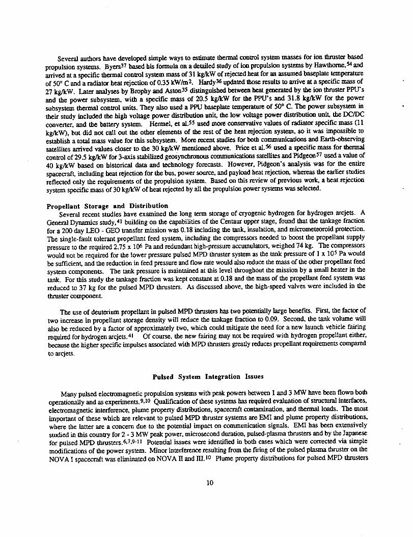
The thruster includes the electrodes, applied-field magnet, insulators, propellant injection system, and any heat
rejection hardware required by these elements. The highest pulsed MPD thruster performance measured to date has
been obtained at Princeton University using a self-field thrusterl6 and at Osaka University using an applied-field
thruster. 17 Both thrusters used hydrogen propellant, and their efficiency exceeded approximately 50% at 7000 s Isp.
While this Isp is too high for optimal LEO-GEO transfer times, there are several options currently being explored
to reduce the Isp while maintaining the efficiency. These include the use of deuterium or lithium propellants,
geometry changes, and optimizing the shape and strength of the applied magnetic fields. Deuterium has been used intests at the Los Alamos National Laboratory, and simple performance estimates indicate efficiencies near 50% at
5000 seconds Isp.18 Lithium, while not yet tested in pulsed thrusters, has yielded performance levels over 60%
efficiency at 5000 s Isp at a power level of 20 kW. 9 Work in Japan and the United States has shown that thruster
performance can be significantly improved via changes in thruster geometry, including flaring the anode, shorteningthe cathode, and modifying the propellant injection. 1,2 Applied magnetic fields have been extensively studied in the
United States, Japan, and the former Soviet Union, and have been found to increase thruster performance for bothsteady-state thrusters at power levels up to 200 kW and pulsed thrusters at peak power levels of several megawatts.9
However, the complex physics governing operation of applied-field MPD thrusters has to date precluded thruster
optimization. Only recently have the experimental data base and numerical codes approached the level required to
permit reasoned approaches to applied-field MPD thruster design.l,9,19
For this study the thruster geometry was based on the Princeton thrusterl4,16 with modifications made both to
accommodate an applied magnetic field and to achieve the required lifetime. The Princeton benchmark thruster has ananode radius of 5 cm, a cathode radius of 0.9 cm, and a chamber length of 10 cm. The electrode geometry was
modified to accommodate the 2500 - 6000 hour lifetime required for the LEO - GEO transfer missions. The
principal life-limiter in these thrusters is the cathode, principally as a result of operation at current densities beyond
the material capability or at too low a surface temperature.14 Cathodes operated properly have demonstrated lifetimesover 12,000 has at current densities of 20 - 30 AJcm2 under vacuum conditions.2O,21 These results were obtained
using porous tungsten impregnated with a 4:1:1 molar mixture of BaO, CaO, and A1203 operated at 1050 "C. A
peak discharge current of 7.5 kA was selected for this study, yielding a required emitting surface area of 375 cm2 foran emission current density of 20 A/cm2. Assuming that the cathode surface can be textured or grooved so as to
increase the emitting surface area by a factor of two and that the uniform surface temperature results in uniform arcattachment, the cathode radius and length should be 1.6 cm and 17 cm, respectively. The cathode wall thickness
was arbitrarily set to 0.64 cm. The anode geometry was chosen to be a straight cylinder 6.5 cm in radius and 17 cm
long, though use of a flared anode such as those used in several Japanese studies would not strongly affect the
results. Although it is likely that a lighter weight, higher conductivity material could be used, molybdenum wasselected as the anode material because it would yield a conservative weight estimate. The anode wall thickness was
set to 0.3 cm. These thruster components are illustrated in Fig. 2.
The surface temperature of barium impregnated tungsten cathodes must be maintained at a uniform temperature
of about 1050 "C to ensure adequate thermionic emission.20 This will be accomplished by imbedding a heater inside
the cathode. Several heater designs have demonstrated operation at over 1100 "C for several thousand hours, including

heaters currently used on flight qualified resistojets and heaters that have flown on ion thrusters. Resistojet heaters
designed to survive exposure to oxidizing propellants have been tested at temperatures over 1000 "C for 10,000
hrs.22 The heater power requirement for this study was estimated from the sum of the radiated and conducted power
away from the cathode. The radiated power was calculated assuming that the anode temperature was equal to the
cathode temperature, a condition which will be shown to be reasonable, and that the backplate surface temperaturewas 300 "C cooler than the cathode. The appropriate view factors were calculated, and it was found that the cathode
radiated between 240 and 470 W, depending on the impact of the surface texturing on the effective radiating area.
Heat conduction was estimated to be between 150 and 200 W depending on the required wall thickness of the cathode
base, yielding a total heater power requirement of between 390 and 670 W. The performance loss resulting fromohmic dissipation in the thin walls of the cathode base was found to be negligible, though the structural
implications were not examined.
The anode and radiator size were determined from the requirement that all power deposited into the anode be
radiated at the anode temperature. For peak power levels between 1.5 - 2.5 MW the fraction of input power
deposited into the anode was between 25 and 35 percent with argon propellant. 23 Propellant and applied-field effects
studies for both pulsed and steady-state thrusters 24,25 have shown that the anode power fraction is lower with
hydrogen propellant than with argon and that it decreases with increasing applied-field strength and input power.
The lowest reported value is 21% at a pulsed input power of 1.1 MW.25 For this study the anode power fraction was
assumed to be 30 percent. Using a wall thickness of 0.25 cm and an emissivity of 0.8 the anode was found to be
capable of radiating all of the absorbed power for average power levels of 40 kW or below without the need for anadditional radiator. At the maximum average power of 40 kW the anode surface temperature was 1045 °C, which
confu'ms that the anode and cathode temperatures can be near equal. The anode temperature could be reduced by
extending a radiator fin off the front of the anode if necessary. Anode life has been found to be limited by sputtering
for high molecular weight propellants such as argon and by localized melting when the thruster is operated at too
high a current level.26 Minimal sputtering should occur when using hydrogen, deuterium, or lithium propellantswith refractory metal anodes.26 Localized melting can be avoided by operating at lower peak current levels and by
manufacturing the anode out of a high thermal conductivity material. The latter solution was found to be very
effective in teflon propellant pulsed plasma thrusters at peak power levels over 3 MW, in which the lowest anode
erosion rate was measured with a copper anode.27
The substantial benefits observed with applied magnetic fields led to their inclusion in this study. Pulsed
applied-field thrusters with the solenoid connected in series with the thruster discharge have been tested in
Japan,2,17,25,28,29 and the principal thruster modification required was to ensure that the applied magnetic field candiffuse through the anode in a time short compared to the discharge time. This has been successfully accomplished
for one millisecond discharges by cutting the anode axially and using thin walled anodes,17, 25,28,29 and thus should
not be a problem for the longer discharge times considered in this work. For this study the design of the applied-field coil was dictated by the desired field strength and the thruster discharge current. Previous studies using applied-
field strengths of up to 0.2 T with steady-state thrusters show that the performance improves monotonically with
field strength. Based on these results, a value of 0.2 T was selected for this study, and the coil radius was chosen
such that a gap of 4 cm was left between the thruster anode and the coil. This gap can be used for radiation shieldswhich will be needed to limit radiative heat transfer from the anode to the magnet. A preliminary estimate of the
number of turns required in the applied-field coil was obtained using a model which an infinitely long solenoid. The
result was then used in a finite length solenoid code developed by LaPointe 3° to establish accurate coil requirements.
The coil was designed to be self-cooling by using flat copper stock to increase its surface area. The coil temperature
was found by equating the average ohmic power deposition into the coil with the radiative heat loss. For the selectedcurrent level of 7.5 kA and a spacecraft power level of 40 kW, it was found that 5 turns of 2 cm wide, 0.5 cm thick
copper would provide the required magnetic field and would self-cool at a temperature below 100 "C if coated to
achieve an emissivity of 0.8. It is clear from this result that pulsed applied-field MPD thrusters will not require the
development of new materials for the external solenoid.
A major difficulty with pulsed propulsion systems has been the achievement of high propellant utilization

efficiency.31 Propellant utilization efficiency is defined as the fraction of the total propellant injected per pulse
which participates in the discharge. Achievement of high propellant efficiency has required _ development of fast,
extremely reliable valves and careful design of the propellant feed system to minimize the "dead volume" between the
valve and the thruster. The controlling variables for propellant efficiency are the required pulse shape, trapped
volume size, the pressure in the trapped volume, the pulse duration, and the propellant type. Only square propellant
pulses were considered in this work. In this case, the trapped volume size and pressure should be minimized, the
pulse duration maximized, and the propellant should be a low molecular weight gas. These rules lead to a reduction
of the propellant mass which is not accelerate& The lower limit on the trapped volume pressure is determined by the
requirement that the injection orifices be choked, and it can be varied by changing the mass flow rate and the total
injection orifice area. Jones31 showed that a square propellant pulse is best achieved using a large valve orifice, asmall total thruster orifice area, and a small trapped volume. The ratio of the valve orifice area to the thruster orifice
area should be less than 0.5. In addition, increasing the thruster injection plenum temperature improves the gas
efficiency by reducing the density of the gas in the trapped volume.
For this study the propellant injection geometry was designed to be similar to that used in the Japanese
thrusters17,25,28,29 in which all propellant is injected around the cathode base, though scaled to accommodate the
larger cathode diameter needed to ensure adequate lifetime. The result is shown in Fig. 2, where the wapped volumeconsists of the tube joining the high-speed valve to the annulus around the cathode base. The tube and annulus
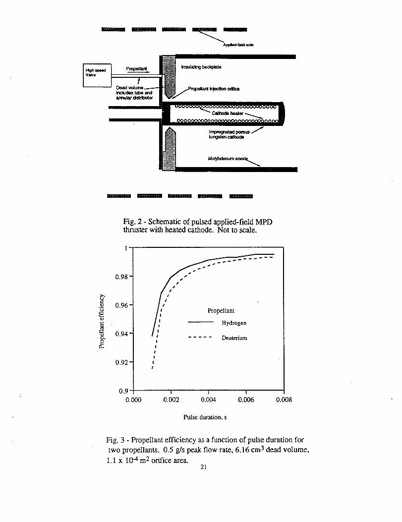
volume is approximately 6.2 cm 3. The propellant efficiency was calculated as a function of discharge duration
assuming that the current pulse ended at the same time as the high speed valve dosed, which conservatively assumes
that all the gas in the trapped volume is not accelerated. The result is shown in Fig. 3, from which it is seen that
the propellant efficiency exceeds 98% for pulse durations over 2.5 ms for both hydrogen and deuterium propellants.
For this work pulse durations between 1.5 and 2.5 ms were used for the system evaluation. Note that several groups
in Japan have successfully improved the propellant efficiency by adjusting the timing of the current pulse such thatit extends slightly beyond the valve closing, thus accelerating some of the gas in the trapped volume.17,25,2s, 29
Considerable effort has gone into the development of high speed, high reliability valves over the past several
years. The Japanese have developed a "Fast Acting Valve", FAV, which has operated reliably for over 3 x 10 6
pulses when used on an MPD thruster with a propellant mixture simulating hydrazine decomposition products.a2
The FAV has opening and closing times of approximately 150 l_s and has resulted in pulsed MPD thrusters with
apparently high propellant utilization efficiency with pulse durations of 1 ms. From another field, automobile fuel
injector valves are built to cycle 6xl0g times with a gas pulse duration of 2.5 ms and must remain within 6% oftheir start conditions for acceptance.a3 The latter is 2 to 3 times the number of cycles than will be required for a
LEO - GEO transfer mission. Peak operating temperature for both of these valve is - 100 "C, so heat transfer to
the valve results in a thermal control requirement. Both valves utilize less than 10 J per cycle. The Japanese FAV
weighs 0.3 kg, and an automotive fuel injector valve weighs 0.1 kg.
The thruster and applied-field masses were estimated by summing the component masses and adding a 20%
contingency. The component masses are given in Table 1, and the final result, for a thruster sized for a 40 kW
spacecraft, is 11.3 kg, yielding a thruster specific mass of 0.3 kg/kW. The same thruster could be used withoutmodification or performance degration at lower power levels by simply modifying the pulse frequency. This
capability permits very simple accomodation of decreasing spacecraft power during a mission resulting from array
degradation. Of course, if the initial spacecraft power were decreased, then the anode, applied-field coil, and insulatormasses could be reduced by using lighter materials and thinner walls.
Thruster Mounting Structure and GimbalsGimbals will likely be required on SEOTV's to minimize unwanted disturbance torques resulting from thrust
vector misalignment.34 Alternative reaction control systems are likely too heavy when sufficient propellant is
included.34 The thruster mounting structure mass is estimated as 30% of the thruster mass, and gimbal mass is
modeled as 309o of the thruster mass plus the mounting structure mass.35,36,37 These relations yield a mounting
structure and gimbal specific masses of 0.09 kg/kW and 0.12 kg/kW, respectively.

Power Management and DistributionThe power management and distribution system consists of the solar array, spacecraft bus, charge control unit,
pulse forming network, cathode heater supply, and high speed valve supply. No igniter supply is needed for the
proposed MPD thruster because the hot cathode is a ready supply of electrons. Low voltage ignition with heatedcathodes has been well established. 3s
Solar Array. - One near-term option for the solar array is the Advanced Photovoltaic Solar Array (APSA).
Estimates of APSA specific mass show that unless strongly shielded it would start a LEO-GEt transfer mission at
8.3 kg/kW and end near 20 kg/kW,39 so that an array with a beginning of life (BOL) power of 40 kW would have an
end-of-life (EOL) power of 16.6 kW. Adding 0.03 cm of shielding reduces the fractional change in specific mass,
but the array performance still degrades from 18 to 28 kg/kW over the course a 200 day transfer. The large
degradation in array power which can be expected during the course of an orbit transfer mission reemphasizes the
requirement for the propulsion system to accommodate power level changes without performance penalties. Whilethere are alternative technologies which may improve the array specific mass to between 6.5 kg/kW (BOL) and 7.8
kg/kW (EOL), 40 this study assumed a constant value of 12 kg/kW for all propulsion system options. Time
dependent array degradation was not included. In addition to the solar panels, a mechanism for panel deployment andorientation control must be provided. The mass of this system was estimated at 5.6 kg/kW, based on the results of a
General Dynamics SEOTV study, which resulted in an overall solar power supply specific mass of 17.6 kg/kW. 41
Charge Control Unit. - The charge control unit, or CCU, is very similar to an arcjet power processor unit
(PPLD which operates at constant power. Current plans call for the Electric Propulsion Insertion Transfer
Experiment (ELITE) spacecraft to incorporate a peak power tracker, which win yield a flight-packaged PPU specific
mass of 3 kg/kW at 10 kW with 94% efficiency. 42 In this study the CCU specific mass was set equal to that of an
arcjet PPU and was assumed to be constant for power levels between 10 and 40 kW.
Cathode Heater Supply. - The cathode heater supply, CHS, is required to heat the cathode to 1050 "C so as
to ensure adequate thermionic emission. The heater power requirement was determined above to be between 390 and
670 W. This power level will only be required during the start-up phase because discharge losses will supply a largefraction of the cathode heat once the thruster is operational. There are several efforts underway around the world to
develop flight-qualified hollow cathodes which require heaters and the associated supplies.43-45 For this study, a
high voltage heater was assumed and the CHS mass was set to 3 kg, which is equal to that of a flight-qualified 1
kW arc-jet PPU which operates at 93 % efficiency.
Pulse Forming Network. - The largest additional component of a pulsed propulsion system is the energy
storage unit or pulse-forming network (PFN). The PFN consists of a ladder network of capacitors and inductorstailored to provide the required current pulse shape and duration. To first-order, the PFN mass for a single string
propulsion system is proportional to the energy per pulse, which is determined from the mission total impulse, the
number of pulses per thruster, the number of thrusters required to perform the mission, and the thruster performance:
Itlspgo
Ep= 2Np Ntrlt (1)
which assumes a single string PFNlthruster system. Combining this result with the relationship for capacitor
energy storage and introducing the capacitor specific mass, ok, we obtain the approximate PFN capacitor mass:
7

ItI,pgoO_M¢ -
NpNdhV_ (2)
This equation illustrates the benefits of high voltage energy storage, providing that the capacitor specific mass is nottoo large and that the PFN can be matched to the thruster. Note that Equation (2) is not explicitly dependent on the
pulse duration, which only enters in establishing the peak thruster power.
(3)
For a constant discharge current, Equations (2) and (3) show that the pulse duration can have a large, though indirect,effect on the PFN mass via its impact on the pulse power and thus on the pulse voltage. In general, these simple
scaling rules indicate that PFN mass increases with mission total impulse and thruster specific impulse, anddecreases with increasing number of pulses, number of thrusters, thruster efficiency, and discharge voltage.
Detailed assessment of the PFN mass requires a more complete examination of the impacts of PFN design and
capacitor characteristics. A code was written which permitted rapid evaluation of the PFN component mass as afunction of mission and capacitor characteristics, total number of pulses, thruster performance, pulse duration, andnumber of PFN stages. The PFN configuration variables considered in the code are illustrated in Fig. 4. Therequired capacitance and inductance per PFN stage were calculated from:46
Xp XpZoLs,-
Cs = 2NsZ o 2Ns (4)
The number of capacitors in series within each PFN stage was calculated by dividing the PFN charging voltage,which is twice the thruster discharge voltage, by the rated capacitor voltage. Resistors required to maintain equal
voltages across the series capacitors were included. The number of parallel capacitor sets within a stage was thencalculated given the capacitance per stage. The number of extra capacitors needed to ensure adequate PFN lifetimewas estimated from the reliability data for each capacitor type, given in percent failure per one thousand hours at agiven voltage. Tlais estimate does not account for the lifetime dependence on the number of charge/discharge cycles,because those data were not available for several capacitor types, but rather used the number of total hours ofcharging time. The number of silicon controlled rectifiers, SCRs, was calculated by dividing the discharge currentby the rated current capability of the SCR and adding two to ensure adequate margin. No failure rates were availablefor the SCP,s, so it was not possible to estimate lifetimes. The inductor geometry was a fiat spiral. The inductor
mass was minimized by varying the spiral geometry while maintaining the required inductance. The code calculatedtotal component masses and PFN power losses during the charge and discharge phases of operation.
Metallized film, both tantalum and aluminum electrolytic, and ceramic capacitors were evaluated. The
capacitor designations and characteristics, obtained from vendor catalogs or other published data, are provided inTable 2. 47-50 The aluminum electrolytic capacitors were included to illustrate the potential advantages of improvedcapacitors even though they are not considered suitable for long-term space application due to their poor reliability.5OThe potential impact of newer double-layer capacitor technology under development at the Space Power Institute ofAuburn University 51 is discussed below.
PFN component masses were calculated for a LEO - GEO transfer mission with a velocity increment of 6000trds and total impulse of 2.6 x 10⁷ N-s. The mission velocity increment includes a plane change maneuver, and thetotal impulse was obtained by establishing the spacecraft and mission characteristics as discussed below and thenmultiplying the time average thrust by the trip time. In addition, it was assumed that two thrusters had to beoperating simultaneously, and the thruster efficiency was set to 0.5 for all cases. All other parameters were varied
8

over a wide range to establish trends in PFN mass. The PFN code was run for MPD thruster specific impulsesbetween 2000 and 6000 seconds, discharge durations between 1.5 and 4 ms, current levels between 5 and 10 kA, and
for a total number of pulses between 2 x l0 g and8xl08. This number of pulses ranges from a factor of 3 below to30% above the number for which automobile fuel injectors are currently qualified. These parameter ranges
correspond to thruster pulse frequencies from 1 to30 Hz and peak thrust levels from 20 to 50 N.
Results showed that changing the number of PFN stages from 4 to 8 resulted in less than a 2% change in the
PFN component mass. This result justified use of a 4 stage PFN, which has been shown to provide an adequately
fiat topped pulse on flight systems. 52 Typical code results for a 4 stage PFN are given in Table 3, in which the
number of capacitors and the PFN component masses are provided for a set of two 4000 s Isp thrusters with 50%
efficiency and 3 x 10 s pulses per thruster. The pulse duration was 2 ms. From Table 3 it is clear that the
aluminum electrolytic capacitors, which are the least suitable for long duration space missions, yield the lowest partscount and PFN mass. Next in order of increasing PFN mass are the ceramic, metallized film, and tantalum
electrolytic capacitors. For the case shown there is not much difference between the lighter ceramic and thealuminum electrolytic. Note that in both cases the specific mass of the PFN components would be below 5.5
kg/kW for a 10 kW spacecraft. In addition, for all cases the PFN efficiency is over 97%, with approximately one
half of the losses occurring across the SCRs.
For almost all discharge current and specific impulse combinations it was possible to find choices of pulse
duration and number of pulses for which either the ceramic or metallized film capacitors yielded PFN component
masses below 55 kg. This lack of sensitivity to thruster operating condition is important because it is not yet
possible to specify the operating conditions for a high performance MPD thruster. However, the PFN mass scaling
is not simple because of the coupling between the number of series capacitors, the discharge voltage, and the thruster
performance. This coupling is illustrated in Fig. 5, which shows the variation in PFN mass as a function of
thruster Isp for the metallized film, Z5U ceramic, and the lighter of the tantalum capacitor types with a constant
discharge current of 7.5 kA. Physically this variation in thruster performance would be obtained by varying thenumber of coils in the applied-field magnet to increase the applied-field strength, and thus the specific impulse, with
a constant discharge current. For a given number of capacitors, the PFN mass decreases with increasing specific
impulse until the discharge voltage increase forces the addition of another layer of capacitors. These results are notthe lowest obtainable PFN component masses because both the discharge duration and number of pulses were heldconstant for all cases. These data illustrate that a single capacitor type is not optimal for all thruster and mission
performance levels. PFN component mass is not sensitive to spacecraft power level, which is accounted for via the
heat rejection system mass. Estimates of packaging requirements for flight type power electronics result in a factorof 2 increase in mass over the component masses, 53 yielding a constant PFN mass of 110 kg using off-the-shelf
capacitor technology. As with the thruster, the PFN thermal control system can be designed for the maximum
mission power level, and decreases in power level due to solar array degradation can be accomodated simply by
changing the pulse frequency.
High Speed Valve Supply. - Fuel-injector valves require a 12V, 5A square wave of duration equal to the
thruster pulse length. A mass allocation of 1 kg was considered conservative for a fuel injector valve supply. The
Japanese FAV power supply is combined with a trigger supply for the thruster discharge. Both the FAV and trigger
supply are driven by small capacitor discharges and the combined weight of the system is 5 kg. 5° Based on these
data, a mass of 2 kg was used for the valve power supply in this study.
Thermal Management for CCU, PFN, and Cathode Heater Supply
The power system components requiring temperature control are the CCU, PFN, cathode heater supply, and the
high-speed valve supply. Requirements for the CCU are very similar to arcjet power processors, and temperaturelimits will likely be similar. Arcjet power processor baseplate temperatures are currently 50 °C during operation.
Similarly, the cathode heater and high-speed supplies will be limited to 50" C. The only components of the PFN
requiring temperature control are the capacitors and SCRs, which are typically limited to below 80 ° C. 47-s°
Severalauthorshavedevelopedsimplewaysto estimate thermal control system masses for ion thruster based
propulsion systems. Byers37 based his formula on a detailed study of ion propulsion systems by Hawthorne, -_ and
arrived at a specific thermal control system mass of 31 kgikW of rejected heat for an assumed baseplate temperature
of 50 ° C and a radiator heat rejection of 0.35 kW/m2. Hardy36 updated those results to arrive at a specific mass of
27 kg/kW. Later analyses by Brophy and Aston35 distinguished between heat generated by the ion thruster PPU's
and the power subsystem, with a specific mass of 20.5 kg/kW for the PPU's and 31.8 kg/kW for the power
subsystem thermal control units. They also used a PPU baseplate temperature of 50 ° C. The power subsystem in
their study included the high voltage power distribution unit, the low voltage power distribution unit, the DC/DC
converter, and the battery system. Hermel, et al.55 used more conservative values of radiator specific mass (11
kg/kVO, but did not call out the other elements of the rest of the heat rejection system, so it was impossible toestablish a total mass value for this subsystem. More recent studies for both communications and Earth-observing
satellites arrived values closer to the 30 kg/kW mentioned above. Price et al.-_ used a specific mass for thermal
controlof29.5kg/kW for3-axisstabilizedgeosynchronouscommunicationssatellitesand Pidgeon57 useda valueof
40 kg/kW based on historicaldata and technology forecasts.However, Pidgeon's analysiswas for the entire
spacecraft,includingheatrejectionforthebus,power source,and payloadheatrejection,whereas theearlierstudies
reflectedonly therequirementsof the propulsionsystem. Based on thisreview ofpreviouswork, a heatrejection
system specificmass of30 kg/kW ofheatrejectedby allthepropulsionpower systemswas selected.
Propellant Storage and DistributionSeveral recent studies have examined the long term storage of cryogenic hydrogen for hydrogen arcjets. A
General Dynamics study, 41 building on the capabilities of the Centaur upper stage, found that the tankage fraction
for a 200 day LEO - GEO transfer mission was 0.18 including the tank, insulation, and micrometeoroid protection.
The single-fault tolerant propellant feed system, including the compressors needed to boost the propellant supply
pressure to the required 2.75 x 10⁶ Pa and redundant high-pressure accumulators, weighed 74 kg. The compressorswould not be required for the lower pressure pulsed MPD thruster system as the tank pressure of I x 105 Pa would
be sufficient, and the reduction in feed pressure and flow rate would also reduce the mass of the other propellant feed
system components. The tank pressure is maintained at this level throughout the mission by a small heater in thetank. For this study the tankage fraction was kept constant at 0.18 and the mass of the propellant feed system was
reduced to 37 kg for the pulsed MPD thrusters. As discussed above, the high-speed valves were included in the
thruster component.
The use of deuterium propellant in pulsed MPD thrusters has two potentially large benefits. First, the factor of
two increase in propellant storage density will reduce the tankage fraction to 0.09. Second, the tank volume will
also be reduced by a factor of approximately two, which could mitigate the need for a new launch vehicle fairing
required for hydrogen arcjets. 41 Of course, the new fairing may not be required with hydrogen propellant either,
because the higher specific impulses associated with MPD thrusters greatly reduces propellant requirements compmed
to arcjets.
Pulsed System Integration Issues
Many pulsed electromagnetic propulsion systems with peak powers between 1 and 3 MW have been flown both
operationally and as experiments.9,10 Qualification of these systems has required evaluation of structural interfaces,electromagnetic interference, plume property distributions, spacecraft contamination, and thermal loads. The most
important of these which are relevant to pulsed MPD thruster systems are EMI and plume property distn'butions,where the latter are a concern due to the potential impact on communication signals. EMI has been extensively
studied in this country for 2 - 3 MW peak power, microsecond duration, pulsed-plasma thrusters and by the Japanese
for pulsed MPD thrusters.6, 7.9-11 Potential issues were identified in both cases which were corrected via simple
modifications of the power system. Minor interference resulting from the f'tring of the pulsed plasma thruster on the
NOVA I spacecraft was eliminated on NOVA II and III. 10 Plume property distributions for pulsed MPD thrusters
10

arenot well known for distances beyond 30 cm from the exit plane, so it is not possible to comment quantitatively
on their impact on communication signals. However, no issues of this type were reported on the MS-T4 flight of
an ammonia applied-field thruster.5
Propulsion System Comparison
A simple model was written to quantify the mission trades associated with using a pulsed MPD thruster system
and to compare the results with those attainable using hydrogen arcjets. A LEO - GEO transfer mission including a
plane change, with a total velocity increment of 6000 m/s, was analyzed for payloads between 1000 kg and 2000 kg
and spacecraft power levels between 10 and 40 kW. These values were chosen to span the range of other studies
using hydrogen arcjets and to examine the power - Isp trade-offs of LEO - GEO transfer missions. The effects of
eclipse and drag were not explicitly included in this study. Hermel et al. 55 found that approximately 9% of a low
thrust LEO - GEO transfer would be spent in eclipse resulting in a corresponding increase in trip time. While drag
was not explicitly included in this study, the 370 km initial altitude did not significantly penalize a 30 kW SEOTV
studied by General Dynamics. 41
A summary of the pulsed MPD thruster and hydrogen arcjet system masses is given in Table 4. Two thrusters
were assumed to be operating simultaneously for spacecraft control. Six hydrogen arcjets, each with a single string
power processing unit, were assumed based on an expected thruster lifetime of 1750 hr. 41 As discussed above, the
lower power, temperatures, and current densities present in the pulsed MPD thruster yield an expected lifetime of5000 hrs, resulting in a requirement of four MPD thrusters for a 200 day mission. This allows for failure of two of
the thrusters without affecting the mission. Single-string propulsion systems were assumed, so that each thruster
had a complete set of the power supplies shown in Fig. 1. The same PFN and MPD thruster masses were used for
the entire power range, with power scaling accomplished by changing the pulse frequency.
The final spacecraft mass was calculated for both the hydrogen arcjet and pulsed MPD thruster cases by solving
the rocket equation for the final mass, Mr, in terms of all the known spacecraft masses, the mission velocity change
and thruster specific impulse, and the tankage fraction. A five percent propellant contingency was added and the
result increased by 30% for additional contingency. The result was:
Mf =1. 3 x (Mp._. + M_, + Mp._. + M_ + Mpay)
tl - [l'05Tr + 0"05_exp/AV /- 1]}1_ _ I_pgo J(5)
where Mp. s is the propulsion system mass which includes all the power supplies needed for all thrusters, Mpow is
the power system mass which includes the arrays and their deployment and control mechanism, and Mp.e. is the
propellant management system mass which includes all the all tank utilities. The initial spacecraft mass in lowearth orbit (IMLEO) was calculated using the result for Mf and reapplying the rocket equation. Trip time was
evaluated by dividing the propellant mass by the total propellant flow rate, where the latter was obtained from the
flow rate to each thruster:.
rh = 2rl,P,2 2
I_,go (6)
and multiplying the result by the number of thrusters in operation. In this equation Pt is the power actually
delivered to the thruster, which accounts for both CCU and PFN losses. For the pulsed thrusters Pt is equal to Pp,
and Equation (6) yields the peak flow rate during the pulse. This was rescaled to the average flow rate by
11

multiplying by the pulse duration and the pulse frequency.
For this study the hydrogen arcjet performance was set to 1200 s Isp at 45% efficiency, 41 values which
overestimate the capabilities of current arcjets. Based on the recent results from Princeton 16 and Japan, 17 the MPD
thruster efficiency was set to 50% and the specific impulse was varied between one and five times the arcjet specific
impulse. While this may overestimate the performance of the MPD thruster at low specific impulses, there has notbeen sufficient study of pulsed H2 or D2 applied-feld MPD thrusters to establish optimum performance levels. A
370 km initial orbital altitude was used based on the General Dynamics SEOTV study.41
Figure 6 shows IMLEO for 10, 20, 30, and 40 kW spacecraft with a 1000 kg payload for both hydrogen arcjets
and pulsed MPD thrusters. The payload capabilities of four launch vehicles to the 370 km initial orbit are alsoshown.41,58 The IMLEO for the hydrogen arcjet based systems are 4350, 5250, 6140, and 7040 kg for the 10, 20,
30, and 40 kW power levels, respectively. The mass benefits of the higher Isp pulsed MPD thruster are clearly
evident for all power levels. As expected, for equal values of Isp the pulsed system penalizes the spacecraft mass
when compared to the H2 arcjet system, resulting in mass increases of about 800 kg for a 10 kW spacecraft. These
penalties, which result from the 110 kg PFN mass and the assumed single-s_ing system approach, force an increase
in launch vehicleclass for a 1200 s Isp pulsed MPD thruster. However, the advantages of the pulsed MPD thruster
are clear for higher specific impulses. The spacecraft IMLEo decreases rapidly with increasing specific impulse and
asymptotes to approximately 3200, 3700, 4200, and 4800 kg for the 10, 20, 30 and 40 kW spacecraft, respectively.These values reflect IMLEO reductions of up to 3000 kg for specific impulses above 4000 s. The spacecraft mass
breakdown for the 40 kW, 4000 s Isp hydrogen pulsed MPD thruster propelled spacecraft, using subsystems as
defined in Eqn. (5), is given in Table 5. The table shows that, for this example, the highest leverage technologies
are the spacecraft power and propulsion systems. As is clear from Fig. 6, the mass savings resulting from use of
higher Isp pulsed MPD thrusters can be used to reduce the launch vehicle class. Increasing the Isp to approximately
2000 s permits use of a smaller launch vehicle for every power level studied, and for most cases increasing Isp to
over 2100 s allows a further launch vehicle class reduction. For example, the 20 kW pulsed MPD thruster operating
at 1200 s Isp would require an Atlas HA launch vehicle, but increasing the Isp to 2200 s allows use of a Delta 7920.
The 20 kW arcjet system would requi_e an Atlas I vehicle. The 40 kW pulsed MPD thruster spacecraft at 1200 s Isp
could not be launched on the Atlas IIAS, but if operated at 3000 s it could use an Atlas I, and at 4000 s Isp it could
be launched on a Delta 7920. A 40 kW H2 arcjet requires an Atlas IIAS for launch.
Of course, as shown in Fig. 7, there are trip time penalties associated with the higher specific impulses. For
equal values of Isp, the two propulsion systems accomplish the LEO - GEO transfer in about the same time, and the
pulsed MPD thruster system trip time increases approximately linearly with Isp. At a power level of 10 kW neither
H 2 arcjets nor pulsed MPD thrusters can accomplish the orbit transfer in less than 330 days. For higher power
levels both the absolute magnitude of the trip time and its rate of increase with Isp decrease rapidly, reaching a
minimum value of 130 days at 40 kW and 1200 s Isp. The 40 kW system trip time achieves a trip time of 300
days at an Isp of 4000 s. For cases in which the launch vehicle is fixed by other constraints the propulsion system
trade-offs are only between trip time and power level. For example, from Fig. 6 it is seen that if the launch vehicleis constrained to a Delta 7920 the maximum arcjet power level is approximately 10 kW with a trip time of 330
days. The pulsed MPD thruster would require specific impulses of 2000, 3000, and 4000 s for power levels of 20,30, and 40 kW, respectively, for launch on the Delta 7920. The corresponding trip times are 260, 280, and 300
days, yielding trip time savings of 70, 50, and 30 days over that achieved with the H 2 arcjet
These propulsion system trade-off trends axe duplicated for a heavier 2000 kg payload. As shown in Figures 8
and 9 for spacecraft power levels of 20 and 40 kW, the heavier spacecraft reduces the penalty associated with using a
low Isp pulsed MPD thruster system and precludes use of the Delta 7920. The reduced mass penalty at low Isp is
12

dueto the smaller propulsion system mass fraction for the higher total spacecraft masses. For the heavier payload
neither the H2 arcjet nor the pulsed MPD thruster can be launched on an Atlas IIAS, and there is almost no launch
margin with the 30 kW H2 arcjet system. For an Isp of 2300 s a 30 kW pulsed MPD thruster system can be
launched on an Atlas IIA, and at 4000 s Isp it can be launched on an Atlas I. Use of a 40 kW, 3600 s Isp, pulsed
MPD thruster permits use of an Atlas IIA with a trip time of 300 days. To achieve a trip time lower than 200 days
using a single string propulsion system having a 110 kg PFN, either the specific impulse must be below 2000 s or
the spacecraft power must be increased over 40 kW.
The impacts of improved PFN technology and the use of deuterium propellant were examined by reducing the
PFN mass to a constant 55 kg and reducing the tankage fraction to 0.09. No other changes were made. As
discussed above, the power system mass is a dominant element of pulsed thruster systems, and PFN mass reduction
would require use of advanced capacitor technologies such as those being developed at the Space Power Institute ofAuburn UniversitySl and the Lawrence Livermore National Laboratory.59 A principal benefit of the use of
deuterium propellant would be the volume reduction of the propellant tank and its impact on launch vehicle payload
fairing requirements. IMLEO reduction and trip time estimates resulting from use of a 55 kg PFN are shown in
Figs. 10 and 11 for a 1000 kg payload and 40 kW spacecraft, from which it is seen that the lower PFN masseliminates almost all of the mass penalty at low values of Isp, and reduces the trip time by between 10 and 25 days
for missions lasting less than one year. The effect of using deuterium propellant and of combining the use of 152
with a low mass PFN on IMLEO reduction are shown in Fig. 12. As with the PFN mass reduction, using D2
propellant eliminates the mass penalty associated with operating the pulsed MPD thruster at the same Isp as the H2
arcjet, but the benefit of D2 decreases with increasing Isp because of the reduction in propellant mass. The
combined use of D2 propellant and an advanced technology PFN results in a lower system mass for the pulsed MPD
thruster for all values of Isp, and would permit use of a Delta 7920 launch vehicle with a 40 kW spacecraft using a
thruster having 3000 s Isp. Figure 13 shows that, for a given specific impulse, the advanced technologies result in a
20 day decrease in trip time for a given Isp. More dramatic, however, is the effect on the trip time for a given launch
vehicle. As discussed above, for the H 2 arcjet to be launched on a Delta 7920 the power level must be decreased to
approximately 10 kW with an associated trip time of 330 days. A pulsed MPD thruster system using D2 propellant
with a 55 kg PFN operating at 3000 s specific impulse could also be launched on a Delta 7920, but the trip time is
only 200 days. This result clearly shows that large benefits result from using D2 and reducing the PFN mass. No
attempt was made to quantify the potentially dominant benefits of D 2 propellant usage resulting from the propellant
tank volume reduction.
Conclusions
The system requirements for pulsed MPD thruster based solar-electric orbit transfer vehicles were studied toestablish the component and spacecraft masses for LEO - GEt. transfer missions at power levels from 10 to 40 kW.
Potential benefits of pulsed MPD thrusters over alternative electric propulsion concepts include ease of power scaling
required by array degradation or increased distance from the sun, improved transportability from low power flight
tests to operational vehicles, and reduced in ground qualification costs. In addition to the thruster and propellant
management system, a pulsed MPD thruster propulsion system requires a charge control unit, a pulse formingnetwork, a cathode heater supply, and a high speed valve supply. Propellant efflciencies greater than 98% appear
achievable via careful design of the propellant injection system and use of either automobile fuel-injector valve or the
Japanese Fast Acting Valve technologies. Fuel injector valves are routinely qualified for 6 x 10⁸ pulses, which isbetween 2 and 3 times the number of pulses required for a LEO-GEt transfer mission. The pulse forming network
charge control unit appears similar in specific mass characteristics to arcjet power processing units. Off-the-shelf
13

capacitors can yield pulse forming networks sufficiently small so that the reduction in propellant mass resulting
from the higher specific impulses available from MPD thrusters more than offsets the additional power system mass.
A system comparison with hydrogen arcjets using 1000 and 2000 kg payloads revealed that the initial mass inlow Earth orbit can be reduced by between 1200 and 3000 kg by using pulsed applied-field MPD thrusters with
specific impulses between 2000 and 4500 s and power levels between 10 and 40 kW. The resulting mass andvolume reductionscan be used toreducelaunchvehicleclasswithan associatedreductioninlaunchcost.There isan
increaseintriptime with specificimpulsewhich may be acceptableforcertainmissions. For situationsinwhich
the launch vehicleselectionisdetermined by otherconstraints,use of a higherpower, higher specificimpulse,
pulsedMPD thrustersystem can resultinsignificanttriptimesavings.Use ofmore advanced capacitortechnologies
and/or deuterium propellantfurtherreduce launch mass and triptime,potentiallyyicldinga 130 day triptime
reductionfor1000 kg payloadlaunchedon a Delta7920. Inaddition,use ofdeuteriumgreatlyreducesthepropellant
volume and may eliminatethe need for largerlaunchvehiclepayload shrouds. The potentialsystem, mass,
volume,and costbenefitsindicatethatpulsedMPD thrustersareanaUractivcoptionfororbittransfervehicles.
References
1. Myers, R.M., Mantenicks,M.A., and LaPointe,M.R., "MPD ThrusterTechnology,"AIAA Paper 91-3568,
Sept.1991,see alsoNASA TM 105242.
2. Sovey, J.S. and Mantenieks, M.A., "Performance and Lifetime Assessment of MPD Arc Thnlster Technology,"
Journal of Propulsion and Power, Vol. 7, No. 1, Jan. - Feb. 1991, pp. 71 - 83.
3. SeikeL G.R., York, T.M., and Condit, W.C., "Applied-Field Magnetoplasmadynamic Thrusters for Orbit-
Raising Missions, Orbit-Raising and Maneuvering Propulsion: Research Status and Needs, L. Caveny, ed., Prog. inAeronautics and Astronautics Vol. 89, American Inst. of Aeronautics and Astronautics, New York, 1984, pp. 260 -
286.
4. Polk, J.E. and Pivorotto, TJ., "Alkali Metal Propellants for MPD Thrusters," AIA.A Paper 91-3572, Sept.
1991.
5. Kurild, K., Nakamura, K., and Morimoto, S., "MPD Thruster Test on Engineering Test Satellite," AIAA Paper
79-2071, Oct. 1979.
6. Kuriki, K., "The MPD Thruster Test on the Space Shuttle," Journal of Spacecraft and Rockets, Vol. 16, No. 5,
Sept. - Oct. 1979, pp. 326-332.
7. Kuriki, K., Kawashima, N., Sazaki, S., Yanagisawa, M., and Obayashi, T., "Space Experiments with Particle
Accelerators (SEPAC) Performed in Spacelab First," AIAA Paper 85-1996, Sept. 1985.
8. Sazaki, S., Kawashima, N., Kuriki, K., Yanagisawa, M., and Obayashi, T., "Vehicle Charging Observed in
SEPAC Spacelab - 1 Experiment," Journal of Spacecraft and Rockets, Vol. 23, No. 2, March - April 1986, pp. 194-199.
9. Myers, R.M., "Electromagnetic Propulsion for Spacecraft," AIAA Paper 93-1086, Feb. 1993.
10. Ebert, W.L., Kowal, SJ., and Sloan, R.F., "Operational NOVA Spacecraft Teflon Pulsed Plasma Thruster
System," AIAA Paper 89-2497, July 1989.
11. Shimizu, Y., Toki, K, Suzuki, H., Uematsu, K, Otsuka, T., Shiina, K, and Kunii, Y., "Development of MPD
14

Arcjet System EM for SFU-I,'" IEPC Paper 91-147, Proceedings of the 22nd International Electric Propulsion
Conf., Viarregio, Italy, Oct. 1991.
12. King, D.Q., "100 kWe MPD Thruster System Design," AIAA Paper 82-1897, Nov. 1982.
13. Rudolph, L.K., "Design and Benefits of Pulsed MPD Thruster Orbit Transfer Vehicles," IEPC Paper 84-81,
Proceedings of the 17th International Electric Propulsion Conf., Tokyo, Japan, May 1984.
14. Polk, J.E., Kelly, A.J., and Jahn, R.G., "Characterization of Cold Cathode Erosion Processes," IEPC Paper 88-
075, Proceedings of the 20th International Electric Propulsion Conference, Garmish-Partenkirchen, Germany, Oct.
1988.
15. Taylor, R.D., Burton, R.L., and Wetzel, K.K., "Preliminary Investigation of a Low Power Pulsed ArcjetThruster," AIAA 92-3113, July 1992.
16. Miller, G.E. and Kelly, A.J., "Hydrogen Performance Measurements," in Electric Propulsion Laboratory
Progress Report MAE 1776.38, Princeton University, Dept. of Mechanical and Aerospace Engineering, July - Aug.
1992.
17. Tahara, H., Sazaki, M., Kagaya, Y., and Yoshikawa, T., "Thruster Performance and Acceleration Mechanisms
of a Quasi-steady Applied-field MPD Arcjet," AIAA Paper 90-2554, July 1990.
18. Schoenberg, K., Gerwin, R., Henins, I., Mayo, R., Scheuer, J., and Wurden, G., "Preliminary Investigation of
Power Flow and Electrode Phenomena in a Multi-Megawatt Coaxial Plasma Thruster," NASA CR 191084, March
1993.
19. MikeUedes, P. and Turchi, P.J., "Application of the MACH2 Code to Magnetoplasmadynamic Arcjets," AIAA
Paper 92-3740, July 1992.
20. Shroff, A.M., Palluel, P., and Tonnerre, J.C., "Performance and Life Tests of Various Types of Impregnated
Cathodes," Applications of Surface Science, Vol. 8, North Holland Publ., 1981, pp. 36 - 49.
21. Forrest, S.M., Green, M.C., Herrmannsfeldt, W.B., and Palmer, R.B., "A Bombarder Heated Reservoir Cathodefor a 36 A/cm2 Hour Life Application," Varian Electron Device Business Unit, Presented at the 1992 Tri-
Service/NASA Cathode Workshop, Greenbelt, Md, March 1992.
22. Slutz, R. J., "A 10,000-hr Life Test of an Engineering Model Resistojet," NASA TM 103216, Oct. 1990.
23. Gallimore, A.D., Kelly, A.J., and Jahn, R.G., "Anode Power Deposition in Quasisteady
Magnetoplasmadynamic Thrusters," Journal of Propulsion and Power, Vol. 8, No. 6, Nov. - Dec. 1992, pp. 1224 -
1231.
24. Myers, R. M., "Applied-Field MPD Thruster Geometry Effects," AIAA 91-2342, June 1991; See also NASA
CR 187163.
25. Yoshikawa, T., Kagaya, Y., and Tahara, H., "Continuous Operational Tests of a Quasi-Steady MPD Arcjet
System," IEPC Paper 91-075, Proceedings of the 22nd Intern. Electric Propulsion Conference, Viareggio, Italy, Oct.
1991.
26. Mantenieks, M.A. and Myers, R.M., "100-kW Class Applied-Field MPD Thruster Component Wear," 10th
Syrup. on Space Nuclear Power and Propulsion," AlP Proceedings No. 271, Jan. 1993, pp. 1317-1326, see also
15

NASATM- 106023.
27. Palumbo, DJ., "Solid Propellant Pulsed Plasma Propulsion System Development for N-S Stationkeeping,"
AIAA Paper 79-2097, Oct. 1979.
28. Tahara, H., Kagaya, Y., and Yoshikawa, T., "Hybrid MPD Thruster with Axial and Cusp Magnetic Fields,"
IEPC Paper 88-058, Proceedings of the 20th Intern. Electric Propulsion Conf., Garmish-Partenkirchen, Germany,
Oct. 1988.
29. Yoshikawa, T., Kagaya, Y., Tahara, H., and Wasa, T., "Continuous Operation of a Quasi-steady MPD Thruster
Propulsion System with an External Magnetic Field," IEPC Paper 88-056, Proceedings of the 20th Intern. Electric
Propulsion Conf., Garmish-Partenkirchen, Germany, Oct. 1988.
30. LaPointe, M.R., private communication, NASA Lewis Research Center, Cleveland, OH, 1993.
31. Jones, R.M., "propellant Injection for MPD Thrusters," AIAA 79-2074, Oct. 1979.
32. Suzuki, H., Uematsu, K., Ohtsuka, T., Shiina, K., Toki, K., and Shimizu, Y., "3 Million Shots Endurance
Test of 1 kW Class Arcjet Thruster," IEPC Paper 88-014, Proceedings the 20th Intern. Electric Propulsion Conf.,
Garmish-Partenkirchen, Germany, OCL 1988.
33. Bordewyka, T., personal communication, A.C. Rochester, Grand Rapids, MI, March 1993.
34. Rosenthal, R., Grethen, D., and Kdebel, M., "Design Integration of Electric Propulsion Systems," AIAA 93-
1083, Feb. 1993.
35. Brophy, J.R. and Aston, G., "A Detailed Model of Ion Propulsion Systems," AIAA 89-2268, July 1989.
36. Hardy, T.L., Rawlin, V.K., and Patterson, M.J., "Electric Propulsion Options for the SP-100 Reference
Mission," Proc. of the 4th Symposium on Space Nuclear Power Systems, The Institute for Space Nuclear Power
Studies, Albuquerque, NM, Jan. 1987.
37. Byers, D.C., Terdan, F.F., and Myers, I.T., "Primary Electric Propulsion for Future Space Missions" NASA
TM 79141, May 1979.
38. Sarver-Verhey, T.R., '`Extended Testing of Xenon Ion Thruster Hollow Cathodes," AIAA Paper 92-3204, July
1992, see also NASA CR 189227.
39. Stella, P.M. and Kultland, R.M., "Development Testing of the Advanced Photovoltaic Solar Array, Proc. of
26th IECEC, Vol. 2, Aug. 1991, p. 269-274.
40. SteUa, P.M. and Flood, D., "Photovoltaic Options for Solar Electric Propulsion," AIAA Paper 90-2529, July
1990.
41. Anon., "Feasibility of Applying Centaur Technology to an EOTV Propellant Storage and Management System,Final Presentation," General Dynamics, Space Systems Division, Contract NAS3-25972, Task Order No. 7, NASA
Lewis Research Center, July 31, 1992.
42. Caldwell, DJ., "System Design of ELITE Power Processing Unit," Proc. of26th lntersociety Energy
Conversion Engineering Conf. (IECEC), Aug. 4, 1991, p. 174-179.
16

43.Patterson, M., et aJ., "Plasma Contactor Technology for Space Station Freedom," Proposed AIAA Paper 93-
2228, June 1993.
44. Beattie, J.R., Robson, R.R., and Williams, J.D., "18-mN Xenon Ion PrOpulsion Subsystem," IEPC Paper 91-
010, Proceedings of the 22nd International Electric Propulsion Conf., Viarregio, Italy, Oct. 1991.
45. Lovell, M. "The UK-10 Power Conditioning and Control Equipment," AIAA Paper 90-2631, July 1990.
46. Humphries, S. Jr., Principles of Charged Panicle Acceleration, John Wiley and Sons, New York, 1986, pp.
254 - 262.
47. AVX Corporation, Ceramic Advanced Products, Cincinnati, OH 45211, 1993.
48. Sprague, Tantalum Capacitor Catalog, Stanford, Maine, 04073. 1993.
49. Mallory Capacitor Co., Electronic Components General Catalog, Indianapolis, Indiana 46241, 1993.
50. Kunii, Y., et al., "Verification of Performance and Endurance of Capacitor Bank for the Electric Propulsion
Experiment," IEPC Paper 88-048, Proceedings of the 20th Intern. Electric Propulsion Conf., Garmish-
Partenkirchen, Germany, Oct. 1988.
51. Rose, M.F., Private Communication, University of Auburn, Space Power Institute, Dec. 1992.
52. Told, K., Shimizu, Y., Kuriki, K., Suzuki, H., and Kunii, Y., "The MPD Arcjet Thruster System for Electric
Propulsion Experiment Onboard Space Flyer Unit," Proc. of the 17th International Symp. on Space Technology and
Science, Tokyo, Japan 1990.
53. Anon., "30-Centimeter Ion Thrust Subsystem Design Manual," NASA TM-79191, June 1979.
54. Hawthorne, E.I., et ai., "Extended Performance Solar Electric Propulsion Thrust System Study, Vol. III, Trad-
off Studies of Alternate Thrust System Configurations," Hughes Research Labs., Malibu, Calif. and Hughes Space
and Communications Group, Los Angeles, CA, Sept. 1977, see also NASA CR-135281.
55. Hermel, J., Meese, R.A., Rogers, W.P., Kushida, R.O., Beattie, J.R., and Hyman, J., "Modular, Ion-
Propelled, Orbit-Transfer Vehicle," Journal of Spacecraft and Rockets, Vol. 25, No. 5, Sept.-Oct. 1988.
56. Price, K.M., Pidgeon, D.J., and Tsao, A., "Mass and Power Modeling of Communications Satellites, NASA
CR 189186, Dec. 1991.
57. Pidgeon, D.J., "A Subsystem Design Study of an Earth Sciences Geostationary Platform," M.S. Thesis,
School of Engineering and Applied Sciences, The George Washington University, July 1989.
58. Anon., "Launch Vehicles Summary for JPL Missions," NASA JPL D6936, Rev. B, March 1992.
59. Mayer, S.T., Pekala, R.W., and Kaschmitter, J.L., "The Aerocapacitor: An Electrochemical Double-Layer
Energy Storage Device," J. Electrochem. Soc., Vol. 140, No. 2, Feb. 1993, pp. 446 - 451.
17

Component Mass, kg
Anode (Mo) 4.4
cathode(W) 2
Backplate/insulatof 1(Ano3)
Applied-field cod (Cu) 1.8
High speed valve 0.2
Contingency (20% of total) 1.9Total 11.3
Table 1 - 40 kW applied-field thruster mass breakdown
Capacitor Type (Ref.)
Metallized film (51)
Capacitance 0aV3 RatedVoltage(V) Mass (kg)
142 336 0.173
Ceramic (48) Z5U 460 200 0.183 50.3X7R 45 500 0.183 30.7
Tantalum (49) 81F 39 125 0.018 16.9112 28 200 0.025 22.4
Aluminum (50) CG 3000 250 0.95 98.7LP 680 250 0.454 46.8
Specific Energy (J/kg)
46
Table 2 -Capacitor characteristics used for PFN optimization.
18

Capacitor Type
Metallized Film
Number of Capacitors PFN Component Mass, kg
209 42.5
Ceramic Z5U 257 53.4
Ceramic X7R 657 126
Tantalum 81F 6802 129
• Tantalum 112 4214 111
Aluminum CG 41 45.3
Alumimlm LP 177 87
Table 3 - Typical results for PFN capacitor requirements and component masses for a LEO - GEOtransfer mission. 4000 s Isp, 50% efficiency, and 3 x 10⁸ pulses per thruster.
Component (Ref.)
Tankage Fraction (41)
Propellant Feed System (41)
Tank/Feed Venting (41)
Prop. Fill/Drain (41)
Boil-Off Control (41)
Thrusters
Thruster Mounting Str. (37)
Gimbals (37)
Attitude Control Syst. (41)
Solar Arrays (12)
Solar Army Control (41)
Power Processing Unit (42)
Charge Control Unit
High-Speed Valve Supply
Cathode He__ter Supply
Pulse-Forming Network
Thermal Management (37,65)
H2 Arcjet
0.18
Pulsed H2 MPDT
0.15 kg/kW
0.18
74 kg 37 kg
46 kg 46 kg
5 kg 5 kg
20 kg 20 kg
0.5 kg/kW 0.3 kg/kW0.09 kg/kW
0.20 kg/kW
125 kg
12 kg/kW
5.6 kg/kW
3 kg/kW
30 kg/kW
0.12 kg/kW
125 kg
12 kg/kW
5.6 kg/kW
3 kg/kW
2 kg
3 kg
110 kg
30 kg/kW
Pulsed D2 MPDT
0.09
37 kg
46 kg
5 kg
20 kg
0.3 kg/kW
0.09 kg/kW
0.12 kg/kW
125 kg
12 kg/kW
5.6 kg/kW
3 kg/kW
2 kg
3 kg
110 kg
30 kg/kW
Table 4 - Spacecraft mass breakdown for LEO - GEO transfer missions using H2 arcjets
and H 2 and D 2 pulsed MPD thrusters for power levels between 10 and 40 kW. Five
percent propellant contingency and thirty percent mass contingency added to all systems.
19

Subsystem
Propulsion,Mp.s.
Power, Mpow
Propellantcontrol,Mp.c
Mass, kg
955
7O4
270
Structure, Mstr 100
Tank 124
1000Payload,Mpa],Subtotal 3153
30% contingency 946
Propellant 693
Total IMLEO 4790
Table 5 - Mass breakdown for an 40 kW SEOTV using a 4000 s Isp hydrogen pulsed MPD
thruster with current technology capacitors. This spacecraft carries a 1000 kg payload,
has a triptime of300 days,and couldbe launched on an Delta7920.
e_
Eo
t_
t_
O
Propellantstorage anddistribution
system
I
I I] IPropellant thermalinjection ] ] control
_ytem _ I
MPD thruster
& gimbal
Cathode
Iheater
]
Fig. 1 - Pulsed MPD thruster propulsion system schematic.
2O
m m m _/
Valve iI f
Includestubeandannulardistrli_to¢
IiCall'_<lehealer
I_ted poroustungstencathode
m m m,,.,................
Fig. 2 - Schematic of pulsed applied-field MPDthruster with heated cathode. Not to scale.
¢.J
¢2
e'_
0.98
0.96
0.94
0.92 -
//
Propellant
Hydrogen
Deuterium#
!
I
I
!
1
0.9 I I I
0.000 0.002 0.004 0.006 0.008
Pulse duration, s
Fig. 3 - Propellant efficiency as a function of pulse duration for
two propellants. 0.5 g/s peak flow rate, 6.16 cm 3 dead volume,
1.1 x 10 -4 m 2 orifice area.21

• TTT TTT
Fig. 4 - PF'N schematic showing variable number of series (Ns) and parallel (Np)capacitors, inductor _ (Si), resistors (R), and number of silicon controlled
reaif_rs (SCRs).
E
e,-o
E00
200
150
I00
50-
0
Capacitor type----O---
CXTantalum 112 [_
Metallized film [ XCl
I I I !
1000 2000 3000 4000 5000 6000
Pulsed MPD thruster specific impulse, s
Fig. 5 - Unoptimized PFN component mass variation with thruster
specific impulse for 3 capacitor types. LEO - GEO transfer, pulse
duration 1.5 ms, 4 x 10 8 pulses per thruster.
22

<5
.=.
E
.'=_=
80OO
70OO
000-
5000-
000-
Q_ spacecraft power, kWAtlas IIAS MPDT _ 40
30,,.\ ....... _o, \ ....... ,o
. ',, \ _J_ o _o-\ []
\ '., \ A 20', \ Arias I, ". \, _- o _o
'_',. ', "-.,. __'. ',. "-.... _D_._ 7920
3000 i I !
1003 2000 3000 4000 5000
Pulsed MPD thrusterspecific impulse, s
Fig. 6 - Initial SEOTV mass in LEO vs. pulsed MPD thrusterspecific impulse for four spacecraft power levels. 1000 kgpayload, LEO - GEO transfer mission.
E
-r"
500
400-
300-
200
100
J o #
/ •s
/ •
### s S
• •s
.J • w .,/
• • .,I j
," //" /Spacecraft power,kW
...-" /.. .... _ ........A." 30
_/// .......20t5,'" / -- l•
Arcjet 0 40[] 3OA 2OO 10
I I I
1000 2000 3000 4000 5000
Pulsed MPD thruster specific impulse, s
Fig. 7 - Trip time as a function of pulsed MPD thruster specificimpulse. 1000 kg payload, LEO - GEO transfer mission
23

,..1°_
EN
e,e_
11000
10000-
9000-
8000-
7000
6000-
5000
1000
Spacecraft power, kWMPD thruster 40
....... 20Arc jet 0 40
A 2O
Arias IIAS
-. Atl_ I
I I i
2000 3000 4000 5000
Pulsed MPD thruster specific impulse, s
Fig. 8 - Initial mass in LEO vs. pulsed MPD thruster specificimpulse for 20 and 40 kW spacecraft. 2000 kg payload, LEO-GEOtransfer mission.
F-,
800
00-
4OO
200
0
Spacecraft power, kW40
20
O 40
A 20
s S
s _s
MPDT •s S
Aicje_ ."
S S
S •
S S
S •
• ••• •S•
••s
ss ,s
i i i
1000 2000 3000 4000 5000
Pulsed MPD thruster specific impulse, s
Fig. 9 - Trip time as a function of pulsed MPD thruster specificimpulse. 2000 kg payload, LEO - GEO transfer mission.
24

,-.1.=_
-=
8000
7000
000"
5000-
APFN mass, kg
I10
....... 55
O Arcjet
Delta7920
4000 i | i
1000 2000 3000 4000 5000
Pulsed MPD thruster specific impulse, s
Fig. 10 - Effect of PFN mass on initial mass in LEO vs pulsedMPD thruster specific impulse. 1000 kg payload, 40 kW spacecraft.
350
300-
_' 250
,sE
....i
m.-,- 200 -
150 -
m s,6 °....... 55 / ,,"
0 ._c.i_t 7 -'"
ssso °°S
ssss °°SS
osssss SSSSSS°S
,F
100 , , i1000 2000 3000 4000 5000
Pulsed MPD thruster specific impulse, s
Fig. 11 - Effect of PFN mass on trip time for a 40 kWspacecraft. 1(300kg payload, LEO - GEO transfer mission.
25

,.de_
E
o,.._°_
8000
7000
6000
Atlas IIAS Propellant, PFN mass
H2, ll0kg
....... I)2, II0 kg
I)2, 55 kg
0 Arejet
Delta 7920
I I I
l_ 2000 3000 4000 5000
Pulsed MPD thruster specific impulse, s
Fig. 12 - Effect of propellant choice and reduced PFN mass for a40 kW spacecraft. 1000 kg payload, LEO - GEO transfer mission.
350
300-
250-
E
".- 200b.
150
100
/O 10 kW arcjet
S S °S
J�s SB
_ _ dBJ
_ S oj_
40 kW arcjet _"_so S
/ /.;.,"_s S_
/,".,,'" Propellant, PFN mass
/.._.s _ H2. II0 kg
_'.'_.'* - ...... D2, 110 kg[] • S*
I I 1
1000 2000 3000 4_ 5000
Pulsed MPD thruster specific impulse, s
Fig. 13 - Impact of propellant choice and PFN masson trip time as compared to H2 arcjets. 1000 kg payload,LEO - GEO transfer mission.
26


Form ApprovedREPORT DOCUMENTATION PAGE OMBNo. 0704-0188
Public reporting burden for this collection of information is estimated 1o average 1 hour per response, including the time for reviewing instructions, searching existing data sources,gathering and maintaining the data needed, and completing _d reviewing the collection of information. Send comments regarding this burden estimate or any other aspect of thiscollection of information, including suggestions for reducing th_s burden, to Washington Headquarters Services. Directorata for Information Operations and Reports. 1215 JeffersonDavis H_Jhway, Suite 1204, Arlington, VA 22202-4302, and to the Office of Management and Budget. Paperwork Reduction Project (0704-0188), Washington, DC 20503.
1. AGENCY USE ONLY (Leave blank) 2. REPORT DATE 3. REPORT TYPE AND DATES COVERED
September 1993 Final Contractor Report
5. FUNDING NUMBERS4. TITLE AND SUBTITLE
Low Power Pulsed MPD Thruster System Analysis and Applications
s. AUTHOR(S)
Roger M. Myers, Matthew Domonkos, and James H. Gilland
7. PERFORMING ORGANIZATION NAME(S) AND ADDRESS(ES)
Sveredrup Technology, Inc.
Lewis Research Center Group
2001 Aerospace Parkway
Brook park, Ohio 44142
9. SPONSORING/MONITORING AGENCY NAME(S) AND ADDRESS(ES)
National Aeronautics and Space Administration
Lewis Research Center
Cleveland, Ohio 44135-3191
WU-506--42-31
C-NAS3-25266
8. PERFORMING ORGANIZATIONREPORT NUMBER
E--8099
10. SPONSORING/MONITORING
AGENCY REPORT NUMBER
NASA CR-191187
AIAA-93-2391
11. SUPPLEMENTARY NOTES
Prepared for the 1993 Joint Propulsion Conference cosponsored by the AIAA, SAE, ASME, and ASEE, Monterey,
California, June 28-July 1, 1993. Project Manager, James S. Sovey, Space Propulsion Technology Division,
(216) 433-7454.
12a. DISTRIBUTION/AVAILABILITY STATEMENT
Unclassified - Unlimited
Subject Categories 16, 20, and 75
12b. DISTRIBUTION CODE
13. ABSTRACT (Maximum 200 words)
Pulsed MPD thruster systems were analyzed for application to solar-electric orbit transfer vehicles at power levels
ranging from 10 to 40 kW. Potential system level benefits of pulsed propulsion technology include ease of power
scaling without thruster performance changes, improved transportability from low power flight experiments to
operational systems, and reduced ground qualification costs. Required pulsed propulsion system components include
a pulsed applied-field MPD thruster, a pulse-forming network, a charge control unit, a cathode heater supply, and
high speed valves. Mass estimates were obtained for each propulsion subsystem and spacecraft component using off-
the-shelf technology whenever possible. Results indicate that for payloads of 1000 and 2000 kg pulsed MPD thrusters
can reduce launch mass by between 1000 and 2500 kg over those achievable with hydrogen arcjets, which can be
used to reduce launch vehicle class and the associated launch cost. While the achievable mass savings depends on the
trip time allowed for the mission, cases are shown in which the launch vehicle required for a mission is decreased
from an Atlas IIAS to an Atlas I or Delta 7920.
14. SUBJECT TERMS
Magnetoplasmadynamic; Plasma dynamics; Electric propulsion
17. SECURITY CLASSIFICATIONOF REPORT
Unclassified
18. SECURITY CLASSIFICATIONOF THIS PAGE
Unclassified
19. SECURITYCLASSIFICATIONOF ABSTRACT
Unclassified
15. NUMBER OF PAGES
2816. PRICE CODE
20. LIMITATIONOF ABSTRACT
NSN 7540-01-280-5500 Standard Form 298 (Rev. 2-89)PrescribedbyANSI Stcl.Z39-18298-102