lt-888 udact-300a instr rev 6 - mircom | safer, … with nfpa 72 chapter 4 (supervising station fire...
TRANSCRIPT

UDACT-300ADigital Alarm Communicator Transmitter
LT-888 Rev 6 June 2017Installation and Operation Manual
1
*
5
8
0 #
ENTER
MENU
CANCEL
INFO
6
2ABC
3DEF
4GHI JKL MNO
7PRS TUV
9WXY
QZ
RS-485 COMMONTROUBLE
CPUFAIL LINE 1 LINE 2 POWER
ON

Table of Contents
1.0 Industry Canada and FCC Notice 5
1.1 Notice for all UDACTs Sold in Canada .......................................................................... 5
1.2 Industry Canada Notice ................................................................................................. 5
1.3 Notice for all UDACTs Sold in the U.S.A. ...................................................................... 5
1.4 FCC Notice .................................................................................................................... 6
2.0 Introduction and Features 7
3.0 Mechanical Installation and Dimensions 8
4.0 Connections and Settings 9
4.1 UDACT-300A MAIN BOARD ......................................................................................... 9
5.0 Field Wiring 11
5.1 UDACT-300A Main Board Terminal Connections .......................................................... 11
6.0 Power Up Procedures 12
7.0 Basic Operation and Supervision 13
8.0 Configuration Setup 14
8.1 Configuration with the On-board Keypad ....................................................................... 14
8.2 Configuration with UIMA and a Computer ..................................................................... 15
8.3 Configuration with a Modem and Computer .................................................................. 16
9.0 Configuration and LCD Operation 17
9.1 Entering the Passcode ................................................................................................... 17
9.2 Command Menu ............................................................................................................ 18
9.3 Test Dialer (Command-Menu) ....................................................................................... 20
9.4 Config Info (Command-Menu) ....................................................................................... 22
9.5 Version Info ................................................................................................................... 22
9.6 Set Time (Command-Menu) .......................................................................................... 23
9.7 Set Password (Command-Menu) ................................................................................... 24
9.8 Default Config (Command-Menu) .................................................................................. 24
9.9 Dialer Config (Command-Menu): ................................................................................... 25
9.10 Time Parameter Menu ................................................................................................... 35
3

Table of Contents
9.11 Dialer Enable/Disable ..................................................................................................... 36
9.12 Ring Detection ................................................................................................................ 36
9.13 Exit (Command-Menu) ................................................................................................... 37
10.0 Compatible Fire Alarm Control Panels 42
11.0 Connecting to a 3G4010/CF Interface Device 43
11.1 Connecting to a 3G4010 Interface Device for Canada .................................................. 43
11.2 Connecting to a 3G4010CF Interface Device outside Canada ...................................... 44
12.0 Compatible Receivers 45
13.0 Specifications 46
14.0 Battery Calculations 46
15.0 Warranty and Warning Information 47
4

1.0 Industry Canada and FCC Notice
1.1 Notice for all UDACTs Sold in Canada
Mircom's UDACT-300A Digital Communicator described in this manual is listed by Underwriters Laboratories Canada (ULC) for use in slave application in conjunction with a Listed Fire Alarm Control Panel under Standard ULC-S527 (Standard for Control Units for Fire Alarm Systems) and CAN/ULC-S561-13 (Standard for Installation and Services for Fire Signal Receiving Centres and Systems). These Communicators should be installed in accordance with this manual; the Canadian / Provincial / Local Electrical Code; and/or the local Authority Having Jurisdiction (AHJ).
1.2 Industry Canada Notice
Repairs to certified equipment should be made by an authorized Canadian maintenance facility designated by the supplier. Any repairs or alteration made by the user to this equipment, or equipment malfunctions, may give the telecommunications company cause to request the user to disconnect the equipment. Users should ensure for their own protection that the Earth Ground connections of the power utility, telephone lines and internal metallic water pipe system, if present, are connected together. This is necessary both for proper operation and for protection.
1.3 Notice for all UDACTs Sold in the U.S.A.
Mircom's UDACT-300A Digital Communicator described in this manual is listed by Underwriters Laboratories Inc. (ULI) under Standard 864 (Control Units for Fire Protective Signaling Systems). These Communicators comply with the National Fire Protection Association (NFPA) performance requirements for DACTs and should be installed in accordance with NFPA 72 Chapter 4 (Supervising Station Fire Alarm System). These Communicators should be installed in accordance with this manual; the National Electrical Code (NFPA 70); and/or the local Authority Having Jurisdiction (AHJ).
Note: This equipment meets the applicable Industry Canada Terminal Equipment Technical Specifications. This is confirmed by the registration number. IC: 1156A-UD300A The abbreviation, IC, before the registration number signifies that registration was performed based on a Declaration of Conformity indicating that Industry Canada technical specifications were met. It does not imply that Industry Canada approved the equipment.
Note: The Ringer Equivalence Number (REN) for this terminal equipment is 0.2. The REN assigned to each terminal equipment provides an indication of the maximum number of terminals allowed to be connected to a telephone interface. The termination on an interface may consist of any combination of devices subject only to the requirement that the sum of the Ringer Equivalence Numbers of all the devices does not exceed five.
Note: The Ringer Equivalence Number (REN) for this product is 0.2.
i
i
5

Industry Canada and FCC Notice
1.4 FCC Notice
This equipment complies with the Federal Communications Commission (FCC) rules and regulations governing telephone equipment and the Technical Requirements for Connection to the Telephone Network published by the industry’s Administrative Council for Terminal Attachments (ACTA). On the door of this equipment is a label that contains, among other information, a product identifier in the format US:1M8AL02BUDACT300A. If requested, this number must be provided to the telephone company. This equipment is capable of seizing the line. This capability is provided in the hardware.
The Ringer Equivalence Number (REN) assigned to each terminal device provides an indication of the maximum number of devices that may be connected to a telephone line. Excessive REN’s on a telephone line may result in the devices not ringing in response to an incoming call. In most, but not all areas, the sum of REN’s should not exceed five (5.0). To be certain of the number of devices that may be connected to a line, as determined by the total REN’s contact the local telephone company. The REN for this product is 0.2
Telephone Company Procedures: The goal of the telephone company is to provide you with the best service it can. In order to do this, it may occasionally be necessary for them to make changes in their equipment, operations or procedures. If these changes might affect your service or the operation of your equipment, the telephone company will give you notice, in writing, to allow you to make any changes necessary to maintain uninterrupted service.
In certain circumstances, it may be necessary for the telephone company to request information from you concerning the equipment which you have connected to your telephone line. Upon request of the telephone company, provide the FCC registration number and the ringer equivalence number (REN); both of these items are listed on the equipment label. The sum of all of the REN’s on your telephone lines should be less than five in order to assure proper service from the telephone company. In some cases, a sum of five may not be usable on a given line.
If Problems Arise: If any of your telephone equipment is not operating properly, you should immediately remove it from your telephone line, as it may cause harm to the telephone network. If the telephone company notes a problem, they may temporarily discontinue service. When practical, they will notify you in advance of this disconnection. If advance notice is not feasible, you will be notified as soon as possible. When you are notified, you will be given the opportunity to correct the problem and informed of your right to file a complaint with the FCC. Contact your telephone company if you have any questions about your phone line. In the event repairs are ever needed on the Communicator, they should be performed by Mircom Technologies Ltd. or an authorized representative of Mircom Technologies Ltd. For information contact Mircom Technologies Ltd. at the address and phone numbers shown on the back page of this document.
6

2.0 Introduction and FeaturesUDACT-300A is a single board Digital Communicator that can connect to a Mircom Fire Alarm
Control Panel (FACP) such as FA-1000, FX-2000, FleX-NetTM, and the MMXTM via an RS-485 data link and common relay connection on a single ribbon cable. It can transmit Zoned Alarm, Supervisory and Trouble information on two telephone lines to a Digital Alarm Communicator Receiver (DACR).
Features:
• Receives events from the FACP via an RS-485 data link and common relay connection.
• Communicates to a DACR using Ademco Contact ID or SIA DCS reporting protocols (300 baud or 110 baud rate).
• The UDACT-300A has the ability of disconnecting the incoming and outgoing calls and capturing the line for transmission to the DACR.
• Provides telephone line monitoring and reports status via LED indication on-board, yellow for trouble and red for dialing out.
• User configurable locally by on-board keypad and a CFG-300 Configuration Tool or using a UIMA and computer with serial port or USB. Remotely configurable via a Personal Computer modem.
• Provides event logs of 500 entries each to save events from local dialer or remote fire alarm panel. These logs can be reviewed locally with CFG-300 Configuration Tool or remotely via modem.
7

3.0 Mechanical Installation and DimensionsThe UDACT-300A board is a single PCB assembly, which is a replacement for the UDACT-100A. Any reference pertaining to the UDACT-100A regarding mechanical mounting can be adhered to. Its mechanical installation is determined by the Fire Alarm Control Panel (FACP) it will be installed in, and is described in the appropriate FACP Installation Manual. Figure 1
below shows the mechanical installation for an FA-1000, FX-2000, FleX-NetTM or MMXTM FACP.
Figure 1 UDACT-300A Mechanical Installation
Note:
1. Front plate is not shown2. Reserved for PR-300 and UDACT-300A3. Other circuit adder modules may be:• DM-1008A Detection Circuit Adder Module• SGM-1004A Signal Circuit Adder Module• RM-1008A Relay Circuit Adder Module• ALC-198S LOOP ADDER MODULE• ALC-396S, ALCN-396S or ALCN-792M, ALCN-792D DUAL/QUAD
LOOP ADDER MODULES• ALC-H16 HARDWIRE LOOP CONTROLLER MODULE
UDACT-300A DIALER MODULE
PR-300 CITY TIE MODULE
Model FA-1000, SFC-300, FX-2000, MMX or FleX-Net
i
8
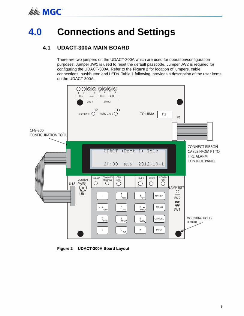
4.0 Connections and Settings
4.1 UDACT-300A MAIN BOARD
There are two jumpers on the UDACT-300A which are used for operation/configuration purposes. Jumper JW1 is used to reset the default passcode. Jumper JW2 is required for configuring the UDACT-300A. Refer to the Figure 2 for location of jumpers, cable connections, pushbutton and LEDs. Table 1 following, provides a description of the user items on the UDACT-300A.
Figure 2 UDACT-300A Board Layout
UDACT (Prot-1) Idle
20:00 MON 2012-10-1
CONNECT RIBBON CABLE FROM P1 TO FIRE ALARM CONTROL PANEL
9

Connections and Settings
Table 1 Cable Connectors and Miscellaneous
The following table lists all the LEDs located on the UDACT-300A board and states the function of each LED.
Table 2 UDACT-300A List of LEDs and their Functions
Cable Connector Function
P1 Ribbon Cable for connecting to Mircom Fire Alarm Control Panel (FACP)
P2 RS-232C/RS-485 Connection for computer configuration.
U18 Connector for CFG-300 Configuration Tool
Lamp Test buttonPress and hold this button to test all the UDACT-300A LEDs and LCD display
UR1 Potentiometer This potentiometer is for adjustment of the CFG-300 LCD contrast.
LEDs FUNCTION
Relay Line 1Located below Line 1 terminal block. When Line 1 relay is energized, this green LED will illuminate
Relay Line 2Located below Line 2 terminal block. When Line 2 relay is energized, this green LED will illuminate.
RS-485 Status LED for communication, will flash when RS-485 communication is active.
Common Trouble Steady amber for any troubles on the Fire Alarm panel or UDACT-300A.
CPU Fail Steady amber for any on board CPU trouble.
Telephone Line 1Telephone status indicator LED; Red when the line is in use, Amber when there is a line trouble.
Telephone Line 2Telephone status indicator LED; Red when the line is in use, Amber when there is a line trouble.
Power ON Green LED is ON steady when power is supplied to the board.
The following table lists the user jumpers available on the UDACT-300A and their functions.
Table 3 UDACT-300A List of Jumpers for Operation and Configuration
JUMPER NUMBER JUMPER FUNCTIONS
JW1
Normally open. Place jumper here and power down the UDACT-300A by disconnecting P1 or power down the fire alarm panel (AC and Batteries), then power back to revert to default passcode. After reset, remove the jumper. Leave normally open.
JW2
Normally open to BLOCK remote configuration via modem, PC with a UIMA converter module or using the LCD and keypad at the UDACT-300A. Place jumper here to ALLOW any type of configuration. Remove jumper once configuration is complete.
10

5.0 Field Wiring
5.1 UDACT-300A Main Board Terminal Connections
Wire the two telephone lines to RJ31X Connector terminals as shown in Figure 3 below. The UDACT-300A terminals are located on the top left hand corner of the board. If using a cellular or wireless service, use the Line 2 interface connection only. Dialer will try to report using Line 2 first.
Figure 3 Telephone Line Wiring Diagram
Note: Most Authorities Having Jurisdiction (AHJ) do not allow the connection ofpremise telephones. see specifications for more information.i
T TR R
premise telephoneIF permitted
T TR R
LINE-1 LINE-2
12 3
4
8 57 6
Public switchTelephone company
wiring
TIP
RING
TIP
RING
RJ31X
RED
GR
EEN
GR
EY
BRO
WN
RES RESC.O. C.O.
Line 2 is Wired as shown for Line 1
UDACT-300A
For cellular or wireless service use Line 2
11

6.0 Power Up Procedures 1. UDACT-300A board should be securely mounted mechanically into a Mircom FA-1000,
FX-2000, FleX-NetTM or MMXTM Fire Alarm Panel.
2. Check that the telephone lines are connected as shown in Figure 3.
3. Connect cable from P1 on the UDACT-300A board to the Fire Alarm Control Panel.
4. Connects to P2 for Mircom FA-1000 and P4 for the Mircom FX-2000 and FleX-NetTM
and MMXTM Fire Alarm Control Panels.
5. Connect the CFG-300 Configuration Tool to the U18 connector and place over the mounting studs on the UDACT-300A above the keypad and secure. This CFG-300 Configuration Tool can be removed once configuration has been completed.
6. Power up the Fire Alarm Panel and the message on the CFG-300 Configuration Tool should be:
Figure 4 CFG-300 Configuration Tool
UDACT(Prot-1)
00:00 SUN 2006-10-01
12

7.0 Basic Operation and SupervisionThe UDACT-300A can receive events from the FACP through the RS-485 data link and the common relay connections on the PR-300 ribbon cable. It will always report events sorted in the order in which they are received/recognized. When the dialer buffer is full, all new incoming events will be ignored. While working in the UDACT mode, the detailed zone information (event code with zone number) will be reported to the monitoring station. The UDACT-300A also monitors the communication on the RS-485 between the FACP and itself. If the sum of the RS-485 data link errors within 24 hours exceeds the predefined threshold, a Communication Trouble with ID# 485 will be reported during the 24-hour periodic test. While working in the DACT mode, UDACT-300A scans the common relay connections from the FACP (including Common Alarm, Common Supervisory and Common Trouble relays) and reports the common status only.
The UDACT-300A is capable of reporting multiple events to a single account number, within a single call session. For a single event not yet reported, up to 4 retries will be made within a single call attempt. A failure to report to either or both accounts will generate corresponding events that will be queued for reporting. Once the UDACT-300A fails to report on all telephone lines, it stops retrying, but an Alarm Event, Manual Test or 24-hour Periodic Test will force the UDACT-300A to seize the line and try reporting again. For two regular Telco telephone line connections, the UDACT-300A checks each line operation by reporting the 24-hour periodic test result on Line #1 or Line #2 alternately.
The UDACT-300A continuously supervises the status of each of two connected Telco Lines at approximately 1 minute intervals. The regular line supervision includes DC voltage level validation and dial tone detection. Line supervision is skipped while (1) the dialer is busy reporting, (2) the modem is working or (3) there is ringing on the line. If the line supervision fails, a Line #1 or Line #2 Trouble will be reported after a 30 second verification. Once the line has been restored, a Line Trouble Restore will be reported.
13
8.0 Configuration SetupThere are 3 ways of configuring the UDACT-300A.
• Locally with the on-board keypad and CFG-300 Configuration Tool.
• Locally with a Personal Computer via the RS-232 connection, a UIMA and the Dialer Configuration Utility software.
• Remotely with a computer, modem and the Dialer Configuration Utility software.
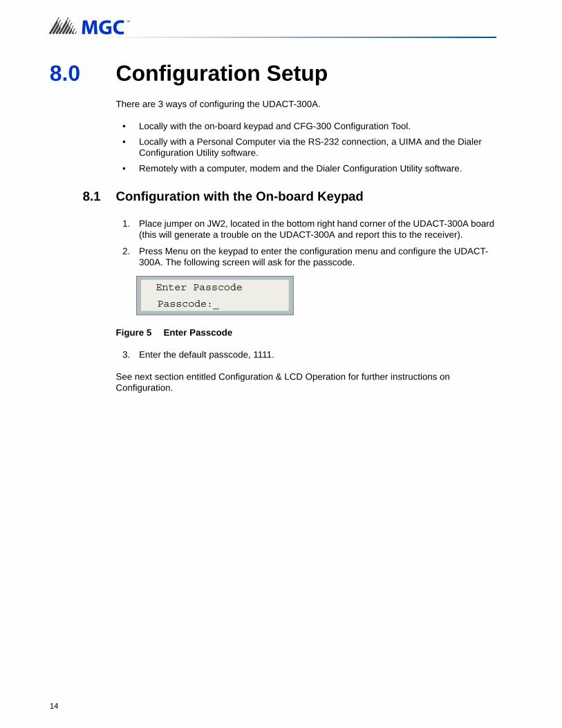
8.1 Configuration with the On-board Keypad
1. Place jumper on JW2, located in the bottom right hand corner of the UDACT-300A board (this will generate a trouble on the UDACT-300A and report this to the receiver).
2. Press Menu on the keypad to enter the configuration menu and configure the UDACT-300A. The following screen will ask for the passcode.
Figure 5 Enter Passcode
3. Enter the default passcode, 1111.
See next section entitled Configuration & LCD Operation for further instructions on Configuration.
Enter Passcode
Passcode:_
14

Configuration Setup
8.2 Configuration with UIMA and a Computer
You need the following items in order to connect the Configurator to the UDACT-300A:
• Windows computer with a serial port
• Serial or USB cable
• UIMA cable
• Dialer Configuration Utility - contact Mircom Customer Support at 888-647-2665
1. Contact Mircom Customer Support at 888-647-2665 to download and install the Dialer Configuration Utility.
2. Connect the serial or USB cable to the UIMA cable.
3. Connect the 10-pin cable connector of the UIMA to P2 on the UDACT-300A board.
4. Connect the other end of the serial or USB cable to the computer.
5. Place a jumper at JW2 on the UDACT-300A board to allow the configuration (a trouble is generated and reported to the receiver DACR).
6. Start the Dialer Configuration Utility.
7. Click the Tools menu, and then click Serial Port Settings.
8. Specify the following information:
• Port: The COM port that the UIMA cable is connected to
• Baud rate: 9600
• Parity: None
• Data bits: 8
• Stop bits: 1
Note: When you have finished configuring the UDACT-300A, remove the jumper onJW2. Otherwise a trouble will occur.i
15
Configuration Setup
8.3 Configuration with a Modem and Computer
1. Contact Mircom Customer Support at 888-647-2665 to download and install the Dialer Configuration Utility.
2. Set-up the modem connection on the computer. Make sure the phone line is working properly.
3. Place a jumper at JW2 on the UDACT-300A board to allow the configuration (a trouble is generated and reported to the receiver DACR).
4. Start the Dialer Configuration Utility.
5. Click the Tools menu, and then click Serial Port Settings.
6. Specify the following information:
• Port: The COM port that the UIMA cable is connected to
• Baud rate: 9600
• Parity: None
• Data bits: 8
• Stop bits: 1
Note: When you have finished configuring the UDACT-300A, remove the jumper onJW2. Otherwise a trouble will occur.i
16
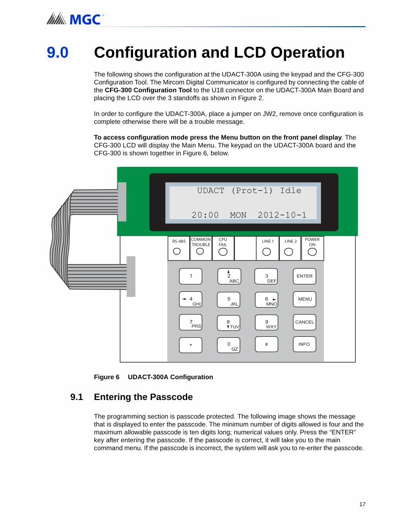
9.0 Configuration and LCD OperationThe following shows the configuration at the UDACT-300A using the keypad and the CFG-300 Configuration Tool. The Mircom Digital Communicator is configured by connecting the cable of the CFG-300 Configuration Tool to the U18 connector on the UDACT-300A Main Board and placing the LCD over the 3 standoffs as shown in Figure 2.
In order to configure the UDACT-300A, place a jumper on JW2, remove once configuration is complete otherwise there will be a trouble message.
To access configuration mode press the Menu button on the front panel display. The CFG-300 LCD will display the Main Menu. The keypad on the UDACT-300A board and the CFG-300 is shown together in Figure 6, below.
Figure 6 UDACT-300A Configuration
9.1 Entering the Passcode
The programming section is passcode protected. The following image shows the message that is displayed to enter the passcode. The minimum number of digits allowed is four and the maximum allowable passcode is ten digits long; numerical values only. Press the “ENTER” key after entering the passcode. If the passcode is correct, it will take you to the main command menu. If the passcode is incorrect, the system will ask you to re-enter the passcode.
UDACT (Prot-1) Idle
20:00 MON 2012-10-1
17
Configuration and LCD Operation
The system will be exhausted after three retries and will then take you back to the Normal message display. The default passcode is “1111” (without quotes).
Figure 7 Enter passcode
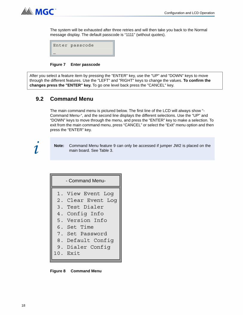
9.2 Command Menu
The main command menu is pictured below. The first line of the LCD will always show “-Command Menu-“, and the second line displays the different selections. Use the “UP” and “DOWN” keys to move through the menu, and press the “ENTER” key to make a selection. To exit from the main command menu, press “CANCEL” or select the “Exit” menu option and then press the “ENTER” key.
Figure 8 Command Menu
After you select a feature item by pressing the "ENTER" key, use the "UP" and "DOWN" keys to move through the different features. Use the "LEFT" and "RIGHT" keys to change the values. To confirm the changes press the "ENTER" key. To go one level back press the "CANCEL" key.
Note: Command Menu feature 9 can only be accessed if jumper JW2 is placed on themain board. See Table 3.
Enter passcode
_
i
10. Exit
- Command Menu-
1. View Event Log2. Clear Event Log3. Test Dialer4. Config Info5. Version Info6. Set Time7. Set Password8. Default Config9. Dialer Config
18

Configuration and LCD Operation
9.2.1 View Event Log
Pressing the “INFO” key provides more information about the displayed event. The illustration below provides an example of how the “INFO” key works.
There are a maximum of 500 recent events saved in the event log. If the number of events goes beyond 500, all new incoming events will be ignored.
Select the type of log to view. Press the “ENTER” key. The system will then show the log chosen.
Use this function to select the log to view. Either the local or remote log. The remote log contains all events associated with the fire alarm panel. The local log contains all events associated with the UDACT-300A. Each log can hold up to 500 events.
-View Event Logs-1 Remote Log2 Local Log
of
19
Configuration and LCD Operation
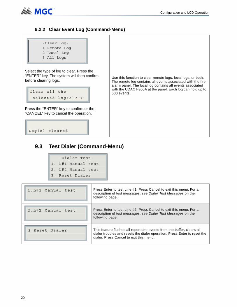
9.2.2 Clear Event Log (Command-Menu)
9.3 Test Dialer (Command-Menu)
Select the type of log to clear. Press the “ENTER” key. The system will then confirm before clearing logs.
Press the “ENTER” key to confirm or the “CANCEL” key to cancel the operation.
Use this function to clear remote logs, local logs, or both. The remote log contains all events associated with the fire alarm panel. The local log contains all events associated with the UDACT-300A at the panel. Each log can hold up to 500 events.
Press Enter to test Line #1. Press Cancel to exit this menu. For a description of test messages, see Dialer Test Messages on the following page.
Press Enter to test Line #2. Press Cancel to exit this menu. For a description of test messages, see Dialer Test Messages on the following page.
This feature flushes all reportable events from the buffer, clears all dialer troubles and resets the dialer operation. Press Enter to reset the dialer. Press Cancel to exit this menu.
-Clear Log-1 Remote Log2 Local Log3 All Logs
Clear all the
selected log(s)? Y
Log(s) cleared
-Dialer Test-
1. L#1 Manual test
2. L#2 Manual test
3. Reset Dialer
1.L#1 Manual test
2.L#2 Manual test
3 Reset Dialer.
20

Configuration and LCD Operation
9.3.1 Dialer Test Messages
The following messages will display during the test processes of Lines #1 and #2. The messages that will appear depend on the status of the dialer and the test results that are found.
The dialer is checking the line for voltage. This message automatically displays when Manual Test is selected.
No DC line voltage. The line is dead or no phone line is connected or the phone line operates at abnormal voltage.
The dialer is waiting for a dial tone.
This message may indicate a noisy telephone line.
The dial tone was detected and telephone number dialing is in process.
This message indicates that the dialer failed to send a DTMF tone.
Waiting for availability of the receiver. The receiver confirms the availability by sending an Ack tone.
Dialer failed to detect Ack tone. This message indicates that either the telephone number may be wrong or the receiver is not available.
Sending events to the receiver.
The dialer is waiting for the Kissoff tone. The Kissoff tone indicates that the receiver has received the event reports.
No Kissoff means dialer did not detect Kissoff tone.
Dialer idle now
No DC Volt
Waiting for Dialtone
Failed: No Dialtone
Dialing Receiver Now
No DTMF tone
Waiting for Acktone
Failed No Acktone
Reporting Event Now
Waiting for Kissoff
No Kissoff
21

Configuration and LCD Operation
9.4 Config Info (Command-Menu)
9.5 Version Info
Figure 9 Version Info
The first line shows the model number and panel type and the second line shows the software version number. The version of the software is read as Major.Minor.Revision. The display will remain for 10 seconds.
The line passed the test; everything is OK.
Press down arrow key to see more information.
Configuration type will show how the panel was configured. “Factory default” means the panel has not been configured, it is as it came from the factory. “Front Panel” means it was configured at the panel. “Serial Port” means the configuration was done from a computer through the serial port. “Modem” means the configuration was completed remotely through a modem.
If you upload a job configuration to the panel using the PC configuration utility, the job name will appear on this screen. The job name can be up to a maximum of 20 characters.
Press down arrow key for further info
If you upload a job configuration to the panel using the PC configuration utility, the technician’s name (ID) will appear on this screen. The technician ID can be up to a maximum of 10 characters.
Press down arrow key for further info
Configuration date and time will appear for all means of configuration, thus revealing date and time configuration was last changed.
This specifies the configuration tool version. It will display 0.0.0.0 if no PC configurator has been used.
Passed: Manual test
Configuration type:
Factory default
Job Name:
No job loaded
Technician ID:
Unknown
Cfg. Date and Time:
hh:mm day year:mm:dd
Cfg. Tool S/W Vers.:
Version:x.x.x.x
S/UDACT-300A
Version 1.0.1
22
Configuration and LCD Operation
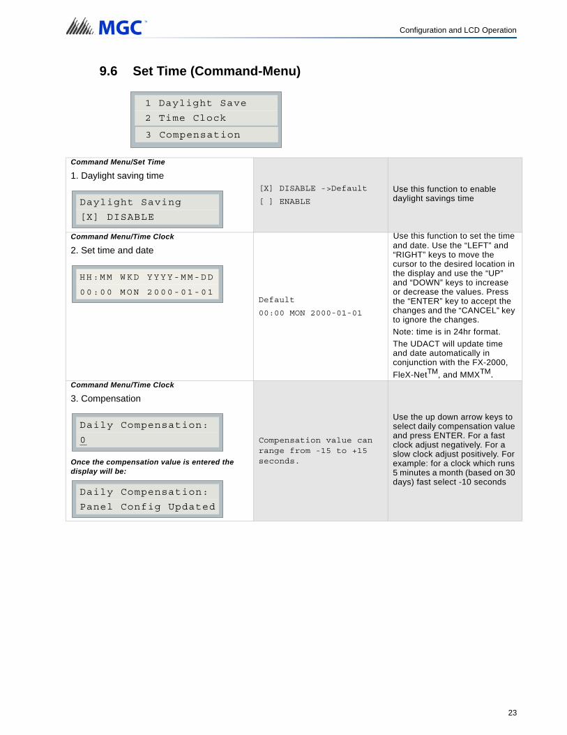
9.6 Set Time (Command-Menu)
Command Menu/Set Time
1. Daylight saving time[X] DISABLE ->Default
[ ] ENABLE
Use this function to enable daylight savings time
Command Menu/Time Clock
2. Set time and date
Default
00:00 MON 2000-01-01
Use this function to set the time and date. Use the “LEFT” and “RIGHT” keys to move the cursor to the desired location in the display and use the “UP” and “DOWN” keys to increase or decrease the values. Press the “ENTER” key to accept the changes and the “CANCEL” key to ignore the changes.
Note: time is in 24hr format.
The UDACT will update time and date automatically in conjunction with the FX-2000,
FleX-NetTM, and MMXTM.Command Menu/Time Clock
3. Compensation
Once the compensation value is entered the display will be:
Compensation value can range from -15 to +15 seconds.
Use the up down arrow keys to select daily compensation value and press ENTER. For a fast clock adjust negatively. For a slow clock adjust positively. For example: for a clock which runs 5 minutes a month (based on 30 days) fast select -10 seconds
1 Daylight Save
2 Time Clock
3 Compensation
Daylight Saving
[X] DISABLE
HH:MM WKD YYYY-MM-DD
00:00 MON 2000-01-01
Daily Compensation:
0
Daily Compensation:
Panel Config Updated
23
Configuration and LCD Operation
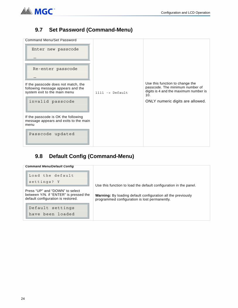
9.7 Set Password (Command-Menu)
9.8 Default Config (Command-Menu)
Command Menu/Set Password
If the passcode does not match, the following message appears and the system exit to the main menu
If the passcode is OK the following message appears and exits to the main menu
1111 -> Default
Use this function to change the passcode. The minimum number of digits is 4 and the maximum number is 10.
ONLY numeric digits are allowed.
Command Menu/Default Config
Press “UP” and “DOWN” to select between Y/N. if “ENTER” is pressed the default configuration is restored.
Use this function to load the default configuration in the panel.
Warning: By loading default configuration all the previously programmed configuration is lost permanently.
Enter new passcode
_
Re-enter passcode
_
invalid passcode
Passcode updated
Load the default
settings? Y
Default settings
have been loaded
24

Configuration and LCD Operation
9.9 Dialer Config (Command-Menu):
The following illustration shows the dialer configuration menu. Each item in this menu is described below in detail. Use the Up and Down keys to scroll through the menu and press the Enter key to make a selection. To exit from the menu, select the Exit menu option and then press either the Enter or Cancel key. Once a menu feature has been selected, use the Left and Right keys to change values or the numerical keys to enter account numbers.
9.9.1 Account Info Menu
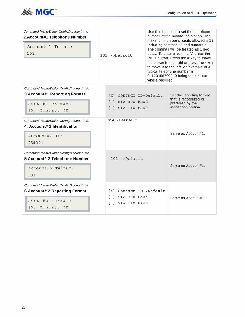
Command Menu/Dialer Config/Account Info
1.Account# 1 Identification
123456->Default
Use this function to set the Account ID for the monitoring station to which the dialer reports events. The maximum number of digits allowed is six. For contact ID, only the first four digits are used; the last two are truncated.
If you are using the Contact ID protocol, the allowed digits for the account ID are simple digits 0 to 9 and hexadecimal digits A to F. The SIA protocol only allows digits 0 to 9.
To enter hexadecimal digits, press the INFO button. The letter “A” will appear. To scroll through the rest of the letters, press INFO repeatedly. Press # key to move the cursor to the right or press * key to move it to the left.
- Dialer Config -1 Account Info2 Telephone Line3 Report Options4 Time Parameter5 Enable/Disable6 Ring Detection
1 Account#1 ID
2 Account#1 Tel
3 Accnt#1 Format
4 Account#2 ID
- Account Info -
5 Account#2 Tel
6 Accnt#2 Format
Account#1 ID:
123456
25
Configuration and LCD Operation
Command Menu/Dialer Config/Account Info
2.Account#1 Telephone Number
101 ->Default
Use this function to set the telephone number of the monitoring station. The maximum number of digits allowed is 19 including commas “,” and numerals. The commas will be treated as 1 sec delay. To enter a comma “,” press the INFO button. Press the # key to move the cursor to the right or press the * key to move it to the left. An example of a typical telephone number is 9,,1234567008, 9 being the dial out where required.
Command Menu/Dialer Config/Account Info
3.Account#1 Reporting Format [X] CONTACT ID-Default
[ ] SIA 300 Baud
[ ] SIA 110 Baud
Set the reporting format that is recognized or preferred by the monitoring station.
Command Menu/Dialer Config/Account Info
4. Account# 2 Identification
654321->Default
Same as Account#1.
Command Menu/Dialer Config/Account Info
5.Account# 2 Telephone Number 101 ->Default
Same as Account#1.
Command Menu/Dialer Config/Account Info
6.Account# 2 Reporting Format [X] Contact ID->Default
[ ] SIA 300 Baud
[ ] SIA 110 BaudSame as Account#1.
Account#1 Telnum:
101
ACCNT#1 Format:
[X] Contact ID
Account#2 ID:
654321
Account#2 Telnum:
101
ACCNT#2 Format:
[X] Contact ID
26
Configuration and LCD Operation
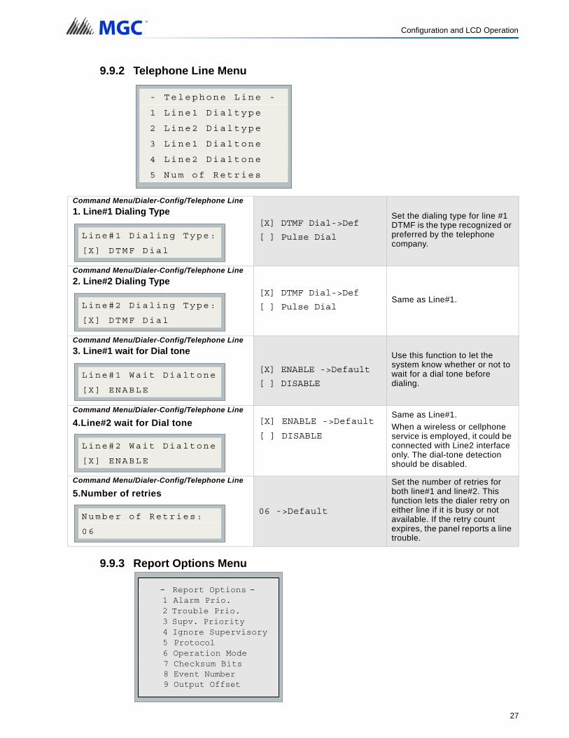
9.9.2 Telephone Line Menu
9.9.3 Report Options Menu
Command Menu/Dialer-Config/Telephone Line
1. Line#1 Dialing Type[X] DTMF Dial->Def
[ ] Pulse Dial
Set the dialing type for line #1 DTMF is the type recognized or preferred by the telephone company.
Command Menu/Dialer-Config/Telephone Line
2. Line#2 Dialing Type[X] DTMF Dial->Def
[ ] Pulse DialSame as Line#1.
Command Menu/Dialer-Config/Telephone Line
3. Line#1 wait for Dial tone
[X] ENABLE ->Default
[ ] DISABLE
Use this function to let the system know whether or not to wait for a dial tone before dialing.
Command Menu/Dialer-Config/Telephone Line
4.Line#2 wait for Dial tone [X] ENABLE ->Default
[ ] DISABLE
Same as Line#1.
When a wireless or cellphone service is employed, it could be connected with Line2 interface only. The dial-tone detection should be disabled.
Command Menu/Dialer-Config/Telephone Line
5.Number of retries
06 ->Default
Set the number of retries for both line#1 and line#2. This function lets the dialer retry on either line if it is busy or not available. If the retry count expires, the panel reports a line trouble.
1 Line1 Dialtype
2 Line2 Dialtype
3 Line1 Dialtone
4 Line2 Dialtone
- Telephone Line -
5 Num of Retries
Line#1 Dialing Type:
[X] DTMF Dial
Line#2 Dialing Type:
[X] DTMF Dial
Line#1 Wait Dialtone
[X] ENABLE
Line#2 Wait Dialtone
[X] ENABLE
Number of Retries:
06
1 Alarm Prio .
2 Trouble Prio .
3 Supv. Priority
4 Aux Dis Report
- -
5 Fire Panel
6 Operation Mode
7
- Report Options -1 Alarm Prio.2 Trouble Prio.3 Supv. Priority4 Ignore Supervisory5 Protocol6 Operation Mode7 Checksum Bits8 Event Number9 Output Offset
27
Configuration and LCD Operation
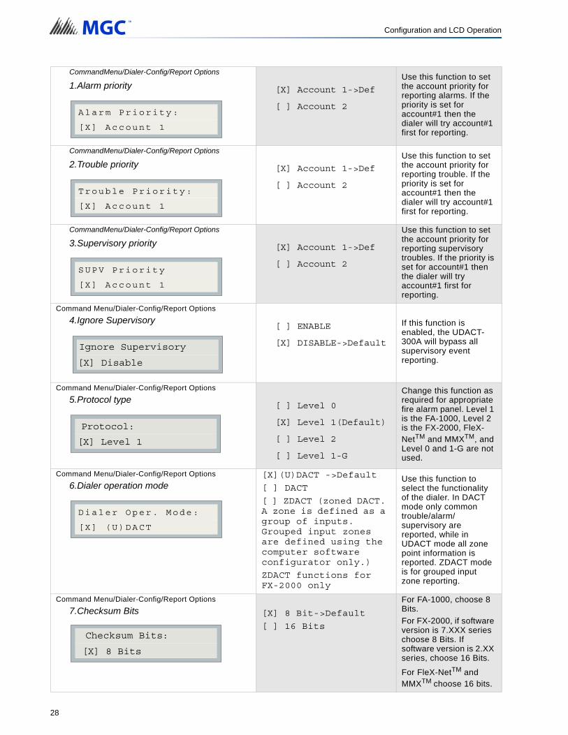
CommandMenu/Dialer-Config/Report Options
1.Alarm priority [X] Account 1->Def
[ ] Account 2
Use this function to set the account priority for reporting alarms. If the priority is set for account#1 then the dialer will try account#1 first for reporting.
CommandMenu/Dialer-Config/Report Options
2.Trouble priority [X] Account 1->Def
[ ] Account 2
Use this function to set the account priority for reporting trouble. If the priority is set for account#1 then the dialer will try account#1 first for reporting.
CommandMenu/Dialer-Config/Report Options
3.Supervisory priority [X] Account 1->Def
[ ] Account 2
Use this function to set the account priority for reporting supervisory troubles. If the priority is set for account#1 then the dialer will try account#1 first for reporting.
Command Menu/Dialer-Config/Report Options
4.Ignore Supervisory
[ ] ENABLE
[X] DISABLE->Default
If this function is enabled, the UDACT-300A will bypass all supervisory event reporting.
Command Menu/Dialer-Config/Report Options
5.Protocol type[ ] Level 0
[X] Level 1(Default)
[ ] Level 2
[ ] Level 1-G
Change this function as required for appropriate fire alarm panel. Level 1 is the FA-1000, Level 2 is the FX-2000, FleX-NetTM and MMXTM, and Level 0 and 1-G are not used.
Command Menu/Dialer-Config/Report Options
6.Dialer operation mode[X](U)DACT ->Default
[ ] DACT
[ ] ZDACT (zoned DACT. A zone is defined as a group of inputs. Grouped input zones are defined using the computer software configurator only.)
ZDACT functions for FX-2000 only
Use this function to select the functionality of the dialer. In DACT mode only common trouble/alarm/supervisory are reported, while in UDACT mode all zone point information is reported. ZDACT mode is for grouped input zone reporting.
Command Menu/Dialer-Config/Report Options
7.Checksum Bits [X] 8 Bit->Default
[ ] 16 Bits
For FA-1000, choose 8 Bits.
For FX-2000, if software version is 7.XXX series choose 8 Bits. If software version is 2.XX series, choose 16 Bits.
For FleX-NetTM and MMXTM choose 16 bits.
Alarm Priority:
[X] Account 1
Trouble Priority:
[X] Account 1
SUPV Priority
[X] Account 1
Ignore Supervisory
[X] Disable
Protocol:
[X] Level 1
Dialer Oper. Mode:
[X] (U)DACT
Checksum Bits:
[X] 8 Bits
28

Configuration and LCD Operation
Command Menu/Dialer-Config/Report Options
8.Event Number[X] Loop & Address
[ ] Ckt No
Used to specify UDACT reporting information for FX-2000 non grouped inputs.
Loop & Address: Five digits will be displayed for Loop and Address with first two digits (from the left) representing loop number and the next 3 digits representing the device address.
Circuit Number If circuit number is selected the UDACT will report only the input/output circuit number, five digits.
Note: If inputs are grouped, only the group number will be reported by the dialer regardless of Event Number Format selection.
Command Menu/Dialer-Config/Report Options
9.Output Offset
0 ->Default
Can be set from 1 to 9999
Used to offset the number of the outputs. i.e. if 1000 is chosen, then the first output will have address 1001, output 2 will be 1002, etc. The offset feature is available only if the event format (shown above) of circuit number is chosen. This offset function is available for FX-2000, FleX-NetTM, and MMXTM only.
Note: For FleX-NetTM and MMXTM, the dialer reports circuits which are grouped. If the
FleX-NetTM and/or MMXTM circuits are not grouped at the panel, the dialer does not report.
Event Number Format:
[X] Loop & Address
Output Number Offset?
_ _ _ _
i
29

Configuration and LCD Operation
9.9.4 New ZDACT Feature for FX-2000
Using the Dialer Configuration Utility only, input circuits (of the FX-2000 only) can be grouped so that the UDACT will report any individual input event as a group event. If a device is not in the group, the dialer will report the event directly. Use the File menu to open an existing file or create a new one.
Double click on the System menu (right-hand side of the screen) to select the type of dialer.
30

Configuration and LCD Operation
Select the Dialer Menu from the left-side of the screen and the Dialer Configuration information will appear on the right-hand as shown below.
9.9.5 Select the Dialer Mode
Double click on the Dialer Configuration information shown on the right and the following screen will appear.
31
Configuration and LCD Operation
Cursor down to the Dialer box, Mode line and select ZDACT. Do not forget to select Communications Protocol Level 2 and Checksum 16 bit in the Attached Fire Alarm box, then select OK and enter.
9.9.6 Grouping Inputs
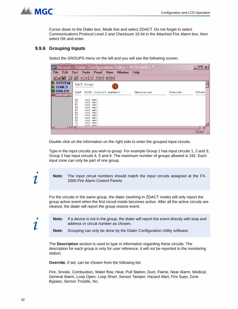
Select the GROUPS menu on the left and you will see the following screen.
Double click on the information on the right side to enter the grouped input circuits.
Type in the input circuits you wish to group. For example Group 1 has input circuits 1, 2 and 3; Group 2 has input circuits 4, 5 and 6. The maximum number of groups allowed is 192. Each input zone can only be part of one group.
For the circuits in the same group, the dialer (working in ZDACT mode) will only report the group active event when the first circuit inside becomes active. After all the active circuits are cleared, the dialer will report the group restore event.
The Description section is used to type in information regarding these circuits. The description for each group is only for user reference, it will not be reported to the monitoring station.
Override, if set, can be chosen from the following list:
Fire, Smoke, Combustion, Water flow, Heat, Pull Station, Duct, Flame, Near Alarm, Medical, General Alarm, Loop Open, Loop Short, Sensor Tamper, Hazard Alert, Fire Supv, Zone Bypass, Sensor Trouble, No.
Note: The input circuit numbers should match the input circuits assigned at the FX-2000 Fire Alarm Control Panels.
Note: If a device is not in the group, the dialer will report the event directly with loop andaddress or circuit number as chosen.
Note: Grouping can only be done by the Dialer Configuration Utility software.
i
i
32
Configuration and LCD Operation
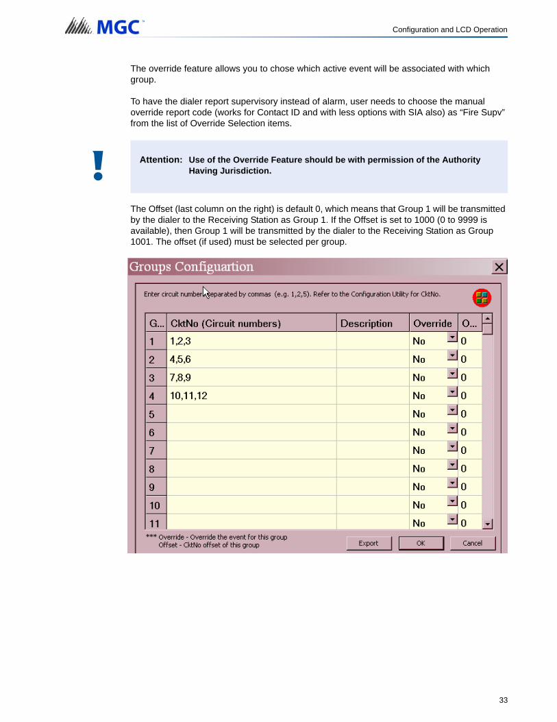
The override feature allows you to chose which active event will be associated with which group.
To have the dialer report supervisory instead of alarm, user needs to choose the manual override report code (works for Contact ID and with less options with SIA also) as “Fire Supv” from the list of Override Selection items.
The Offset (last column on the right) is default 0, which means that Group 1 will be transmitted by the dialer to the Receiving Station as Group 1. If the Offset is set to 1000 (0 to 9999 is available), then Group 1 will be transmitted by the dialer to the Receiving Station as Group 1001. The offset (if used) must be selected per group.
Attention: Use of the Override Feature should be with permission of the Authority Having Jurisdiction.!
33
Configuration and LCD Operation
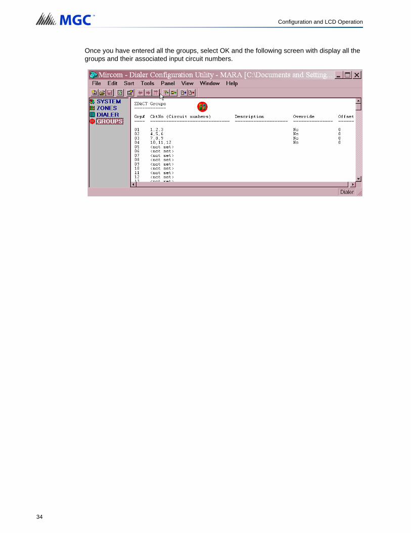
Once you have entered all the groups, select OK and the following screen with display all the groups and their associated input circuit numbers.
34

Configuration and LCD Operation
9.10 Time Parameter Menu
Command Menu/Dialer-Config/Time Parameter
1.AC Loss delay0 ->Default
Use this function to delay the reporting of AC loss trouble on the dialer for the programmed time period. Selection is from 0 to 20 hours.
Command Menu/Dialer-Config/Time Parameter
2.Cellular report date 0 ->DefaultThis sets the day of the month that Line 2 will be tested. Valid numbers are 0 to 31. On the report date selected only, Line 2 will be tested once if the Auto-Test Time is between 00:01 and 12:00 or twice if the Auto-Test Time is between 12:00 and 23:59
If this is set to 0, Line 2 will be tested once or twice every other day as per time selected in the Auto-Test Time
Command Menu/Dialer-Config/Time Parameter
3.Auto test time
00:30 ->Default
Use this function to set the time for auto test. When this test is performed the test report is sent to the monitoring station. The time is in 24hr format (using the CFG-300), which means 00:30 is 30 minutes after midnight.
The test will be preformed once a day, unless the time is set between 12:00 and 23:59, then auto test will be performed twice a day. Both lines will be tested daily if the Cellular Report Date is set to 0. If the Cellular Report Date is anything other than 0, line 1 will be tested once or twice (depending on the Auto-Test Time selected) a day and line 2 will be tested once or twice (depending on the Auto-Test Time selected) on the Cellular Report Date.
Please avoid the following Test Times: 00:00, 01:55, 02:00 and 03:00
1 AC-Loss Delay
2 Cellphone Date
3 Auto-Test Time
-Time Parameter-
AC-Loss Delay(Hrs)
0
Cellular Report Date
0
Auto-Test Time
00:30
35
Configuration and LCD Operation
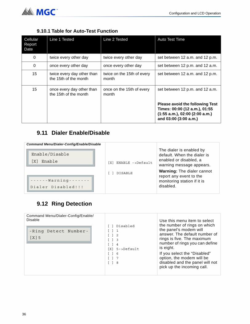
9.10.1 Table for Auto-Test Function
9.11 Dialer Enable/Disable
9.12 Ring Detection
CellularReportDate
Line 1 Tested Line 2 Tested Auto Test Time
0 twice every other day twice every other day set between 12 a.m. and 12 p.m.
0 once every other day once every other day set between 12 p.m. and 12 a.m.
15 twice every day other than the 15th of the month
twice on the 15th of every month
set between 12 a.m. and 12 p.m.
15 once every day other than the 15th of the month
once on the 15th of every month
set between 12 p.m. and 12 a.m.
Please avoid the following Test Times: 00:00 (12 a.m.), 01:55 (1:55 a.m.), 02:00 (2:00 a.m.) and 03:00 (3:00 a.m.)
Command Menu/Dialer-Config/Enable/Disable
[X] ENABLE ->Default
[ ] DISABLE
The dialer is enabled by default. When the dialer is enabled or disabled, a warning message appears.
Warning: The dialer cannot report any event to the monitoring station if it is disabled.
Command Menu/Dialer-Config/Enable/Disable
[ ] Disabled[ ] 1[ ] 2[ ] 3[ ] 4[X] 5->Default[ ] 6[ ] 7[ ] 8
Use this menu item to select the number of rings on which the panel’s modem will answer. The default number of rings is five. The maximum number of rings you can define is eight.
If you select the “Disabled” option, the modem will be disabled and the panel will not pick up the incoming call.
Enable/Disable
[X] Enable
------Warning-------
Dialer Disabled!!!
[X]5
-Ring Detect Number-
36

Configuration and LCD Operation
C
P
P
P
P
F
R
R
P
PN
M
C
Z
Z
S
S
C
C
F
F
Z
Z
Z
Z
S
S
9.13 Exit (Command-Menu)
Pressing “ENTER” after selecting “Exit from the main menu will return the UDACT-300A to normal.
ADEMCO CONTACT-ID
UDACT-300A Internal Events:
UDACT-300A External Events:
ontact-ID Event Description Event Family Qualifier Code Group # Contact #
hone Line #1 trouble detected Trouble New event 1 351 00 000
hone Line #2 trouble detected Trouble New event 1 352 00 000
hone Line #1 trouble restored Trouble Restore 3 351 00 000
hone Line #2 trouble restored Trouble Restore 3 352 00 000
ailure to report to an Account Trouble New event 1 354 Acct # Acct #
eport to an Account successful Trouble Restore 3 354 Acct # Acct #
S-485 Communication Trouble Trouble New event 1 350 00 485
eriodic (24 hr) Test Event (NORMAL) Test New event 1 602 00 000
eriodic (24 hr) Test Event (OFF ORMAL)
Test New event 1 608 00 000
anually initiated dialer test Test New event 1 601 00 000
ontact-ID Event Description Event Family Qualifier Code Group # Contact #
one Fire Alarm Alarm New event 1 110 00 NNN
one Fire Alarm restored Alarm Restore 3 110 00 NNN
moke Alarm Alarm New event 1 111 00 NNN
moke Alarm restored Alarm Restore 3 111 00 NNN
ombustible Alarm Alarm New event 1 112 00 NNN
ombustible Alarm restored Alarm Restore 3 112 00 NNN
ire Drill Trouble New event 1 604 00 NNN
ire Drill restore Trouble Restore 3 604 00 NNN
one Trouble detected Trouble New event 1 300 00 NNN
one Trouble restored Trouble Restore 3 300 00 NNN
one Supervisory condition Supervisory New event 1 200 00 NNN
one Supervisory restored Supervisory Restore 3 200 00 NNN
ystem Trouble Trouble New event 1 300 00 NNN
ystem Trouble restore Trouble Restore 3 300 00 NNN
37

Configuration and LCD Operation
S
S
S
S
W
W
H
H
P
P
D
D
F
F
M
M
S
S
H
H
In
In
B
B
B
B
B
B
B
B
B
B
B
C
ensor Bypass Trouble New event 1 570 00 NNN
ensor Bypass restore Trouble Restore 3 570 00 NNN
ensor Trouble Trouble New event 1 380 00 NNN
ensor Trouble restore Trouble Restore 3 380 00 NNN
aterflow Alarm New event 1 113 00 NNN
aterflow restored Alarm Restore 3 113 00 NNN
eat Alarm Alarm New event 1 114 00 NNN
eat Alarm restored Alarm Restore 3 114 00 NNN
ull Station Alarm Alarm New event 1 115 00 NNN
ull Station Alarm restore Alarm Restore 3 115 00 NNN
uct Alarm Alarm New event 1 116 00 NNN
uct Alarm restore Alarm Restore 3 116 00 NNN
lame Alarm Alarm New event 1 117 00 NNN
lame Alarm restore Alarm Restore 3 117 00 NNN
edical Alarm Alarm New event 1 100 00 NNN
edical Alarm restore Alarm Restore 3 100 00 NNN
ensor Tamper Alarm Alarm New event 1 144 00 NNN
ensor Tamper Alarm restore Alarm Restore 3 144 00 NNN
azard Alert Alarm Alarm New event 1 150 00 NNN
azard Alert Alarm restore Alarm Restore 3 150 00 NNN
dicating Zone Trouble Trouble New event 1 320 00 NNN
dicating Zone Trouble restored Trouble Restore 3 320 00 NNN
ell Circuit 1 Trouble Trouble New event 1 321 00 NNN
ell Circuit 1 Trouble restore Trouble Restore 3 321 00 NNN
ell Circuit 2 Trouble Trouble New event 1 322 00 NNN
ell Circuit 2 Trouble restore Trouble Restore 3 322 00 NNN
ell Circuit 3 Trouble Trouble New event 1 326 00 NNN
ell Circuit 3 Trouble restore Trouble Restore 3 326 00 NNN
ell Circuit 4 Trouble Trouble New event 1 327 00 NNN
ell Circuit 4 Trouble restore Trouble Restore 3 327 00 NNN
ell Bypass Trouble Trouble New event 1 520 00 NNN
ell Bypass Trouble restore Trouble Restore 3 520 00 NNN
ell Bypass 1 Trouble Trouble New event 1 521 00 NNN
ontact-ID Event Description Event Family Qualifier Code Group # Contact #
38

Configuration and LCD Operation
B
B
B
B
B
B
B
S
S
G
G
L
S
P
T
R
R
P
P
P
P
L
L
L
A
A
B
B
G
G
C
NNN-Refers to Sensor number for zone causing event.
SECURITY INDUSTRIES ASSOC. SIA-DCS
ell Bypass 1 Trouble restore Trouble Restore 3 521 00 NNN
ell Bypass 2 Trouble Trouble New event 1 522 00 NNN
ell Bypass 2 Trouble restore Trouble Restore 3 522 00 NNN
ell Bypass 3 Trouble Trouble New event 1 526 00 NNN
ell Bypass 3 Trouble restore Trouble Restore 3 526 00 NNN
ell Bypass 4 Trouble Trouble New event 1 527 00 NNN
ell Bypass 4 Trouble restore Trouble Restore 3 527 00 NNN
ystem Down Trouble New event 1 308 00 NNN
ystem Down restore Trouble Restore 3 308 00 NNN
eneral Alarm Alarm New event 1 140 00 NNN
eneral Alarm restored Alarm Restore 3 140 00 NNN
oop Open Trouble Trouble New event 1 141 00 NNN
ystem Reset Trouble New event 1 305 00 000
rogram Change Trouble New event 1 306 00 000
ime Change Trouble New event 1 625 00 000
AM Checksum Trouble New event 1 303 00 000
OM Checksum Trouble New event 1 304 00 000
eripheral Trouble Trouble New event 1 330 00 000
eripheral Trouble restore Trouble Restore 3 330 00 000
rinter Error Trouble New event 1 336 00 000
rinter Error restore Trouble Restore 3 336 00 000
oop Open Trouble restore Trouble Restore 3 141 00 NNN
oop Short Trouble Trouble New event 1 142 00 NNN
oop Open Trouble restore Trouble Restore 3 142 00 NNN
C power lost Trouble New event 1 301 00 000
C power restored Trouble Restore 3 301 00 000
attery Low Trouble New event 1 302 00 000
attery Low restored Trouble Restore 3 302 00 000
round Fault Trouble New event 1 310 00 000
round Fault restored Trouble Restore 3 310 00 000
ontact-ID Event Description Event Family Qualifier Code Group # Contact #
39

Configuration and LCD Operation
C
P
P
P
P
F
R
R
P
P
M
UDACT-300A Internal Events:
UDACT-300A External Events:
ontact-ID Event Description Event Family Qualifier SIA Event Code
Parameter
hone Line #1 trouble detected Trouble New event LT 001
hone Line #2 trouble detected Trouble New event LT 002
hone Line #1 trouble restored Trouble Restore LR 001
hone Line #2 trouble restored Trouble Restore LR 002
ailure to report to an Account Trouble New event YC Acct #
eport to an Account successful Trouble Restore YK Acct #
S485 Communication Trouble Trouble New event YS 485
eriodic (24 hr) Test Event (Normal) Test New event RP 000
eriodic (24 hr) Test Event (Off-normal) Test New event RY 000
anually initiated dialer test Test New event RX 000
Event Description Event Family Qualifier SIA EventCode
Parameter
Zone Fire Alarm Alarm New event FA NNN
Zone Fire Alarm restored Alarm Restore FH NNN
Zone (Sensor) Trouble detected Trouble New event FT NNN
Zone (Sensor) Trouble restored Trouble Restore FJ NNN
Sensor Bypass Trouble New event FB NNN
Sensor Bypass restored Trouble Restore FU NNN
Zone Supervisory condition Supervisory New event FS NNN
Zone Supervisory restored Supervisory Restore FR NNN
Sensor Bypass Trouble New event FB NNN
Sensor Bypass restored Trouble Restore FU NNN
Waterflow alarm Alarm New event WA NNN
Waterflow alarm restored Alarm Restore WH NNN
Heat alarm Alarm New event KA NNN
Heat alarm restored Alarm Restore KH NNN
General Alarm Alarm New event QA NNN
General Alarm restored Alarm Restore QH NNN
Near Alarm Alarm New event 00 NNN
Near Alarm Alarm Restore 00 NNN
40
Configuration and LCD Operation
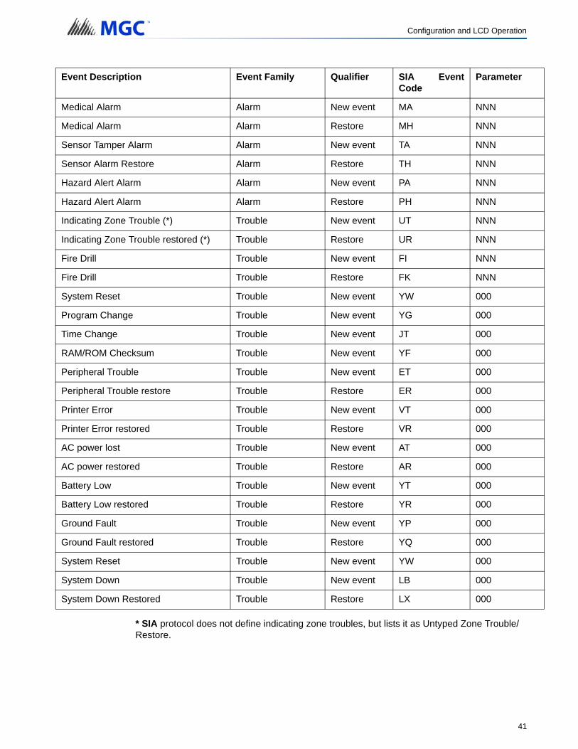
* SIA protocol does not define indicating zone troubles, but lists it as Untyped Zone Trouble/Restore.
Medical Alarm Alarm New event MA NNN
Medical Alarm Alarm Restore MH NNN
Sensor Tamper Alarm Alarm New event TA NNN
Sensor Alarm Restore Alarm Restore TH NNN
Hazard Alert Alarm Alarm New event PA NNN
Hazard Alert Alarm Alarm Restore PH NNN
Indicating Zone Trouble (*) Trouble New event UT NNN
Indicating Zone Trouble restored (*) Trouble Restore UR NNN
Fire Drill Trouble New event FI NNN
Fire Drill Trouble Restore FK NNN
System Reset Trouble New event YW 000
Program Change Trouble New event YG 000
Time Change Trouble New event JT 000
RAM/ROM Checksum Trouble New event YF 000
Peripheral Trouble Trouble New event ET 000
Peripheral Trouble restore Trouble Restore ER 000
Printer Error Trouble New event VT 000
Printer Error restored Trouble Restore VR 000
AC power lost Trouble New event AT 000
AC power restored Trouble Restore AR 000
Battery Low Trouble New event YT 000
Battery Low restored Trouble Restore YR 000
Ground Fault Trouble New event YP 000
Ground Fault restored Trouble Restore YQ 000
System Reset Trouble New event YW 000
System Down Trouble New event LB 000
System Down Restored Trouble Restore LX 000
Event Description Event Family Qualifier SIA EventCode
Parameter
41
10.0 Compatible Fire Alarm Control PanelsUDACT-300A: Compatible with FA-1000 Series, FX-2000 Series, FleX-Net TM and MMXTM Fire Alarm Control Panels
42

11.0 Connecting to a 3G4010/CF Interface Device
11.1 Connecting to a 3G4010 Interface Device for Canada
A typical connection is shown in Figure 10. The PCS-100 Passive Communications Interface Board (sold separately) is required.
For information on Compatible Receivers see “Compatible Receivers” on page 45.
Figure 10 Connecting an FACP to a 3G4010 Interface Device in Canada
Note: The DSC interface device 3G4010 is required if the installation requires ULC S559 certification. The DSC interface device 3G4010CF is required if the installation requires UL864 9th edition certification.
ALARM RELAY
SPV RELAY
TRBL RELAY
TelephoneLine A
Connection
DC IN
EOL
To GSM/GPRS
Typical Installation in Canada
Line 2Line 1
PCS-100
POW
ER24V
G
ND P GM
4 GN
D 1 4V
NC
CO
M N
O
TBL RELA
Y
JW1
PGM4
AUX SUPPLY +
-
+ -
Internet
Computer
Printer SUR-GARD SYSTEM IV
Internal IP: X.X.X.XExternal IP: X.X.X.X
SG-SystemsConsole 2.1
Default Gateway: X.X.X.XSub-Net Mask:X.X.X.XPort #: YYYY (UDP)
NOC
NOC
NOC
COM
Z3
Z2
Z1 T1 R1
(-)
(+)
Conventional input configured as 3G4010 radio trouble
FACP
UDACT-300A
3G4010 TRBL
Addressable module configured as 3G4010 radio trouble
3G4010
Option 1 (dashed line): Conventional input configured as 3G4010 radio trouble
Option 2 (dotted line): Monitor module input
Legend
C.O. C.O.
FACP - 3G4010 Connection - Typical Diagram
Router
- All units must be installed in the same room- All extended wiring must be in metallic conduit- Wiring between FACP and 3G4010: 18 m max.
Contact DSC to reprogram the zone inputs to match the FACP as shown in this diagram
-
i
43

Connecting to a 3G4010/CF Interface Device
11.2 Connecting to a 3G4010CF Interface Device outside Canada
For information on Compatible Receivers see “Compatible Receivers” on page 45.
A typical connection is shown in Figure 11. The 3G4010CF is powered separately from the PCS-100 and requires 2 DSC RM-2 relays (sold separately). The PCS-100 Passive Communications Interface Board (sold separately) is also required.
Figure 11 Connecting an FACP to a 3G4010CF Interface Device outside Canada
Note: The DSC interface device 3G4010 is required if the installation requires ULC S559 certification. The DSC interface device 3G4010CF is required if the installation requires UL864 9th edition certification.
TelephoneLine A
Connection
EOL
Line 2C.O.
Line 1 C.O.
PCS-100
POW
ER24V
G
ND P GM
4 GN
D 1 4V
NC
CO
M N
O
TBL RELA
Y
JW1AUX SUPPLY +
-
+ -
To GSM/GPRS
Internet
Computer
Printer SUR-GARD SYSTEM IV
Internal IP: X.X.X.XExternal IP: X.X.X.X
SG-SystemsConsole 2.1
Default Gateway: X.X.X.XSub-Net Mask:X.X.X.XPort #: YYYY (UDP)
Router
Conventional input configured as 3G4010CF radio trouble
FACP
UDACT-300A
3G4010CF TRBL
Option 1 (dashed line): Conventional input
Legend
ALARM RELAY
SPV RELAY
TRBL RELAY
NOC
NOC
NOC
+-
FACP - 3G4010CF Connection - Typical Diagram
Typical Installation outside Canada
- All units must be installed in the same room- All extended wiring must be in metallic conduit- Wiring between FACP and 3G4010CF: 20 feet max.- Contact DSC to reprogram the zone inputs to match the FACP as shown in this diagram- Use 2 DSC RM-2 Relays (sold separately) to supervise both AC failure trouble and low battery trouble- Install the DSC RM-2 Relays inside the 3G4010CF enclosure, above the PS4086
Option 2 (dotted line): Addressable module
3G4010CF TRBL
PGM4
COM
Z3
Z2
Z1
T1 R1
NC COM NO
DSC RM-2 Relay
EOL
-
PS4086
Transformer Battery
DC IN
+12V COMAC IN
+
ACT LBT
NC COM NO
DSC RM-2 Relay
EOL
-+
BAT+ BAT-
3G4010CF
3G4010CF TRBL
+-
+-
Addressable module configured as AC failure trouble
Addressable module configured as low
battery trouble
Addressable module configured as 3G4010CF radio trouble
Conventional input configured as AC failure trouble
Conventional input configured as low battery trouble
i
44
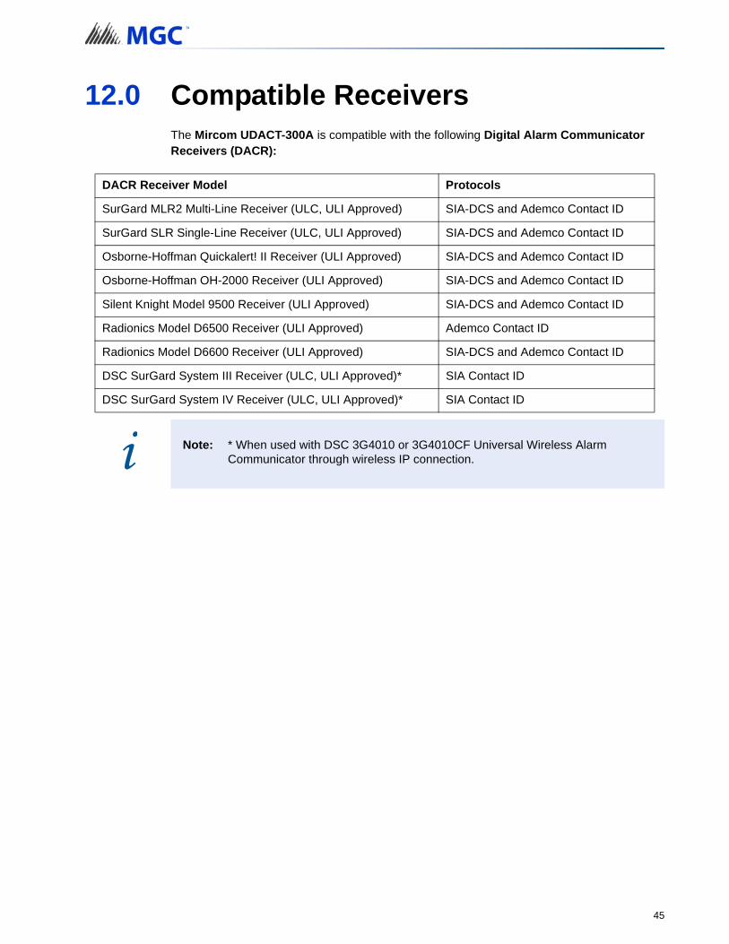
12.0 Compatible ReceiversThe Mircom UDACT-300A is compatible with the following Digital Alarm Communicator Receivers (DACR):
DACR Receiver Model Protocols
SurGard MLR2 Multi-Line Receiver (ULC, ULI Approved) SIA-DCS and Ademco Contact ID
SurGard SLR Single-Line Receiver (ULC, ULI Approved) SIA-DCS and Ademco Contact ID
Osborne-Hoffman Quickalert! II Receiver (ULI Approved) SIA-DCS and Ademco Contact ID
Osborne-Hoffman OH-2000 Receiver (ULI Approved) SIA-DCS and Ademco Contact ID
Silent Knight Model 9500 Receiver (ULI Approved) SIA-DCS and Ademco Contact ID
Radionics Model D6500 Receiver (ULI Approved) Ademco Contact ID
Radionics Model D6600 Receiver (ULI Approved) SIA-DCS and Ademco Contact ID
DSC SurGard System III Receiver (ULC, ULI Approved)* SIA Contact ID
DSC SurGard System IV Receiver (ULC, ULI Approved)* SIA Contact ID
Note: * When used with DSC 3G4010 or 3G4010CF Universal Wireless Alarm Communicator through wireless IP connection.i
45

13.0 SpecificationsAll Circuits are Power Limited
UDACT-300A Digital Communicator
• Connects to two Telephone Lines and performs line supervision.
• Connects to a Mircom FACP via a ribbon cable. This connection provides DC power, RS-485 Data Link, common relay connections and all other signaling between the Communicator and the FACP.
• Transmits Zoned Alarm, Supervisory, and Trouble status to a Central Monitoring Station, using either Ademco Contact ID or SIA DCS Protocols.
• User configurable locally or remotely. Configuration is passcode protected.
• Current Consumption: Standby: 40 mA Alarm: 60 mA
14.0 Battery CalculationsThe UDACT-300A Battery Calculations are performed as part of the calculations for the Fire Alarm Control Panel it will be used in. See the appropriate Mircom Installation and Operation Manual.
46

15.0 Warranty and Warning Information
WARNING!Please read this document CAREFULLY, as it contains important warnings, life-safety, and practical information about all products manufactured by the Mircom Group of Companies, including Mircom and Secutron branded products, which shall include without limitation all fire alarm, nurse call, building automation and access control and card access products (hereinafter individually or collectively, as applicable, referred to as “Mircom System”).
NOTE TO ALL READERS:
1. Nature of Warnings. The within warnings are communicated to the reader out of an abundance of caution and create no legal obligation for Mircom Group of Companies, whatsoever. Without limiting the generality of the foregoing, this document shall NOT be construed as in any way altering the rights and obligations of the parties, governed by the legal documents that apply in any given circumstance.
2. Application. The warnings contained in this document apply to all Mircom System and shall be read in conjunction with:
a. the product manual for the specific Mircom System that applies in given circumstances;
b. legal documents that apply to the purchase and sale of a Mircom System, which may include the company’s standard terms and conditions and warranty statements;
c. other information about the Mircom System or the parties’ rights and obligations as may be application to a given circumstance.
3. Security and Insurance. Regardless of its capabilities, no Mircom System is a substitute for property or life insurance. Nor is the system a substitute for property owners, renters, or other occupants to act prudently to prevent or minimize the harmful effects of an emergency situation. Building automation systems produced by the Mircom Group of Companies are not to be used as a fire, alarm, or life-safety system.
NOTE TO INSTALLERS:
All Mircom Systems have been carefully designed to be as effective as possible. However, there are circumstances where they may not provide protection. Some reasons for system failure include the following. As the only individual in contact with system users, please bring each item in this warning to the attention of the users of this Mircom System. Failure to properly inform system end-users of the circumstances in which the system might fail may result in over-reliance upon the system. As a result, it is imperative that you properly inform each customer for whom you install the system of the possible forms of failure:
4. Inadequate Installation. All Mircom Systems must be installed in accordance with all the applicable codes and standards in order to provide adequate protection. National standards require an inspection and approval to be conducted by the local authority having jurisdiction following the initial installation of the system and following any changes to the system. Such inspections ensure installation has been carried out properly.
5. Inadequate Testing. Most problems that would prevent an alarm a Mircom System from operating as intended can be discovered by regular testing and maintenance. The complete system should be tested by the local authority having jurisdiction immediately after a fire, storm, earthquake, accident, or any kind of construction activity inside or outside the premises.
47
Warranty and Warning Information
The testing should include all sensing devices, keypads, consoles, alarm indicating devices and any other operational devices that are part of the system.
NOTE TO USERS:
All Mircom Systems have been carefully designed to be as effective as possible. However, there are circumstances where they may not provide protection. Some reasons for system failure include the following. The end user can minimize the occurrence of any of the following by proper training, testing and maintenance of the Mircom Systems:
6. Inadequate Testing and Maintenance. It is imperative that the systems be periodically tested and subjected to preventative maintenance. Best practices and local authority having jurisdiction determine the frequency and type of testing that is required at a minimum. Mircom System may not function properly, and the occurrence of other system failures identified below may not be minimized, if the periodic testing and maintenance of Mircom Systems is not completed with diligence and as required.
7. Improper Operation. It is important that all system users be trained in the correct operation of the alarm system and that they know how to respond when the system indicates an alarm. A Mircom System may not function as intended during an emergency situation where the user is unable to operate a panic or emergency switch by reason of permanent or temporary physical disability, inability to reach the device in time, unfamiliarity with the correct operation, or related circumstances.
8. Insufficient Time. There may be circumstances when a Mircom System will operate as intended, yet the occupants will not be protected from the emergency due to their inability to respond to the warnings in a timely manner. If the system is monitored, the response may not occur in time enough to protect the occupants or their belongings.
9. Carelessness or Safety Hazards. Moreover, smoke detectors may not provide timely warning of fires caused by carelessness or safety hazards such as smoking in bed, violent explosions, escaping gas, improper storage of flammable materials, overloaded electrical circuits or children playing with matches or arson.
10. Power Failure. Some Mircom System components require adequate electrical power supply to operate. Examples include: smoke detectors, beacons, HVAC, and lighting controllers. If a device operates only by AC power, any interruption, however brief, will render that device inoperative while it does not have power. Power interruptions of any length are often accompanied by voltage fluctuations which may damage Mircom Systems or other electronic equipment. After a power interruption has occurred, immediately conduct a complete system test to ensure that the system operates as intended.
11. Battery Failure. If the Mircom System or any device connected to the system operates from batteries it is possible for the batteries to fail. Even if the batteries have not failed, they must be fully charged, in good condition, and installed correctly. Some Mircom Systems use replaceable batteries, which have a limited life-span. The expected battery life is variable and in part dependent on the device environment, usage and type. Ambient conditions such as high humidity, high or low temperatures, or large temperature fluctuations may reduce the expected battery life. Moreover, some Mircom Systems do not have a battery monitor that would alert the user in the event that the battery is nearing its end of life. Regular testing and replacements are vital for ensuring that the batteries function as expected, whether or not a device has a low-battery monitor.
12. Physical Obstructions. Motion sensors that are part of a Mircom System must be kept clear of any obstacles which impede the sensors’ ability to detect movement. Signals being communicated by a Mircom System may not reach the receiver if an item (such as metal, water, or concrete) is placed on or near the radio path. Deliberate jamming or other inadvertent radio signal interference can also negatively affect system operation.
48
Warranty and Warning Information
13. Wireless Devices Placement Proximity. Moreover all wireless devices must be a minimum and maximum distance away from large metal objects, such as refrigerators. You are required to consult the specific Mircom System manual and application guide for any maximum distances required between devices and suggested placement of wireless devices for optimal functioning.
14. Failure to Trigger Sensors. Moreover, Mircom Systems may fail to operate as intended if motion, heat, or smoke sensors are not triggered.
a. Sensors in a fire system may fail to be triggered when the fire is in a chimney, walls, roof, or on the other side of closed doors. Smoke and heat detectors may not detect smoke or heat from fires on another level of the residence or building. In this situation the control panel may not alert occupants of a fire.
b. Sensors in a nurse call system may fail to be triggered when movement is occurring outside of the motion sensors’ range. For example, if movement is occurring on the other side of closed doors or on another level of the residence or building the motion detector may not be triggered. In this situation the central controller may not register an alarm signal.
15. Interference with Audible Notification Appliances. Audible notification appliances may be interfered with by other noise sources such as stereos, radios, televisions, air conditioners, appliances, or passing traffic. Audible notification appliances, however loud, may not be heard by a hearing-impaired person.
16. Other Impairments. Alarm notification appliances such as sirens, bells, horns, or strobes may not warn or waken a sleeping occupant if there is an intervening wall or door. It is less likely that the occupants will be alerted or awakened when notification appliances are located on a different level of the residence or premise.
17. Software Malfunction. Most Mircom Systems contain software. No warranties are provided as to the software components of any products or stand-alone software products within a Mircom System. For a full statement of the warranties and exclusions and limitations of liability please refer to the company’s standard Terms and Conditions and Warranties.
18. Telephone Lines Malfunction. Telephone service can cause system failure where telephone lines are relied upon by a Mircom System. Alarms and information coming from a Mircom System may not be transmitted if a phone line is out of service or busy for a certain period of time. Alarms and information may not be transmitted where telephone lines have been compromised by criminal tampering, local construction, storms or earthquakes.
19. Component Failure. Although every effort has been made to make this Mircom System as reliable as possible, the system may fail to function as intended due to the failure of a component.
20. Integrated Products. Mircom System might not function as intended if it is connected to a non-Mircom product or to a Mircom product that is deemed non-compatible with a particular Mircom System. A list of compatible products can be requested and obtained.
Warranty
Purchase of all Mircom products is governed by:
https://www.mircom.com/product-warranty
https://www.mircom.com/purchase-terms-and-conditions
https://www.mircom.com/software-license-terms-and-conditions
49

Warranty and Warning Information
UDACT-300A INFORMATION FORM
Account #1 Identification (max. 6 digits): _ _ _ _ _ _
Account #1 Telephone number (including area code): __________________________
Telephone number of receiving station (including area code) : ____________________
Reporting Format: Contact ID
SIA
__________________________________________________________________________
Account #2 Identification (max. 6 digits): _ _ _ _ _ _
Account #2 Telephone number (including area code): __________________________
Telephone number of receiving station (including area code): ____________________
Reporting Format: Contact ID
SIA
50


CANADA - Main Office25 Interchange WayVaughan, ON L4K 5W3Tel: (888) 660-4655
(905) 660-4655Fax: (905) 660-4113
© MGC 2017Printed in Canada Subject to change without prior notice
www.mircomgroup.com
U.S.A4575 Witmer Industrial EstatesNiagara Falls, NY 14305Tel: (888) 660-4655(905) 660-4655Fax: (905) 660-4113
TECHNICAL SUPPORTNorth AmericaTel: (888) Mircom5
(888) 647-2665InternationalTel: (905) 647-2665