l&t ts manual- single page - emi010415s - · pdf file- acb maintenance 48 - removal of acb...
TRANSCRIPT

PCC (TS)

Thank you for choosing L&T as your supplier of Low Voltage
Switchgear and giving us the opportunity to serve you.
Please read this manual carefully for proper installation,
safe, easy and efficient operation.
Only authorized and qualified personnel should be allowed
to work on the switchgear. An authorized and qualified
operator is a person having detailed information about
installation and commissioning of switchgear or specially
trained for the maintenance of the switchgear and fully
aware of the hazards caused by unsafe operation. An
operator should also have basic knowledge of First Aid.
The information herein is general for all specifications, part
of which may not be applicable for specific applications or
variants. Refer the following 'as built' documents for any
particular installation:
• Reference list of drawings (RLD)
• Single line drawings
• General Arrangement (GA)drawings
• Master bill of materials (MBOM)
• Scheme drawings
In case of any conflict between this manual and drawings
available with you, the drawings shall take precedence.
For additional information or clarification please send
your queries to [email protected] for quick
resolution.
All our switchgear undergo rigorous testing and qualitychecks at our factory. However, we recommend verificationand testing at site, especially after storage.
Following symbols have been used in this manual to indicate varying levels of danger:
Warning-Highly dangerous- can cause death or serious injury
Caution-Dangerous- cancause injuries or damage the switchgear.
Type TS PCC

CONTENTS
1 INTRODUCTION 1
20
2 CONSTRUCTION 2
• TECHNICAL DATA 4
• PANEL CONFIGURATIONS 6
• BUSBARS AND DROPPERS 10
• AUXILIARY BUSBARS 11
3 HANDLING & TRANSPORTATION 12
• RECEIVING 13
• HANDLING 13
4 STORAGE 16
5 GENERAL SAFETY 18
6 INSTALLATION
• TYPICAL ARRANGEMENTS 21
• TOOLS 22
• SITE PREPARATION 22
• ERECTION 22
• FLOOR PREPARATION & PANEL MOUNTING 22
• CONNECTION OF TRANSPORTUNITS & BUSBARS 24
• CONNECTION OF EARTHBARS 25
- PCC (TS) - PCC (TS) 25
- PCC (TS) - MCC (TX) 25
• POWER CABLE 26
• CONTROL CABLES 28
• INTERPANEL WIRING 28
Type TS PCC
CONTENTS
• INSTALLATION OF LOOSE MATERIAL 29
- METERING AND CONTROL DEVICES 29
- ACB 29
- CONTROL TRANSFORMERS 31
• INSTALLING AN EXTENSION PANEL 32
7SITE TESTING 34
• TESTING SWITCHBOARDS 35
• TESTING CURRENTTRANSFORMERS 35
• TESTING POTENTIAL TRANSFORMERS 35
• TESTING METERS AND TRANSDUCERS 35
• TESTING RELAYS 36
• TESTING CONTROL CIRCUITS 36
8 PRE-ENERGIZING CHECKS 38
• COMMISSIONING 40
• OPERATION 42
• MAINTENANCE 46
- PRECAUTIONS 47
- ROUTINE CHECKS 47
- ACB MAINTENANCE 48
- REMOVAL OF ACB 49
- REMOVAL OF DOORS 49
9TROUBLE SHOOTING 50
10 RECOMMENDATIONS 53
11 LIST OF FIGURES 54
12 LIST OF TABLES 54
Type TS PCC


INTRODUCTION
IMPORTANTNOTE
Only the Specific written Technical Instructions supplied by L&T must be used. Our products must only be commissioned,
operated, serviced, repaired or decommissioned in accounts with Technical Instructions which have been supplied by the
manufacturer. Non Compliance with this instruction may result in serious damage to the product and its associated items, as
well as health hazard ormortal danger.
WARRANTY
Ourproducts are subjected to factory inspection and testing according to the applicable standards and provisions.
The correct function and the service life of the switchgear are influenced greatly by compliance with the installation,
commissioning and operating conditions stipulated in this manual.
Non-compliance with these provisions may compromise warranty claims.
Any local provision which does not contradict the specifications of this document, especially as regards safety for personnel
and buildings, must be complied with.
L&T cannot be held liable for the possible consequences of:
• Non-compliance with the provisions contained in this manual, which refer to international regulations.
• Non-compliance with the instructions of the suppliers of cables and connecting accessories as regards application and
installation.
• Any aggressive climate conditions (humidity, pollution etc.) prevailing in the immediate environment of switchgear not
suitable to this effect ornot protected accordingly.
• This manual does not contain any instructions regarding the mechanical lock-outs to be performed. The work described is
performed on de-energized (on installation) ormechanically locked - out (decommissioned) switchgear.
Type TS PCC 1
CONSTRUCTION
Type TS PCC 2

CONSTRUCTION
1. Power Control Centre type TS is a free-standing and
floor mounting switchboard suitable for indoor
installation.
2. The frames are of bolted construction with welded base
and top.
3. Each vertical panel is divided into distinct zones for
busbars, droppers, auxiliary busbars, unit compartment,
power cabling and control terminals Figure 2.
4. The unit compartments houses main equipment like Air
Circuit Breakers, Fuse Switches, Moulded Case Circuit
Breakers and associated auxiliary equipment.
5. For optimum utilization of panel space, compartment
have variable heights with a minimum of 220 mm.
6. Up to two tiers of ACB can be mounted in TSpanel.
7. Compartment doors are provided with twin-action
door fasteners (Cam Lock). While closing, the fastener
engages with the frame in the first quarter turn, and in
the second quarter turn, it pulls the door towards the
frame. This ensures compression of gasket between door
and frame. The fasteners are operated by special key.
8. The rear doors are hinged and provided with twin action
door –fasteners.
Figure 2 - Door Open view
Auxiliary Busbars
Horizontal Wireway
Unit Compartment
Aux. Compartment
Terminal Chamber
Figure 1 - Typical PCC panel
Type TS PCC 3

L&T´s TS range of Low Voltage Power Control Centers comply with IEC 61439-Part1 & 2. TS is designed to enhance safety of the users. Its modular construction facilitates logistics, installation, commissioning and maintenance.
CONSTRUCTION
TECHNICAL DATA
Table No. 1
To increase cabling area, add-on-chambers (AOCs) with a depth of 300 mm are provided on the rear side.
Designation Power Control Centre (PCC) Type TS
Standards and specifications
Power Switchgear and Controlgear (PSC) Assemblies
IEC 61439 - 2, BS EN 61439 - 2
Testing under conditions of arcing due internal faults
to IEC 61641
Insulation characteristics
Clearance > 20 mm
Creepage distances > 20 mm
Overvoltage category II / III / IV
Pollution degree 3
Field condition Inhomogeneous (non-uniform)
Electricalcharacte-ristics
Voltage ratings
Rated operational voltage (Ue) up to 690 V
Rated insulation voltage (Ui) 1000 V
Rated impulse withstand voltage (Uimp) 6 / 8 / 12 kV
Rated frquency (fn) 50 / 60 Hz
Type TS PCC 4

CONSTRUCTION
Table No. 1
Electricalcharacte-ristics
Main Horizontal busbars:
Rated current (InA) up to 6300 A
Rated peak withstand current (Ipk) up to 220 kA
Rated short-time withstand current (Icw) up to 100 kA, 1s
up to 50 kA, 3s
Current ratings Vertical Distribution busbars for PCC:
Rated current (InA) up to 2000 A
Rated peak withstand current (Ipk) up to 220 kA
Rated short-time withstand current (Icw) up to 100 kA, 1s
up to 50 kA, 3s
Rated conditional short-circuit current (Icc) up to 80 kA
Permissible conditional short-circuit current up to 100 kA
Internal Arc fault conditions
Duration 500 ms
Acceptance Criteria as per IEC 61641 1 to 7
In accrodance with IEC 60529:
Mechanical characte-ristics
Degree of Protection
External IP 30 / IP 40 / IP 42 / IP 54
Internal IP 2X / IP XXB / IP 4X / IP XXD
Mechanical Impact as per IEC 62262 IK 08 / IK 09 / IK 10
Forms of as per IEC 61439 - 2 Form 1 to Form 4
Separationas per BS EN 61439 - 2 upto Form 4, Type 6
Height (mm) 2200, 2400
Dimensions Width (mm) 700, 900, 1000 (PCC)
Depth (mm) 600, 1000, 1100 (PCC)
Surface Treatment
Structure Alu-zinc / powder coated / painted
Internal Components Alu-zinc / powder coated / painted
External Components powder coated / painted
Resitance toDamp heat cycling test IEC 60068-2-30
CorrosionSalt mist test IEC 60068-2-11
Plastic components
Flame retardant, self-extinguishing, Halogen-free
IEC 60695-2-10, IEC 60695-2-11
Type TS PCC 5

CONSTRUCTION
PANEL CONFIGURATION
(Depth = 600mm)
Power cable area
Control cable area
*F Front Side
(All dimensions are in mm)
440 600 800
*F *F *F
215
295
*F
800
554.75155.25
215
295
*F
600
215
295
*F
440
30
300
*F
295
*F
300
30
215
*Dimensions do not includedoors
2200 / 2
400
Type TS PCC 6

CONSTRUCTION
PANEL CONFIGURATION
(Depth = 1000mm)
300 440 600 800 1000
*F *F *F *F *F
754.75155.25
*F295
615
615
295
*F
554.75155.25
615
295
*F
615
295
*F
615
295
*F
Power cable area
Control cable area
*F Front Side
(All dimensions are in mm)*Dimensions do not includedoors
2200 / 2
400
300 440 600 800 1000
Type TS PCC 7

CONSTRUCTION
PANEL CONFIGURATION
(Depth = 1100mm)
300 440 600 800 1000
*F *F *F *F *F
1000
754.75155.25
295
715
715
295
*F
800
554.75155.25
715
295
*F
600
715
295
*F
440
715
295
*F
300
Power cable area
Control cable area
*F Front Side
(All dimensions are in mm)
30
*Dimensions do not includedoors
2200 / 2
400
Type TS PCC 8

CONSTRUCTION
PANEL CONFIGURATION
(Depth = 1260mm)
300 440 600 800 1000
*F *F *F *F *F
754.75155.25
*F295
875
875
295
*F
554.75155.25
875
295
*F
875
295
*F
875
295
*F
Power cable area
Control cable area
*F Front Side
(All dimensions are in mm)*Dimensions do not includedoors
2200 / 2
400
300 440 600 800 1000
Type TS PCC 9

CONSTRUCTION
BUSBARS AND DROPPERS
1. Bus-bars are arranged in a Double deck Figure 3. They
are available in two variations depending on the rating /
busbar material (Aluminum or Copper), - Double deck
non-interleaved (DDNIL) arrangement – with phase
sequence of B-Y R-N -Double deck interleaved (DDIL)
arrangement with phase sequence of B-Y-R-B-Y-R-N with
5 0 % neutral (B-Y-R-B-Y-R-N-Nin 100% neutral).
N N R YR BY B
DDIL system
N BR Y
DDNIL system
Figure 3 - Double Deck arrangement of busbars Figure 4 - Busbar Supports
2. In case of DDIL arrangement the busbars are interleaved.
The links connecting ACB to busbars or droppers are
connected to both packets of busbars and droppers. To
facilitate cable / duct termination, cable / duct links are
not interleaved. They are stacked together for each
phase.
Figure 6 - Two links supportFigure 5 - Four links support
Type TS PCC 10

CONSTRUCTION
AUXILIARY BUSBARS
Auxiliary busbars are located in the top front chamber of the
panel and segregated from main busbars by a metallic
partition.
Horizontal wirewayShipping section terminals
A horizontal wireway is provided immediately below the
auxiliary busbar for interpanel wiring. Shipping section
terminals if required are mounted in the horizontal wireway
Figure 7.
Table No. 2
* The above table is indicative and can be configured based on actual requirements.
Wire Way
Block Sr. No. Description
1 Space Heater - Ph
2 Space Heater - N
1 st 3 240 / 110 AC V Aux supply - Ph / Clean Earth Bus
block 4 240 / 110 AC V Aux supply - N
5 110 V DC Aux Bus supply - +ve
6 110 V DC Aux Bus supply - -ve
7 Annunciation Test Bus
8 Annunciation Accept Bus
2 nd 9 Annunciation Reset Bus
block 10 Annunciation Alarm Bus
11 Clean Earth Bus
12 Configurable
Figure 7 - Aux bus chamber
Up to 12 Auxiliary busbars of 63 A rating can be provided. The Auxiliary busbars are mounted in Nylon Housing to provide
segregation and prevent accidental contact.
Type TS PCC 11
HANDLING AND
TRANSPORTATION
Type TS PCC 12

HANDLING AND TRANSPORTATION
Figure 8 - Packing case Details
Receiving:
Onreceipt of the PCCs at site:
• Verify the following details on packing case Figure 8 :
• Item no.:
• Description of material:
• Package No.:
• Gross weight:
• Netweight:
• Dimensions:
• Volumes:
• Storage of goods:
• Special instruction:
• Verify the quantity of TUs & loose material as per the
packing list.
• If the packing case is damaged, open the cases and
inspect the PCCs. Report any damage or loss of
components to the transport/carrier and lodge a claim
with the insurance agency or inform your nearest L&T
office.
Handling:
TUs can be handled either by fork-lift or overhead cranes
in an upright position depending on where they have to
be placed. Care should be taken to see that the TUs don’t
topple during transportation.
• Avoid tilting of TUs(Panels).
• While transporting the panel using a forklift, ensure that
the distance between the legs of the forklift and ground
is at least 12 cm.
• Limit the speed of the forklift to 10 kmph.
• Use both legs of the forklift.
If switchgear are to be installed at higher elevations, shift
them from the unloading spot through the opening
planned in the building for this purpose. This should be one
with all safety precations and strict supervision by trained
personnel.
Figure 9 - Positioning of TU on truck
Type TS PCC 13

HANDLING AND TRANSPORTATION
We recommend handling and shifting panels in packed condition only.
DO NOT MOVE THE PANEL BY INSERTING A CROWBAR BELOW THE BASE FRAME. Thismay cause damage to the base frame.
• In case the TU is unpacked before reaching the site, use
the lifting channel provided at the top of the panel for
easy transportation Figure 9 & Figure 10 .
Figure 11 - Chain marks on packed TUs
If rollers are used for placing the sections on the foundation,
retain the base plank to avoid damage to the baseframe.
Ensure that:
• The load of the TU is equally distributed by using all
the lifting angle holes.
• The sling of the crane is in good condition.
• The TUdoes not tilt or topple during transit.
In case of handling by lifting crane,
• Suspend ropes from the hook and pass them under the
wooden pallet at the bottom of the TU.
• Center of gravity indicators and chain marks are
provided on the TUas shown in Figure11.
• Use PP (Poly-propylene) ropes of minimum 1" diameter
for this purpose. Choose the diameter of the rope
according to the weight of the TU which is mentioned
inGA your drawing.
• Verify that the route from the unloading spot to the
erection spot has free access.
• Unload the TUsafter reaching the unloading spot.
o o
oo
o o
oo
Figure 10 - Lifting angles
While unloading a TU, ensure that the remainingTUs are placed securely on the truck and are not indanger of toppling over.
Type TS PCC 14

RECEIPT AND HANDLING
To facilitate transportation and handling, the Power Control
Centre (PCC) TS is split into multiple sections/ transport units
(TUs). Each section is wrapped with a HDPE (High Density
Polyethylene) cover and packed in a wooden case. To arrive
at the approximate overall dimensions of the
packing cases, add 300 mm to the dimensions of the
respective section.
List of equipments and special tools for site erectionand assembly
• Crane and truck for equipment shifting.
• Slings and ropes - As per requirement.
• Rolling pipes - 10 Nos.
• Channels - 10 m.
• Crowbars - 4 Nos.
• Welding machines - 1 No.
• Spanner sets - 1 Set.
(Ring & Open spanner size 13mm, 17mm, 19mm, and
24mm. Box orpipe spanner 13mm.)
For safe handling lifting angle (θ) should be greater than 45° Figure 9 & Figure 10.
Type TS PCC 15

STORAGE
Type TS PCC 16

STORAGE
If the PCC is to be commissioned at a later date, the
following precautions should be taken.
• OUTDOOR STORAGE SHOULD BE AVOIDED. Store all
cases indoors, in a clean, dry and well ventilated place
where seepage of water and condensation does not
occur.
• Maintain a minimum temperature of - 5 C and humidit y
of less than 50%.
• If civil construction is being carried out in the vicinity,
ensure that the PCC is completely protected from
debrisand dust.
• Keep proper tags / markings on the panels for easy
traceability.
• Unpacking of the TUs at site is preferable. In case it
becomes necessary to unpack the TUs during storage,
make sure that packing of all the internal components
e.g. covers on the relays and meters mounted on the
door etc remain intact (Highlighted in the figure
below). Also inspect the PCC for scratches, if any.
Please use paint supplied with the loose materials to
touch up scratch marks.
The switchboard should be stored indoors withproper ventilation. Moist / corrosiveenvironments may affect the metallic parts andcause their insulation to deteriorate.
Type TS PCC 17

GENERAL SAFETY
Type TS PCC 18

GENERAL SAFETY
While shifting the panel from storage point to erection site:
• Use a lifting crane to load the panel on to the truck.
Ensure that TUs are placed in a vertical position on the
truck.
• Tie the TUsproperly to prevent unwanted movement.
• Refer the previous section for TU handling instructions.
(Page No.12).
• Personnel handling the equipment must be skilled and
authorised to handle the intended voltage level.
• All working personnel must be aware of safety
practices.
• Safety shoes should be worn so as to avoid the risk of
any electric shock while at work.
• Gloves and goggles should be used while working in the
proximity of hot and hazardous materials to avoid bodily
injury.
• Appropriate tools and instruments should be used as
stated on page no. 16 for precise workmanship.
• Suitable Caution labels and sign boards should be
erected at the time of installation and testing of boards
as a mark of caution.
Type TS PCC 19

INSTALLATION
Type TS PCC 20

INSTALLATION
1000 mm
Type TS PCC 21
22
00
mm
Typical arrangements
Power Control Centre
Figure 12 - Typical arrangements

INSTALLATION
TOOLS
• Torquewrench
• BushRatchet
• Hydraulic jack
• Rubber mallet
• Clamps
SITE PREPARATION
1. The installation site must be clean and the surface even.
Use shims if the floor is uneven. An uneven foundation
may cause misalignment of sections, bus-bars and
hinged doors of the unit.
2. Walls and ceilings must be plastered with painting
completed.
3. Doorsand windows must be installed.
4. Openings in the floor, wall and ceiling for cables,
conductor pipes, bars and ventilation must be in
accordance with the construction drawings provided.
5. Supporting brackets, beams, enclosures and foundation
frames must be assembled and painted.
6. lf necessary, braces appropriate to the basic
dimensions of the switchgear installation with cross
struts corresponding to the panels must be assembled.
Figure13 - Tools
Suitable indoor conditions must be maintainedand necessary emergency exits must be providedin the switchgear room.
Excessive temperature fluctuations and highhumidity should be prevented.
Condensation should be prevented.
If the plant´s atmosphere is likely to containexcessive steam or reactive gases comprisingsulphur or chlorine, ensure that the Switchboardis placed in a separate pressurized room.
Panel 1
5. Place the first TU over the base channel frames erected
in the floor concrete by the civil contractor. Check
correctness of leveling (± 1 mm tolerance per meter is
allowed) and alignment of panels & proceed as per
General Arrangement (GA) Drawings.
6. Maintain clearances as mentioned in GA drawings.
Provide sufficient space on all sides of the panel for
personnel to work conveniently.
FLOOR PREPARATION AND PANEL MOUNTING
Panel can be mounted on the floor either by bolting or tack-
welding with the ISMC Base Channel / Base Frame.
The panel is provided with integral 50 mm base Frame made
of 3mm sheet metal.
Follow the steps listed below to mount the panel.
• Grout / weld the ISMC Base Channel / Base Frame on the
inserts in the floor. Make sure that it is perfectly leveled.
• Place the panel on to the ISMC Base Channel / Base
Frame.
• Refer Figure 14 for placing the panel on to the ISMC Base
channel / Base frame
• Tack-weld or bolt the panel with the ISMC Base
Channel / Base Frame.
• When bolting the panel, drill the required holes in the
ISMC Base Channel/Base Frame, so that it matches with
the holes provided in the integral base Frame.
ERECTION
1. After TUs have reached the installation site, unpack the
TUs and move the packing material to its allocated
area.
2. Check if all components are in place as per your
drawings (MBOM) and the packing list.
3. Vertical sections should be shifted sequentially into the
installation site for ease of installation.
4. The TUs must be carried in an upright position to avoid
the risk of toppling. Refer the section Floor preparation &panel mounting.
Figure 14 - Panel Mounting on ISMC Base Channel / Base Frame
Panel 2 Panel 3
ISMC Base Channel/Base
Type TS PCC 22

INSTALLATION
A typical drawing is shown below for reference:
FRONT
Foundation holes
Figure15 - Integral Base Frame
A typical drawing for the ISMC base Frame with the holes
punched is shown below along with the coupling of the
integral base frame to the ISMC Frame: Figure 15.
• To access the foundation holes given on the integral
base Frame, open the front & rear doors and remove
the gland plate.
• Bolt or tack-weld the panel to the ISMC Base Channel/
Base Frame.
Figure16 - ISMC Base Frame
Ensure that the board is properly aligned while
bolting / tack-welding.
Please ask for project specific drawings if you arebolting the panel to an ISMC base channel/frame. Ifyou decide tp tack-weld the panels to the basechannels/frames, such drawings are not requiredFigure 14.
Coupling of ISMC Frame to the integral
Integral Base Frame
ISMC Base Frame
Type TS PCC 23

INSTALLATION
CONNECTION OF TRANSPORT UNITS AND BUSBARS
1. For access to the horizontal busbars, remove top plates
and hoods (if provided) by removing all the bolts
provided on the top Figure 16.
2. Remove the fish plates provided on the right side of the
busbar to connect it with subsequent TUs placed
sequentially.
3. Clean the fishplates with a wire brush. Wipe them with a
soft, dry cloth and then immediately apply contact
grease on them. Hindustan Petroleum, MPL (EXXON) /
Petroleum Jelly J. P. grade contact grease or equivalent
is recommended.
4. Bolt adjacent TUs together - holes are provided in the
gasketted side pillar. This should be done before joining
the busbars.
5. Join horizontal bus bars using the fishplates as shown in
Figure17.
Figure 18 - Busbar joining
Figure 17 - Top plate
Ensure bus bars are properly aligned so that there
is no strain on any of the support insulators.
6. Tighten all electrical connections with a torque wrench
to the torque values as mentioned in table no. 3
Figure18.
Figure 19 - Tightning of Busbar joints
Size of bolt Torque in m.kg
Table No. 3
Thread
(Boltsize)
Kgf
m
Nm
Socke
t No.
(mm)
Normal Bolt
(Grade:4.8)
High Tensile
Norm
al Bolt Bolt
(Grade: 8.8) (Grade: 4.8)
HighTensile
Bolt
(Grade:8.8)
M6 0.38 1.05 3.7 10.29 11/10
M8 0.85 2.5 8.3 24.51 13/12
M10 1.88 4.7 18.8 46.09 17/16
M12 3.2 6.5 31.38 63.74 19/18
For aluminum bus bar system normal torque to be applied even if the bolt is HT. HT torque values are applicable
only for hole less bus bar joints.
Type TS PCC 24

Figure 21 - PCC - PCC Earthbar Coupling
INSTALLATION
7. Join the auxiliary busbars by joining the auxbus fish plate
provided for the same in the left side TU Figure 19.
CONNECTION OF EARTHBARS
PCC (TS) - PCC (TS)
1. For single front panels, open the rear door of the panel to
access the horizontal earthbar.
2. In case of a back to back arrangement, open the cable
alley to access horizontal earthbar.
3. Remove the fishplate provided on left hand side TU to
connect it with subsequent TUsplaced sequentially.
4. Join the earth bars using the fishplate provided and check
correctness.
5. Tighten the connection with a torque wrench to the
torque values as mentioned in Table no. 3.
EARTHBAR FISHPLATE
PCC (TS)-MCC (TX)
1. Open the rear door of the PCC.
2. Remove the fishplate provided at the end of horizontal
earthbar at the bottom.
3. Connect the fishplate with the already extended MCC
earthbar.
4. Tighten the connection with a torque wrench to the
torque values as mentioned in Table No.3.
MCC HORIZONTAL EARTHBAR
PCC HORIZONTAL EARTHBAR
Figure 22 - PCC - MCC Earthbar Coupling
Figure 20 - Auxbus joining
Type TS PCC 25

INSTALLATION
POWER CABLE:
TOP CABLE ENTRY
1. Remove the top plate Figure 24.
2. Punch the required holes on the top plate depending on
cable size and gland type.
3. Follow the instruction given under cable termination.
Figure 24 - Power Cable terminals
Power cable terminals
Gland Plate
Cable termination:
1. Remove insulation from cable ends without damaging
the conductor strands.
2. In case sector shape conductors are used, form the
conductor using a circular forming die.
3. Refer following section for terminating power cables.
4. Clean the conductor and coat immediately with
inhibiting compound like petroleum jelly.
5. Crimp the lug terminals properly as improper crimping
may result in higher temperature rise at the joints.
6. Coat the lug barrel with an inhibiting compound from
inside.
12*R
Forming should be done prior to cleaning and
applying inhibiting compound.
Figure 23 - Top plate
BOTTOM CABLE ENTRY
Remove the gland plate-provided at the rear bottom side of
the panel in two sections Figure 25.
Figure 25 - Power cable terminals
Punch the required holes on the gland plate depending on
cable size and gland type Figure 27.
Power cable terminal
Figure 26 - Power cable terminals bottom cable entry
Type TS PCC 26

INSTALLATION
6. Use lugs with serrated barrels for crimping aluminium
conductors (Serration increases the pull strength after
crimping. It also cuts through the oxide film, if any,
formed on the conductor).
7. Use proper crimping dies, as recommended by the lug
manufacturer. For aluminium conductors, use ring or
hexagonal dies. Ensure that the die surfaces meet
during crimping. Incomplete crimping will result in
higher temperature rise at the joints.
8. Ensure proper clamping of cables on the glands and
cableclamps to avoid weight of cables acting directly on
the termination.
9. Block all the unused holes Figure 27.10. Ensure no free hanging of cable wire.
11. All cable wires should be supported appropriately &
rigidly at required no. of locations. Ensure cables are at a
safe distance (min 50 mm) from live parts.
BUSDUCT TERMINATION:
TOP BUSDUCT ENTRY
• Remove the top plate of the incomer or outgoing
feeder.
• Connect the flats of the busduct with the links at the
end of the busduct riser using the flexibles Figure28.
BOTTOM BUSDUCT ENTRY
• Remove the gland plate provided at rear bottom side of
the feeder.
• Connect the flats of the busduct with the links at the
end of the busduct link using the flexibles Figure 29.
Figure 27 - Top Busduct termination
Bus duct termination
Bus duct termination
Duct link
Figure 28 - Bottom Busduct termination
In case Busduct flats and links are of differentmaterial, use bimettalic flexibles to joint thebusduct flats and links.
Type TS PCC 27
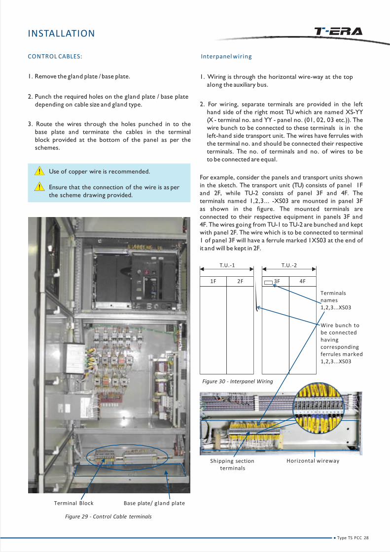
Terminal Block Base plate/ gland plate
Figure 29 - Control Cable terminals
INSTALLATION
CONTROL CABLES:
1. Remove the gland plate / base plate.
2. Punch the required holes on the gland plate / base plate
depending on cable size and gland type.
3. Route the wires through the holes punched in to the
base plate and terminate the cables in the terminal
block provided at the bottom of the panel as per the
schemes.
Use of copper wire is recommended.
Ensure that the connection of the wire is as per
the scheme drawing provided.
Interpanel wiring
1. Wiring is through the horizontal wire-way at the top
along the auxiliary bus.
2. For wiring, separate terminals are provided in the left
hand side of the right most TU which are named XS-YY
(X - terminal no. and YY - panel no. (01, 02, 03 etc.)). The
wire bunch to be connected to these terminals is in the
left-hand side transport unit. The wires have ferrules with
the terminal no. and should be connected their respective
terminals. The no. of terminals and no. of wires to be
to be connected are equal.
For example, consider the panels and transport units shown
in the sketch. The transport unit (TU) consists of panel 1F
and 2F, while TU-2 consists of panel 3F and 4F. The
terminals named 1,2,3... -XS03 are mounted in panel 3F
as shown in the figure. The mounted terminals are
connected to their respective equipment in panels 3F and
4F. The wires going from TU-1 to TU-2 are bunched and kept
with panel 2F. The wire which is to be connected to terminal
1 of panel 3F will have a ferrule marked 1XS03 at the end of
it and will be kept in 2F.
Figure 30 - Interpanel Wiring
T.U.-1 T.U.-2
1F 2F 3F
Terminals names 1,2,3...XS03
Wire bunch to be connected having corresponding ferrules marked 1,2,3...XS03
4F
Horizontal wirewayShipping section terminals
Type TS PCC 28
INSTALLATION
Figure 32 - ACB lifting truck
ACB
• Unpack the ACB properly to avoid damaging it using
crowbar Figure 32.
• Open the ACB compartment door using the camlock
key provided.
• Rack out the cradle using the racking handle.
• If cradle movement is not smooth, apply contact grease.
Also check for the free movement of safety shutters.
• Put the ACB on the cradle with the help of ACB lifting
truck Figure 33.
Note that ACB lifting truck will be supplied only if asked bythe customers.
In case if you dont have ACB lifting truck please contact thesales team for ordering the same or email [email protected]
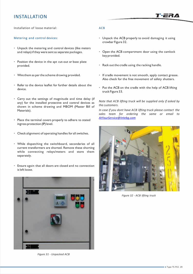
Installation of loose material:
Metering and control devices:
• Unpack the metering and control devices (like meters
and relays) if they were sent as separate packages.
• Position the device in the apt cut-out or base plate
provided.
• Wirethem as per the scheme drawing provided.
• Refer to the device leaflet for further details about the
device.
• Carry out the settings of magnitude and time delay (if
any) for the installed protective and control devices as
shown in scheme drawing and MBOM (Master Bill of
Materials).
• Place the terminal covers properly to adhere to stated
ingress protection (IP) level.
• Check alignment of operating handles for all switches.
• While dispatching the switchboard, secondaries of all
current transformers are shorted. Remove these shorting
while connecting relays/meters and store them
separately.
• Ensure again that all doors are closed and no connection
is left loose.
Figure 31 - Unpacked ACB
Type TS PCC 29

INSTALLATION
Loading in panel:
1. Pull-out the Cradle Rails & ensure that position indication
shows ‘DISCONNECTED’
2. Load the ACB using crane. Even bottom trolley can be
used.
Improper loading of ACB may lead to personal
injury and damage to product.
4. Gently push the ACB to DISCONNECTED position and
close the Panel door.
If equipped with Rating Error Preventor, Cradle will not
accept ACB of different rating.
5. Keeping the OFF button pressed, open the Racking
Shutter. In case panel door is open, also gently defeat
Racking Interlock.
3. Ensure that ACB rests correctly in 2 slots on either side
of cradle rail.6. Rack-in the ACB to Service position. Two almost
-simultaneous ‘Click’ sounds confirm ‘CONNECTED’
position.
Excessive forceful racking-in beyond Connected
position lead to product damage.
Type TS PCC 30

INSTALLATION
Figure 33 - Installation of Control Transformer
Control Transformers
1. Unpack the Control Transformer.
2. Open the compartment door in which the Control
Transformer is to be installed.
3. Bolt the Control Transformer to the base plate.
4. Terminate the primary and secondary wires of the
transformer on the respective terminals.
5. The primary wire has a ferrule with capital letters while
that of the secondary is with unicase Figure 32.
6. Check the connections and tighten the bolt.
Type TS PCC 31

INSTALLATION
INSTALLING AN EXTENSION PANEL
Tojoin an extension panel to existing TS,
1. Remove the end cover of existing TS at the joining end 3. Necessary busbars / fishplates are supplied with the
Figure 35. extension panel.
2. Follow instructions listed in ‘Connection of TUs’ under 4.Place the end cover on the newly added panel.
Installation on page no. 19.
Ensure that both power and control circuits are switched off before taking the end cover off the TU.
Type TS PCC 32
End Cover
Figure 34 - Extension of Panel

Type TS PCC 33

SITE TESTING
Type TS PCC 34

SITE TESTING
TESTING YOUR SWITCHBOARD
1. Keep all power circuit switches ON.
2. Isolate all parallel paths.
3. Ensure all power circuits are connected.
4. Measure all insulation resistance (IR) values between
phases with respect to earth, phases with respect to
neutral and between phase and earth with respect to
neutral with a 500 V megger and compare with the table
below.
In case megger trips while testing, go on isolating one
panel fromthe switchboard till the fault isfound.
B)Dielectric Strength Testat 2.5KV for 1 Sec.
Check (phase)
a) R/Y/B/N
b) R/Y/B
c) R/Y
d) R
With respect to
…….E
…….N
…….B
…….Y
5. Carry out HV test at 2 KV for control circuits and at 2.5 KV
for power circuit for one second and limit the voltage to
8 5 % of the preceding value for every consecutive test.
TESTING OF AIR CIRCUIT BREAKER(ACB)
1. Check rating & type of the ACB are as per MBOM
drawing.
2. Check the door interlocks of the ACB. Door should not
open when the ACB is in SERVICE or TEST position. In
these positions, it should be possible to open the door
only with door interlock defeat facility.
3. Carry out electrical function checks on the ACB with
respect to control schematics. (Simulating each logic
condition).
4. Check anti pumping operation of the ACB. (Press the
closePB (Push Button) and keep it pressed, the ACB
closes). Now reset the trip command and then press the
close PB, ACB closes now. Hence the anti pumping
feature of ACB is checked.
5. If the ACB has in-built protection release, it should be
tested with the respective testing kit.
6. Carry out functional tests on the ACB as per control
wiring scheme of the respective feeder.
TESTING POTENTIAL TRANSFORMERS (VoltageTransformer and Control Transformer)
A) Insulation Resistance Test with 500V Megger before andafter H.V.Test (All values in M.ohms).
1. Check nameplates and ensure they are as per drawings.
2. Check PT Secondary is wired correctly with proper gauge
of conductor.
3. Check PT mounting and ensure they are adequately
supported.
4. Check PTcircuit's earth link.
5. Check the polarity of PT. Using a battery operated polarity
tester, check that positive EMF is induced between
terminals S1 and S2 when a positive current pulse is
applied between P1 to P2.
6. Check ratio of all cores. Conduct ratio test by applying
1 phase 240V across the primary. Note voltage at
secondary. Calculate the ratio tabulate and compare the
value with the nameplate values.
7. Measure winding resistance.
8. Check tightness of all connecting terminals.
TESTING OF METERS AND TRANSDUCERS:
1. Inspect all meters and transducers for proper
mounting and for any damage.
2. Testwith calibrated meters.
3. Check CT and VT connections with particular reference
to their polarities for power type meters wherever they
are provided.
R Y B N
E 0.5 0.5 0.5 0.5
N 0.5 0.5 0.5 ~
B 0.5 0.5 ~ ~
Y 0.5 ~ ~ ~
Type TS PCC 35

SITE TESTING
4. Check for the earthing of meters and transducers as
per the drawing.
Type TS PCC 36
TESTING OF RELAYS:
1. Inspect for propermounting and for any breakage.
2. Ensure all gagging of moving parts are removed.
3. Check nameplate details as per specification.
4. Set the relay as per setting sheet, (protection co-
ordination) and check for its operation at set values.
TESTING CURRENT TRANSFORMERS (Cts):
3. Check CT secondary links are properly connected as per
the scheme drawing.
4. Check CT mountings and ensure they are adequately
supported and clamped.
5. Check polarity of CT. Use a battery operated polarity
tester. Depending upon the type of CT apply a positive
pulse at P1 and a negative pulse at P2 (where P1 and
P2 are two ends of the coil). Connect a null
deflection galvanometer and observe the direction. It
should be towards the right hand side.
6. Measure winding resistance of CT secondary using a
multi meter in ohmmeter mode in case of protective CT
core to ensure that the CTsecondary is not open.
7. Check tightness of all bolts, clamps connecting terminals.
8. Check for earthing connections of CTis as per drawing.
1. Check nameplates and ensure CTs they are as per
drawings and specifications.
2. Check wether the CT secondary is wired correctly with
propergauge of conductor.

CHECK POTENTIAL PROBLEMS
Verification of vendor documents Incomplete documentation
Verification of General Arrangement &
Mechanical check
Cleaning
Wobbling of doors
Misalignment of pillars
Alignment of handle
• Appearance (Visual)
• Dimension
• Verticality & Waviness
Powder Coating:
• Surface Finish Glossy or Matt
• Paint Shade
• Dry Film Thickness
Orange peel effect, Bubbles, Dent Marks, Pinholes
Paint shade difference, low gloss
DFT low /high
Busbar Arrangement Busbar coupling not ok
Fishplate & harwdware missing
Busbar& Power Joints Tightness Loose joints, No red marking, Wrong H / Wsize
Pull test for crimping and termination and
visual inspection of wiring
Loose crimping
Wrong lug used
Loose termination
Poor wire bunching & dressing
Clearance Low clearance
Partition Provision (Form of Separation) Shroud not provided at Live terminal, Cover / Barrier missing
Degree of Protection (IP) Pinholes at door corners, control plate gasket not proper,
extra holes on pillars / end cover / doors
CT Polarity Wrong CT wiring, mixing of protection & metering CT wires,
neutral CT connection wrong
Current Injection (Primary / Secondary) Wrong wiring of trip circuit / protection circuit, wrong termination
at relays
Insulation Resistance (Megger) Low IR value
Dielectric Test (High Voltage) for Power &
Control Circuit
Presence of foreign material in Busbar zone, insulation puncture
Type TS PCC 37
SITE TESTING

PRE-ENERGISING
CHECKS
Type TS PCC 38

PRE-ENERGISING CHECKS:
Ensure the following checks are carried out before energizing:
Sr.No. Check Point OK
1 Overall Appearance & surface finish
2 Verticality of Panels
3 Room ventilation
4 Fire Extinguisher
5 Rubber mats of grade 1100 V
6 Loose supplied item fitted
7 Verification of BOM as per GA drawing
8 T ightness of busbar Joints
9 Wiring check as per scheme drawings
10 Phase sequence / Polarity check
11 CT & PT ratio check (on Sampling)
12 Insulation Resistance
13 High Voltage Test (Power Circuit)
14 High Voltage Test (Control Circuit)
15 All doors closed
Type TS PCC 39

COMMISSIONING
OFF ON
Type TS PCC 40
COMMISSIONING
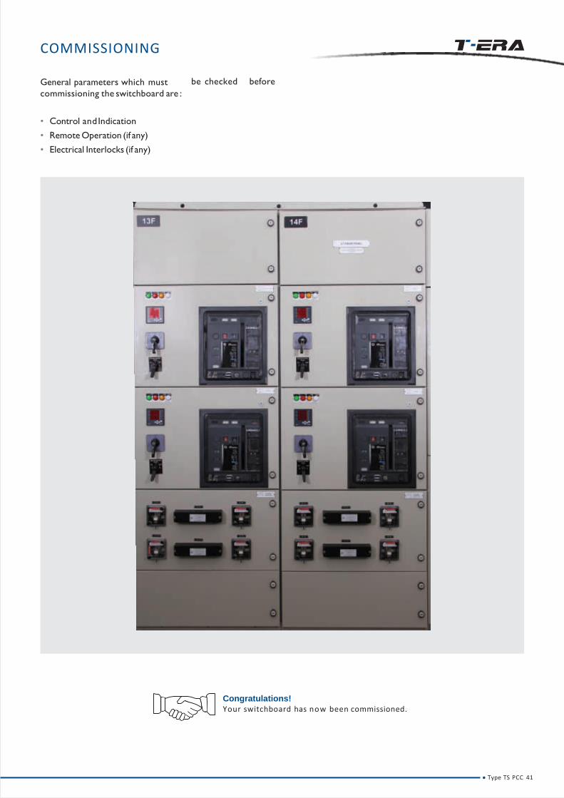
be checked beforeGeneral parameters which must
commissioning the switchboard are :
• Control andIndication
• Remote Operation (if any)
• Electrical Interlocks (if any)
Congratulations!
Your switchboard has now been commissioned.
Type TS PCC 41

OPERATION
Type TS PCC 42

OPERATION
3. Pull the ACB out using pull-out handles.
ACB Interlocks:
• ON-OFF Button padlocking:
To prevent unauthorized access, ON / OFF buttons can be
padlocked orsealed, together or individually.
• Sealing the Release cover:
Protection setting for Release can be secured using a
standard lead seal.
• Safetyshutter padlocking:
Users can padlock top or bottom part of the Safety shutter
to secure access to Line and/or load side.
Padlocking both buttons
Seal ing Either/Both buttons
Lock ing any one button
Racking-out
1. For D/O ACB remove the Transportation Cushion (2
Nos.) & it’s instruction label, before doing racking
operation of the ACB.
2. Keeping OFF button pressed, open the Racking Shutter.
In case ACB is out of the panel or the panel door is
open, gently press Racking Interlock to defeat it. Rack-
out the ACB to Disconnected position.
Note: Once racking shutter is opened, the ACB can
not be closed, even by an electrical closing command.
Note: After removing the racking handle, the racking
shutter automatically recloses only in distinct
‘Connected’ / ‘Test’ and ‘Disconnected’ positions. Hence,
ACB cannot be closed in any Intermediate positions to
ensureUser safety.
Excessive, forceful Racking-out beyond Disconnected
position may lead to Product damage.
Remove Transportation Cushion
Remove Caution Flap
Take out the handle
Type TS PCC 43
Inse
rtth
era
ckin
gh
and
le&
ro
tate
anti
-clo
ckw
ise
OPERATION
Racking Interlock defeat:
Tools required: None
Racking interlock prevents opening of racking shutter and
thus, racking in / out of the ACB when panel door is open.
If it is necessary to rack-out the ACB with panel door open,
racking interlock can be defeated. For opening racking
shutter with panel door open, gently push the racking
interlock lever in addition to keeping 'OFF' button pressed.
It is recommended to carry-out racking operation only
with panel door closed.
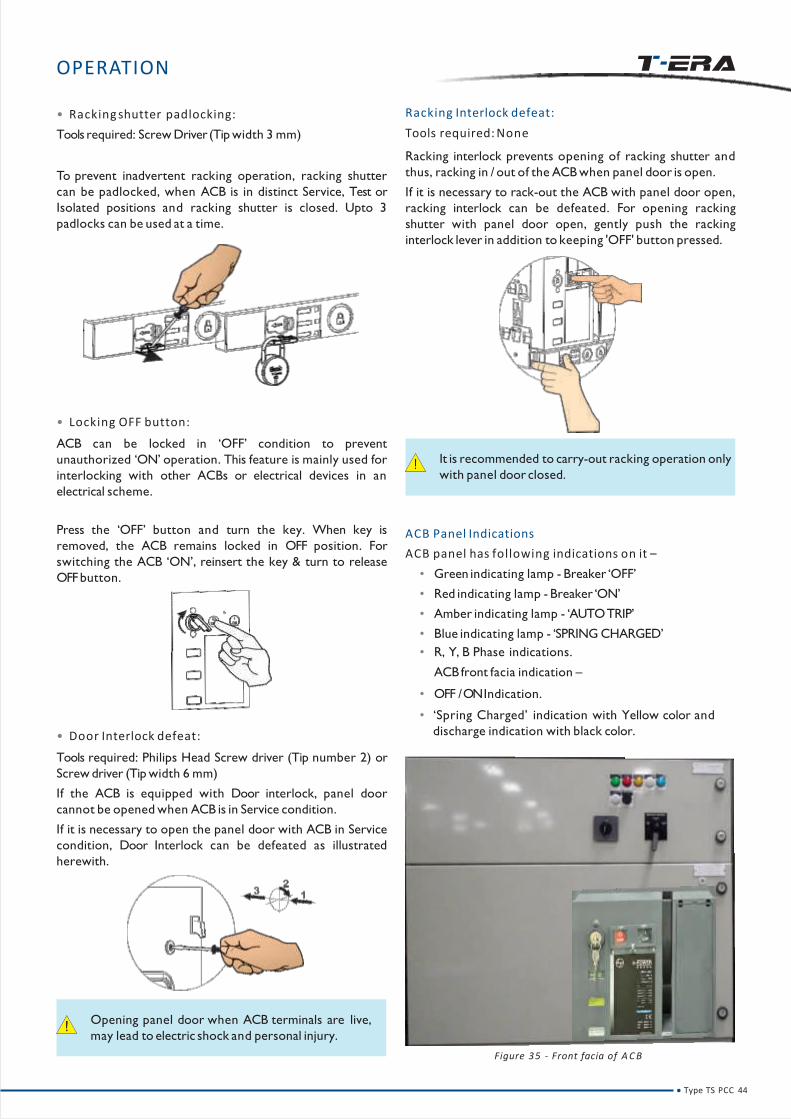
ACB Panel Indications
ACB panel has following indications on it –
• Green indicating lamp - Breaker ‘OFF’
• Red indicating lamp - Breaker ‘ON’
• Amber indicating lamp - ‘AUTOTRIP’
• Blue indicating lamp - ‘SPRING CHARGED’
• R, Y, B Phase indications.
ACB front facia indication –
• OFF /ON Indication.
• ‘Spring Charged’ indication with Yellow color and
discharge indication with black color.
• Racking shutter padlocking:
Tools required: Screw Driver (Tip width 3 mm)
To prevent inadvertent racking operation, racking shutter
can be padlocked, when ACB is in distinct Service, Test or
Isolated positions and racking shutter is closed. Upto 3
padlocks can be used at a time.
• Locking OFF button:
ACB can be locked in ‘OFF’ condition to prevent
unauthorized ‘ON’ operation. This feature is mainly used for
interlocking with other ACBs or electrical devices in an
electrical scheme.
Press the ‘OFF’ button and turn the key. When key is
removed, the ACB remains locked in OFF position. For
switching the ACB ‘ON’, reinsert the key & turn to release
OFFbutton.
• Door Interlock defeat:
Tools required: Philips Head Screw driver (Tip number 2) or
Screw driver (Tip width 6 mm)
If the ACB is equipped with Door interlock, panel door
cannot be opened when ACB is in Service condition.
If it is necessary to open the panel door with ACB in Service
condition, Door Interlock can be defeated as illustrated
herewith.
Opening panel door when ACB terminals are live,
may lead to electric shock and personal injury.
Figure 35 - Front facia of A C B
Type TS PCC 44

Type TS PCC 45

MAINTENANCE
Type TS PCC 46
MAINTENANCE
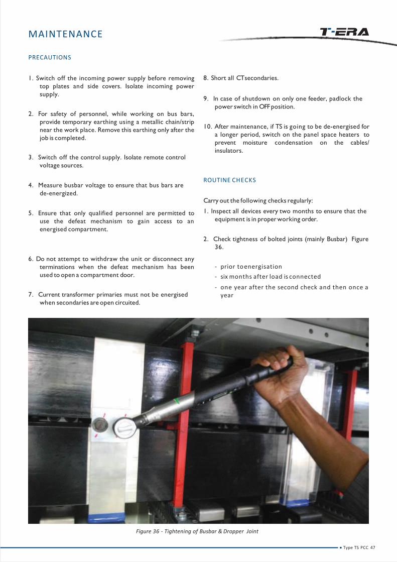
Figure 36 - Tightening of Busbar & Dropper Joint
PRECAUTIONS
1. Switch off the incoming power supply before removing
top plates and side covers. Isolate incoming power
supply.
2. For safety of personnel, while working on bus bars,
provide temporary earthing using a metallic chain/strip
near the work place. Remove this earthing only after the
job is completed.
3. Switch off the control supply. Isolate remote control
voltage sources.
4. Measure busbar voltage to ensure that bus bars are
de-energized.
5. Ensure that only qualified personnel are permitted to
use the defeat mechanism to gain access to an
energised compartment.
6. Do not attempt to withdraw the unit or disconnect any
terminations when the defeat mechanism has been
used to open a compartment door.
7. Current transformer primaries must not be energised
when secondaries are open circuited.
8. Short all CTsecondaries.
9. In case of shutdown on only one feeder, padlock the
power switch in OFFposition.
10. After maintenance, if TS is going to be de-energised for
a longer period, switch on the panel space heaters to
prevent moisture condensation on the cables/
insulators.
ROUTINE CHECKS
Carry out the following checks regularly:
1. Inspect all devices every two months to ensure that the
equipment is in properworking order.
2. Check tightness of bolted joints (mainly Busbar) Figure
36.
- prior toenergisation
- six months after load is connected
- one year after the second check and then once a year
Type TS PCC 47

MAINTENANCE
3. Inspect all wiring for wear and cuts every two months.
4. Clean and lubricate the stab-in contacts once a year
with HPMPL (EXXON)grease.
5. Remove burnt out fuses if any.
6. Check terminal block contacts for loose connections.
7. Examine indicating lamps and replace if required.
8. Ensure all safety interlocks are functional and in proper
working order every two months.
9. Look for indications of overheating, sparking or
insulation breakdown on the busbars.
10. Inspect all auxiliary and control circuits every two
months for desired functioning.
11. Grease racking screw and telescopic rails at least once a
year. Use grease 'HP-LETHON-2' or 'SYNTHOLUBE-20 of
HJ Leach & Co.
12. Ensure that the earth wires are connected to the main
earth bar (except electronic device earthing).
13. Ensure no tools or loose materials are left inside the TS
as these can cause faults.
14. Keep the switchboard free of dust. Use a vacuum
cleaner to remove the dust.
Do not operate equipment whose arc chutes are removed.
Overheating at terminals and joints can result in serious accidents including flashovers. Regulartemperature checks at termination using an 'Infrared Temperature scanner' will help to detect anyoverheating for timely preventive action.
If ACB is not being racked-out in a year, it is recommended to carry-out racking operation of the ACB as apart of routine maintenance.
ACB Maintenance:
Type TS PCC 48
Nature of
MaintenanceSchedule/Frequency Actions
Routine
Quarterly Temperature check at termination
Yearly
Open & Re-close the ACB
Rack-out & Rack-in the ACB
Inspect Arc Chutes for erosion
Inspect Contacts for erosion
1 Year or 500 operations (whichever
is earlier)Greasing of Operating Mechanism
Specific
When any Electrical accessory
needs replacementReplace the specific accessory
When ACB clears a major fault
Inspect Arc Chutes for erosion & replace,
if required
Inspect contacts for erosion & replace
Main Contacts, if required
In case of an abnormal external
event, such as flashover in panel
Inspect Jaw Contacts & replace, if required
Inspect Cradle Terminals and replace, if
required
On completion of Electrical life Replace all Arc Chutes
Replace all Main Contacts
MAINTENANCE
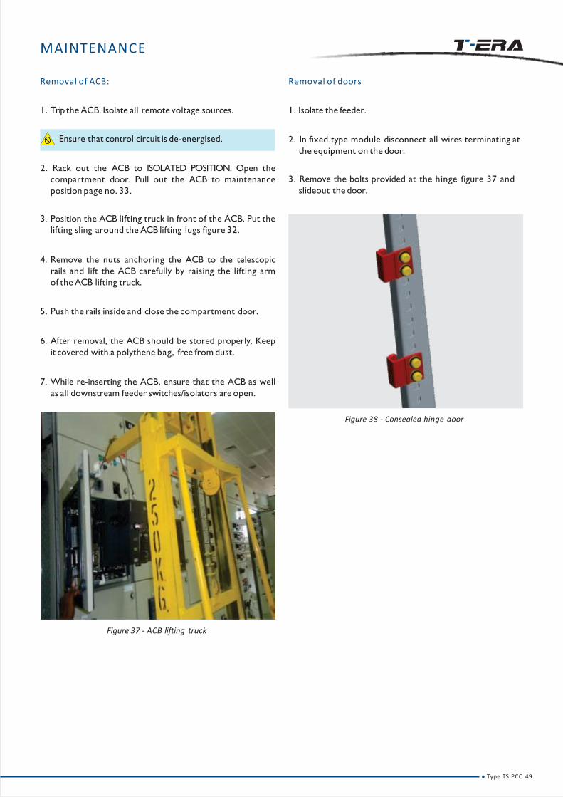
Figure 37 - ACB lifting truck
Figure 38 - Consealed hinge door
Removal of ACB:
1. Trip the ACB. Isolate all remote voltage sources.
Ensure that control circuit is de-energised.
2. Rack out the ACB to ISOLATED POSITION. Open the
compartment door. Pull out the ACB to maintenance
position page no. 33.
3. Position the ACB lifting truck in front of the ACB. Put the
lifting sling around the ACB lifting lugs figure 32.
4. Remove the nuts anchoring the ACB to the telescopic
rails and lift the ACB carefully by raising the lifting arm
of the ACB lifting truck.
5. Push the rails inside and close the compartment door.
6. After removal, the ACB should be stored properly. Keep
it covered with a polythene bag, free from dust.
7. While re-inserting the ACB, ensure that the ACB as well
as all downstream feeder switches/isolators are open.
Removal of doors
Type TS PCC 49
1. Isolate the feeder.
2. In fixed type module disconnect all wires terminating at
the equipment on the door.
3. Remove the bolts provided at the hinge figure 37 and
slideout the door.

TROUBLE
SHOOTING
Type TS PCC 50

TROUBLE SHOOTING
• Switch on control MCB / control fuse, ensure interlocks
are active and turn on the feeder.
• If control MCB / control fuse trips verify the field
terminations on the SIC.
• If the control MCB has not tripped but the breaker still
fails to operate, then check the helth of the control circuit
using a line tester.
• If the problem persists, check for component failure.
• After trouble-shooting ensure that the ACB is racked in to
serviceposition.
If the problem persist,contact your nearestsalesoffice
oremail your query to [email protected]
On a live switchboard :
• Identify fault location using indicating lamps or
monitoring system.
• Reset the relay orMCB after the fault has been cleared.
• Check if breaker has been properly racked in to service
position.
• Check if respective MCBs are in ‘ON’ position.
• Check for availability of supply at the control MCB
connected to the auxiliary bus.
• If control fuse is used, check the health of the fuse.
Replace if necessary.
• Check the termination at shipping section terminals.
(These are terminals for terminating wires running
between panels)
• Check whether terminations from field connections are :
1. Correctly terminated
2. Tight
• Rack out the ACB to test position.
Periodical tightening of terminations as prescribed
in commissioning manual of the ACB should be
followed.
Type TS PCC 51
TROUBLE SHOOTING
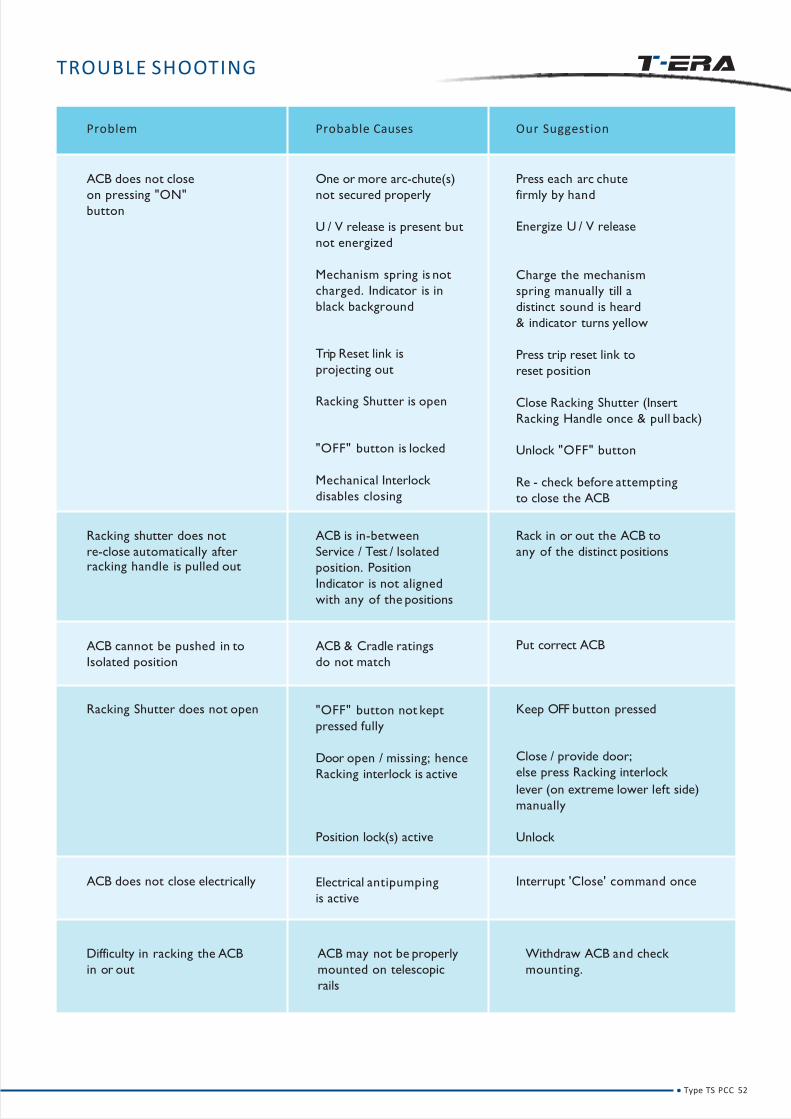
Problem Probable Causes Our Suggestion
ACB does not close
on pressing "ON"
button
One or more arc-chute(s)
not secured properly
U / V release is present but
not energized
Mechanism spring is not
charged. Indicator is in
black background
Trip Reset link is
projecting out
Racking Shutter is open
"OFF" button is locked
Mechanical Interlock
disables closing
Press each arc chute
firmly by hand
Energize U / V release
Charge the mechanism
spring manually till a
distinct sound is heard
& indicator turns yellow
Press trip reset link to
reset position
Close Racking Shutter (Insert
Racking Handle once & pull back)
Unlock "OFF" button
Re - check before attempting
to close the ACB
Racking shutter does not
re-close automatically afterracking handle is pulled out
ACB is in-between
Service / Test / lsolated
position. Position
Indicator is not aligned
with any of the positions
Rack in or out the ACB to
any of the distinct positions
ACB cannot be pushed in to
Isolated position
ACB & Cradle ratings
do not match
Put correct ACB
Racking Shutter does not open "OFF" button not kept
pressed fully
Door open / missing; hence
Racking interlock is active
Position lock(s) active
Keep OFF button pressed
Close / provide door;
else press Racking interlock
lever (on extreme lower left side)
manually
Unlock
ACB does not close electrically Electrical antipumping
is active
Interrupt 'Close' command once
Difficulty in racking the ACB
in or out
ACB may not be properly
mounted on telescopic
rails
Withdraw ACB and check
mounting.
Type TS PCC 52
RECOMMENDATIONS
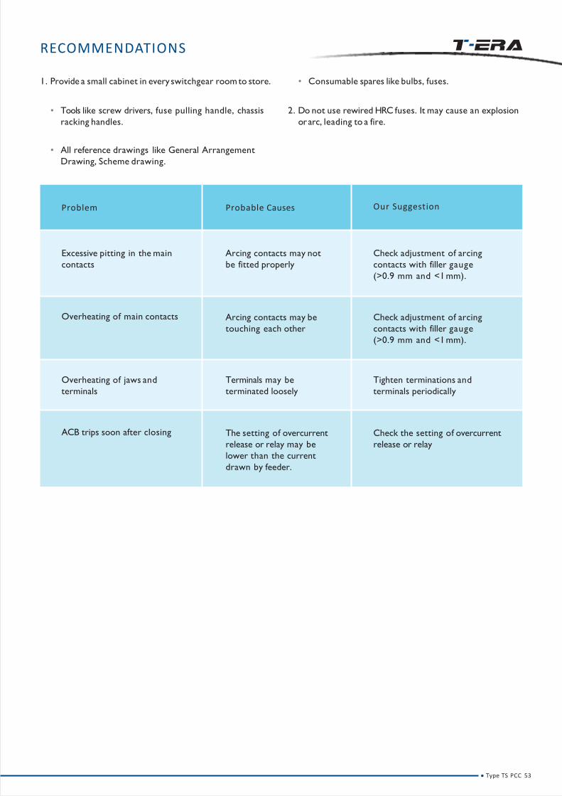
Problem Probable Causes Our Suggestion
Excessive pitting in the main
contacts
Arcing contacts may not
be fitted properly
Check adjustment of arcing
contacts with filler gauge
(>0.9 mm and <1mm).
Overheating of main contacts Arcing contacts may be
touching each other
Check adjustment of arcing
contacts with filler gauge
(>0.9 mm and <1mm).
Overheating of jaws and
terminals
Terminals may be
terminated loosely
Tighten terminations and
terminals periodically
ACB trips soon after closing The setting of overcurrent
release or relay may be
lower than the current
drawn by feeder.
Check the setting of overcurrent
release or relay
Type TS PCC 53
1. Provide a small cabinet in every switchgear room to store.
• Tools like screw drivers, fuse pulling handle, chassis
racking handles.
• All reference drawings like General Arrangement
Drawing, Scheme drawing.
• Consumable spares like bulbs, fuses.
2. Do not use rewired HRC fuses. It may cause an explosion
orarc, leading to a fire.

LIST OF FIGURES
Figure 1 - PCC panel 03
Figure 2 - Door Openview 03
Figure 3 - Double Deck arrangement of busbars 10
Figure 4 - Busbar Support 10
Figure 5 - Four linkssupport 10
Figure 6 - Two links support 10
Figure 7 - Auxbus Chamber 11
Figure 8 - Packing caseDetails 13
Figure 9 - Positioning of TUon truck 13
Figure 10 - Lifting angles 14
Figure 11 - Chain marks on packed TUs 14
Figure 12 - Typical arrangements 21
Figure 13 - Tools 22
Figure 14 - Panel Mounting on ISMC Base Channel / Base Frame 22
Figure 15 - Integral Base Frame 23
Figure 16 - ISMC BaseFrame 23
Figure 17 - Topplate 24
Figure 18 - Busbar joining 24
Figure 19 - Tightning of Busbar joints 24
Figure 20 - Auxbus joining 25
Figure 21 - PCC - PCC Earthbar Coupling 25
Figure 22 - PCC - MCC Earthbar Coupling 25
Figure 23 - Topplate 26
Figure 24 - Power Cable terminals 26
Figure 25 - Power cable terminals 26
Figure 26 - Power cable terminals bottom cable entry 26
Figure 27 - Top Busduct termination 27
Figure 28 - Bottom Busduct termination 27
Figure 29 - Control Cable terminals 28
Figure 30 - Interpanel Wiring 28
Figure 31 - Unpacked ACB 29
Figure 32 - ACB lifting truck 29
Figure 33 - Installation of Control Transformer 31
Figure 34 - Extension of Panel 32
Figure 35 - Front facia of ACB 44
Figure 36 - Tightening of Busbar & Dropper Joint 47
Figure 37 - ACB lifting truck 49
Figure 38 - Consealed hingedoor 49
Type TS PCC 54
LIST OF TABLES
Table1
Table2
Table3
- Technical Data 04
- Size of bolt Torquein m.kg 11
- Size of bolt Torque 24

NOTE
Type TS PCC 55

NOTE
Type TS PCC 56

NOTE
Type TS PCC 57

EM
I24
08
15
S
PT TAMCO INDONESIA (A LARSEN & TOUBRO Group Company)
F-36 , Jalan Jababeka Raya Jababeka Industrial Estate , Cikarang Utara Bekasi , 17530 , West Java , IndonesiaT +62 21 8935070 F +62 21 8935071
Email: [email protected] Website: www.LNTEBG.com© Electrical Systems & Equipment
Registered Office:L&T House, N. M. Marg Ballard EstateMumbai - 400 001, INDIA
Air Circuit Breaker Maintenance:
• Thorough cleaning of the ACB and its cradle
• Mechanical checks such as arcing contact gap, tightness
check, greasing all moving parts
Annual Maintenance Contracts (AMC):
• Electrical substation Maintenance (periodic maintenance
of entire low voltage range of switchgear)
Switchboard Maintenance:
• Erection, Testing and Commissioning
• Commissioning assistance
• Totalvisual check
• Checks- Closing coil, trip coil and auxiliary contacts etc
• Vacuum cleaning
• Tightness check for busbar joints and droppers
• Greasing of all moving parts
• IR(Insulation resistance) and high voltage test• Switchboard maintenance (periodic maintenance of Low
voltage switchboard)• Maintenance workshop
• Retrofitting of the necessary products
Services we offer:

MCC (TX)


Thank you for choosing L&T as your supplier of Low Voltage
Switchgear and giving us the opportunity to serve you.
Please read this manual carefully for proper installation,
safe, easy and efficient operation.
Only authorized and qualified personnel should be allowed
to work on the switchgear. An authorized and qualified
operator is a person having detailed information about
installation and commissioning of switchgear or specially
trained for the maintenance of the switchgear and fully
aware of the hazards caused by unsafe operation. An
operator should also have basic knowledge of First Aid.
The information herein is general for all specifications, part
of which may not be applicable for specific applications or
variants. Refer the following 'as built' documents for any
particular installation:
• Reference list of drawings (RLD)
• Single line drawings
• General Arrangement (GA)drawings
• Master bill of materials (MBOM)
• Scheme drawings
In case of any conflict between this manual and drawings
available with you, the drawings shall take precedence.
For additional information or clarification please send
your queries to [email protected] for quick
resolution.
All our switchgear undergo rigorous testing and qualitychecks at our factory. However, we recommend verificationand testing at site, especially after storage.
Following symbols have been used in this manual to indicate varying levels of danger:
Warning-Highly dangerous- can cause death or serious injury
Caution-Dangerous- cancause injuries or damage the switchgear.
Type TX MCC

CONTENTS
1 INTRODUCTION 1
2 CONSTRUCTION 2
• TECHNICAL DATA 5
• PANEL CONFIGURATIONS 8
• BUSBARS AND DROPPERS 10
• AUXILIARY BUSBARS 11
• TX COMPARTMENTS 12
• FEEDER DETAILS 13
• LOCATION OF POWER AND CONTROL CONTACTS IN VARIOUS POSITIONS 15
• Closed door operations 16
3 HANDLING & TRANSPORTATION 18
• RECEIVING 19
• HANDLING 19
4 STORAGE 22
5 GENERAL SAFETY 24
28
6 INSTALLATION 26
• TYPICAL ARRANGEMENTS 27
• TOOLS 28
• SITE PREPARATION
• ERECTION 28
• FLOOR PREPARATION & PANEL MOUNTING 28
• CONNECTION OF TRANSPORTUNITS & BUSBARS 30
• CONNECTION OF EARTHBARS 31
- MCC-MCC 31
- PCC-MCC 31
• POWER CABLE TERMINATION 32
Type TX MCC

CONTENTS
• TERMINATIONS OF POWER CABLES 33
• Interpanel wiring 39
• INSTALLATION OF LOOSE MATERIAL 39
- Metering and control devices 39
- Modules 40
- Control Transformers 40
• INSTALLING AN EXTENSION PANEL 41
7SITE TESTING 43
• TESTING SWITCHBOARDS 44
• TESTING CURRENTTRANSFORMERS 44
• TESTING POTENTIAL TRANSFORMERS 44
• TESTING METERS AND TRANSDUCERS 45
• TESTING RELAYS 45
• TESTING CONTROL CIRCUITS 45
8 PRE-ENERGIZING CHECKS 47
• COMMISSIONING 49
• OPERATION 51
• MAINTENANCE 55
- PRECAUTIONS 56
- ROUTINE CHECKS 56
- REMOVAL OF POWER CONTACTS 57
- REMOVAL OF DOORS 57
9TROUBLE SHOOTING 59
10 RECOMMENDATIONS 61
11 LIST OF FIGURES 62
12 LIST OF TABLES 63
Type TX MCC
Type TX MCC

INTRODUCTION
IMPORTANTNOTE
Only the Specific written Technical Instructions supplied by L&T must be used. Our products must only be commissioned,
operated, serviced, repaired or decommissioned in accounts with Technical Instructions which have been supplied by the
manufacturer. Non Compliance with this instruction may result in serious damage to the product and its associated items, as
well as health hazard ormortal danger.
WARRANTY
Ourproducts are subjected to factory inspection and testing according to the applicable standards and provisions.
The correct function and the service life of the switchgear are influenced greatly by compliance with the installation,
commissioning and operating conditions stipulated in this manual.
Non-compliance with these provisions may compromise warranty claims.
Any local provision which does not contradict the specifications of this document, especially as regards safety for personnel
and buildings, must be complied with.
L&T cannot be held liable for the possible consequences of:
• Non-compliance with the provisions contained in this manual, which refer to international regulations.
• Non-compliance with the instructions of the suppliers of cables and connecting accessories as regards application and
installation.
• Any aggressive climate conditions (humidity, pollution etc.) prevailing in the immediate environment of switchgear not
suitable to this effect ornot protected accordingly.
• This manual does not contain any instructions regarding the mechanical lock-outs to be performed. The work described is
performed on de-energized (on installation) ormechanically locked - out (decommissioned) switchgear.
Type TX MCC 1

CONSTRUCTION
Type TX MCC 2

CONSTRUCTION
Figure 1 - Floor mounted panel
• Motor Control Centre type TXis a free-standing and floor
mounting switchboard available in single front and back
to back versions. Suitable for indoor installation.
• Each vertical panel is divided into distinct zones for
busbars, feeders, power cabling and auxiliary busbars
Figure 2.
• The compartment houses modules for individual feeders
comprising equipment such as fuse switches, MCCB,
contactors, relays, timers and associated auxiliary
equipments.
• For optimum utilization of panel space, modules have
variable width and variable heights which is further
explained on Page No. 9.
• The structural members of the panel are closed profiled
providing higher strength against mechanical forces
generated.
Type TX MCC 3

CONSTRUCTION
Figure 2 - Different Compartments
160mm Quarter Width Module
160mm Half Width Module
320mm Half Width Module
320mm Full Width Module
Fractional width modules
Cam-Lock
Auxiliary busbar zone
Power Cabling Area
Type TX MCC 4

TECHNICAL DATA
L&T´s TX range of Low Voltage Motor Control Centers comply with IEC 61439-Part 1 & 2. It is designed to enhance safety of the users. Its modular construction facilitates logistics, installation, commissioning and maintenance.
Table No. 1
Designation Motor Control Center (MCC) Type TX
Standards and specifications
Power Switchgear and Controlgear (PSC) Assemblies
IEC 61439 - 2, BS EN 61439 - 2
Testing under conditions of arcing due internal faults
to IEC 61641
Insulation characteristics
Clearance > 20 mm
Creepage distances > 20 mm
Overvoltage category II / III / IV
Pollution degree 3
Field condition Inhomogeneous (non-uniform)
Electricalcharacte-ristics
Voltage ratings
Rated operational voltage (Ue) up to 690 V
Rated insulation voltage (Ui) 1000 V
Rated impulse withstand voltage (Uimp) 6 / 8 / 12 kV
Rated frquency (fn) 50 / 60 Hz
Type TX MCC 5

TECHNICAL DATA
Table No. 1
Electricalcharacte-ristics
Main Horizontal busbars:
Rated current (InA) up to 6300 A
Rated peak withstand current (Ipk) up to 220 kA
Rated short-time withstand current (Icw) up to 100 kA, 1s
up to 50 kA, 3s
Current ratings Vertical Distribution busbars for MCC:
Rated current (InA) up to 2000 A
Rated peak withstand current (Ipk) up to 220 kA
Rated short-time withstand current (Icw) up to 100 kA, 1s
up to 50 kA, 3s
Rated conditional short-circuit current (Icc) up to 80 kA
Permissible conditional short-circuit current up to 100 kA
Internal Arc fault conditions
Duration 500 ms
Acceptance Criteria as per IEC 61641 1 to 7
In accrodance with IEC 60529:
Mechanical characte-ristics
Degree of Protection
External IP 30 / IP 40 / IP 42 / IP 54
Internal IP 2X / IP XXB / IP 4X / IP XXD
Mechanical Impact as per IEC 62262 IK 08 / IK 09 / IK 10
Forms of as per IEC 61439 - 2 Form 1 to Form 4
Separationas per BS EN 61439 - 2 upto Form 4, Type 6
Height (mm) 2200, 2400
Dimensions Width (mm) 700, 900, 1000 (MCC)
Depth (mm) 600, 1000, 1100 (MCC)
Surface Treatment
Structure Alu-zinc / powder coated / painted
Internal Components Alu-zinc / powder coated / painted
External Components powder coated / painted
Resitance toDamp heat cycling test IEC 60068-2-30
CorrosionSalt mist test IEC 60068-2-11
Plastic components
Flame retardant, self-extinguishing, Halogen-free
IEC 60695-2-10, IEC 60695-2-11
Type TX MCC 6

TECHNICAL DATA
Table No. 2
Material
Aluminium
Panel
Version
Single Front (Side cable entry)
Single front (Rear cable entry)
Back to back
configuratio
n
Height (mm)
2400
s
Width (mm)
900 / 1000
700
900
Depth
(mm)
600 / 1000
1000
1100
Depth
including
doors (mm)
644 / 1044
1044
1144
Back to back 1000 1000 1044
Copper
Single Front (Side cable entry)
Single front (Rear cable entry)
Back to back
Back to back
2200 / 2400
900 / 1000
700
900
1000
600/ 1000
1000
1100
1000
644
1044
1144
1044
Type TX MCC 7

CONSTRUCTION
PANEL CONFIGURATIONS
*Dimensions do not includedoors
Cabling Area
*F Front Side
*R Rear Side
(All dimensions are in mm)
SINGLE FRONT SINGLE FRONT
900 1000
2200/2
400
*F
A
B C
D E
F
G
*F
A
B C
D E
F
G
SINGLE FRONT
900
*F
A
B C
D E
F
G
2200/2
400
2200/2
400
30
260
540
600
*F
30360
540
30
600
*F
1000
540
*F
260
SINGLE FRONT
10002200/2
400
*F
A
B C
D E
F
G
1000
540
*F
365 30
Type TX MCC 8
CONSTRUCTION
PANEL CONFIGURATIONS
Cabling Area
*F Front Side
*R Rear Side
640
305
30
1000
*F
1000
360
30
314
314
360
*F
*R
265
30
314
314
265
1100
*F
*R
BACK TO BACKSINGLE FRONT
1000700
*F
A
B C
D E
F
G
2200/2
400
*F
A
B
D E
F
G
2200/2
400
B A C K TO B A C K
900
*F
A
B C
D E
F
G
2200/2
400
(All dimensions are in mm)
*Dimensions do not include doors
Type TX MCC 9

CONSTRUCTION
Figure 5 - Dropper supports
Figure 5.1 - Fully enclosed droppers Figure 5.2 - Fully enclosed droppers (top view)
Figure 4 - Busbar Supports
BUSBARS AND DROPPERS
1. Bus-bars are arranged in a Double deck configuration
Figure 3. They are available in two different arrangements
depending on the rating / busbar material (Aluminum
or Copper), - Double deck non-interleaved (DDNIL)
arrangement – with phase sequence of B-Y-R-N-Double
deck interleaved (DDIL) arrangement with phase
sequence of B-Y-R-B-Y-R-N with 5 0 % neutral ( B-Y-R-B-Y-
R-N-Nin 100% neutral) Figure3.
2. Aluminum and Copper droppers are fixed by supports
and covered to form a fault free zone Figure 5, 5.1 & 5.2.
Figure 3 - Double Deck Arrangement of busbars
Type TX MCC10

Horizontal wireway
CONSTRUCTION
Shipping section terminals
Figure 6 - Aux bus chamber
Up to 12 Auxiliary busbars of 63 A rating can be provided. The Auxiliary busbars are mounted in Nylon Housing to provide
segregation and prevent accidental contact.
Table No. 3
* The above table is indicative and can be configured based on actual requirements.
Wire Way
Block Sr. No. Description
1 Space Heater - Ph
2 Space Heater - N
1 st 3 240 / 110 AC V Aux supply - Ph / Clean Earth Bus
block 4 240 / 110 AC V Aux supply - N
5 110 V DC Aux Bus supply - +ve
6 110 V DC Aux Bus supply - -ve
7 Annunciation Test Bus
8 Annunciation Accept Bus
2 nd 9 Annunciation Reset Bus
block 10 Annunciation Alarm Bus
11 Clean Earth Bus
12 Configurable
AUXILIARY BUSBARS
Type TX MCC11
Auxiliary busbars are located in the top front chamber of the
panel and segregated from main busbars by a metallic
partition.
In back-to-back TX’s, auxiliary busbars are placed in one of
the fronts and tap-offs are taken for the units in both the
fronts.
A horizontal wireway is provided immediately below the
auxiliary busbar for interpanel wiring. Shipping section
terminals are mounted in the horizontal wireway if required.
Figure 6.

TX COMPARTMENTS
The modules are fully interchangeable with optional rating
error preventers. Modules can be replaced quickly, reducing
maintenance downtime.
The modules in TXcome in two broad categories.
a. Fractional Width
b. Full width
Q Q Q Q
H H
F
2Q 2 Q 2Q 2Q
2H 2H
2F
Flexibility of MCC Modules
CONSTRUCTION
1H
Figure 9 - 1 Half(160 mm height)
2H
Figure 10 - 2 Half320 mm height)
2F
Figure 12 - 2 Full (320 mm height)
3F
Figure 13 - 3 Full (480 mm height)
1Q
Figure 7 - 1 Quater(160 mm height)
2Q
Figure 8 - 2 Quater(320 mm height)
1F
Figure 11 - 1 Full (160 mm height)
Type TX MCC12

CONSTRUCTION
Figure 14 - Full width power switch padlocking
Figure 16 - Fractional module padlocking
Figure 15 - Full width module padlocking
FEEDER DETAILS
1. All operations of the Feeder (Module) are possible in
closed door condition. The module can be drawn out
from Service to Isolated position without opening the
compartment door.
2. The feeders are mounted on guiding rails which are
specially designed to provide positive guidance and
smooth movement of the unit.
3. Padlocking facility for power switches is available in
'ON' and 'OFF' positions Figure 14.
4. Module padlocking facility is available in Service, Test and
Isolated position Figure 15 & 16.
Figure 18 - Safety shutter
Figure 17 - Door defeat interlock
Figure 19 - Earthing for full width module
5. Interlocks are provided for safe operation. Module
cannot be racked IN / OUT if the power switch is in ON
condition. Module door cannot be opened in Service
and Test position. However, interlock defeat facility is
available which should be used judiciously Figure 17.
Type TX MCC13
6. Safety shutters are provided for total separation from
live busbar when Module is not inserted in the panel
Figure 18.
7. The 'make first, break last' type scraping earth system is
provided on all draw out units. For full width module,
scrapping earth contact is provided on left side of the
module. Counter part of the scrapping earth is mounted
on vertical connection of the main earthbar Figure 19.
CONSTRUCTION
Figure 20 - Earthing for fractional module module
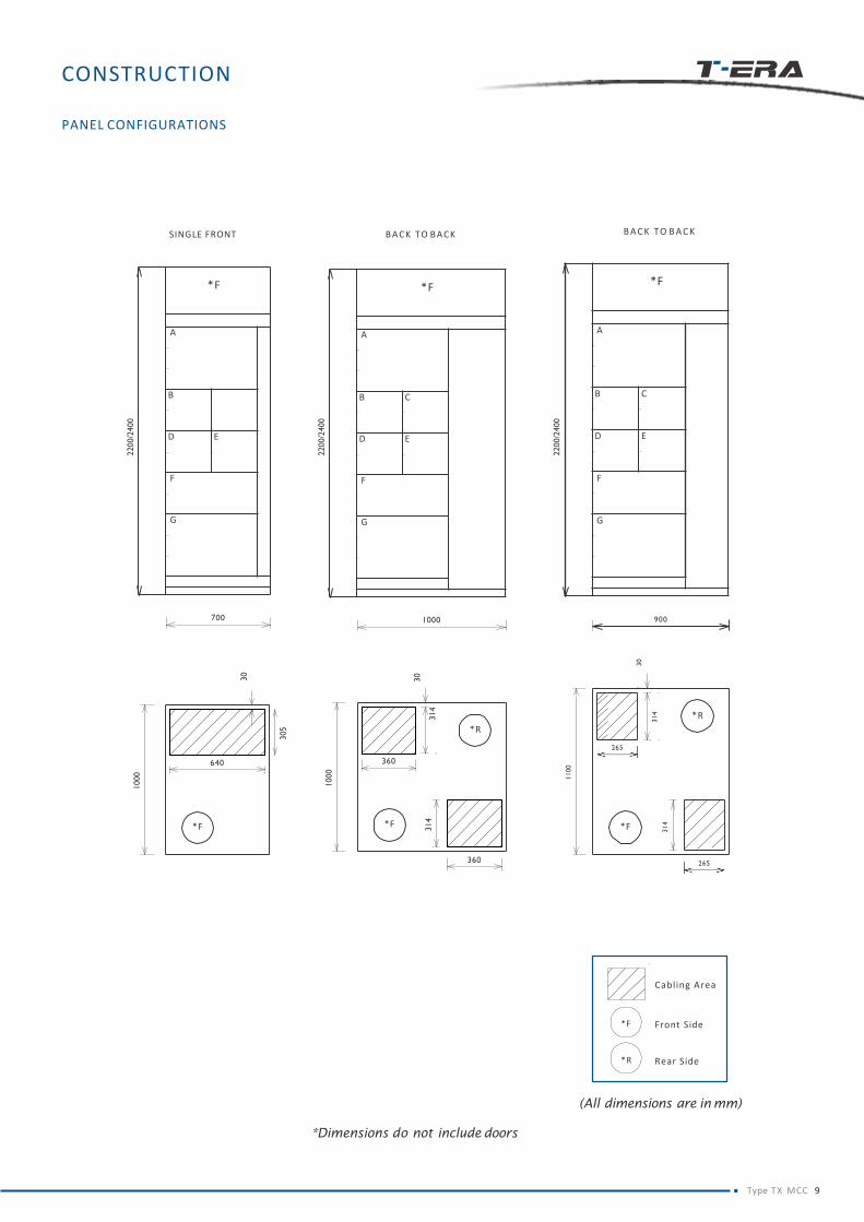
8. For the Fractional Modules, earthing is achieved through
the fixed contact as highlighted in Figure 20 which is
connected to the copper strip running at the bottom of
the tray connecting to vertical earthbar.
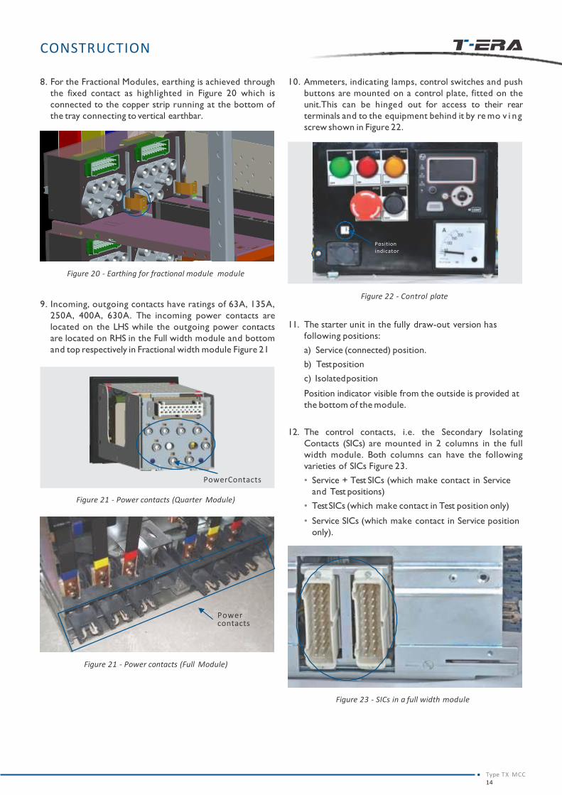
9. Incoming, outgoing contacts have ratings of 63A, 135A,
250A, 400A, 630A. The incoming power contacts are
located on the LHS while the outgoing power contacts
are located on RHS in the Full width module and bottom
and top respectively in Fractional width module Figure 21
Figure 21 - Power contacts (Full Module)
Power contacts
Figure 21 - Power contacts (Quarter Module)
PowerContacts
10. Ammeters, indicating lamps, control switches and push
buttons are mounted on a control plate, fitted on the
unit.This can be hinged out for access to their rear
terminals and to the equipment behind it by re mo v i ng
screw shown in Figure 22.
Figure 22 - Control plate
Position
indicator
11. The starter unit in the fully draw-out version has
following positions:
a) Service (connected) position.
b) Testposition
c) Isolatedposition
Position indicator visible from the outside is provided at
the bottom of the module.
12. The control contacts, i.e. the Secondary Isolating
Contacts (SICs) are mounted in 2 columns in the full
width module. Both columns can have the following
varieties of SICs Figure 23.
• Service + Test SICs (which make contact in Service
and Test positions)
• TestSICs (which make contact in Test position only)
• Service SICs (which make contact in Service position
only).
Figure 23 - SICs in a full width module
Type TX MCC14

POSITION OF THE MODULE
POWER CONTACTS
CONTROL CONTACTS
SERVICE CONNECTED CONNECTED
TEST DISCONNECTED CONNECTED
ISOLATED DISCONNECTED DISCONNECTED
Figure 24 - SICs in a fractional module
State of SICs in various positions:
13. SIC Mounting in Fractional modules Figure 24.
a. Test SICs are not provided in Quarter width modules.
b. All SICs are mounted on the rear Side of the module.
c. Only one SIC block is provided in a quarter width
module and two blocks in a half width module.
SIC's in Fractional Module
CONSTRUCTION
Table No. 4
LOCATION OF POWER AND CONTROL CONTACTS IN VARIOUS POSITIONS
Figure 27 - Isolated position
Figure 26 - Test position
Control contacts
Power contacts
Figure 25 - Service position
Type TX MCC15
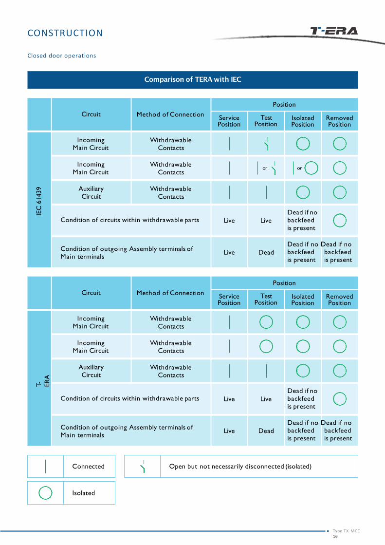
CONSTRUCTION
Comparison of TERA with IEC
Method of ConnectionService Position
Withdrawable Contacts
Closed door operations
Removed Position
Isolated Position
Test Position
Position
Incoming Main Circuit
Circuit
Withdrawable Contacts
Incoming Main Circuit
Withdrawable Contacts
Auxiliary Circuit
Condition of circuits within withdrawable parts Live Live
Dead if no backfeed is present
Condition of outgoing Assembly terminals of Main terminals
Live Dead
Dead if no Dead if no backfeed backfeed is present is present
IEC
61439
oror
Method of ConnectionService Position
Withdrawable Contacts
Removed Position
Isolated Position
Test Position
Position
Incoming Main Circuit
Circuit
Withdrawable Contacts
Incoming Main Circuit
Withdrawable Contacts
Auxiliary Circuit
Condition of circuits within withdrawable parts Live Live
Dead if no backfeed is present
Condition of outgoing Assembly terminals of Main terminals
Live Dead
Dead if no Dead if no backfeed backfeed is present is present
T-
ER
A
Connected Open but not necessarily disconnected (isolated)
Isolated
Type TX MCC16

17

HANDLING AND
TRANSPORTATION
Type TX MCC18
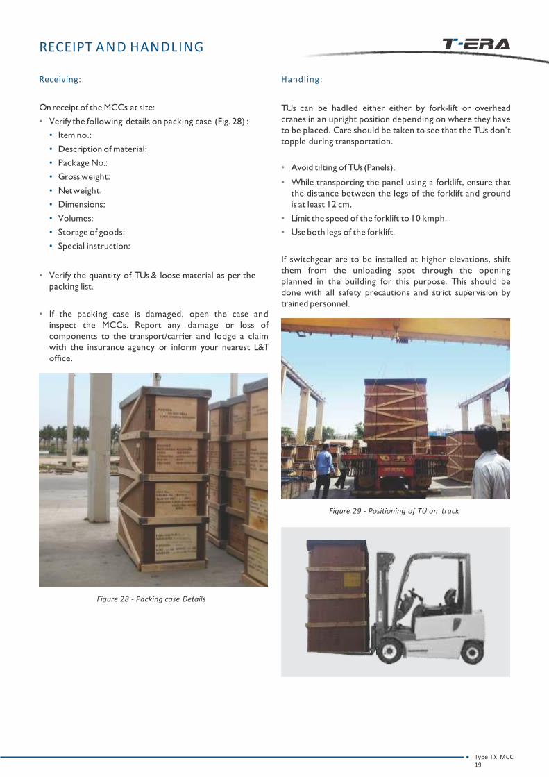
RECEIPT AND HANDLING
Figure 28 - Packing case Details
Receiving:
Onreceipt of the MCCs at site:
• Verify the following details on packing case (Fig. 28) :
• Item no.:
• Description of material:
• Package No.:
• Gross weight:
• Netweight:
• Dimensions:
• Volumes:
• Storage of goods:
• Special instruction:
• Verify the quantity of TUs & loose material as per the
packing list.
• If the packing case is damaged, open the case and
inspect the MCCs. Report any damage or loss of
components to the transport/carrier and lodge a claim
with the insurance agency or inform your nearest L&T
office.
Handling:
TUs can be hadled either either by fork-lift or overhead
cranes in an upright position depending on where they have
to be placed. Care should be taken to see that the TUs don’t
topple during transportation.
• Avoid tilting of TUs(Panels).
• While transporting the panel using a forklift, ensure that
the distance between the legs of the forklift and ground
is at least 12 cm.
• Limit the speed of the forklift to 10 kmph.
• Use both legs of the forklift.
If switchgear are to be installed at higher elevations, shift
them from the unloading spot through the opening
planned in the building for this purpose. This should be
done with all safety precautions and strict supervision by
trained personnel.
Figure 29 - Positioning of TU on truck
Type TX MCC19
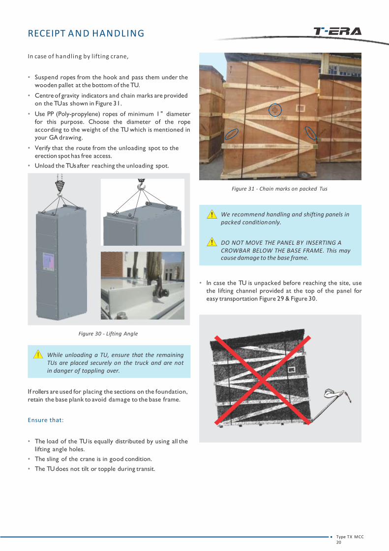
RECEIPT AND HANDLING
o o
oo
o o
oo
In case of handling by lifting crane,
• Suspend ropes from the hook and pass them under the
wooden pallet at the bottom of the TU.
• Centre of gravity indicators and chain marks are provided
on the TUas shown in Figure 31.
• Use PP (Poly-propylene) ropes of minimum 1" diameter
for this purpose. Choose the diameter of the rope
according to the weight of the TU which is mentioned in
your GA drawing.
• Verify that the route from the unloading spot to the
erection spot has free access.
• Unload the TUsafter reaching the unloading spot.
Figure 30 - Lifting Angle
While unloading a TU, ensure that the remainingTUs are placed securely on the truck and are notin danger of toppling over.
If rollers are used for placing the sections on the foundation,
retain the base plank to avoid damage to the base frame.
Ensure that:
• The load of the TU is equally distributed by using all the
lifting angle holes.
• The sling of the crane is in good condition.
• The TU does not tilt or topple during transit.
Figure 31 - Chain marks on packed Tus
We recommend handling and shifting panels in packed conditiononly.
DO NOT MOVE THE PANEL BY INSERTING A CROWBAR BELOW THE BASE FRAME. This maycause damage to the base frame.
• In case the TU is unpacked before reaching the site, use
the lifting channel provided at the top of the panel for
easy transportation Figure 29 & Figure 30.
Type TX MCC20
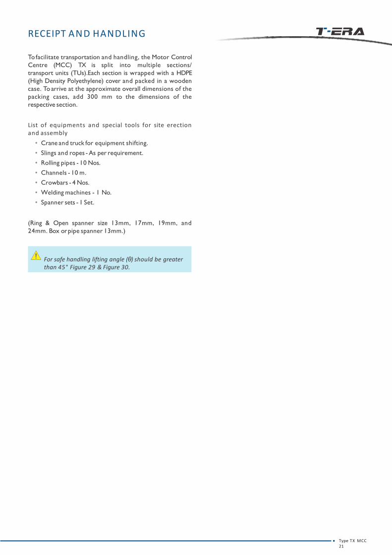
RECEIPT AND HANDLING
Tofacilitate transportation and handling, the Motor Control
Centre (MCC) TX is split into multiple sections/
transport units (TUs).Each section is wrapped with a HDPE
(High Density Polyethylene) cover and packed in a wooden
case. To arrive at the approximate overall dimensions of the
packing cases, add 300 mm to the dimensions of the
respective section.
List of equipments and special tools for site erectionand assembly
• Crane and truck for equipment shifting.
• Slings and ropes - As per requirement.
• Rolling pipes - 10 Nos.
• Channels - 10 m.
• Crowbars - 4 Nos.
• Welding machines - 1 No.
• Spanner sets - 1 Set.
(Ring & Open spanner size 13mm, 17mm, 19mm, and
24mm. Box orpipe spanner 13mm.)
For safe handling lifting angle (θ) should be greater than 45° Figure 29 & Figure 30.
Type TX MCC21

STORAGE
Type TX MCC22
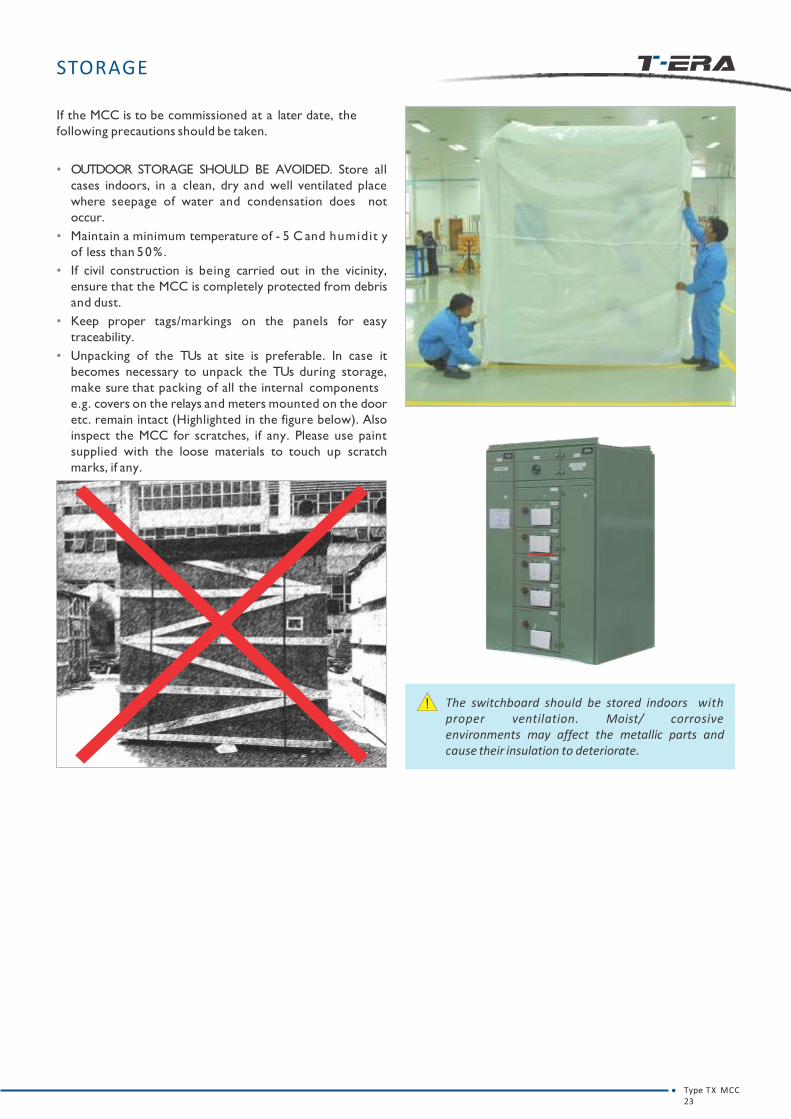
STORAGE
If the MCC is to be commissioned at a later date, the
following precautions should be taken.
• OUTDOOR STORAGE SHOULD BE AVOIDED. Store all
cases indoors, in a clean, dry and well ventilated place
where seepage of water and condensation does not
occur.
• Maintain a minimum temperature of - 5 C and humidit y
of less than 50%.
• If civil construction is being carried out in the vicinity,
ensure that the MCC is completely protected from debris
and dust.
• Keep proper tags/markings on the panels for easy
traceability.
• Unpacking of the TUs at site is preferable. In case it
becomes necessary to unpack the TUs during storage,
make sure that packing of all the internal components
e.g. covers on the relays and meters mounted on the door
etc. remain intact (Highlighted in the figure below). Also
inspect the MCC for scratches, if any. Please use paint
supplied with the loose materials to touch up scratch
marks, if any.
The switchboard should be stored indoors withproper ventilation. Moist/ corrosiveenvironments may affect the metallic parts andcause their insulation to deteriorate.
Type TX MCC23

GENERAL SAFETY
Type TX MCC24

GENERAL SAFETY
While shifting the panel from storage point to erection site:
• Use a lifting crane to load the panel on to the truck.
Ensure that TUs are placed in a vertical position on the
truck.
• Tie the TUsproperly to prevent unwanted movement.
• Refer the previous section for TU handling instructions.
Page No.1.
• Personnel handling the equipment must be skilled and
authorised to handle the intended voltage level.
• All working personnel must be aware of safety
practices.
• Safety shoes should be worn so as to avoid the risk of
any electric shock while at work.
• Gloves and goggles should be used while working in the
proximity of hot and hazardous materials to avoid bodily
injury.
• Appropriate tools and instruments should be used as
stated on page no. 21 for precise workmanship.
• Suitable Caution labels and sign boards should be
erected at the time of installation and testing of boards
as a mark of caution.
Type TX MCC25

INSTALLATION
Type TX MCC26

INSTALLATION
Typical arrangements
644 mm
Type TX MCC27
22
00
mm
Motor Control Centre
Figure 32 - Typical arrangements

INSTALLATION
TOOLS
• Torquewrench
• BushRatchet
• Hydraulic jack
• Rubber mallet
• Clamps
SITE PREPARATION
1. The installation site must be clean and the surface even.
Use shims if the floor is uneven. An uneven foundation
may cause misalignment of sections, bus-bars and
hinged doors of the unit.
2. Walls and ceilings must be plastered with painting
completed.
3. Doorsand windows must be installed.
4. Openings in the floor, wall and ceiling for cables,
conductor pipes, bars and ventilation must be in
accordance with the construction drawings provided.
5. Supporting brackets, beams, enclosures and foundation
frames must be assembled and painted.
6. lf necessary, braces appropriate to the basic
dimensions of the switchgear installation with cross
struts corresponding to the panels must be assembled.
Figure 33 - Tools
Suitable indoor conditions must be maintainedand necessary emergency exits must be providedin the switchgear room.
Excessive temperature fluctuations and highhumidity should be prevented.
Condensation should be prevented.
If the plant´s atmosphere is likely to containexcessive steam or reactive gases comprisingsulphur or chlorine, ensure that the Switchboardis placed in a separate pressurized room.
ERECTION
1. After TUs have reached the installation site, unpack the
TUs and move the packing material to its allocated
area.
2. Check if all components are in place as per your
drawings (MBOM) and the packing list.
3. Vertical sections should be shifted sequentially into the
installation site for ease of installation.
4. The TUs must be carried in an upright position to avoid
the risk of toppling. Refer the section Floor preparation &panel mounting.
5. Place the first TU over the base channel frames erected in
the floor concrete by the civil contractor. Check
correctness of leveling (± 1 mm tolerance per meter is
allowed) and alignment of panels & proceed as per
General Arrangement (GA) Drawings.
6. Maintain clearances as mentioned in GA drawings.
Provide sufficient space on all sides of the panel for
personnel to work conveniently.
FLOOR PREPARATION AND PANEL MOUNTING
Panel can be mounted on the floor either by bolting or tack-
welding with the ISMC Base Channel / Base Frame.
The panel is provided with integral 50 mm base Frame made
of 3mm sheet metal.
Follow the steps listed below to mount the panel.
• Grout / weld the ISMC Base Channel / Base Frame on the
inserts in the floor. Make sure that it is perfectly leveled.
• Place the panel on to the ISMC Base Channel / Base
Frame.
• Refer Figure 34 for placing the panel on to the ISMC Base
channel / Base frame
• Tack-weld or bolt the panel with the ISMC Base
Channel / Base Frame.
• When bolting the panel, drill the required holes in the
ISMC Base Channel / Base Frame, so that it matches with
the holes provided in the integral base Frame.
Panel 1
Figure - 34
Panel 2 Panel 3
ISMC Base Channel/Base
Type TX MCC28
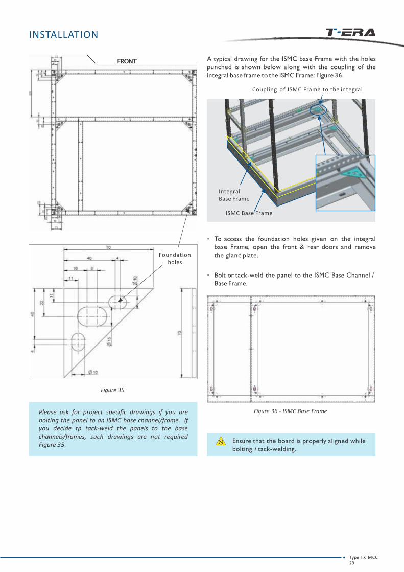
INSTALLATION
FRONT
Foundation holes
Figure 35
• To access the foundation holes given on the integral
base Frame, open the front & rear doors and remove
the gland plate.
• Bolt or tack-weld the panel to the ISMC Base Channel /
Base Frame.
Figure 36 - ISMC Base Frame
Ensure that the board is properly aligned while
bolting / tack-welding.
Please ask for project specific drawings if you arebolting the panel to an ISMC base channel/frame. Ifyou decide tp tack-weld the panels to the basechannels/frames, such drawings are not requiredFigure 35.
A typical drawing for the ISMC base Frame with the holes
punched is shown below along with the coupling of the
integral base frame to the ISMC Frame: Figure 36.
Coupling of ISMC Frame to the integral
Integral Base Frame
ISMC Base Frame
Type TX MCC29

INSTALLATION
CONNECTION OF TRANSPORT UNITS AND BUSBARS
1. For access to the horizontal busbars, remove top plates
and hoods (if provided) by removing all the bolts
provided on the top Figure 37.
2. Remove the fish plates provided on the right side of the
busbar to connect it with subsequent TUs placed
sequentially.
3. Clean the fishplates with a wire brush. Wipe them with
a soft, dry cloth and then immediately apply contact
grease on them. Hindustan Petroleum, MPL (EXXON)/
Petroleum Jelly J. P. grade contact grease or equivalent
is recommended.
4. Bolt adjacent TUs together - holes are provided in the
gasketted side pillar. This should be done before joining
the busbars.
5. Join horizontal bus bars using the fishplates as shown in
Figure 38.
Figure 38 - Top plate
Figure 37 - Top plate
Ensure bus bars are properly aligned so that there
is no strain on any of the support insulators.
6. Tighten all electrical connections with a torque wrench
to the torque values as mentioned in table no. 5 Figure
39.
Figure 39 - Tightening of Busbar joints
Size of bolt Torque in m.kg
Table No. 5
Thread
(Boltsize)
Kgf
m
Nm
Socke
t No.
(mm)
Normal Bolt
(Grade:4.8)
High Tensile
Norm
al Bolt Bolt
(Grade: 8.8) (Grade: 4.8)
HighTensile
Bolt
(Grade:8.8)
M6 0.38 1.05 3.7 10.29 11/10
M8 0.85 2.5 8.3 24.51 13/12
M10 1.88 4.7 18.8 46.09 17/16
M12 3.2 6.5 31.38 63.74 19/18
For aluminum bus bar system normal torque to be applied even if the bolt is HT. HT torque values are applicable
only for hole less bus bar joints.
Type TX MCC30

INSTALLATION
Figure 41 - MCC - MCC Earthbar Coupling
7. Join the auxiliary busbars by joining the auxbus fish plate
provided for the same in the left side TU Figure 40.
CONNECTION OF EARTHBARS
MCC-MCC
1. For single front panels, open the rear door of the panel to
access the horizontal earthbar.
2. In case of a back to back arrangement, open the cable
alley to access horizontal earthbar.
3. Remove the fishplate provided on left hand side TU to
connect it with subsequent TUsplaced sequentially.
4. Join the earth bars using the fishplate provided and check
correctness.
5. Tighten the connection with a torque wrench to the
torque values as mentioned in Table no. 5.
PCC-MCC
1. Open the rear door of the PCC.
2. Remove the fishplate provided at the end of horizontal
earthbar at the bottom.
3. Join the earthbar of PCC with the already extended MCC
earthbar using the fishplate.
4. Tighten the connection with a torque wrench to the
torque values as mentioned in Table No.5.
Figure 42 - PCC - MCC Earthbar Coupling
PCC HORIZONTAL EARTHBAR
MCC HORIZONTAL EARTHBAR
Figure 40 - Auxbus joining
Type TX MCC31

INSTALLATION
POWER CABLE TERMINATION
Power cable routing & dressing in cable alley chamber:
• Step 1: Branch out the cables (in case of multicore cables)
just after the gland plate at the bottom (in case of bottom
cable entry)
This will ease the flexibility required for fool-proof
termination
• Step 2 : By approximation, estimate the length of the
cable required to terminate the cable with required
bending radius (approx. 12 times the outer radius of the
cable as shown in Detail B, C, D)
• Step 3 : Take the branched out cables to the respective
feeder through the side walls of the cable alley as shown
in figure 44.
• Step 4 : Make the required curvature depending on the
type adaptor used for the feeder. Refer Termination of
Power Cables section.
• Step 5 : Adequately tie the cables with cable ties in the
cable bracket provided on the sides of the cable alley
Lug termination at the power terminal to be done only
after cable routing & dressing.
• Step 6 : *Using appropriate hardware and lug & with the
required torque value, tighten the cables to the respective
terminals, Refer table no. 6 (ensure the cable's stress /
weight is not transferred to the terminals).
*Hardware selection should be according to the
specification of Lug manufacturer/ supplier.
Figure 43 - Rear Cable Entry (Side View). Cables branching out though the side walls of cable alley.
Datail F
Datail G
Datail H
Cables to be tied to the cable bracket on the side walls of cable alley
Figure 44 - Side Cable Entry (Front View) Cables tied to cable bracket present on the sides of cable alley
All cables to be tied to cable bracket present on the sides of cable alley
Detail A
Detail B
Detail C
Detail D
Detail E
Ensure no cables are free hanging.
All cable wires should be supported appropriately and rigidly on the cable brackets.
Ensure cables are at a safe distance (min 50 mm)from liveparts.
Ensure bus bars are properly aligned so that thereis no strain on any of the support insulators.
Use of copper wires/cables is recommended forcontrol circuitspurposes.
Oblong holes are provided for Aluminiumfishplate joints. Extra drilling on the bus-bars/fishplates should be avoided.
Type TX MCC32

INSTALLATION
TERMINATIONS OF POWER CABLES
Power cables routed from cable chamber are connected to
feeder’s power contacts through lugs. Below instruction are
for all types of cable entries and terminations.
• Cable routing method to be followed in all the cases
• Cable clamp brackets are fixed at the same level as their
respective feeder so as to hold the cables rigidly.
• According to side and top cable entry and link
arrangement, chose one from below options and follow
the steps.
There are 2 types of lug termination in TX .This is based of
the rating of the feeder and cable size (No of runs of
cable/phase and Sq.mm of cable). The following are the
types
1. Direct termination - Lug is directly terminated on the
outgoing power contacts of the feeder.
2. Adaptor Termiantion - Adaptors are provided on the
power terminals and lug termination is done on the
adaptors
1. Direct Termination
There 4 types of direct cable termination SCE and 1 in RCE.
Side Cable Entry (Top/Bottom)
1. 400A contact direct termination -Refer Detail C
No. of runs of power cable possible per phase :2 (front &
back)
*M12 bolt to be used for lug termination
## The contacts encircled must not be tilted / misaligned /
stressed due to cable weight after termination.
2. 250A contact direct termination -Refer Detail C No. of
runs of power cable possible per phase :1 (front only)
*M12 bolt to be used for lug termination
3. 135A contact direct termination -Refer Detail D
No. of runs of power cable possible per phase: 2 (front &
back)
*M6 bolt- lug termination -without extension link
*M8 bolt- lug termination -with extension link
4. 135A contact direct termination - Refer Detail E & ETop
View
No. of runs of power cable possible per phase: 2 (front &
back)
*M8 bolt to be used for lug termination
Detail C
Phase Barrier
LUG Termination in front and back ofPower terminal (2/Phase)- only for 400A
LUG Termination infront only (1/Phase)for 250A
## CONTACT ALIGNMENT
Detail D
Contact alignment#
LUG Termination without extension link
Phase Barrier
LUG Termination with extension link
Detail E
Phase Barrier
Contact alignment#
Detail E - Top View
LUGTermination
Type TX MCC33

INSTALLATION
2. Adaptor Termination
Side Cable Entry (Top/Bottom)
1. Refer Detail A
No. of runs of power cable possible per phase: 3
*M12 bolt to be used for lug termination
2. Refer Detail B
No. of runs of power cable possible per phase: 2
*M12 bolt to be used for lug termination
Detail H
Rear Cable Entry
5. Refer detail H
No. of runs of power cable possible per phase: 2
*M12 bolt to be used for lug termination
LUG Termination
Phase Barrier
Detail A
LUGTermination
LUG Termination in front and back
Detail B
Rear Cable Entry (Top/ Bottom)
3. No. of runs of power cable possible per Phase: 3
*M12 bolt to be used for lug termination
Refer Detail F
Detail F
LUGTermination
Phase Barrier
Detail G
4. No. of runs of power cable possible per phase:2
M12 bolt to be used for lug termination
Refer Detail G
LUG Termination
Phase Barrier
Type TX MCC34

INSTALLATION
SIC CABLE TERMINATION
1. All cables to be unprepared (lugless) -strip length 12mm±
1mm (Caution: termination with lug will either cause
damage to terminals or loose terminations)
2. Cable termination capacity: 1:1.5 sq.mm / 1:2.5 sq.mm
only per terminal
3. For operating the SIC terminal for termination only L&T
supplied tool to be used (Caution: any other tool will
cause damage to the SIC contacts)
4. Ensure the cable is dressed with cable ties and the stress
of the cable doesn't affect the SICs free movement
Pictorial Representation of procedure to be followed for termination of control wires on SIC. The same sticker is applied inside your switchgear assembly as well.
PROCEDURE TO BE FOLLOWED FOR FIELD CONTROL WIRES TERMINATION ON SIC
Ter No: 10 Ter No: 20 • The SIC which is mounted on the cable alley is suitable forLUG LESS TERMINATION
• SPECIAL TOOL to be used for SIC TERMINATION• The tool will be supplied as a loose item in a separate box
CAUTION along with each switchboard
SPECIAL TOOL
Ter No: 11
Ter No: 1
STEP 1
a)Wire to be stripped using wire stripper up to 12+1 mm
12+1 mm
b)The wire must be multi
stranded
c)Do not use wire cutter for stripping the wires
STEP 2
All wires strands to be twisted together
STEP 3
a)Special tool to be inserted in the respective SIC terminal (as shown in photo) cavity
and press it.
b)Wire to be inserted on therespective SIC terminal as per
scheme
STEP 4
a)Remove the SIC special tool from SIC
b)Following self check to
be performed after the termination.
(i) Termination strength
(ii) No strands out
Type TX MCC35

INSTALLATION
Figure 45 - Control Cable terminals
Tightening torque values have been provided in Table No.5
on page No. 30.
Follow the following steps for removal of SICs for re-wiring / replacement:
1. Female SIC
Step 1 : Take the corresponding feeder to isolate position.
When the feeder is in isolated position, male SICs
gets disengaged from female SIC.
Step 2 : Open the cable alley door, without disturbing any
other feeder or Power cable termination follow
the below steps
Step 3 : Remove the SIC covers (1).
Step 4 : Unscrew the bottom SIC screws (7 & 8)
Step 5 : Unscrew the bottom SIC bracket's (2) hardwares
(4, 5, & 6)
Step 6 : Unscrew the female SICs (3) top screws
Step 7 : Plug out all the terminals &Remove the female SICs
(3)
2. MALE SIC
Step 1 : Takethe feeder out of the boards
Step 2 : Place it on a table
Step 3 : With the mechanism racking handle, take the
feeder to serviceposition (Ref fig 2.2)
Step 4 : Unscrew (10) the male SIC (9) (Ref fig 2.3)
Step 5 : Plug out all the terminals and take the SIC out
Follow the following steps for fixing SICs:
Detail A - Female SIC Removal
1
45
6
7
3
2
8
Type TX MCC36

INSTALLATION
Male SIC Fixing in Module
10
9
MALE SIC FIXING
Step 1 : Takethe feeder out of the boards.
Step 2 : Place it on a table.
Step 3 : With the mechanism racking handle, take the
feeder to serviceposition (Ref fig 2.2).
Step 4 : Mount the male SIC (ensure terminal numbering
(1- 20) matches with female SIC) outside the slot of
SIC holder as shown in detail f.
Step 5 : Fix the SIC using hardwares (9)& (10).
FEMALE SIC FIXING
Step 1 : Fix the top SIC bracket (8) alone using hardwares
(4), (5)& (6).
Step 2 : Take the female SIC (3), (ensure terminal
numbering (1-20) matches with male SIC) and fix
the bracket between the slot as shown in detail g.
Step 4 : Fix female SIC using harwares (7) & (8).
Step 3 : Fix the bottom SIC bracket (8).
Step 4 : Terminate all the cables on the SIC as per scheme.
Step 5 : Carry out SIC alignment (refer SIC alignment sop).
Step 6 : Replace the SIC covers (1).
Follow the following steps for SIC Alignment:
Step 1 : Remove the SIC covers and loosen the bracket
hardwares - 4 nos of screws.
(caution :do not remove the hardware)
Step 2 : Take the corresponding feeder to test state slowly.
(caution : operate the racking handle slowly & do
not damage the SIC pins)
Step 3 : Lift up the bottom SIC bracket and align both male
and female SIC. (caution : continue to hold the
bracket from bottom)
Step 4 : Tigheten the hardware by continuing to hold the
SIC bracket from bottom.
Step 5 : The SICs are aligned. Operate the module from
isolate to test & then to service.
Step 6 : For any issues, refer SIC trouble shooting page 38.
Detail C - Female SIC Removal
Detail D
See detail D
SIC tool supplied by L&T
Cable termination circular slots
Tool insertion square slots
Lift up the botom bracket along with SIC
Type TX MCC37

INSTALLATION
SIC TROUBLE SHOOTING
Type TX MCC38
S.No. PROBLEM POSSIBLE CAUSE ACTION
1 FEEDER is not racking from ISOLATE (I) position to TEST (T) position in door closed condition
The handle is not inserted properly
The Racking mechanism is not working
The female SIC holding bracket in cable aley is bent / deformed
Cable stress on the female SIC / or on SIC Cover due to routing near sides of female SIC
The SIC alignment is not correct
The Male SIC is damaged
Insert the handle, press it and Turn the handle Clock-wise. Refer Page 53 for details
Racking mechanism need to be fixed
Replace the bracket if they are deformed, Repeat SIC alignment
Re-route the cabling near the Female SIC.
Ensure cable ties don't obstruct SIC free movement
Repeat SIC Alignment procedure
Replace Male SIC. Do SIC alignment
2 FEEDER is not racking from TEST (T) position to SERVICE(S) position
The Racking mechanism is not working
The O/G contact fixing support is loose
The O/G Contacts are misaligned / damaged
Racking mechanism need to be fixed
Check the tightness of the O/G Contact fixing support
Check Power cable termination instruction
3 FEEDER status indication Lamp not working
No control supply available
The male SIC is damaged
Loose termination
Indication lamp burn-out
Check control supply
Replace Male SIC. Repeat SIC aliment
Re-check termination. Refer SIC termination procedure
Replace indication lamp
4 Loose termination of SIC SIC termination tool not used
Lugs on cables are used for termination
SIC block damaged
Use the SIC special tool for termination
Use only bare condctor stripped to 12mm length for termination
Replace damaged SIC. Repeat SIC alignment
Table No. 6

INSTALLATION
Interpanel wiring
1. Wiring is through the horizontal wire-way at the top
along the auxiliary bus.
2. For wiring, separate terminals are provided in the left
hand side of the right most TU which are named XS-YY
(X - terminal no. and YY - panel no. (01,02,03 etc.)). The
wire bunch to be connected to these terminals is in the
left-hand side transport unit. The wires have ferrules with
the terminal no. and should be connected their respective
terminals. The no. of terminals and no. of wires to be
connected are equal.
For example, consider the panels and transport units shown
in the sketch. The transport unit (TU) consists of panel 1F
and 2F, while TU-2 consists of panel 3F and 4F. The terminals
named 1,2,3... -XS03 are mounted in panel 3F as shown in
the figure. The mounted terminals are connected to their
respective equipment in panels 3F and 4F. The wires going
from TU-1 to TU-2 are bunched and kept with panel 2F. The
wire which is to be connected to terminal 1 of panel 3F will
have a ferrule marked 1XS03 at the end of it and will be kept
in 2F.
Figure 46 - Interpanel Wiring
T.U.-1 T.U.-2
1F 2F 3F
Terminals names 1,2,3...XS03
Wire bunch to be connected having corresponding ferrules marked 1,2,3...XS03
4F
Horizontal wirewayShipping section terminals
INSTALLATION OF LOOSE MATERIAL
Metering and control devices:
1. Unpack the metering and control devices (like meters and
relays) if they were sent as separate packages.
2. Position the device in the apt cut-out or base plate
provided.
3. Wire them as per the scheme drawing provided.
4. Refer product inserts for further details about thedevice.
5. Carry out the settings of magnitude and time delay (if
any) for the installed protective and control devices as
shown in scheme drawing and MBOM (Master Bill of
Materials).
6. Place the terminal covers properly to adhere to stated
ingressprotection (IP) level.
7. Check alignment of operating handles for all switches.
8. While dispatching the switchboard, secondaries of all
current transformers are shorted. Remove these shorting
cables while connecting relays/meters and store them
separately Figure 48.
Figure 47 - Relay Mounting on Panel
9. Ensure again that all doors are closed and no connection
is left loose.
Type TX MCC39

Modules
1. Modules are not bolted inside the panel.
2. Open the compartment door.
3. Takethe module out. Refer Page No.38 & 39
4. Remove the padding provided (for transit) at the sides of
the module.
5. Insert the module inside the panel and bring it to
service position.
Control Transformers
1. Unpack the Control Transformer.
2. Open the compartment door in which the Control
Transformer is to be installed.
3. Bolt the Control Transformer to the base plate Figure 49.
4. Terminate the primary and secondary wires of the
transformer on the respective terminals.
INSTALLATION
Figure 48 - Control Transformer Mounting on Panel
Figure 49 - Installation of Control Transformer
5. The primary wire has a ferrule with capital letters while
that of the secondary is with unicase Figure 50.
Type TX MCC40
6. Check the connections and tighten the bolt.

INSTALLATION
End Cover
Figure 50 - Extension of Panel
INSTALLING AN EXTENSION PANEL
Tojoin an extension panel to your existing TX,
1. Remove the end cover of existing TX at the joining end
Figure 51.
2. Follow instructions listed in ‘Connection of TUs’ under
Installation on Page No. 24.
Ensure that both power and control circuits are switched off before taking the end cover off the TU.
3. Necessary busbars / fishplates are supplied with the
extension panel.
4. Place the end cover on the newly added panel.
Type TX MCC41
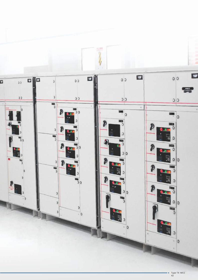
Type TX MCC42

SITE TESTING
Type TX MCC43
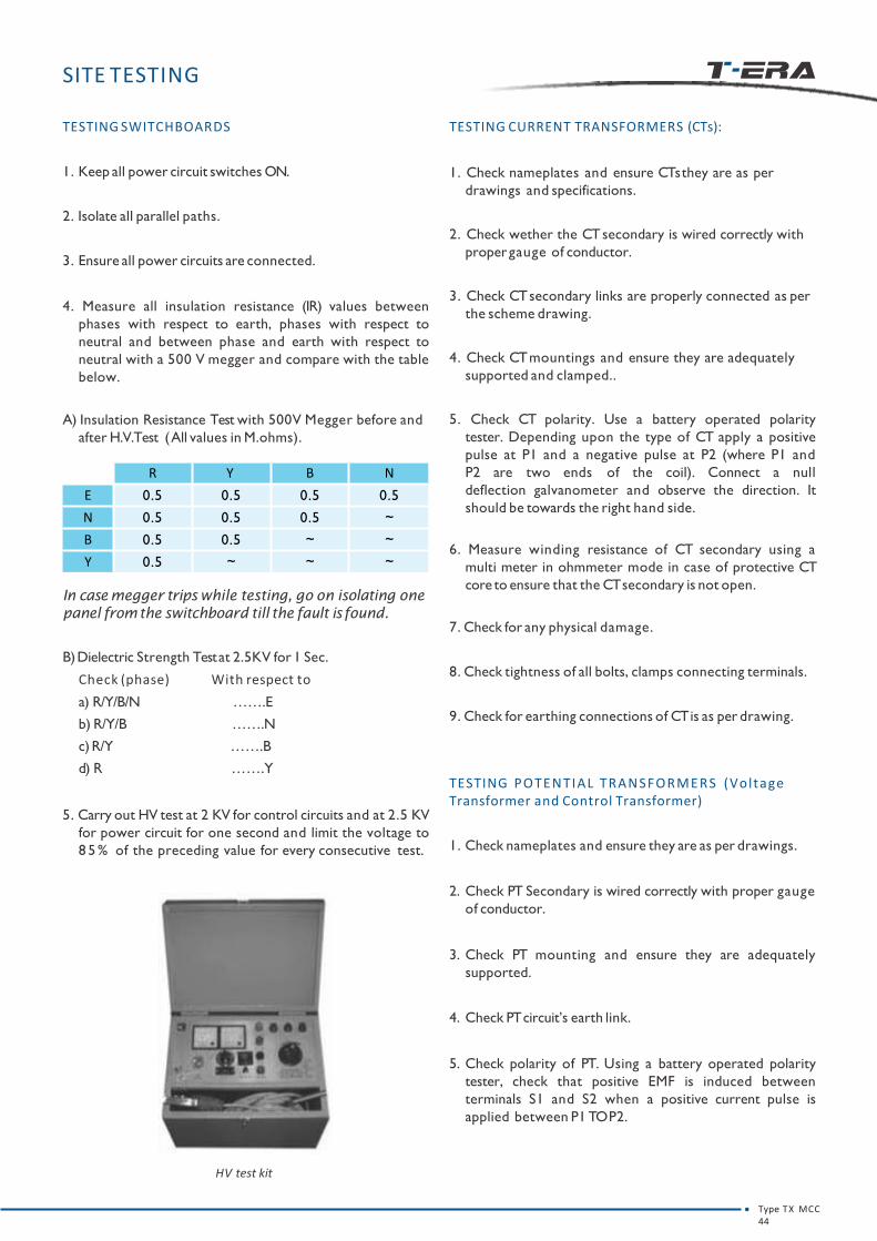
SITE TESTING
TESTING SWITCHBOARDS
1. Keep all power circuit switches ON.
2. Isolate all parallel paths.
3. Ensure all power circuits are connected.
4. Measure all insulation resistance (IR) values between
phases with respect to earth, phases with respect to
neutral and between phase and earth with respect to
neutral with a 500 V megger and compare with the table
below.
A) Insulation Resistance Test with 500V Megger before and
after H.V.Test (All values in M.ohms).
In case megger trips while testing, go on isolating one
panel fromthe switchboard till the fault isfound.
B)Dielectric Strength Testat 2.5KV for 1 Sec.
Check (phase)
a) R/Y/B/N
b) R/Y/B
c) R/Y
d) R
With respect to
…….E
…….N
…….B
…….Y
5. Carry out HV test at 2 KV for control circuits and at 2.5 KV
for power circuit for one second and limit the voltage to
8 5 % of the preceding value for every consecutive test.
TESTING CURRENT TRANSFORMERS (CTs):
1. Check nameplates and ensure CTs they are as per
drawings and specifications.
2. Check wether the CT secondary is wired correctly with
propergauge of conductor.
3. Check CT secondary links are properly connected as per
the scheme drawing.
4. Check CT mountings and ensure they are adequately
supported and clamped..
5. Check CT polarity. Use a battery operated polarity
tester. Depending upon the type of CT apply a positive
pulse at P1 and a negative pulse at P2 (where P1 and
P2 are two ends of the coil). Connect a null
deflection galvanometer and observe the direction. It
should be towards the right hand side.
6. Measure winding resistance of CT secondary using a
multi meter in ohmmeter mode in case of protective CT
core to ensure that the CTsecondary is not open.
7. Check for any physical damage.
8. Check tightness of all bolts, clamps connecting terminals.
9. Check for earthing connections of CTis as per drawing.
TESTING POTENTIAL TRANSFORMERS (VoltageTransformer and Control Transformer)
1. Check nameplates and ensure they are as per drawings.
2. Check PT Secondary is wired correctly with proper gauge
of conductor.
3. Check PT mounting and ensure they are adequately
supported.
4. Check PTcircuit’s earth link.
5. Check polarity of PT. Using a battery operated polarity
tester, check that positive EMF is induced between
terminals S1 and S2 when a positive current pulse is
applied between P1 TOP2.
HV test kit
Type TX MCC44
R Y B N
E 0.5 0.5 0.5 0.5
N 0.5 0.5 0.5 ~
B 0.5 0.5 ~ ~
Y 0.5 ~ ~ ~

SITE TESTING
6. Check ratio of all cores. Conduct ratio test by applying
1 phase 240V across the primary. Note voltage at
secondary. Calculate the ratio, tabulate and compare the
value with the nameplate values.
7. Measure winding resistance.
8. Check for any physical damage.
9. Check tightness of all connecting terminals.
10. Check for the earthing of PTas per the drawing.
TESTING METERS AND TRANSDUCERS:
1. Inspect all meters and transducers for proper mounting
and for any damage.
2. Testwith calibrated meters.
3. Check CT and VT connections with particular reference to
their polarities for power type meters wherever they are
provided.
4. Check for the earthing of meters and transducers as per
the drawing.
TESTING RELAYS:
1. Inspect for propermounting and for any breakage.
2. Ensure gagging on all the moving parts is removed.
3. Check nameplate details as per specification.
4. Set the relay as per setting sheet, (protection co-
ordination) and check for its operation at set values.
TESTING CONTROL CIRCUITS
1. Check the insulation of the auxiliary circuit before testing
the control circuitry using megger.
2. Check that fuses are fitted in the main and auxiliary circuit
and that ratings are appropriate for the circuit.
3. Perform the electrical continuity test on the control circuit
for any lapse in connection.
4. Check for the phase sequence of the incoming supply.
5. Repeat the test as stated in the FAT (Factory Acceptance
Test) for all the feeders existing.
6. Check the settings of overload relays and other
protection relays. During commissioning checks, set the
overload relay to the minimum value. Setting of the relay
should be as per setting chart supplied by L&T.
CLOSING,TRIPANDEMERGENCYCIRCUITS
1. Close the incomer and check the functionality of the
closing feeder as per scheme drawing provided.
2. Check the indication corresponding to the feeder.
3. Carry out the test for tripping as per FAT (Factory
Acceptance Test)that is unique for every switchboard.
4. Check the Emergency push buttons and other trip
mechanisms using scheme drawing provided.
Perform the test as per SAT (Site Acceptance Test) if
provided. (Note that SAT is provided on request.)
Type TX MCC45
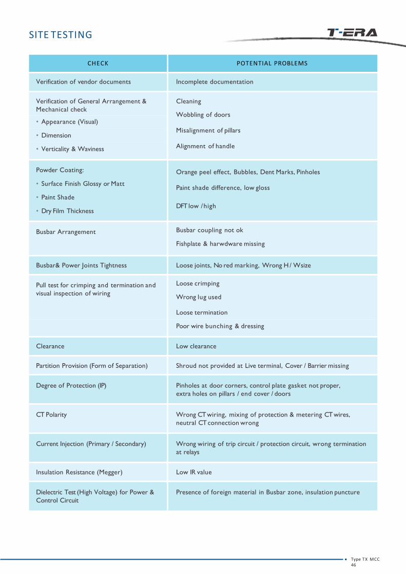
CHECK POTENTIAL PROBLEMS
Verification of vendor documents Incomplete documentation
Verification of General Arrangement &
Mechanical check
Cleaning
Wobbling of doors
Misalignment of pillars
Alignment of handle
• Appearance (Visual)
• Dimension
• Verticality & Waviness
Powder Coating:
• Surface Finish Glossy or Matt
• Paint Shade
• Dry Film Thickness
Orange peel effect, Bubbles, Dent Marks, Pinholes
Paint shade difference, low gloss
DFT low /high
Busbar Arrangement Busbar coupling not ok
Fishplate & harwdware missing
Busbar& Power Joints Tightness Loose joints, No red marking, Wrong H / Wsize
Pull test for crimping and termination and
visual inspection of wiring
Loose crimping
Wrong lug used
Loose termination
Poor wire bunching & dressing
Clearance Low clearance
Partition Provision (Form of Separation) Shroud not provided at Live terminal, Cover / Barrier missing
Degree of Protection (IP) Pinholes at door corners, control plate gasket not proper,
extra holes on pillars / end cover / doors
CT Polarity Wrong CT wiring, mixing of protection & metering CT wires,
neutral CT connection wrong
Current Injection (Primary / Secondary) Wrong wiring of trip circuit / protection circuit, wrong termination
at relays
Insulation Resistance (Megger) Low IR value
Dielectric Test (High Voltage) for Power &
Control Circuit
Presence of foreign material in Busbar zone, insulation puncture
SITE TESTING
Type TX MCC46

PRE-ENERGISING
CHECKS
Type TX MCC47

PRE-ENERGISING CHECKS:
Ensure the following checks are carried out before energizing:
Sr.No. Check Point OK
1 Overall Appearance & surface finish
2 Panel is on a level surface
3 Room ventilation
4 Fire Extinguisher
5 Rubber mats of grade 1100 V
6 Loose items fitted
7 Verification as per BOM and GA
8 T ightness of busbar Joints
9 Wiring check as per scheme drawings
10 Phase sequence / Polarity check
11 CT & PT ratio check (on Sampling)
12 Insulation Resistance
13 High Voltage Test (Power Circuit)
14 High Voltage Test (Control Circuit)
15 All doors closed
Type TX MCC48

COMMISSIONING
OFF ON
Type TX MCC49

COMMISSIONING
be checked beforeGeneral parameters which must
commissioning the switchboard are :
• Control andIndication
• Remote Operation (if any)
• Electrical Interlocks (if any)
Figure 51 - Energised Panel
Congratulations!
Your switchboard has now been commissioned.
Type TX MCC50

OPERATION
Type TX MCC51

OPERATION
FRACTIONAL MODULES:
Racking-in:
1. Prior to insertion of the module, ensure that the position
indicator of the module is showing ‘isolated’ position. If
not, bring it to ‘isolated’ position using the camlock key
Figure 53.
2. Insert the module by racking it and moving it in, while
keeping the key turned. Bring it to service position by
pushing the racking handle twice Figure 54.
Racking-out:
1. Turn the key anticlockwise until the position indicator
indicates isolated (I)position.
2. Bring the module to draw out position using the camlock
key and pull the module out.
Refer Table No. 7 for position / condition of Knob, ROM
(Rotary Operating Mechanism) and Handle, power
contacts and SICs of fractional width modules during the
Rack-in and Rack-out process.
Figure 53 - Service-Test-Isoalted-Withdrawable Position of the Fractional Module
Figure 52 - Camlock key
Table No. 7
SERVICETEST
ISOLATEDDRAWOUT
KNOB POSITION
ROM POSITION
HANDLE POSITION
POWER CONTACTS
SIC
SERVICE (S)- OFF OR- O
N
CONNECTED CONNECTED
TEST (T) - OFF DISCONNECTED CONNECTED
ISOLATION (I) - OFF DISCONNECTED DISCONNECTED
DRAWOUT - OFFSAME AS IN ISOLATION
DISCONNECTED DISCONNECTED
Type TX MCC52

Figure 55 - Full width module in Test position
OPERATION
Figure 56 - Full width module in Isolated position
FULL WIDTH MODULES
1. Prior to insertion of the module, ensure that the position
indicator of the module is showing ‘isolated’ position
Figure 22. If not, bring it to ‘isolated’ position using the
racking handle.
2. To rack in, Insert the handle in the slot provided on the
front of the module Figure 58.
• Press and rotate clockwise to move forward (I->T->S)
Figure 55.
• Rotate the handle through 90 degree in clockwise
direction to bring it to Isolated position Figure 57.
3. To rack out, follow the sequence mentioned above in
an anti-clockwise direction from service to isolated.
The handle cannot be taken out in any
intermediate position.
KEEPING THE HANDLE PRESSED IN, ENSURE THIS GAP IS ZERO AND THEN ROTATE.
Figure 58 - Lifting of Full width module
Figure 57 - Position for handle insertion
4. Towithdraw the module, lift the strip and use the lifting
rod provided to take it out Figure 59.
Lifting Rod
Figure 54 - Full width module in Service position
• After a 90 degree turn from service position, the module
will come to the test position and the handle can be taken
out. Figure 56.
Type TX MCC53

Type TX MCC54

MAINTENANCE
Type TX MCC55

MAINTENANCE
PRECAUTIONS
1. Switch off the incoming power supply before removing
top plates and side covers. Isolate incoming power
supply.
2. For safety of personnel, while working on bus bars,
provide temporary earthing using a metallic chain/strip
near the work place. Remove this earthing only after the
job is completed.
3. Switch off the control supply. Isolate remote control
voltage sources.
4. Measure busbars voltage to ensure that bus bars are
de-energized.
5. Ensure that only qualified personnel are permitted to
use the defeat mechanism to gain access to an
energised compartment.
6. Do not attempt to withdraw the unit or disconnect any
terminations when the defeat mechanism has been
used to open a compartment door.
7. Current transformer primaries must not be energised
when secondaries are open circuited.
8. Short all CTsecondaries.
9. In case of shutdown on only one feeder, padlock the
power switch in OFFposition.10. After maintenance, if TX is going to be de-energised for
a longer period, switch on the panel space heaters to
prevent moisture condensation on the cables/
insulators.
ROUTINE CHECKS
Carry out the following checks regularly:
1. Inspect all devices every two months to ensure that the
equipment is in properworking order.
2. Check tightness of bolted joints (mainly Busbar)
Figure 60.
- prior toenergisation
- six months after load is connected
- one year after the second check and then once a year
Figure 59 - Tightening of Busbar & Dropper Joint
3. Inspect all wiring for wear and cuts every two months.
4. Look for signs of wear of the silver plating on the stab-in
contacts and on the contacts fixed to the dropper at the
point where the stab-in contacts engage with the fixed
contacts. The plating is part of the protection against
corrosion when module is outside the panel.
5. Clean and lubricate the stab-in contacts once a year
with HPMPL (EXXON)grease.
6. Remove burnt out fuses if any.
7. Check terminal block contacts for loose connections.
8. Examine indicating lamps and replace if required.
9. Ensure all safety interlocks are functional and in proper
working order every two months.
10. Look for indications of overheating, sparking or
insulation breakdown on the busbars.
11. Inspect power and control contacts. Replace worn out
contacts (refer the section replacement of power
contacts on Page No. 28)
12. Inspect all auxiliary and control circuits every two
months for desired functioning.
13. Grease racking screw and telescopic rails at least once a
year. Use grease 'HP-LETHON-2' or 'SYNTHOLUBE-20 of
HJ Leach & Co.
14. Ensure that the earth wires are connected to the main
earth bar (except electronic device earthing).
15. Ensure no tools or loose materials are left inside the TX
as these can cause faults.
16. Keep the switchboard free of dust. Use a vacuum
cleaner to remove the dust.
Figure 60 - Tightening of Busbar Joints
Do not operate equipment whose arc chutes are removed.
Type TX MCC56
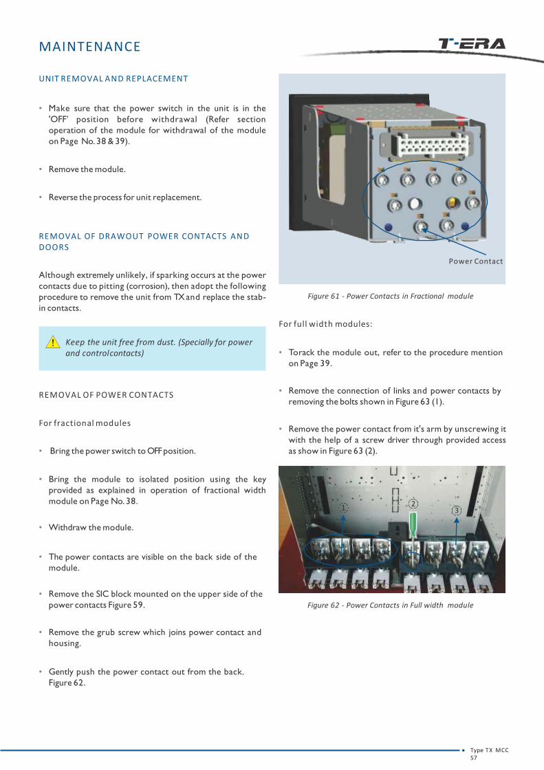
MAINTENANCE
UNIT REMOVAL AND REPLACEMENT
• Make sure that the power switch in the unit is in the
'OFF’ position before withdrawal (Refer section
operation of the module for withdrawal of the module
on Page No. 38 & 39).
• Remove the module.
• Reverse the process for unit replacement.
REMOVAL OF DRAWOUT POWER CONTACTS AND DOORS
Although extremely unlikely, if sparking occurs at the power
contacts due to pitting (corrosion), then adopt the following
procedure to remove the unit from TXand replace the stab-
in contacts.
Keep the unit free from dust. (Specially for power and controlcontacts)
REMOVAL OF POWER CONTACTS
For fractional modules
• Bring the power switch to OFFposition.
• Bring the module to isolated position using the key
provided as explained in operation of fractional width
module on Page No. 38.
• Withdraw the module.
• The power contacts are visible on the back side of the
module.
• Remove the SIC block mounted on the upper side of the
power contacts Figure 59.
• Remove the grub screw which joins power contact and
housing.
• Gently push the power contact out from the back.
Figure 62.
Figure 61 - Power Contacts in Fractional module
Power Contact
For full width modules:
• To rack the module out, refer to the procedure mention
on Page 39.
• Remove the connection of links and power contacts by
removing the bolts shown in Figure 63 (1).
• Remove the power contact from it's arm by unscrewing it
with the help of a screw driver through provided access
as show in Figure 63 (2).
Figure 62 - Power Contacts in Full width module
1 23
Type TX MCC57
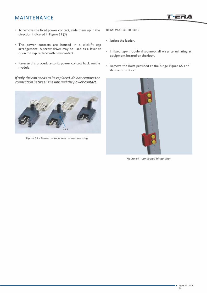
MAINTENANCE
• Toremove the fixed power contact, slide them up in the
direction indicated in Figure 63 (3)
• The power contacts are housed in a click-fit cap
arrangement. A screw driver may be used as a lever to
open the cap replace with new contact.
• Reverse this procedure to fix power contact back on the
module.
If only the capneeds to be replaced,do not removethe
connection between the link and the power contact.
Cap
Figure 63 - Power contacts in a contact housing
REMOVAL OF DOORS
• Isolate the feeder.
• In fixed type module disconnect all wires terminating at
equipment located on the door.
• Remove the bolts provided at the hinge Figure 65 and
slide out the door.
Figure 64 - Concealed hinge door
Type TX MCC58

TROUBLE
SHOOTING
Type TX MCC59

On a live switchboard :
• Identify fault location using indicating lamps or
monitoring system.
• Check for availability of supply at SIC’s (Secondary
Isolating Contact or Draw-out terminals) connected to
auxiliary bus.
• Check if power switch/MCCB is in ‘ON’ position.
• Reset the relay orMCB after the fault has been cleared.
• Check if control MCB is ‘ON ‘after opening the
compartment door.
• If control fuse is used, check the health of the fuse.
Replace if necessary.
• Check whether terminations from field connections are :
1. Correctly terminated
2. Tight
TROUBLE SHOOTING
• Check whether inputs coming from the field are
functioningor not.
• Switch on control MCB/ control fuse, ensure interlocks
are active and turn on the feeder.
• If control MCB/ control fuse trips verify the field
terminations on the SIC.
• If control MCB/ control fuse has not tripped but the
module still fails to operate, then check the health of the
control circuit using a line tester.
• If the problem persists, check for component failure.
• After trouble-shooting ensure that the module is racked
in to service position.
If the problem persist,contact your nearest salesoffice
oremail your query to [email protected]
Type TX MCC60

RECOMMENDATIONS
1. Provide a small storage cabinet in every switchgear room
for:
• Tools like screw drivers, fuse pulling handle, chassis
racking handles.
• All reference drawings like General Arrangement
Drawing, Scheme drawing.
• Consumable spares like bulbs, fuses etc.
2. Do not use rewired HRC fuses. They may cause arcing or
explosions, leading to a fire.
Type TX MCC61
LIST OF FIGURES
Figure 1 - Floor mounted panel 03
Figure 2 - Different Compartments 04
Figure 3 - Double Deck arrangement of busbars 10
Figure 4 - Busbar Support 10
Figure 5 - Dropper Support 10
Figure 5.1 - Fully EnclosedDroppers 10
Figure 5.2 - Fully Enclosed Droppers(Topview) 10
Figure 6 - Auxbus Chamber 11
Figure 7 - 1 Quater (160 mm height) 12
Figure 8 - 2 Quater (320 mm height) 12
Figure 9 - 1 Half (160 mm height) 12
Figure 10 - 2 Half (320 mm height) 12
Figure 11 - 1 Full (160 mm height) 12
Figure 12 - 2 Full (320 mm height) 12
Figure 13 - 3 Full (480 mm height) 12
Figure 14 - Full width power switch padlocking 13
Figure 15 - Full width module padlocking 13
Figure 16 - Fractional module padlocking 13
Figure 17 - Door defeat interlock 13
Figure 18 - Safety shutter 13
Figure 19 - Earthing for full width module 13
Figure 20 - Earthing for fractional module module 14
Figure 21 - Power contacts 14
Figure 22 - Control plate 14
Figure 23 - SIC in full width module 14
Figure 24 - SICs in fractional module 15
Figure 25 - Module in Service position 15
Figure 26 - Module in Testposition 15
Figure 27 - Module in Isolated position 15
Figure 28 - Packing case Details 19
Figure 29 - Positioning of TUon truck 19
Figure 30 - Lifting Channel 20
Figure 31 - Chain marks on packed Tus 20
Figure 32 - Typical arrangements 27
Figure 33 - Tools 28
Figure 34 - Panel mounting on ISMC Base Channel/Base Frame 28
Figure 35 - Integral Base Frame 29
Figure 36 - ISMC BaseFrame 29
Figure 37 - Topplate 30
Figure 38 - Busbar joining 30
Figure 39 - Tightening of Busbar joints 30
Figure 40 - Auxbus joining 31
Figure 41 - MCC - MCC Earthbar Coupling 31
Figure 42 - PCC - MCC Earthbar Coupling 31
Figure 43 - Rear Cable Entry 32
Figure 44 - Side CableEntry 32
Figure 45 - Control Cable terminals 36
Figure 46 InterpanelWiring 39
Figure 47 - Relay Mounting on Panel 39
Figure 48 - Control Transformer Mounting on Panel 40
Figure 49 - Installation of Control Transformer 40
Type TX MCC62

LIST OF FIGURES
LIST OF TABLE
Type TX MCC63
Figure 50 - Extension of Panel 41
Figure 51 - Energised Panel 50
Figure 52 - Camlock key 52
Figure 53 - Service-Test-Isoalted-Withdrawable Position of the Fractional Module 52
Figure 54 - Full width module in Service position 53
Figure 55 - Full width module in Testposition 53
Figure 56 - Full width module in Isolated position 53
Figure 57 - Position for handle insertion 53
Figure 58 - Lifting of Full width module 53
Figure 59 - Tightening of Busbar & Dropper Joint 56
Figure 60 - Tightening of Busbar Joints 56
Figure 61 - Power Contacts in Fractional module 57
Figure 62 - Power Contacts in Full width module 57
Figure 63 - Power contacts in a contact housing 58
Figure 64 - Concealed hinge door 58
Table1 - Technical Data 05
Table2 - Panel Configuration 07
Table3 - Typical Auxiliary busbararrangement 11
Table4 - State of Power & Control Contacts in Various positions 15
Table5 - Size of bolt Torquein m.kg 30
Table6 - SIC TroubleShooting 38
Table7 - State of Power & Control Contacts in Various positions - Fractional width module 52

NOTE
Type TX MCC64

NOTE
Type TX MCC65
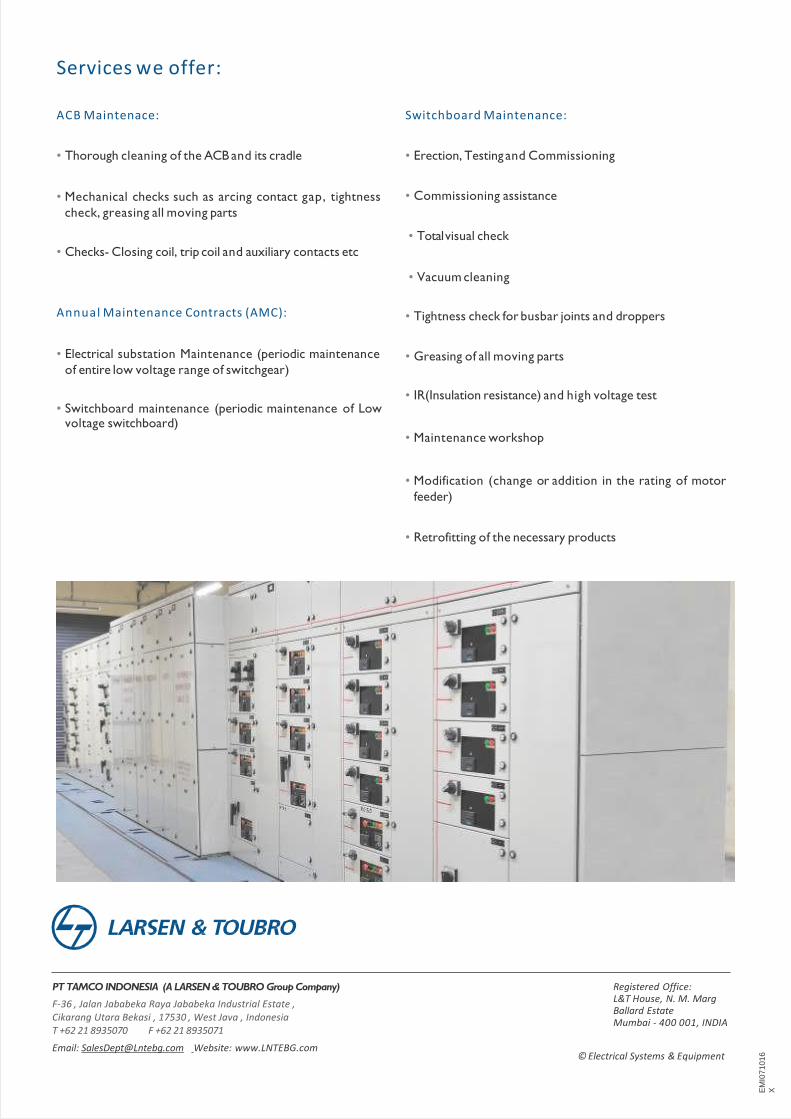
PT TAMCO INDONESIA (A LARSEN & TOUBRO Group Company)
F-36 , Jalan Jababeka Raya Jababeka Industrial Estate , Cikarang Utara Bekasi , 17530 , West Java , IndonesiaT +62 21 8935070 F +62 21 8935071
Email: [email protected] Website: www.LNTEBG.com© Electrical Systems & Equipment
Registered Office:L&T House, N. M. Marg Ballard EstateMumbai - 400 001, INDIA
ACB Maintenace:
• Thorough cleaning of the ACB and its cradle
• Mechanical checks such as arcing contact gap, tightness
check, greasing all moving parts
Annual Maintenance Contracts (AMC):
• Electrical substation Maintenance (periodic maintenance
of entire low voltage range of switchgear)
Switchboard Maintenance:
• Erection, Testing and Commissioning
• Commissioning assistance
• Totalvisual check
• Checks- Closing coil, trip coil and auxiliary contacts etc
• Vacuum cleaning
• Tightness check for busbar joints and droppers
• Greasing of all moving parts
• IR(Insulation resistance) and high voltage test• Switchboard maintenance (periodic maintenance of Low
voltage switchboard)• Maintenance workshop
• Modification (change or addition in the rating of motor
feeder)
• Retrofitting of the necessary products
Services we offer:
EM
I07
10
16
X