ltr description date approved - home - ams ... ltr description date approved prepared in accordance...
TRANSCRIPT
REVISIONS
LTR
DESCRIPTION
DATE
APPROVED
Prepared in accordance with ASME Y14.100 Source Control Drawing REV
PAGE
REV
PAGE
REV STATUS OF PAGES
REV
PAGES
PMIC N/A
PREPARED BY Ken R. Beymer
DESIGN ACTIVITY DEFENSE SUPPLY CENTER, COLUMBUS COLUMBUS, OH
Original date of
drawing
July 24, 2003
CHECKED BY Ken R. Beymer
TITLE SHIELDING BEAD, ELECTRONIC, CHIP, FERRITE, HIGH RELIABILITY
APPROVED BY Kendall A. Cottongim
SIZE
A
CODE IDENT. NO.
037Z3
DWG NO. 03024
REV
PAGE 1 OF 15
AMSC N/A 5950-E018 DISTRIBUTION STATEMENT A. Approved for public release; distribution is unlimited.
1. SCOPE
1.1 Scope. This drawing establishes the requirements for the screening of ferrite chip beads. Ferrite chip beads described in this document are manufactured and screened for high reliability applications. Ferrite chip beads described herein are capable of operation over a temperature range of -55°C to +125°C ambient including high vacuum environments.
1.2 Part or Identifying Number (PIN). The complete PIN shall be as follows:
03024 -001 P | | | | | | Drawing Dash number Impedance tolerance number (see table I) (see table II)
2. APPLICABLE DOCUMENTS
2.1 Government documents.
2.1.1 Specifications, standards, and handbooks. The following specifications, standards, and handbooks form a part of
this document to the extent specified herein. Unless otherwise specified, the issues of these documents are those listed in the issue of the Department of Defense Index of Specifications and Standards (DoDISS) and supplement thereto, cited in the solicitation (see 6.2).
STANDARDS
DEPARTMENT OF DEFENSE
MIL-STD-202 - Test Methods for Electronic and Electrical Component Parts. MIL-STD-1285 - Marking of Electrical and Electronic Parts.
(Unless otherwise indicated, copies of federal and military specifications, standards, and handbooks are available from
the Document Automation and Production Service, Building 4D (DPM-DODSSP), 700 Robbins Avenue, Philadelphia, PA 19111-5094.)
2.2 Non-Government publications. The following document(s) form a part of this document to the extent specified
herein. Unless otherwise specified, the issues of the documents that are DoD adopted are those listed in the issue of the DoDISS cited in the solicitation. Unless otherwise specified, the issues of documents not listed in the DoDISS are the issues of the documents cited in the solicitation (see 6.2). AMERICAN NATIONAL STANDARDS J-STD-004 - Requirements for Soldering Fluxes. J-STD-006 - Requirements for Electronic Grade Solder Alloys and Fluxed and Non-Fluxed Solder Solders for Electronic Soldering Applications. (DoD activities may obtain copies of American National Standards from the Standardization Document Order Desk, 700 Robbins Avenue, Building 4D, Philadelphia, PA 19111-5094. The private sector and other Government agencies may purchase copies from the Institute for Interconnecting and Packaging Electronic Circuits (IPC), 7380 N. Lincoln Avenue, Lincolnwood, IL 60646-1776.)
DEFENSE SUPPLY CENTER, COLUMBUS SIZE CODE IDENT NO. DWG NO.
COLUMBUS, OHIO A 037Z3 03024 REV PAGE 2
AMERICAN NATIONAL STANDARDS INSTITUTE (ANSI) ANSI/EIA-595 - Visual and Mechanical Inspection Multilayer Ceramic Chip Capacitors. ANSI/NCSL Z540-1 - Calibration Laboratories and Measuring and Test Equipment - General Requirements. ISO 10012-1 - Quality Assurance Requirements for Measuring Equipment - Part 1: Meterological Confirmation System for Measuring Equipment. (Applications for copies should be addressed to the American National Standards Institute (ANSI), 11 West 42nd Street, New York, NY 10036-8002.) AMERICAN SOCIETY FOR TESTING AND MATERIALS (ASTM) ASTM E595 - Standard Test Method for Total Mass Loss and Collected Volatile Condensable Materials from Outgassing in a Vacuum Environment. (Applications for copies of ASTM publications should be addressed to the American Society for Testing and Materials (ASTM), 100 Barr Harbor Drive, West Conshohocken, PA 19428-2959.) INTERNATIONAL ELECTROTECHNICAL COMMISSION (IEC) IEC 60068-2-21 - Robustness of Terminations and Integral Mounting Devices. Applications for copies should be addressed to the Customer Service Center (CSC), International Electrotechnical Commission, 3, rue de Varembe’, 1211 GENEVA 20, Switzerland.) (Non-Government standards and other publications are normally available from the organizations that prepare or distribute the documents. These documents also may be available in or through libraries or other informational services.) 2.3 Order of precedence. In the event of a conflict between the text of this document and the references cited herein, the text of this document takes precedence. Nothing in this document, however, supersedes applicable laws and regulations unless a specific exemption has been obtained.
3. REQUIREMENTS
3.1 Design and Construction. 3.1.1 Dimensions and configurations. Dimensions and configuration shall be as specified in figure 1 and table I. 3.1.2 Terminals. The terminations shall be covered with tin/lead coating. The tin content of the coating shall not exceed 97%. Gold terminations are optional. 3.1.3 Body. The body shall be comprised of a ferrite-based material that is substantially devoid of air.
3.2 Impedance. The impedance values for ferrite chip beads shall be as specified in table I. Impedance shall be measured in accordance with 4.6.19. 3.3 Maximum Current Rating. The maximum current rating is the maximum amperes that the ferrite chip bead will carry at a body temperature of +25°C without degradation. The applicable current rating is specified in table I.
DEFENSE SUPPLY CENTER, COLUMBUS SIZE CODE IDENT NO. DWG NO.
COLUMBUS, OHIO A 037Z3 03024 REV PAGE 3
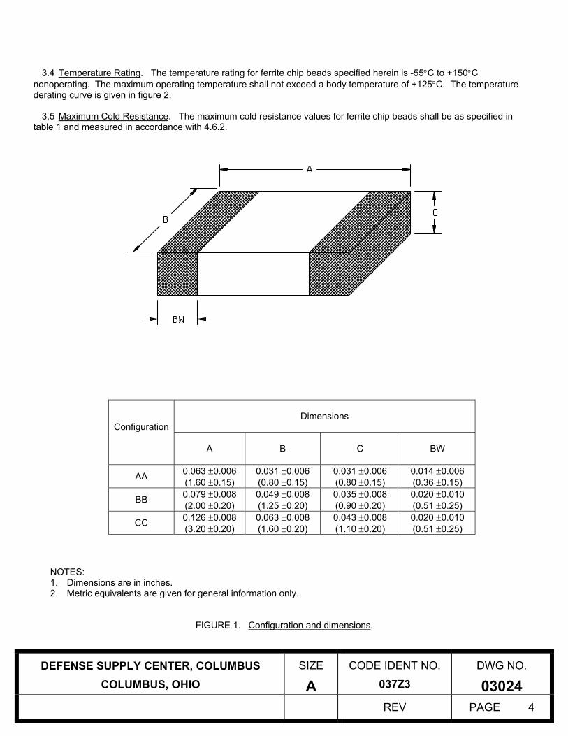
3.4 Temperature Rating. The temperature rating for ferrite chip beads specified herein is -55°C to +150°C nonoperating. The maximum operating temperature shall not exceed a body temperature of +125°C. The temperature derating curve is given in figure 2. 3.5 Maximum Cold Resistance. The maximum cold resistance values for ferrite chip beads shall be as specified in table 1 and measured in accordance with 4.6.2.
Dimensions
Configuration
A
B C BW
AA 0.063 ±0.006 (1.60 ±0.15)
0.031 ±0.006 (0.80 ±0.15)
0.031 ±0.006 (0.80 ±0.15)
0.014 ±0.006 (0.36 ±0.15)
BB 0.079 ±0.008 (2.00 ±0.20)
0.049 ±0.008 (1.25 ±0.20)
0.035 ±0.008 (0.90 ±0.20)
0.020 ±0.010 (0.51 ±0.25)
CC 0.126 ±0.008 (3.20 ±0.20)
0.063 ±0.008 (1.60 ±0.20)
0.043 ±0.008 (1.10 ±0.20)
0.020 ±0.010 (0.51 ±0.25)
NOTES: 1. Dimensions are in inches. 2. Metric equivalents are given for general information only.
FIGURE 1. Configuration and dimensions.
DEFENSE SUPPLY CENTER, COLUMBUS SIZE CODE IDENT NO. DWG NO.
COLUMBUS, OHIO A 037Z3 03024 REV PAGE 4
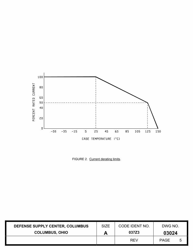
FIGURE 2. Current derating limits.
DEFENSE SUPPLY CENTER, COLUMBUS SIZE CODE IDENT NO. DWG NO.
COLUMBUS, OHIO A 037Z3 03024 REV PAGE 5
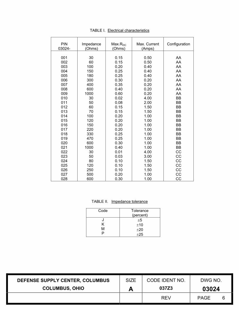
TABLE I. Electrical characteristics
PIN
03024-
Impedance
(Ohms)
Max.RDC (Ohms)
Max. Current
(Amps)
Configuration
001 002 003 004 005 006 007 008 009 010 011 012 013 014 015 016 017 018 019 020 021 022 023 024 025 026 027 028
30 60
100 150 180 300 400 600
1000 30 50 60 70
100 120 150 220 330 470 600
1000 30 50 80
120 250 500 600
0.15 0.15 0.20 0.25 0.25 0.30 0.35 0.40 0.60 0.02 0.08 0.15 0.15 0.20 0.20 0.20 0.20 0.25 0.25 0.30 0.40 0.01 0.03 0.10 0.10 0.10 0.20 0.30
0.50 0.50 0.40 0.40 0.40 0.20 0.20 0.20 0.20 4.00 2.00 1.50 1.50 1.00 1.00 1.00 1.00 1.00 1.00 1.00 1.00 4.00 3.00 1.50 1.50 1.50 1.00 1.00
AA AA AA AA AA AA AA AA AA BB BB BB BB BB BB BB BB BB BB BB BB CC CC CC CC CC CC CC
TABLE II. Impedance tolerance
Code Tolerance (percent)
J K M P
±5 ±10 ±20 ±25
DEFENSE SUPPLY CENTER, COLUMBUS SIZE CODE IDENT NO. DWG NO.
COLUMBUS, OHIO A 037Z3 03024 REV PAGE 6
3.6 Performance. 3.6.1 Thermal Shock (Group A). When ferrite chip beads are tested in accordance with 4.6.3, there shall be no evidence of electrical or mechanical damage. 3.6.2 Current Carrying Capacity. When ferrite chip beads are tested in accordance with 4.6.6, there shall be no evidence of mechanical damage and shall carry the current specified without electrical failure. 3.6.3 Termination Strength. When ferrite chip beads are tested in accordance with 4.6.7, the end terminations shall not break or loosen. The cold resistance values shall not change by more than ±10 percent. 3.6.4 Thermal Vacuum. When ferrite chip beads are tested in accordance with 4.6.16, they shall not open circuit during the application of derated DC current nor shall there be evidence of arcing or mechanical damage after the test. The impedance shall not change by more than ±10 percent when measured after thermal vacuum exposure. 3.6.5 Bending. When ferrite chip beads are tested in accordance with 4.6.14, they shall not break or loosen. The cold resistance values shall not change by more than ±10 percent. 3.6.6 Insulation Resistance. When ferrite chip beads are tested in accordance with 4.6.15, the insulation resistance shall be 1GΩ minimum. 3.6.7 Moisture Resistance (Group C). When ferrite chip beads are tested in accordance with 4.6.8, there shall be no evidence of cracking or peeling of the ferrite body or excessive corrosion of the terminations. The impedance shall not change by more than ±15 percent. 3.6.8 Shock (Group C). When ferrite chip beads are tested in accordance with 4.6.9, there shall be no evidence of mechanical damage and the impedance shall not change by more than ±10 percent. 3.6.9 Vibration (Group C). When ferrite chip beads are tested in accordance with 4.6.10, there shall be no evidence of mechanical damage and the impedance shall not change by more than ±10 percent. 3.6.10 Low Temperature Operation (Group C). When ferrite chip beads are tested in accordance with 4.6.12, they shall not open circuit and the cold resistance shall not change by more than ±10 percent. 3.6.11 Life (1000 Hours, Group C). When ferrite chip beads are tested in accordance with 4.6.13, they shall not open circuit and the impedance and cold resistance shall not change by more than ±20 percent. The cold resistance shall not exceed the maximum value specified. 3.6.12 Resistance to Soldering Heat. When ferrite chip beads are tested in accordance with 4.6.11, there shall be no mechanical damage and the cold resistance shall not change by more than ±10 percent. 3.6.13 Solderability. Ferrite chip beads shall meet the requirements specified in MIL-STD-202, Method 208. 3.6.14 Salt Spray (Group C). When ferrite chip beads are tested in accordance with 4.6.17, there shall be no evidence of excessive corrosion. Excessive corrosion is defined as that which interferes with electrical or mechanical performance. There shall be no warping or cracking of the ferrite body and the impedance shall not change by more than ±10 percent. 3.6.15 Outgassing. When ferrite chip beads are tested in accordance with 4.6.18, the materials shall meet the following requirements:
a) Total mass loss (TML) – Shall not exceed 1.0 percent. b) Collected volatile condensable material (CVCM) – Shall not exceed 0.1 percent.
DEFENSE SUPPLY CENTER, COLUMBUS SIZE CODE IDENT NO. DWG NO.
COLUMBUS, OHIO A 037Z3 03024 REV PAGE 7
Note: This requirement can be met by certification of materials, once product has been tested by an approved facility. 3.6.16 Thermal Shock 100 Cycle (Group C). When ferrite chip beads are tested in accordance with 4.6.20, there shall be no mechanical damage and the impedance shall not change by more than ±20 percent. 3.6.17 Resistance to Solvents. When ferrite chip beads are tested in accordance with 4.6.21, there shall be no mechanical damage.
3.7 Qualification. Qualification for this part is not required.
3.8 Recycled, recovered, or environmentally preferable materials. Recycled, recovered, or environmentally preferable materials should be used to the maximum extent possible provided that the material meets or exceeds the operational and maintenance requirements, and promotes economically advantageous life cycle costs.
3.9 Certificate of compliance. A certificate of compliance shall be required from manufacturers requesting to be a suggested source of supply. 3.10 Marking. Marking of the ferrite chip bead is not required; however, each unit package shall be marked in accordance with MIL-STD-1285 and include the PIN as specified herein (see 1.2), the manufacturer’s name or Commercial and Government Entity (CAGE) code, and date lot codes.
3.11 Workmanship. Ferrite chip beads shall be free of defects that will affect usable life or reliability.
4. VERIFICATION
4.1 Classification of Inspection. The inspection of ferrite chip beads procured to the requirements of this drawing shall be classified as Acceptance Inspection. 4.2 Test Equipment and Inspection Facilities. Manufacturers shall establish and maintain a calibration system in accordance with ANSI/NCSL Z540-1, ISO 10012-1 or equivalent. 4.3 Acceptance Inspection Reports. Manufacturers shall supply with each shipment of ferrite chip beads the following minimum data:
a) Non-standard test reports as required by the purchase order. b) Certification of Conformance signed by the Quality Assurance Manager. c) Group A and B data. d) Group C data, if required by the purchase order, shall be shipped at the completion of Group C inspection.
4.4 Inspection Conditions and Methods. Unless otherwise specified in this document, inspections shall be conducted at room ambient environments of +25°C ±5°C and the maximum relative humidity shall be 75 percent.
4.5 Acceptance Inspection. 4.5.1 Inspection of Ferrite Chip Beads. Inspection of ferrite chip beads for delivery shall consist of Group A, Group B and Group C data or Group A, Group B and the Certificate of Conformance in lieu of Group C.
4.5.2 Inspection Lot. An inspection lot shall consist of one impedance rating of one lot date code. 4.5.3 Group A Inspection. Group A inspection shall consist of the tests listed in table III and shall be conducted in the order indicated. 4.5.4 Group B Inspection. Group B inspection shall consist of the tests listed in table IV and shall be conducted in the order indicated. All ferrite chip beads submitted to Group B inspection shall have successfully met all electrical requirements of the Group A inspection (Visual rejects may be utilized for Group B inspection).
DEFENSE SUPPLY CENTER, COLUMBUS SIZE CODE IDENT NO. DWG NO.
COLUMBUS, OHIO A 037Z3 03024 REV PAGE 8
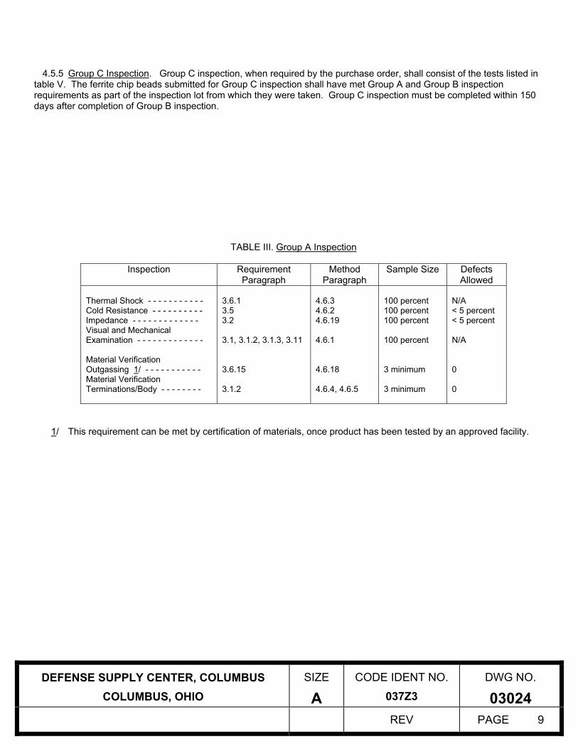
4.5.5 Group C Inspection. Group C inspection, when required by the purchase order, shall consist of the tests listed in table V. The ferrite chip beads submitted for Group C inspection shall have met Group A and Group B inspection requirements as part of the inspection lot from which they were taken. Group C inspection must be completed within 150 days after completion of Group B inspection.
TABLE III. Group A Inspection
Inspection Requirement Paragraph
Method Paragraph
Sample Size Defects Allowed
Thermal Shock - - - - - - - - - - - Cold Resistance - - - - - - - - - - Impedance - - - - - - - - - - - - - Visual and Mechanical Examination - - - - - - - - - - - - - Material Verification Outgassing 1/ - - - - - - - - - - - Material Verification Terminations/Body - - - - - - - -
3.6.1 3.5 3.2 3.1, 3.1.2, 3.1.3, 3.11 3.6.15 3.1.2
4.6.3 4.6.2 4.6.19 4.6.1 4.6.18 4.6.4, 4.6.5
100 percent 100 percent 100 percent 100 percent 3 minimum 3 minimum
N/A < 5 percent < 5 percent N/A 0 0
1/ This requirement can be met by certification of materials, once product has been tested by an approved facility.
DEFENSE SUPPLY CENTER, COLUMBUS SIZE CODE IDENT NO. DWG NO.
COLUMBUS, OHIO A 037Z3 03024 REV PAGE 9
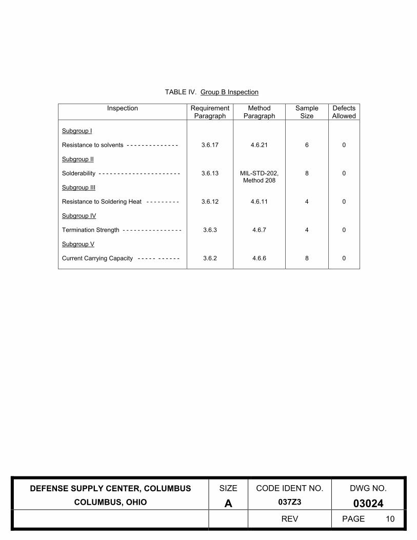
TABLE IV. Group B Inspection
Inspection Requirement Paragraph
Method Paragraph
Sample Size
Defects Allowed
Subgroup I Resistance to solvents - - - - - - - - - - - - - - Subgroup II Solderability - - - - - - - - - - - - - - - - - - - - - - Subgroup III Resistance to Soldering Heat - - - - - - - - - Subgroup IV Termination Strength - - - - - - - - - - - - - - - - Subgroup V Current Carrying Capacity - - - - - - - - - - -
3.6.17
3.6.13
3.6.12
3.6.3
3.6.2
4.6.21
MIL-STD-202, Method 208
4.6.11
4.6.7
4.6.6
6
8
4
4
8
0
0
0
0
0
DEFENSE SUPPLY CENTER, COLUMBUS SIZE CODE IDENT NO. DWG NO.
COLUMBUS, OHIO A 037Z3 03024 REV PAGE 10

TABLE V. Group C Inspection
Inspection Requirement Paragraph
Method Paragraph
Sample Size
Defects Allowed
Subgroup I Low Temperature Operation - - - - - - - - Life (1000 Hours) - - - - - - - - - - - - - - - Thermal Vacuum (Separate samples) - - Subgroup II Bending - - - - - - - - - - - - - - - - - - - - - - Subgroup III Vibration - - - - - - - - - - - - - - - - - - - - - - Shock - - - - - - - - - - - - - - - - - - - - - - - - Subgroup IV Salt Spray - - - - - - - - - - - - - - - - - - - - - - Thermal Shock (100 Cycle) - - - - - - - - - Subgroup V Moisture Resistance - - - - - - - - - - - - - Thermal Shock - - - - - - - - - - - - - - - - - Current Carrying Capacity (+25°C) - - - Subgroup VI Insulation Resistance - - - - - - - - - - - -
3.6.10 3.6.11 3.6.4
3.6.5
3.6.9 3.6.8
3.6.14 3.6.16
3.6.7 3.6.1 3.6.2
3.6.6
4.6.12 4.6.13 4.6.16
4.6.14
4.6.10 4.6.9
4.6.17 4.6.20
4.6.8 4.6.3 4.6.6
4.6.15
16 16 8
6
4 4
4 4
4 4 4
4
0 0 0
0
0 0
0 0
0 0 0
0
4.6 Methods of Inspection. 4.6.1 Visual and Mechanical Inspection. Ferrite chip beads shall be visually and mechanically examined per the
general visual acceptance criteria in accordance with EIA-595. 4.6.2 Resistance. The resistance of the ferrite chip bead shall be measured using a constant current DC source. The resistance of the ferrite chip bead shall be measured using one of the following methods: Method I - The measurement current shall be from 0.1 to 10 milliamperes and provide a measurement accuracy of ±1 percent. These measurements shall be made with a Keithley Model 580 Micro-ohmmeter or equivalent. Method II - The ferrite chip bead shall be electrically connected to a constant DC source supplying 10 percent of the rated current of the ferrite chip bead. The voltage drop of each ferrite chip bead shall be measured and the resistance calculated from the measured voltage drop.
4.6.3 Thermal Shock. Ferrite chip beads shall be tested in accordance with MIL-STD-202, method 107, test condition B. A total of five cycles shall be run without interruption.
DEFENSE SUPPLY CENTER, COLUMBUS SIZE CODE IDENT NO. DWG NO.
COLUMBUS, OHIO A 037Z3 03024 REV PAGE 11
4.6.4 Material Verification (Terminations). Ferrite chip bead samples shall be subjected to energy dispersive spectroscopy (EDS) or X-ray Fluorescence (XRF) to determine the following: a) The tin/lead terminations are no more than 97 percent tin. b) Existence of cadmium (none permitted). 4.6.5 Material Verification (Body). Ferrite chip bead samples shall be subjected to energy dispersive spectroscopy (EDS), also known as energy dispersive analysis of x-rays to determine the following: a) Existence of pure cadmium and cadmium alloys (none permitted). b) Existence of pure zinc (none permitted). 4.6.6 Current Carrying Capacity. Ferrite chip bead samples shall be apportioned and submitted to the following DC test currents at -55°C to -60°C, at +20°C to +35°C (room ambient temperature), and at +125°V to +130°C:
Test Temperature DC Test Current -55°C 110 percent of rated +25°C 100 percent of rated +125°C 80 percent of rated
The test current shall be maintained for 30 minutes after the temperature of each ferrite chip bead has stabilized, but shall not be applied for less than 1.5 hours. It may be assumed that the temperature has stabilized when three consecutive temperature readings taken at 10 minute intervals show no rise in temperature. The temperature of the ferrite chip bead body shall be measured by thermocouples (wire size 28 to 32 AWG). Group B current carrying capacity testing shall be conducted at room temperature conditions only. 4.6.7 Terminal Strength. Ferrite chip beads shall be tested in accordance with MIL-STD-202, method 211. The following exceptions shall apply: a) Test condition – Test condition A (0.5 kg for configuration AA; 1.0 kg for configuration BB; 1.5 kg for configuration CC) applying the force axially to each lead wire individually (solder .020 to .025 inch diameter wires with nail head to terminations prior to testing). Apply force for 30 seconds. b) Method of holding – The ferrite chip bead body shall be held by means other than rigid clamping. c) Measurements – DC resistance measurements shall be taken before and after exposure in accordance with 4.6.2.
4.6.8 Moisture Resistance (Group C). Ferrite chip beads shall be tested in accordance with MIL-STD-202, method 106. The following exceptions apply: a) Mounting – Normal mounting means by soldering onto a printed circuit board. b) No polarizing voltage applied. c) Steps 7a and 7b are not applicable. d) Measurements – Impedance measurements shall be taken before and after exposure in accordance with 4.6.19. 4.6.9 Shock (Group C). Ferrite chip beads shall be tested in accordance with MIL-STD-202, method 213. The following details and exceptions shall apply:
a) Mounting – Ferrite chip beads shall be securely fastened to the table of the shock machine to prevent motion
between the ferrite chip beads and the table (solder mounted on a printed circuit board). b) Test condition – Test condition F (1500 G’s). c) Number of shocks – Three shocks in each direction of three mutually perpendicular axes (18 shocks total). d) Measurements – Impedance measurements shall be taken before and after the shock exposure in accordance with 4.6.19. e) Rated current shall be applied to one half of the samples during testing.
DEFENSE SUPPLY CENTER, COLUMBUS SIZE CODE IDENT NO. DWG NO.
COLUMBUS, OHIO A 037Z3 03024 REV PAGE 12

4.6.10 Vibration (Group C). Ferrite chip beads shall be tested in accordance with MIL-STD-202, method 204. The following details and exceptions shall apply:
a) Mounting – Ferrite chip beads shall be securely fastened to the table of the vibration machine to prevent relative motion between the ferrite chip beads and the table. b) Test level – Sinusoidal vibration from 5 to 3000 hertz, 0.4-inch double amplitude or 30G’s peak, whichever is less. c) Sweep rate – Approximately ½ octave per minute. d) Test duration – 12 hours total (4 hours in each of three major axes). e) Measurements – Impedance measurements shall be taken before and after the vibration exposure in accordance with 4.6.19. f) Rated current shall be applied to one half of the samples during testing.
4.6.11 Resistance to Solder Heat. Ferrite chip beads shall be tested in accordance with MIL-STD-202, method 210, test condition B. The following details and exceptions shall apply: a) Impedance measurements shall be taken before and after the exposure in accordance with 4.6.19. 4.6.12 Low Temperature Operation (Group C). Ferrite chip beads shall be soldered on a suitable test board and placed in a low temperature chamber. The chamber temperature shall be lowered gradually to -55°C +0/-3°C within a period of 1 hour. After stabilizing at the low temperature for a period of 1 hour, rated DC current shall be applied to the ferrite chip beads for a period of 4 hours +1/-0 hours while at the low temperature. The chamber shall than be gradually raised to room temperature within a 4 hour period and maintained at room temperature for a period of 8 hours minimum. After this time, the DC current shall be removed from the ferrite chip beads and the ferrite chip beads removed from the chamber. The impedance of the ferrite chip beads shall be measured before and after the test in accordance with 4.6.19. 4.6.13 Life (1000 Hours, Group C). Ferrite chip beads shall be soldered on a suitable test board and placed in a chamber at +125°C +3/-0°C ambient. The ferrite chip beads shall be electrically connected to a DC source supplying 64 percent of the +25°C rated current. The ferrite chip beads shall remain in the chamber at the specified current for 1000 ±8 hours. The electrical circuit shall provide a suitable indicator, which shall be monitored daily during the length of the life test, to identify failure (opening) of any ferrite chip beads. The time of failure shall be recorded to the nearest ±12 hours and the open ferrite chip bead replaced with a short circuit for the remainder of the test. The impedance of the ferrite chip bead shall be measured before and after the test in accordance with 4.6.19. 4.6.14 Bending. Ferrite chip beads shall be solder mounted on a suitable printed circuit board and submitted to a 1mm bend as specified by IEC 60068-2-21, with the modification that the chip beads or inductors will be subjected to one bend of 1 mm. The bending shall be 5 seconds. The impedance of the ferrite chip bead shall be measured before and after the test in accordance with 4.6.19. 4.6.15 Insulation Resistance. The insulation of the ferrite chip beads shall be measured as specified by MIL-STD-202, method 302, test condition A. The following exceptions shall apply: a) A conductive band shall be placed on the surface of the body. b) The two terminations of the ferrite chip bead shall be shorted together. 4.6.16 Thermal Vacuum. Ferrite chip beads shall be mounted in suitable mount sockets. The ferrite chip beads shall then be placed in a vacuum chamber and the chamber evacuated to a pressure of 5 X 10⁻⁵ torr maximum. The temperature of the ferrite chip bead mount shall be controlled such that the temperature of the ferrite chip beads, measured with a thermocouple mounted on the ferrite chip bead body, is maintained at +125°C ±3°C for a period of 48 +4, -0 hours, while 90% of the +25°C rated current is flowing through each ferrite bead. The impedance of the ferrite chip beads shall be measured before and after the test in accordance with 4.6.19.
DEFENSE SUPPLY CENTER, COLUMBUS SIZE CODE IDENT NO. DWG NO.
COLUMBUS, OHIO A 037Z3 03024 REV PAGE 13
4.6.17 Salt Spray (Group C). Ferrite chip beads shall be tested in accordance with MIL-STD-202, method 101. The following details shall apply: a) Five percent salt solution. b) Test condition B. c) Following the drying period, the ferrite chip beads shall be subjected to 100 percent of rated current for 1 hour. d) Following the test the ferrite chip beads shall be examined for compliance with 3.6.14. 4.6.18 Outgassing. The ferrite chip beads shall be tested as specified in ASTM E595. 4.6.19 Impedance. The impedance of the ferrite chip beads shall be measured at 100 MHz. 4.6.20 Thermal Shock (100 Cycle, Group C). Ferrite chip beads shall be tested in accordance with MIL-STD-202, method 107, test condition B. Prior to testing, the ferrite chip beads shall be solder mounted onto a printed circuit board. A total of one hundred cycles shall be run without interpretation. The impedance of the ferrite chip beads shall be measured before and after the test in accordance with 4.6.19.
4.6.21 Resistance to Solvents. Ferrite chip beads shall be tested in accordance with MIL-STD-202, method 215.
5. PACKAGING 5.1 Packaging. For acquisition purposes, the packaging requirements shall be as specified in the contract or order (see 6.2). When actual packaging of materiel is to be performed by DoD personnel, these personnel need to contact the responsible packaging activity to ascertain requisite packaging requirements. Packaging requirements are maintained by the Inventory Control Point's packaging activity within the Military Department or Defense Agency, or within the Military Department's System Command. Packaging data retrieval is available from the managing Military Department's or Defense Agency's automated packaging files, CD-ROM products, or by contacting the responsible packaging activity. 6. NOTES (This section contains information of a general or explanatory nature, which may be helpful, but is not mandatory.)
6.1 Intended use. Ferrite chip beads are intended for use in high reliability surface mount applications.
6.2 Ordering data. The contract or purchase order should specify the following: a. Complete PIN (see 1.2). b. Requirements for delivery of one copy of the conformance inspection data or certificate of compliance that parts
have passed conformance inspection with each shipment of parts by the manufacturer. c. Requirements for packaging and packing. 6.3 Users of record. Coordination of this document for future revisions is coordinated only with the Approved sources of supply and the users of record of this document. Requests to be added as a recorded user of this drawing should be in writing to: Defense Supply Center, Columbus, ATTN: DSCC/VAT, Post Office Box 3990, Columbus, OH 43216-5000 or by telephone (614) 692-0557 or DSN 850-0557.
DEFENSE SUPPLY CENTER, COLUMBUS SIZE CODE IDENT NO. DWG NO.
COLUMBUS, OHIO A 037Z3 03024 REV PAGE 14

DEFENSE SUPPLY CENTER, COLUMBUS COLUMBUS, OHIO
SIZE
A
CODE IDENT NO. 037Z3
DWG NO.
03024 REV PAGE 15
6.4 Approved sources of supply. Approved sources of supply are listed herein. Additional sources will be added as they become available. For assistance in the use of this drawing, contact Defense Supply Center, Columbus, ATTN: DSCC-VAT, Post Office Box 3990, Columbus, OH 43216-5000 or by telephone (614) 692-0557 or DSN 850-0557.
DSCC drawing
PIN 1/
Vendor similar designation or type number 2/
Vendor CAGE
Vendor name and address
03024-001* HRB0603*300*.500** 03024-002* HRB0603*600*.500** 03024-003* HRB0603*101*.400** 03024-004* HRB0603*151*.400** 03024-005* HRB0603*181*.400** 03024-006* HRB0603*301*.200** 03024-007* HRB0603*401*.200** 03024-008* HRB0603*601*.200** 03024-009* HRB0603*102*.200** 03024-010* HRB0805*300*4.00** 03024-011* HRB0805*500*2.00** 03024-012* HRB0805*600*1.50** 03024-013* HRB0805*700*1.50** 03024-014* HRB0805*101*1.00** 03024-015* HRB0805*121*1.00** 03024-016* HRB0805*151*1.00** 03024-017* HRB0805*221*1.00** 03024-018* HRB0805*331*1.00** 03024-019* HRB0805*471*1.00** 03024-020* HRB0805*601*1.00** 03024-021* HRB0805*102*1.00** 03024-022* HRB1206*300*4.00** 03024-023* HRB1206*500*3.00** 03024-024* HRB1206*800*1.50** 03024-025* HRB1206*121*1.50** 03024-026* HRB1206*251*1.50** 03024-027* HRB1206*501*1.00** 03024-028* HRB1206*601*1.00**
1GLF1
AEM Inc. 11525 Sorrento Valley Road San Diego, CA 92121
1/ When “*” is used for coded values, it’s the contractors responsibility to select those options allowed by the DSCC Drawing. 2/ CAUTION: Do not use this number for item acquisition. Items acquired to this number may not satisfy the performance requirements of this drawing.