l&u dok. sente - oljedirektoratet · before starting this second completion/ test programme,...
TRANSCRIPT
A/S NORSKE SHELL E & P
Denne rapporttilhorer
L&U DOK. SENTE
KODE Wrll 31 /a,- i «sReturneres etter bruk
TANANGER
COMPLETION & PRODUCTION TEST
PROGRAMME
NUMBER 2
WELL
RIG "BORG
Jl/2-15
DOLPHIN"
-A . >̂ :;°~. "z.-̂ : v- .'•••* • •• , ̂ : & .' '* * >-• '' •
24 October 1984
OPERAlfoNS
SEN.OPERATIONS ENG.
CHIEF PETR. ENG.
TECHNICAL MANAGER

A/S NORSKE SHELL E & P
TANANGER
COMPLETION & PRODUCTION TEST
I PROGRAMME
NUMBER 2
WELL 31/2-15
RIG "BORGNY DOLPHIN"
24 October 1984
OPERATIONS
CHIEF PETR. ENG.
TECHNICAL MANAGER
SEN.OPERATIONS ENG.

CONTENTS
PRODUCTION TESTi DESCRIPTION
1.1 Test Objec1.2 Programme1.3 Sequence c1.4 General
WELL DATA
2.1 Reservoir2.2 Completior2.3 Perforatic2.4 Depth Reft2.5 Gun Type2.6 Gauge Typ<
DETAILED OPERA'
3.1 Preparatii3.2 Running T3.3 Drawdown/3.4 Flow Test3.5 Retrievin
tivesOutlinesif Operations
DataFluid
m Interval•rence
t
riONjn/ Setting Packerjst String with tubing conveyed gunPerforatingProgramme
3 Test String
APPENDICES
1.2.3.4.5.6.7.8.9.10.11.12.13.
PressurePreparation of Tubing
Testing Surface Lines and EquipmentSafety Procedure for Handling MercurySafety Procedure for Handling ExplosivesFlowing the WellHandling lof Completion BrineContingency MeasuresWell Staius 31/2-15Measurements RequiredProcedure for Recombination SamplesSand DetectionSpecial IpST Tools in Test StringTesting Organisation
PAGE NO.
3334
555555
68101113
14151617181921232425262728
FIGURES
1.2.3.4.5.
EZ-tree space outPerforating/ Test StringGun/ Seajl Assembly space outSurfaceFormation Log
Equipment Layout
test 31/2-15 2

1.1.1
PRODUCTION TEST DESCRIPTION
1.2
Test Objective (Test no. 2)i
The hydrocarbon bearing reservoir section will be tested in theinterval 1564 - 1567 in BDF (3 m) in the consolidated, micaceoussand to determine the1 nature of the fluids in the zone ofuncertainty (1561 - 1J568 m) with respect to the GOC.
Programme Outline
The production packer. from test no.l will be pushed to bottom andthe perforated interval 1572 - 1580 m will be secured with cementand bridge plug. Folpacker will be set.tubing conveyed guns
lowing an inflow test on the plug a productionA 3i" completion string will be run withon bottom, the guns spaced out on depth, a
flowhead installed aijid the well perforated under drawdown.Following a clean up j period, gauges may be run and the well flowtested and shut in for pressure build up.
1.3 Sequence of Operations
1.3.1
1.3.2
1.3.3
1.3.4
1.3.5
1.3.6
1.3.7
1.3.8
1.3.9
1.3.10
1.3.11
1.3.12
1.3.13
1.3.14
1.3.15
1.3.16
1.3.17
1.3.18
Mill packer at
RIH with cement- 1580 m BDF).
RIH with bit ar
RIH with GR/CCL
RIH with bit ar(Schlumberger c
Set model N-l t
Pressure test c
RIH with RTTS f370 psi drawdov
Circulate well
Set Baker "F-l
Pressure test
Run 3J" test s
Test string to
1528 m BDF and push packer to bottom.
stinger and squeeze off the perforations (1572
d dress down cement to 1567 m BDF.
for depth correlation.
d scraper and dress cement down to 1572 mepth).
ridge plug at 1571 m BDF.
:asing to 4000 psi.
>acker and inflow test the bridge plug with +/-*n.
clean and displace to clean brine.1 production packer.
the BOP stack.
bring with tubing conveyed guns on bottom.
4000 psi and land string.
Displace tubing with diesel to give approx. 300 psi drawdown.
Perforate unde'rbalanced the interval 1564 - 1567 m BDF byrunning the detonating bar on wireline.
Flow well to clean up.
Run pressure c
Carry out main
auges (if required).
flow test (if required).
test 31/2-15 2

1.3.19 Close in well for build-up and retrieve the gauges (ifrequired).
1.3.19 Kill well and retrieve test string.
1.4 General
The well has been drilled to a Total Depth of 1677 m BDF. The9-5/8" casing has been set with shoe at 1663 m and float collar at1634 m. The well was displaced to 1.20 SG brine and a productionpacker set at 1528 m. The well was perforated over the interval1572 - 1580 m and production tested. The perforating assembly(28.5 m long) was dropped giving a hold up depth of +/- 1605 m BDF.Before starting this second completion/ test programme, the wellwill be killed and the test string pulled racking both the 4i"riser tubing and the 3i" test tubing.
test 31/2-15 2
2. WELL DATA
2.1 Reservoir Data
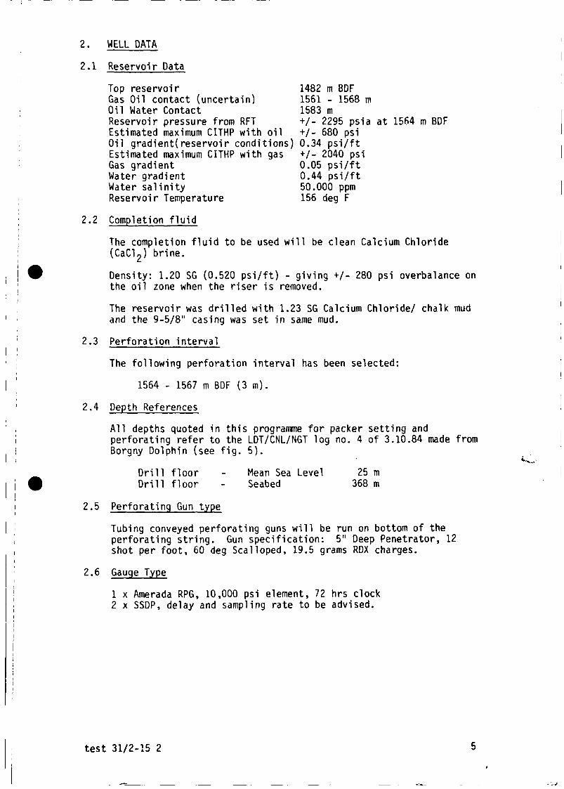
Top reservoir 1482 m BDFGas Oil contact (uncertain) 1561 - 1568 mOil Water Contact 1583 mReservoir pressure from RFT +/- 2295 psi a at 1564 m BDFEstimated maximum CITHP with oil +/- 680 psiOil gradient(reservoir conditions) 0.34 psi/ftEstimated maximum CITHP with gas +/- 2040 psiGas gradient 0.05 psi/ftWater gradient 0.44 psi/ftWater salinity 50.000 ppmReservoir Temperature 156 deg F
2.2 Completion fluid
The completion fluid to be used will be clean Calcium Chloride(CaCl2) brine.
Density: 1.20 SG (0.520 psi/ft) - giving +/- 280 psi overbalance onthe oil zone when the riser is removed.
The reservoir was drilled with 1.23 SG Calcium Chloride/ chalk mudand the 9-5/8" casing was set in same mud.
2.3 Perforation interval
The following perforation interval has been selected:
1564 - 1567 m BDF (3 m).
2.4 Depth References
All depths quoted in this programme for packer setting andperforating refer to the LDT/CNL/NGT log no. 4 of 3.10.84 made fromBorgny Dolphin (see fig. 5).
«-v-*'
Drill floor - Mean Sea Level 25 mDrill floor - Seabed 368 m
2.5 Perforating Gun type
Tubing conveyed perforating guns will be run on bottom of theperforating string. Gun specification: 5" Deep Penetrator, 12shot per foot, 60 deg Scalloped, 19.5 grams RDX charges.
2.6 Gauge Type
1 x Amerada RPG, 10,000 psi element, 72 hrs clock2 x SSDP, delay and sampling rate to be advised.
test 31/2-15 2

3. DETAILED OPERATION
General
A. Cleanliness
The success of the test is dependent on the cleanliness of all thefluids pumped in the hole, and the cleanliness of all the equipmentrun in the hole. Great care should be taken to achieve anacceptable level of cleanliness. Two specific items of concern areas follows:
i) Ensure ALL relevant circulating lines are cleaned of mud, usingseawater. This includes choke and kill lines, and all lineswhich may be used in the brine circulation system. This shouldbe carried out whilst circulating the well clean and beforerunning the completion testing string.
ii) DO NOT USE EXCESSIVE O.P. DOPE. - Dope pins only using a smallpaint brush and wipe off excess dope squeezed out of theconnection.
B. Safety
i) All operations involving tripping with small bore pipe (3J",2-7/8", etc) should be treated with a maximum of care. Hole fillupvolumes are to be calculated and checked and the tallies recordedin a neat format.
ii) If evidence of swabbing is noted during tripping, install aninside BOP on the DP immediately to maintain control over the DPshould it come live. Whilst the annulus remains stable, run inhole as deep as possible before shutting in the well andcirculating out the influx. If the annulus starts to flow,install kelly, close in well, and circulate/ control well at thatdepth.
3.1 Preparation
Prior to carrying out step 3.1.1 below test no.l will have beenconcluded and the production string pulled out of the hole (seeitem 1.4).
3.1.1 RIH with a model "CJ" packer milling tool on 5" DP and millthe packer at 1528 m. Push the packer to bottom. (Hold updepth +/- 1605 m). POH with milling tool.
NOTE : The 1.20 SG brine in the hole will be used asworkover fluid, with frequent use of viscous pill toaid cleaning of the well.
3.1.2 RIH with 150 m of 2-3/8" tubing stinger on 5" DP to bottom.Circulate at least one drill pipe volume.
3.1.3 Set a balanced cement plug (abandonment plug no.l) from 1600 -1500 m (100 m) using the following slurry:
15.8 ppg Class G cement0.15 gps CFR-2L4.96 gps Freswhater1.16 cuft/sx yield(Thickening time +/- 2 hrs)
test 31/2-15 2

3.1.4 POH to 30 m above estimated TOC and reverse circulate clean.Close the BOP1s around the pipe and apply 2000 psi to attemptto squeeze away approx. 6 bbls of slurry by hesitation squeezeleaving the top of cement at +/- 1525 m. Maintain pressure onthe cement until surface samples are hard and POH.
3.1.5 RIH with 8i" bit and locate top of cement. Dress off thecement plug down to 1567 m BDF (to within 5 m of old perfs.).POH.
3.1.6 Rig up Schlumberger and run 3-3/8" GR/CCL and record exactdepth of top of the cement plug. Rig down Schlumberger.
3.1.7 RIH with bit and scraper and drill cement down to 1572 mSchlumberger depth. Scrape the interval 1572 - 1500 m.Circulate clean and POH racking the 5" DP.
3.1.8 Rig up Schlumberger and run gauge ring/ junk basket (OD =8.300") down to top cement. Set a Baker model N-l bridge plugat 1571 m. It is essential that the packer is not set higherthan 1570 m leaving 3 m sump below next perforating interval.Rig down Schlumberger.
3.1.9 RIH with 8i" RTTS packer and one joint of drill pipe below thepacker to +/- 1570 m. Break circulation.
3.1.10 Close the pipe rams around the pipe and pressure test thecasing and bridge plug to 4000 psi for 30 min.
3.1.11 Circulate diesel to +/- 1500 m BDF, set packer and bleed offsurface pressure to inflow test the bridge plug for 1 hr.(Drawdown will be +/- 370 psi). Unset packer and reversecirculate bottoms up. Check for influx (salinity/ gas/ oil).If OK, proceed with next step. If leak is observed contactbase, whereon a further programme will be initiated.
3.1.12 After the successful inflow test, circulate well clean anddisplace the brine in the hole with new brine of 1.20 SG. POHwith packer racking the DP.
NOTE : a) Use viscous pills and seawater as spacer.
b) Keep the old brine as back up on surface.
c) No filtering of the brine is required unless returnsare extreemly dirty.
3.1.13 Rig up Schlumberger and run gauge ring/ junk baset (OD =8.300") down to the bridge plug.
3.1.14 RIH on Schlumberger line and set at +/- 1532 m BDF, the BakerModel "F-l", size 192-60 retainer production packer with 6"bore and max OD = 8.218". POH and rig down Schlumberger.
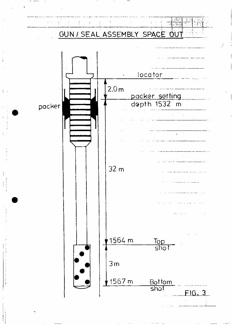
NOTE : a) Setting depth will be top of packer bore (See fig.3).
b) Setting depth is selected such that the perforatingguns will be on depth when the G-22 seal assembly isspaced out, i.e. the locator 2.0 m above top locatorbore.
test 31/2-15 2

c) The sub assembly will be re-measured on the site andthe packer setting depth adjusted accordingly ifrequired.
3.1.15 Pick up the Flopetrol EZ-tree and function test the same. Acomplete dummy run with the 4i"i tubing riser is not requiredsince already carried out prior to test no.l as described inthe note below.
NOTE : a) Make up fluted hanger, slick joint and SSTT. Atthis stage connect hydraulic hoses and testunlatching/ latching feature. Blank off injectionand control line ports and run 4i", 19.2 lbs/ft,C-75, PH-6 tubing riser including lubricator valve(+/- 30 m BDF) with blanked off control line ports.Run in and land fluted hanger on wearbushing. Spaceout so that top of tubing riser is +/- 5 metersabove rig floor. Close/ open 5" pipe rams. Pull outand stand 4i" riser back in derrick, including SSTT.Check for ram-impressions on slick joint.
b) Make up the flowhead on one single of 4i" PH-6tubing joint and lay down same on piperack.
3.1.16 Pressure test the BOP stack according to item 3.1.4 in thedrilling programme.
3.2 Running Test String with Tubing Conveyed Gun
3.2.1 Make up the guns and associated subassemblies as per fig. 2including the first 3i" VAM single.
NOTE : a) Refer to Appendix 4 for safety precautions whilsthandling the tubing conveyed guns.
b) The Sliding Side Door (SSD) will be run in closedposition.
c) The PCT valve will be run in locked open position.See Appendix 12.
d) The ported-compensating disc assembly and perforatedpipe will allow the string to fill with brine whilerunning the string in the hole.
e) The length from the top shot on the gun to the G-22locator on the Baker seal assembly, should be spacedout such that as when the string is landed with theG-22 locator 2.0 m above the top of the packer bore,the guns are in correct perforating position, (seefig. 3).
3.2.2 Rig up test sub with Flopetrol 10,000 psi wireline BOP on topon the tubing string. RIH with wireline and set the RN testtool in the 2-7/8" RN - nipple. With wireline latched ontothe plug, pressure test the tubing to 4,000 psi surfacepressure for 30 minutes. After successful pressure test,retrieve the test tool and rig down the wireline equipment andtest sub.
test 31/2-15 2
NOTE : a) While pressure testing, increase pressure in stages of1,000 psi holding each step for 1 minutes whileobserving pressure.Test pressure of 4,000 psi shouldbe held for 30 minutes. If drop occurs let itstablize for 10 minutes. Then increase to 4,000 psiagain which should then be held for full 30 minutes.Keep annul us open, and monitor volumes pumped andreturned.
b) Make sure cable is centralized in BOP while closingthe BOP to avoid cutting the wire.
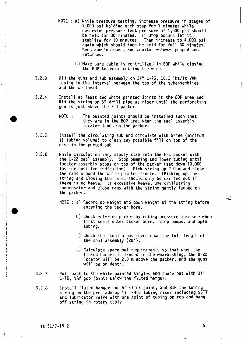
3.2.3 RIH the guns and sub assembly on 3i" C-75, 10.2 lbs/ft VAMtubing in the interval between the top of the subassembliesand the wellhead.
3.2.4 Install at least two white painted joints in the BOP area andRIH the string on 5" drill pipe as riser until the perforatinggun is just above the F-l packer.
NOTE : The painted joints should be installed such thatthey are in the BOP area when the seal assemblylocator lands on the packer.
3.2.5 Install the circulating sub and circulate with brine (minimumH tubing volume) to clean any possible fill on top of thedisc in the ported sub.
3.2.6 While circulating very slowly stab into the F-l packer withthe G-22 seal assembly. Stop pumping and lower tubing untillocator assembly stops on top of the packer (set down 10,000Ibs for positive indication). Pick string up 2.0 m and closethe rams around the white painted single. (Picking up thestring and closing the rams, should only be carried out ifthere is no heave. If excessive heave, use drillstringcompensator and close rams with the string gently landed onthe packer.
NOTE : a) Record up weight and down weight of the string beforeentering the packer bore.
b) Check entering packer by noting pressure increase whenfirst seals enter packer bore. Stop pumps, and opentubing.
c) Check that tubing has moved down the full length ofthe seal assembly (201).
d) Calculate space out requirements so that when thefluted hanger is landed in the wearbushing, the G-22locator will be 2.0 m above the packer, and the gunswill be on depth.
3.2.7 Pull back to the white painted singles and space out with 3i"C-75, VAM pup joints below the fluted hanger.
3.2.8 Install fluted hanger and 5" slick joint, and RIH the tubingstring on the pre made-up 4i'' PH-6 tubing riser including SSTTand lubricator valve with one joint of tubing on top and hangoff string in rotary table.
«it 31/2-15 2

NOTE : Space out so that when flowhead is installed it willbe +/- 5 m above rig floor.
3.2.9 Pressure test the test string to 4,000 psi as in step 3.2.2above. Pressure test the lubricator valve from above to 4,000psi.
NOTE : Ensure that the seal assembly is not stabbed into thepacker bore.
3.2.10 RIH the string and stab the seal assembly into packer bore.Hang off the string in the rotary table.
3.2.11 Pick up flowhead already made up on the 4i" PH-6 joint,install 50' x 2i" wire slings between bails and flowheadelevator.
3.2.12 Install chicksan lines to flow and kill sides on flowhead.Connect assembly to upfacing tubing connection in rotarytable. Land fluted hanger into wearbushing. Connect the killline to the Dowel 1 unit and flow line to the sandfilterpositioned on the rig floor.
3.2.13 Pressure test the flowhead against the lubricator valve to4,000 psi for 30 min.
3.2.14 Pressure test all surface lines to 4,000 psi for 30 minutes.
3.2.15 Close middle 5" pipe ram and pressure test annulus to 500 psi/15 minutes down kill line to check packer/ seal assembly.Keep rams closed.
NOTE : The PCT valve will actuate at 2500 psi annuluspressure.
3.3 Drawdown/ Perforating
3.3.1 Pressure up annulus to maximum 2500 psi to actuate the PCTvalve and bleed off pressure to zero, leaving the PCT closed.
NOTE : The PCT-valve is pre-set in open position beforerunning in hole by a pressurized chamber keeping thevalve in open position. To actuate the valve,annulus applied pressure will rupture a disc therebyrelieving the pressure in the tool which allows amandrel to move and the ball valve will close.
3.3.2 Open up the Multiple Opening Reversing Valve (MORV) bypressuring up the string against the PCT valve (approx. 2000psi required).
NOTE : The MORV has a 9 cycle combination of index sleeves,and the valve has to be pressure cycled nine timesbefore it opens. (This includes cycles made forpressure testing).
3.3.3 Displace the tubing to diesel taking returns up kill line, togive 300 psi drawdown on the formation, then close the MORV.
NOTE : a) Displacement rate can be 3 BPM maximum. To closethe MORV increase pump rate to 4.5 BPM and note
test 31/2-15 2 10

pressure increase indicating that the valve hasclosed.
b) Reservoir pressure at 1564 m from RFT is 2295 psia,and diesel density assumed at 0.85 SG. Diesel/water interface should be approximately 1350 m BDF.
3.3.4 Open up the PCT valve and keep it open for the duration of thetest (approx. 1200 psi is required to keep the valve open).
3.3.5 Rig up Flopetrol lubricator on top of the flowhead with theswab valve closed, install the detonating bar connected to theslick wireline, in the lubricator. Pressure test lubricatorto 4,000 psi/ 15 min.
NOTE : The wireline assembly will consist of from bottom:
detonating bar (flat bottom) (1.25" OD)running tool (1.50" OD)wireline jar (1.50" OD)13 feet stem (1.50" OD)
The length of this assembly is designed such that thetop of the assembly is below the ported sub whenfiring the gun.
3.3.6 Open the swab valve and RIH with detonating bar on wirelineand fire the gun.
NOTE : a) Firing the gun will take place in daylight.
b) While firing the gun, make sure that the flow lineis open to the gauge tank bypassing the separator.
3.4 Flow Test Programme
General
This outline flow test programme is a guide only. Specific itemse.g. rates and durations, lengths of build ups etc. may be variedin the light of onsite information gained during the test. Thefollowing point should however, be noted:
i) Flow through the 6"/5000 psi flowline.
ii) Inject glycol via the chemical injection line to the EZ treeand at separator and choke manifold.
iii) Once it has been ascertained that there is no sand productionbypass the sand filter at high flow rates. Be prepared toswitch flow through the sand filter if sand production occurs.
iv) Install errosion probes in flow line between flowhead and sandfilter.
v) Maintain a pressure of at least +/- 1500 psi greater than FTHPon the ball valve of the EZ tree.
vi) In all wireline work where the swab valve or lubricator valveis closed, the lubricator is to be filled with a 50/50water/glycol for the oil test. Prior to opening, the
test 31/2-15 2 11

lubricator is to be re-pressurized to equalize across thevalve used.
vii) When using the downhole valve, always equalize pressure overthe valve before opening.
3.4.1 After firing the gun, immediately back surge the well for 2minutes before beaning back and let the well flow at a maximumrate of 300 BPD into the gauge tank for approximately 2 hrs toclean up.
NOTE : a) Due to the uncertainty of the nature of thehydrocarbons in the reservoir, gas or oil or gas/oilcould be produced. It is therefore important tokeep the flow rate as low as practical possiblewhile producing back the diesel cussion to avoidpossible gas break through if oil is the predominantreservoir fluid.
b) If the well dies after flowing for a while, the wellwill be brought live again by; closing the PCTvalve, opening the multiple opening reversing valve,reversing out the tubing contents, displacing thetubing to diesel, closing the reversing valve,opening up the PCT valve and re-opening the well.
3.4.2 After 2 hrs clean up (or if the well has died) close in thewell at the sandtrap and pull the wireline assembly back intothe lubricator, close lubricator valve and remove WL assembly.
3.4.3 Open up the well and continue to produce clean keeping flowrate below 300 BPD until reservoir fluids are produced tosurface. Take sample of reservoir fluid and inform basewhereon a further clean up programme (rates, duration etc.)will be advised. When well is clean, consult with base beforeclosing in the well.
NOTE : a) If oil is produced throughout the clean up phase,the test will proceed with item 3.4.4 below.
b) If gas is produced (not associated gas) during cleanup, the well will be shut in (to be confirmed) andthe test terminated.
c) Take surface samples of produced fluids and one PVTrecombination sample at the separator during theclean up period.
3.4.4 Make drift run to the top of the gun. Install pressure gaugesas described in step 2.6, in Flopetrol lubricator and pressuretest same. When CITHP has stabilised run gauges to the Baker"F"-nipple. Make gradient stops in the lubricator and at 150m, 100 m and 50 m above the 'F1-nipple while RIH.
3.4.5 Open up the well and flow for 24 hrs.
NOTE : a) Flow rates to be advised based on clean upperformance.
b) If no gas break through has occured within the 24hrs period, the flow period may be extended.
test 31/2-15 2 12
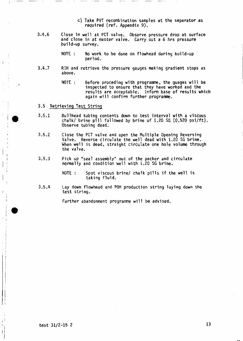
c) Take PVT recombination samples at the separator asrequired (ref. Appendix 9).
3.4.6 Close in well at PCT valve. Observe pressure drop at surfaceand close in at master valve. Carry out a 6 hrs pressurebuild-up survey.
NOTE : No work to be done on flowhead during build-upperiod.
3.4.7 RIH and retrieve the pressure gauges making gradient stops asabove.
NOTE : Before preceding with programme, the guages will beinspected to ensure that they have worked and theresults are acceptable. Inform base of results whichagain will confirm further programme.
3.5 Retrieving Test String
3.5.1 Bullhead tubing contents down to test interval with a viscouschalk/ brine pill followed by brine of 1.20 SG (0.520 psi/ft).Observe tubing dead.
3.5.2 Close the PCT valve and open the Multiple Opening ReversingValve. Reverse circulate the well dead with 1.20 SG brine.When well is dead, straight circulate one hole volume throughthe valve.
3.5.3 Pick up "seal assembly" out of the packer and circulatenormally and condition well with 1.20 SG brine.
NOTE : Spot viscous brine/ chalk pills if the well istaking fluid.
3.5.4 Lay down flowhead and POH production string laying down thetest string.
Further abandonment programme will be advised.
test 31/2-15 2 13

APPENDIX l
PREPARATION OF TUBING
1. Offload and rack tubing, separating each layer with at least threeevenly spaced wooden strips.
2. Number and measure each joint. WSPE and Production Test Supervisorboth to check tubing tallies.
3. Remove pin and box protectors, inspect threads for damage, clean withsolvent, and if possible, with steam.
4. Brush each joint to remove scale and loose solids: if any joint hasexcessive scale it should be rejected.
5. Drift each joint with appropriate 42" long tubing drift. All driftsshould be fitted with a fishing neck.
6. Reclean pins and boxes and replace protectors. (N.B. Protectorsshould also be clean and only lightly doped).
7. Check that there are a reasonable number of pup joints for spacing.
8. Inform shore of any further tubing requirements.
9. Return any unsatisfactory joints.
PREPARATION OF TUBING SUB-ASSEMBLIES EQUIPMENT
1. Physically check all tubing sub-assemblies and inspect and cleanthreads with solvent.
2. Ensure that spares of each item are available on the rig.
3. Function test all equipment (sliding sleeves, nipples, etc.)
4. Run wireline drift through each sub-assembly paying particularattention to polished sections as these can easily be squeezed inmake up. N.B. Separate drift runs should be made down to and throughNo-Go nipples.
5. Carry out API pressure test on each sub-assembly to 4,000 psi (tobe witnessed by WSPE, TP and Production Test Supervisor).
NOTE: Items 2 through 6 only when not carried out on-shore andwitnessed by PTS.
6. Accurately measure each tubing sub-assembly and note the position ofall accessories.
7. Replace protectors on each end of the tubing sub-assemblies.
8. Examine sub-assemblies for tong damage. If excessive, a newsub-assembly should be made up.
9. TP and WSPE to carry out final dimensions check.
test 31/2-15 2 14

APPENDIX 2
PRESSURE TESTING SURFACE LINES AND EQUIPMENT
Before the well is flow tested (preferably prior to installation of thestring) the following equipment will have been function/pressure tested onthe deck as follows:
FlowheadAll inlet/outlet connections are to be blanked off with testsubs.Pressure test body with all valves open. All valves pressure tested frombelow.
Production Test EquipmentThe following tests should be carried out before the installation of thetest string in order to save rig time. Connect the cement discharge lineto the 2" test line and pressure test as follows:
Lines to burners : 1000 psi/15 minLines to oil and gas manifold : 1000 psi/15 minSeparator : 1350 psi/15 minRelief valve(s) on separator : +/- 1450 psi (only if not
recently done onshore andwitnessed by Shellrepresentative).
Flush the valves clean by pumping +/- 1 bbl of water and close the valveby bleeding the pressure to zero.
Lines to upstream inlet of separator andBy-pass valve : 1,350 psi/15 minCheck "P" pilot trips at +/- 1350 psiLines downstream of steam heat exchanger: 4,000 psi/15 minLines upstream of steam heat exchanger : 4,000 psi/15 min
With 4,000 psi through the choke manifold close all valves on same andbleed off the pressure between the upstream and downstream valves.Observe for leakages.
Calibrate the oil and water meters while hooked-up to the pump line.
TESTS TO BE CARRIED OUT AFTER THE INSTALLATION OF THE PRODUCTION EQUIPMENT
With the flowhead mastergate closed and the kill line/flowline chicksanloops installed pressure test against the closed choke manifold to 4,000psi/ 15 mins.
Checks should be carried out to ensure the following auxiliaries areoperational:1. Steam supply to the steam heat exchanger, the condensate feed back
line to the rig system, and the steam degasser system.2. Rig air supply to the burners.3. Water sprays to burnerheads. Cooling water to the rig's hull/cranes
etc readily available and at sufficient pressure.
NOTE: After pressure testing the burner boom oil and gas lines allvalves downstream of the T-manifold must be kept open to allowfor quick change-over of burners.
test 31/2-15 2 15

APPENDIX 3
SAFETY PROCEDURE FOR HANDLING MERCURY
Mercury is used offshore for re-combination surface sampling and transfer ofbottom hole samples in order not to modify the composition of the sample.
Mercury Handling Equipment to be used
1. The test operators who are to perform the operations utilizing mercurymust report with all necessary protective equipment. Protectiveequipment is defined as follows:
a) Coveralls without pockets.b) Snugly fitting splash goggles.c) Suitable breathing mask.
Any other person(s) in the area who may come in contact withmercury or mercury vapor will be required to utilize similarprotective equipment.
d) Mercury exposure control form.e) Drager tube colormetric kit for checking the presence of mercury
vapor.f) SRM Mercury spill control center.
2. The personal protective equipment shall be left separate from otheritems of equipment or clothing and on completion of work will be placedin sealed plastic bags which are to be labelled "Mercury Contaminated"and returned to Flopetrol for handling in accordance with statutoryrequirements and safety standards.
3. Used breathing masks will be handled in the same manner as equipment initem 2.
4. The test operators shall refrain from smoking, drinking or eatingduring rest break while engaged in testing or sampling operations. Inthe event that any of the prementioned are required, then a shower and
, change of clothing is essential.
5. Entrance to the work area will be roped off and appropriate signsdisplayed. No person shall enter the area without the approvedequipment. The area shall remain roped off until a Dragertubecolormetric environmental test is taken, within one (1) foot of themercury source to indicate that no mercury vapor is present.
6. Should mercury come in direct contact with the skin of any person, itmust be reported immediately to the operator's supervisor, who willinform the medic, the client representative, the safety officer and thecompany Drilling Supervisor.
NOTE : Further procedures for operating of sampling equipment willbe sent to the rig separately from the test programme.
test 31/2-15 2 16
APPENDIX 4
SAFETY PROCEDURE FOR HANDLING EXPLOSIVES
Safety during loading and firing
Before gun/setting tool is armed all transmitters, cranes, weldingmachines, radar etc. must be switched off and remain switched off until thegun/packer is fi red/set. After firing/setting, transmission can be resumeduntil the gun/packer setting tool has been pulled to about 100 m below theseabed, but must then cease until the gun/packer setting tool has been laiddown and checked.
Portable transmitters should be placed in one room to prevent accidentaltransmission.
Helicopters should not be permitted to land on the platform duringperforations, or to approach closer than 150 m.Supply and standby boats to be advised that this operation is to take place,and to shut down their transmitters and stand off from the rig at this time.
Work involving explosives
Work involving the use of explosives should be carried out only byspecialist personnel and should never be done during an electrical storm.
During any job involving the use of explosives, the number of personnelemployed should be kept to a minimum. All other persons should be excludedfrom the danger area (e.g. walkway and derrick floor) throughout theoperation.
Warning signs should be placed on access routes to the danger area toprevent access by unauthorised persons.
The Platform Manager (Captain) is to inspect equipment and check safetyprocedures.
Two hours before each perforating/packer setting run the Petroleum Engineerwill telex Base with an estimate of when the radio beacon, VHF transmitter,etc. will be closed down and for how long. Actual times will be advised bythe Radio Operator.
This is particulary important if a helicopter flight is scheduled for therig concerned.
The first perforation must be carried out in daylight but later runs andpacker settings may be carried out at night.However, if in the courseof the production test a well is killed due to unforeseen circumstances,the first of any subsequent perforations must also be carried out indaylight.
A constant check must be made to ensure that no voltage is measured betweenthe riser and the rig at surface. In the event that voltage is measured,all sources of electrical energy must be switched off. (N.B. This maypreclude perforating/packer setting at night).
test 31/2-15 2 17
APPENDIX 5
FLOWING THE WELL
Initial opening up a well to bleed off, perforating with immediatelybacksurge, or initial start up of a separator, must be carried out indaylight; production testing may then continue into the night.
Flaring operations may be carried out under the following conditions:
a) Weather suitable for rescue operations.
b) Wind force sufficient to carry gases away from the platform.
c) Shipping and aircraft warned to stand clear during blowing off.
d) Standby boat and supply boat(s) advised that this operation is totake place and to take the action and precautions necessary forthis operations.
HYDRATE PREVENTION
To prevent hydrate formation during the flow testing, pump facilitiesshould be hooked up to the following injection points:
a) E/Z Treeb) Flowheadc) Data Headerd) Gasline downstream of the separator
c) and d) may be fed by one pump with a T-manifold to allow for changeover.
NOTE: Triethylene Glycol to be used for hydrate prevention.Methanol to be used when hydrates have been formed.
test 31/2-15 2 18

APPENDIX 6
HANDLING AND MIXING OF CALCIUM CHLORIDE BRINE
A) Handling of CaCIZ brine.
CaClp, both as brine and powder can cause unpleasant skin irritationand even blistering if allowed to remain in contact with the skin. Itis therefore important that personnel involved in work where they maybe exposed to the brine or powder should be protected as follows:
a) Rubber gloves (gauntlet type to cover wrists).
b) Waterproof slicker suits with hoods.
c) Rubber boots (leather boots are shrivelled by the brine).
d) Full face masks for use when mixing powdered
e) Barrier cream (e.g. "Vaseline") for use on exposed skin,particularly face, neck and wrists, to prevent direct skincontact with the brine.
Additionally, whenever brine/powder is inadvertently splashed ontoclothing then the affected clothes should be changed and washedforthwith. Never allow brine to dry on the skin or clothes. If brineis splashed into the eye, wash the eye at once with copious amount offresh water.
B) Mixing of a CaC12 brine pill (1.20 SG) using CaC12 powder:
The following instructions are for the mixing of 50 bbls of CalciumChloride brine in the slug pit, the formulation is to be verified by apilot check performed at the well site.
1. Thoroughly clean the slug pit and flush all the mixing lines andhoppers that are to be used for mixing with water. Also flushclean with water the transfer lines from the slug pit to theHalliburton unit.
2. Add 46 bbls of drill water to the slug pit.
3. Add +/- 4330 Ibs of Calcium Chloride (Peladow) (94 Ibs/bbl) tothe drill water while circulating through the mixing hopper.
NOTE: a) Fluid in the slug pit is to be thoroughly agitatedduring mixing or the Calcium Chloride flakes willdrop out and settle on the bottom of the tank.
b) This mixing process is a exothermic reaction thereforeas the brine is quite hot while being mixed it willweigh less when initially mixed than when cooled down.
C. To viscosify the above pre-mixed (50 bbls) Calcium Chloride brine.
1. Reduce the pH of the brine to below 5 by the addition of J286powder or HC1 acid.
test 31/2-15 2 19
2. Add +/- 50 Ibs (50 lbs/1000 gal) of 0164 (HEC) to the brine.
NOTE: The J164 is to be added SLOWLY to the brine whilecirculating through the mixing hopper. If not addedSLOWLY "fish eyes" will form which could possibly causeformation damage later.
Agitate for 30 mins to ensure the 0164 (HEC) is fully dispersedand hydrated. The viscosity should start to build after 15 - 30mins dependent upon pH and ambient temperature.
3. Add caustic soda (while taking the standard precautions forhandling) to the brine and increase the pH to around 8.5.
NOTE: Ensure that the caustic soda is fully dispersed in thegelled brine before adding more as precipitates willform if the pH increases above 10.
The Wellsite Petroleum Engineer is to conduct and monitor theabove brine mixing and gelling procedures to ensure correctformulation etc.
test 31/2-15 2 20

APPENDIX 7
CONTINGENCY MEASURES
A. Surface Leaks/Malfunctions
1. Minor surface leak/malfunction:
a) Close in the well downhole at the PCT valve by bleeding offannulus pressure.
b) Repair the minor leak/malfunction and re-pressure test therelevant surface equipment as required.
c) Open up the well and resume testing.
2. Major surface leak/malfunction (assuming the automatic shut downsystem has activated).
a) Close in the well downhole at the PCT valve by bleeding offannulus pressure.
b) Open the MORV and reverse circulate the tubing to brine.
c) Observe the well dead.
d) Circulate down tubing at 4.5 BPM to close the MORV.
e) Pressure test annulus to 500 psi.
f) Complete repairs and re-pressure test the relevant surfaceequipment.
Re open the well as follows:
a) Open the MORV valve.
b) Circulate diesel into the tubing string to within 4 bbls ofthe MORV. Increase pumping rate to 4.5 BPM to close theMORV.
c) Pressure test annulus to 500 psi/15 mins.
d) Re-open well at the PCT valve with pressure on annulus.
B. Subsurface Tubing Leaks
1. If a tubing leak is suspected the following procedure is to becarried out:
a) Close in the well at the flowhead and observe tubing andannulus pressures.
b) Bullhead tubing contents with brine.
c) RIH with RN-test tool and set same in RN-nipple. POH.
d) Open the MORV and reverse circulate the tubing contents tobrine and observe tubing dead. Close the MORV by pumping
test 31/2-15 2 21

down the tubing at 4.5 BPM. Pressure annulus to 500psi/15 mins.
e) Attempt to pressure test the tubing to 3000 psi. If thistest is OK then proceed with the test programme, if notcarry out step f) below.
f) If either of the tubing or annular pressure tests fail thenpull the test string and inspect the tubing and subassemblies closely for leaks.
g) The further test programme will be advised.
C. HYDROGEN SULPHIDE (H2S)
1. If H2S is monitored in the hydrocarbons produced while testing(H2S is to be checked for immediately hydrocarbons reachsurface) the following will apply.
a) Inform Shell Toolpusher and Platform Manager.
b) Air breathing apparatus is to be readily available on therig floor and rig personnel are to be directed to keepclear of areas down wind of the test equipment andpipework.
c) A constant check is to be kept around the rig for H2S, ifdetected advise the Shell Drilling Supt. and PlatformManager immediately. If the presence of H2S is confirmed(in whatever quantities) the well is to be immediatelyclosed in at the flow head and any leaks in the systemtraced and remedied.
NOTE: Breathing apparatus to be worn while checking forleaks.
d) If the H2S persists the test will be terminated by bullheading the tubing contents into the formation.
D. Deteriorating Weather
1. The test string will only be run once an acceptable weatherwindow has been forecast for the duration of the test. If theweather begins to deteriorate rapidly once the string hasstarted to be run a hang off tool will be picked up and thestring hung off.
If deteriorating weather is expected once the flow testing hascommenced the test will be suspended. The well will be securedas outlined below:
a) Close in well downhole at the PCT valve by bleeding offannulus pressure.
b) Open the MORV and reverse circulate the tubing to brine.
c) Close the EZ tree, bleed off any pressure in the annulusand monitor tubing pressure via the glycol injection line.Be prepared to unlatch the EZ tree.
test 31/2-15 2 22

APPENDIX 8
VJELL STATUS 31/2-15
1. The well has been drilled to a total depth of 1677 m BDF.
2. Casing Data
Size Weight Grade Coupling Depth m Collapse Internal Capacity(BDF) Strength Yield BBL/FT
30" 310 X-52 Vetco ATD-RB
20" 129 X-52 Vetco LS-LH
13-3/8" 72 N-80 BTC
9-5/8" 47 N-80 BTC
3. Tubing Data
34" 9.3 C-75 HydrilCS
3i" 10.2 C-75 VAM
4i" 19.3 C-75 HydnlPH6
466
800.5 1410 2930
1444 2670 5380
1663 4750 6870
Make uptorque
3000 ft/lbs 10040 9520
4900 ft/lbs 11360 10840
7500 ft/lbs 12960 12540
—
-
0.0732
0.0087
0.0083
0.0126
2-3/8" 4.6 P-105 VAM 2150 ft/lbs 15460 14700 0.00387
NOTE : No safety factors included in the pressure ratings. For makeup torque correction factor for the particular dope used, hasto be applied.
test 31/2-15 2 23

APPENDIX 9
MEASUREMENTS REQUIRED
A. During flow periods
The following data should be recorded during flowing periods every 15mins, or whenever a change occurs:
WHP, WHT, choke size flowline pressureSeparator pressure, separator temperatureFlowrate (gas) and condensate gas ratio CGRAnnulus pressure (via kill line)
In addition, all produced fluids should be measured for density. Gasshould be analysed via the mud logging unit's gas chromatograph, withH2S measured with Draeger tubes. Produced water should be measuredfor salinity.
B. During BHP surveys
During all BHP surveys the following deadweight THP measurements arerequired:
a) Every 1 minutes during initial lubricator calibration stop.
b) Every 15 minutes during flow period.
c) After closing in for build up, every 1 minutes for the firsthour, thereafter every i hour.
d) Every 5 minutes during the gradient stops at 100 m and 200 mabove the mule shoe and at seabed.
e) Every 1 minutes during the final lubricator calibration stop.
SAMPLING REQUIREMENTS
1. Recombination (PVT) Samples
3 x 700 ml oil + 3 x 20 litres gas
test 31/2-15 2 24

APPENDIX 10
PROCEDURE FOR RECOMBINATION SAMPLES
A. Gas Sample
1. The bottles should be properly evacuated with a vacuum pump.
2. The Wellsite Petroleum Engineer ensures that bottles are filledup slowly and are at separator pressure prior to being closed.
3. Check container and valves for leaks.
4. Mark bottles with sample number.
5. Fill in surface PVT sampling forms.
B. Oil/Condensate
1. Oil/Condensate sample container to be filled with mercury.
2. Slowly displace 500 cc mercury from 600 cc container withoil/condensate from separator.
3. The Shell Petroleum Engineer ensures that bottles are atseparator pressure prior to being closed.
4. Draw off 50 cc of mercury to create gas cap.
5. Check containers and valves for leaks.
6. Mark bottles with sample number, date, time and well no.
7. Fill in surface PVT sampling forms.
Sample Bottle Working Pressure
Capacity W.P.
20 litres (gas) 2,800 psi0.7 litres (condensate) 10,000 psi
test 31/2-15 2 25

APPENDIX 11
SAND DETECTION DURING OIL TESTS
Strict monitoring of the flowstream for sand will be performed using:
a) Erosion probes wHh pressure gauges will be placed at crucialelbows etc. Additional erosion probes connected up to theautomatic shut down system will also be installed.
b) A sand trap will be installed in the flowline and should be usedwhenever possible.
c) Maintain record of filter size used in the sandtrap and collect andmark all sand from sandfilter.
test 31/2-15 2 26

APPENDIX 12
SPECIAL TOOLS IN THE TEST STRING
PCT Pressure Controlled Tester
This valve is run in the string to facilitate downhole shut-in forwell bore storage elimination, down hole shut-in for safety, and toreduce wireline work.
The PCT is a ball valve which is opened by annul us pump pressure, andclosed by a combination of spring and nitrogen gas pressure. It can beopened and closed as many times as necessary permitting multiple flow andclosed-in pressure tests. The PCT valve requires approx. 1200 psipressure on the annulus to keep open. The PCT valve run in this string ismodified in such a way that it can be run into the hole in locked openposition so that circulating above the flapper valve is possible. Arupture disc is installed prior to running the tool, trapping a pressurein the tool which keeps the ball valve open. When the string is installedthe valve can be actuated by rupturing the disc with 2500 psi annulus pumppressure.
HRT Hydrostatic Reference Tool
This tool is run just below the PCT valve and will be run in closedposition and will have no function during the test. It is run forcompleteness of the PCT tool (thread connections).
MORV Multiple Opening Reversing Valve
This valve is run in the string to faciliate displacement of the tubingcontent. To open this valve, pressure is applied through the tubingagainst a closed PCT valve. The valve needs 9 pressure cycles before itopens. Pumping rate through the valve should not exceed 3 BPM. Toclose the valve, the pumping rate is increased to 4.5 BPM and a presetfunction in the valve will close the ports.
SSARV Single Shot Annulus Reversing Valve
The SSARV is run in the perforating string only and will be prechargedto open at 2500 psi surface pressure.
test 31/2-15 2 27

APPENDIX 13
TESTING ORGANIZATION
The Shell Tool pusher will be in overall charge throughout the test. TheShell Toolpusher will be advised and assisted during the test by the WellSite P.E. The Reservoir Engineer, if onboard, will advise the ShellToolpusher and/or Well Site P.E. on the reservoir engineering aspects ofthe test. The Shell Production Test Supervisor will advise and assistthe Toolpusher and Well Site P.E. as and when requested by them.
SAFETY MEETINGS
Safety Meetings for each crew are to be held prior to testing activity.All personnel to be informed of the possible dangers related toexplosives, mercury, hydrocarbons and hydrogen sulphide. Companyrepresentatives should be present at these meetings.
test 31/2-15 2 28

EZ TREE SPACE OUT WELL 31/2-15 RK3 BORGNY DOLPHIN
WELL HE AD -CAMERON »*/«", IOOOOPS
BOP STACK CAMERON. B V. COOP PS1
ALL DIMENSIONS TO BE RE-CHECKEDON SITE PWOR TO RUNNING
15915
256 375
I»
KX.O
CLEARANCE BETWEEN TOP VALVE ASSYAND BUND RAMS- 12.4"
CLEARANCE BETWEEN TOP Z NO PIPE RAMSANO BOTTOM OF SHOULDER ON SLICK JOMT:935"
CLEARANCE BETWEEN BOTTOM LOWER PIPE RAMSANO TOP Of SHOULDER ON SUCK JOINT 16 6"
R
1
Y TOPWFLLHEADM.B.O.F ,
t26 O
• 1
ONCNSONS M MCHES.NOT SCALE
-4V, PH.6 TUBM6
RISER PIPE COCK.
-CENTRAUZER
-EZ TRCE.HYOWUUC LATCH ASSY
-EZ. TREE. VALVE ASSX
«.0
UOUOMT 7&2S
4525
DATUM
-FLUTED HANGER 0 tt"
BUSHING.
-3'/z"VAM TUBING
FIG.1

j •
•
,
1J
^Cj
— •* "^
3t-Lo h
HMBI^^
•— ««»•
M^H^^H
O
f^7
1~x"« . 1 . «— ""^i. rr^MM^M^K.'-««
••̂ •M
000
1 f
of=^
F•̂̂
^m
Ml
«•••
• (
•
7T1li
——
—
U_
°0°°«°°°°
*•" — **,
^ — -
-\
• — ..
-
>
PERFORAT1 MG/TEST STRI NG- WELL N' 31/2.-! 5.^ v «...«.-. AA.it ^_ /D\* / lif nu A /T>\X-over o£ acme (B) x 4$ PH-o (P). /.l." T>U A IQ O 1 K /P*- «-..U-: «**• **a rn— o IV. / lb/ 1 1 tubing
-X-over AV PH-6 (E) x Ai" acme (P)" FLopetrol lubricator valve
X-over 4}" acme (P) x 4*" PH-6 (P)4$ PH-o 19.2 Ib/ft tubing
Flopetrol E-? SSTT
slick joint for 9-5/o
X -.,,.,-. /.Ill _ _ _ _ / ' D N .. OlU VAM /DN—over HJ acme {&) x j$ v AM (.r,)
^i" in o i K o / f « - t -nK- inn VAM r T;Jj , 1U.Z IDS/It LUDing VAn U— /J
X-over 3i VAM (B) x 3t CS (P) C-75ol ii pc in i i k / f » - T on «...«. ^ A-; ««.j j Lb lU.J iD/tt L— oU pup jointUtis Jt type XA-bbD
• *iiii r*c in *3 i u / f *- i of\ «.. «. -:»-: «4.JT Lb iU.J iD/ t t L-oU pup joint• Y nv#>r ^i11 r^ (R} v Ti11 TF /'P'^
Dowel 1 M. O.K. V.n^Mj«»i i c c A D uuo we 11 o. o. A. K. v.
uoweii FLI w/ snear disc, closed HKlw/ 3^" IF (P)
•Baker type G-22, 190-60 seal assyw/ 3£" IF (P) x (B)
• Baker F-l packer 192-60 (40-58.4)
X rt,r__ oln yr- / n \ , n 7 / Q i i \ / A U / r> \-over Ja Ir (D) x 2 - f /o VAM (P). 9 7 /fl" UAM nnr> ^ ^ ^ n ^&— t / o VAri pup joint
. Of- i c 9 7/R" t-vno PM l a n H i n o n i n n l o
2 7/Q11 \ /AM rMlr> -;^-l'r%»-— //o VAn pup joint
. Por-f /^r•Q^«»H i<~,-i nr 9 7/R" V A M f U W 9 7/Q"t'lI/n\
• Y /->uoi- 9 7/R" Fil f R 1 * v 9 T/R" Fil CP"\A— over / //o cu \D/ x ^ -J/o tu ̂ .r;. 9 T/R" r»nn • i r v ^ n ^ Fil
. Rnlr^i- l-itru^ 'F1 l o n H - i n n n i n n l o T9 T /R" "NcaKer type r lanaing nippie \& j/o y
• 2-3/8" pup joint , EU (min. 30 feet)
• Mechanical tubing release (Baker 2 3/8 )
2 T/H" nun i f i - in l -o Fil f mi n 7fl fpPf ^
•Y /->I;QT- 9 ^/R" Fil f R ' \ 9 7/R" FU fPIA— over / j/ o c,u \D) — *. //o du ̂ . r ^Firing head (Baker )
. A^b-^v ^" r\c*rfr\m f- -t n rt n i tn 19 Gnf HP
. Bull plug
LHCffl/
UKrmMIN ID IMAXOD
1:1B3.0003.0003.0003.515
3.000
3.000
3.0002.797
2.797
2.7972.7972.7502.7972.2502.2502.250
2.250
4.875
6.000
2.3472.347
1.937
2.347
2.450
2.3751.9951.9021.875
1.902
1.880
1.902
5.3135.313
10.7505.3135.313
10.750
5.000
15.0005.313
3.917
3.9173.9174.2803.9175.0005.0005.000
5.000
6.000
8.218
3.197
3.760
3.197
3.750
3.6872.8753.0633.063
3.063
3.125
3.063
5.000
FIG. ^
GUN /SEAL ASSEMBLY SPACE OUT
packer
locator
2,0mpacker settingdepth 1532 m
32m
1564m Topshot
3m
' 1567m Bottomsno

-r
||
H«> >-
kl|
§o
z °kl £f
51o»-kl CO
fl ̂kl Uo! coS3u
o
& ow s^F 2r^^ ^t,_ _l
o
^ .
i§*§*ss •2o
Jo52kl
f
8»"̂
1H
ALL
IBU
RT
ON
UN
IT
00
o3a
,
i
K*• *-Si£5
ul f-
51
i
0
«
iOfs?sz<
u
35
*5
H
^
iS
,
ii»
i
(((\
v
f
• w
u*1
v
C:
ui
^— >o«J
» •
x"->0
«_^<
<*->0u
>^— ••
0 M
/
}
y\/
uo
-|5— s05
i•
PIT
X
dS
M
CMg
M
O
•.
»1AKEFidCEK
m
*
1iS
IX
k
1
i
«J
1 >
rV.
1
IRN U
w <r:*sM
1
|
|
1
i2, l
TO KILLLINE
TO SHAUSHAKERSHE
E
v f«iM SS f^ §
•X
1
i
»-»4
<
g5
fi* M
^ Ik
Mi
— i1o
s§6
*M
1
Fk
gc
MFI6. A• IT4§ /•
,L
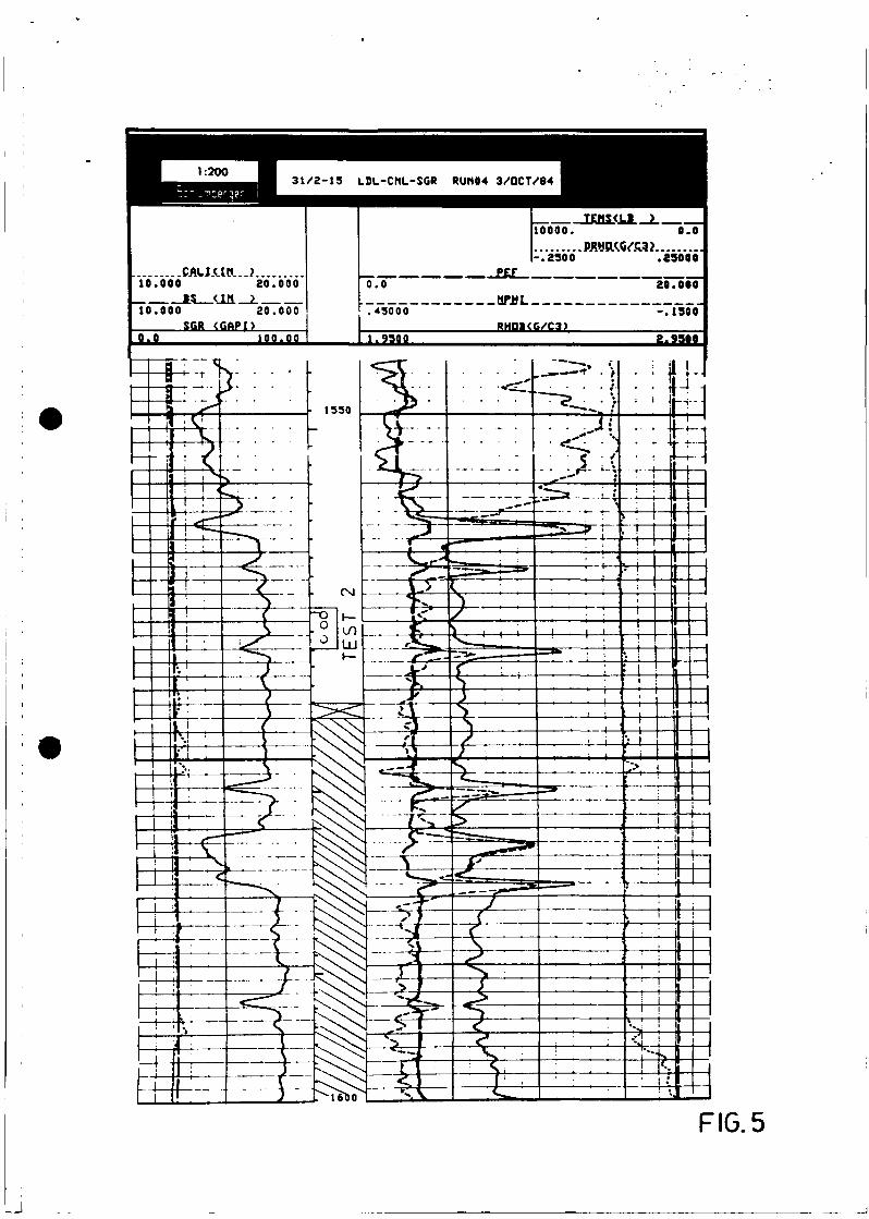
10.000
To~7To~o
.CAU.UtL..}.20.000
aTTVooTSCR <GAPI)
o.o 100.00
TEMSCLi ) ___o ooo. o.o
-.3500per
0.0
.39000
"zoTooo"
.43000.MPML
RHQKG/C3)1.9300 g.930>
FIG. 5
i