ludlum model 52 - ludlum measurements · ludlum model 52 portable portal monitor ... 6.5 person...
TRANSCRIPT

LUDLUM MODEL 52
PORTABLE PORTAL MONITOR
November 2011
Serial No. 175872 and Succeeding
Serial Numbers


LUDLUM MODEL 52
PORTABLE PORTAL MONITOR
November 2011
Serial No. 175872 and Succeeding
Serial Numbers

Model 52 Portable Portal Monitor
November 2011
page i
TABLE OF CONTENTS
1. GENERAL ............................................................................................................................................................. 1
2. ASSEMBLY INSTRUCTIONS ............................................................................................................................ 1
2.1 Packing Instructions ......................................................................................................................................... 3
3. USER OPERATION ............................................................................................................................................. 4
3.1. Operational Check ........................................................................................................................................... 4
3.2. Personnel Monitoring ...................................................................................................................................... 4
4. SPECIFICATIONS................................................................................................................................................ 7
5. DESCRIPTION OF CONTROLS AND FUNCTIONS......................................................................................... 7
6. PARAMETERS AND FUNCTIONS .................................................................................................................... 9
6.1 Alarm Menu Parameters .................................................................................................................................. 9
6.2 Time Menu Parameters .................................................................................................................................... 9
6.3 Volume Menu Parameters ................................................................................................................................ 9
6.4 Background Menu Parameters ......................................................................................................................... 9
6.5 Person Counter .............................................................................................................................................. 10
6.6 Water Resistant Sleeve .................................................................................................................................. 10
6.7 RS-232 Port ................................................................................................................................................... 10
7. SETUP OPERATION ......................................................................................................................................... 12
7.1 Setup Menu ..................................................................................................................................................... 12
7.1.1 Setup Alarm Menu ................................................................................................................................. 12
7.1.2 Setup Background Menu ........................................................................................................................ 12
7.1.3 Setup Time Menu ................................................................................................................................... 14
7.1.4 Setup Volume Menu ............................................................................................................................... 14
7.1.5 Password Menu ...................................................................................................................................... 15
7.2.Read Menu .................................................................................................................................................... 15
7.2.1 Read Alarms Menu ................................................................................................................................. 15
7.2.2 Read Time Menu .................................................................................................................................... 15
7.2.3 Read Volume Menu ............................................................................................................................... 16
7.3 Counts Menu .................................................................................................................................................. 16
8. CALIBRATION PROCEDURE .......................................................................................................................... 16
8.1 General ........................................................................................................................................................... 16
8.2 Equipment Required ....................................................................................................................................... 16
8.3 Calibration Procedure ..................................................................................................................................... 16
PARTS LIST ............................................................................................................................................................... 18
Model 52 Portable Portal Monitor ........................................................................................................................... 18
Main Board, Drawing 215 x 60 ........................................................................................................................... 18
AMP/HVPS Board, Drawing 215 x 82 ................................................................................................................ 19
LED Display, Drawing 215 X 63......................................................................................................................... 20
LED Display Driver, Drawing 420 X 4 ............................................................................................................... 20
Wiring Diagram, Drawing 215 X 116 ................................................................................................................. 20
DRAWINGS AND DIAGRAMS ................................................................................................................................ 21

Model 52 Portable Portal Monitor
November 2011
page 1
1. GENERAL
The Model 52 Portal Monitor is used for Beta/Gamma
personnel contamination monitoring and meets the
FEMA standard for Emergency Response Portal
Monitoring (FEMA-REP-21). It is designed to be
disassembled for ease of transportation and storage,
and can be assembled in five minutes or less without
tools. All parameters are stored in non-volatile
memory, which requires no battery backup. These
parameters allow easy operation with minimal setup by
minimally trained personnel. The parameters are pre-set
at the factory to detect a 1 µCi 137
Cs beta window
source in a 10 µR/hr background field, in accordance
with the FEMA standard. The Model 52 can be
powered by 120 Vac or 6 “D” cell batteries. 220 Vac-
powered units are available as a special order.
The instrument has a “person-counter” integrated into
the electronics that increments by 1 every time a count
is completed. It is a four-digit number normally
displayed on the LCD display, next to the “READY”
message. It also has an RS-232 port that can be used to
print out parameter setpoints, background counts, and
counts above background.
The portal frame incorporates an array of 18 GM
(Geiger-Mueller) detectors positioned around the frame
and base. Fourteen GM pancake detectors are located
in the frame for monitoring the head and body. Four
cylindrical GM detectors are utilized in the base for
monitoring the feet.
The electronics are microprocessor-based for ease of
setup and reliability. Individual LEDs (Light Emitting
Diodes) mounted in the frame and also on the
electronics front panel indicate the specific alarm
location. LEDs in the front panel indicate count cycle
status. Audible signals accompany the LEDs for
additional indication. Detector counts, background, and
all parameters may be viewed on the LCD display. All
setup is accomplished via pushbuttons on the
electronics assembly.
The Model 52 incorporates a summing alarm in
addition to the individual channel alarms. This
increases the system sensitivity to widespread
contamination. If two or more channels have a
noticeable increase in counts, but do not exceed their
alarm threshold, the sum of their counts could exceed
the summing alarm.
The Model 52 also has background update and subtract
capabilities. The instrument will take a background
count and subtract it from the current count. This
function helps compensate for fluctuations in
background. Background subtract can be turned on or
off, and the background count time, and the
background interval time are adjustable. The operator
can force the instrument to stop and take a background
count at a different interval if desired.
The alarm volume is adjustable via the keypad on the
front panel. For further explanation of parameters and
their functions, see Section 6.
2. ASSEMBLY INSTRUCTIONS
SEE FIGURE 1 – MODEL 52 ASSEMBLY DRAWING ON PAGE 2
This section gives instructions on how to assemble
the Model 52 and get it ready for use.
The Model 52 comes in a container that can be used
for shipping and storage. The pieces and quantities
that make up the system are:
1 - Base
1 - R1 (Right #1) Section
1 - R2 Section
1 - R3 Section
1 - L1 Section
1 - L2 Section
1 - L3 Section
1 - Top Section
1 - Electronics Section
1 - Power Cord
1 - Remote electronics extension cable (optional).
Unpack the container and inventory to ensure that all
pieces are present.
The Model 52 can be assembled without tools. All
connections are made with latches. To connect a
latch, lift up the bottom tab, hook the top cross bar
into the hook on the piece that you are attaching, and
push tab back down until it snaps into place.
CAUTION: Exercise care when unlatching
pieces, as the latches can spring open violently.
To unlatch, lift up the tab and unhook the top cross
bar.
Set the Base on the ground with the screens
over the foot detectors facing up.

Model 52 Portable Portal Monitor
November 2011
page 2
Figure 1 – Model 52 Assembly Drawing
Insert the male end of section R1 into the
female side bracket of the base marked
RIGHT and attach the latches. The detector
screens must be facing toward the middle of
the portal.
Insert the male end of section R2 into female
end of section R1 and attach the latches.
Repeat the process for the rest of the side
sections (R3 through L3).
Insert the TOP into the tops of the side
sections and attach the latches. The top can
be installed in either direction. It does not
matter which end goes to the right.
Plug the ELECTRONICS section onto the
back of section R2 with the LEDs facing up.
Make sure that the pin in the back of R2
goes into the hole on the electronics. Then
attach the latches. If you are using the
optional Remote Electronics Extension
Cable, plug it between R2 and the
electronics. Place the electronics wherever
necessary.
If you have line voltage available, plug the
POWER CORD into the connector on the
bottom of the electronics marked INPUT. If
not, install 6 “D” cell batteries into the
battery compartment. The power cord and
batteries may both be installed at the same
time, but the Model 52 does not charge the
batteries.
Turn on the POWER switch located on the
bottom of the electronics and allow the
instrument to finish updating. If the pre-
programmed settings are acceptable, it is
ready for use. Proceed to User Operation,
Section 3. If the settings need to be changed
or checked, proceed to Parameter Setup,
Section 7.

Model 52 Portable Portal Monitor
November 2011
page 3
2.1 Packing Instructions
Figure 2 – Model 52 Packing Instructions

Model 52 Portable Portal Monitor
November 2011
page 4
3. USER OPERATION
This section gives instructions on how to use the
instrument to monitor a person for radiation
contamination. It assumes that the unit has been
assembled and turned on. If this is not the case, refer
to Assembly Instructions, Section 2. For information
on Parameter Setup, see Section 7. The front panel
and top and bottom views are on pages 5 and 6.
3.1 Operational Check
To ensure that the Model 52 is functioning correctly,
an operational check should be performed on a
routine basis. This check verifies that the instrument
is turned on, that the settings are appropriate, and that
the system alarms when the detectors are exposed to
excess radiation (above background level). Ludlum
Measurements suggests that this operational check be
performed once per day or at the beginning of each
work period. As long as the system passes the
operational check, no calibration or other checks are
necessary. If the response or any function of the
Model 52 should change, the instrument should be
checked and brought into compliance with the
manufacturer’s original specifications.
Check each of the eight sections for
sensitivity to radiation. There are 3 sections
on each side, one at the top, and one on the
floor (base plate). Using the check source
supplied with the instrument (137
Cs,
approximately 1 Ci), hold the source as
described on the instrument’s Certificate of
Calibration, with the active side of the
source turned toward the panel to be tested.
Activate the counter by pressing on the base
plate. When the audible beep sounds, the
six-second count time commences. Keep the
source in place with pressure on the base
plate until the alarm sounds. The visual
alarms on the frame and control panel
relevant to that panel should also illuminate.
Remove the source and the pressure on the
base plate to allow the unit to reset. If any of
the appropriate alarms do not activate before
the end of the six-second count (indicated by
another audible beep), the instrument
requires a check to the manufacturer’s
specifications and possible repair.
Repeat alarm checks for all sections. For the
base plate, perform the check on each side,
holding the source as described on the
instrument’s Certificate of Calibration.
To also provide assurance that the
instrument meets the FEMA emergency
response criteria prior to operation of this
portal, do the following: Pass the 1 µCi 137
Cs
check source through the center of the portal
at several points between 0.5 and 5 feet from
the floor of the portal, and verify that the
alarm is triggered each time. If the portal
does not alarm each time, the user may need
to adjust the count time, the alarm points, or
move the portal to a location with lower
background radiation.
3.2 Personnel Monitoring
A count starts when someone steps onto the base
plate. A count can only be started when the system is
in the READY mode. You must exit out of any
setup menus before a count can be taken.
Prior to operation, the monitor must be allowed to
update the background count if background time is
not set to zero. This mandatory update occurs just
after power-up and then after expiration of the
background update interval timer. New background
count data is compared to the low and high-
background set points that have been programmed
into the unit. If the set points have been exceeded, a
HI BACKGROUND or LO BACKGROUND alarm
is given and the unit returns to updating background.
The instrument will continue to update the
background until the alarm condition has been
corrected, i.e. the background goes down, failed
detectors are repaired, or the parameters have been
changed.
To check someone for radiation contamination,
follow the steps below:
The green READY light must be lit in order
to use the instrument. An orange
UPDATING light may be on, indicating that
a standby update is taking place. When the
UPDATING light is on, the system should
not be used and all people to be checked
should remain at least 0.91 m (3 ft) away
until the READY light comes back on.
The subject steps onto the base plate and
positions feet on the foot detector screens.
The green COUNTING light will come on.
The yellow INCOMPLETE light will turn
on if the subject steps off of the base plate
before the count is complete.
When the count is complete, the green

Model 52 Portable Portal Monitor
November 2011
page 5
CHECK OK light or one or more of the red
alarm lights will turn on. If there is an alarm,
the alarm LEDs on the top of the electronics
and the LEDs on the portal frame will
indicate the location of the alarm.
The subject then steps off the instrument.
Figure 3 – Model 52 Front Panel Drawing

Model 52 Portable Portal Monitor
November 2011
page 6
Figure 4 – Model 52 Electronics Top View
Figure 5 – Model 52 Electronics Bottom View

Model 52 Portable Portal Monitor
November 2011
page 7
4. SPECIFICATIONS
FUSE: Littelfuse F-1A, 1 amp, 5 x 20 mm, 250 volt
COUNTING CAPACITY: 9999 counts per minute
SENSITIVITY: 80 mV
COUNT TIME: adjustable from 1 to 60 seconds
ALARM HOLD TIME: adjustable from 1 to 99
seconds
BACKGROUND UPDATE INTERVAL:
automatic, adjustable from 0-99 minutes, 0 = OFF
BACKGROUND COUNT TIME: adjustable from
0-99 seconds, 0 = OFF
FORCE BACKGROUND UPDATE INTERVAL
TIME: adjustable from 0 to 99 minutes, 0 = OFF.
PERSON COUNTING CAPACITY: 9999 people
before rolling back to zero.
SETUP PASSWORD: four-digit numeric password
that, if enabled, must be entered before having access
to the setup menu.
AUDIO: unimorph speaker with keypad adjustable
volume
POWER: 95-135 Vac (178-238 VAC available),
50/60 Hz, 50 watts maximum or six (6) “D” cell
batteries. Battery life is approximately 80 hours in a
non-alarm condition.
OUTSIDE DIMENSIONS: 206 x 102 x 63 cm (81 x
40.3 x 24.8 in.) (H x W x D)
INSIDE DIMENSIONS: 194 x 81.3 cm (76.5 x 32
in.)
WEIGHT: 29.5 kg (65 lb) (38.6 kg [85 lb] including
case)
5. DESCRIPTION OF CONTROLS AND FUNCTIONS
FRONT PANEL - (See Figure 3 on page 5)
READOUT: LCD, 1-line, 16-character
alphanumeric display. It normally displays
“ READY ” “XXXX,” with the
“XXXX” being the number of people who
have been checked by the instrument. It will
display other messages, depending upon the
operational status of the instrument. Counts,
alarms, and other information can be
displayed by following the instructions in
Section 7.
EXIT Key: moves back one menu selection.
Increment (Up Arrow “”) Button:
moves up one line in the current menu.
WITHIN PARAMETER SETUP: A digit
increments by 1. An on/off parameter
toggles to the other state.
Decrement (Down Arrow “”) Button:
moves down 1 line in the current menu.
WITHIN PARAMETER SETUP: A digit
decrements by 1. An on/off parameter
toggles to the other state.
SELECT Key: selects the current menu
displayed on the readout. When setting
parameters, it activates the digits so that they
can be changed.
SAVE Key: recessed pushbutton that saves
all parameters to non-volatile memory. This
button can only be operated by inserting a
small screwdriver or pin through the hole.
All of the microprocessor RAM is
transferred to EEPROM memory when this
button is pushed. Any changes made to
variables only change the current
microprocessor RAM. If the Model 52 is
turned off prior to saving changes, the
changes are lost. To save parameter changes,
press the SAVE button before turning the
Model 52 off. Upon power-up, the
EEPROM memory is loaded into the
microprocessor. If the SAVE key is pressed
while turning the instrument on, the Model
52 is loaded with a set of default parameters.

Model 52 Portable Portal Monitor
November 2011
page 8
The parameters that are set are:
Default Value
Count time 6 sec
Background Count Time 60 sec
Update Interval 5 min
Force Background 30 min
Hold Time 6 sec
Alarm Volume 255
Password On/Off OFF
Password 0000
Alarms
Left 200
Right 200
Head 200
Feet 250
Sum 450
Background Alarms
Left Low/High 25/1000
Right Low/High 25/1000
Head Low/High 25/1000
Feet Low/High 50/1000
.
LEDs (top of electronics) - (See Figure 4 on page 6
for LED layout)
READY LED: normally lit prior to any
interrogation. System is ready to take a
count.
COUNTING LED: indicates that a count is
in progress. Stepping off of the base plate
prior to expiration of the count time will
cause this light to go off and the
INCOMPLETE LED to come on. When the
count is complete, the CHECK OK or one
of the alarm LEDs will activate.
CHECK OK LED: indicates that a count
has been completed and no alarms were
sensed. This LED will stay on until the
subject steps off of the base plate or for 2
seconds, whichever is longest.
INCOMPLETE LED: indicates that a count
was in progress and the subject stepped off
of the base plate before the count was
complete. The Incomplete LED stays on for
the alarm hold time or until the subject steps
back onto the base plate. An incomplete
resets the count time. If no one steps back
onto the base plate during the incomplete
time, then the Model 52 goes back to the
ready state, lighting the READY LED.
LO BAT / TROUBLE LED: indicates that
the batteries are weak and must be replaced.
It can also indicate that the system has
detected a high or low-background
condition. If there is a background problem,
the UPDATING LED will also be lit and
the LCD display will have a message
displayed. If the batteries are weak, the LO
BAT/TROUBLE LED will be the only
LED illuminated. Battery condition will not
be indicated when the system is connected to
line voltage.
SUM ALARM, HEAD, etc. LEDs:
indicate which channel has alarmed during a
count. These light as soon as an alarm is
sensed; when the count is complete, the
CHECK OK will not light, the audio will
stay on for the alarm hold time, and then the
Model 52 goes back to the ready state,
lighting the READY LED. The SUM
ALARM is an alarm that adds all the
channels together to determine if there is
widespread contamination. If several
channels have a high count but not high
enough to exceed their individual alarm
threshold, then the sum of the channels could
exceed the sum alarm threshold.
BOTTOM OF ELECTRONICS - (See Figure 5 on
page 6)
Power On/Off: switch to turn instrument on
and off. Switches both line voltage and
batteries.
Line Fuse: fuse to limit current from AC
outlet. The fuse is a Littelfuse F 1A or
equivalent.
INPUT: line voltage input, 115 Vac, 50/60
Hz, 50 W.
6 “D” CELLS (underneath door):
compartment for batteries. Holds 3 “D” cell
batteries per side. Install batteries as shown
by diagram above holes.
RS-232: necessary for instrument to be
connected to a printer or a computer.

Model 52 Portable Portal Monitor
November 2011
page 9
6. PARAMETERS AND FUNCTIONS
This section lists the different parameters of the
Model 52 and their functions.
All counts, alarms, and other settings are in
COUNTS PER MINUTE. The instrument makes the
necessary calculations to convert the count time
setting into counts per minute.
The READ menu accesses the same parameters and
in the same way as the SETUP menu. However, no
parameters may be changed in the READ menu.
The COUNTS menu shows the accumulated counts
in each channel.
6.1 Alarm Menu Parameters
ALARMS - This parameter sets the number of
counts per minute that it takes to set off an
alarm. If background subtract is turned on, the
alarm will be the number of counts above
background. If it is turned off, the alarm will be
the number of gross counts. All channels must
have their alarms individually set. An alarm can
be turned off by setting it to zero.
LO BACKGROUND ALARM - This
parameter sets the number of counts per minute
that the background should not fall below in
normal operation. If background falls below this
level, a LO BACKGROUND alarm will be
signified by a message on the LCD and
illumination of the UPDATING light and the LO
BAT/TROUBLE light. This alarm indicates if a
detector has failed or is not connected. This
alarm will also indicate if the ambient
background has gone down. All channels must
have their LO BKGND Alarms individually set,
and each can be turned off by setting it to zero.
HI BACKGROUND ALARM - This alarm is
the opposite of the LO BACKGROUND alarm.
This alarm will indicate if background radiation
has increased or if a detector has failed. All
channels must be set individually and each can
be turned off by setting to zero.
6.2 Time Menu Parameters
COUNT TIME - This parameter sets the length
of time in seconds that the instrument will
accumulate counts before determining if a
subject is contaminated. Its range is 1 to 60
seconds.
ALARM HOLD TIME - This sets the length of
time in seconds that visual and audible alarm
signals will stay on before the instrument goes
back to the READY mode. All alarms and
INCOMPLETE are controlled by this timer.
6.3 Volume Menu Parameters
ALARM VOLUME - This sets the volume
of the audible alarm signal. Setting range is
from 1 (lowest) to 255 (loudest). Audio can
be turned off by setting to zero.
6.4 Background Menu Parameters
BACKGROUND SUBTRACT ON/OFF -
This allows you to turn the background
subtract function on or off.
BACKGROUND COUNT TIME - This
sets the length of time in seconds the
instrument will accumulate counts to
determine background. The instrument takes
the last three background counts and
averages them to determine background. The
setting range is from 0 to 99 seconds. If
BACKGROUND COUNT TIME is set to
zero, no background will ever be taken. This
includes the initial background taken at
startup.
BACKGROUND INTERVAL - This sets
the length of time in minutes that the
instrument will wait before taking another
background count. After the time has
elapsed, the instrument will attempt to take a
background count. The setting range is from
0 to 99 minutes. Zero is off. If something
interrupts it during the count (someone steps
on the base plate, changes a parameter, etc.),
the count is aborted and the instrument will
try again as soon as it returns to the READY
mode. During heavy usage, it is possible that
the instrument may never be able to
complete a background count. After a
background count has been taken, the
INTERVAL and FORCE INTERVAL
timers are reset. If BACKGROUND
INTERVAL is set to zero, the background
will never be updated after the initial startup
background.
FORCE BACKGROUND INTERVAL -
This sets the length of time in minutes the
instrument will wait before it shuts down

Model 52 Portable Portal Monitor
November 2011
page 10
operation and forces you to allow it to take a
new background count. The setting range is
from 0 to 99 minutes. During heavy usage,
the normal background interval may not be
able to take a background count. The
FORCE interval will cause the instrument to
shut down until it has had a chance to update
background. This time interval must always
be larger than the BACKGROUND
INTERVAL or the COUNT TIME. After a
background count has been taken, the
INTERVAL and FORCE INTERVAL
timers are reset.
6.5 Person Counter
The Person Counter is built into the Model
52 electronics so that the operator can keep
track of the number of people who have
been surveyed by the instrument. It is also
printed out with the counts to help keep
track of which person was contaminated.
The counter is displayed on the LCD along
with the READY message. The counter can
be reset by turning the instrument off and
then back on.
6.6 Water Resistant Sleeve
In order to provide a degree of protection
against rain, a water resistant sleeve is
available for the instrument. To install,
simply slide the sleeve over the bottom R1
section before installing the rest of the
sections. After all detector sections have
been installed, stretch the sleeve over all
sections. Cut a hole in the sleeve over the
connector for the electronics. Slide a short
piece of sleeving over the electronics, and
cut a hole over that connector as well. Fold
the sleeve over the top of the electronics,
and then attach the electronics to the
detector section. Proceed with operation of
the instrument.
.
6.6 RS-232 Port
The RS-232 port allows the instrument to be
connected to a printer or a computer so that
a record can be kept of the activity of the
instrument
When connected to a printer - When the
instrument is first turned on, the printer will
print the parameter settings. From then on,
when a count is complete, the printer will
print out the person number, the background
counts, and the number of counts above
background for all channels. Check OK or
Alarm will be printed with an asterisk beside
any channel that has exceeded its alarm set
point. See the examples below.
When connected to a computer – The
instrument will send the same data to a
computer that it sends to a printer (see
above). The optional computer software will
display the data on the screen and allow it to
be saved to a file.
See following page for examples of RS-232 port
printouts.

Model 52 Portable Portal Monitor
November 2011
page 11
The Model 52 RS-232 port operates at 9600 baud, 8 data bits, 1 stop bit, no parity (9600,8,N,1).
Example printout from the RS-232 port after power-on. LUDLUM MEASUREMENTS, INC.
MODEL 52 PORTAL MONITOR
PARAMETER LIST
COUNT TIME = 006 SEC
BACKGROUND COUNT TIME = 060 SEC
UPDATE INTERVAL = 005 MIN
FORCE BACKGROUND = 060 MIN
HOLD TIME = 006 SEC
ALARM VOLUME = 255
SECTION ALARM POINT LO COUNT HI BKGND
L1 0200 0000 1000
L2 0200 0000 1000
L3 0200 0000 1000
R1 0200 0000 1000
R2 0200 0000 1000
R3 0200 0000 1000
FEET 0250 0000 1000
HEAD 0200 0000 1000
SUM 0450
ALL COUNTS IN CPM.
Example printout from the RS-232 port after a complete count. PERSON # 0001
CHECK OK
SECTION BACKGROUND COUNT ABOVE BKGND ALARM
L1 0079 0000 NO
L2 0087 0000 NO
L3 0071 0009 NO
R1 0085 0000 NO
R2 0089 0051 NO
R3 0072 0000 NO
FEET 0252 0000 NO
HEAD 0072 0000 NO
SUM 0807 0060 NO
ALL COUNTS IN CPM.

Model 52 Portable Portal Monitor
November 2011
page 12
7. SETUP OPERATION
SEE FIGURE 6 on page 13 for menu diagram.
This section gives instructions on how to use the keys
to set up the instrument. Examples of keystroke
sequences are given for several parameters. Use the
menu tree diagram and similar keystrokes to access
other parameters. For information on using the
instrument to make a radiation check, see Section 3.
To move from one level of the menu tree to a sub-
level, press the SELECT key. To move up one level,
press the EXIT key. To step through the different
items on one level, use the UP or DOWN ARROW
KEYS. The SELECT key also moves from one digit
to the next when setting parameters.
To reset all parameters to their default settings, hold
down the SAVE key while turning on the instrument.
All parameters are listed in the following order: L1,
L2, L3, R1, R2, R3, FEET, HEAD, and SUM.
When you press the SELECT key from READY
Mode, you have the following selections.
1 - Setup Menu
2 - Read Menu
3 - View Counts Menu
7.1 Setup Menu
The setup menu has four choices:
1- Setup ALARMS MENU
2- Setup BACKGROUND MENU
3- Setup TIME MENU
4- Setup VOLUME MENU
5- Setup PASSWORD MENU
To change a parameter, access the variable of interest
through the setup menus using the SELECT and
increment/decrement “/” keys. Press the SELECT
key to change the parameter. The cursor becomes
visible and blinks on the variable to change. On
multiple digit variables, press the SELECT key to
access the next digit.
7.1.1 Setup Alarms Menu
The SETUP ALARMS menu allows changes to
be made to the count alarms for each of the Individual
Alarm channels.
To access the SETUP ALARM menu:
Turn the instrument ON. Wait for READY
to display on the LCD.
Press SELECT once to select the setup
menu. SETUP menu appears.
Press SELECT once to execute the setup
menu. ALARMS menu appears.
Press SELECT once to execute the alarms
menu. L1 ALARM XXXX appears where
XXXX is a four-digit number between 0 and
9999. To access other alarm channels, use
the increment (“” or decrement “”) keys.
To change the current setting, press
SELECT to activate the first digit. Use
increment/decrement “/” to change the
first digit as desired. Press SELECT to
activate the second digit. Use
increment/decrement “/” to change the
second digit as needed. Repeat for the other
digits. Press SELECT to temporarily save
the settings.
Repeat the above step to change the other
alarm channels as desired.
Press the EXIT key to exit back to the
ALARMS menu.
NOTE: Press the SAVE key in order to put
parameters in non-volatile memory before
powering down.
7.1.2 Setup Background Menu
Access the SETUP menu:
Ensure READY displayed on LCD.
Press SELECT once to select the setup
menu. SETUP menu appears.
Press SELECT once to execute the setup
menu. ALARMS menu appears.
Press decrement “” once to advance to the
BACKGROUND MENU.

Model 52 Portable Portal Monitor
November 2011
page 13
Figure 6 – Model 52 Menu Tree Diagram

Model 52 Portable Portal Monitor
November 2011
page 14
Press SELECT once to activate the
BACKGROUND menu.
Press SELECT and use either the increment
or decrement (“” or “”) key to toggle the
back-ground subtract feature ON or OFF as
desired. This will normally be left in the ON
position. Activate and exit the ON/OFF
prompt by pressing the SELECT key one
last time.
Press the decrement “” key to select the
BKGROUND TIME.
Note: This number must be less than or
equal to the FORCE UPDATE and BKGND
UPD INT parameter as set above.
Press the decrement “” key to select the
BKGND UPD INT timer. Save and exit this
item by pressing the SELECT key one time.
Note: This parameter must be greater than
or equal to the BKGROUND TIME
parameter and less than or equal to the
FORCE UPDATE parameter.
Press the decrement “” key to move to the
FORCE UPDATE interval timer. Press the
SELECT key to edit this timer as desired.
The FORCE INTERVAL must always be
larger than the BKGND UPD INT and the
BKGND TIME. Save and exit this menu
item by pressing the SELECT key one last
time.
7.1.3 Setup Time Menu
This menu sets the count time and alarm hold time.
The alarm hold time also applies to the Incomplete
LED.
To access the SETUP TIME menu:
Ensure READY displayed on the LCD.
Press SELECT once to select the setup
menu. SETUP menu appears.
Press SELECT once to execute the setup
menu. ALARMS menu appears.
Press the decrement “” key twice. TIME
menu appears.
Press SELECT once to execute the setup
time menu. “COUNT TIME XX” appears.
The “XX” is a number between 1 and 60.
Press SELECT to activate the first digit. Use
increment/decrement “/” keys to change
the first digit. Press SELECT to activate the
second digit. Use increment/decrement
“/” to change the second digit. Press
SELECT to temporarily save parameter.
Use increment/decrement “/” to change
to the next setting.
Press the EXIT key to exit back to the TIME
menu.
NOTE: Press the SAVE key in order to store
parameters in non-volatile memory prior to
power down.
7.1.4 Setup Volume Menu
The volume menu sets the alarm volume. The Model
52 emits a beeping sound after various events (mode
change, parameter change, etc.). This beeping volume
is always at the maximum and is not adjustable.
To access the SETUP VOLUME menu:
Ensure “READY” is displayed on LCD.
Press SELECT once to select the setup
menu. SETUP menu appears.
Press decrement “” three times to get to
the VOLUME MENU.
Press SELECT once to execute the setup
volume menu. “ALARM VOLUME XXX”
appears. The “XXX” is a number between 1
and 255. This variable sets from 001
(lowest) to 255 (loudest). A value of 000
mutes the audio alarm volume. Any audio
alarm uses this volume set point. The beep
audio is not affected by this setting.
Press SELECT to activate the first digit. Use
increment/decrement “/” to change the
first digit. Press SELECT to activate the
second digit. Use increment/decrement
“/” to change the second digit. Repeat
for third digit. Press SELECT to save.
Press the EXIT key to exit back to the
VOLUME menu.
NOTE: Press the SAVE key in order to store
parameters in non-volatile memory prior to power-
down.
Model 52 Portable Portal Monitor
November 2011
page 15
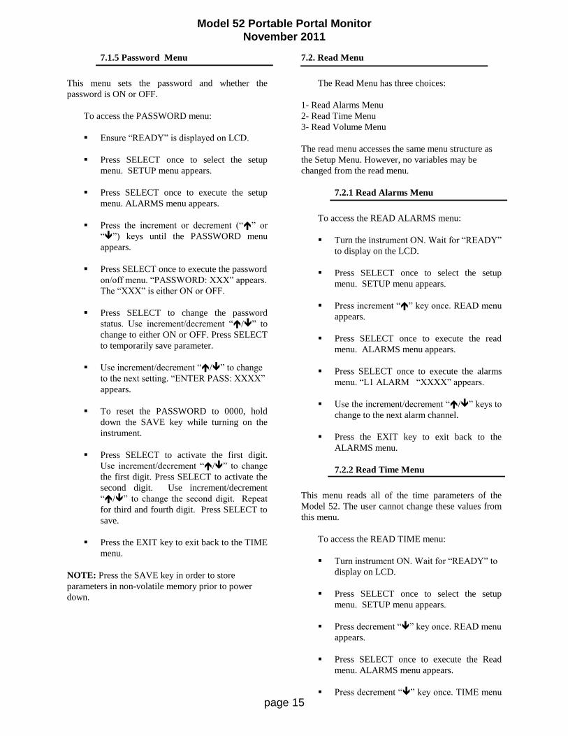
7.1.5 Password Menu
This menu sets the password and whether the
password is ON or OFF.
To access the PASSWORD menu:
Ensure “READY” is displayed on LCD.
Press SELECT once to select the setup
menu. SETUP menu appears.
Press SELECT once to execute the setup
menu. ALARMS menu appears.
Press the increment or decrement (“” or
“”) keys until the PASSWORD menu
appears.
Press SELECT once to execute the password
on/off menu. “PASSWORD: XXX” appears.
The “XXX” is either ON or OFF.
Press SELECT to change the password
status. Use increment/decrement “/” to
change to either ON or OFF. Press SELECT
to temporarily save parameter.
Use increment/decrement “/” to change
to the next setting. “ENTER PASS: XXXX”
appears.
To reset the PASSWORD to 0000, hold
down the SAVE key while turning on the
instrument.
Press SELECT to activate the first digit.
Use increment/decrement “/” to change
the first digit. Press SELECT to activate the
second digit. Use increment/decrement
“/” to change the second digit. Repeat
for third and fourth digit. Press SELECT to
save.
Press the EXIT key to exit back to the TIME
menu.
NOTE: Press the SAVE key in order to store
parameters in non-volatile memory prior to power
down.
7.2. Read Menu
The Read Menu has three choices:
1- Read Alarms Menu
2- Read Time Menu
3- Read Volume Menu
The read menu accesses the same menu structure as
the Setup Menu. However, no variables may be
changed from the read menu.
7.2.1 Read Alarms Menu
To access the READ ALARMS menu:
Turn the instrument ON. Wait for “READY”
to display on the LCD.
Press SELECT once to select the setup
menu. SETUP menu appears.
Press increment “” key once. READ menu
appears.
Press SELECT once to execute the read
menu. ALARMS menu appears.
Press SELECT once to execute the alarms
menu. “L1 ALARM “XXXX” appears.
Use the increment/decrement “/” keys to
change to the next alarm channel.
Press the EXIT key to exit back to the
ALARMS menu.
7.2.2 Read Time Menu
This menu reads all of the time parameters of the
Model 52. The user cannot change these values from
this menu.
To access the READ TIME menu:
Turn instrument ON. Wait for “READY” to
display on LCD.
Press SELECT once to select the setup
menu. SETUP menu appears.
Press decrement “” key once. READ menu
appears.
Press SELECT once to execute the Read
menu. ALARMS menu appears.
Press decrement “” key once. TIME menu
Model 52 Portable Portal Monitor
November 2011
page 16
appears.
Press SELECT once to execute the time
menu. “COUNT TIME XX” appears. The
“XX” is a number between 0 and 99.
Use the increment/decrement “/” keys to
change to other time parameters.
Press the EXIT key to exit back to the TIME
menu.
7.2.3 Read Volume Menu
This menu reads all of the volume parameters of the
Model 52. The user cannot change these values from
this menu.
To access the READ VOLUME menu:
Turn the instrument ON. Wait for “READY”
to display on LCD.
Press SELECT once to select the setup
menu. SETUP menu appears.
Press decrement “” key once. READ menu
appears.
Press SELECT once to execute the read
menu. ALARMS menu appears.
Press decrement “” key twice. VOLUME
menu appears.
Press SELECT once to execute the time
menu. “ALARM VOLUME XXX” appears.
The “XXX” is a number between 0 and 255.
Use the increment/decrement “/” keys to
change to other parameters.
Press the EXIT key to exit back to the
VOLUME menu.
7.3 Counts Menu
The counts menu will display the counts for each
channel, one channel at a time.
Use the increment/decrement “/” keys to change
to the next channel.
8. CALIBRATION PROCEDURE
8.1 General
The Model 52 is set for 80 mV sensitivity and 900
Vdc operation for GM type detectors.
8.2 Equipment Required
Ludlum Model 500 Pulser or equal
High-impedance voltmeter for high-voltage
measurements (1000 megohm)
8 to 15 volt DC power supply
Digital counter or oscilloscope for negative
going 5 Vdc pulses
8.3 Calibration Procedure
Calibration of the Model 52 is accomplished by
adjustments to the amplifier board located inside each
detector section of the portal frame. Adjustments
include threshold voltage level and the high-voltage
power supply setting. The design threshold level is 80
mV and operating high voltage is approximately 900
Vdc.
The amplifier board has two eight-position DIP
switches. The switch in line with the 10 pin MTA is
used to select the LED connection, and the switch in
line with the 14-pin MTA is used to select the signal
connection. To set the switches for the section that
the board will be used in, close the corresponding
channel as listed below and open all others:
L1 - SWITCH 1
L2 - SWITCH 2
L3 - SWITCH 3
R1 - SWITCH 4
R2 - SWITCH 5
R3 - SWITCH 6
FOOT - SWITCH 7
HEAD - SWITCH 8

Model 52 Portable Portal Monitor
November 2011
page 17
Connect the center conductor of a cable
from the Model 500 Pulser to one of the
Teflon-insulated connector jacks and
ground to the metal sockets. Apply
power to the board by supplying +12
Vdc to Pin 13 of one of the 14 pin MTA
connectors and ground to pin 14.
You may use a voltage from 8 to 15
volts on pin 13. Pin 1 of the connector is
defined as the pin on the right as you
face the pins with the white tab on the
other side of the pins. Pin 1 goes to
switch 1 on the dip switches
Attach the counter or oscilloscope to
one of pins 1 through 8 of the 14-pin
MTA connectors, connected to a closed
switch. Adjust pulser amplitude to
negative 80 mV and vary R1123 (THS)
until pulses just appear.
Adjust R194 (HV ADJUST) for 900
Vdc at the Teflon-insulated connector
jack.

Model 52 Portable Portal Monitor
November 2011
page 18
PARTS LIST
Ref. No. Description Part No.
Model 52 Portable Portal Monitor
UNIT Completely Assembled Model 52
Portable Portal Monitor 48-2471
Main Board, Drawing 215 x 60
BOARD Completely Assembled
Main Board 5215-087
CAPACITORS
C101 68F 6.3V 04-5654
C201 68F 6.3V 04-5654
C211 0.1F 50V 04-5663
C231 0.01F 50V 04-5664
C301 2700F 35V 04-5621
C311, C312 27pF 100V 04-5658
C501 68F 6.3V 04-5654
C502 0.1F 50V 04-5663
C503 10F 20V 04-5655
C504-C506 0.1F 50V 04-5663
C601 10F 20V 04-5655
C602 4.7F 20V 04-5653
C603 10F 20V 04-5655
C611 4.7F 20V 04-5653
C701 0.1F 50V 04-5663
C711 0.1F 50V 04-5663
DIODES
CR101-CR103 CXSH-4 EB33 07-6358
TRANSISTORS
Q211 MMBT4403LT1 05-5842
Q401 2N7002L 05-5840
Q402 MMBT4403LT1 05-5842
Q501 MMBT3904T 05-5841
RESISTORS
R031 4.75k 12-7858
R111 100k 12-7834
R131-R139 2.21k 12-7835
R211, R212 10k 12-7839
R231 100k 12-7834
R331 22.1k 12-7843
R401 10k 12-7839
R402 10 OHM 12-7836
Ref. No. Description Part No.
R403 10k 12-7839
R431 10k 12-7839
R501 10k 12-7839
R502 10 MEG 12-7955
R503 73.2k 12-7895
R504 10k 12-7839
R505 82.5k 12-7849
R506 1M 12-7844
R507 8.25k 12-7838
R508 10k 12-7839
R701 5 k TRIMMER 09-6918
R1310 100k 12-7834
RESISTOR NETWORK
RN031 NETWORK-4.7 K 12-7918
RN121 NETWORK-4.7K 8P SIP 12-7706
RN331 NETWORK-4.7 K 12-7918
RN421 NETWORK-22 K 12-7917
SWITCHES
S111 92-851.342 ELEMENT 08-6726
S121 92-851.342 ELEMENT 08-6726
S211 92-851.342 ELEMENT 08-6726
S221 92-851.342 ELEMENT 08-6726
S321 92-851.342 ELEMENT 08-6726
TRANSFORMERS
T401 XFMR- M 177 AUDIO 4275-083
INTEGRATED CIRCUITS
U121 22K DIP 14 PIN 12-7577
U122 LTC1045CN 06-6371
U131 TLC372ID 06-6290
U211 X24C02S8I 06-6299
U231-U233 TLC372ID 06-6290
U311 N87C51FA 06-6286
U331 TLC372ID 06-6290
U421 CD74HC573M 06-6298
U431 N82C54 06-6309
U501 LM358D 06-6312
U502 LM285M-2.5 06-6291
U511 CXK581000AM-70LL 06-6385
U531 N82C54 06-6309
U601 MAX232CSE 06-6382
U611 CD74HC138M 06-6339
U612 CD74HC00M 06-6308
U631 N82C54 06-6309
U711 CD74HC08M 06-6313

Model 52 Portable Portal Monitor
November 2011
page 19
Ref. No. Description Part No.
VOLTAGE REGULATOR
VR201 LT1129CQ-5 06-6372
CRYSTALS
Y311 6.144MHZ 01-5262
MISCELLANEOUS
SOCKET 822276-1 44P 06-6293
5 EA. 92-960-0 MTG FLNGE 08-6727
P14 CONN-640456-2 13-8073
P15 CONN-640456-6 13-8095
P16 CONN-640456-3 13-8081
P17 CONN-640456-5 13-8057
P18 CONN-640456-3 13-8081
P19 CONN-1-540456-1 13-8059
P20 CONN-1-640456-4 13-8141
AMP/HVPS Board, Drawing 215 x 82
BOARD Completely Assembled
AMP/HVPS Board 5215-130
CAPICITORS
C111 10F 04-5592
C119 1F 04-5575
C125 0.1F 04-5521
C129 100F 04-5576
C131 100pF 04-5532
C132 0.001F 04-5519
C140 100pF 04-5532
C142 0.0056F 04-5522
C143 0.0047F 04-5547
C151, C152 0.0047F 04-5547
C153 0.01F 04-5523
C163 0.001F 04-5519
C166 0.01F 04-5523
C167 100F 04-5576
C171 1F 04-5607
C172 0.0047F 04-5570
C174 0.0047F 04-5547
C177 0.0047F 04-5547
C187 10F 04-5592
C231 0.01F 04-5523
C233 22F 04-5594
Ref. No. Description Part No.
DIODES
CR118 1N4007 07-6274
CR134 1N4148 07-6272
CR173 1N4007 07-6274
CR175, CR176 1N4007 07-6274
CR225 1N4001 07-6268
TRANSISTORS
Q123 2N3904 05-5755
Q133 MPSW01 05-5778
Q230 2N3904 05-5755
Q256 MPS6534 05-5763
RESISTORS
R110 1 M 10-7028
R113, R114 1 M 10-7028
R115 10k 10-7016
R116 8.2k 10-7015
R141 200 OHM 10-7006
R144 1 G 12-7686
R145 10k 10-7016
R146 22k 10-7070
R159 10k 10-7016
R160 1k 10-7009
R161 4.7k 10-7014
R162 1k 10-7009
R164, R165 100k 10-7023
R170 1k 10-7009
R178 432k 12-7689
R179 100k 10-7023
R180 10k 10-7016
R217 22k 10-7070
R218 100 OHM 10-7004
R219 10k 12-7540
R220 7.15k 12-7620
R222 33k 10-7019
R223 47k 10-7020
R224 100k 10-7023
R229 470k 10-7026
R241 1 M 10-7028
R242 100k TRIMMER 09-6829
R244 1 M TRIMMER 09-6778
R245 4.7k 10-7014
R247 56 OHM 10-7096
SWITCHES
S252, S253 76SB08S DIP 08-6549

Model 52 Portable Portal Monitor
November 2011
page 20
Ref. No. Description Part No.
INTEGRATED CIRCUITS
U181 TLC372I 06-6265
U186 CA3096 06-6023
U211 LM358 06-6024
U235 LM385Z-1.2 05-5808
VOLTAGE REGULATOR
VR236 LM78L05 05-5815
TRANSFORMERS
T2 L8050 40-0902
MISCELLANEOUS
DS257 E176 RED JUMBO 07-6362
P13-P15 CONN-1-640456-4
MTA-100 13-8141
P16-P18 CONN-1-640456-0
MTA-100 13-8066
P-19 CONN-640456-2
MTA-100 13-8073
* RECEPTACLE (7 ea)
Cloverleaf 011-6809 18-8771
LED Display, Drawing 215 X 63
BOARD Completely Assembled
LED Display Board 5215-090
LEDS
DS110 E118-RED 07-6308
DS111 E119-ORANGE 07-6343
DS112 E120-YELLOW 07-6309
DS113, DS114 E121-GREEN 07-6310
DS115 E178-GRN JUMBO 07-6364
DS116-DS124 E112-RED 07-6390
CONNECTORS
P8 CONN-CJ50-36B-10 13-8730
P9 CONN-640456-7
MTA-100 13-8115
LED Display Driver, Drawing 420 X 4
BOARD Completely Assembled
Display Driver Board 5420-005
Ref. No. Description Part No.
RESISTORS
R148 200 OHM 10-7006
R149-R151 10k 10-7016
RESISTOR NETWORK
RN142-R144 150 OHM DIP 16P 12-7741
INTEGRATED CIRCUITS
U140, U141 SN75512 06-6369
Wiring Diagram, Drawing 215 X 116
SWITCHES
S1 DM62J12S205PQ W/LE 08-6715
TRANSFORMER
T1 CFP302 115/230V 22-9908
CONNECTORS
J1 CONN-640440-6
MTA100 13-8047
J2 CONN-640442-3
MTA100 13-8135
J3 CONN-640442-2
MTA100 13-8178
J4, J11 CONN-640442-5
MTA100 13-8140
J5 CONN-1-640442-4
MTA100 13-8173
J6 CONN-640441-3
MTA100 13-8160
J7 CONN-1-640442-1
MTA100 13-8137
J9 CONN-640442-7
MTA100 13-8172
J14 D RECPT-9 PIN 13-8003
J15 CONN-1-640442-4
MTA100 13-8173
MISCELLANEOUS
DSO1 UNIMORPH 21-9251
J13 AC RECEPTACLE 13-8427

Model 52 Portable Portal Monitor
November 2011
page 21
DRAWINGS AND DIAGRAMS
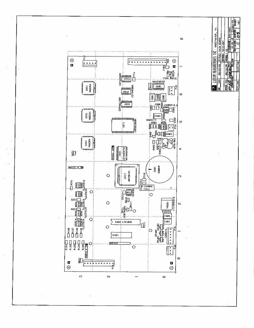
Main Board, Drawing (2 sheets), 215 X 60
Main Board Layout, Drawing 215 X 103
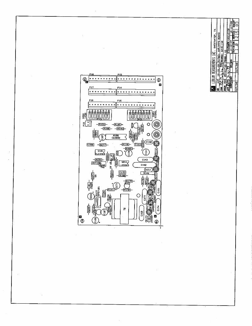
AMP/HVPS Board, Drawing 215 X 82
AMP/HVPS Board Layout, Drawing 215 X 83
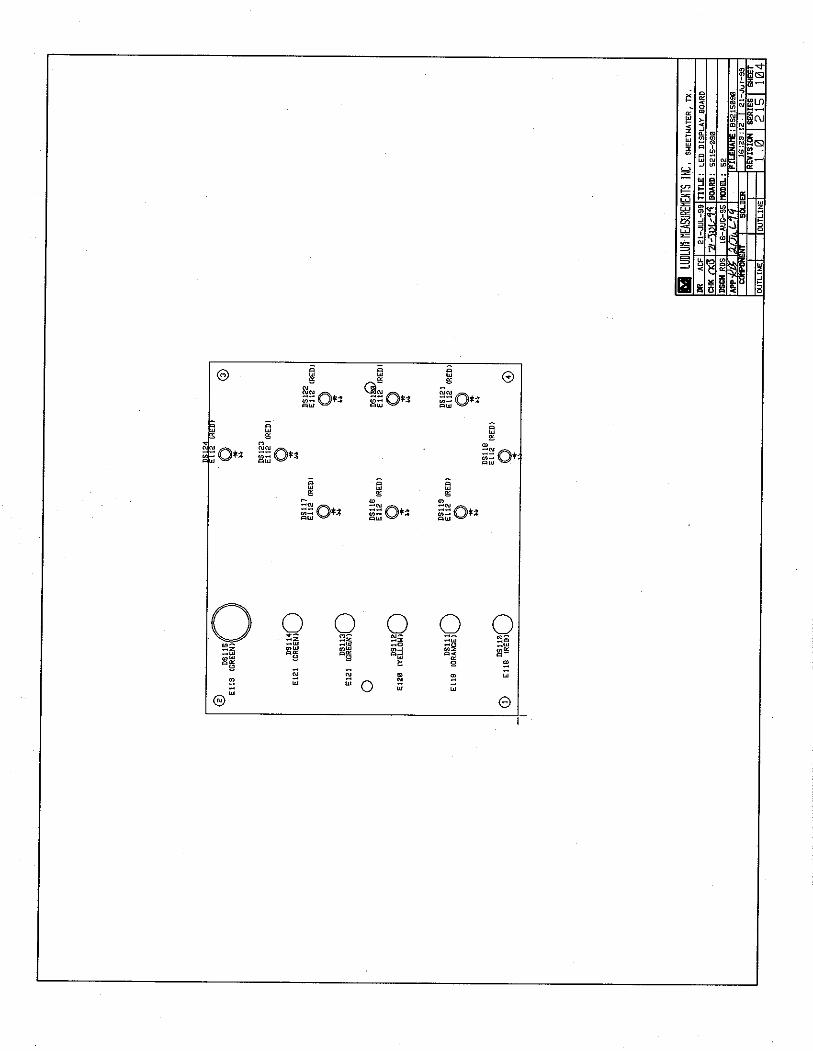
LED Display, Drawing 215 X 63
LED Display Board Layout, Drawing (2 sheets), 215 X 104
LED Display Driver, Drawing 420 X 4
LED Driver Layout, Drawing 420 X 89
Wiring Diagram-Electronics, Drawing 215 X 116