m 53280 sr-pt
TRANSCRIPT

SURVIVOR PTPit-Type Truck Scale
Installation Manual
®
PN 53280 Rev D


Contents i
Contents
1.0 Introduction..................................................................................................................................... 11.1 Safety . . . . . . . . . . . . . . . . . . . . . . . . . . . . . . . . . . . . . . . . . . . . . . . . . . . . . . . . . . . . . . . . . . . . . . . . . . 11.2 Installation . . . . . . . . . . . . . . . . . . . . . . . . . . . . . . . . . . . . . . . . . . . . . . . . . . . . . . . . . . . . . . . . . . . . . . 2
1.2.1 Foundation Slab Cure Period . . . . . . . . . . . . . . . . . . . . . . . . . . . . . . . . . . . . . . . . . . . . . . . . . . . . . . . . . . 21.2.2 Assembly Time Estimates . . . . . . . . . . . . . . . . . . . . . . . . . . . . . . . . . . . . . . . . . . . . . . . . . . . . . . . . . . . . . 21.2.3 Recommended Tools and Equipment . . . . . . . . . . . . . . . . . . . . . . . . . . . . . . . . . . . . . . . . . . . . . . . . . . . . 2
1.3 Lifting and Handling . . . . . . . . . . . . . . . . . . . . . . . . . . . . . . . . . . . . . . . . . . . . . . . . . . . . . . . . . . . . . . 31.4 Temporary Setting Blocks. . . . . . . . . . . . . . . . . . . . . . . . . . . . . . . . . . . . . . . . . . . . . . . . . . . . . . . . . . 3
2.0 Assemble Deck Modules ................................................................................................................ 42.1 Place End Module A . . . . . . . . . . . . . . . . . . . . . . . . . . . . . . . . . . . . . . . . . . . . . . . . . . . . . . . . . . . . . . 42.2 Place and Attach Center Module . . . . . . . . . . . . . . . . . . . . . . . . . . . . . . . . . . . . . . . . . . . . . . . . . . . . 42.3 Install Outriggers and Deck Coping . . . . . . . . . . . . . . . . . . . . . . . . . . . . . . . . . . . . . . . . . . . . . . . . . . 62.4 Level Module Assembly . . . . . . . . . . . . . . . . . . . . . . . . . . . . . . . . . . . . . . . . . . . . . . . . . . . . . . . . . . . 6
3.0 Load Cell Mount Installation........................................................................................................... 73.1 Attach Upper Mount Chair . . . . . . . . . . . . . . . . . . . . . . . . . . . . . . . . . . . . . . . . . . . . . . . . . . . . . . . . . 73.2 Prepare Baseplate and Mount Installation. . . . . . . . . . . . . . . . . . . . . . . . . . . . . . . . . . . . . . . . . . . . . 73.3 Raise Mount into Final Position . . . . . . . . . . . . . . . . . . . . . . . . . . . . . . . . . . . . . . . . . . . . . . . . . . . . . 83.4 Attach Flexible Conduit Sections . . . . . . . . . . . . . . . . . . . . . . . . . . . . . . . . . . . . . . . . . . . . . . . . . . . . 8
3.4.1 Attach Grounding Strap . . . . . . . . . . . . . . . . . . . . . . . . . . . . . . . . . . . . . . . . . . . . . . . . . . . . . . . . . . . . . . 93.4.2 Install Lower Module Assembly Bolts . . . . . . . . . . . . . . . . . . . . . . . . . . . . . . . . . . . . . . . . . . . . . . . . . . . . 93.4.3 Install Anchor Bolts and Grout . . . . . . . . . . . . . . . . . . . . . . . . . . . . . . . . . . . . . . . . . . . . . . . . . . . . . . . . . 9
3.5 Install Support Bars, Corrugated Metal, and Deck Rebar. . . . . . . . . . . . . . . . . . . . . . . . . . . . . . . . 103.5.1 Corrugated Metal Sheeting . . . . . . . . . . . . . . . . . . . . . . . . . . . . . . . . . . . . . . . . . . . . . . . . . . . . . . . . . . . 10
3.6 Deck Rebar . . . . . . . . . . . . . . . . . . . . . . . . . . . . . . . . . . . . . . . . . . . . . . . . . . . . . . . . . . . . . . . . . . . . 11
4.0 Pour and Finish Concrete Deck .................................................................................................... 124.1 Optional Equipment. . . . . . . . . . . . . . . . . . . . . . . . . . . . . . . . . . . . . . . . . . . . . . . . . . . . . . . . . . . . . . 13
5.0 Cable Installation.......................................................................................................................... 145.1 Load Cells to J-Box. . . . . . . . . . . . . . . . . . . . . . . . . . . . . . . . . . . . . . . . . . . . . . . . . . . . . . . . . . . . . . 145.2 Junction Box to Indicator . . . . . . . . . . . . . . . . . . . . . . . . . . . . . . . . . . . . . . . . . . . . . . . . . . . . . . . . . 165.3 Indicator to Peripherals. . . . . . . . . . . . . . . . . . . . . . . . . . . . . . . . . . . . . . . . . . . . . . . . . . . . . . . . . . . 165.4 Single-Point Ground Conductor . . . . . . . . . . . . . . . . . . . . . . . . . . . . . . . . . . . . . . . . . . . . . . . . . . . . 165.5 J-Box Connections . . . . . . . . . . . . . . . . . . . . . . . . . . . . . . . . . . . . . . . . . . . . . . . . . . . . . . . . . . . . . . 165.6 Electrical Ground Connections. . . . . . . . . . . . . . . . . . . . . . . . . . . . . . . . . . . . . . . . . . . . . . . . . . . . . 175.7 Install Transient Protection . . . . . . . . . . . . . . . . . . . . . . . . . . . . . . . . . . . . . . . . . . . . . . . . . . . . . . . . 17
6.0 Trimming and Calibration............................................................................................................. 196.1 Overview and Equipment Required . . . . . . . . . . . . . . . . . . . . . . . . . . . . . . . . . . . . . . . . . . . . . . . . . 196.2 Trimming Individual Cells . . . . . . . . . . . . . . . . . . . . . . . . . . . . . . . . . . . . . . . . . . . . . . . . . . . . . . . . . 196.3 Trimming Paired Sections. . . . . . . . . . . . . . . . . . . . . . . . . . . . . . . . . . . . . . . . . . . . . . . . . . . . . . . . . 216.4 Calibration with Test Weights . . . . . . . . . . . . . . . . . . . . . . . . . . . . . . . . . . . . . . . . . . . . . . . . . . . . . . 22
7.0 Load Cell Replacement................................................................................................................. 237.1 Overview . . . . . . . . . . . . . . . . . . . . . . . . . . . . . . . . . . . . . . . . . . . . . . . . . . . . . . . . . . . . . . . . . . . . . . 237.2 Replacement Procedure . . . . . . . . . . . . . . . . . . . . . . . . . . . . . . . . . . . . . . . . . . . . . . . . . . . . . . . . . . 23
Vehicle Scale Limited Warranty ............................................................................................................... 24
© Rice Lake Weighing Systems. All rights reserved. Printed in the United States of America. Specifications subject to change without notice.
Rice Lake Weighing Systems is an ISO 9001 registered company.July 16, 2015
Technical training seminars are available through Rice Lake Weighing Systems.
Course descriptions and dates can be viewed at www.ricelake.com/trainingor obtained by calling 715-234-9171 and asking for the training department.

ii Survivor PT - Pit Type Truck Scale
Rice Lake continually offers web-based video training on a growing selection
of product-related topics at no cost. Visit www.ricelake.com/webinars.
Introduction 1
1.0 IntroductionThis manual is intended for use by technicians responsible for installing and servicing the Survivor PT series truckscale. You will find that the scale has been designed so that your on-site installation time is reduced as much aspossible. A well-organized, experienced installation crew should be able to install a typical 70’x 11’ truck scale inone day.
This booklet covers the Survivor PT truck scale installations. Use these instructions as general installationguidelines unless the engineering drawings furnished with the scale differ from the instruction in this booklet.Engineering drawings furnished with the scale always take priority over these general installation guidelines.
Refer to the engineering drawings furnished with the scale for all component numbering sequences.
Manuals can be viewed or downloaded from the Rice Lake Weighing Systems website atwww.ricelake.com.
1.1 SafetySafety Symbol Definitions:
Indicates an imminently hazardous situation that, if not avoided, will result in death or serious injury.
Indicates a potentially hazardous situation that, if not avoided, could result in serious injury or death andincludes hazards that are exposed when guards are removed.
Indicates a potentially hazardous situation that, if not avoided, may result in minor or moderate injury.
Indicates information about procedures that, if not observed, could result in damage to equipment orcorruption of and loss of data.
General Safety
Do not operate or work on this equipment unless you have read and understand the instructions andwarnings in this manual. Failure to follow the instructions or heed the warnings could result in injury ordeath. Contact Rice Lake Weighing Systems for replacement manuals. Proper care is yourresponsibility.
Failure to heed may result in serious injury or death.
DO NOT allow minors (children) or inexperienced persons to operate this unit.
DO NOT operate without all shields and guards in place.
DO NOT use for purposes other than weight measurement.
DO NOT place fingers into slots or possible pinch points.
DO NOT use any load-bearing component that is worn beyond 5% of the original dimension.
DO NOT use this product if any of the components are cracked.
DO NOT exceed the rated load limit of the unit.
DO NOT make alterations or modifications to the unit.
DO NOT remove or obscure warning labels.
Keep hands, feet and loose clothing away from moving parts.
Note
DANGER
WARNING
CAUTION
Important
WARNING
2 Survivor PT - Pit Type Truck Scale
1.2 InstallationThe modular sections of the Survivor PT truck scale are shipped pre-assembled and ready to be placed into positionon temporary setting blocks using a crane capable of handling 10,000 lbs. The individual modules are boltedtogether and the deck is leveled in final position flush with the top of the pit. Mounts are shipped pre-assembledwith load cells, adapters, and flexible conduit sections attached. Mounts are installed to the level of the deck, thenanchored and grouted to the foundation. Cabling is run in conduit and electronic equipment connected to finish theinstallation.
The general assembly order is summarized below:
1. Set deck modules into position on setting blocks and bolt deck modules together. 2. Install outriggers and deck channel coping.3. Place deck into final position even with top of pit.4. Assemble mounts with load cells to the deck unit; remove setting blocks. 5. Install mount anchor bolts and grout beneath mount plates.6. Install corrugated sheet metal, rebar and pour concrete.7. Run cabling through conduit; make electrical connections.8. Connect indicator and peripheral devices.9. Calibrate scale.
1.2.1 Foundation Slab Cure PeriodStandard concrete reaches full strength after a 28-day cure. Note that the concrete foundation must cure in a moiststate for at least seven days (three days for high-early concrete). At seven days, standard concrete is approximately75% of its maximum strength and can handle moderate loads. Loading of a slab before it reaches 75% of maximumstrength may damage the foundation.
1.2.2 Assembly Time EstimatesWhen scheduling installation for a typical three-section, 70' truck scale, plan for a two-hour minimum crane rentalto position the sections.
A two-man crew, aided by a crane operator, can unload modules from the truck, place them into position and boltthem together in one to two hours. Mount and load cell installation requires approximately two hours. All electricalwiring and final connections can normally be completed the same day.
These estimated times may vary.
1.2.3 Recommended Tools and EquipmentThe following is a list of recommended tools and equipment necessary to assemble and install the Survivor PTtruck scale:
• One heavy duty crane, equipped with chains or cables, for module placement;• Rotary hammer drill (3/4");• Drill with 5/16" socket for installing sheet metal screws through corrugated sheeting;• Carbide masonry bit (3/4" x 30"); • Two low-profile, four-ton hydraulic jacks;• Setting blocks (15-1/4") and shims to total 13-3/4" height;• Torque wrench (800 ft-lb);• Socket wrenches to 1-5/8" (drive compatible with torque wrench);• Box end wrenches to 1-1/2";• Open end wrench set (7/16"-3/4");• Four-foot bubble or construction level (transit);• Small torpedo level;• Spacers for deck-to-pit wall alignment;• Hammers, maul, pry bar;• Hand tools for pulling and connecting electrical wiring and sheet metal cutting and trimming.
Note

Introduction 3
1.3 Lifting and Handling
The top module can be lifted using four chains attached to the four lift lugsprovided with the scale. Once the first module is removed from the truck and isplaced on the setting blocks, the four lift lugs can be removed and used for liftingand positioning the other modules.
1.4 Temporary Setting BlocksMost installers use 15-1/4" temporary settingblocks for initial module positioning and to aidin installing deck module bolts. When an endmodule is placed into position on the settingblocks, the top of the module will be 6-1/3"below the top of the pit. The outriggers and deckcoping are assembled before the load cellsmounts are installed and will bring the top of thescale to approximately 1/3" below the top of thepit. Shims are added during final leveling toraise the deck surface the last 1/3".
Please refer to the construction prints included with the SURVIVOR® Survivor PT truck scale to confirm allfoundation and scale dimensions.
Do not place the setting blocks in the location on the piers where the load cell mounts are to be placed.
7.5"15.25"
45.5" with grout44.38" with out grout
23.92"
6.33"
Figure 1-1. Setting Block Diagram.
Note
4 Survivor PT - Pit Type Truck Scale
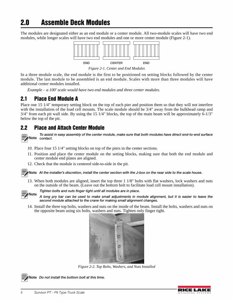
2.0 Assemble Deck ModulesThe modules are designated either as an end module or a center module. All two-module scales will have two endmodules, while longer scales will have two end modules and one or more center module (Figure 2-1).
Figure 2-1. Center and End Modules
In a three module scale, the end module is the first to be positioned on setting blocks followed by the centermodule. The last module to be assembled is an end module. Scales with more than three modules will haveadditional center modules installed.
Example – a 100' scale would have two end modules and three center modules.
2.1 Place End Module APlace one 15 1/4" temporary setting block on the top of each pier and position them so that they will not interferewith the installation of the load cell mounts. The scale module should be 3/4" away from the bulkhead ramp and3/4" from each pit wall side. By using the 15 1/4" blocks, the top of the main beam will be approximately 6-1/3"below the top of the pit.
2.2 Place and Attach Center ModuleTo assist in easy assembly of the center module, make sure that both modules have direct end-to-end surfacecontact.
10. Place four 15 1/4" setting blocks on top of the piers in the center sections. 11. Position and place the center module on the setting blocks, making sure that both the end module and
center module end plates are aligned. 12. Check that the module is centered side-to-side in the pit.
At the installer’s discretion, install the center section with the J-box on the near side to the scale house.
13. When both modules are aligned, insert the top three 1 1/8" bolts with flat washers, lock washers and nutson the outside of the beam. (Leave out the bottom bolt to facilitate load cell mount installation).
Tighten bolts and nuts finger tight until all modules are in place.
A long pry bar can be used to make small adjustments in module alignment, but it is easier to leave thesecond module attached to the crane for making small alignment changes.
14. Install the three top bolts, washers and nuts on the inside of the beam. Install the bolts, washers and nuts onthe opposite beam using six bolts, washers and nuts. Tighten only finger tight.
Figure 2-2. Top Bolts, Washers, and Nuts Installed
Do not install the bottom bolt at this time.
CENTEREND END
Note
Note
Note
Note
Assemble Deck Modules 5
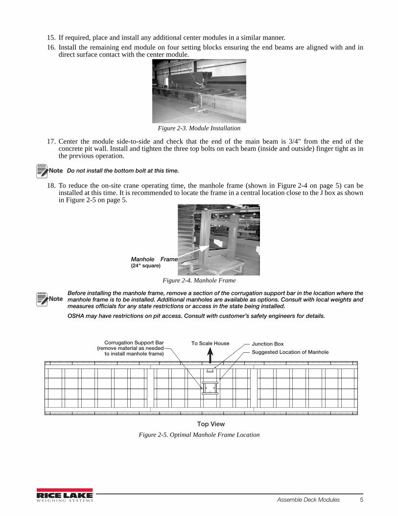
15. If required, place and install any additional center modules in a similar manner.16. Install the remaining end module on four setting blocks ensuring the end beams are aligned with and in
direct surface contact with the center module.
Figure 2-3. Module Installation
17. Center the module side-to-side and check that the end of the main beam is 3/4" from the end of theconcrete pit wall. Install and tighten the three top bolts on each beam (inside and outside) finger tight as inthe previous operation.
Do not install the bottom bolt at this time.
18. To reduce the on-site crane operating time, the manhole frame (shown in Figure 2-4 on page 5) can beinstalled at this time. It is recommended to locate the frame in a central location close to the J box as shownin Figure 2-5 on page 5.
Figure 2-4. Manhole Frame
Before installing the manhole frame, remove a section of the corrugation support bar in the location where themanhole frame is to be installed. Additional manholes are available as options. Consult with local weights andmeasures officials for any state restrictions or access in the state being installed.
OSHA may have restrictions on pit access. Consult with customer’s safety engineers for details.
Figure 2-5. Optimal Manhole Frame Location
Note
Manhole Frame(24" square)
Note
Top View
To Scale House
Suggested Location of Manhole
Junction BoxCorrugation Support Bar(remove material as needed
to install manhole frame)

6 Survivor PT - Pit Type Truck Scale
2.3 Install Outriggers and Deck Coping1. Install the outriggers on each module section using 3/4" x 2 1/2" bolts, washers and nuts at the locations
shown on the drawing. Torque all bolts to 260 ft-lb.
Figure 2-6. Outrigger Location
2. Position an L-shaped deck coping on top of the outriggers and secure it to the module frame with 1/2" x 2"bolts, nuts and washers.
3. Assemble the center section deck coping to the end channels using four 2 1/2" bolts, washers and nuts.4. Attach the third module deck coping to the center section and to the end of the module assembly.
To compensate for irregularities in pit dimensions, 1/2" shims are provided with the truck scale kit assembly.These shims are to be inserted (if required) between the coping attach points and the module frame assembly.
5. Repeat procedure for the opposite side. Recheck module assembly to see if it is centered side-to-side in thepit.
Figure 2-7. Optional Shim Placement
As an optional recommended procedure, and to make the module deck coping more rigid, each deck coping may betack welded to the outrigger at each contact location. It should be noted that during the concrete pour the deckcoping may bow outward towards the pit walls. To maintain a 3/4" gap between the deck coping and the side of thepit, it is recommended that temporary spacers (3/4" bolts or shim stock) be used
between the deck coping and the pit wall. Remove spacers after the concrete has set and before the scale is put intoservice.
Install the 3/4" bolts or shim stock and space at equal intervals between the deck coping and the pit wallcoping before welding.
2.4 Level Module AssemblyUsing a suitable jack and shims, raise each module section so that the top of the deck coping is level with the top ofthe pit. After raising module assembly, re-check module alignment to make sure that the top is level and centeredside-to-side in the pit.
Outrigger
Note
1/2" Shims InstalledHere if Required
Note
Load Cell Mount Installation 7
3.0 Load Cell Mount InstallationLoad cell mounts, complete with load cells and conduit adapters, have been assembled at the factory to save on-siteinstallation time. Load cell mount installation consists of sliding the complete unit into place beneath the deck,raising the mount with the leveling screws to the deck, and connecting the grounding strap.
When installing load cell mounts, start at one corner of the module assembly and install the remaining load cellmounts on that side. Likewise, when the load cell mounts are installed on the other side, start with the corner of themodule assembly.
The lower mounts assemblies come complete with load cells installed, so complete any necessary welding on thescale before installing mounts.
Remove load cell mount from packing box and file printed load cell Certification of Conformance (CC) in a safeplace for future reference.
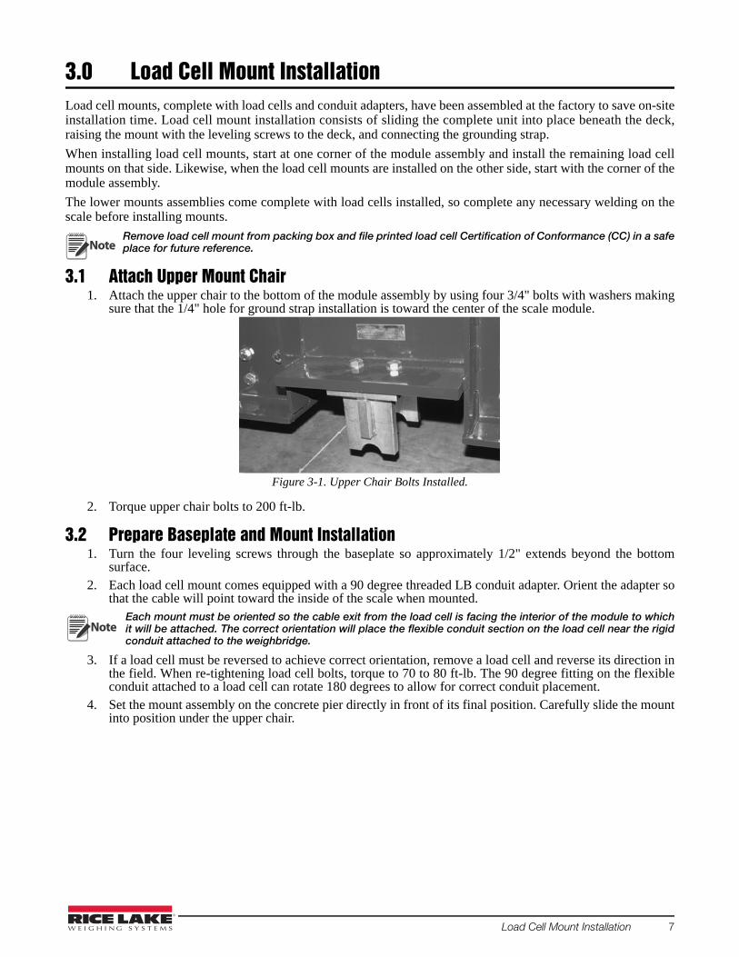
3.1 Attach Upper Mount Chair1. Attach the upper chair to the bottom of the module assembly by using four 3/4" bolts with washers making
sure that the 1/4" hole for ground strap installation is toward the center of the scale module.
Figure 3-1. Upper Chair Bolts Installed.
2. Torque upper chair bolts to 200 ft-lb.
3.2 Prepare Baseplate and Mount Installation1. Turn the four leveling screws through the baseplate so approximately 1/2" extends beyond the bottom
surface.2. Each load cell mount comes equipped with a 90 degree threaded LB conduit adapter. Orient the adapter so
that the cable will point toward the inside of the scale when mounted.Each mount must be oriented so the cable exit from the load cell is facing the interior of the module to whichit will be attached. The correct orientation will place the flexible conduit section on the load cell near the rigidconduit attached to the weighbridge.
3. If a load cell must be reversed to achieve correct orientation, remove a load cell and reverse its direction inthe field. When re-tightening load cell bolts, torque to 70 to 80 ft-lb. The 90 degree fitting on the flexibleconduit attached to a load cell can rotate 180 degrees to allow for correct conduit placement.
4. Set the mount assembly on the concrete pier directly in front of its final position. Carefully slide the mountinto position under the upper chair.
Note
Note

8 Survivor PT - Pit Type Truck Scale
3.3 Raise Mount into Final Position1. Turn the leveling screws to raise the mount until the link is centered in the chair bearing and lightly
touching. 2. Level the plate in both directions. When the baseplate is directly under the chair, the link will be hanging
vertical when centered in the chair, see Figure 3-2. Approximately 1/4" of the link should protrude beyondeach side of the chair, seeFigure 3-3.
Figure 3-2. Final Mount Position
3. If adjustment is necessary, tap baseplate edges lightly with a hammer to slide the entire mount sideways.
Figure 3-3. Load Cell Mount Parts
3.4 Attach Flexible Conduit SectionsA 30" section of flexible conduit (Figure 3-4) is included on each load cell.One end is threaded for mating with theLB connector at the load cell. The other end adapts to 3/4" galvanized rigid conduit.
Figure 3-4. Flexible conduit.
Flexible conduit may also be plastic-coated metal (flex conduit).
UPPER CHAIRLINK
1/4" PROTRUSION
LOAD CELL
LEVELING SCREW
BASEPLATE
1/2"
Note

Load Cell Mount Installation 9
3.4.1 Attach Grounding Strap1. Remove the 1/4-20 hex bolt with washer in the upper chair. Use this bolt to attach the braided grounding
strap to the upper chair as shown below.
Figure 3-5. Grounding Strap Location.
2. Attach lower end of grounding strap to either one of the two holes in the baseplate.
3.4.2 Install Lower Module Assembly BoltsUpon completing the load cell mount installation, the lower module assembly bolts can be installed at eachlocation. Torque all module assembly bolts to 200 ft-lb.
3.4.3 Install Anchor Bolts and Grout
Install Anchor BoltsEach mount requires two anchor bolts to prevent lateral motion. Two 7" x 3/4" anchor bolts with expansion headsare supplied with the scale for each load cell. The anchor bolts are installed in holes in each module pier.
1. Use an industrial hammer drill with a 3/4" carbide masonry bit at least 36" long to drill anchor bolt holes.This long bit allows the drill body to clear the side rail so the hole can be drilled nearly vertical. Hold thebit as close to vertical as possible and drill a 3/4" hole at least 6" into the concrete pier beneath each anchorbolt slot on both sides of the baseplate.
2. Place a washer and nut on each anchor bolt. Use a 24" long driver pipe with an inside diameter slightlylarger than the 3/4" bolt (shown in the illustration below) to drive anchors into the drilled holes until thewasher is solid against the baseplate.
Do not apply excessive force to the anchor bolt. Bending of the baseplate could occur.
Figure 3-6. Drive anchors into drilled holes.
Grounding StrapAttachment Point
Note
NOTE: Do not drive anchor boltwithout driver pipe.
10 Survivor PT - Pit Type Truck Scale
Grouting1. Erect temporary dams around each baseplate and inject 9000 psi non-shrinking, epoxy/cement grout.2. Take care not to leave air voids; the baseplate must have even support from continuous grout contact.
After the grout has hardened, tighten anchor bolt nuts until the heads expand and the bolts are solidlyanchored.
Figure 3-7. Grout example.
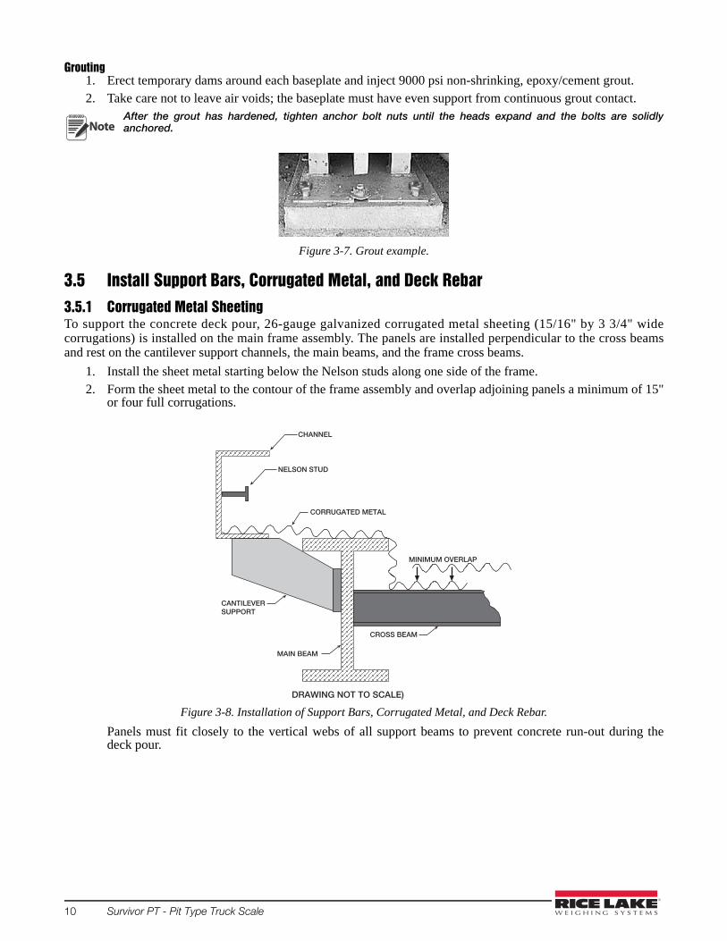
3.5 Install Support Bars, Corrugated Metal, and Deck Rebar3.5.1 Corrugated Metal SheetingTo support the concrete deck pour, 26-gauge galvanized corrugated metal sheeting (15/16" by 3 3/4" widecorrugations) is installed on the main frame assembly. The panels are installed perpendicular to the cross beamsand rest on the cantilever support channels, the main beams, and the frame cross beams.
1. Install the sheet metal starting below the Nelson studs along one side of the frame.2. Form the sheet metal to the contour of the frame assembly and overlap adjoining panels a minimum of 15"
or four full corrugations.
Figure 3-8. Installation of Support Bars, Corrugated Metal, and Deck Rebar.
Panels must fit closely to the vertical webs of all support beams to prevent concrete run-out during thedeck pour.
Note
CHANNEL
NELSON STUD
CANTILEVERSUPPORT
MAIN BEAM
CROSS BEAM
CORRUGATED METAL
MINIMUM OVERLAP
DRAWING NOT TO SCALE)

Load Cell Mount Installation 11
3. Trim sheet metal as needed for clearance around any vertical gussets in the support beams and around themanhole on the cross beams. Figure 3-9 shows the metal sheeting used on a EZ-SR truck scale installation.
Figure 3-9. Metal sheeting example.
Secure the corrugated metal sheet to the manhole frame by installing 12 sheet metal screws (or tack weld)around base of manhole frame.
When pouring concrete, make sure that concrete is poured over the overlap not into the overlap.
3.6 Deck RebarConcrete deck reinforcing consists of installing #5 rebar on 12" centers at the locations shown on the drawingalong with using standard construction practices.
At the installer’s discretion, rebar may or may not be tied together.
The first (bottom) layer of rebar installation consist of positioning 6'-3" rebars perpendicular to the main beams andon 1-1/2" chairs (bolsters) located on top of the corrugated sheet metal. On top of this rebar layer, a second layer(70' rebar) is installed perpendicular to the first layer and parallel to the main beam.
The third layer will be the 2' rebar placed on chairs. On top of these will be another layer of 70' rebar running thelength of the frame assembly.
The final two layers will require installing 9'-4' rebar on the appropriate chairs. On this will be the top layer of 70'rebar.
Note
Note

12 Survivor PT - Pit Type Truck Scale
4.0 Pour and Finish Concrete DeckWith a concrete crew of three experienced workers, a 70' by 10' scale can bepoured and finished in approximately three hours. Access to only one side ofthe scale is necessary as most concrete trucks carry extension chutes at least 16'long. If possible, order concrete in front-unloading trucks. The truck will bemoving slowly while filling; the improved driver-visibility with front-unloading makes that process faster and more accurate.
To protect against unsightly concrete splatters on the top of the supportchannels, mask off the top of the channel with tape or use 4 to 6 mil plastic tocover the top surface.
Position the unloading chute at the near left side of the scale and begin fillinghaving the truck move slowly to the right.
To ensure concrete flowing evenly into the frame and encasing all Nelson studs andrebar, a concrete vibrator is highly recommended. These units are available for rentat most construction equipment rental sources. They work very quickly to levelconcrete, settle out surface stones, and leave a stone-free layer at the top surface tomake finishing easier.
After vibrating to approximate level, screed the concrete to the level of the top ofthe support channels with a 2x4 board cut to length
With the deck level and floated, finish with either a magnesium float or steeltrowel for a neat deck line level with the top of the support beams and top of thepit.
When the entire frame has been floated with a magnesium float and has setenough for finishing, use a radius edger to finish the metal/concrete joint.
For a non-skid surface, use a stiff bristle broom for a brushed finish when theconcrete has set enough for final finishing. It is recommended that a non-skidsurface be applied for all northern tier states.

Pour and Finish Concrete Deck 13
Curing the Completed Concrete DeckThe concrete deck must be maintained in a moist state for at least seven days for a satisfactory cure. If the topsurface of the deck is allowed to dry during this time, the finished surface will be prone to unsightly spalling and beweakened from surface cracking.
A moist surface can be maintained by covering the entire deck with a continuous 4 to 6 mil sheet of polyethyleneplastic turned up and dammed at the ends and kept filled with 1" of water. Alternately, an epoxy-based concretecuring solution can be sprayed or rolled onto the deck surface immediately after final finishing and while theconcrete surface is still moist. As the epoxy curing solution will also seal in concrete stains on the exposed supportbeams, clean off stains with a damp sponge before applying the curing solution to the deck. Epoxy-based concretecuring products are available at contractor-supply companies. Do not use the petroleum-based or paraffin-basedwaterproofing agents specifically advertised for wood decks and concrete patios. These products are not curingagents, and will allow the deck surface to rapidly dry.
4.1 Optional EquipmentThe following is a brief summary of the optional Survivor SR-PT equipment available from RLWS.
Eighteen Inch Main Beam ModuleAn 18" main beam module is available from RLWS as an option. Use of this option will require increasing the pitpillar height approximately 6". Refer to the appropriate drawing for exact pit dimensions. This option should onlybe used in states where there is a requirement for a minimum of 48" clearance below the main I-beam flange. (Steelweight is increased approximately 1/3 when selecting this option.)

14 Survivor PT - Pit Type Truck Scale
5.0 Cable Installation
5.1 Load Cells to J-Box
Figure 5-1. J-Box Wiring and Conduit Runs for a Four Section/Three Module Scale
If using a single center module, some of the conduit runs are not used. These conduit runs are used whenmore than one center module is installed.
Load CellCable toConnector
Pocket 1 Conduit
Pocket 8 Conduit
Pockets 1, 2, 3, 4 Conduit runs to J-Box
Pocket 5 Conduit
Module A Module B
Pocket 3 Conduit
1
8
2
7
SI - GreenSI - WhiteEX - RedEX - Black
SHD - Shield
+-+-
+SI-SI
+EX-EX
SHD
+SI-SI
+EX-EX
SHD
+SI-SI
+EX-EX
SHD
+SI-SI
+EX-EX
SHD
J3
J4
J7
J8 J6
J5
J2
J1+SI-SI
+EX-EX
SHD
+SI-SI
+EX-EX
SHD
+SI-SI
+EX-EX
SHD
+SI-SI
+EX-EX
SHD
Load Cell #1 Load Cell #3
Load Cell #8 Load Cell #6
Load Cell #2 Load Cell #4
Load Cell #7 Load Cell #5
+SI-SI
+EX
-EX
SHD
-SEN
+SEN
SHD - Shield+SI-SI
+EX
-EX
SHD
-SEN
+SEN
Indicator/J10
Expansion/J9
Cable to IndicatorSI - Green+SI - White-
EX - Red+
EX - Black-SEN - Yellow-
SEN - Blue+
Pocket 4 Conduit
Pocket 6 Conduit
6
3
Pocket 4 Conduit
Pocket 5 Conduit
5
4
Module C
Note

Cable Installation 15
Figure 5-2. J-Box Wiring and Conduit Runs for a Five Section/Four Module Option
Each load cell is equipped with 60' of load cell cable, sufficient to reach a centrally-located junction box onstandard scales. A watertight conduit adapter and a 30" section of 3/4" flexible conduit is supplied for both ends ofeach load cell cable located at the load cell and at the junction box. Main conduit runs between these 30" flexibleend sections are 3/4" galvanized metal conduit already installed on the deck.
Pocket 1 Conduit
Pockets 1 and 2Conduit runs to J-Box
Pocket 3 Conduit
Pocket Conduit for J-Box 2cable to Expansion Slot in J-Box 1
Pocket 5 Conduit
Load CellCable toConnector
Pocket 9 and 10 Conduit runs to J-Box
SI - GreenSI - WhiteEX - RedEX - Black
SHD - Shield
+-+-
+SI-SI
+EX-EX
SHD
+SI-SI
+EX-EX
SHD
+SI-SI
+EX-EX
SHD
+SI-SI
+EX-EX
SHD
J3
J4
J7
J8 J6
J5
J2
J1+SI-SI
+EX-EX
SHD
+SI-SI
+EX-EX
SHD
+SI-SI
+EX-EX
SHD
+SI-SI
+EX-EX
SHD
Load Cell #1
Load Cell #2 Load Cell #9
Load Cell #3
Load Cell #10
Load Cell #8
+SI-SI
+EX
-EX
SHD
-SEN
+SEN
SHD - Shield
+SI-SI
+EX
-EX
SHD
-SEN
+SEN
Indicator/J10
Expansion/J9
Cable from J-Box 2SI - Green+SI - White-
EX - Red+
EX - Black-SEN - Yellow-
SEN - Blue+
Pocket 10 Conduit
Module C Module B Module AModule D
Pocket 4 Conduit
3
8
21
10 9
54
Section 1B
Section 1A
Section 2B
Section 2A
Section 3B
Section 3A
Section 4B
Section 4A
Section 5B
Section 5A
67
Pocket 5 and 6 Conduit J-Box 2J-Box 1
Load CellCable toConnector
SI - GreenSI - WhiteEX - RedEX - Black
SHD - Shield
+-+-
+SI-SI
+EX-EX
SHD
+SI-SI
+EX-EX
SHD
J3
J4 J2
J1+SI-SI
+EX-EX
SHD
+SI-SI
+EX-EX
SHD
Load Cell #4 Load Cell #7
Load Cell #5 Load Cell #6
+SI-SI
+EX
-EX
SHD
-SEN
+SEN
SHD - Shield+SI-SI
+EX
-EX
SHD
-SEN
+SEN
Indicator/J10
Expansion/J9
Cable to J-Box 1SI - Green+SI - White-
EX - Red+
EX - Black-SEN - Yellow-
SEN - Blue+
Detail A Detail B
SHD - Shield
Cable to IndicatorSI - Green+SI - White-
EX - Red+
EX - Black-SEN - Yellow-
SEN - Blue+
J-Box 1 - Detail A
J-Box 2 - Detail B

16 Survivor PT - Pit Type Truck Scale
5.2 Junction Box to IndicatorA 60' section of 6-wire home run cable is supplied. It is to be run in 3/4" galvanized metal conduit from thejunction box to the indicator. A 30" flexible conduit section and watertight conduit connector is provided wherethis cable exits the junction box. Galvanized metal conduit must be obtained locally.
Scales over 70 feet in length have two or three j-boxes. Refer to Engineering Drawings provided with scale fordetails.
5.3 Indicator to PeripheralsAll 3/4" metal conduit for cabling from the indicator to remote displays and other peripheral devices must beobtained locally. Conduit runs may be buried in a trench or secured above ground. Use separate conduit runs forAC power and DC data lines to avoid interference. As a general guideline, run AC and DC cables in separatetrenches if possible. When DC data cables must run in the same trench as AC power lines, separate cables as muchas possible.
5.4 Single-Point Ground ConductorA bare 10-gauge solid wire is run from the scale frame to the grounding lug on the junction box, then undergroundto the main AC power earth ground. If the optional DC transient protection board is installed, the ground conductorshould also be connected to the transient protection board’s ground lug. Consult with the local power utility forrestrictions or requirements for utility ground rod connections.
5.5 J-Box ConnectionsEach JB8SPT j-box is large enough to hold the summingboard, transient protection devices, desiccant package, andextra load cell cable coiled inside the enclosure.
In a single-platform scale, the single j-box location isdetermined by the length of the load cell cables and the fourmounting studs on the outside main beams. Both A and Bmodules are equipped with mounting studs. In a multi-axlescale with independent sections, each section requires its ownjunction box to sum the load cell signals from that section.
A summing card mounted within the junction box is used tomake all cable terminal connections. All terminal pinfunctions are clearly marked.
A 10-gauge bare ground wire is run from one of the junctionbox mounting studs to the ground lug of the junction box asshown in the figure below. The ground lug on the bottom ofthe junction box is connected to a buried ground cable fromthe AC power ground terminal or ground rod, thus groundingthe scale frame to the same single-point ground point as theAC power for the indicator.
Before final closure, add an industrial corrosion inhibitor anddesiccant (RLWS Industrial Corrosion Inhibitor, PN 16037)to the junction box enclosure. This desiccant protects an enclosure up to 5 ft3 from internal corrosion forapproximately 1 year.
Make sure that the 10 gauge ground wire makes connection to bare metal.
Note
Ground Lug(located next to J-box)
R41
JP17
JP7
R52
R50
R40
R24
R14
R15
JP20
JP10
R26
R51
R49
R47
JP16
R45
R43
JP9
R23
R21
JP6
JP8
R17
R38
R36
R34
JP11
R32
R30
R28
R10
R8
JP1
R4
R2
JP12
JP2
VR9
JP19R48
VR7
JP18
R42
R44
R22
R25
R16
R18
VR2
R19
R39
VR10
R35
R37
VR11
R27
R29
R31
R9
R11
R12
R1
R3
R5
VR5
R6
JP5
JMP/NEGJMP/POS
VR8
VR3
VR1
VR12
VR6
J1
VR4
J2 R13
R7
EXPANSION/J9
J5
ARC
R46
JP4
JP3
ARGND
JP14
JP15
JP13
L3
L4
L2
J8
J4
J3
J6
L1R20
J7
INDICATOR/J10
JP
TRIM
TRIM
TO
-EX
+EX
+SI
-EX
+EX
+SI
-EX
+EX
1
+SI
-EX
+EX
+SI
JP
JP
TO
SIG
NA
L
2005
SIG
NA
L
CUT
TO
DIS
ABL
E
CUT
CELL
#CE
LL#
CELL
#
SHD
1
SHD
-SI
1
-SI
SHD
-SI
1
-SI
SHD
SIG
NA
L
CUT
TOCU
T
SECT
#
DIS
ABL
E
CELL
#CE
LL#
SIG
NA
LSI
GN
AL
SIG
NA
L
DLD
DIS
ABL
E
CELL
#
SECT
#
DIS
ABL
E
CELL
#
RICE
LA
KE W
EIG
HIN
G S
YSTE
MS
JP
-EX
+EX
+SI
-EX
+EX
+SI
-EX
+EX
+SI
-EX
+EX
+SI
SIG
NA
L
TRIM
TRIM
TRIM
TRIM
TRIM
TRIM
Assembly
-EX
-EX
+EX
+SI
SHD
1
SHD
-SI
1
-SI
1
-SI
SHD
1
-SI
SHD
CONNECT BOTH SHUNTS
TO APPLY SIGNAL
SECT
#
SIG
NA
LSI
GN
AL
SIG
NA
L
CELL
#
PN Rev.
+SI
-SI
-SI
SECT
#
+SEN
SHD
+SEN
SHD
DISCONNECT BOTH SHUNTS
TO REMOVE SIGNAL
+EX
-SEN
-SEN
CUT TRACE TO ISOLATE SENSE LINE
Transient Board Connectors
Grounding Lug
10 ga. bare ground wireto DC protection ground
connection before indicator
Figure 5-3. J-Box Grounding.
Note
Cable Installation 17
5.6 Electrical Ground ConnectionsImproper grounding systems on outdoor truck scales often cause corrupted data as a result from ground-loopcurrent flows. Improper grounding systems may also invite possible lightning strikes and cause damage tocostly electronic systems. Always attempt to establish a single-point grounding system.
When establishing a ground system for the scale installation, do not install more than one ground rod for each scalelocation. Separate earth grounds do not share the same zero reference as the existing earth ground for the AC powersystem. The difference in electrical potential invites ground-loop current flow between the separate grounds, oftencorrupting serial data, such as RS-232, which depends on a stable zero reference.
In addition, a separate earth ground system at the scale can actually invite lightning or power surge damage:
• A minor power line surge in the scale house electrical supply should immediately be shunted to ground. If aseparate ground system exists at the scale with a lower potential than the main ground, the surge may travel tothe scale ground rod, damaging load cells on its way.
• A lightning ground strike may instantly raise the zero potential of a ground rod at the scale location whileleaving the scale house ground rod unaffected. A lightning surge takes the easiest path to the lower-potentialground: through the scale wiring and back to the scale house ground, therefore possibly damaging the indicatoron its way.
The best grounding system for the scale is the same grounding system used for the incoming AC power system.The 120 VAC power source used to power the indicator is connected to an existing earth ground rod system at thescale house or other building where the indicator is located. This consist of a double ground rod system of two 5/8"x 8' copper rods driven 8' deep at the service entrance where the local utility company brings their lines into thebuilding. The local utility company can test the resistance of the existing ground rods with a clamp-on megohmeterto measure resistance. A reading of 3 3/4" or less is acceptable as a ground. If the test determines that the groundingsystem is inadequate, the utility company can suggest methods to improve the system. It is crucial that the scaleowner authorize and make the recommended improvements to assure an adequate electrical ground. Do notconnect the scale to the AC power supply until the grounding system is adequate.
Each load cell grounding strap is securely fastened to the top and bottom plates of each load cell mount. Thegrounding strap is designed to channel power surges on the deck around—rather than through—the load cell toground. All ground connections must be properly torqued and rechecked at regular service intervals. Afterconnecting to bare metal apply a thick coating of anti-oxidant grease on all ground connections to preventcorrosion.
A separate grounding system conductor must extend uninterrupted from the main service panel ground to the scaleto protect load cells and scale wiring from lightning and other transient damage. As a minimum requirement forground wire installation, the conductor must be at least a 10-gauge unsheathed copper wire. Run the bare groundwire conductor intact from the AC power ground rod to the scale in a separate trench. Bring the wire up from thetrench near the junction box and attach it to the ground lug of the junction box. Use a short piece of 10-gauge wireto ground the scale frame by running a ground wire from the junction box ground lug to a junction box mountingbolt on the scale frame.
5.7 Install Transient ProtectionAn five-year lightning protection package comes standard on all SURVIVOR® 920i truck scales. This package isdesigned to protect the AC and DC portions of the system. The package includes:
• A DC transient protection board mounted within the junction box. This DC transient protector canaccommodate up to eight load cells and will help protect serial communication lines. Scales with more thaneight load cells require a DC transient protection board in each junction box.
• A self-contained DC transient protection unit in the homerun cable at the indicator.• A 10-gauge bare ground conductor cable. This conductor cable, to be buried underground, runs from the scale
frame to the junction box DC transient board, to the indicator DC transient board, and finally to the AC powerground lug.
• A 120 VAC uninterruptable power supply/surge protector in the AC line before the indicator.
Transient protection for additional peripheral devices (except some boards) is not included in the standardtransient protection package. Call the Rice Lake Weighing Systems Sales Department at (715) 234-9171 foradditional transient protection for these devices.
Note

18 Survivor PT - Pit Type Truck Scale
Figure 5-4. Single-Point Grounding Diagram.
AC PowerSupply
#10 CopperGround Wire
SerialCommunication
HomerunCable
Load CellCable
UJB-3T6DC Transient Protection
RLWS PN 21134
TP-232DC Transient Protection
RLWS PN 33185
TP-232DC Transient Protection
RLWS PN 33185
AC Outlet
Leviton U0425-AKPAC Transient Protection
RLWS PN 99224
AC Outlet
Power Company Ground Rod*Always verify that installed wiring is properly grounded
JB8SPTJunction Box
With Transient ProtectionRLWS PN 91783
R41
JP17
JP7
R52
R50
R40
R24
R14
R15
JP20
JP10
R26
R51
R49
R47
JP16
R45
R43
JP9
R23
R21
JP6
JP8
R17
R38
R36
R34
JP11
R32
R30
R28
R10
R8
JP1
R4
R2
R33
JP12
JP2
VR9
JP19R48
VR7
JP18
R42
R44
R22
R25
R16
R18
VR2
R19
R39
VR10
R35
R37
VR11
R27
R29
R31
R9
R11
R12
R1
R3
R5
VR5
R6
JP5
JMP/NEGJMP/POS
VR8
VR3
VR1
VR12
VR6
J1
VR4
J2 R13
R7
EXPANSION/J9
J5
ARC
R46
JP4
JP3
ARGND
JP14
JP15
JP13
L3
L4
L2
J8
J4
J3
J6
L1R20
J7
INDICATOR/J10
JP
TRIM
TRIM
TO
-EX
+EX
+SI
-EX
+EX
+SI
-EX
+EX
1
+SI
-EX
+EX
+SI
JP
JP
TO
SIG
NA
L
2005
SIG
NA
L
CUT
TO
DIS
ABL
E
CUT
CELL
#CE
LL#
CELL
#
SHD
1
SHD
-SI
1
-SI
SHD
-SI
1
-SI
SHD
SIG
NA
L
CUT
TOCU
T
SECT
#
DIS
ABL
E
CELL
#CE
LL#
SIG
NA
LSI
GN
AL
SIG
NA
L
DLD
DIS
ABL
E
CELL
#
SECT
#
DIS
ABL
E
CELL
#
RICE
LA
KE W
EIG
HIN
G S
YSTE
MS
JP
-EX
+EX
+SI
-EX
+EX
+SI
-EX
+EX
+SI
-EX
+EX
+SI
SIG
NA
L
TRIM
TRIM
TRIM
TRIM
TRIM
TRIM
Assembly
-EX
-EX
+EX
+SI
SHD
1
SHD
-SI
1
-SI
1
-SI
SHD
1
-SI
SHD
CONNECT BOTH SHUNTS
TO APPLY SIGNAL
SECT
#
SIG
NA
LSI
GN
AL
SIG
NA
L
CELL
#
PN Rev.
+SI
-SI
-SI
SECT
#
+SEN
SHD
+SEN
SHD
DISCONNECT BOTH SHUNTS
TO REMOVE SIGNAL
+EX
-SEN
-SEN
CUT TRACE TO ISOLATE SENSE LINE
Transient Board Connectors
Grounding Lug
Leviton U0425-AKPAC Transient Protection
RLWS PN 99224

Trimming and Calibration 19
6.0 Trimming and Calibration
6.1 Overview and Equipment RequiredLoad Cell TrimmingIndividual load cell signal trimming (equalizing the signal output from each load cell) must be done first alongeach side of the scale so all cells on a side have equal signal output. Adjustments are somewhat interactive, so eachside should be done at least twice.
Once that is done, load cell pairs—one from each side—are trimmed as paired sections until each sectional outputis equal. Adjustments to each section should also be done at least twice.
Figure 6-1. Load Cell Trimming Diagram
Equipment RequiredBoth of these trimming operations can be done using only a weight cart parked in various locations on the scale.Final verification of equal output trimming, however, will require test weights to be placed on the deck in variouslocations.
6.2 Trimming Individual Cells1. Connect all load cells to the summing board terminals in the junction box.2. Connect the main interface cable from the junction box to the indicator. 3. Power up the indicator. 4. Turn all load cell potentiometers (individual and section) in the junction box clockwise until a clicking
noise is heard when you continue turning. This eliminates any initial resistance so all signals are at fullstrength. You’re now ready to do individual signal trimming.
Side 1The first objective is to adjust individual load cells along one side of the scale for equal signal output when equalweight is put on those cells. For convenience, that side of the scale will be referred to as Side 1. The trimmingweight you will use will be the loaded weight cart.
1. Park the cart as close as possible to Side 1 being trimmed with the wheels centered over the end load cellmount (No. 1 in drawing to below). Record the indicator reading. Remember that the scale is stilluncalibrated, so the indicator readings are simply raw counts rather than weight units.
1st – Trim Side 1 Cells(1, 2, 3, 4)
2nd – Trim Side 2 Cells(5, 6, 7, 8)
3rd – Trim Sections(1, 8; 2, 7; 3, 6; 4, 5)
WeightCart
1 432
8 567
Load Cell numbersas viewed fromDigital Indicator

20 Survivor PT - Pit Type Truck Scale
Figure 6-2. Trimming Load Cell Number One
2. Move the cart directly over mount No. 2 and record that reading. Move the cart directly over mount No. 3and record that reading. Move the cart so the wheels are centered directly over mount No. 4 (you may haveto turn the weight cart around so all wheels remain on the scale) and record the reading.
Figure 6-3. Trimming Load Cell Numbers Two, Three, and Four
3. The lowest reading of the four will be your reference cell. You won’t change that cell’s signal. Insteadyou’ll use the individual cell potentiometers for the other three cells to reduce those signals to match yourreference cell. Remember that you turned all pots to full signal (0 resistance) before starting. So you can’tincrease the signal from any cell—you can only decrease signal by trimming with the pots.
4. Note that the best trim is always the least trim. If one of the four readings differs from the others by morethan 5% of the displayed counts, there is probably a mechanical problem with that load cell mount causingthe large difference. Find it and correct it before going on. Check for binding, an out-of-level or misalignedlink, or similar problems with the load cell and mount. Do not try to trim down large signal differenceswith resistance pots—you’ll only add larger problems for yourself later because of interaction betweenmounts.
5. Park the loaded weight cart over one of the high-reading cells on Side 1. Turn that cell’s individualpotentiometer until the displayed reading equals your recorded reference cell reading. Repeat for the othertwo high-reading cells on side 1.
6. As adjustments are somewhat interactive, repeat the process in Steps 1 through 5 until all four cells on Side1 read within 1% of each other.
7. Side 2. Move to the Side 2 of the scale. Load each cell in turn with the weight cart and record readings onthose four cells in the same way. The cell which reads the closest to the Side 1 reference cell will be used asyour reference cell for trimming the other cells on side 2.
Figure 6-4. Trimming Load Cell Number Five.
The reference cell on Side 2 should be the same as the Side 1 readings. Move the weight cart over the cellchosen for the Side 2 reference cell. Adjust the cell’s individual pot to equal the final Side 1 readings. In theexample at left, Cell 8 has been chosen as the Side 2 reference cell.
8. Reload the other Side 2 cells (5, 6, 7 in the example) in turn with the weight cart and adjust their individualpots so their readings are equal to the Side 2 reference cell (8 in the example).
1 432
8 567
1 432
8 567
1 432
8 567
Note

Trimming and Calibration 21
Figure 6-5. Trimming Load Cell Number Eight.
9. Repeat Steps 7 through 9 if needed to get all Side 2 cells reading within 1% of each other and within 1% ofthe Side 1 reference cell.
6.3 Trimming Paired SectionsNow that you’ve trimmed all individual load cells for equal output, pairs of load cells on opposite sides of the scalemust be trimmed for equal sectional output. This process is called section signal trimming.
1. Park the loaded weight cart in the middle of the scale and directly over an imaginary line connecting anend pair of cells (1 and 8 in the example at right). Record the indicator reading.
Figure 6-6. Trimming Paired Section 1:8.
2. Move the weight cart directly over the next paired cell section (2, 7 in Figure 6-7) and record the indicatorreading.
Figure 6-7. Trimming Paired Sections 2:7, 3:6, and 4:5.
Do the same for the last two paired sections (cells 3, 6 and 4, 5).3. Choose the lowest reading of the four as your reference section, which will not be adjusted. Using the
section potentiometers, reload the other three sections in turn and trim the sections to match the reading ofthe reference section. Recheck section readings a second time as the adjustment made may be somewhatinteractive.
4. As a final verification of the load cell trimming, do a final corner check. Place a 1000 lb. weight on onecorner of the platform and record the raw-count reading on the indicator. Move the weight to all the othercorners in turn and record those readings. The readings should be within 1% of each other.
1 432
8 567
1 432
8 567
1 432
8 567
22 Survivor PT - Pit Type Truck Scale
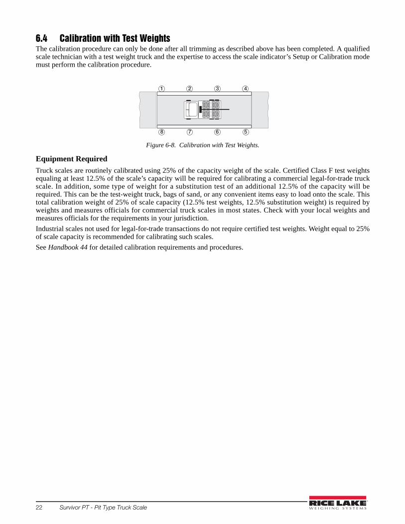
6.4 Calibration with Test WeightsThe calibration procedure can only be done after all trimming as described above has been completed. A qualifiedscale technician with a test weight truck and the expertise to access the scale indicator’s Setup or Calibration modemust perform the calibration procedure.
Figure 6-8. Calibration with Test Weights.
Equipment Required
Truck scales are routinely calibrated using 25% of the capacity weight of the scale. Certified Class F test weightsequaling at least 12.5% of the scale’s capacity will be required for calibrating a commercial legal-for-trade truckscale. In addition, some type of weight for a substitution test of an additional 12.5% of the capacity will berequired. This can be the test-weight truck, bags of sand, or any convenient items easy to load onto the scale. Thistotal calibration weight of 25% of scale capacity (12.5% test weights, 12.5% substitution weight) is required byweights and measures officials for commercial truck scales in most states. Check with your local weights andmeasures officials for the requirements in your jurisdiction.
Industrial scales not used for legal-for-trade transactions do not require certified test weights. Weight equal to 25%of scale capacity is recommended for calibrating such scales.
See Handbook 44 for detailed calibration requirements and procedures.
1 432
8 567
Load Cell Replacement 23
7.0 Load Cell ReplacementLoad cell replacement procedures are included in the following paragraphs.
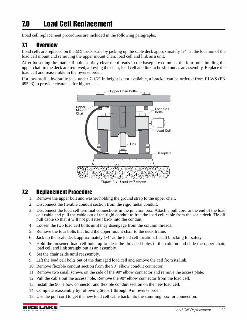
7.1 OverviewLoad cells are replaced on the 920i truck scale by jacking up the scale deck approximately 1/4" at the location of theload cell mount and removing the upper mount chair, load cell and link as a unit.
After loosening the load cell bolts so they clear the threads in the baseplate columns, the four bolts holding theupper chair to the deck are removed, allowing the chair, load cell and link to be slid out as an assembly. Replace theload cell and reassemble in the reverse order.
If a low-profile hydraulic jack under 7-1/2" in height is not available, a bracket can be ordered from RLWS (PN49523) to provide clearance for higher jacks.
Figure 7-1. Load cell mount.
7.2 Replacement Procedure1. Remove the upper bolt and washer holding the ground strap to the upper chair.2. Disconnect the flexible conduit section from the rigid metal conduit.3. Disconnect the load cell terminal connections in the junction box. Attach a pull cord to the end of the load
cell cable and pull the cable out of the rigid conduit to free the load cell cable from the scale deck. Tie offpull cable so that it will not pull itself back into the conduit.
4. Loosen the two load cell bolts until they disengage from the column threads.5. Remove the four bolts that hold the upper mount chair to the deck frame. 6. Jack up the scale deck approximately 1/4" at the load cell location. Install blocking for safety.7. Hold the loosened load cell bolts up to clear the threaded holes in the column and slide the upper chair,
load cell and link straight out as an assembly.8. Set the chair aside until reassembly.9. Lift the load cell bolts out of the damaged load cell and remove the cell from its link.10. Remove flexible conduit section from the 90° elbow conduit connector. 11. Remove two small screws on the side of the 90° elbow connector and remove the access plate.12. Pull the cable out the access hole. Remove the 90° elbow connector from the load cell.13. Install the 90° elbow connector and flexible conduit section on the new load cell.14. Complete reassembly by following Steps 1 through 9 in reverse order.15. Use the pull cord to get the new load cell cable back into the summing box for connection.
Upper Chair Bolts
Load CellBolts
Baseplate
Link
Load Cell
UpperMountChair

24 Survivor PT - Pit Type Truck Scale
Vehicle Scale Limited WarrantyRice Lake Weighing Systems (RLWS) warrants that all RLWS brand equipment and systems properly installed bya Distributor will operate in accordance with written specifications as confirmed by the Distributor and accepted byRLWS. All systems and components are warranted against defects in materials and workmanship for 5 years fromdate of shipment from the manufacturer. Furthermore, the seller warrants the fabricated weighbridge against faultyworkmanship and defective materials for 10 years from the date of shipment from the manufacturer.
RLWS warrants that the equipment sold hereunder will conform to the current written specifications authorized byRLWS. RLWS warrants the equipment against faulty workmanship and defective materials. If any equipment failsto conform to these warranties, RLWS will, at its option, repair or replace such goods returned within the warrantyperiod subject to the following:
• Upon discovery by Buyer of such non-conformity, RLWS will be given prompt written notice with adetailed explanation of the alleged deficiencies.
• Individual electronic components returned to RLWS for warranty purposes must be packaged to preventelectrostatic discharge (ESD) damage in shipment. Packaging requirements are listed in a publication,“Protecting Your Components From Static Damage in Shipment,” available from RLWS EquipmentReturn Department.
• Examination of such equipment by RLWS confirms that the non-conformity actually exists, and was notcaused by accident, misuse, neglect, alteration, improper installation, improper repair, or improper testing.RLWS shall be the sole judge of all alleged non-conformities.
• Such equipment has not been modified, altered or changed by any person other than RLWS or its dulyauthorized repair agents.
• RLWS will have a reasonable time to repair or replace the defective equipment. Buyer is responsible forshipping charges both ways.
• Vehicle scale procts are eligible for warranty labor and mileage charges with pre-approval by RLWSService Department, and only to the limits described in the vehicle scale reimbursement program.
• RLWS will not be liable for the cost of any repairs made by others.THESE WARRANTIES EXCLUDE ALL OTHER WARRANTIES, EXPRESSED OR IMPLIED, INCLUDING WITHOUTLIMITATION WARRANTIES OF MERCHANTABILITY OR FITNESS FOR A PARTICULAR PURPOSE. NEITHER RLWSNOR DISTRIBUTOR WILL BE LIABLE FOR INCIDENTAL OR CONSEQUENTIAL DAMAGES. RLWS AND BUYER AGREE THAT RLWS’ SOLE AND EXCLUSIVE LIABILITY HEREUNDER IS LIMITED TO REPAIROR REPLACEMENT OF SUCH GOODS. IN ACCEPTING THIS WARRANTY, THE BUYER WAIVES ALL OTHER CLAIMSTO WARRANTY.SHOULD THE SELLER BE OTHER THAN RLWS, THE BUYER AGREES TO LOOK ONLY TO THE SELLER FORWARRANTY CLAIMS.No terms, conditions, understanding, or agreements purporting to modify the terms of this warranty shall have anylegal effect unless made in writing and signed by a corporate officer of RLWS and the Buyer.
© Rice Lake Weighing Systems, Inc. Rice Lake, WI USA. All Rights Reserved.
RICE LAKE WEIGHING SYSTEMS • 230 WEST COLEMAN STREET • RICE LAKE, WISCONSIN 54868 • USA


230 W. Coleman St. • Rice Lake, WI 54868 • USAU.S. 800-472-6703 • Canada/Mexico 800-321-6703 • International 715-234-9171 • Europe +31 (0)26 472 1319
www.ricelake.com www.ricelake.mx www.ricelake.eu www.ricelake.co.in m.ricelake.com
Rice Lake Weighing Systems is an ISO 9001 registered company. © Rice Lake Weighing Systems Specifications subject to change without notice.
© Rice Lake Weighing systems 07/16/2015 PN 53280 Rev D