m-bus protocol m-bus protocol – technical description page 4 1 m-bus module description of m-bus...
TRANSCRIPT
M-Bus Protocol – Technical description
Page 1
M-Bus Protocol For electronic meters
Technical description
Version 2.1

M-Bus Protocol – Technical description
Page 2
Table of Contents
1 M-Bus module ___________________________________________________________________ 4
1.1 M-Bus module _______________________________________________________________________ 4
1.2 General data ________________________________________________________________________ 4
1.3 Read-out data that can be parameterized _________________________________________________ 5
1.4 Read-out data parameterization ________________________________________________________ 7 1.4.1 Structure of Parameter Set for Read-out Data possible _____________________________________________ 7 1.4.2 Default Parameter Set _____________________________________________________________________ 10
2 Telegrams for Parameterization and Read-out Data of M-Bus module _____________________ 11
2.1 Primary Address (A-Field) ___________________________________________________________ 11 2.1.1 Structure of Primary Address (A-Field) ________________________________________________________ 11
2.2 Secondary Address (UD) _____________________________________________________________ 11 2.2.1 Structure of Secondary Address (UD) _________________________________________________________ 11 2.2.2 Wildcard ________________________________________________________________________________ 12
2.3 Reset M-Bus module access counter (SND_UD) __________________________________________ 12 2.3.1 Reset M-Bus module access counter using Primary Address _______________________________________ 12 2.3.2 Reset M-Bus module access counter using Secondary Address______________________________________ 13
2.4 Set baud rate (SND_UD) _____________________________________________________________ 14 2.4.1 Set baud rate using Primary Address __________________________________________________________ 14 2.4.2 Set baud rate using Secondary Address ________________________________________________________ 14
2.5 Set Parameter Set to Default Read-out Data (SND_UD)____________________________________ 15 2.5.1 Set Parameter Set to all Read-out Data possible using Primary Address ______________________________ 15 2.5.2 Set Parameter Set to all Read-out Data possible using Secondary Address ____________________________ 15
2.6 Set Parameter Set to any Read-out Data desired (SND_UD) ________________________________ 16 2.6.1 Set Parameter Set for any Read-out Data desired using Primary Address _____________________________ 16 2.6.2 Set Parameter Set for any Read-out Data desired using Secondary Address____________________________ 17
2.7 Set Primary Address (SND_UD) _______________________________________________________ 18 2.7.1 Set Primary Address using Primary Address ____________________________________________________ 18 2.7.2 Set Primary Address using Secondary Address __________________________________________________ 18
2.8 Set Secondary Address (SND_UD) _____________________________________________________ 19 2.8.1 Set Secondary Address using Primary Address __________________________________________________ 19 2.8.2 Set Secondary Address using Secondary Address ________________________________________________ 20
2.9 Set Secondary Address and Manufacturer’s Mark (SND_UD) ______________________________ 21 2.9.1 Set Secondary Address and Manufacturer’s Mark using Primary Address_____________________________ 21 2.9.2 Set Secondary Address and Manufacturer’s Mark using Secondary Address ___________________________ 22
2.10 Reset Active Energy Tariff 1 + 2 and Reactive Energy Tariff 1 + 2 (SND_UD) _________________ 23 2.10.1 Reset Active and Reactive Energy using Primary Address _______________________________________ 23 2.10.2 Reset Active and Reactive Energy using Secondary Address _____________________________________ 24
2.11 Select M-Bus Module using Secondary Address (SND_UD) ________________________________ 25 2.11.1 Select M-Bus Module using Secondary Address _______________________________________________ 25
2.12 Transmit Read-out Data (REQ_UD2) __________________________________________________ 26 2.12.1 Transmit Read-out Data__________________________________________________________________ 26 2.12.2 Telegram of Read-out Data by M-Bus module (RSP_UD) _______________________________________ 27 2.12.3 Structure of Telegram for Read-out Data possible _____________________________________________ 28
2.12.3.1 Parameterset Identification ___________________________________________________________ 28

M-Bus Protocol – Technical description
Page 3
2.12.3.2 Active Energy Import Total __________________________________________________________ 28 2.12.3.3 Reactive Energy Import Total _________________________________________________________ 29 2.12.3.4 Active Energy Import Phase L1, L2 and L3 Tariff 1 _______________________________________ 29 2.12.3.5 Active Energy Import Total Tariff 1 ____________________________________________________ 29 2.12.3.6 Active Energy Import Phase L1 , L2 and L3 Tariff 2_______________________________________ 30 2.12.3.7 Active Energy Import Total Tariff 2 ____________________________________________________ 30 2.12.3.8 Active Energy Export Phase L1, L2 and L3 Tariff 1 _______________________________________ 30 2.12.3.9 Active Energy Export Total Tariff 1 ____________________________________________________ 30 2.12.3.10 Active Energy Export Phase L1, L2 and L3 Tariff 2 _______________________________________ 31 2.12.3.11 Active Energy Export Total Tariff 2 ____________________________________________________ 31 2.12.3.12 Reactive Energy Import Phase L1, L2 and L3 Tariff 1 _____________________________________ 31 2.12.3.13 Reactive Energy Import Total Tariff 1 __________________________________________________ 32 2.12.3.14 Reactive Energy Import Phase L1, L2 and L3 Tariff 2 _____________________________________ 32 2.12.3.15 Reactive Energy Import Total Tariff 2 __________________________________________________ 32 2.12.3.16 Reactive Energy Export Phase L1, L2 and L3 Tariff 1 _____________________________________ 33 2.12.3.17 Reactive Energy Export Total Tariff 1 __________________________________________________ 33 2.12.3.18 Reactive Energy Export Phase L1, L2 and L3 Tariff 2 _____________________________________ 33 2.12.3.19 Reactive Energy Export Total Tariff 2 __________________________________________________ 34 2.12.3.20 Active Power Phase L1, L2 and L3_____________________________________________________ 34 2.12.3.21 Active Power Total _________________________________________________________________ 34 2.12.3.22 Reactive Power Phase L1, L2 and L3 ___________________________________________________ 34 2.12.3.23 Reactive Power Total _______________________________________________________________ 35 2.12.3.24 Apparent Power Phase L1, L2 and L3 __________________________________________________ 35 2.12.3.25 Apparent Power Total _______________________________________________________________ 35 2.12.3.26 Voltage Phase L1, L2 and L3 _________________________________________________________ 36 2.12.3.27 Voltage Total single Phase Meter ______________________________________________________ 36 2.12.3.28 Current Phase L1, L2 and L3 _________________________________________________________ 36 2.12.3.29 Current Total ______________________________________________________________________ 37 2.12.3.30 Power factor cos phi Phase L1, L2 and L3 _______________________________________________ 37 2.12.3.31 Power factor cos phi Total ___________________________________________________________ 37 2.12.3.32 Netfrequency ______________________________________________________________________ 37 2.12.3.33 Staus Byte 4 (Range Overflow) ________________________________________________________ 38 2.12.3.34 Tariff presently operating ____________________________________________________________ 38
2.13 Telegram of Error Flags (REQ_UD1) __________________________________________________ 39 2.13.1 Transmit Error Flags of M-Bus module _____________________________________________________ 39 2.13.2 Telegram of Error Flags (RSP_UD) ________________________________________________________ 39 2.13.3 Structure of Error Flags Data Transmission from Meter to M-Bus module __________________________ 40 2.13.4 Structure of Error Flags M-Bus module _____________________________________________________ 41
2.14 Initialisation of M-Bus module (SND_UD2) ______________________________________________ 42 2.14.1 Initialisation of M-Bus module ____________________________________________________________ 42

M-Bus Protocol – Technical description
Page 4
1 M-Bus module
Description of M-Bus module and different variants of the model. The alternating current single and three-phase static meter can be provided with an M-Bus communication module. The M-Bus communication module (inside of a special DIN single-module housing) is mounted next to the meter. Make sure that the IR modules of the meter and communication module face each other.
1.1 M-Bus module
- M-Bus module conforming to EN1434
- Wired by YCYM or J.Y(St)Y 2 x 2 x 0.8 mm strand double-pole cables.
- 2 screwed-on terminals on M-Bus module.
- Data baud rate can be selected between 300 and 9600 Baud.
- The Parameterization of the module can be configured via M-Bus. The parameters are stored permanently in the M-Bus module.
- If power is cut, all data will be saved in the M-Bus module (uP FLASH).
- Data transmission conforming to IEC 870-5 o Asynchronous serial transmission (Start - Stop): half-duplex.
o Data baud rate can be selected among 300, 600, 1200, 2400, 4800 and 9600 Baud. o Character size: 11 Bit per character (1 start bit, 8 data bit, 1 even bit and 1 stop bit). o Bit sequence: The character is transmitted starting from the least significant bit. o Character controlled by even bit. o Data block controlled by checksum.
- Current consumption of M-Bus module < 2.6 mA. Equal to two standard loads.
1.2 General data
Addressing:
An unambiguous address must be given to connect an M-Bus communication module to the M-Bus network. The M-Bus module has two types of addressing: one with secondary address and one with primary address. The secondary address has 8 digits (00000000-99999999) and can be chosen freely while operating on the M-Bus. The primary address can be chosen between 0 and 250 while operating on the M-Bus. Both the primary and secondary address can only appear once in the M-Bus system.
Baud rate:
The baud rate can be set during operation on the M-Bus and can be selected between 300, 600, 1200, 2400, 4800 or 9600 Baud.
Reading data:
Reading data parameterization can be chosen on the M-Bus (pay attention to groups).
M-Bus Protocol – Technical description
Page 5
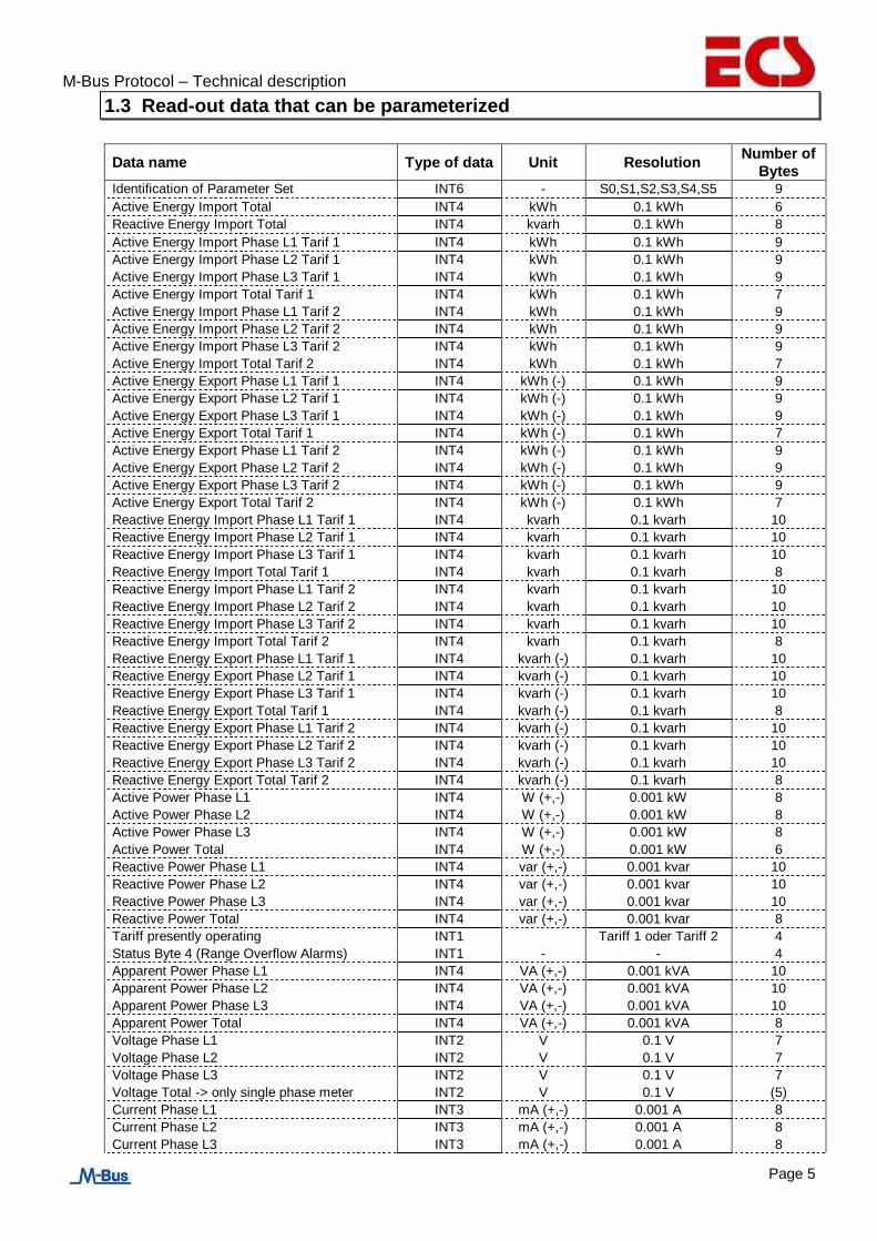
1.3 Read-out data that can be parameterized
Data name Type of data Unit Resolution Number of
Bytes Identification of Parameter Set INT6 - S0,S1,S2,S3,S4,S5 9
Active Energy Import Total INT4 kWh 0.1 kWh 6
Reactive Energy Import Total INT4 kvarh 0.1 kWh 8
Active Energy Import Phase L1 Tarif 1 INT4 kWh 0.1 kWh 9
Active Energy Import Phase L2 Tarif 1 INT4 kWh 0.1 kWh 9
Active Energy Import Phase L3 Tarif 1 INT4 kWh 0.1 kWh 9
Active Energy Import Total Tarif 1 INT4 kWh 0.1 kWh 7
Active Energy Import Phase L1 Tarif 2 INT4 kWh 0.1 kWh 9
Active Energy Import Phase L2 Tarif 2 INT4 kWh 0.1 kWh 9
Active Energy Import Phase L3 Tarif 2 INT4 kWh 0.1 kWh 9
Active Energy Import Total Tarif 2 INT4 kWh 0.1 kWh 7
Active Energy Export Phase L1 Tarif 1 INT4 kWh (-) 0.1 kWh 9
Active Energy Export Phase L2 Tarif 1 INT4 kWh (-) 0.1 kWh 9
Active Energy Export Phase L3 Tarif 1 INT4 kWh (-) 0.1 kWh 9
Active Energy Export Total Tarif 1 INT4 kWh (-) 0.1 kWh 7
Active Energy Export Phase L1 Tarif 2 INT4 kWh (-) 0.1 kWh 9
Active Energy Export Phase L2 Tarif 2 INT4 kWh (-) 0.1 kWh 9
Active Energy Export Phase L3 Tarif 2 INT4 kWh (-) 0.1 kWh 9
Active Energy Export Total Tarif 2 INT4 kWh (-) 0.1 kWh 7
Reactive Energy Import Phase L1 Tarif 1 INT4 kvarh 0.1 kvarh 10
Reactive Energy Import Phase L2 Tarif 1 INT4 kvarh 0.1 kvarh 10
Reactive Energy Import Phase L3 Tarif 1 INT4 kvarh 0.1 kvarh 10
Reactive Energy Import Total Tarif 1 INT4 kvarh 0.1 kvarh 8
Reactive Energy Import Phase L1 Tarif 2 INT4 kvarh 0.1 kvarh 10
Reactive Energy Import Phase L2 Tarif 2 INT4 kvarh 0.1 kvarh 10
Reactive Energy Import Phase L3 Tarif 2 INT4 kvarh 0.1 kvarh 10
Reactive Energy Import Total Tarif 2 INT4 kvarh 0.1 kvarh 8
Reactive Energy Export Phase L1 Tarif 1 INT4 kvarh (-) 0.1 kvarh 10
Reactive Energy Export Phase L2 Tarif 1 INT4 kvarh (-) 0.1 kvarh 10
Reactive Energy Export Phase L3 Tarif 1 INT4 kvarh (-) 0.1 kvarh 10
Reactive Energy Export Total Tarif 1 INT4 kvarh (-) 0.1 kvarh 8
Reactive Energy Export Phase L1 Tarif 2 INT4 kvarh (-) 0.1 kvarh 10
Reactive Energy Export Phase L2 Tarif 2 INT4 kvarh (-) 0.1 kvarh 10
Reactive Energy Export Phase L3 Tarif 2 INT4 kvarh (-) 0.1 kvarh 10
Reactive Energy Export Total Tarif 2 INT4 kvarh (-) 0.1 kvarh 8
Active Power Phase L1 INT4 W (+,-) 0.001 kW 8
Active Power Phase L2 INT4 W (+,-) 0.001 kW 8
Active Power Phase L3 INT4 W (+,-) 0.001 kW 8
Active Power Total INT4 W (+,-) 0.001 kW 6
Reactive Power Phase L1 INT4 var (+,-) 0.001 kvar 10
Reactive Power Phase L2 INT4 var (+,-) 0.001 kvar 10
Reactive Power Phase L3 INT4 var (+,-) 0.001 kvar 10
Reactive Power Total INT4 var (+,-) 0.001 kvar 8
Tariff presently operating INT1 Tariff 1 oder Tariff 2 4
Status Byte 4 (Range Overflow Alarms) INT1 - - 4
Apparent Power Phase L1 INT4 VA (+,-) 0.001 kVA 10
Apparent Power Phase L2 INT4 VA (+,-) 0.001 kVA 10
Apparent Power Phase L3 INT4 VA (+,-) 0.001 kVA 10
Apparent Power Total INT4 VA (+,-) 0.001 kVA 8
Voltage Phase L1 INT2 V 0.1 V 7
Voltage Phase L2 INT2 V 0.1 V 7
Voltage Phase L3 INT2 V 0.1 V 7
Voltage Total -> only single phase meter INT2 V 0.1 V (5)
Current Phase L1 INT3 mA (+,-) 0.001 A 8
Current Phase L2 INT3 mA (+,-) 0.001 A 8
Current Phase L3 INT3 mA (+,-) 0.001 A 8
M-Bus Protocol – Technical description
Page 6
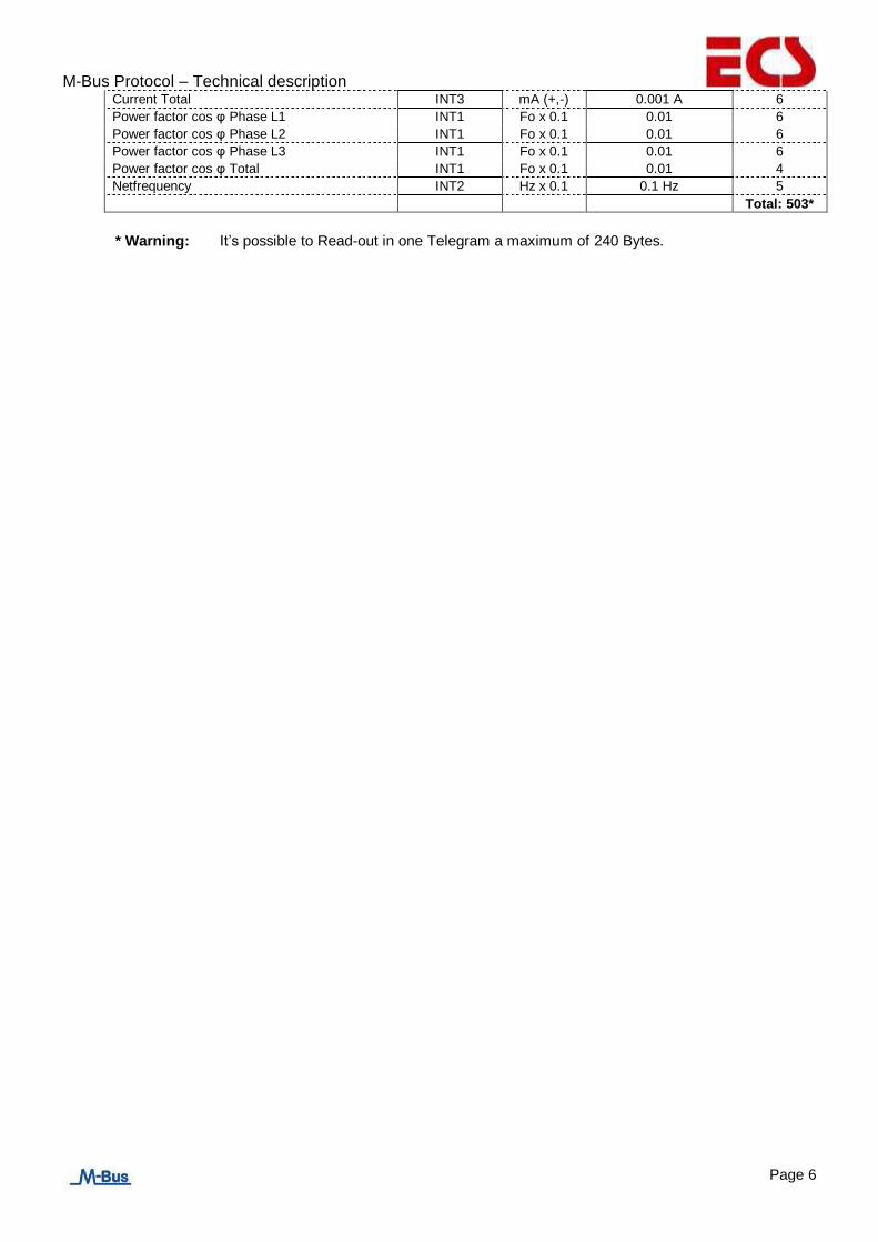
Current Total INT3 mA (+,-) 0.001 A 6
Power factor cos φ Phase L1 INT1 Fo x 0.1 0.01 6
Power factor cos φ Phase L2 INT1 Fo x 0.1 0.01 6
Power factor cos φ Phase L3 INT1 Fo x 0.1 0.01 6
Power factor cos φ Total INT1 Fo x 0.1 0.01 4
Netfrequency INT2 Hz x 0.1 0.1 Hz 5
Total: 503*
* Warning: It’s possible to Read-out in one Telegram a maximum of 240 Bytes.

M-Bus Protocol – Technical description
Page 7
1.4 Read-out data parameterization
1.4.1 Structure of Parameter Set for Read-out Data possible
The Parameter Set identification is a INT6 type (6 Bytes)
S0S1S2S3S4S5 <=
S0 = Parameterset 0 Read-out Data: value: 00 – 7F S1 = Parameterset 1 Read-out Data: value: 00 – FF S2 = Parameterset 2 Read-out Data: value: 00 – FF S3 = Parameterset 3 Read-out Data: value: 00 – FF S4 = Parameterset 4 Read-out Data: value: 00 – FF S5 = Parameterset 5 Read-out Data: value: 00 – FF
S0 = Parameterset 0
xxxx xxx1b : Parameterset Identification xxxx xx1xb : Byte 4 State (Overflow Range Alarms) xxxx x1xxb : Parameterset 1
-> Instead of imported active energy -> Imported reactive energy xxxx 1xxxb : Parameterset 2
-> Instead of exported active energy -> Imported reactive energy xxx1 xxxxb : Parameterset 2
-> Instead of exported active energy -> Exported reactive energy xx1x xxxxb : Parameterset 3
-> Instead of active and reactive power -> Imported reactive energy x1xx xxxxb : Parameterset 3
-> Instead of active and reactive power -> Exported reactive energy 1xxx xxxxb : Parameterset 3
-> Instead of reactive power -> Apparent Power
S1 = Parameterset 1
xxxx xxx1b : Imported active or reactive energy phase L1 Tariff 1 xxxx xx1xb : Imported active or reactive energy phase L2 Tariff 1 xxxx x1xxb : Imported active or reactive energy phase L3 Tariff 1 xxxx 1xxxb : Total imported active or reactive energy Tariff 1 xxx1 xxxxb : Imported active or reactive energy phase L1 Tariff 2 xx1x xxxxb : Imported active or reactive energy phase L2 Tariff 2 x1xx xxxxb : Imported active or reactive energy phase L3 Tariff 2 1xxx xxxxb : Total imported active or reactive energy Tariff 2

M-Bus Protocol – Technical description
Page 8
S2 = Parameterset 2
xxxx xxx1b : Exported active or reactive energy phase L1 Tariff 1 or Imported active or reactive energy phase L1 Tariff 1 xxxx xx1xb : Exported active or reactive energy phase L2 Tariff 1
or Imported active or reactive energy phase L2 Tariff 1 xxxx x1xxb : Exported active or reactive energy phase L3 Tariff 1
or Imported active or reactive energy phase L3 Tariff 1 xxxx 1xxxb : Total exported active or reactive energy Tariff 1
or Total imported active or reactive energy Tariff 1 xxx1 xxxxb : Exported active or reactive energy phase L1 Tariff 2
or Imported active or reactive energy phase L1 Tariff 2 xx1x xxxxb : Exported active or reactive energy phase L2 Tariff 2
or Imported active or reactive energy phase L2 Tariff 2 x1xx xxxxb : Exported active or reactive energy phase L3 Tariff 2
or Imported active or reactive energy phase L3 Tariff 2 1xxx xxxxb : Total exported active or reactive energy Tariff 2
or Total imported active or reactive energy Tariff 2
S3 = Parameterset 3
xxxx xxx1b : Active power phase L1 or Imported or exported reactive energy phase L1 Tariff 1 xxxx xx1xb : Active power phase L2
or Imported or exported reactive energy phase L2 Tariff 1 xxxx x1xxb : Active power phase L3
or Imported or exported reactive energy phase L3 Tariff 1 xxxx 1xxxb : Total active power
or Total imported or exported reactive energy Tariff 1 xxx1 xxxxb : Reactive or Apparent power phase L1
or Imported or exported reactive energy phase L1 Tariff 2 xx1x xxxxb : Reactive or Apparent power phase L2
or Imported or exported reactive energy phase L2 Tariff 2 x1xx xxxxb : Reactive or Apparent power phase L3
or Imported or exported reactive energy phase L3 Tariff 2 1xxx xxxxb : Total Reactive or Apparent power
or Total imported or exported reactive energy Tariff 2
S4 = Parameterset4
xxxx xxx1b : Voltage Phase L1 -> By single phase meter is this the Voltage Total
xxxx xx1xb : Voltage Phase L2 xxxx x1xxb : Voltage Phase L3 xxxx 1xxxb : Active Energy Import Total xxx1 xxxxb : Reactive Energy ImportTotal xx1x xxxxb : Reserve x1xx xxxxb : Netfrequency 1xxx xxxxb : Tariff presently operating

M-Bus Protocol – Technical description
Page 9
S5 = Parameterset5 xxxx xxx1b : Current Phase L1 xxxx xx1xb : Current Phase L2 xxxx x1xxb : Current Phase L3 xxxx 1xxxb : Total Current xxx1 xxxxb : Power factor cos phi Phase L1 xx1x xxxxb : Power factor cos phi Phase L2 x1xx xxxxb : Power factor cos phi Phase L3 1xxx xxxxb : Total power factor cos phi
Example:
Parameter Set Identification (INT6 Typ) = 82 3A 0F 77 07 88, three-phase meter S0 = 82 => 1000 0010b : Status Byte 4 (Overflow Range Alarms)
+ Parameterset 3 -> Instead of Reactive Power
-> all Apparent Power
S1 = 3A => 0011 1010b : Imported active energy phase L2 Tariff 1 + Imported active energy phase L3 Tariff 1 + Total imported active energy Tariff 1 + Imported active energy phase L1 Tariff 2 + Imported active energy phase L2 Tariff 2 S2 = 0F => 0000 1111b : Exported active energy phase L1 Tariff 1 + Exported active energy phase L2 Tariff 1 + Exported active energy phase L3 Tariff 1 + Total exported active energy Tariff 1
S3 = 77 => 0111 0111b : Active Power Phase L1
+ Active Power Phase L2 + Active Power Phase L3 + Apparent Power Phase L1 + Apparent Power Phase L2 + Apparent Power Phase L3
S4 = 07 => 0000 0111b : Voltage Phase L1 + Voltage Phase L2 + Voltage Phase L3 S5 = 88 => 1000 1000b : Total Current + Total Power Factor (cos Phi)

M-Bus Protocol – Technical description
Page 10
1.4.2 Default Parameter Set
These are set by the factory.
This Parameter Set is also loading with the Telegram „Set Parameter Set to Default Read- Out Data“.
Default Parameter Set Identification (INT6 Typ) = 0B FF 88 FF 9F 0F S0 = 0B => 0000 1011b : Parameterset Identification + Status Byte 4 (Range Overflow Alarms)
+ Parameterset 2 Instead of exported active energy ->Imported reactive energy
S0 Total = 13 byte S1 = FF => 1111 1111b : Active - Energy Import Phase L1 Tariff 1 -> Not if single Phase + Active - Energy Import Phase L2 Tariff 1 -> Not if single Phase + Active - Energy Import Phase L3 Tariff 1 -> Not if single Phase + Active - Energy Import Total Tariff 1 + Active - Energy Import Phase L1 Tariff 2 -> Not if single Phase + Active - Energy Import Phase L2 Tariff 2 -> Not if single Phase + Active - Energy Import Phase L3 Tariff f2 -> Not if single Phase + Active - Energy Import Total Tariff 2
S1 Total 3 Phase Energy meter = 68 Byte S1 Total 1 Phase Energy meter = 14 Byte
S2 = 88 => 1000 1000b : Total imported reactive energy Tariff 1 + Total imported reactive energy Tariff 2
S2 Total = 16 Byte
S3 = FF => 1111 1111b : Active - Power Phase L1 -> Not if single Phase + Active - Power Phase L2 -> Not if single Phase + Active - Power Phase L3 -> Not if single Phase + Active - Power Total
+ Reactive - Power Phase L1 -> Not if single Phase + Reactive - Power Phase L2 -> Not if single Phase + Reactive - Power Phase L3 -> Not if single Phase + Reactive - Power Total S3 Total 3 Phase Energy meter = 68 Byte S3 Total 1 Phase Energy meter = 14 Byte
S4 = 9F => 1001 1111b : Voltage Phase L1 -> Not if single Phase or Voltage Total -> Only if 3 Phase + Voltage Phase L2 -> Not if single Phase + Voltage Phase L2 -> Not if single Phase + Active Energy Import Total + Reactive Energy Import Total + Tariff presently operating
S4 Total 3 Phase Energy meter = 39 Byte S4 Total 1 Phase Energy meter = 23 Byte
S5 = 0F => 0000 1111b : Current Phase L1 -> Not if single Phase + Current Phase L2 -> Not if single Phase + Current Phase L3 -> Not if single Phase + Current Total
S5 Total 3 Phase Energy meter = 30 Byte S5 Total 1 Phase Energy meter = 6 Byte
Total: 3 phase energy meter = 224 Byte and single phase energy meter = 86 Byte.

M-Bus Protocol – Technical description
Page 11
2 Telegrams for Parameterization and Read-out Data of M-Bus module
Description of all telegrams that can be used via M-Bus
2.1 Primary Address (A-Field)
Field A (address field) contains the Primary Address of the M-Bus module and is used to identify that module. Field A can have a value between 0 and 255.
2.1.1 Structure of Primary Address (A-Field)
A-Field
(Hex)
Primary
address Description
00 0 Factory setting
01 – FA 1 - 250 Settable primary addresses
FB, FC 251, 252 Reserved for future use
FD 253 Used for processes with secondary addresses
FE 254
Used to send information to all devices connected to the M-Bus network (Broadcast telegram). All the devices respond with a reception confirmation or with their primary address.
FF 255 Used to send information to all devices connected to the M-Bus network (Broadcast telegram). The telegrams with this addressing do not receive replies.
2.2 Secondary Address (UD)
If “FD” is set in A-field, the identification of the M-Bus module occurs on Secondary Address (UD):
2.2.1 Structure of Secondary Address (UD)
Identification number Producer Version Medium
xxxxxxxx mm mm xx 02
- Identification number: 8-digit serial number of M-Bus module (secondary address) => 00000000 – 99999999
- Producer code: 2 Byte constant
- Version number: 1 Byte, firmware version => 01 - FF
- Medium: 1 Byte, constant = electricity => 02

M-Bus Protocol – Technical description
Page 12
2.2.2 Wildcard
The M-Bus module reacts to the requests only if the constant parameters (manufacturer, version, medium) and the identification number coincide with those supplied. "Wildcards" can be used in all 4 of these parameters. The wildcard character is „F“. Individual wildcards cannot be used for constant parameters.
Example: M-Bus module: Identification number = 12345678, producer = XX, version = 12, medium = 02
Ind. sec. (DU) : F2345678, FF FF, 12, 02 => the M-Bus module reacts Ind. sec. (DU): 1234FF78, FF FF, 12, 02 => the M-Bus module reacts Ind. sec. (DU): 12345678, FF FF, 12, 02 => the M-Bus module reacts Ind. sec. (DU): FFF4FFF, FF FF, FF, FF => the M-Bus module reacts Ind. sec. (DU): FFFFFFF, FF FF, FF, FF => All M-Bus modules react on the network Ind. sec. (DU): FFF5FFF, FF FF, FF, FF => The M-Bus module does not react, invalid id. number Ind. sec. (DU): FFFFFFF, FF 14, FF, FF => The M-Bus module does not react, invalid producer Ind. sec. (DU): FFFFFFF, FF FF, 1F, FF => The M-Bus module does not react, invalid version
2.3 Reset M-Bus module access counter (SND_UD)
This telegram resets the M-Bus module access counter, which is set at “0”. The M-Bus module confirms correct reception by means of a reply composed of a single character (ACK = E5). If the telegram is not received properly, the M-Bus module sends no confirmation.
2.3.1 Reset M-Bus module access counter using Primary Address
Byte Nr. Size
(Byte)
Value
(Hex) Description
1 1 68 Start Character Long- Telegram
2 1 03 L- Field
3 1 03 L- Field Repetition
4 1 68 Start- Character Long- Telegram Repetition
5 1 73 C- Field, SND_UD
6 1 xx A- Field, Primary Address (00 – FF = 0 – 255)
7 1 50 CI- Field, Initialise M-Bus module (Set to „0“)
8 1 xx CS Checksum, summed up C-Field to CI- Field incl.
9 1 16 Stop Character
To set the access meter at “0” on all M-Bus modules on the network simultaneously, use 255 as Primary Address in A field (Hex = FF). The M-Bus modules will however not send an Acknowledgement.

M-Bus Protocol – Technical description
Page 13
2.3.2 Reset M-Bus module access counter using Secondary Address
Byte Nr. Size
(Byte)
Value
(Hex) Description
1 1 68 Start Character Long Telegram
2 1 0B L- Field
3 1 0B L- Field Repetition
4 1 68 Start- Character Long Telegram Repetition
5 1 73 C- Field, SND_UD
6 1 FD A- Field, Primary Address to FD = Sekundary Address
7 1 50 CI- Field, Initialise M-Bus module (Set module called to „0“)
8 - 15 8 „UD“ Secondary Address UD (Please see:: „Secondary Address UD“)
16 1 xx CS Checksum, summed up by C-Field to UD incl.
17 1 16 Stop Character

M-Bus Protocol – Technical description
Page 14
2.4 Set baud rate (SND_UD)
This telegram sets the desired baud rate on the M-Bus module. The M-Bus module confirms correct reception by means of a reply composed of a single character (ACK = E5). If the telegram is not received properly, the M-Bus module sends no confirmation. The confirmation reply (ACK) is sent by the M-Bus module with the former baud rate. As soon as “ACK” is sent, the M-Bus module changes to the new baud rate that was set.
2.4.1 Set baud rate using Primary Address
Byte Nr. Size
(Byte)
Value
(Hex) Description
1 1 68 Start Character Long Telegram
2 1 03 L- Field
3 1 03 L- Field Repetition
4 1 68 Start Character, Long Telegram Repetition
5 1 73 C- Field, SND_UD
6 1 xx A- Field, Primary Address (00 – FF = 0 – 255)
7 1 xx
CI- Field, Set new Baudrate B8 : Set Baudrate to 300 Baud B9 : Set Baudrate to 600 Baud BA : Set Baudrate to 1200 Baud BB : Set Baudrate to 2400 Baud -> Manufacturer's Mark BC : Set Baudrate to 4800 Baud BD : Set Baudrate to 9600 Baud
8 1 xx CS Check Sum summed up by C Field, A Field and CI Field
9 1 16 Stop Character
To set the new baud rate on all M-Bus modules on the network simultaneously, use 255 as Primary Address in A field (Hex = FF). The M-Bus modules will however not send an Acknowledgement.
2.4.2 Set baud rate using Secondary Address
Byte Nr. Size
(Byte)
Value
(Hex) Description
1 1 68 Start Character Long Telegram
2 1 0B L- Field
3 1 0B L- Field Repetition
4 1 68 Start Character Long- Telegram Repetition
5 1 73 C- Field, SND_UD
6 1 FD A Field, Primary Address on FD = Secondary Address
7 1 xx
CI- Field, Set new Baudrate B8 : Set Baudrate to 300 Baud B9 : Set Baudrate to 600 Baud BA : Set Baudrate to 1200 Baud BB : Set Baudrate to 2400 Baud -> Manufacturer's Mark BC : Set Baudrate to 4800 Baud BD : Set Baudrate to 9600 Baud
8 - 15 8 „UD“ Secondary Address UD (Please see: „Secondary Address UD“)
16 1 xx CS Check Sum, summed up by C Field, A Field, CI Field and UD.
17 1 16 Stop Character

M-Bus Protocol – Technical description
Page 15
2.5 Set Parameter Set to Default Read-out Data (SND_UD)
This Telegram sets the Parameter Set for the Read-out Data of the Default Parameter Set. The M-Bus module confirms the correct receipt by Single Character Acknowledgement (ACK = E5). If the Telegram has not been correctly received, the M- Bus module will not send an Acknowledgement.
2.5.1 Set Parameter Set to all Read-out Data possible using Primary Address
Byte Nr. Size
(Byte)
Value
(Hex) Description
1 1 68 Start Character Long Telegram
2 1 04 L- Field
3 1 04 L- Field Repetition
4 1 68 Start Character Long Telegram Repetition
5 1 73 C- Field, SND_UD
6 1 xx A- Field, Primary Address (00 – FF = 0 – 255)
7 1 51 CI- Field, New Data from M-Bus Modul
8 1 7F DIF- Field, Set Default Parameterset
9 1 xx CS Checksum, summed up by C-Field to DIF- Field incl.
10 1 16 Stop Character
To set the Default Parameter Set on all M-Bus modules on the network simultaneously, use 255 as Primary Address in A field (Hex = FF). The M-Bus modules will however not send an Acknowledgement.
2.5.2 Set Parameter Set to all Read-out Data possible using Secondary Address
Byte Nr. Size
(Byte)
Value
(Hex) Description
1 1 68 Start Character Long Telegram
2 1 0C L- Field
3 1 0C L- Field Repetition
4 1 68 Start Character Long Telegram Repetition
5 1 73 C- Field, SND_UD
6 1 FD A- Field, Primary Address to FD = Secondary Address
7 1 51 CI- Field, New Data for M-Bus module
8 - 15 8 „UD“ Secondary Address UD (Please see:: „Secondary Address UD“)
16 1 7F DIF- Field, Set Default Parameterset
17 1 xx CS Checksum, summed up by C-Field to DIF- Field incl.
18 1 16 Stop Character

M-Bus Protocol – Technical description
Page 16
2.6 Set Parameter Set to any Read-out Data desired (SND_UD)
This Telegram sets the Parameter Set for Read-out Data of any value desired. For the Structure of the Parameter Set for Read-out Data please see: „Structure of Parameter Set for Read-out Data possible“. The M-Bus module confirms the correct receipt by Single Character Acknowledgement (ACK = E5). If the telegram has not been correctly received the M-Bus module will not send an Acknowledgement.
2.6.1 Set Parameter Set for any Read-out Data desired using Primary Address
Byte Nr. Size
(Byte)
Value
(Hex) Description
1 1 68 Start Charater Long Telegram
2 1 0C L- Field
3 1 0C L- Field Repetition
4 1 68 Start Character Long Telegram Repetition
5 1 73 C- Field, SND_UD
6 1 xx A- Field, Primary Address (00 – FF = 0 – 255)
7 1 51 CI- Field, New Data for M-Bus module
8 1 06 DIF- Field, 48 Bit Integer- Daten (6 Byte)
9 1 FD VIF- Field, Es folgt ein Standart VIFE
10 1 0B VIFE- Field, Standard VIFE = Parameterset- Identification
11 1 „S0“
Parameter Set S1 (00 – FF), Please see: „Structure of Parameter Set of Read-out Data possible“
12 1 „S1“
Parameterset S1 (00 – FF) Please see: „Structure of Parameter Set of Read-out Data possible“
13 1 „S2“
Parameterset S2 (00 – FF) Please see: „Structure of Parameter Set of Read-out Data possible“
14 1 „S3“
Parameterset S3 (00 – FF) Please see: „Structure of Parameter Set of Read-out Data possible“
15 1 „S4“
Parameterset S4 (00 – FF) Please see: „Structure of Parameter Set of Read-out Data possible“
16 1 „S5“
Parameterset S5 (00 - FF) Please see: „Structure of Parameter Set of Read-out Data possible“
17 1 xx CS Checksum, summed up by C-Field to „S5“ incl.
18 1 16 Stop Character
To set the new Parameter Set on all M-Bus modules on the network simultaneously, use 255 as Primary Address in A field (Hex = FF). The M-Bus modules will however not send an Acknowledgement.

M-Bus Protocol – Technical description
Page 17
2.6.2 Set Parameter Set for any Read-out Data desired using Secondary Address
Byte Nr. Size
(Byte)
Value
(Hex) Description
1 1 68 Start Character Long Telegram
2 1 14 L- Field
3 1 14 L- Field Repetition
4 1 68 Start Character Long Telegram Repetition
5 1 73 C- Field, SND_UD
6 1 FD A- Field, Primary Address on FD = Secondary Address
7 1 51 CI- Field, New Data for M-Bus module
8 - 15 8 „UD“ Secondary Address UD (Please see: „Secondary Address UD“)
16 1 06 DIF- Field, 48 Bit Integer Data (6 Byte)
17 1 FD VIF- Field, A Standard VIFE follows
18 1 0B VIFE- Field, Standard VIFE = Parameterset Identification
19 1 „S0“
Parameterset S0 (00 – FF) Please see: „Structure of Parameter Set of Read-out Data possible“
20 1 „S1“
Parameter Set S1 (00 – FF), Please see: „Structure of Parameter Set of Read-out Data possible“
21 1 „S2“
Parameterset S2 (00 – FF), Please see: „Structure of Parameter Set of Read-out Data possible“
22 1 „S3“
Parameterset S3 (00 – 0F), Please see: „Structure of Parameter Set of Read-out Data possible“
23 1 „S4“
Parameterset S4 (00 – FF) Please see: „Structure of Parameter Set of Read-out Data possible“
24 1 „S5“
Parameterset S5 (00 - FF) Please see: „Structure of Parameter Set of Read-out Data possible“
25 1 xx CS Checksum, summed up from C-Field to „S5“ incl.
26 1 16 Stop Character

M-Bus Protocol – Technical description
Page 18
2.7 Set Primary Address (SND_UD)
This Telegram sets a new Primary Address in the M-Bus module. The M-Bus module confirms the correct receipt by Single Character Acknowledgement (ACK = E5). If the telegram has not been correctly received the M-Bus module will not send an Acknowledgement.
2.7.1 Set Primary Address using Primary Address
Byte Nr. Size
(Byte)
Value
(Hex) Description
1 1 68 Start Character Long Telegram
2 1 06 L- Field
3 1 06 L- Field Repetition
4 1 68 Start Character Long Telegram Repetition
5 1 73 C- Field, SND_UD
6 1 xx A- Field, Primary Address (00 – FF = 0 – 255)
7 1 51 CI- Field, New Data for M-Bus module
8 1 01 DIF- Field, 8 Bit Integer - Data (1 Byte)
9 1 7A VIF- Field, Set Primary Address
10 1 xx
New Primary Address:, Range: 00 – FA (0 – 250), Invalid: FB – FF (no action in meter)
11 1 xx
CS Checksum, summed up aus C-Field from C Field to Primary Address incl.
12 1 16 Stop Character
To set the new Primary Address on all M-Bus modules on the network simultaneously, use 255 as Primary Address in A field (Hex = FF). The M-Bus modules will however not send an Acknowledgement.
2.7.2 Set Primary Address using Secondary Address
Byte Nr. Size
(Byte)
Value
(Hex) Description
1 1 68 Start Character Long Telegram
2 1 0E L- Field
3 1 0E L- Field Repetition
4 1 68 Start Character Long Telegram Repetition
5 1 73 C- Field, SND_UD
6 1 FD A- Field, Primary Address on FD = Secondary Address
7 1 51 CI- Field, New Data for M-Bus module
8 - 15 8 „UD“ Secondary Address UD (Please see:: „Secondary Address UD“)
16 1 01 DIF- Field, 8 Bit Integer- Data (1 Byte)
17 1 7A VIF- Field, Set Primary Address
18 1 xx
New Primary Address, Range :00 – FA (0 – 250), Invalid: FB – FF (no action in meter)
19 1 xx CS Checksum, summed up from C Field to Primary Address incl.
20 1 16 Stop Character
M-Bus Protocol – Technical description
Page 19
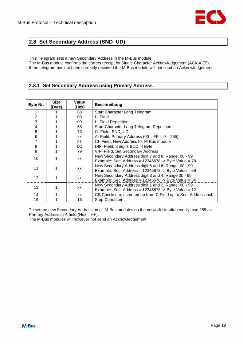
2.8 Set Secondary Address (SND_UD)
This Telegram sets a new Secondary Address in the M-Bus module. The M-Bus module confirms the correct receipt by Single Character Acknowledgement (ACK = E5). If the telegram has not been correctly received the M-Bus module will not send an Acknowledgement.
2.8.1 Set Secondary Address using Primary Address
Byte Nr. Size
(Byte)
Value
(Hex) Beschreibung
1 1 68 Start Character Long Telegram
2 1 09 L- Field
3 1 09 L- Field Repetition
4 1 68 Start Character Long Telegram Repetition
5 1 73 C- Field, SND_UD
6 1 xx A- Field, Primary Address (00 – FF = 0 – 255)
7 1 51 CI- Field, New Address for M-Bus module
8 1 0C DIF- Field, 8 digits BCD, 4 Byte
9 1 79 VIF- Field, Set Secondary Address
10 1 xx
New Secondary Address digit 7 and 8, Range: 00 - 99 Example: Sec. Address = 12345678 -> Byte Value = 78
11 1 xx
New Secondary Address digit 5 and 6, Range: 00 - 99 Example: Sec. Address = 12345678 -> Byte Value = 56
12 1 xx
New Secondary Address digit 3 and 4, Range 00 - 99 Example: Sec. Address = 12345678 -> Byte Value = 34
13 1 xx
New Secondary Address digit 1 and 2, Range: 00 - 99 Example: Sec. Address = 12345678 -> Byte Value = 12
14 1 xx CS Checksum, summed up from C Field up to Sec. Address incl.
15 1 16 Stop Character
To set the new Secondary Address on all M-Bus modules on the network simultaneously, use 255 as Primary Address in A field (Hex = FF). The M-Bus modules will however not send an Acknowledgement.

M-Bus Protocol – Technical description
Page 20
2.8.2 Set Secondary Address using Secondary Address
Byte Nr. Size
(Byte)
Value
(Hex) Beschreibung
1 1 68 Start Character Long Telegram
2 1 11 L- Field
3 1 11 L- Field Repetition
4 1 68 Start Character Long Telegram Repetition
5 1 73 C- Field, SND_UD
6 1 FD A- Field, Primary Address on FD = Secondary Address
7 1 51 CI- Field, New Data for M-Bus module
8 - 15 8 „UD“ Secondary Address UD (Please see: „Secondary Address UD“)
16 1 0C DIF- Field, 8 digits BCD, 4 Byte
17 1 79 VIF- Field, Set Secondary Address
18 1 xx
New Secondary Address digits 7 and 8, Range: 00 - 99 Beispiel: Sec. Address = 12345678 -> Byte Value = 78
19 1 xx
New Secondary Address digits 5 and 6, Range: 00 - 99 Example: Sec. Address = 12345678 -> Byte Value = 56
20 1 xx
New Secondary Address digits 3 and 4, Range: 00 - 99 Example: Sec. Address = 12345678 -> Byte Value = 34
21 1 xx
New Secondary Address digits 1 and 2, Range: 00 - 99 Example: Sec. Address = 12345678 -> Byte Value = 12
22 1 xx CS Checksum, summed up from C Field to Sec. Address incl.
23 1 16 Stop Character

M-Bus Protocol – Technical description
Page 21
2.9 Set Secondary Address and Manufacturer’s Mark (SND_UD)
This Telegram sets a new Secondary Address and a new Manufacturer’s Mark. The M-Bus module confirms the correct receipt by Single Character Acknowledgement (ACK = E5). If the telegram has not been correctly received the M-Bus module will not send an Acknowledgement.
2.9.1 Set Secondary Address and Manufacturer’s Mark using Primary Address
Byte Nr. Size
(Byte)
Value
(Hex) Beschreibung
1 1 68 Start Character Long Telegram
2 1 0D L- Field
3 1 0D L- Field Repetition
4 1 68 Start Character Long Telegram Repetition
5 1 73 C- Field, SND_UD
6 1 xx A- Field, Primary Address (00 – FF = 0 – 255)
7 1 51 CI- Field, New Data for M-Bus module
8 1 07 DIF- Field, 64 Bit Integer, 8 Byte
9 1 79 VIF- Field, Set Secondary Address and Manufacturer’s Mark
10 1 xx
New Secondary Address digits 7 and 8, Range: 00 – 99 Example: Sec. Address = 12345678 -> Byte Value = 78
11 1 xx
New Secondary Address digits 5 and 6, Range: 00 – 99 Example: Sec. Address = 12345678 -> Byte Value = 56
12 1 xx
New Secondary Address digits 3 and 4, Range: 00 – 99 Example: Sec. Address = 12345678 -> Byte Value = 34
13 1 xx
New Secondary Address digits 1 and 2, Range: 00 – 99 Example: Sec. Address = 12345678 -> Byte Value = 12
14 1 xx New Manufacturer’s Mark Byte 2, Range: 00 – FF Example: Manufacturer = 14 73 (ECS) -> Byte- Value = 73
15 1 xx New Manufacturer’s Mark Byte 1, Range: 00 – FF Example: Manufacturer = 14 73 (ECS) -> Byte- Value = 14
16 1 xx Version; This Parameter cannot be changed => Setting: Any Value 00 – FF
17 1 xx Medium; This Parameter is fixed to 02 and cannot be changed. => Setting: Any Value 00 - FF.
18 1 xx CS Checksum, summed up from C Field to Medium inclusive
19 1 16 Stop Character
To set the new Secondary Address and the new Manufacturer’s Mark on all M-Bus modules on the network simultaneously, use 255 as Primary Address in A field (Hex = FF). The M-Bus modules will however not send an Acknowledgement.

M-Bus Protocol – Technical description
Page 22
2.9.2 Set Secondary Address and Manufacturer’s Mark using Secondary Address
Byte Nr. Size
(Byte)
Value
(Hex) Description
1 1 68 Start Character Long Telegram
2 1 15 L- Field
3 1 15 L- Field Repetition
4 1 68 Start Character Long Telegram Repetition
5 1 73 C- Field, SND_UD
6 1 FD A- Field, Primary Address on FD = Secondary Address
7 1 51 CI- Field, New Data for M-Bus module
8 - 15 8 „UD“ Secondary Address UD (Please see: „Secondary Address UD“)
16 1 07 DIF- Field, 64 Bit Integer, 8 Byte
17 1 79 VIF- Field, Set Secondary Address and Manufacturer’s Mark
18 1 xx
New Secondary Address digits 7 and 8, Range: 00 – 99 Example: Sec. Address = 12345678 -> Byte Value = 78
19 1 xx
New Secondary Address digits 5 and 6, Range: 00 – 99 Example: Sec. Address = 12345678 -> Byte Value = 56
20 1 xx
New Secondary Address digits 3 and 4, : Range 00 – 99 Example: Sec. Address = 12345678 -> B Range Byte Value = 34
21 1 xx
New Secondary Address digits 1 and 2, : 00 – 99 Example: Sec. Address = 12345678 -> Byte Value = 12
22 1 xx New Manufacturer’s Mark Byte 2, Range: 00 – FF Example: Manufacturer = 14 73 (ECS) -> Byte- Value = 73
23 1 xx New Manufacturer’s Mark Byte 1, Range: 00 – FF Example: Manufacturer = 14 73(ECS) => Byte Value = 14
24 1 xx Version; This Parameter cannot be changed. => Setting: Any Value 00 – FF
25 1 xx Medium; This Parameter is fixed to 02 and cannot be changed. => Setting: Any Value 00 – FF
26 1 xx CS Checksum, summed up from C Field to Medium incl.
27 1 16 Stop Character
M-Bus Protocol – Technical description
Page 23
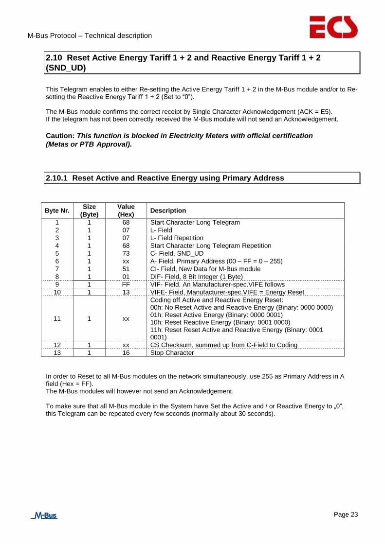
2.10 Reset Active Energy Tariff 1 + 2 and Reactive Energy Tariff 1 + 2
(SND_UD)
This Telegram enables to either Re-setting the Active Energy Tariff 1 + 2 in the M-Bus module and/or to Re-setting the Reactive Energy Tariff 1 + 2 (Set to “0”). The M-Bus module confirms the correct receipt by Single Character Acknowledgement (ACK = E5). If the telegram has not been correctly received the M-Bus module will not send an Acknowledgement.
Caution: This function is blocked in Electricity Meters with official certification
(Metas or PTB Approval).
2.10.1 Reset Active and Reactive Energy using Primary Address
Byte Nr. Size
(Byte)
Value
(Hex) Description
1 1 68 Start Character Long Telegram
2 1 07 L- Field
3 1 07 L- Field Repetition
4 1 68 Start Character Long Telegram Repetition
5 1 73 C- Field, SND_UD
6 1 xx A- Field, Primary Address (00 – FF = 0 – 255)
7 1 51 CI- Field, New Data for M-Bus module
8 1 01 DIF- Field, 8 Bit Integer (1 Byte)
9 1 FF VIF- Field, An Manufacturer-spec.VIFE follows
10 1 13 VIFE- Field, Manufacturer-spec.VIFE = Energy Reset
11 1 xx
Coding off Active and Reactive Energy Reset: 00h: No Reset Active and Reactive Energy (Binary: 0000 0000) 01h: Reset Active Energy (Binary: 0000 0001) 10h: Reset Reactive Energy (Binary: 0001 0000) 11h: Reset Reset Active and Reactive Energy (Binary: 0001 0001)
12 1 xx CS Checksum, summed up from C-Field to Coding
13 1 16 Stop Character
In order to Reset to all M-Bus modules on the network simultaneously, use 255 as Primary Address in A field (Hex = FF). The M-Bus modules will however not send an Acknowledgement.
To make sure that all M-Bus module in the System have Set the Active and / or Reactive Energy to „0“, this Telegram can be repeated every few seconds (normally about 30 seconds).

M-Bus Protocol – Technical description
Page 24
2.10.2 Reset Active and Reactive Energy using Secondary Address
Byte Nr. Size
(Byte)
Value
(Hex) Description
1 1 68 Start Character Long Telegram
2 1 0F L- Field
3 1 0F L- Field Repetition
4 1 68 Start Character Long Telegram Repetition
5 1 73 C- Field, SND_UD
6 1 FD A- Field, Primary Address on FD = Secondary Address
7 1 51 CI- Field, New Data for M-Bus module
8 - 15 8 „UD“ Secondary Address UD (Please see: „Secondary Address UD“)
16 1 01 DIF- Field, 8 Bit Integer (1 Byte)
17 1 FF VIF- Field, An Manufacturer-spec.VIFE follows
18 1 13 VIFE- Field, Manufacturer-spec.VIFE = Energy Reset
19 1 xx
Coding off Active and Reactive Energy Reset: 00h: No Reset Active and Reactive Energy (Binary: 0000 0000) 01h: Reset Active Energy (Binary: 0000 0001) 10h: Reset Reactive Energy (Binary: 0001 0000) 11h: Reset Reset Active and Reactive Energy (Binary: 0001 0001)
20 1 xx CS Checksum, summed up from C-Field to Coding
21 1 16 Stop Character

M-Bus Protocol – Technical description
Page 25
2.11 Select M-Bus Module using Secondary Address (SND_UD)
This Telegram selects M-Bus module. The M-Bus module confirms the correct receipt by Single Character Acknowledgement (ACK = E5) and switch into Selection Mode. If the telegram has not been correctly received the M-Bus module will not send an Acknowledgement. In Selection Mode the M-Bus module is ready to transmit the entire Read-out Data after receiving the Telegram „Transmit Read-out Data“ (Short Telegram REQ_UD2 with A- Field on FD). In Selection Mode the M-Bus module accepts also all telegrams with Primary Address on FD (A-Field on FD) The M-Bus module switch back to Normal Mode by receiving an invalid telegram or by receiving the telegram “ Initialisation of M-Bus module”
2.11.1 Select M-Bus Module using Secondary Address
Byte Nr. Size
(Byte)
Value
(Hex) Description
1 1 68 Start Character Long Telegram
2 1 0B L- Field
3 1 0B L- Field Repetition
4 1 68 Start Character Long Telegram Repetition
5 1 73 C- Field, SND_UD
6 1 FD A- Field, Primary Address on FD = Secondary Address
7 1 52 CI- Field, Selection of M-Bus module
8 - 15 8 „UD“ Secondary Address UD (Please see: „Secondary Address UD“)
16 1 xx CS Checksum, summed up from C-Field to Sekundary Address
17 1 16 Stop Character
M-Bus Protocol – Technical description
Page 26
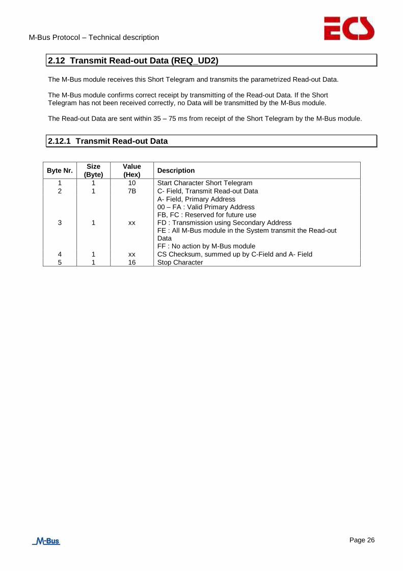
2.12 Transmit Read-out Data (REQ_UD2)
The M-Bus module receives this Short Telegram and transmits the parametrized Read-out Data. The M-Bus module confirms correct receipt by transmitting of the Read-out Data. If the Short Telegram has not been received correctly, no Data will be transmitted by the M-Bus module. The Read-out Data are sent within 35 – 75 ms from receipt of the Short Telegram by the M-Bus module.
2.12.1 Transmit Read-out Data
Byte Nr. Size
(Byte)
Value
(Hex) Description
1 1 10 Start Character Short Telegram
2 1 7B C- Field, Transmit Read-out Data
3 1 xx
A- Field, Primary Address 00 – FA : Valid Primary Address FB, FC : Reserved for future use FD : Transmission using Secondary Address FE : All M-Bus module in the System transmit the Read-out Data FF : No action by M-Bus module
4 1 xx CS Checksum, summed up by C-Field and A- Field
5 1 16 Stop Character

M-Bus Protocol – Technical description
Page 27
2.12.2 Telegram of Read-out Data by M-Bus module (RSP_UD)
- Bytes No. 8 – 19 are the firm Data Record Header for every M-Bus module.
- Bytes No. 20 – YY are the Read-out Data defined in the Parameter Set.
Byte Nr. Size
(Byte)
Value
(Hex) Description
1 1 68 Start Character Long Telegram
2 1 xx
L- Field, corresponding to number of Read-out Data parametrised
3 1 xx L- Field Repetition
4 1 68 Start Character Long Telegram Repetition
5 1 08 C- Field, Transmit Data of M-Bus module
6 1 xx A- Field, Primary Address (00 – FA = 0 – 250)
7 1 72 CI- Field, Read-out Data of M-Bus module
8 - 11 4 xxxxxxxx 8-digit Serial Number of M-Bus module (Sec. Address)
12 + 13 2 xx xx Manufacturer’s Mark
14 1 xx Version Number of M-Bus module Firmware (00 – FF)
15 1 02 Medium Electricity
16 1 xx Meter called upon, at each call on M-Bus module + 1 (00 – FF -> 00)
17 1 xx
Shows the M-Bus module Status. Please see „Structure of Error Flags Data Transmission from Meter to M-Bus module“ and „Structure of Error Flags in M-Bus module“
18 + 19 2 00 00 Signature. For M-Bus module always on „0000“
20 - YY 0 - EA xx….xx Read-out Data parametrised. Please see:” Structure of Telegram of Read-out Data possible“
YY + 1 1 xx CS Check Sum, summed up from C Field to End of „Read-out Data parametrised”
YY + 2 1 16 Stop Character

M-Bus Protocol – Technical description
Page 28
2.12.3 Structure of Telegram for Read-out Data possible
The M-Bus module transmits Read-out Data to the Master depending on the Parameter Set. A summary of the options is shown under „Structure of Parameterset for Read-out Data possible“.
2.12.3.1 Parameterset Identification
Byte Nr. Size
(Byte)
Value
(Hex) Description
YY 1 06 DIF, 48 Bit Integer, 6 Byte
YY + 1 1 FD VIF, followed by a Standart VIFE
YY + 2 1 0B Parameterset Identification
YY + 3 1 „S0“
Parameterset S0 (00 – FF) Please see: „Structure of Parameter Set of Read-out Data possible“
YY + 4 1 „S1“
Parameterset S1 (00 – FF) Please see: „Structure of Parameter Set of Read-out Data possible“
YY + 5 1 „S2“
Parameterset S2 (00 – FF) Please see: „Structure of Parameter Set of Read-out Data possible“
YY + 6 1 „S3“
Parameterset S3 (00 – FF) Please see: „Structure of Parameter Set of Read-out Data possible“
YY + 7 1 „S4“
Parameterset S4 (00 – FF) Please see: „Structure of Parameter Set of Read-out Data possible“
YY + 8 1 „S5“
Parameterset S5 (00 – FF) Please see: „Structure of Parameter Set of Read-out Data possible“
2.12.3.2 Active Energy Import Total
Byte Nr. Size
(Byte)
Value
(Hex) Description
YY 1 04 DIF, 32 Bit Integer, 4 Byte
YY + 1 1 05 VIF, Active Energy Total
YY + 2 - YY + 5
4 xxxxxxxx Active Energy Import Total

M-Bus Protocol – Technical description
Page 29
2.12.3.3 Reactive Energy Import Total
Byte Nr. Size
(Byte)
Value
(Hex) Description
YY 1 84 DIF, 32 Bit Integer, 4 Byte; Followed by a DIFE
YY + 1 1 80 DIFE, Followed by a further DIFE
YY + 2 1 40 DIFE, Reactive Register
YY + 3 1 05 VIF, Reactive Energy Total
YY + 4 - YY + 7
4 xxxxxxxx Reactive Energy Import Total
2.12.3.4 Active Energy Import Phase L1, L2 and L3 Tariff 1
Byte Nr. Size
(Byte)
Value
(Hex) Description
YY 1 84 DIF, 32 Bit Integer, 4 Byte; Followed by a DIFE
YY + 1 1 10 DIFE, Tariff 1
YY + 2 1 85 VIF, Active Energy, Followed by a further VIFE
YY + 3 1 FF VIFE, Followed by an Manufacturer-spec.VIFE
YY + 4 1 0x
Manufacturer-spec.VIFE: 01 : Phase L1 02 : Phase L2 03 : Phase L3
YY + 5 - YY + 8
4 xxxxxxxx Active Energy Import Phase L1, L2 or L3
2.12.3.5 Active Energy Import Total Tariff 1
Byte Nr. Size
(Byte)
Value
(Hex) Description
YY 1 84 DIF, 32 Bit Integer, 4 Byte; Followed by a DIFE
YY + 1 1 10 DIFE, Tariff 1
YY + 2 1 05 VIF, Active Energy
YY + 3 - YY + 6
4 xxxxxxxx Active Energy Import Total Tariff 1
M-Bus Protocol – Technical description
Page 30
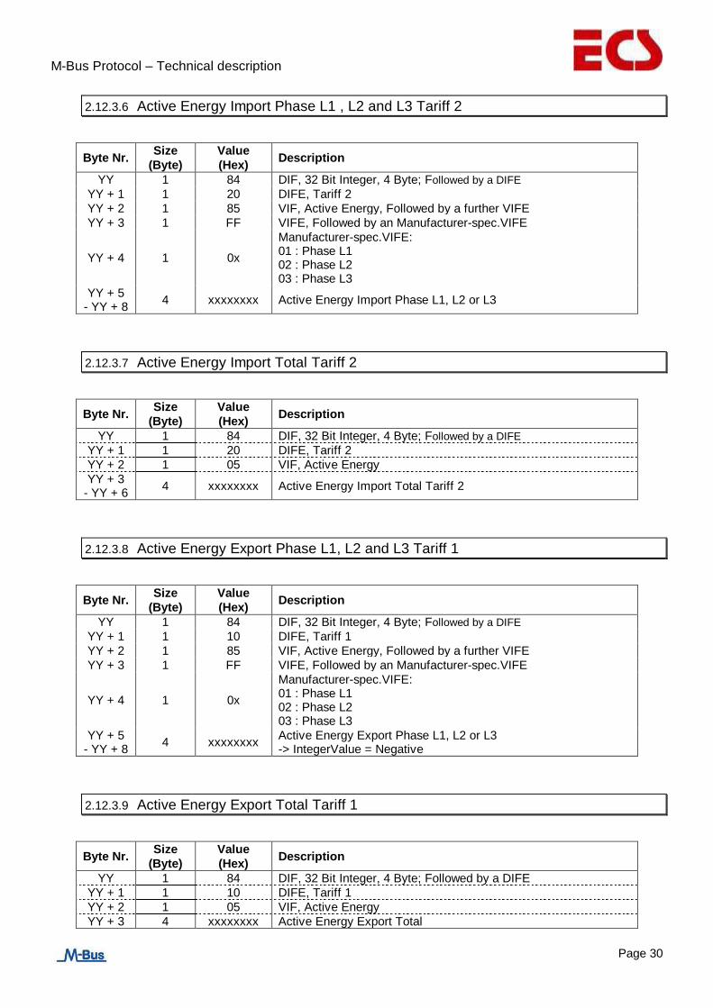
2.12.3.6 Active Energy Import Phase L1 , L2 and L3 Tariff 2
Byte Nr. Size
(Byte)
Value
(Hex) Description
YY 1 84 DIF, 32 Bit Integer, 4 Byte; Followed by a DIFE
YY + 1 1 20 DIFE, Tariff 2
YY + 2 1 85 VIF, Active Energy, Followed by a further VIFE
YY + 3 1 FF VIFE, Followed by an Manufacturer-spec.VIFE
YY + 4 1 0x
Manufacturer-spec.VIFE: 01 : Phase L1 02 : Phase L2 03 : Phase L3
YY + 5 - YY + 8
4 xxxxxxxx Active Energy Import Phase L1, L2 or L3
2.12.3.7 Active Energy Import Total Tariff 2
Byte Nr. Size
(Byte)
Value
(Hex) Description
YY 1 84 DIF, 32 Bit Integer, 4 Byte; Followed by a DIFE
YY + 1 1 20 DIFE, Tariff 2
YY + 2 1 05 VIF, Active Energy
YY + 3 - YY + 6
4 xxxxxxxx Active Energy Import Total Tariff 2
2.12.3.8 Active Energy Export Phase L1, L2 and L3 Tariff 1
Byte Nr. Size
(Byte)
Value
(Hex) Description
YY 1 84 DIF, 32 Bit Integer, 4 Byte; Followed by a DIFE
YY + 1 1 10 DIFE, Tariff 1
YY + 2 1 85 VIF, Active Energy, Followed by a further VIFE
YY + 3 1 FF VIFE, Followed by an Manufacturer-spec.VIFE
YY + 4 1 0x
Manufacturer-spec.VIFE: 01 : Phase L1 02 : Phase L2 03 : Phase L3
YY + 5 - YY + 8
4 xxxxxxxx
Active Energy Export Phase L1, L2 or L3 -> IntegerValue = Negative
2.12.3.9 Active Energy Export Total Tariff 1
Byte Nr. Size
(Byte)
Value
(Hex) Description
YY 1 84 DIF, 32 Bit Integer, 4 Byte; Followed by a DIFE
YY + 1 1 10 DIFE, Tariff 1
YY + 2 1 05 VIF, Active Energy
YY + 3 4 xxxxxxxx Active Energy Export Total

M-Bus Protocol – Technical description
Page 31
- YY + 6 -> IntegerValue = Negative
2.12.3.10 Active Energy Export Phase L1, L2 and L3 Tariff 2
Byte Nr. Size
(Byte)
Value
(Hex) Description
YY 1 84 DIF, 32 Bit Integer, 4 Byte; Followed by a DIFE
YY + 1 1 20 DIFE, Tariff 2
YY + 2 1 85 VIF, Active Energy, Followed by a further VIFE
YY + 3 1 FF VIFE, Followed by an Manufacturer-spec.VIFE
YY + 4 1 0x
Manufacturer-spec.VIFE: 01 : Phase L1 02 : Phase L2 03 : Phase L3
YY + 5 - YY + 8
4 xxxxxxxx
Active Energy Export Phase L1, L2 or L3 -> IntegerValue = Negative
2.12.3.11 Active Energy Export Total Tariff 2
Byte Nr. Size
(Byte)
Value
(Hex) Description
YY 1 84 DIF, 32 Bit Integer, 4 Byte; Followed by a DIFE
YY + 1 1 20 DIFE, Tariff 2
YY + 2 1 05 VIF, Active Energy
YY + 3 - YY + 6
4 xxxxxxxx
Active Energy Export Total -> IntegerValue = Negative
2.12.3.12 Reactive Energy Import Phase L1, L2 and L3 Tariff 1
Byte Nr. Size
(Byte)
Value
(Hex) Description
YY 1 84 DIF, 32 Bit Integer, 4 Byte; Followed by a DIFE
YY + 1 1 90 DIFE, Tariff 1 ; Followed by a further DIFE
YY + 2 1 40 DIFE, Reactive Value
YY + 3 1 85 VIF, Reactive Energy; Followed by a further VIFE
YY + 4 1 FF VIFE, Followed by an Manufacturer-spec.VIFE
YY + 5 1 0x
Manufacturer-spec.VIFE: 01 : Phase L1 02 : Phase L2 03 : Phase L3
YY + 6 - YY + 9
4 xxxxxxxx Reactive Energy Import Phase L1, L2 or L3

M-Bus Protocol – Technical description
Page 32
2.12.3.13 Reactive Energy Import Total Tariff 1
Byte Nr. Size
(Byte)
Value
(Hex) Description
YY 1 84 DIF, 32 Bit Integer, 4 Byte; Followed by a DIFE
YY + 1 1 90 DIFE, Total Tariff 1; Followed by a further DIFE
YY + 2 1 40 DIFE, Reactive Value
YY + 3 1 05 VIF, Reactive Energy
YY + 4 - YY + 7
4 xxxxxxxx Reactive Energy Import Total
2.12.3.14 Reactive Energy Import Phase L1, L2 and L3 Tariff 2
Byte Nr. Size
(Byte)
Value
(Hex) Description
YY 1 84 DIF, 32 Bit Integer, 4 Byte; Followed by a DIFE
YY + 1 1 A0 DIFE, Tariff 2 ; Followed by a further DIFE
YY + 2 1 40 DIFE, Reactive Value
YY + 3 1 85 VIF, Reactive Energy; Followed by a further VIFE
YY + 4 1 FF VIFE, Followed by an Manufacturer-spec.VIFE
YY + 5 1 0x
Manufacturer-spec.VIFE: 01 : Phase L1 02 : Phase L2 03 : Phase L3
YY + 6 - YY + 9
4 xxxxxxxx Reactive Energy Import Phase L1, L2 or L3
2.12.3.15 Reactive Energy Import Total Tariff 2
Byte Nr. Size
(Byte)
Value
(Hex) Description
YY 1 84 DIF, 32 Bit Integer, 4 Byte; Followed by a DIFE
YY + 1 1 A0 DIFE, Total Tariff 2; Followed by a further DIFE
YY + 2 1 40 DIFE, Reactive Value
YY + 3 1 05 VIF, Reactive Energy
YY + 4 - YY + 7
4 xxxxxxxx Reactive Energy Import Total

M-Bus Protocol – Technical description
Page 33
2.12.3.16 Reactive Energy Export Phase L1, L2 and L3 Tariff 1
Byte Nr. Size
(Byte)
Value
(Hex) Description
YY 1 84 DIF, 32 Bit Integer, 4 Byte; Followed by a DIFE
YY + 1 1 90 DIFE, Tariff 1 ; Followed by a further DIFE
YY + 2 1 40 DIFE, Reactive Value
YY + 3 1 85 VIF, Reactive Energy; Followed by a further VIFE
YY + 4 1 FF VIFE, Followed by an Manufacturer-spec.VIFE
YY + 5 1 0x
Manufacturer-spec.VIFE: 01 : Phase L1 02 : Phase L2 03 : Phase L3
YY + 6 - YY + 9
4 xxxxxxxx
Reactive Energy Export Phase L1, L2 or L3 -> IntegerValue = Negative
2.12.3.17 Reactive Energy Export Total Tariff 1
Byte Nr. Size
(Byte)
Value
(Hex) Description
YY 1 84 DIF, 32 Bit Integer, 4 Byte; Followed by a DIFE
YY + 1 1 90 DIFE, Total Tariff 1; Followed by a further DIFE
YY + 2 1 40 DIFE, Reactive Value
YY + 3 1 05 VIF, Reactive Energy
YY + 4 - YY + 7
4 xxxxxxxx
Reactive Energy Export Total -> IntegerValue = Negative
2.12.3.18 Reactive Energy Export Phase L1, L2 and L3 Tariff 2
Byte Nr. Size
(Byte)
Value
(Hex) Description
YY 1 84 DIF, 32 Bit Integer, 4 Byte; Followed by a DIFE
YY + 1 1 A0 DIFE, Tariff 2 ; Followed by a further DIFE
YY + 2 40 DIFE, Reactive Value
YY + 3 1 85 VIF, Reactive Energy; Followed by a further VIFE
YY + 4 1 FF VIFE, Followed by an Manufacturer-spec.VIFE
YY + 5 1 0x
Manufacturer-spec.VIFE: 01 : Phase L1 02 : Phase L2 03 : Phase L3
YY + 6 - YY + 9
4 xxxxxxxx
Reactive Energy Export Phase L1, L2 or L3 -> IntegerValue = Negative

M-Bus Protocol – Technical description
Page 34
2.12.3.19 Reactive Energy Export Total Tariff 2
Byte Nr. Size
(Byte)
Value
(Hex) Description
YY 1 84 DIF, 32 Bit Integer, 4 Byte; Followed by a DIFE
YY + 1 1 A0 DIFE, Total Tariff 2; Followed by a further DIFE
YY + 2 1 40 DIFE, Reactive Value
YY + 3 1 05 VIF, Reactive Energy
YY + 4 - YY + 7
4 xxxxxxxx
Reactive Energy Export Total -> IntegerValue = Negative
2.12.3.20 Active Power Phase L1, L2 and L3
Byte Nr. Size
(Byte)
Value
(Hex) Description
YY 1 04 DIF, 32 Bit Integer, 4 Byte
YY + 1 1 AB VIF, Active Power; Followed by a further VIFE
YY + 2 1 FF VIFE, Followed by an Manufacturer-spec.VIFE
YY + 3 1 0x
Manufacturer-spec.VIFE: 01 : Phase L1 02 : Phase L2 03 : Phase L3
YY + 4 - YY + 7
4 xxxxxxxx Active Power Phase L1, L2 or L3
2.12.3.21 Active Power Total
Byte Nr. Size
(Byte)
Value
(Hex) Description
YY 1 04 DIF, 32 Bit Integer, 4 Byte
YY + 1 1 2B VIF, Active Power
YY + 2 - YY + 5
4 xxxxxxxx Active Power Total
2.12.3.22 Reactive Power Phase L1, L2 and L3
Byte Nr. Size
(Byte)
Value
(Hex) Description
YY 1 84 DIF, 32 Bit Integer, 4 Byte; Followed by a DIFE
YY + 1 1 80 DIFE, Total; Followed by a further DIFE
YY + 2 1 40 DIFE, Reactive Value
YY + 3 1 AB VIF, Reactive Power; Followed by a further VIFE
YY + 4 1 FF VIFE, Followed by an Manufacturer-spec.VIFE
YY + 5 1 0x
Manufacturer-spec.VIFE: 01 : Phase L1 02 : Phase L2 03 : Phase L3
YY + 6 - YY + 9
4 xxxxxxxx Reactive Power Phase L1, L2 or L3

M-Bus Protocol – Technical description
Page 35
2.12.3.23 Reactive Power Total
Byte Nr. Size
(Byte)
Value
(Hex) Description
YY 1 84 DIF, 32 Bit Integer, 4 Byte; Followed by a DIFE
YY + 1 1 80 DIFE, Total; Followed by a further DIFE
YY + 2 1 40 DIFE, Reactive- Value
YY + 3 1 2B VIF, Reactive Power
YY + 4 - YY + 7
4 xxxxxxxx Reactive Power Total
2.12.3.24 Apparent Power Phase L1, L2 and L3
Byte Nr. Size
(Byte)
Value
(Hex) Description
YY 1 84 DIF, 32 Bit Integer, 4 Byte; Followed by a DIFE
YY + 1 1 C0 DIFE, Total; Followed by a further DIFE
YY + 2 1 40 DIFE, Apparent Value
YY + 3 1 AB VIF, Apparent Power; Followed by a further VIFE
YY + 4 1 FF VIFE, Followed by an Manufacturer-spec.VIFE
YY + 5 1 0x
Manufacturer-spec.VIFE: 01 : Phase L1 02 : Phase L2 03 : Phase L3
YY + 6 - YY + 9
4 xxxxxxxx Apparent Power Phase L1, L2 or L3
2.12.3.25 Apparent Power Total
Byte Nr. Size
(Byte)
Value
(Hex) Description
YY 1 84 DIF, 32 Bit Integer, 4 Byte; Followed by a DIFE
YY + 1 1 C0 DIFE, Total; Followed by a further DIFE
YY + 2 1 40 DIFE, Apparent Value
YY + 3 1 2B VIF, Apparent Power
YY + 4 - YY + 7
4 xxxxxxxx Apparent Power Total

M-Bus Protocol – Technical description
Page 36
2.12.3.26 Voltage Phase L1, L2 and L3
Byte Nr. Size
(Byte)
Value
(Hex) Description
YY 1 02 DIF, 16 Bit Integer, 2 Byte
YY + 1 1 FD VIF, Followed by a VIFE
YY + 2 1 C8 VIFE = Voltage; Followed by a further VIFE
YY + 3 1 FF VIFE, Followed by an Manufacturer-spec.VIFE
YY + 4 1 0x
Manufacturer-spec.VIFE: 01 : Phase L1 02 : Phase L2 03 : Phase L3
YY + 5 - YY + 6
2 xxxx Voltage Phase L1, L2 or L3
2.12.3.27 Voltage Total single Phase Meter
Byte Nr. Size
(Byte)
Value
(Hex) Description
YY 1 02 DIF, 16 Bit Integer, 2 Byte
YY + 1 1 FD VIF, Followed by a VIFE
YY + 2 1 48 VIFE = Voltage
YY + 3 - YY + 4
2 xxxx Voltage Total
2.12.3.28 Current Phase L1, L2 and L3
Byte Nr. Size
(Byte)
Value
(Hex) Description
YY 1 03 DIF, 23 Bit Integer, 3 Byte
YY + 1 1 FD VIF, Followed by a VIFE
YY + 2 1 D9 VIFE = Current; Followed by a further VIFE
YY + 3 1 FF VIFE, Followed by an Manufacturer-spec.VIFE
YY + 4 1 0x
Manufacturer-spec.VIFE: 01 : Phase L1 02 : Phase L2 03 : Phase L3
YY + 5 - YY + 7
3 xxxxxx Current Phase L1, L2 or L3

M-Bus Protocol – Technical description
Page 37
2.12.3.29 Current Total
Byte Nr. Size
(Byte)
Value
(Hex) Description
YY 1 03 DIF, 23 Bit Integer, 3 Byte
YY + 1 1 FD VIF, Followed by a VIFE
YY + 2 1 59 VIFE = Current Total
YY + 3 - YY + 5
3 xxxxxx Current Total
2.12.3.30 Power factor cos phi Phase L1, L2 and L3
Byte Nr. Size
(Byte)
Value
(Hex) Description
YY 1 01 DIF, 8 Bit Integer, 1 Byte
YY + 1 1 FF VIF, Followed by an Manufacturer-spec.VIFE
YY + 2 1 E1 Manufacturer-spec.VIFE = Power factor; Followed by a further VIFE
YY + 3 1 FF VIFE, Followed by an Manufacturer-spec.VIFE
YY + 4 1 0x
Manufacturer-spec.VIFE: 01 : Phase L1 02 : Phase L2 03 : Phase L3
YY + 5 1 xx Power factor cos phi Phase L1, L2 or L3
2.12.3.31 Power factor cos phi Total
Byte Nr. Size
(Byte)
Value
(Hex) Description
YY 1 01 DIF, 8 Bit Integer, 1 Byte
YY + 1 1 FF VIF, Followed by an Manufacturer-spec.VIFE
YY + 2 1 61 Manufacturer-spec.VIFE = Power factor cos phi
YY + 3 1 xx Power factor cos phi Total
2.12.3.32 Netfrequency
Byte Nr. Size
(Byte)
Value
(Hex) Description
YY 1 02 DIF, 16 Bit Integer, 2 Byte
YY + 1 1 FF VIF, Followed by an Manufacturer-spec.VIFE
YY + 2 1 52 Manufacturer-spec.VIFE = Netfrequency
YY + 3 - YY + 4
2 xxxx Netfrequency

M-Bus Protocol – Technical description
Page 38
2.12.3.33 Staus Byte 4 (Range Overflow)
Byte Nr. Size
(Byte)
Value
(Hex) Description
YY 1 01 DIF, 8 Bit Integer, 1 Byte
YY + 1 1 FD VIF, Followed by a VIFE
YY + 2 1 17 VIFE = Status (Error) Flags
YY + 3 1 xx Status Byte 4 (Range Overflow)
2.12.3.34 Tariff presently operating
Byte Nr. Size
(Byte)
Value
(Hex) Description
YY 1 01 DIF, 8 Bit Integer, 1 Byte
YY + 1 1 FF VIF, Followed by an Manufacturer-spec.VIFE
YY + 2 1 13 Manufacturer-spec.VIFE = Tariff presently operating
YY + 3 1 0x
Tariff presently operating 00 : no connection to the Meter 01 : Tariff 1 02 : Tariff 2

M-Bus Protocol – Technical description
Page 39
2.13 Telegram of Error Flags (REQ_UD1)
The Error Flags are transmitted by the M-Bus module within 35 – 75 ms from receipt of the Short Telegram „Transmit Error Flags“. Remark: The Error Flag and the M-Bus module Status on the Read-out Data Header are identical. The M-Bus module confirms correct receipt by Transmit the Error Flags. If there aren’t Error Flags set, the M-Bus module confirms correct receipt by Single Character Acknowledgement (ACK = E5). If the telegram was not correctly received the M-Bus module will not send an Acknowledgement.
2.13.1 Transmit Error Flags of M-Bus module
Byte Nr. Size
(Byte)
Value
(Hex) Description
1 1 10 Start Character Short Telegram
2 1 7A C- Field. Transmit Error Flags
3 1 xx
A Field, Primary Address 00 – FA : Valid Primary Address FB, FC : Reserved for future use FD : Transmission using Secondary Address FE : All M-Bus module in the System send the Error Flags FF : No action by M-Bus module
4 1 xx CS Checksum, summed up from C-Field and A- Field
5 1 16 Stop Character
2.13.2 Telegram of Error Flags (RSP_UD)
The Error Flags are transmitted by the M-Bus module within 35 – 75 ms from receipt of the Short Telegram „Transmit Error Flags of M-Bus module“. Remark: If there aren’t Error Flags set, the M-Bus module confirms correct receipt by Single Character Acknowledgement (ACK = E5).
Byte Nr. Size
(Byte)
Value
(Hex) Description
1 1 68 Start Character Long Telegram
2 1 04 L- Field
3 1 04 L- Field Repetition
4 1 68 Start Character Repetition
5 1 08 C- Field. Transmit Data from M-Bus module
6 1 xx A- Field, Primary Address (00 – FA = 0 – 250)
7 1 71 CI- Field, Error Flags of M-Bus module
8 1 xx Error Flags, Please see „Structure of Error Flags Data Transmission from Meter to M-Bus module“ and „Structure of Error Flags in M-Bus module“
9 1 xx CS Checksum, summed up from C-Field to Error Flags inclusive
10 1 16 Stop Character

M-Bus Protocol – Technical description
Page 40
2.13.3 Structure of Error Flags Data Transmission from Meter to M-Bus module
The latest Data are transmitted every 4 seconds from the Meter to the M-Bus module.
The Data Transmission from the Meter to the M-Bus module only works if the Meter is connected at least on one phase to the voltage system and the M-Bus module is connectet to the M-Bus Data Line. If the Voltage fails on the M-Bus the following Data are stored in an intermediary memory of an EEPROM:
o Active or Reactive Energy Import Phase L1, L2, L3 and Total, Tariff 1 and Tariff 2. o Active or Reactive Energy Export Phase L1, L2, L3 and Total, Tariff 1 and Tariff 2. o Parameter Set of Read-out Data possible o Primary and Secondary Addresses for M-Bus Communication o Baud Rate for M-Bus Communication
Error Flag
(Binär)
Error Flag
(Hex Value) Description
0000 xxxx 0x No Error has been set. => All instantaneous Data can be called via the M-Bus module.
0001 xxxx 1x
The last Data Transmission from the Meter to the M-Bus module was faulty. The Meter is not connected to voltage or is faulty. => Only the Data of the last successful Data Transmission can be called via M-Bus module.
0011 xxxx 3x
After putting the M-Bus module into operation no successful Data Transmission from the Meter to the M-Bus module has beeneffected. => The first Data Transmission is not yet completed (below 2 -6 sec.). => The Meter is not connected to system Voltage or is faulty. The M-Bus Data are not up-to-date. The Data are on „0“ or they correspond to the last Voltage failure.
M-Bus Protocol – Technical description
Page 41
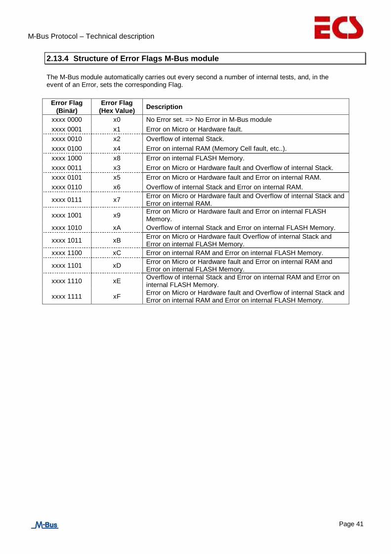
2.13.4 Structure of Error Flags M-Bus module
The M-Bus module automatically carries out every second a number of internal tests, and, in the event of an Error, sets the corresponding Flag.
Error Flag
(Binär)
Error Flag
(Hex Value) Description
xxxx 0000 x0 No Error set. => No Error in M-Bus module
xxxx 0001 x1 Error on Micro or Hardware fault.
xxxx 0010 x2 Overflow of internal Stack.
xxxx 0100 x4 Error on internal RAM (Memory Cell fault, etc..).
xxxx 1000 x8 Error on internal FLASH Memory.
xxxx 0011 x3 Error on Micro or Hardware fault and Overflow of internal Stack.
xxxx 0101 x5 Error on Micro or Hardware fault and Error on internal RAM.
xxxx 0110 x6 Overflow of internal Stack and Error on internal RAM.
xxxx 0111 x7 Error on Micro or Hardware fault and Overflow of internal Stack and Error on internal RAM.
xxxx 1001 x9 Error on Micro or Hardware fault and Error on internal FLASH Memory.
xxxx 1010 xA Overflow of internal Stack and Error on internal FLASH Memory.
xxxx 1011 xB Error on Micro or Hardware fault Overflow of internal Stack and Error on internal FLASH Memory.
xxxx 1100 xC Error on internal RAM and Error on internal FLASH Memory.
xxxx 1101 xD Error on Micro or Hardware fault and Error on internal RAM and Error on internal FLASH Memory.
xxxx 1110 xE Overflow of internal Stack and Error on internal RAM and Error on internal FLASH Memory.
xxxx 1111 xF Error on Micro or Hardware fault and Overflow of internal Stack and Error on internal RAM and Error on internal FLASH Memory.
M-Bus Protocol – Technical description
Page 42
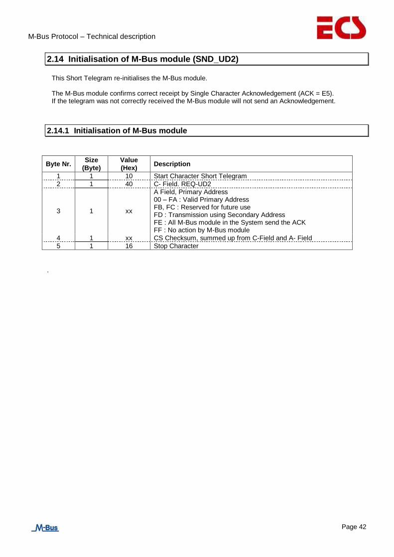
2.14 Initialisation of M-Bus module (SND_UD2)
This Short Telegram re-initialises the M-Bus module.
The M-Bus module confirms correct receipt by Single Character Acknowledgement (ACK = E5). If the telegram was not correctly received the M-Bus module will not send an Acknowledgement.
2.14.1 Initialisation of M-Bus module
Byte Nr. Size
(Byte)
Value
(Hex) Description
1 1 10 Start Character Short Telegram
2 1 40 C- Field. REQ-UD2
3 1 xx
A Field, Primary Address 00 – FA : Valid Primary Address FB, FC : Reserved for future use FD : Transmission using Secondary Address FE : All M-Bus module in the System send the ACK FF : No action by M-Bus module
4 1 xx CS Checksum, summed up from C-Field and A- Field
5 1 16 Stop Character
.