m-bus protocol calec energy master
TRANSCRIPT

VD 3-138 e 02.2011
M-Bus protocol CALEC® energy master Manufacturer: Aquametro AG Device: CALEC® energy master Firmware version: 1.03.XX or higher Manufacturer code: 05B4h Device version: D0 (inactive), D1(Flow), D2 (Standard),
D3 (BDE), D4 (BDV), D5 (TWIN V), D7 (saturated steam), D8 (steam)
2 M-Bus protocol CALEC® energy master
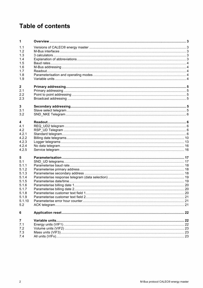
Table of contents
1 Overview ................................................................................................................................................ 3
1.1 Versions of CALEC® energy master ...................................................................................................... 31.2 M-Bus interfaces ..................................................................................................................................... 31.3 3 calculators ............................................................................................................................................ 31.4 Explanation of abbreviations ................................................................................................................... 31.5 Baud rates ............................................................................................................................................... 41.6 M-Bus addressing ................................................................................................................................... 41.7 Readout ................................................................................................................................................... 41.8 Parameterisation and operating modes .................................................................................................. 41.9 Variable units .......................................................................................................................................... 4 2 Primary addressing ............................................................................................................................... 52.1 Primary addressing ................................................................................................................................. 52.2 Point to point addressing ........................................................................................................................ 52.3 Broadcast addressing ............................................................................................................................. 5 3 Secondary addressing .......................................................................................................................... 53.1 Slave select telegram .............................................................................................................................. 53.2 SND_NKE Telegram ............................................................................................................................... 6 4 Readout .................................................................................................................................................. 64.1 REQ_UD2 telegram ................................................................................................................................ 64.2 RSP_UD Telegram ................................................................................................................................. 64.2.1 Standard telegram ................................................................................................................................... 64.2.2 Billing date telegrams ............................................................................................................................ 104.2.3 Logger telegrams .................................................................................................................................. 134.2.4 No data telegram ................................................................................................................................... 164.2.5 Service telegram ................................................................................................................................... 16 5 Parameterisation ................................................................................................................................. 175.1 SND_UD telegrams ............................................................................................................................... 175.1.1 Parameterise baud rate ......................................................................................................................... 185.1.2 Parameterise primary address .............................................................................................................. 185.1.3 Parameterise secondary address ......................................................................................................... 185.1.4 Parameterise response telegram (data selection) ................................................................................ 195.1.5 Parameterise date/time ......................................................................................................................... 195.1.6 Parameterise billing date 1 .................................................................................................................... 205.1.7 Parameterise billing date 2 .................................................................................................................... 205.1.8 Parameterise customer text field 1 ........................................................................................................ 205.1.9 Parameterise customer text field 2 ........................................................................................................ 215.1.10 Parameterise error hour counter ........................................................................................................... 215.2 ACK telegram ........................................................................................................................................ 21 6 Application reset ................................................................................................................................. 22 7 Variable units ....................................................................................................................................... 227.1 Energy units (VIF1) ............................................................................................................................... 227.2 Volume units (VIF2) .............................................................................................................................. 237.3 Mass units (VIF3) .................................................................................................................................. 237.4 All units (VIFx) ....................................................................................................................................... 23

M-Bus protocol CALEC® energy master 3
1 Overview 1.1 Versions of CALEC® energy master There are various versions of the CALEC® energy master This document describes the M-Bus protocol for all versions.
Version Device version (DEV):
Explanation
Standard D2 Water heat carrier (fluid as option) BDE D3 Bidirectional energy measurement, temperature controlled BDV D4 Bidirectional energy measurement, volume controlled TWIN-V D5 For composite or dual volume transmitters Flow D1 Flow calculator Inactive D0 Inactive Saturated steam
D7 Saturated steam
Steam D8 Steam
1.2 M-Bus interfaces The CALEC® energy master has up to 4 independent M-Bus interfaces. Infrared in accordance with IEC870-5 and IrDA are always available. There is also the option of fitting an additional two M-Bus modules. The interfaces are independent of one another and can be operated at the same time. The baud rates and reply telegrams can also be configured independently of one another.
1.3 3 calculators The CALEC® energy master has up to 3 calculators. On the M-Bus, the device reacts in the same way as 3 independent counters. Each counter (calculator) has its own primary and secondary address. If the device is addressed via point to point address 254, only calculator 1 reacts.
1.4 Explanation of abbreviations
Abbreviation Explanation REQ_UD2 Request for an RSP_UD telegram RSP_UD Data telegram from the CALEC SND_UD Data telegram to the CALEC SND_NKE Initialisation telegram in accordance with EN 13757 ACK Confirmation telegram in accordance with EN 13757 PADR Place-holder for the primary address (1 byte) LEN Place-holder for the length byte (1 byte), calculated in accordance with EN 13757 IDENT Place-holder for the secondary address (4 bytes) MAN Place-holder for the manufacturer code (2 bytes) DEV Place-holder for the device version (1 byte) MED Place-holder for the medium (1 byte) ACC Place-holder for the access counter (1 byte) STAT Place-holder for the status (1 byte) CS Place-holder for the checksum (1 byte), calculated in accordance with EN 13757

4 M-Bus protocol CALEC® energy master
1.5 Baud rates The CALEC® energy master can communicate at 300, 2400 and 9600 baud. For IrDA, the baud rate is 57.6 kbaud, which is configured automatically. If using a virtual COM port such as IrCOMM2k, the baud rate setting in the application software is ignored. The factory setting for the baud rate is 2400.
1.6 M-Bus addressing The device supports primary and secondary addressing in accordance with EN 13757. Addressing PADR For details see chapter Primary addressing 0 250 (Default: 0) 2.1 Primary addressing Point to point addressing 254 2.2 Point to point addressing Broadcast addressing 255 2.3 Broadcast addressing Secondary addressing 253 3 Secondary addressing
1.7 Readout The CALEC® energy master recognises 5 different kinds of reply telegrams. The factory setting for the device is an active standard telegram. Reply telegram Quantity Content For details see chapter Standard 1 Current meter readings 4.2.1 Standard telegram Billing date 2 Billing date data 4.2.2 Billing date telegram Logger 100 Logger data 4.2.2 Billing date telegram No data 1 No data available 4.2.4 No data telegram Service 1 for service purposes 4.2.5 Service telegram
1.8 Parameterisation and operating modes There are 3 coded operating modes which allow access to different parameters. Mode Operating
mode
User Standard Locked padlock symbol on the display The keys cannot be used to change parameters. Only non-counter-related parameters, can be changed via M-Bus
Service Medium Open padlock symbol on the display The keys or M-Bus can only be used to amend parameters which are not subject to metrological verification.
Program Low No padlock symbol on the display The keys or M-Bus can be used to amend all parameters. Changing the protection type to programming may involve destroying the verification seal.
Parameter Protection type For details see chapter Baud rate User 5.1.1 Parameterise baud rate Primary address User 5.1.2 Parameterise primary address Secondary address User 5.1.3 Parameterise secondary address Reply telegram User 5.1.4 Parameterise response telegram Date/Time User 5.1.5 Parameterise date/time Billing date 1, 2 User 5.1.6/7 Parameterise billing date 1 Customer text field 1 User 5.1.8 Parameterise customer text field 1 Customer text field 2 User 5.1.8 Parameterise customer text field 1 Error hours counter Programming mode 5.1.9 Error hours counter
1.9 Variable units The units and resolutions of the meter readings and pulse values of the CALEC® energy master can be parameterised in any way. This has a direct impact on the transfer of data to the M-Bus in the form of different VIF.

M-Bus protocol CALEC® energy master 5
2 Primary addressing 2.1 Primary addressing Individual CALEC® energy masters can be addressed via primary addressing in an M-Bus network. The primary address range allowed is 0...250. Each telegram contains the primary address in the A field.
2.2 Point to point addressing If the M-Bus network consists of a single CALEC® energy master, point to point addressing can be used. To do this, the A field in the Master telegram is set to 254 (FEh). The CALEC® energy master responds to point to point telegrams irrespective of how the primary address is parameterised. If multiple calculators are active, then only calculator 1 will respond.
2.3 Broadcast addressing If all the meters in a network are to receive a telegram (e.g. setting the date) and process it at the same time, broadcast addressing can be used. The A field in the telegram of the Master is set to 255 (FFh). The CALEC® energy master does not respond to broadcast telegrams, but executes the commands. It makes no difference how the primary address is parameterised. If multiple calculators are active, the command is executed by all of them.
3 Secondary addressing If an M-Bus network contains more then 250 meters, secondary addressing is used. Secondary addressing uses the A field: 253 (FDh) with the 8-byte header selected. Secondary addressing must be set up before the actual communication with the CALEC® energy master using a slave select telegram. Secondary addressing needs to be removed again after the actual communication.
3.1 Slave select telegram The CALEC® energy master can be selected for secondary addressing using the following telegram: Name Number of
bytes Value Explanation / example
Start 1 68h L field 1 0Bh L field 1 0Bh Start 1 68h C field 1 53h / 73h SND_UD A field 1 FEh Secondary addressing CI field 1 52h Slave select Secondary add. 4 IDENT Secondary address Manufacturer code
2 MAN 05B4h = Aquametro
Device version 1 DEV D2h = Standard energy Medium 1 MED 04h = return / 0Ch = flow Checksum 1 CS Stop 1 16h C field: The CALEC® energy master does not distinguish between 53h and 73h. IDENT: The 4-bit wildcard Fh can also be used instead of the exact secondary address. Example
FFFFF344h: It selects all devices whose secondary address ends with 344h. MAN: The 16-bit wildcard FFFFh can also be used instead of the 05B4h. DEV The 8-bit wildcard FFh can be used instead of, for example, D2h. MED: The 8-bit wildcard FFh can be used instead of, for example, 04h. • If all 4 details tally with the parameterisation of the device, it is selected and responds with an ACK telegram. • If at least one of the details does not match the parameterisation of the device, it is deselected and does not respond.
6 M-Bus protocol CALEC® energy master
3.2 SND_NKE Telegram Secondary addressing can be cleared with the following telegram: Name Number of
bytes Value Explanation
Start 1 10h C field 1 40h SND_NKE A field 1 FEh Checksum 1 CS Stop 1 16
• The CALEC® energy master responds with an ACK telegram.
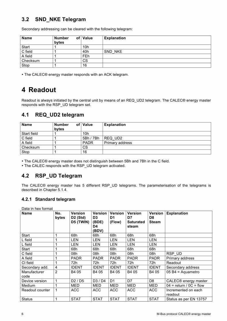
4 Readout Readout is always initiated by the central unit by means of an REQ_UD2 telegram. The CALEC® energy master responds with the RSP_UD telegram set.
4.1 REQ_UD2 telegram
Name Number of bytes
Value Explanation
Start field 1 10h C field 1 5Bh / 7Bh REQ_UD2 A field 1 PADR Primary address Checksum 1 CS Stop 1 16 • The CALEC® energy master does not distinguish between 5Bh and 7Bh in the C field. • The CALEC responds with the RSP_UD telegram activated.
4.2 RSP_UD Telegram The CALEC® energy master has 5 different RSP_UD telegrams. The parameterisation of the telegrams is described in Chapter 5.1.4.
4.2.1 Standard telegram
Data in hex format Name No.
bytes Version D2 (Std) D5 (TWIN)
Version D3 (BDE) D4 (BDV)
Version D1 (Flow)
Version D7 Saturated steam
Version D8 Steam
Explanation
Start 1 68h 68h 68h 68h 68h L field 1 LEN LEN LEN LEN LEN L field 1 LEN LEN LEN LEN LEN Start 1 68h 68h 68h 68h 68h C field 1 08h 08h 08h 08h 08h RSP_UD A field 1 PADR PADR PADR PADR PADR Primary address CI field 1 72h 72h 72h 72h 72h Readout Secondary add. 4 IDENT IDENT IDENT IDENT IDENT Secondary address Manufacturer code
2 B4 05 B4 05 B4 05 B4 05 B4 05 05 B4 = Aquametro
Device version 1 D2 / D5 D3 / D4 D1 D7 D8 CALEC® energy master Medium 1 MED MED MED MED MED 04 = return / 0C = flow Readout counter 1 ACC ACC ACC ACC ACC Incremented on each
readout Status 1 STAT STAT STAT STAT STAT Status as per EN 13757
M-Bus protocol CALEC® energy master 7
Name No. bytes
Version D2 (Std) D5 (TWIN)
Version D3 (BDE) D4 (BDV)
Version D1 (Flow)
Version D7 Saturated steam
Version D8 Steam
Explanation
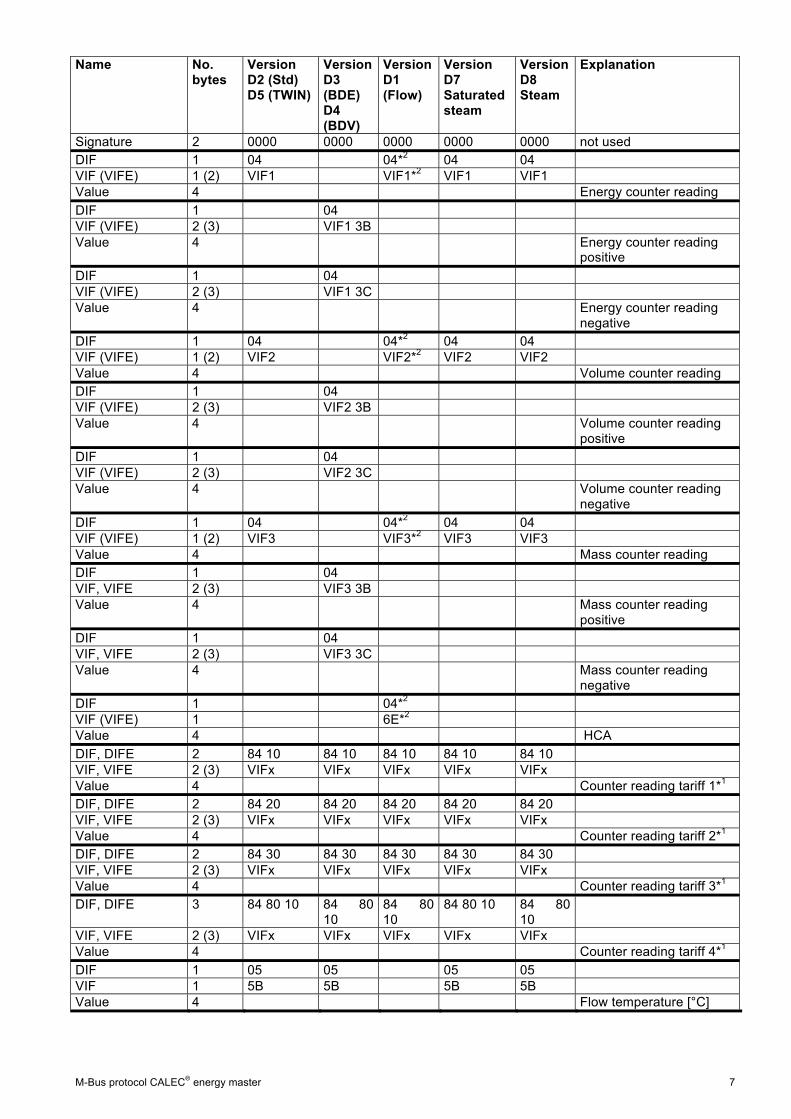
Signature 2 0000 0000 0000 0000 0000 not used DIF 1 04 04*2 04 04 VIF (VIFE) 1 (2) VIF1 VIF1*2 VIF1 VIF1 Value 4 Energy counter reading DIF 1 04 VIF (VIFE) 2 (3) VIF1 3B Value 4 Energy counter reading
positive DIF 1 04 VIF (VIFE) 2 (3) VIF1 3C Value 4 Energy counter reading
negative DIF 1 04 04*2 04 04 VIF (VIFE) 1 (2) VIF2 VIF2*2 VIF2 VIF2 Value 4 Volume counter reading DIF 1 04 VIF (VIFE) 2 (3) VIF2 3B Value 4 Volume counter reading
positive DIF 1 04 VIF (VIFE) 2 (3) VIF2 3C Value 4 Volume counter reading
negative DIF 1 04 04*2 04 04 VIF (VIFE) 1 (2) VIF3 VIF3*2 VIF3 VIF3 Value 4 Mass counter reading DIF 1 04 VIF, VIFE 2 (3) VIF3 3B Value 4 Mass counter reading
positive DIF 1 04 VIF, VIFE 2 (3) VIF3 3C Value 4 Mass counter reading
negative DIF 1 04*2 VIF (VIFE) 1 6E*2 Value 4 HCA DIF, DIFE 2 84 10 84 10 84 10 84 10 84 10 VIF, VIFE 2 (3) VIFx VIFx VIFx VIFx VIFx Value 4 Counter reading tariff 1*1 DIF, DIFE 2 84 20 84 20 84 20 84 20 84 20 VIF, VIFE 2 (3) VIFx VIFx VIFx VIFx VIFx Value 4 Counter reading tariff 2*1 DIF, DIFE 2 84 30 84 30 84 30 84 30 84 30 VIF, VIFE 2 (3) VIFx VIFx VIFx VIFx VIFx Value 4 Counter reading tariff 3*1 DIF, DIFE 3 84 80 10 84 80
10 84 80 10
84 80 10 84 80 10
VIF, VIFE 2 (3) VIFx VIFx VIFx VIFx VIFx Value 4 Counter reading tariff 4*1 DIF 1 05 05 05 05 VIF 1 5B 5B 5B 5B Value 4 Flow temperature [°C]

8 M-Bus protocol CALEC® energy master
Name No. bytes
Version D2 (Std) D5 (TWIN)
Version D3 (BDE) D4 (BDV)
Version D1 (Flow)
Version D7 Saturated steam
Version D8 Steam
Explanation
DIF 1 05 05 05 05 D7/D8: closed circuit only VIF 1 5F 5F 5F 5F Value 4 Return temperature [°C] DIF 1 05 05 05 05 D7/D8: closed circuit only VIF 1 63 63 63 63 Value 4 differential Temperature
[K] DIF 1 05 05 05*2 05 05 VIF 1 2B 2B 2B*2 2B 2B Value 4 Power [W] DIF, DIFE 2 85 40 85 40 85 40 Option: Chiller VIF, VIFE 2 AB 3A AB 3A AB 3A Value 4 Power [RT] DIF,DIFE1,DIFE2 3 85 80 40 85 80
40 85 80 40
Option: Chiller
VIF,VIFE1,DIFE2 3 AB B2 3A AB B2 3A
AB B2 3A
Value 4 Efficiency [RT/kW] DIF 1 05 05 05*2 05 05 VIF 1 3B 3B 3B*2 3B 3B Value 4 Flow [l/h] DIF 1 05 05 05*2 05 05 VIF 1 53 53 53*2 53 53 Value 4 Mass flow [kg/h] DIF 1 05 05 VIF 1 6B 6B Value 4 Pressure [bar] DIF 1 05 05 05 05 VIF, VIFE 2 9B 2C 9B 2C 9B 2C 9B 2C Value 4 Density [kg / l] DIF 1 05 05 VIF, VIFE 2 83 33 83 33 Value 4 k-factor [Wh / K / l ] DIF 1 05 05 05 05 D7/D8: closed circuit only VIF, VIFE 2 83 2E 83 2E 83 2E 83 2E Value 4 differential Enthalpy
[Wh/kg] DIF 2 85 40 85 40 VIF, VIFE 2 83 2E 83 2E Value 4 Enthalpy flow [Wh/kg] DIF 3 85 80 40 85 80
40 D7/D8: closed circuit only
VIF, VIFE 2 83 2E 83 2E Value 4 Enthalpy return [Wh/kg] DIF 1 05*2 VIF (VIFE) 2 EE 20*2 Value 4 Frequency [Hz] DIF 1 04 04 04 04 04 VIF 1 22 22 22 22 22 Value 4 Operating hours [h] DIF 1 34 34 34 34 34 VIF 1 22 22 22 22 22 Value 4 Error hours [h]
M-Bus protocol CALEC® energy master 9
Name No. bytes
Version D2 (Std) D5 (TWIN)
Version D3 (BDE) D4 (BDV)
Version D1 (Flow)
Version D7 Saturated steam
Version D8 Steam
Explanation
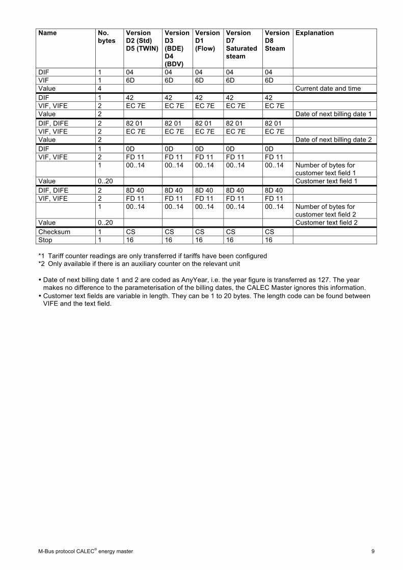
DIF 1 04 04 04 04 04 VIF 1 6D 6D 6D 6D 6D Value 4 Current date and time DIF 1 42 42 42 42 42 VIF, VIFE 2 EC 7E EC 7E EC 7E EC 7E EC 7E Value 2 Date of next billing date 1 DIF, DIFE 2 82 01 82 01 82 01 82 01 82 01 VIF, VIFE 2 EC 7E EC 7E EC 7E EC 7E EC 7E Value 2 Date of next billing date 2 DIF 1 0D 0D 0D 0D 0D VIF, VIFE 2 FD 11 FD 11 FD 11 FD 11 FD 11 1 00..14 00..14 00..14 00..14 00..14 Number of bytes for
customer text field 1 Value 0..20 Customer text field 1 DIF, DIFE 2 8D 40 8D 40 8D 40 8D 40 8D 40 VIF, VIFE 2 FD 11 FD 11 FD 11 FD 11 FD 11 1 00..14 00..14 00..14 00..14 00..14 Number of bytes for
customer text field 2 Value 0..20 Customer text field 2 Checksum 1 CS CS CS CS CS Stop 1 16 16 16 16 16 *1 Tariff counter readings are only transferred if tariffs have been configured *2 Only available if there is an auxiliary counter on the relevant unit • Date of next billing date 1 and 2 are coded as AnyYear, i.e. the year figure is transferred as 127. The year makes no difference to the parameterisation of the billing dates, the CALEC Master ignores this information. • Customer text fields are variable in length. They can be 1 to 20 bytes. The length code can be found between VIFE and the text field.
10 M-Bus protocol CALEC® energy master
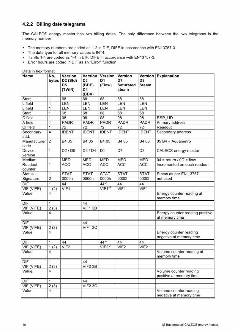
4.2.2 Billing date telegrams
The CALEC® energy master has two billing dates. The only difference between the two telegrams is the memory number • The memory numbers are coded as 1-2 in DIF, DIFE in accordance with EN13757-3. • The data type for all memory values is INT4. • Tariffs 1-4 are coded as 1-4 in DIF, DIFE in accordance with EN13757-3. • Error hours are coded in DIF as an "Error" function.
Data in hex format Name No.
bytes Version D2 (Std) D5 (TWIN)
Version D3 (BDE) D4 (BDV)
Version D1 (Flow)
Version D7 Saturated steam
Version D8 Steam
Explanation
Start 1 68 68 68 68 68 L field 1 LEN LEN LEN LEN LEN L field 1 LEN LEN LEN LEN LEN Start 1 68 68 68 68 68 C field 1 08 08 08 08 08 RSP_UD A field 1 PADR PADR PADR PADR PADR Primary address CI field 1 72 72 72 72 72 Readout Secondary add.
4 IDENT IDENT IDENT IDENT IDENT Secondary address
Manufacturer code
2 B4 05 B4 05 B4 05 B4 05 B4 05 05 B4 = Aquametro
Device version
1 D2 / D5 D3 / D4 D1 D7 D8 CALEC® energy master
Medium 1 MED MED MED MED MED 04 = return / 0C = flow Readout counter
1 ACC ACC ACC ACC ACC Incremented on each readout
Status 1 STAT STAT STAT STAT STAT Status as per EN 13757 Signature 2 0000h 0000h 0000h 0000h 0000h not used DIF 1 44 44*2 44 44 VIF (VIFE) 1 (2) VIF1 VIF1*2 VIF1 VIF1 Value 4 Energy counter reading at
memory time DIF 1 44 VIF (VIFE) 2 (3) VIF1 3B Value 4 Energy counter reading positive
at memory time DIF 1 44 VIF (VIFE) 2 (3) VIF1 3C Value 4 Energy counter reading
negative at memory time DIF 1 44 44*2 44 44 VIF (VIFE) 1 (2) VIF2 VIF2*2 VIF2 VIF2 Value 4 Volume counter reading at
memory time DIF 1 44 VIF (VIFE) 2 (3) VIF2 3B Value 4 Volume counter reading
positive at memory time DIF 1 44 VIF (VIFE) 2 (3) VIF2 3C Value 4 Volume counter reading
negative at memory time
M-Bus protocol CALEC® energy master 11
Name No. bytes
Version D2 (Std) D5 (TWIN)
Version D3 (BDE) D4 (BDV)
Version D1 (Flow)
Version D7 Saturated steam
Version D8 Steam
Explanation
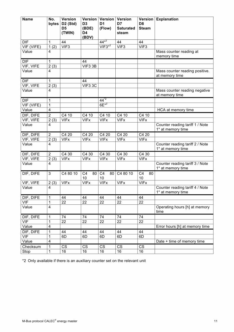
DIF 1 44 44*2 44 44 VIF (VIFE) 1 (2) VIF3 VIF3*2 VIF3 VIF3 Value 4 Mass counter reading at
memory time DIF 1 44 VIF, VIFE 2 (3) VIF3 3B Value 4 Mass counter reading positive.
at memory time DIF 1 44 VIF, VIFE 2 (3) VIF3 3C Value 4 Mass counter reading negative
at memory time DIF 1 44*2 VIF (VIFE) 1 6E*2 Value 4 HCA at memory time DIF, DIFE 2 C4 10 C4 10 C4 10 C4 10 C4 10 VIF, VIFE 2 (3) VIFx VIFx VIFx VIFx VIFx Value 4 Counter reading tariff 1 / Note
1* at memory time DIF, DIFE 2 C4 20 C4 20 C4 20 C4 20 C4 20 VIF, VIFE 2 (3) VIFx VIFx VIFx VIFx VIFx Value 4 Counter reading tariff 2 / Note
1* at memory time DIF, DIFE 2 C4 30 C4 30 C4 30 C4 30 C4 30 VIF, VIFE 2 (3) VIFx VIFx VIFx VIFx VIFx Value 4 Counter reading tariff 3 / Note
1* at memory time DIF, DIFE 3 C4 80 10 C4 80
10 C4 80 10
C4 80 10 C4 80 10
VIF, VIFE 2 (3) VIFx VIFx VIFx VIFx VIFx Value 4 Counter reading tariff 4 / Note
1* at memory time DIF, DIFE 1 44 44 44 44 44 VIF 1 22 22 22 22 22 Value 4 Operating hours [h] at memory
time DIF, DIFE 1 74 74 74 74 74 VIF 1 22 22 22 22 22 Value 4 Error hours [h] at memory time DIF, DIFE 1 44 44 44 44 44 VIF 1 6D 6D 6D 6D 6D Value 4 Date + time of memory time Checksum 1 CS CS CS CS CS Stop 1 16 16 16 16 16 *2 Only available if there is an auxiliary counter set on the relevant unit

12 M-Bus protocol CALEC® energy master
Name No.
bytes Version D2 (Std) D5 (TWIN)
Version D3 (BDE) D4 (BDV)
Version D1 (Flow)
Version D7 Saturated steam
Version D8 Steam
Explanation
Start 1 68 68 68 68 68 L field 1 LEN LEN LEN LEN LEN L field 1 LEN LEN LEN LEN LEN Start 1 68 68 68 68 68 C field 1 08 08 08 08 08 RSP_UD A field 1 PADR PADR PADR PADR PADR Primary address CI field 1 72 72 72 72 72 Readout Secondary add.
4 IDENT IDENT IDENT IDENT IDENT Secondary address
Manufacturer code
2 B4 05 B4 05 B4 05 B4 05 B4 05 05 B4 = Aquametro
Device version
1 D2 / D5 D3 / D4 D1 D7 D8 CALEC® energy master
Medium 1 MED MED MED MED MED 04 = return / 0C = flow Readout counter
1 ACC ACC ACC ACC ACC Incremented on each readout
Status 1 STAT STAT STAT STAT STAT Status as per EN 13757 Signature 2 0000 0000 0000 0000 0000 not used DIF 2 84 01 84 01*2 84 01 84 01 VIF (VIFE) 1 (2) VIF1 VIF1*2 VIF1 VIF1 Value 4 Energy counter reading at
memory time DIF 2 84 01 VIF (VIFE) 2 (3) VIF1 3B Value 4 Energy counter reading positive
at memory time DIF 2 84 01 VIF (VIFE) 2 (3) VIF1 3C Value 4 Energy counter reading
negative at memory time DIF 2 84 01 84 01*2 84 01 84 01 VIF (VIFE) 1 (2) VIF2 VIF2*2 VIF2 VIF2 Value 4 Volume counter reading at
memory time DIF 2 84 01 VIF (VIFE) 2 (3) VIF2 3B Value 4 Volume counter reading
positive at memory time DIF 2 84 01 VIF (VIFE) 2 (3) VIF2 3C Value 4 Volume counter reading
negative at memory time DIF 2 84 01 84 01*2 84 01 84 01 VIF (VIFE) 1 (2) VIF3 VIF3*2 VIF3 VIF3 Value 4 Mass counter reading at
memory time DIF 2 84 01 VIF, VIFE 2 (3) VIF3 3B Value 4 Mass counter reading positive
at memory time DIF 2 84 01 VIF, VIFE 2 (3) VIF3 3C Value 4 Mass counter reading negative
at memory time
M-Bus protocol CALEC® energy master 13
Name No. bytes
Version D2 (Std) D5 (TWIN)
Version D3 (BDE) D4 (BDV)
Version D1 (Flow)
Version D7 Saturated steam
Version D8 Steam
Explanation
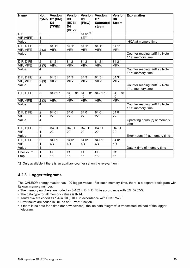
DIF 2 84 01*2 VIF (VIFE) 1 6E*2 Value 4 HCA at memory time DIF, DIFE 2 84 11 84 11 84 11 84 11 84 11 VIF, VIFE 2 (3) VIFx VIFx VIFx VIFx VIFx Value 4 Counter reading tariff 1 / Note
1* at memory time DIF, DIFE 2 84 21 84 21 84 21 84 21 84 21 VIF, VIFE 2 (3) VIFx VIFx VIFx VIFx VIFx Value 4 Counter reading tariff 2 / Note
1* at memory time DIF, DIFE 2 84 31 84 31 84 31 84 31 84 31 VIF, VIFE 2 (3) VIFx VIFx VIFx VIFx VIFx Value 4 Counter reading tariff 3 / Note
1* at memory time DIF, DIFE 3 84 81 10 84 81
10 84 81 10
84 81 10 84 81 10
VIF, VIFE 2 (3) VIFx VIFx VIFx VIFx VIFx Value 4 Counter reading tariff 4 / Note
1* at memory time DIF, DIFE 2 84 01 84 01 84 01 84 01 84 01 VIF 1 22 22 22 22 22 Value 4 Operating hours [h] at memory
time DIF, DIFE 2 B4 01 B4 01 B4 01 B4 01 B4 01 VIF 1 22 22 22 22 22 Value 4 Error hours [h] at memory time DIF, DIFE 2 84 01 84 01 84 01 84 01 84 01 VIF 1 6D 6D 6D 6D 6D Value 4 Date + time of memory time Checksum 1 CS CS CS CS CS Stop 1 16 16 16 16 16 *2 Only available if there is an auxiliary counter set on the relevant unit
4.2.3 Logger telegrams
The CALEC® energy master has 100 logger values. For each memory time, there is a separate telegram with its own memory number. • The memory numbers are coded as 3-102 in DIF, DIFE in accordance with EN13757-3. • The data type for all memory values is INT4. • Tariffs 1-4 are coded as 1-4 in DIF, DIFE in accordance with EN13757-3. • Error hours are coded in DIF as an "Error" function. • If there is no date for a time (for new devices), the 'no data telegram' is transmitted instead of the logger telegram.

14 M-Bus protocol CALEC® energy master
Name No. bytes
Version D2 (Std) D5 (TWIN)
Version D3 (BDE) D4 (BDV)
Version D1 (Flow)
Version D7 Saturated steam
Version D8 Steam
Explanation
Start 1 68h 68h 68h 68h 68h L field 1 LEN LEN LEN LEN LEN L field 1 LEN LEN LEN LEN LEN Start 1 68h 68h 68h 68h 68h C field 1 08h 08h 08h 08h 08h RSP_UD A field 1 PADR PADR PADR PADR PADR Primary address CI field 1 72h 72h 72h 72h 72h Readout Secondary add.
4 IDENT IDENT IDENT IDENT IDENT Secondary address
Manufacturer code
2 B4 05 B4 05 B4 05 B4 05 B4 05 05 B4 = Aquametro
Device version
1 D2 / D5 D3 / D4 D1 D7 D8 CALEC® energy master
Medium 1 MED MED MED MED MED 04 = return / 0C = flow Readout counter
1 ACC ACC ACC ACC ACC Incremented on each readout
Status 1 STAT STAT STAT STAT STAT Status as per EN 13757 Signature 2 0000h 0000h 0000h 0000h 0000h not used DIF VIF (VIFE) 1 (2) VIF1 VIF1*2 VIF1 VIF1 Value 4 Energy counter reading at
memory time DIF VIF (VIFE) 2 (3) VIF1 3B Value 4 Energy counter reading positive
at memory time DIF VIF (VIFE) 2 (3) VIF1 3C Value 4 Energy counter reading
negative at memory time DIF VIF (VIFE) 1 (2) VIF2 VIF*2 VIF2 VIF2 Value 4 Volume counter reading at
memory time DIF VIF (VIFE) 2 (3) VIF2 3B Value 4 Volume counter reading
positive at memory time DIF VIF (VIFE) 2 (3) VIF2 3C Value 4 Volume counter reading
negative at memory time DIF VIF (VIFE) 1 (2) VIF3 VIF3*2 VIF3 VIF3 Value 4 Mass counter reading at
memory time DIF VIF, VIFE 2 (3) VIF3 3B Value 4 Mass counter reading positive
at memory time DIF VIF, VIFE 2 (3) VIF3 3C Value 4 Mass counter reading negative
at memory time

M-Bus protocol CALEC® energy master 15
Name No. bytes
Version D2 (Std) D5 (TWIN)
Version D3 (BDE) D4 (BDV)
Version D1 (Flow)
Version D7 Saturated steam
Version D8 Steam
Explanation
DIF VIF (VIFE) 1 6E*2 Value 4 HCA at memory time DIF, DIFE VIF, VIFE 2 (3) VIFx VIFx VIFx VIFx VIFx Value 4 Counter reading tariff 1 / Note
1* at memory time DIF, DIFE VIF, VIFE 2 (3) VIFx VIFx VIFx VIFx VIFx Value 4 Counter reading tariff 2 / Note
1* at memory time DIF, DIFE VIF, VIFE 2 (3) VIFx VIFx VIFx VIFx VIFx Value 4 Counter reading tariff 3 / Note
1* at memory time DIF, DIFE VIF, VIFE 2 (3) VIFx VIFx VIFx VIFx VIFx Value 4 Counter reading tariff 4 / Note
1* at memory time DIF, DIFE VIF 1 22 22 22 22 22 Value 4 Operating hours [h] at memory
time DIF, DIFE VIF 1 22 22 22 22 22 Value 4 Error hours [h] at memory time DIF, DIFE VIF 1 6D 6D 6D 6D 6D Value 4 Date + time of memory time DIF, DIFE VIF 1 2B 2B 2B*2 2B 2B Value 4 max. power in logger period [W] DIF, DIFE VIF, VIFE 2 AB 39 AB 39 AB 39*2 AB 39 AB 39 Value 4 Time of max. power DIF, DIFE VIF 1 3B 3B*2 3B 3B Value 4 max. flow [l/h] for logger period DIF, DIFE VIF, VIFE 2 BB 39 BB 39 BB 39 BB 39 BB 39 Value 4 Time of maximum flow DIF, DIFE VIF 1 53 53*2 Value 4 max. mass flow [kg/h] for logger
period DIF, DIFE VIF, VIFE 2 D3 39 D3 39 D3 39 D3 39 D3 39 Value 4 Time of maximum mass flow DIF, DIFE VIF 1 5B 5B 5B 5B Value 4 Maximum flow temperature [°C]
for logger period DIF, DIFE VIF, VIFE 2 DB 39 DB 39 DB 39 DB 39 Value 4 Time of maximum flow
temperature
16 M-Bus protocol CALEC® energy master
Name No. bytes
Version D2 (Std) D5 (TWIN)
Version D3 (BDE) D4 (BDV)
Version D1 (Flow)
Version D7 Saturated steam
Version D8 Steam
Explanation
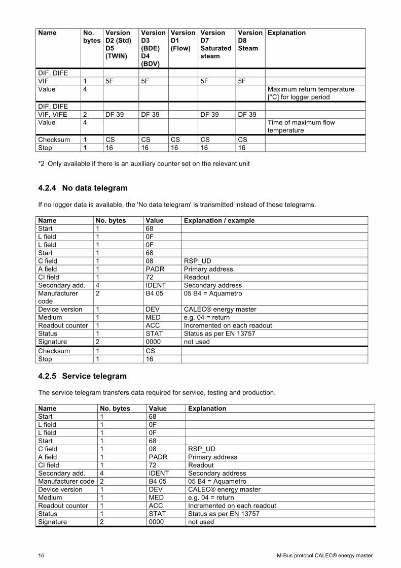
DIF, DIFE VIF 1 5F 5F 5F 5F Value 4 Maximum return temperature
[°C] for logger period DIF, DIFE VIF, VIFE 2 DF 39 DF 39 DF 39 DF 39 Value 4 Time of maximum flow
temperature Checksum 1 CS CS CS CS CS Stop 1 16 16 16 16 16 *2 Only available if there is an auxiliary counter set on the relevant unit
4.2.4 No data telegram
If no logger data is available, the 'No data telegram' is transmitted instead of these telegrams. Name No. bytes Value Explanation / example Start 1 68 L field 1 0F L field 1 0F Start 1 68 C field 1 08 RSP_UD A field 1 PADR Primary address CI field 1 72 Readout Secondary add. 4 IDENT Secondary address Manufacturer code
2 B4 05 05 B4 = Aquametro
Device version 1 DEV CALEC® energy master Medium 1 MED e.g. 04 = return Readout counter 1 ACC Incremented on each readout Status 1 STAT Status as per EN 13757 Signature 2 0000 not used Checksum 1 CS Stop 1 16
4.2.5 Service telegram
The service telegram transfers data required for service, testing and production. Name No. bytes Value Explanation Start 1 68 L field 1 0F L field 1 0F Start 1 68 C field 1 08 RSP_UD A field 1 PADR Primary address CI field 1 72 Readout Secondary add. 4 IDENT Secondary address Manufacturer code 2 B4 05 05 B4 = Aquametro Device version 1 DEV CALEC® energy master Medium 1 MED e.g. 04 = return Readout counter 1 ACC Incremented on each readout Status 1 STAT Status as per EN 13757 Signature 2 0000 not used

M-Bus protocol CALEC® energy master 17
Name No. bytes Value Explanation DIF, DIVE 2 85 40 VIF, VIFE 2 DB 3A Value 4 Mean PT100 input 1 DIF, DIVE 3 85 80 40 VIF, VIFE 2 DB 3A Value 4 Standard deviation PT100 input 1 DIF, DIVE 2 85 40 VIF, VIFE 2 DF 3A Value 4 Mean PT100 input 2 DIF, DIVE 3 85 80 40 VIF, VIFE 2 DF 3A Value 4 Standard deviation PT100 input 2 DIF 1 01 VIF 1 7A Value 1 Primary address DIF 1 0C VIF 1 79 Value 4 Secondary address DIF 1 0C VIF 1 78 Value 4 Production number DIF 2 8C 40 VIF 1 78 Value 4 Print number DIF 1 02 VIF, VIFE 2 EC 39 Value 2 Production date DIF 1 04 VIF, VIFE 2 FD 66 Value 4 Validation time DIF, DIFE 2 84 40 VIF, VIFE 2 FD 66 Value 4 Validation time invalid DIF 1 0B VIF, VIFE 2 FD 0E Value 3 Firmware version DIF 1 0C VIF, VIFE 2 FD 0D Value 4 Hardware version Checksum 1 CS Stop 1 16
5 Parameterisation All parameters are saved in EEPROM and are not lost even when the power goes down or the batteries are replaced. All parameter settings are prefixed with an SND-UD telegram by the M-Bus master. The CALEC® energy master does not distinguish between 53h and 73h in the C field. The CALEC® energy master responds with an ACK telegram.
5.1 SND_UD telegrams A separate telegram is required for each parameterisable value. Only one parameter can be changed with each telegram. Multiple parameters cannot be combined in a single telegram.
18 M-Bus protocol CALEC® energy master
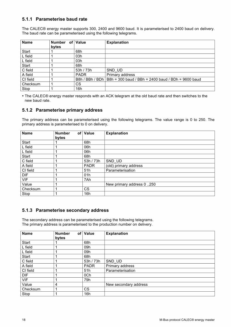
5.1.1 Parameterise baud rate
The CALEC® energy master supports 300, 2400 and 9600 baud. It is parameterised to 2400 baud on delivery. The baud rate can be parameterised using the following telegrams. Name Number of
bytes Value Explanation
Start 1 68h L field 1 03h L field 1 03h Start 1 68h C field 1 53h / 73h SND_UD A field 1 PADR Primary address CI field 1 B8h / BBh / BDh B8h = 300 baud / BBh = 2400 baud / BDh = 9600 baud Checksum 1 CS Stop 1 16h
• The CALEC® energy master responds with an ACK telegram at the old baud rate and then switches to the new baud rate.
5.1.2 Parameterise primary address
The primary address can be parameterised using the following telegrams. The value range is 0 to 250. The primary address is parameterised to 0 on delivery. Name Number of
bytes Value Explanation
Start 1 68h L field 1 06h L field 1 06h Start 1 68h C field 1 53h / 73h SND_UD A field 1 PADR (old) primary address CI field 1 51h Parameterisation DIF 1 01h VIF 1 7Ah Value 1 New primary address 0 ..250 Checksum 1 CS Stop 1 16h
5.1.3 Parameterise secondary address
The secondary address can be parameterised using the following telegrams. The primary address is parameterised to the production number on delivery. Name Number of
bytes Value Explanation
Start 1 68h L field 1 09h L field 1 09h Start 1 68h C field 1 53h / 73h SND_UD A field 1 PADR Primary address CI field 1 51h Parameterisation DIF 1 0Ch VIF 1 79h Value 4 New secondary address Checksum 1 CS Stop 1 16h

M-Bus protocol CALEC® energy master 19
5.1.4 Parameterise response telegram (data selection)
The response telegram can be selected using the following telegram. The telegram always has the same structure. The appropriate DIF, DIFE and VIF must be used depending on the response telegram required. The factory setting for the CALEC® energy master is an active standard telegram. Name Number of
bytes Value Explanation
Start 1 68h L field 1 LEN L field 1 LEN Start 1 68h C field 1 53h / 73h SND_UD A field 1 PADR Primary address CI field 1 51h Parameterisation DIF, DIFE Variable See column "DIF, DIFE" of table “response telegram” VIF 1 See column "VIF" of of table “response telegram” Checksum 1 CS Stop 1 16h
Reply telegram DIF, DIFE VIF Standard 08h 7Eh Billing date 1 48h 7Eh Billing date 2 8801h 7Eh Logger 1 C801h 7Eh Logger 2 8802h 7Eh Logger 3 C802h 7Eh Logger 4 8803h 7Eh Logger 5 C803h 7Eh Logger 6 8804h 7Eh Logger 7 C804h 7Eh Logger 8 8805h 7Eh Logger 9 C805h 7Eh Logger 10 8806h 7Eh etc. Logger 99 C88203h 7Eh Logger 100 888303h 7Eh Service 08h 7Fh
5.1.5 Parameterise date/time
Name Number of bytes
Value Explanation
Start 1 68h L field 1 09h L field 1 09h Start 1 68h C field 1 53h / 73h SND_UD A field 1 PADR Primary address CI field 1 51h Parameterisation DIF 1 04h VIF 1 6Dh Value 4 New date/time Checksum 1 CS Stop 1 16h

20 M-Bus protocol CALEC® energy master
5.1.6 Parameterise billing date 1
Name Number of bytes
Value Explanation
Start 1 68h L field 1 08h L field 1 08h Start 1 68h C field 1 53h / 73h SND_UD A field 1 PADR Primary address CI field 1 51h Parameterisation DIF 1 42h VIF, VIFE 2 EC7Eh Value 2 New billing date 1 Checksum 1 CS Stop 1 16h
• The year figure in the date transmitted is ignored and set internally to 127 (AnyYear). The day and month are adopted.
5.1.7 Parameterise billing date 2
Name Number of bytes
Value Explanation
Start 1 68h L field 1 09h L field 1 09h Start 1 68h C field 1 53h / 73h SND_UD A field 1 PADR Primary address CI field 1 51h Parameterisation DIF, DIFE 2 8201h VIF, VIFE 2 EC7Eh Value 2 New billing date 2 Checksum 1 CS Stop 1 16h
• The year figure in the date transmitted is ignored and set internally to 127 (AnyYear). The day and month are adopted.
5.1.8 Parameterise customer text field 1
Name Number of bytes
Value Explanation
Start 1 68h L field 1 LEN L field 1 LEN Start 1 68h C field 1 53h / 73h SND_UD A field 1 PADR Primary address CI field 1 51h Parameterisation DIF 1 0Dh VIF, VIFE 2 FD11h 1 0h..14h Number of bytes for customer text field Value 0..20 Customer text field (ASCII string) Checksum 1 CS Stop 1 16h • Customer text fields are variable in length. They can be 0 to 20 bytes. The length code can be found between VIFE and the text field.
M-Bus protocol CALEC® energy master 21
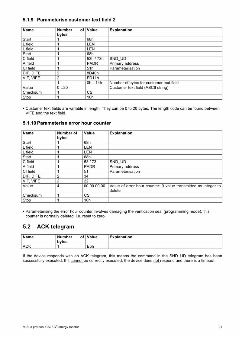
5.1.9 Parameterise customer text field 2
Name Number of bytes
Value Explanation
Start 1 68h L field 1 LEN L field 1 LEN Start 1 68h C field 1 53h / 73h SND_UD A field 1 PADR Primary address CI field 1 51h Parameterisation DIF, DIFE 2 8D40h VIF, VIFE 2 FD11h 1 0h 14h Number of bytes for customer text field Value 0 20 Customer text field (ASCII string) Checksum 1 CS Stop 1 16h
• Customer text fields are variable in length. They can be 0 to 20 bytes. The length code can be found between VIFE and the text field.
5.1.10 Parameterise error hour counter
Name Number of bytes
Value Explanation
Start 1 68h L field 1 LEN L field 1 LEN Start 1 68h C field 1 53 / 73 SND_UD A field 1 PADR Primary address CI field 1 51 Parameterisation DIF, DIFE 2 34 VIF, VIFE 2 22 Value 4 00 00 00 00 Value of error hour counter: 0 value transmitted as integer to
delete Checksum 1 CS Stop 1 16h
• Parameterising the error hour counter involves damaging the verification seal (programming mode); this counter is normally deleted, i.e. reset to zero.
5.2 ACK telegram
Name Number of bytes
Value Explanation
ACK 1 E5h If the device responds with an ACK telegram, this means the command in the SND_UD telegram has been successfully executed. If it cannot be correctly executed, the device does not respond and there is a timeout.

22 M-Bus protocol CALEC® energy master
6 Application reset The CALEC® energy master supports application reset and an extension of it which involves what is known as subcode. The commands only affect the choice of response telegram. Name Number of
bytes Value Explanation
Start 1 68h L field 1 03h (04h) L field 1 03h (04h) Start 1 68h C field 1 53h / 73h SND_UD A field 1 PADR Primary address CI field 1 50h Application reset 0 (1) Subcode Checksum 1 CS Stop 1 16h Subcode Function None Standard telegram 00h Standard telegram B0h Service telegram
7 Variable units The CALEC® energy master transfers all the counter readings in the same format and resolution as they are displayed on the device display.
7.1 Energy units (VIF1)
Resolution Unit VIF (VIFE) 0.001 kWh 03h 0.01 kWh 04h 0.1 kWh 05h 1 kWh 06h 0.001 MWh 06h 0.01 MWh 07h 01 MWh FB00h 1 MWh FB01h 0.001 MJ 0Bh 0.01 MJ 0Ch 0.1 MJ 0Dh 1 MJ 0Eh 0.001 GJ 0Eh 0.01 GJ 0Fh 0.1 GJ FB08h 1 GJ FB09h 0.001 kcal 883Dh 0.01 kcal 893Dh 01 kcal 8A3Dh 1 kcal 8B3Dh 0.001 kBtu 803Dh 0.01 kBtu 813Dh 01 kBtu 823Dh 1 kBtu 833Dh 0.001 MBtu 833Dh 0.01 MBtu 843Dh 0.1 MBtu 853Dh 1 MBtu 863Dh
M-Bus protocol CALEC® energy master 23
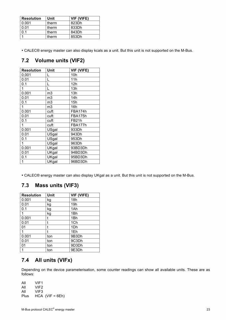
Resolution Unit VIF (VIFE) 0.001 therm 823Dh 0.01 therm 833Dh 0.1 therm 843Dh 1 therm 853Dh
• CALEC® energy master can also display kcals as a unit. But this unit is not supported on the M-Bus.
7.2 Volume units (VIF2)
Resolution Unit VIF (VIFE) 0,001 L 10h 0.01 L 11h 0.1 L 12h 1 L 13h 0.001 m3 13h 0.01 m3 14h 0.1 m3 15h 1 m3 16h 0.001 cuft FBA174h 0.01 cuft FBA175h 0.1 cuft FB21h 1 cuft FBA177h 0.001 USgal 933Dh 0.01 USgal 943Dh 0.1 USgal 953Dh 1 USgal 963Dh 0.001 UKgal 93BD3Dh 0.01 UKgal 94BD3Dh 0.1 UKgal 95BD3Dh 1 UKgal 96BD3Dh
• CALEC® energy master can also display UKgal as a unit. But this unit is not supported on the M-Bus.
7.3 Mass units (VIF3)
Resolution Unit VIF (VIFE) 0.001 kg 18h 0.01 kg 19h 0.1 kg 1Ah 1 kg 1Bh 0.001 t 1Bh 0.01 t 1Ch 01 t 1Dh 1 t 1Eh 0.001 ton 9B3Dh 0.01 ton 9C3Dh 01 ton 9D3Dh 1 ton 9E3Dh
7.4 All units (VIFx) Depending on the device parameterisation, some counter readings can show all available units. These are as follows: All VIF1 All VIF2 All VIF3 Plus HCA (VIF = 6Eh)
24 M-Bus protocol CALEC® energy master
Änderungen vorbehalten / Sous réserve de modifications / Modification rights reserved / Copyright © Aquametro AG SALES PARTNER: HEAD OFFICE: Aquametro AG Ringstrasse 75 CH-4106 Therwil Phone +41 61 725 11 22 Fax +41 61 725 15 95 [email protected]
www.aquametro.com