m com instructions
DESCRIPTION
m Com InstructionsTRANSCRIPT

Laidler Associates
mCom User Manual Machinery Compliance Software – Version 1
2
Contents Installing the software ............................................................................................................................ 4
Running mCom for the First Time ........................................................................................................... 5
Evaluation Mode ................................................................................................................................. 5
Activating mCom Full Version ............................................................................................................. 8
Creating a New Database ........................................................................................................................ 9
Adding a New Project.............................................................................................................................. 9
Adding a Machine to a Project .............................................................................................................. 10
Displaying the Questions ...................................................................................................................... 10
Answer a Question ............................................................................................................................ 10
Adding a Risk Assessment ..................................................................................................................... 11
Edit a Risk Assessment ...................................................................................................................... 12
Delete a Risk Assessment .................................................................................................................. 12
Copy a Risk Assessment .................................................................................................................... 13
The Main Risk Assessment Pool ........................................................................................................ 13
Standards .............................................................................................................................................. 14
Adding a New Standard .................................................................................................................... 14
Machine Documents ............................................................................................................................. 15
Declaration of Conformity .................................................................................................................... 17
Declaration of Incorporation ................................................................................................................ 18
Control Integrity .................................................................................................................................... 19
EN 62061 Assessment ....................................................................................................................... 19
EN 13849 Assessment ....................................................................................................................... 20
EN 954 Assessment ........................................................................................................................... 21
EN 954 Overview ........................................................................................................................... 22
Table 1: Guide to EN 954-1 category requirements ..................................................................... 24
Table 2: Sample Circuit Diagrams ................................................................................................. 25
Copy / Move Machine ........................................................................................................................... 27
Merge Database .................................................................................................................................... 28
Import Risks .......................................................................................................................................... 29
Export to Excel ...................................................................................................................................... 29
Spell Check Project ................................................................................................................................ 30
Site Overview Chart .............................................................................................................................. 30
Photographs .......................................................................................................................................... 31

3
Adding Project Photographs ............................................................................................................. 31
Adding Photographs to Risk Assessments ........................................................................................ 31
Reports .................................................................................................................................................. 32
To Do Report ..................................................................................................................................... 32
Checklist Report ................................................................................................................................ 32
Blank Checklist Report ...................................................................................................................... 32
Standards Report .............................................................................................................................. 33
Machines Report ............................................................................................................................... 33
History of Risk Assessment within the EEA ........................................................................................... 34
PUWER 98 (United Kingdom Legislation).............................................................................................. 35
Definitions ..................................................................................................................................... 37
Risk Assessment Process (HRN) ........................................................................................................ 38
Risk Assessment Chart. ................................................................................................................. 39
Other Common Risk Assessment Methods .................................................................................. 39
Hazard Identification ..................................................................................................................... 40
Common Hazard Categories ............................................................................................................. 41
Preliminary Hazard Analysis using Hazard Rating Number System .................................................. 42
Hazard Rating Number System Chart ........................................................................................... 43
Guidance Timeframes ................................................................................................................... 44
Control Measures .............................................................................................................................. 44
Risk Assessment Example ................................................................................................................. 44
Glossary of Terms.................................................................................................................................. 46
4
Installing the software
During installation, it may be necessary to restart your PC. This happens when files that need to be
updated are currently in use. On some Windows systems these files are also classed as protected
files and cannot be updated without rebooting.
Insert the mCom CD into your CD/DVD drive.
If the installer does not Auto run then go to My Computer.
Locate your CD/DVD and double click to run the CD.
The mCom Install Window should appear.
Install the Risk Software by following the on-screen instructions. To update your system the PC may
need to restart. After the restart you may need to run the setup a second time to continue the
installation process but this should happen automatically.
5
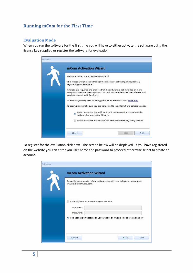
Running mCom for the First Time
Evaluation Mode
When you run the software for the first time you will have to either activate the software using the
license key supplied or register the software for evaluation.
To register for the evaluation click next. The screen below will be displayed. If you have registered
on the website you can enter you user name and password to proceed other wise select to create an
account.
6
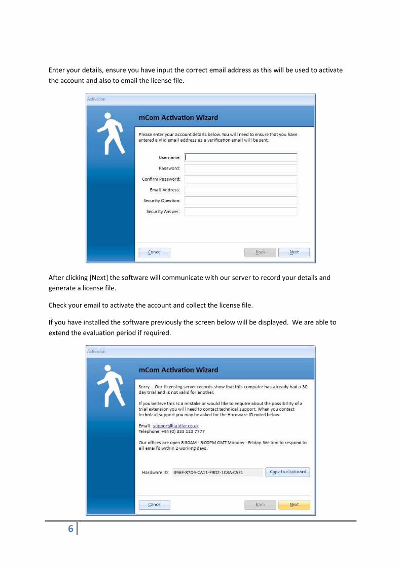
Enter your details, ensure you have input the correct email address as this will be used to activate
the account and also to email the license file.
After clicking [Next] the software will communicate with our server to record your details and
generate a license file.
Check your email to activate the account and collect the license file.
If you have installed the software previously the screen below will be displayed. We are able to
extend the evaluation period if required.

7
Once you have the license file, copy it from your email to your PC. In the mCom activation wizard
browse to the file location and open the license file. The software will now run in evaluation mode
for 30 days.
Evaluation mode restricts the questions in the software to three per section and also disables the
checklist reports.
8
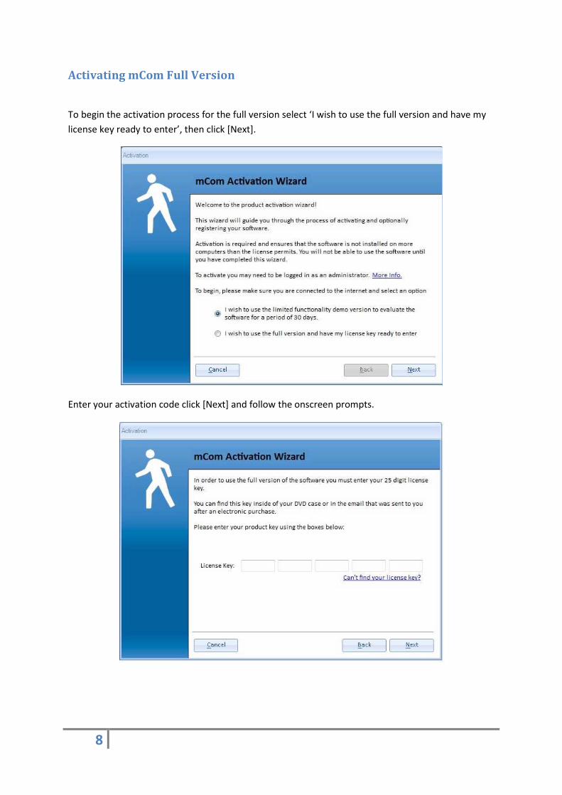
Activating mCom Full Version
To begin the activation process for the full version select ‘I wish to use the full version and have my
license key ready to enter’, then click [Next].
Enter your activation code click [Next] and follow the onscreen prompts.

9
Creating a New Database
When mCom is opened for the first time it uses the default database located in the software’s
application folder in Program Files. It is possible to use the default database but it’s a good idea to
create a new database for the assessments named correctly for your project and stored in location
on your PC. It’s also recommended that you store your database locally. If you store your database
on a file server, you may encounter slow response times from the software.
To create a new database, select the [Database Functions] menu and select the [New Database]
option.
In the dialog window that appears, locate the folder to store the new database and enter a file
name. Once complete, click [Save].
You have now created a database. mCom databases use the file extension of .vdb3
Adding a New Project
A project in the software sets the questions for the assessment. Selecting a CE Marking project will
load questions for CE Marking, a PUWER project will load the PUWER’98 questions and so on. A
project can only contain one type of questions, so you can’t mix PUWER and CE Marking within one
project. You can however have two projects (one CE Marking and one PUWER) within the same
database. In fact you can have as many projects as you require in one database.
In the [Project Functions] menu section select [New Project].
In the screen that’s displayed select the project type you require.
• CE Marking -Full CE Marking checklist
• PUWER98 -Full PUWER’98 checklist
• P and P -PUWER’98 Policies and Procedures section
• PUWER Electrical -PUWER’98 Electrical question only – Used for electrical panels etc.
After making the selection, complete the text boxes with the relevant information. Some of the
information input here may be used in other parts of the software, such as company name and
address. It can be changed at anytime from the projects screen.
To delete a project, firstly select the project in the tree view and click the [Activate Delete] button.
You will see the button text change to [Delete Project]. You will then see a couple of prompts before
the delete takes place. ALL project data will be deleted with NO backup.

10
Adding a Machine to a Project
With a project selected in the tree view, click the [Add Machine] button in the Project Functions
menu. A screen will be displayed with a number of text boxes to be completed with the machine
details. Complete the details as required and click [Save]. The machine will now appear on the tree
view list within the Project section.
The [Last Used] button on this screen will automatically complete the Location, Building and area
fields using the values you entered from the last machine. These values are only stored while the
application is running; once the application is closed the values are disregarded.
To delete a machine, firstly select the project in the tree view and click the [Activate Delete] button.
You will see the button text change to [Delete Machine]. You will then see a couple of prompts
before the delete takes place. ALL machine data will be deleted including risk assessments and any
attached photographs.
Displaying the Questions
To display the Questions/Answers screen, double click on a machine in the tree view. The screen
will change to display the questions related to the project you created in an earlier stage.
Clicking the + icon or double clicking the text on the tree view will expand the sections to list sub
sections and then the questions for your chosen project.
Answer a Question
Select a question from the tree view. Select the answer you require from the radio buttons on the
right side of the screen, Yes, No and Not Applicable. The software is designed around positive
answers. In most cases the positive answer is Yes, but some questions have a positive answer of No.
A positive answer is displayed with a green tick next to the radio button and the answer text is
inserted into the answer text box. The question icon is changed to green in the tree view displaying
a positive answer for that question. Once you are happy with the answer click [Save].
The default answer text can be modified if required.
Clicking the [Reset] button will reset the question to an unanswered state.
The [Roll Back] button is used when editing an answer. If you have made changes to an already
saved answer and wish to disregard the changes, the [Roll Back] button will return the answer to the
state it was last saved as.
You can also add comments to an answer to maybe explain the answer in more detail or give further
information.

11
Giving a negative answer to a question will prompt you to enter a risk assessment. In most cases
‘No’ is the negative answer. When clicking the [No] radio button the text (See Risk Assessments)
appears in the Answer text box. When you click [Save] the [Risk Assessments] button becomes
available (see adding risk assessments).
The [< Previous] and [Next >] buttons will display the associated question in the section.
Adding a Risk Assessment
After answering a question with a negative answer the [Risk Assessments] button becomes available.
Click the [Risk Assessments] button to view the risk assessments associated with the
machine/question.
When using the software for the first time no risk assessments will be available. The Machine Risk
Assessment Pool screen will show empty grid views.
Lets get started and add a new risk assessment. Click [Add Risk]. The Hazard Rating Number (HRN)
screen will be displayed displaying four tabs, Hazard, Control Measure, Notes and Photographs.
Start by entering the hazard description in to the Hazard text box.
Using your skill and judgement select the initial assessment from the drop down boxes:
• Likelihood of Occurrence (LoO)
• Degree of Possible Harm (DoPH)
• Frequency of Exposure (FoE)
• Number of People at Risk (NoPaR)
You may also enter the After Control assessment if you are confident of the values required. The
sort number field on this screen is used to reference the hazard and can be changed to any integer
number if required. It’s used as a reference only and not displayed on any reports.
The introduced date field displays the date and time that the risk assessment was created and the
Last Modified fields shows the last time any changes were made to the risk assessment.
To enter a Control Measure description click on the [Control Measures] tab at the top of the screen
and enter the control measures description to eradicate the risk. If you have not already, you should
enter the control measures hazard rating values at this point. The After Control values should be
chosen as if the control measures have been carried out.
The Carried out by field on this tab is to display the name of the person assigned to carry the actual
work out on the machinery. It will default to the company name until it is changed by the user.
The Recommended Completion Date is the expected date for the work to be carried out.
The implemented date is the actual date that the work was carried out. Once it is confirmed that
the control measures work is complete and correct, the risk assessment can be implemented by
selecting the implemented date and clicking the [Set to Implemented] button. If no date has been

12
set for the implemented date, the current date and time will be used. Once a risk assessment has
been implemented, it cannot be changed or deleted.
Clicking the [Notes] tab will display the notes screen for the current risk assessment.
Clicking the [Photographs] tab will display the photographs screen for the current risk assessment,
we will cover this screen later in the manual.
Once you’ve completed the various screens that make up the risk assessment click the [Close]
button. The risk assessment saves the data as you enter it, hence there’s no save button. After
clicking close you are returned to the HRN Pool, you will now see your risk assessment in the top grid
view.
The top grid view shows risk assessments that are linked to the machine you are assessing. To link
the risk assessment to the question you have just answered you must click the check box in the
‘Linked’ column in the top grid view. The risk assessment will now appear in the To Do report and
the Checklist report for the current machine/project.
The [Colour Key] button will open a screen to show the meaning of the row colours of the risk
assessments.
Edit a Risk Assessment
To edit an existing risk assessment either double click it in the grid view or select it from the grid
view and click the [Edit Risk] button. Make the changes you require and click [Close]. All edits are
saved on closing the screen.
Delete a Risk Assessment
Select the risk assessment from the machine grid view. Ensure you have selected the correct risk
assessment before clicking the [Delete Risk] button. You will be prompted to delete the risk before
the risk is removed.
If as risk assessment is linked to a question it must be unlinked (untick the ‘Linked’ tick box) before it
can be deleted.

13
Risk assessments that are coloured light pink denote that they are attached to another question.
When you select a pink risk assessment and click delete you will be shown the questions that this
risk assessment is linked to. At which point you can choose to go ahead with the delete or cancel.
Copy a Risk Assessment
Risk assessments are copied in the Machine Risk Assessment Pool screen. Clicking the [Machine
Pool] button will show the risk assessment attached to the machine, weather they’re linked to a
question or not. They are displayed in the bottom grid view. To copy an assessment, select it in the
bottom grid view and then drag and drop it in the top grid view. This operation has now created a
new risk assessment, which can be edited as normal. Also, note the colour of the copy, being Khaki.
This colour shows that this is the latest risk assessment to be added to the machine and is used
simply as a reference. The colour will be replaced if overridden by another process i.e. linked to a
question or implemented.
The Main Risk Assessment Pool
As well as the machine risk assessment pool the software can store common risk assessments in the
Main Assessment Pool allowing the ability to copy from the main pool to machine pool.
There are two methods to add risk assessments to the Main Pool.
1. From the Machine Risk Assessment Pool screen, select a risk assessment from the top grid
view. Clicking [Add to Pool] will make a copy of the selected risk assessment in the Main
pool.
2. If you are in the Risk Assessment Pool screen, close the screen and select [Assessment Pool]
from the Project Functions menu.
The Main Assessment Pool screen, allows you to add new risk assessments to the Main Pool
as well as edit and delete them in the same way as the Risk Assessment Pool screen. The
[Full Text] button on this screen will reload the grid view to display the full text of the Hazard
Description. After clicking [Full Text] the button will change to [Show Short Text], clicking
this will revert the display to show one row per assessment.
You’ll notice on the Main Assessment Pool that there is a [Save] button. You can edit the
Hazard Description or Control Measures descriptions in the text boxes at the top of the
screen and press [Save] to save the changes.
14
Standards
On the questions screen you’ll see the [Standards] button. Clicking this will display the list of
standards held within the software. Due to copyright we can only display the title and description of
the standard. The standards list is also accessible from the Project Functions menu. Accessing the
standards through the menu does not allow linking the standards to questions but is used for editing
the standards list only.
You can link a standard to a question my simply clicking the tick box in the Select column and then
clicking [Add to Question].
You can edit a standard by double clicking the standard in the grid view or by selecting it and clicking
the [Edit] button.
To delete a standard, select it from the grid view and click [Delete]. You will be prompted before the
deletion is made.
The import function will import a list of standards held in a Microsoft Excel file. The Excel file must
be of the correct format for the import to work.
The Excel Workbook sheet must be names ‘Sheet1’
Column 1: Prefix
Column 2: Standard Number
Column 3: Part Number
Column 4: Standard title
Column 5: Standard Description
Column 6: Standard type – A, B or C
After clicking the [Import] button, the Import Standards screen is displayed. Click [Browse] and
locate the Excel file to import. Once select click the [Import] button to start the import process. You
will be prompted when the import is complete.
The [Standard Type] drop down box allows you to select the type of standards displayed in the grid
view, either All, A only, B only or C only.
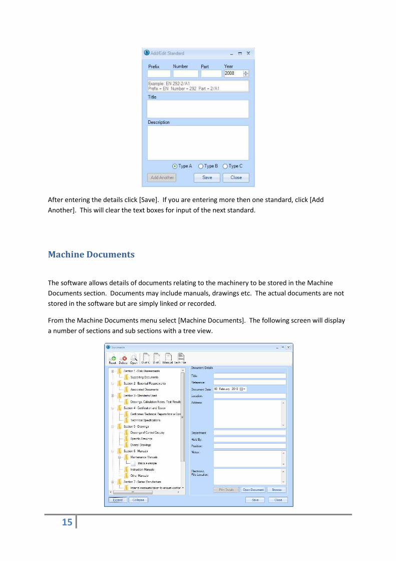
Adding a New Standard
To add a new standard click the [Add] button. A new screen is displayed with text boxes to be
completed.
15
After entering the details click [Save]. If you are entering more then one standard, click [Add
Another]. This will clear the text boxes for input of the next standard.
Machine Documents
The software allows details of documents relating to the machinery to be stored in the Machine
Documents section. Documents may include manuals, drawings etc. The actual documents are not
stored in the software but are simply linked or recorded.
From the Machine Documents menu select [Machine Documents]. The following screen will display
a number of sections and sub sections with a tree view.

16
To add a new document to the documents list, select a subsection from the tree view and enter the
document details in the text boxes. If you wish to link to an electronic file held on your IT system,
click the [Browse] button and locate the file. Once the details are complete click [Save].
Any linked documents can be viewed by clicking the [Open Document] button. It must be noted that
software capable of opening the linked file must be installed on your PC. If an Autocad drawing is
linked then, you must have Autocad installed or a software package able to view an Autocad
drawing. This obviously goes for any file format linked in to the software.
The details can be printed using the [Print Details] button, to open a print preview of the report.
The [Expand] and [Collapse] buttons are used to expand and collapse the tree view sections.
[Reset] will clear the text boxes of any data displayed.
[Delete] will delete the currently selected document . This will not delete any actual documents
linked to the details.
[Open] will attempt to open the linked document.
[D of C] – Declaration of Conformity, clicking this button will display the Declaration of Conformity
screen.
[D of I] - Declaration of Incorporation, clicking this button will display the Declaration of
Incorporation screen.
[Manual] – Clicking the manual button will prompt you to save the manual template on your system.
The template outlines the sections required for the machinery manual.
[Tech File] – Clicking [Tech File] will prompt you to save the tech file template on your system. The
template outlines the sections required within the Technical Construction File.

17
Declaration of Conformity
The Declaration of Conformity can be found on the machine documents screen. After clicking the [D
of C] button, the Declaration of Conformity screen is displayed.
The software will populate any fields with data input in to the project at other stages. This may not
necessarily be correct but can be changed and saved as required. You can only store one
Declaration of Conformity per machine.
The function buttons on this screen work as you would expect:
[Save] will save the data input.
[Print] will print the Declaration of Conformity certificate.
[Reset] will clear all text boxes on the screen.
[Delete] will delete any stored data and clear the text boxes.
18
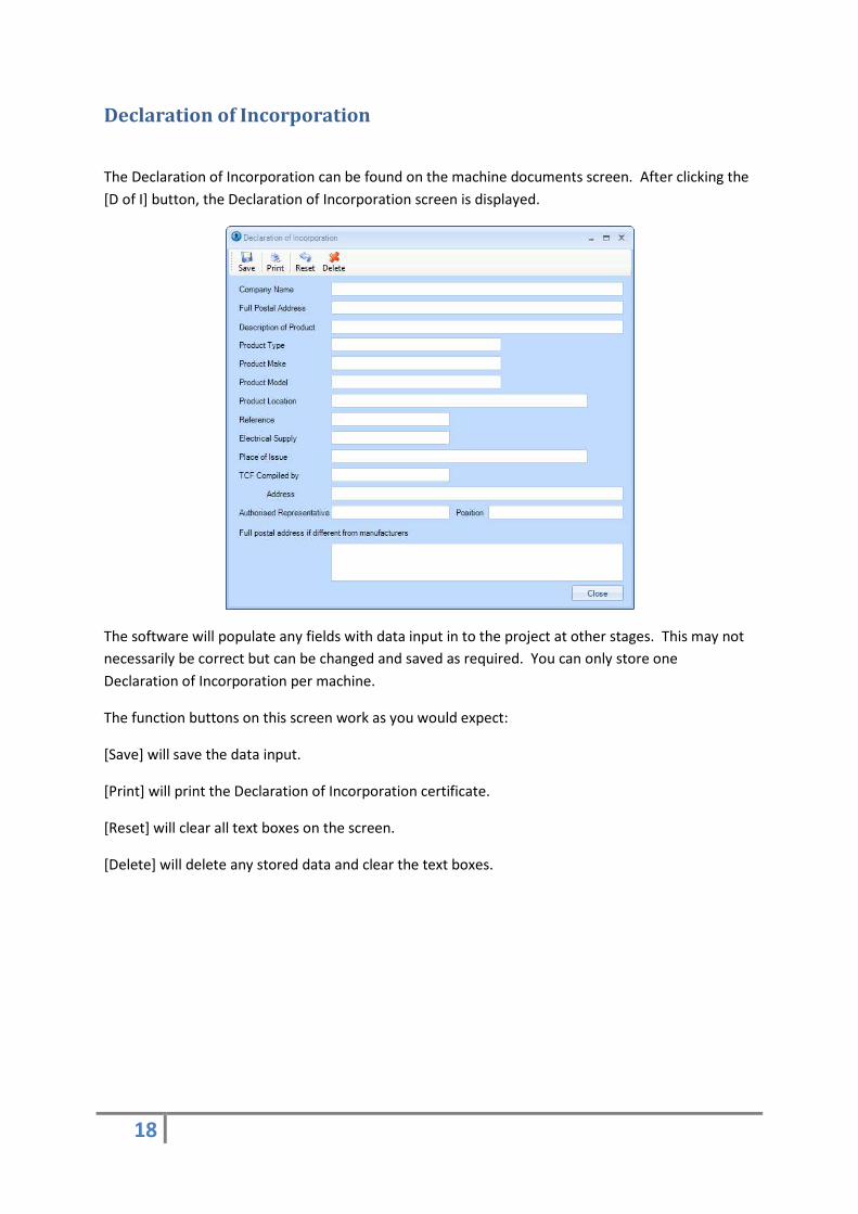
Declaration of Incorporation
The Declaration of Incorporation can be found on the machine documents screen. After clicking the
[D of I] button, the Declaration of Incorporation screen is displayed.
The software will populate any fields with data input in to the project at other stages. This may not
necessarily be correct but can be changed and saved as required. You can only store one
Declaration of Incorporation per machine.
The function buttons on this screen work as you would expect:
[Save] will save the data input.
[Print] will print the Declaration of Incorporation certificate.
[Reset] will clear all text boxes on the screen.
[Delete] will delete any stored data and clear the text boxes.
19
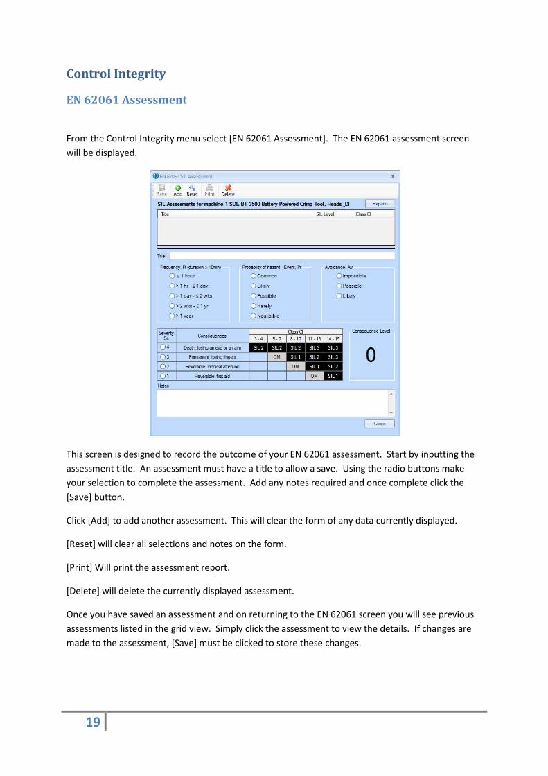
Control Integrity
EN 62061 Assessment
From the Control Integrity menu select [EN 62061 Assessment]. The EN 62061 assessment screen
will be displayed.
This screen is designed to record the outcome of your EN 62061 assessment. Start by inputting the
assessment title. An assessment must have a title to allow a save. Using the radio buttons make
your selection to complete the assessment. Add any notes required and once complete click the
[Save] button.
Click [Add] to add another assessment. This will clear the form of any data currently displayed.
[Reset] will clear all selections and notes on the form.
[Print] Will print the assessment report.
[Delete] will delete the currently displayed assessment.
Once you have saved an assessment and on returning to the EN 62061 screen you will see previous
assessments listed in the grid view. Simply click the assessment to view the details. If changes are
made to the assessment, [Save] must be clicked to store these changes.
20
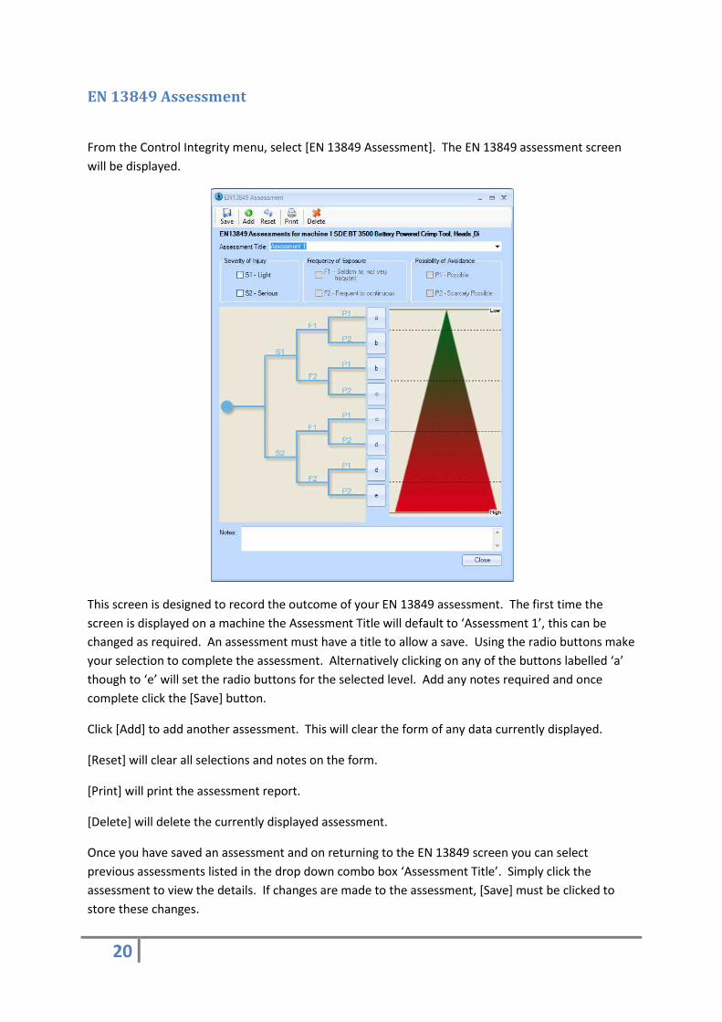
EN 13849 Assessment
From the Control Integrity menu, select [EN 13849 Assessment]. The EN 13849 assessment screen
will be displayed.
This screen is designed to record the outcome of your EN 13849 assessment. The first time the
screen is displayed on a machine the Assessment Title will default to ‘Assessment 1’, this can be
changed as required. An assessment must have a title to allow a save. Using the radio buttons make
your selection to complete the assessment. Alternatively clicking on any of the buttons labelled ‘a’
though to ‘e’ will set the radio buttons for the selected level. Add any notes required and once
complete click the [Save] button.
Click [Add] to add another assessment. This will clear the form of any data currently displayed.
[Reset] will clear all selections and notes on the form.
[Print] will print the assessment report.
[Delete] will delete the currently displayed assessment.
Once you have saved an assessment and on returning to the EN 13849 screen you can select
previous assessments listed in the drop down combo box ‘Assessment Title’. Simply click the
assessment to view the details. If changes are made to the assessment, [Save] must be clicked to
store these changes.
21
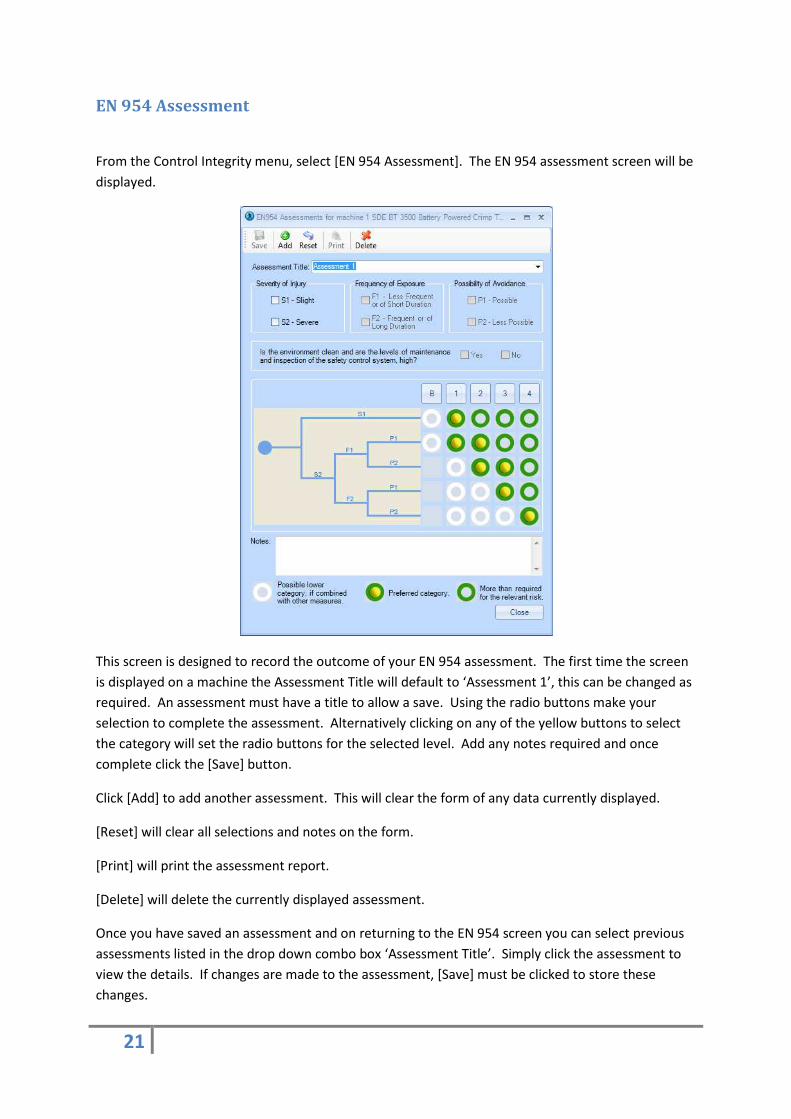
EN 954 Assessment
From the Control Integrity menu, select [EN 954 Assessment]. The EN 954 assessment screen will be
displayed.
This screen is designed to record the outcome of your EN 954 assessment. The first time the screen
is displayed on a machine the Assessment Title will default to ‘Assessment 1’, this can be changed as
required. An assessment must have a title to allow a save. Using the radio buttons make your
selection to complete the assessment. Alternatively clicking on any of the yellow buttons to select
the category will set the radio buttons for the selected level. Add any notes required and once
complete click the [Save] button.
Click [Add] to add another assessment. This will clear the form of any data currently displayed.
[Reset] will clear all selections and notes on the form.
[Print] will print the assessment report.
[Delete] will delete the currently displayed assessment.
Once you have saved an assessment and on returning to the EN 954 screen you can select previous
assessments listed in the drop down combo box ‘Assessment Title’. Simply click the assessment to
view the details. If changes are made to the assessment, [Save] must be clicked to store these
changes.
22
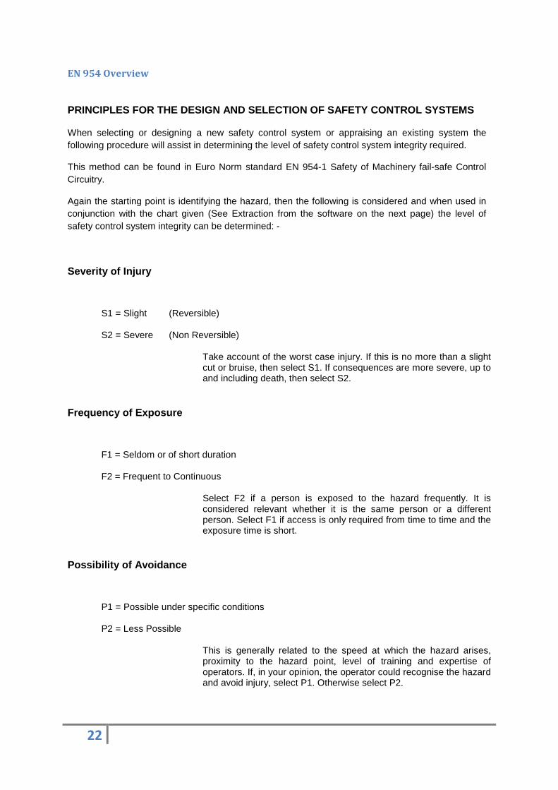
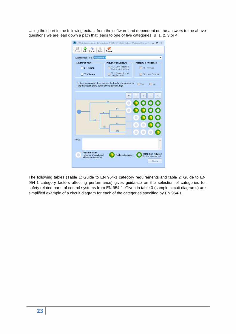
EN 954 Overview
PRINCIPLES FOR THE DESIGN AND SELECTION OF SAFETY C ONTROL SYSTEMS
When selecting or designing a new safety control system or appraising an existing system the following procedure will assist in determining the level of safety control system integrity required.
This method can be found in Euro Norm standard EN 954-1 Safety of Machinery fail-safe Control Circuitry.
Again the starting point is identifying the hazard, then the following is considered and when used in conjunction with the chart given (See Extraction from the software on the next page) the level of safety control system integrity can be determined: -
Severity of Injury
S1 = Slight (Reversible)
S2 = Severe (Non Reversible)
Take account of the worst case injury. If this is no more than a slight cut or bruise, then select S1. If consequences are more severe, up to and including death, then select S2.
Frequency of Exposure
F1 = Seldom or of short duration
F2 = Frequent to Continuous
Select F2 if a person is exposed to the hazard frequently. It is considered relevant whether it is the same person or a different person. Select F1 if access is only required from time to time and the exposure time is short.
Possibility of Avoidance
P1 = Possible under specific conditions
P2 = Less Possible
This is generally related to the speed at which the hazard arises, proximity to the hazard point, level of training and expertise of operators. If, in your opinion, the operator could recognise the hazard and avoid injury, select P1. Otherwise select P2.
23
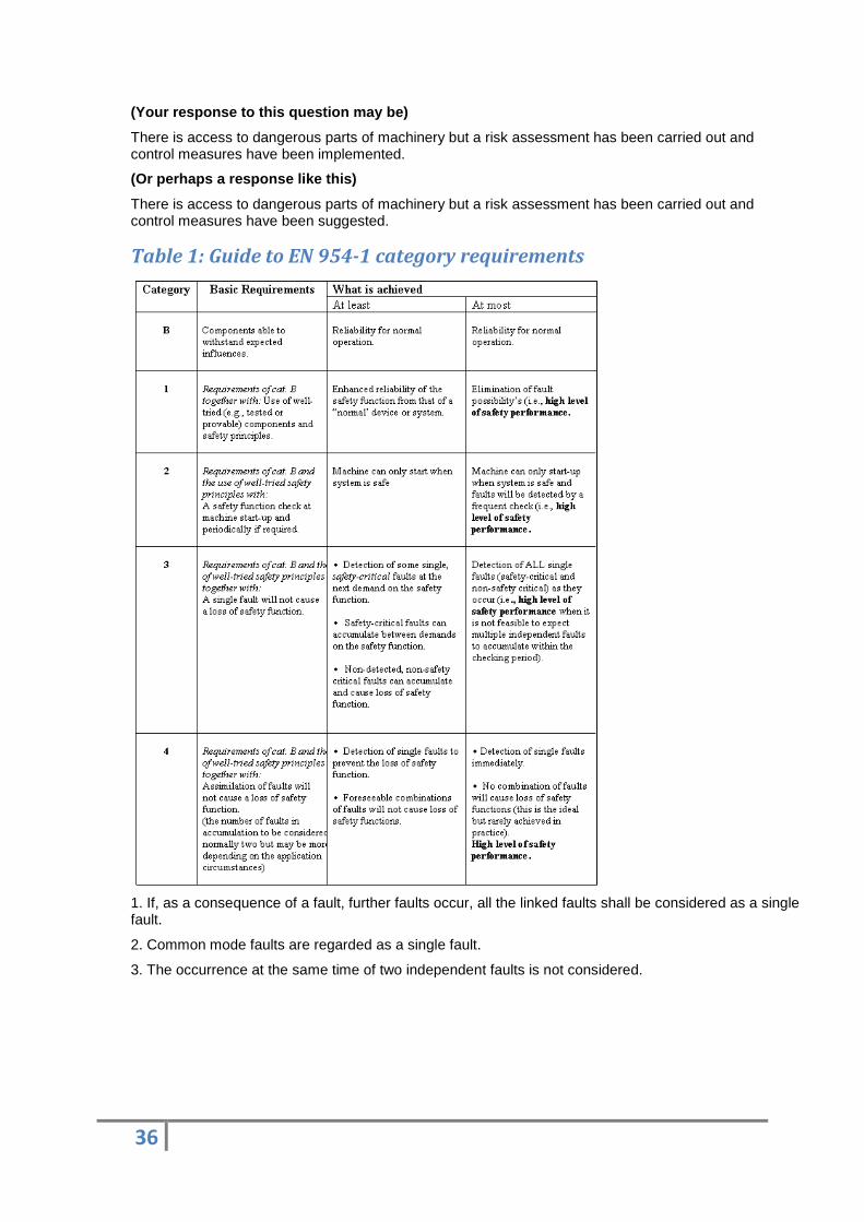
Using the chart in the following extract from the software and dependent on the answers to the above questions we are lead down a path that leads to one of five categories: B, 1, 2, 3 or 4.
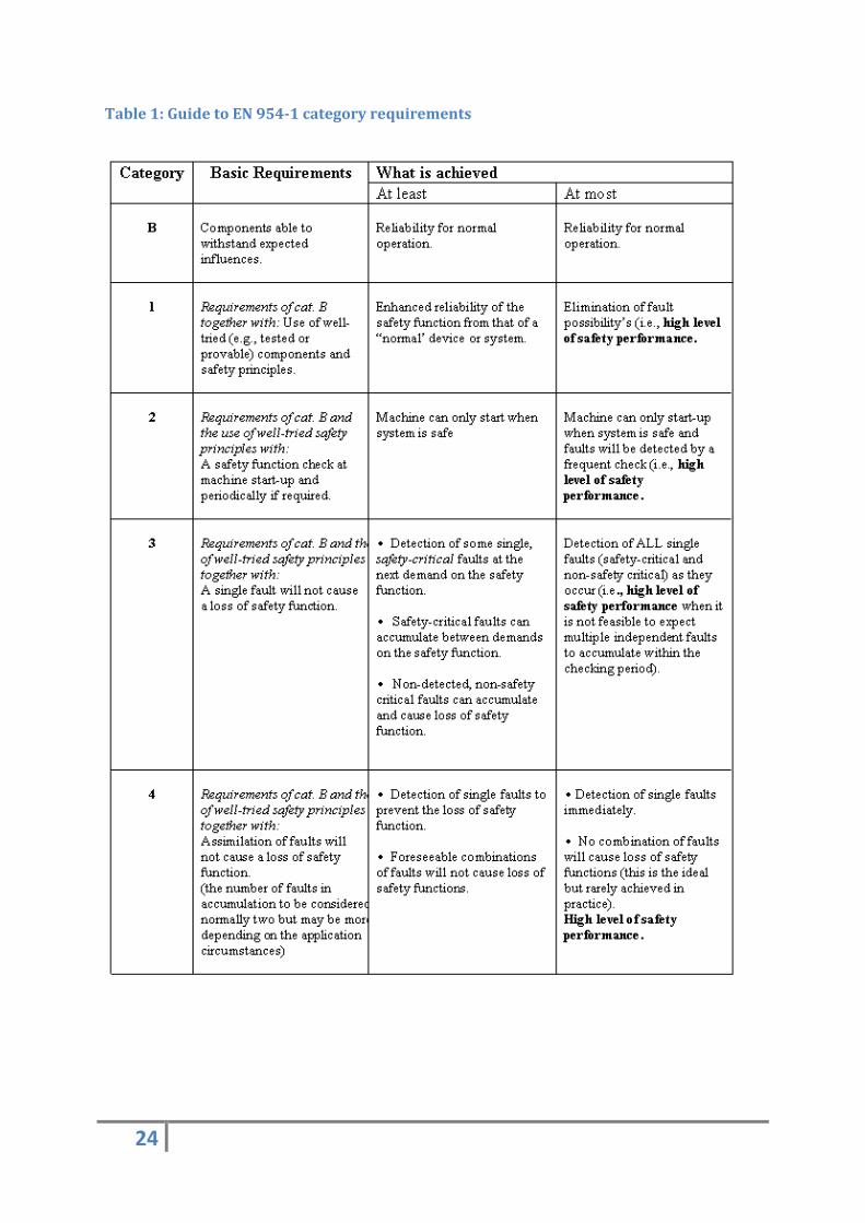
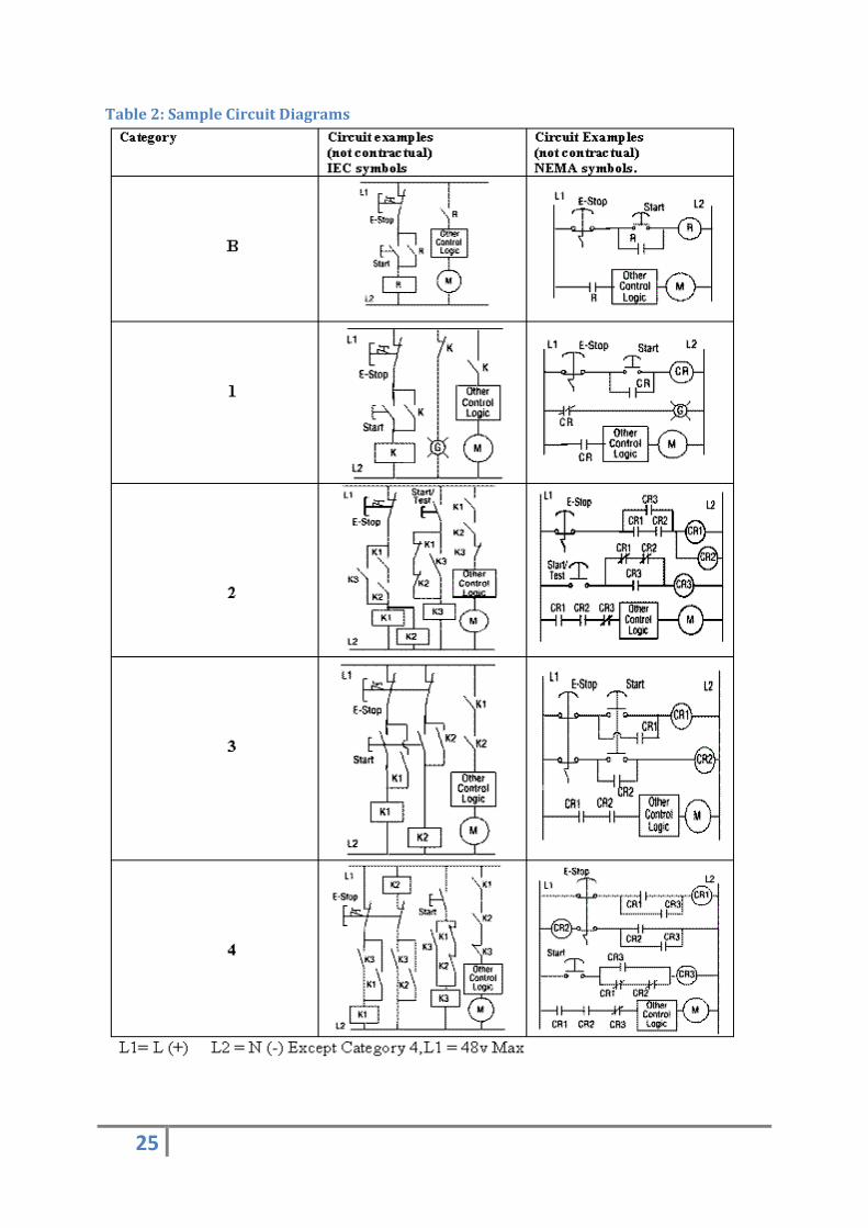
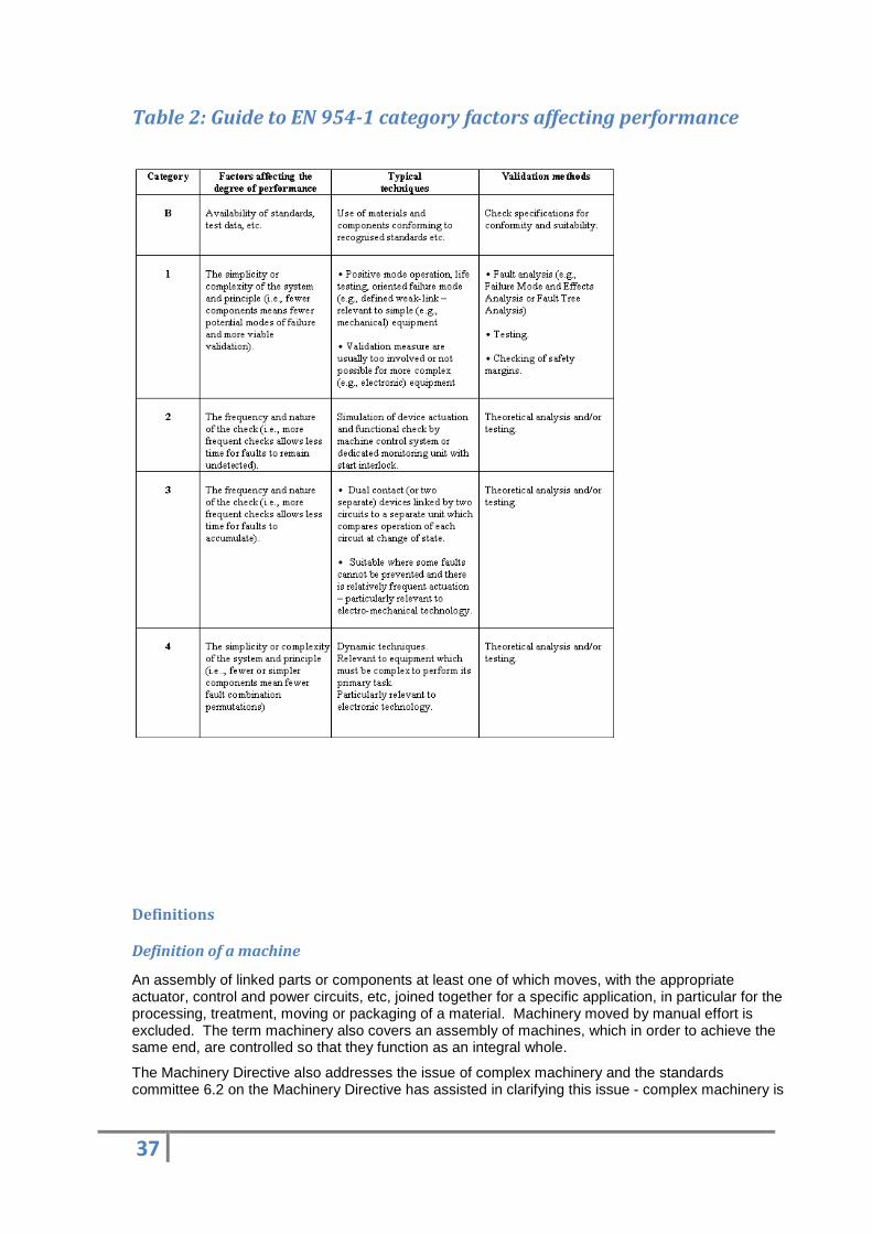
The following tables (Table 1: Guide to EN 954-1 category requirements and table 2: Guide to EN 954-1 category factors affecting performance) gives guidance on the selection of categories for safety related parts of control systems from EN 954-1. Given in table 3 (sample circuit diagrams) are simplified example of a circuit diagram for each of the categories specified by EN 954-1.
24
Table 1: Guide to EN 954-1 category requirements
25
Table 2: Sample Circuit Diagrams
26
This assessment is an extract from EN 954 part 1 and can be used to categorise your safety related control systems. Multiple assessments can be performed using this package by addressing each control system in turn. The available options allow the manipulation of the information supplied (See the following example from the software).
Note: You must reference the complete EN 954 part 1 standard in order to fully comply.
27
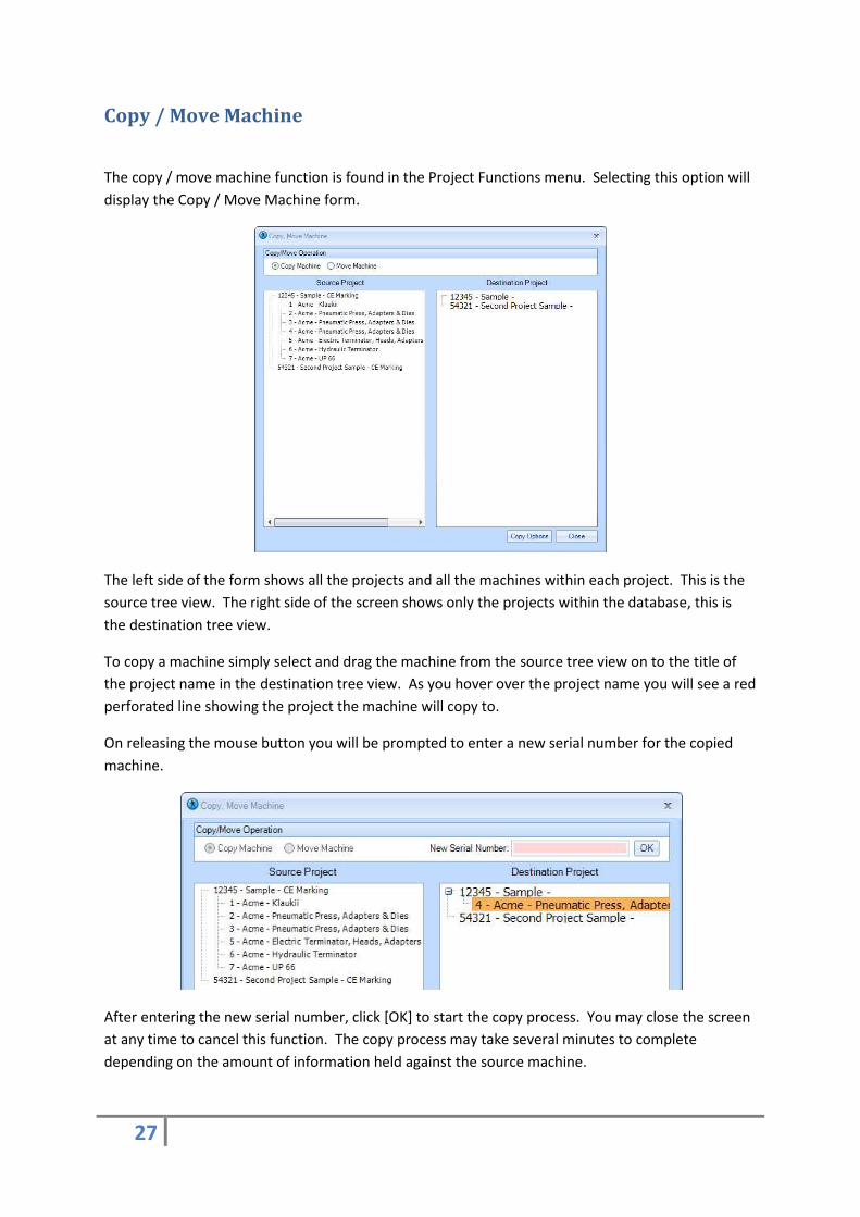
Copy / Move Machine
The copy / move machine function is found in the Project Functions menu. Selecting this option will
display the Copy / Move Machine form.
The left side of the form shows all the projects and all the machines within each project. This is the
source tree view. The right side of the screen shows only the projects within the database, this is
the destination tree view.
To copy a machine simply select and drag the machine from the source tree view on to the title of
the project name in the destination tree view. As you hover over the project name you will see a red
perforated line showing the project the machine will copy to.
On releasing the mouse button you will be prompted to enter a new serial number for the copied
machine.
After entering the new serial number, click [OK] to start the copy process. You may close the screen
at any time to cancel this function. The copy process may take several minutes to complete
depending on the amount of information held against the source machine.

28
To move a machine the process is the same, but you will not be required to enter a new serial
number. Ensure you have selected the [Move Machine] radio button before dragging and dropping
the selected machine. The move process should only take a few seconds to complete.
Merge Database
The [Merge Database] function can be found in the Database Functions menu. Currently this feature
allows a single machine to be imported from another .VDB3 database. After selecting the Merge
Database screen is displayed.
Firstly select the database you wish to copy a machine from by clicking the [Choose File to Import]
button]. An open file dialog is displayed. From here locate the file to import and click [Open].
A list of projects and machines will be listed in the tree view. Select the machine you wish to import
and click the [Import] button. A prompt will be displayed asking to select a project to copy the
machine to. Click [OK] on this prompt and you will observe the tree view contents change to the
destination databases projects. Select the project you want to copy the machine in to and once
again click [Import]. The import process will now begin.
A prompt will appear when the process is complete.
29
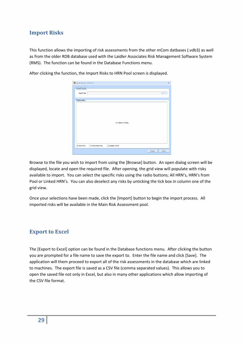
Import Risks
This function allows the importing of risk assessments from the other mCom datbases (.vdb3) as well
as from the older RDB database used with the Laidler Associates Risk Management Software System
(RMS). The function can be found in the Database Functions menu.
After clicking the function, the Import Risks to HRN Pool screen is displayed.
Browse to the file you wish to import from using the [Browse] button. An open dialog screen will be
displayed, locate and open the required file. After opening, the grid view will populate with risks
available to import. You can select the specific risks using the radio buttons; All HRN’s, HRN’s from
Pool or Linked HRN’s. You can also deselect any risks by unticking the tick box in column one of the
grid view.
Once your selections have been made, click the [Import] button to begin the import process. All
imported risks will be available in the Main Risk Assessment pool.
Export to Excel
The [Export to Excel] option can be found in the Database functions menu. After clicking the button
you are prompted for a file name to save the export to. Enter the file name and click [Save]. The
application will them proceed to export all of the risk assessments in the database which are linked
to machines. The export file is saved as a CSV file (comma separated values). This allows you to
open the saved file not only in Excel, but also in many other applications which allow importing of
the CSV file format.
30
Spell Check Project
After selecting the project to be spellchecked form the tree view, click the [Spell Check Project]
button in the Project functions menu. The spell check screen will be displayed giving options on
which part of the project you wish to check. It will default to the whole project.
Once you’ve made your selection, click [Spellcheck]. When the system will display the text it’s
checking the text box. When a mistake is found, a red underline denotes the mistake and a
correction box is displayed. After making the correction the system will continue to check the rest of
the project until it completes all the required fields.
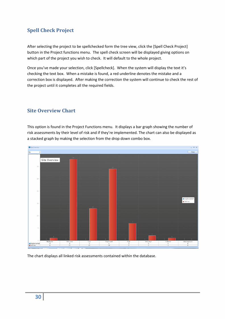
Site Overview Chart
This option is found in the Project Functions menu. It displays a bar graph showing the number of
risk assessments by their level of risk and if they’re implemented. The chart can also be displayed as
a stacked graph by making the selection from the drop down combo box.
The chart displays all linked risk assessments contained within the database.
31
Photographs
Adding Project Photographs
This option is found in the Project Functions menu. After clicking the Project Photographs screen is
displayed. To add photographs in to the database, click the [Add] button. An open dialog is
displayed. Locate and select the photograph you wish to include and click [Open] or double click the
image. You can select more then one photograph by holding [CTRL] and selecting the images or by
dragging the selection box across all the required images.
To add a comment to an image, double click the image to display the Image Comments screen.
Enter the comment in the text box and click [Close]. You can add comments to further photographs
by clicking [Next] or [Previous] to step through all the photographs you’ve imported.
To delete an imported image, select it from the list view and click [Delete]. This will remove the
image from the database not from your system.
To print the photographs, simply click the [Print Preview] button to generate the report.
Adding Photographs to Risk Assessments
To add photographs to a risk assessment you must first locate and view the risk assessment you wish
to add the photographs to. Once you have the risk assessment screen open click on the
Photographs tab. To add a photograph, click on the [Browse] button to display an open dialog.
Locate and select the required image or images using the [CTRL] key to make a multi selection, then
click open to copy the image in to the database.
To add a comment to an image, double click the image to display the Image Comments screen.
Enter the comment in the text box and click [Close]. You can add comments to further photographs
by clicking [Next] or [Previous] to step through all the photographs you’ve imported.
To delete an imported image, select it from the list view and click [Delete]. This will remove the
image from the database not from your system.
The photographs are printed on the To Do report when you select ‘Include Photos attached to risks.’
In the To Do report options screen.
32
Reports
To Do Report
The To Do Report prints out the selected risk assessments. From the To Do report options screen
you can select to print the standard report, a short report, which has some of the more detailed
areas of the risk assessment removed or a To Do report including any attached photographs.
You can also choose to print either, the whole database, whole project or a single machine. By
default, the software selects to print both outstanding and implemented risk assessments. You can
select to print outstanding only or implemented only.
Depending on the amount of machines in a project and number of risk assessments attached the
report can take from a few seconds to several minutes to generate as it gathers and formats all the
required information.
Checklist Report
The checklist report shows how the questions were answered, which risk assessment and standards
are attached to the question. By default only the questions that have been answered will be output
to the report, but you can choose to print all questions in he options screen.
You can also choose to print either, the whole database the whole project or a single machine. By
default, the software selects to print both outstanding and implemented risk assessments. You can
select to print outstanding only or implemented only.
Depending on the amount of machines in a project and number of risk assessments attached the
report can take from a few seconds to several minutes to generate as it gathers and formats all the
required information.
Blank Checklist Report
The blank checklist report prints all questions in the project. The report leaves space for answers to
be hand written on to the sheet.
To generate a blank checklist you must add a project and machine into the application. This can
simply be a dummy machine if required.

33
Standards Report
The standards report prints all standards linked to the machine.
Machines Report
The machines report will print the details of all the machines in the projects.

34
History of Risk Assessment within the EEA
European Economic Area (EEA) The difference between the EU and the EEA is that the EEA is an economic treaty and the EU is more political. Each country doesn’t have to be a member of both organisations.
To enable the European Economic Area (not the EU specifically) to trade successfully across boundaries, all industries should have to operate under the same conditions and quality standards. This has required the introduction of legislation across the member states. Although it will mean new or revised industry practices and standards the legislation will have the effect of establishing common minimum requirements across the European Economic Area.
For this to happen, the European Commission embarked on a policy of harmonisation. Initially the Commission proposed Directives, which would identify a unified approach to the production and trade of products and goods across Europe. However these Directives were proscriptive and it was felt that this was having a detrimental effect on innovation and invention. To counter this, the Commission introduced the New Approach Directives (CE Directives). These Directives are not proscriptive and lay down minimum criteria for compliance. The aim is for the New Approach Directives to be similar in format for ease of reference and use. Perhaps the most significant aspect of the new legislation is the conformity assessment procedure (the means by which the compliance is ensured). The Directives offer a flexible approach.
When a New Approach Directive has been adopted by the Commission it is a legal
requirement for each Member State of the European Economic Area to introduce the Directive
into its own legislation. These Directives are integrated within the Member States legislation,
which necessitate amendments to the existing legislation to enable a co-coordinated approach
to be adopted.
Significant Directives
Machinery Directive 98/37/EC
EMC Directive 89/336/EEC and amendments
Low Voltage Directive 73/23/EEC and amendments
Work Equipment 89/655/EEC (PUWER)
Amended Directive to the Use of Work Equipment Directive (PUWER 98)
The Practical Approach to Machinery Manufactured Outside the EEA
Machinery manufactured outside of the European Economic Area may be CE marked by the manufacturer but there must be someone within Europe to represent the company. He is termed as The Responsible Person Established In The Community
In case you need further assistance with these issues contact your Regional Director of Safety and Industrial Hygiene.

35
PUWER 98 (United Kingdom Legislation)
The Provision and Use of Work Equipment Regulations (PUWER) 1992 was spawned from a European Directive about work equipment, the Use of Work Equipment Directive (UWED). Each of the member states was to implement a minimum set of requirements that would govern the provision and use of work equipment. In 1992 the UK version of these requirements took legal standing and was named PUWER 92.
Please check http://europa.eu.int/eur-lex/en/lif/dat/1989/en_389L0655.html for full EU Community legislation in this area.
This set of regulations applies to all work equipme nt and anyone owning, in charge of or responsible for (directly or indirectly) should hav e already ensured compliance with PUWER 92.
In 1995 the European Commission amended the UWED Directive to create the Amended use of Work Equipment Directive (AUWED) which replaced the UWED Directive. This in turn led to the creation of the PUWER 98 regulations within the UK, which replaces the PUWER 92 regulations entirely.
Due to copyright laws we are unable to include the full set of regulations in this help file. A HSC (Health & Safety Commission) book has been published that not only incorporates the actual regulations but also includes an Approved Code of Practice with guidance notes. It is recommended that in order to comply fully with these regulations a copy of this book be purchased and used in conjunction with this software. The following information has been supplied so that a copy may be bought for around £8.00.
Author: HSC (Health and Safety Commission)
Publisher: HSE Books
Title: Safe use of work equipment
Heading: Provision and Use of Work Equipment Regulations 1998
Sub Heading: Approved Code of Practice and Guidance
ISBN: 0-7176-1626-6
Contact: HSE Books, PO Box 1999, Sudbury, Suffolk, CO10 6FS
Tel: 01787 881165
Fax: 01787 313995
The new regulations incorporated the power presses and lifting regulations but also included is an additional section, which forces regular inspections to be completed.
Risk Assessments are a key part to any PUWER assessment and should be cross-referenced with the appropriate section/question at all times. If a problem does occur and you are asked for your reports you will probably be asked primarily for the risk assessments carried out against the equipment in question.
In order to fully comply, Risk Assessments must be carried out and where problems are found they should be reported against a particular section/question.
Example Assessment
(For this example a loose guard exists giving access to moving machinery)
Section 11: Access to dangerous parts of machinery
Question: Is there any access to dangerous parts of the machinery?
36
(Your response to this question may be)
There is access to dangerous parts of machinery but a risk assessment has been carried out and control measures have been implemented.
(Or perhaps a response like this)
There is access to dangerous parts of machinery but a risk assessment has been carried out and control measures have been suggested.
Table 1: Guide to EN 954-1 category requirements
1. If, as a consequence of a fault, further faults occur, all the linked faults shall be considered as a single fault.
2. Common mode faults are regarded as a single fault.
3. The occurrence at the same time of two independent faults is not considered.
37
Table 2: Guide to EN 954-1 category factors affecting performance
Definitions
Definition of a machine
An assembly of linked parts or components at least one of which moves, with the appropriate actuator, control and power circuits, etc, joined together for a specific application, in particular for the processing, treatment, moving or packaging of a material. Machinery moved by manual effort is excluded. The term machinery also covers an assembly of machines, which in order to achieve the same end, are controlled so that they function as an integral whole.
The Machinery Directive also addresses the issue of complex machinery and the standards committee 6.2 on the Machinery Directive has assisted in clarifying this issue - complex machinery is
38
an assembly of two or more machines which can operate independently and there are two scenarios which cover most eventualities.
Example 1
The contractor uses new machinery to construct an assembly. He may purchase or import machinery that conforms to the Directive and is accompanied by a Declaration of Conformity or a Declaration of Incorporation. The contractor is responsible for CE Marking the whole assembly, providing the Technical File, Declaration of Conformity and affixing the CE Mark in a position representative of the whole assembly.
The contractor must make sure that the Technical Files of the sub assemblies will be made available if required
Example 2
The contractor is involved several years after the machinery has been put into service e.g. when modernising a series of machines by interlinking them together. The original machines may or may not bear the CE mark (depending on whether or not it predates the CE Mark). The contractor must endeavor to comply with the Directive, wherever possible, in accordance with the state of the art. The contractor must provide the Technical File, affix the CE Mark and draw up a Declaration of Conformity.
The Responsible Person
EHSR = Essential Health & Safety Requirements
The responsibility for demonstrating that the product satisfies the EHSR rests on the manufacturer or the importer into the EEA (the Responsible Person). The Responsible Person can be a manufacturer outside the EEA but the importer into the EEA will need to ensure that the product or machine or safety component complies. If not, the importer will be responsible for bringing it into conformity.
Risk Assessment Process (HRN)
There are many methods of risk assessment.
The Preliminary Hazard Analysis (PHA) is the method we will concentrate on, it is easy to understand, lends itself to machinery and has given good results in the past on a wide range of machinery.
The method described here is a recognised method and can be referenced in the book "Safety Reliability & Risk Management" (ISBN: 0-7506-4016-2) by Sue Cox & Robin Tait of Loughborough University in the UK.
This method utilises a Hazard Rating Number system (HRN) and allows identification of a number of risk levels in order to prioritise the implementation of the control measures according to the degree of risk.
Like all methods of risk assessment it is subjective and asks you to make judgmental decisions based on your experience, knowledge of the machine and how it operates, and any information you have at hand at the time. This should be supported by your experience and training on risk assessment in particular the method you are employing.
39
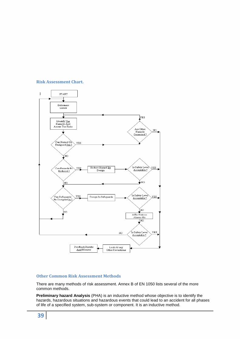
Risk Assessment Chart.
Other Common Risk Assessment Methods
There are many methods of risk assessment. Annex B of EN 1050 lists several of the more common methods.
Preliminary hazard Analysis (PHA) is an inductive method whose objective is to identify the hazards, hazardous situations and hazardous events that could lead to an accident for all phases of life of a specified system, sub-system or component. It is an inductive method.

40
‘What-if’ is another inductive method. For simple applications, the machine’s design, operation and use are reviewed. ‘What-if’ questions are formulated at each step and answered to evaluate the effect of failures or errors. In more complex applications, ‘What-if’ can be applied by using a checklist.
Failure Mode and Effects Analysis (FMEA) is an inductive method whose main purpose is to evaluate the consequences and frequency of component failure. If operator error or operating procedures are more significant, other methods are likely to be more suitable.
Fault Simulation for Control Systems is an inductive method with test procedures based on two criteria: technology and the complexity of the control system. In general the following are applicable: practical tests on the actual circuit and simulated faults on the component; and a simulation of control behavior either by hardware and/or software methods.
MOSAR (Method organised for a Systematic Analysis of Risks) is a complete approach made up of 10 steps. The system to be analysed is looked at as several sub-systems which interact. Hazards, hazardous situations and hazardous events are identified in a table.
Fault Tree Analysis (FTA) is a deductive method carried out from an event that is considered to be unwanted. This enables the user to find the whole set of critical paths that leads to the unwanted event. It is specified in IEC 1025 fault Tree Analysis.
The DELPHI technique questions a large circle of experts in several steps, where the result of the previous step with additional information is communicated to all participants. It is a forecasting method, often used in idea generation.
Inductive
Deductive
Hazard Identification
A hazard is:-
Anything that has the potential to do harm, a source of possible injury or damage to health.
A risk is:-
The likelihood of someone coming into contact with a hazard and the degree of injury or damage to health that could be caused should contact occur.
A hazardous situation is: -
Any situation where a person or persons are exposed to a hazard.
Examples
A moving belt on a conveyor would be a hazard. The risk would be the likelihood of someone coming into contact with an in-running nip or being drawn along the belt by a protrusion and the severity of injury or damage to health that could be caused.
An electrical enclosure containing voltages above 50v AC and 60v DC that has uncovered terminations is a hazard even though the enclosure may be kept locked and strict key control enforced. The reason for this is that if an electrician had to carry out diagnostic testing on a live enclosure they could inadvertently touch an adjacent terminal with a tool etc. The risk would be the likelihood of that happening and the severity of injury or damage to health that could be caused.

41
Common Hazard Categories
1. Mechanical hazards.
2. Electrical hazards.
3. Thermal hazards.
4. Hazards generated by noise.
5. Hazards generated by vibration.
6. Hazards generated by radiation.
7. Hazards generated by materials and substances (and their constituent elements) processed or used by the machinery.
8. Hazards generated by neglecting ergonomic principles in machinery design.
9. Combination of above hazards.
10. Unexpected start-up or over-run/over-speed (or any similar malfunction).
11. Impossibility of stopping a machine in the best possible conditions.
12. Variations in the rotational speed of tools.
13. Failure of the power supple.
14. Failure of the control circuits.
15. Errors of fitting.
16. Break-up during operation.
17. Falling of ejected objects of fluids.
18. Loss of stability / overturning of machinery.
19. Slip, trip and fall of person (related to machinery).
20. Additional hazards, hazardous situation and hazardous events due to mobility.
21. Hazards linked to the work position (including driving station) of the machine.
22. Hazards due to the control system.
23. Hazards from handling the machine (lack of stability).
24. Hazards due to the power source and to the transmission of power.
25. Hazards from / to third persons.
26. Hazards. Hazardous situation and hazardous events due to lifting.
27. Hazards, hazardous situations and hazardous events due to the lifting or moving of persons.

42
Preliminary Hazard Analysis using Hazard Rating Number System
With this method you are asked to assign numerical values to phrases relating to the:
Likelihood of Occurrence (LO)
Frequency of Exposure (FE)
Degree of Possible Harm (DPH)
Number of People at risk at any one time (NP)
Likelihood of Occurrence : The chances of a person(s) coming into contact with the hazard or being in a situation that they are exposed to a hazard.
Frequency of Exposure: How often are person(s) exposed to a hazard?
Degree of Possible Harm: The maximum degree of injury or damage to health that could be caused.
Number of People at risk at any one time: The number of people that are exposed to the hazard at any one time.
Firstly, the hazard has to be identified. Using the following table and knowledge of how the machine operates, the likelihood of a person or persons coming into contact with the hazard has to be decided and the relevant numerical value from the chart allocated.
When this decision is made the same thought process is used to determine the frequency of exposure to the hazard, the degree of injury or damage to health that could be caused should the person or persons come into contact with the hazard and how many people are exposed to the hazard at any one time.
The next step is to multiply all the numbers together to give the hazard rating number (HRN). From this and using the table shown on the next page, the degree of risk from negligible to unacceptable can be determined.
When carrying out a risk assessment on machinery that has existing control measures, for example guards, light curtains, pressure mats, interlocks e tc , these control measures should be disregarded for the purposes of risk assessment only. The reason for this is that after carrying out the initial assessment the existing control measures can be introduced and a re-assessment completed to ascertain whether or not the control measures are adequate and reduce the risk to an acceptable level.
43
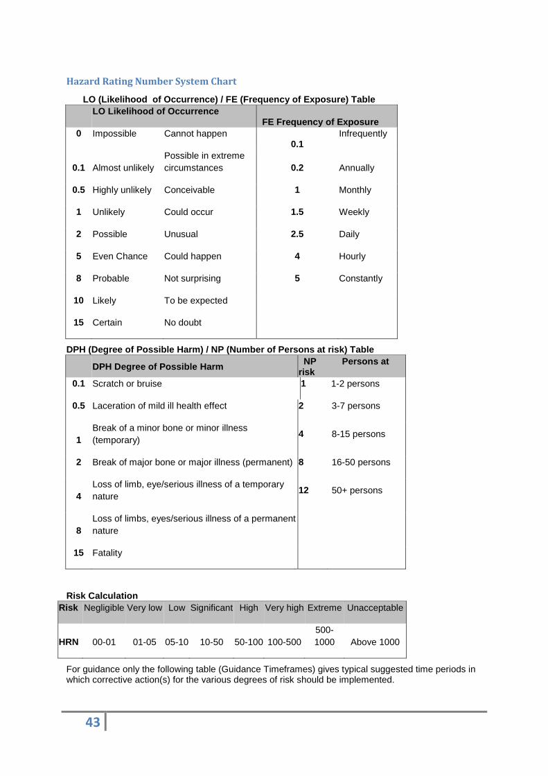
Hazard Rating Number System Chart
LO (Likelihood of Occurrence) / FE (Frequency of E xposure) Table LO Likelihood of Occurrence
FE Frequency of Exposure 0 Impossible Cannot happen
0.1 Infrequently
0.1 Almost unlikely Possible in extreme circumstances 0.2 Annually
0.5 Highly unlikely Conceivable 1 Monthly
1 Unlikely Could occur 1.5 Weekly
2 Possible Unusual 2.5 Daily
5 Even Chance Could happen 4 Hourly
8 Probable Not surprising 5 Constantly
10 Likely To be expected
15 Certain No doubt
DPH (Degree of Possible Harm) / NP (Number of Perso ns at risk) Table DPH Degree of Possible Harm NP Persons at
risk 0.1 Scratch or bruise 1 1-2 persons
0.5 Laceration of mild ill health effect 2 3-7 persons
1 Break of a minor bone or minor illness (temporary)
4 8-15 persons
2 Break of major bone or major illness (permanent) 8 16-50 persons
4 Loss of limb, eye/serious illness of a temporary nature
12 50+ persons
8 Loss of limbs, eyes/serious illness of a permanent nature
15 Fatality
Risk Calculation Risk Negligible Very low Low Significant High Very high Extreme Unacceptable
HRN 00-01 01-05 05-10 10-50 50-100 100-500 500-1000 Above 1000
For guidance only the following table (Guidance Timeframes) gives typical suggested time periods in which corrective action(s) for the various degrees of risk should be implemented.
44
Guidance Timeframes
Risk Negligible Very low Low Significant High Very high Extreme Unacceptable
Time Accept risk < 1 year < 3 months < 1 month < 1 week < 1 day Immediate Stop activity
Control Measures
The Hierarchy of Control Measures
When the hazard has been identified and the risk assessed, the next activity is to reduce the level of risk to the lowest level that, in the opinion of the assessor(s), is possible. This however, must be done in a structured manner. The recognised hierarchy of control measures is: -
1. Eliminate or reduce the hazard; that is design it out or remove it if reasonably practicable, if not then-
2. Eliminate the need for persons to be exposed; that is remove the need for operator intervention if possible, if not then-
3. Use guards; that are physical or non-physical electronic barriers between persons and the hazard if possible, if not then.
4. Reduce the probability of occurrence by altering the task, the method used or the use of jigs, holders, push sticks etc. If not then-
5. Reduce the degree of harm; that is by reducing the area of the hazard that can do harm or slow down the speed of approach of the hazard or use different components that present a lower degree of harm; the provision of personnel protective clothing, if not then-
6. Warn and inform (only if adequate safety can be achieved by these measures); that is warning notices, training, information for safe use, etc.
Risk Assessment Example
Risk of Injury due to the present guarding, partially fitted, allowing access to the moving parts. L.O. F.E. D.P.H. N.P. = H.R.N.
2 X 5 X 4 X 1 = 40 Degree of risk: = Significant
Clearly from this example we can see that the existing guarding, whilst offering a certain amount of protection, is not adequate and the degree of risk can be reduced further by fitting a guard that completely prevents contact with the hazard but does not affect the production.
Control Measure:
Fit a tunnel guard that complies with relevant standards for guarding and safety distances, and prevents all access to the moving parts.
After control measures fitted: L.O. F.E. D.P.H. N.P. = H.R.N.
0.1 X 0.1 X 4 X 1 = 0.04
Degree of risk: = Negligible

45
46
Glossary of Terms
European Commission
A representative committee of member state governments who steer the legislation of the European Union.
European Economic Area
Members of the European Union who want to harmonise their industrial practices to promote cross-border trade.
Countries in the EEA as of August 2001:
Austria
Belgium
Denmark
Finland
France
Germany
Greece
Iceland
Ireland
Italy
Liechtenstein
Luxembourg
Netherlands
Norway
Portugal
Spain
Sweden
United Kingdom
PUWER
Provision and Use of Work Equipment Regulations, updated in Britain in 1998. (PUWER 98).