m profil 3.11 en referencemanual
TRANSCRIPT

The M-PROFIL software system is a program intended for semi-automatic design of Profi Plus system low-voltage distribution boards, XVTL and xEnergy stand-alone distribution boxes, Global-Line,xBoard compact distribution boxes fitted with Eaton equipment.
M-PROFIL 3.11 REFERENCE MANUAL

_______________________________________________________________________________
_______________________________________________________________________________________________________________________
_____________________________________________________________________________ M-PROFIL version 3.11, Reference manual © Ing. Petr Slavata, 1996-2011 Translation: Agentura ProLingua s.r.o., Czech Republic Exclusive rights: Eaton Elektrotechnika s.r.o. Komárovská 2406, 193 00 Praha, Czech Republic Technical assistance (Czech Republic): Eaton Elektrotechnika s.r.o. Komárovská 2406, 193 00 Praha, Czech Republic tel: +420 267 990 411, fax: +420 267 990 419 e-mail: [email protected] http://mprofil.moeller.cz www.EatonElektrotechnika.cz
This documentation is an integral part of the M-PROFIL software system and may be distributed only in connection with this system. The author provides the software system and its documentation on an „As-is“ basis without warranties of any kind and with the potential occurrence of faults. The author shall not be held liable for any deliberate, indirect, incidental or subsequent damage arising in connection with the use of these materials. This manual describes the status of the software system at the time upon completion of its development and does not concern any potential changes in the future. All registered trademarks or other trademarks used in this documentation are the property of their respective owners. No ownership rights arising therefrom are questioned by their reference in the documentation. Files: M-PROFIL_TI.DOC, M-PROFIL_OB.DOC, M-PROFIL_**.DOC where ** is 01 - 11

_______________________________________________________________________________
_______________________________________________________________________________________________________________________
M-PROFIL, Reference Manual I
CONTENTS _______________________________________________ M-PROFIL_OB.DOC
Contents ...................................................................................................................................... I M-PROFIL_01.DOC
1. Introduction ............................................................................................................................. 1
2. Installation ............................................................................................................................... 5 2.1 Installation from CD-ROM ....................................................................................... 5 2.2 Manual customer installation in case of SETUP failure ........................................... 7 2.3 Installation backup .................................................................................................... 8 2.4 Updating Software from the Website ........................................................................ 9 2.5 Updating Software from the directory ...................................................................... 9
3. Launching M-PROFIL .......................................................................................................... 10 3.1 First launching ......................................................................................................... 10 3.2 Second and any other launching ............................................................................. 11 M-PROFIL_02.DOC
4. Introduction to the M-PROFIL System ................................................................................ 13 4.1 Main screen and program operation ........................................................................ 13 4.2 Undo, Redo ............................................................................................................. 14 4.3 Method of program application ............................................................................... 15
5. Project Structure Management .............................................................................................. 17 5.1 Add a new distribution board to the project ............................................................ 18 5.2 Create a new distribution board by copying the selected one ................................. 18 5.3 Add switchgear drawing into the project ................................................................ 18 5.4 Rename the selected distribution board .................................................................. 18 5.5 Number of pieces of the distribution board in a project ......................................... 19 5.6 Erase the selected distribution board from the project ............................................ 19 5.7 Insert distribution boards from another project ....................................................... 19 5.8 Change the distribution board position in the project structure tree ....................... 19 5.9 Information about the type of the edited distribution board ................................... 20 5.10 Switch frame/door view ........................................................................................ 20 M-PROFIL_03.DOC
6. Compact Distribution Box .................................................................................................... 22 M-PROFIL_04a.DOC
7. Profi Plus Distribution Boards (User-Defined Assemblies) ................................................. 26 8. Profi Plus Distribution Boards (Typical Assemblies) ........................................................... 34 M-PROFIL_04b.DOC
9. Stand-alone Distribution Boxes ............................................................................................ 38 9.1 XVTL stand-alone distribution boxes ..................................................................... 38 9.2 xEnergy distribution boxes ..................................................................................... 46 9.3 Drawing a switchgear .............................................................................................. 53 M-PROFIL_05a.DOC
10. Mounting Rails .................................................................................................................. 57 10.1 Inserting mounting rails, method A) - automatic fitting ....................................... 61 10.2 Inserting mounting rails, method B) - inserting individual rails ........................... 62 10.3 Inserting supports and mounting plates into XVTL stand-alone distrib. boxes .... 63 10.4 Inserting a SASY busbar system into the XVTL stand-alone distrib. boxes ........ 65 10.5 Inserting device modules in the xEnergy stand-alone distribution boxes (outgoer section) ................................................................................................... 69

_______________________________________________________________________________
_______________________________________________________________________________________________________________________
II M-PROFIL, Reference Manual
10.6 Inserting rails and mounting plates in the xEnergy stand-alone distrib. boxes (universal sections) ...............................................................................................70 10.7 Editing a mounting rail (change in type, depth, height)........................................71 10.8 Erasing a mounting rail .........................................................................................72 M-PROFIL_05b.DOC
11. Electric Meter Troughs .......................................................................................................73 11.1 Inserting an electric meter trough .........................................................................73 11.2 Editing an electric meter trough............................................................................76 11.3 Erasing an electric meter trough ...........................................................................76 M-PROFIL_06.DOC
12. Cover Plates ..................................................................................................................77 12.1 Inserting cover plates, method A) - automatic fitting ...........................................77 12.2 Inserting cover plates, method B) - inserting individual plates ............................78 12.3 Editing a cover plate (change in type, height or position on the frame) ...............81
12.4 Erasing a cover plate .............................................................................................81
13. Blind Flanges ..................................................................................................................82 13.1 Inserting blind flanges, method A) - automatic fitting..........................................82 13.2 Inserting blind flanges, method B) - inserting individual pieces in the list ..........83 13.3 Fitting a blind flange from the list into the cover plate cutout..............................85 13.4 Removing a blind flange from cover plate cutout.................................................86 13.5 Erasing a blind flange from the list .......................................................................87 M-PROFIL_07.DOC
14. Cable Ducts ..................................................................................................................88 14.1 Working with the cable ducts database.................................................................88 14.2 Inserting a horizontal cable duct from the database in the distribution board ......91 14.3 Inserting a vertical cable duct from the database in the distribution board ..........94 14.4 Erasing a cable duct ..............................................................................................97 M-PROFIL_08.DOC
15. Fitting Distribution Boards with Devices ...........................................................................98 15.1 Database of Moeller devices .................................................................................98 15.1.1 Command and signalling devices fitted on the door...................102 15.2 Database of third-party devices (devices from other manufacturers) .................104 15.2.1 Working with the database of third-party devices ...............................105 15.2.2 Inserting a third-party device in the list ...............................................110 15.3 Inserting terminal blocks.....................................................................................111 15.3.1 Working with the terminal block database...........................................111 15.3.2 Inserting a selected predefined terminal block in the list.....................114 15.4 Inserting N/PE terminals (connecting and branching sleeves) ...........................115 15.5 Loading the list of devices and accessories from a wiring diagram ...................115 15.5.1 Structure of the file containing the list of devices and accessories ensuring the interconnection with the wiring diagram drawing sw. ....119 15.6 Working with the list of the selected devices .....................................................121 15.7 Editing tags..........................................................................................................123 15.8 Changing the device quantity in the list of the selected devices.........................123 15.9 Erasing a device from the list of the selected devices.........................................124 15.10 Continuous test of the devices to be fitted on the distribution board rails........124 15.11 Fitting devices on distribution board rails/door ................................................125 15.11.1 AutoFit devices on distribution board rails/door ...............................125 15.11.2 Fitting the selected device on distribution board rails/door ...............128 15.11.3 Removing a fitted device from rail/door ............................................130 15.11.4 Moving a fitted device from one rail to another.................................130 15.11.5 Moving a fitted device........................................................................132

_______________________________________________________________________________
_______________________________________________________________________________________________________________________
M-PROFIL, Reference Manual III
M-PROFIL_09a.DOC
16. Free Graphics ................................................................................................................134 16.1 Displaying the Free Graphics toolbar .................................................................134 16.2 Setting the layer for newly inserted free graphics...............................................134 16.3 Line ................................................................................................................134 16.4 Rectangle.............................................................................................................135 16.5 Circle ................................................................................................................135 16.6 Text ................................................................................................................135 16.7 Drawing tools ......................................................................................................136 16.7.1 Setting Grid, Snap, turning on the indication of coordinates ...............136 16.8 Editing the properties of the free graphics components......................................137 16.9 Changing the position of components.................................................................138 16.10 Copying components.........................................................................................139 16.11 Changing the component geometry - Stretch....................................................140 16.12 Erasing components ..........................................................................................141 M-PROFIL_09b.DOC
17. Accessories ................................................................................................................142 17.1 Database of Moeller accessories .........................................................................142
17.2 Database of third-party accessories.....................................................................144 17.3 Changing the accessories quantity in the list ......................................................148 17.4 Erasing accessories from the list .........................................................................148
M-PROFIL_10aDOC
18. Searching Components in Data Structures .......................................................................149
19. Checking Temperature Rise in Distribution Boards.........................................................151 19.1 Checking the temperature rise in compact distribution boxes ............................151 19.2 Checking the temperature rise in distribution boards .........................................153 M-PROFIL_10b.DOC
20. Information about Project, Title Block .............................................................................160
21. Breakdown List of Components .......................................................................................161 21.1 Preview of the breakdown list of components ....................................................161 21.2 Printing the breakdown list of components to printer.........................................163 21.3 Exporting the breakdown list ..............................................................................163 21.4 Calculating the total project price .......................................................................165 21.5 Discount and surcharge settings..........................................................................166 21.6 Distribution board weight calculation.................................................................170
22. Dimensional Drawing .......................................................................................................171 22.1 Preview of the distribution board dimensional drawing .....................................171 22.2 Printing the distribution board dimensional drawing..........................................172 22.3 Exporting the distribution-board dimensional drawing ......................................173 M-PROFIL_11a.DOC
23. View Control (Zoom)........................................................................................................175 23.1 Regenerating images ...........................................................................................175 23.2 Pan……...............................................................................................................175 23.3 Zoom in/zoom out ...............................................................................................176 23.4 Zooming in a part of the design (Zoom Window) ..............................................176 23.5 Return to the previous image (Zoom Previous) ..................................................177 23.6 Viewing the distribution board image (Zoom All) .............................................177
24. Geometric Tools ................................................................................................................178 24.1 Distance measurement ........................................................................................178 24.2 Determination of point coordinates.....................................................................178

_______________________________________________________________________________
_______________________________________________________________________________________________________________________
IV M-PROFIL, Reference Manual
25. Working with Files ...........................................................................................................179 25.1 Saving your distribution board design to a file on the disk ................................179 25.2 Loading (opening) a file with distribution board design.....................................180 25.3 Editing a new distribution board .........................................................................181 25.4 Ending the program session ................................................................................182
26. Options…………..............................................................................................................183 26.1 Setting the breakdown list generation algorithm ................................................183 26.2 Print settings........................................................................................................185 26.3 Changing the licence data ...................................................................................188 26.4 Price list - currency and exchange rate ...............................................................189 26.5 Distribution Boards .............................................................................................189 26.6 System settings....................................................................................................190 26.7 Export to DXF file format...................................................................................192
27. Help……………...............................................................................................................194 27.1 Tip of the Day .....................................................................................................194
28. About M-PROFIL.............................................................................................................195 M-PROFIL_11b.DOC
29. History of Versions ...........................................................................................................196

_______________________________________________________________________________
_______________________________________________________________________________________________________________________
M-PROFIL, Reference Manual 1
1. Introduction _______________________________________________ The M-PROFIL software system is a program intended for semi-automatic design of Profi Plus system low-voltage distribution boards, XVTL, xEnergy stand-alone distribution boxes and Global-Line, Xboard compact distribution boxes fitted with Eaton/Moeller equipment. Software facilitates the design of the distribution board and selection of devices from the database, checks the dimensional consistence of the individual parts and generates the breakdown list. It is an independent program requiring only the operating system of Windows. The software is intended primarily for dealers, designers and computational engineers. The system allows the following:
1. Design up to 50 distribution boards parallel within a single open project. 2. Design of Global-Line and Xboard compact distribution boxes, as follows: The compact
distribution box is to be selected from the options tree (the specified number of the modules is to be taken into account); photographs and dimensional drawings are available.
3. Design of Profi Plus distribution boards: specification of the distribution board characteristics (position, degree of protection, fire resistance, design version) and dimensions; the selected dimensions are checked for suitability based on the number of modules and number of el. meter troughs.
4. Option to select standard assemblies (typical Profi Plus distribution boxes available as intermediate products, which can be edited).
5. Design of XVTL type stand-alone distribution boxes with a height of 2000 mm; comprehensive designing of the interior configuration.
6. Design of xEnergy series stand-alone distribution boxes with a height of 2000 mm (type-tested distribution boxes up to 4000A); comprehensive designing of the interior configuration.
7. For all the distribution systems, the distribution box front view and profile drawing are drawn with a scale of 1:1 (with the option, at a later time, to use a different, more suitable scale for printing).
8. For stand-alone distribution boxes, there is the option of drawing the switchgear (a set of distribution box sections that are situated side by side); there is the check of consistent interactions of the adjoining sections. The front view and ground plan are drawn.
9. Selection of devices from database. The selected device is inserted in the list and can be subsequently fitted into the distribution board (the rail type, installation depth, collision with other devices on the rail etc. are checked when fitting the device). A special function is available for creation and editing of RMQ-series command and signalling device assemblies; these devices are fitted on door.
10. Possibility to insert a third-party device is provided (i.e. a device from a supplier other than Eaton/Moeller), box with dimensions and data about the device, which is not included in the database. The user can create its own database of third-party devices step by step.
11. Possibility to insert a terminal block is provided, i.e. a third-party device with special shape. A simplified shape of the terminal block is drawn based on the specified data. The user can create its own database of terminal blocks step by step.
12. Possibility to insert interconnecting and branching bridges (N/PE terminals). The bridge is built interactively from the particular components and can be inserted in the list and then fitted into the distribution board.

_______________________________________________________________________________
_______________________________________________________________________________________________________________________
2 M-PROFIL, Reference manual
13. Possibility to create a list of devices and accessories by loading a standard-form data file. This file can be generated by wiring diagrams drawing software (at present e.g. by ElproCAD from Astra92 a.s. Zlín, Czech Republic), ordering systems, or manually using Microsoft Excel.
14. Possibility to insert free graphics – line, rectangle, circle, text (on the distribution-board frame or door); possibility to edit the graphics subsequently by means of standard functions (Copy, Move, Stretch, Erase). The standard grid and snap tools are available.
15. Possibility to search for components in the system data structures based on type designation. It is also possible to enter only a partial string, and the system finds all corresponding components. The components found can be inserted in the lists.
16. Devices from the list can be automatically fitted into the distribution board in the suitable order (the rail type, installation depth, collision with other devices on the rail and place on the rail are checked when fitting the device). A schematic front view of the device will be drawn. The command and signalling devices are fitted on the distribution board door; other devices are fitted on DIN rails, busbars and mounting plates.
17. Each fitted device can be marked with tag - an alphanumeric code ensuring its link to the electric wiring diagram.
18. It is possible to change the position of the fitted devices (in the graphics). The suitable rail type, installation depth, place on the rail, position on the door etc. are check at the same time. Possibility to move groups of devices. Possibility to change the rails.
19. Additional change of the distribution board is possible based on the actual number of devices. Possibility to change non-geometric parameters of the distribution board without the need to delete any linked components such as mounting rails or cover plates. Unless you change the distribution board system or dimensions of the distribution board, the linked components remain unchanged.
20. It is possible to choose accessories for devices as well as mechanical components of the distribution board arbitrarily from the database according to the catalogue options. It is possible to insert third-party accessories (i.e. accessories from a supplier other than Eaton/Moeller). The user can create its own database of third-party accessories step by step. Intangible “price” items can also be defined as third-party accessories; they will appear only in the breakdown list (such as extra charge for frame mounting etc.).
21. Selection of mounting rails - selection of the rail type, specification of the rail depth and height in numbers, type of the connectors and the base type. The rail will be drawn schematically in the specified position. A check is carried out whether the rail is placed in the frame and whether any collision between the rails (electric meter troughs) occurs.
22. Selection and insertion of supports, mounting plates and busbar systems in the XVTL stand-alone distribution boxes. Complex design of the internal configuration in the XVTL stand-alone distribution boxes.
23. Insertion of SASY busbar systems. 24. For xEnergy series distribution boxes: The outgoer section can be fitted with device modules.
Universal sections can be fitted with mounting plates. Comprehensive designing of the interior configuration.
25. Selection of electric meter troughs and their insertion into the distribution board; check for collision with other components.
26. Insertion of cable ducts. The user can create its own database of cable ducts step by step (Eaton/Moeller do not have cable ducts in their offer).
27. Selection of cover plates and blind flanges; possibility for their automatic fitting into the distribution board.
28. Calculation of temperature rise in distribution boards. For Global-Line and Xboard compact distribution boxes, a check is carried out as to whether the power losses of the fitted devices

_______________________________________________________________________________
_______________________________________________________________________________________________________________________
M-PROFIL, Reference Manual 3
do not exceed the maximum value defined by the manufacturer. Calculation of the temperature rise is performed for Profi Plus distribution boards and XVTL and xEnergy stand-alone distribution boxes in accordance with IEC 890+A1.
29. Generation of the breakdown list. The catalogue price (for Eaton/Moeller components) or the entered price (for other components from different suppliers) is specified for each component in the breakdown list. All components are divided into groups. A discount or surcharge can be entered for each group in percentage rate. The price of every component is then determined as follows: PurchasePrice = CataloguePrice - CataloguePrice * Discount / 100 Price = PurchasePrice + PurchasePrice * Surcharge / 100 In case the user does not require such detailed price calculation, it is possible to activate a mode in which the price of every component is multiplied by a user-defined price coefficient taking into account e.g. the supplier's discount. The total price of the distribution board is calculated. The generating algorithm of the breakdown list (rounding of the number of pieces etc.) and data specified in the breakdown list can be modified.
30. Distribution board weight calculation. 31. Print of the distribution board front view with the fitted devices, with mounted cover plates;
print of its side view - rail depths. The main dimensions of the distribution board are quoted. The position of rails is defined by means of installation information specified for every rail. Alternatively, it is possible to view and print the distribution board frame (rails, devices, cover plates, blind flanges, the door (including the fitted command and signalling devices), and the main busbars (for XVTL and xEnergy distribution boxes). Possibility to set the line thickness for printing. Possibility to print in fixed scale defined by the user (e.g. 1:10), or in the automatically determined scale (max. to page).
32. Export of graphics to DXF was added (universal exchangeable format for CAD systems). 33. Print of the breakdown list. 34. Export of the breakdown list to files of various formats with the possibility to work further
with the breakdown list in standard text and spreadsheet processors (Excel). 35. The component breakdown list can be exported to Excel either in the M-PROFIL standard
format or in the format according to the Eaton/Moeller Price List application. 36. Export of the component breakdown list in the format for the SAP system. 37. Project archiving. All information is saved in a single data file. 38. Manual and help.
Not required and not possible with the system:
1. Check and selection of devices based on electrical parameters. 2. Interconnection of devices, drawing of conductors, table of conductors, table of connections
and terminals. 3. Checking of links between a device and the accessories. 4. Wiring diagram drawing.
Hardware and software requirements (the minimum configuration is as follows):
PC, Pentium III and higher, 32 MB and more RAM (64 MB recommended), graphics with the minimum resolution of 800x600 (1024x768 recommended), 15” and larger screen, mouse or other pointer/indicating device, output printing device for A4 paper format.
At least 200 MB free hard-disk space. Operating system installed - Windows95 and higher or WindowsNT 4.0 or Windows2000
Professional (ServicePack1 installed), WindowsXP, or WindowsVista.

_______________________________________________________________________________
_______________________________________________________________________________________________________________________
4 M-PROFIL, Reference manual
Notes: The M-PROFIL software is not a network program. It must always be installed on the local
disk of every user. The licence to use the program system is provided for a limited period of time. The licence is
provided by Eaton Elektrotechnika s.r.o., the exclusive holder of rights to the program.

_______________________________________________________________________________
_______________________________________________________________________________________________________________________
M-PROFIL, Reference Manual 5
2. Installation _______________________________________________
2.1 Installation from CD-ROM 1. Insert the installation CD disc in the drive (e.g. in the D: drive). 2. Run the \M-PROFIL_SETUP\SETUP.EXE program from the CD disc. Click on the Start
button and select the item Run. Type the following text into the item Open of the dialogue panel that opens up subsequently: D:\M-PROFIL_SETUP\SETUP.EXE (letter D is the CD drive identification). Or, use the Browse button. Click on the OK button.
3. Select the language version of the installation from the list of the options being offered.
4. Now, you are prompted to close all the running applications (programs). It is also
recommended that the network drivers and antivirus programs running in the background should be disconnected. After clicking Next continue the installation.
5. Read the Licence Agreement in the dialogue panel that opens up subsequently. If you agree
with the conditions, select the option ‘I agree’. Then click Next.

_______________________________________________________________________________
_______________________________________________________________________________________________________________________
6 M-PROFIL, Reference manual
6. Now, specify the directory INTO which the program is to be installed. The M-PROFIL is not a
network program. It must always be installed on each user’s local disc. If the preset directory is not convenient, click on the Browse button and specify a different directory in the dialogue panel that opens up subsequently. After clicking Next, continue the installation.
7. If there is already an older version of the M-PROFIL program in the specified destination directory, the system asks if the files that have been modified by the user are to be transferred from the previous installation. After clicking Next continue the installation.
The default directory that the program is to be installed in. You can change it by editing the text. Or, you can select the directory after clicking on the Browse button. If the directory already exists, you will be prompted to confirm the right selection. The program cannot be installed directly into the root directory of the hard disc drive or into the system directory. After selecting the directory, click on the Next button to continue the installation.
If you agree with the terms of the Licence Agreement, click on ‘I accept…’ to accept them. Then continue the installation by clicking on the button Next.
If the user-defined database of devices, terminal blocks, cable ducts and accessories of other manufacturers has been modified in the previous installation, click on this button. If you are not sure, use this button as well.
The original installation will be deleted; the user-defined database of devices, terminal blocks, cable ducts and accessories of other manufacturers will not be transferred.

_______________________________________________________________________________
_______________________________________________________________________________________________________________________
M-PROFIL, Reference Manual 7
Please, pay attention to the following warning:
8. Specify the name of the program group that the program’s icon will be inserted in (a new item
name at the Start – Programs menu). It is recommended that the default name should be kept. After clicking Next continue the installation.
9. The setting carried out in the previous steps is summarized at the sheet that is displayed
subsequently. Please, check if the setting meets your requirements. By means of the Back button, you can reverse the necessary number of steps and modify the individual parameters. The actual installation is to be launched by clicking on the Install button.
10. Now, the files will be copied to the hard drive of the computer, and the installation will be expanded.
11. A final report will be displayed by the installation program. This means that the installation has been completed in a correct way and the M-PROFIL program is ready for use. Close this dialogue panel by clicking on the Finish button. The installation program will automatically create the ‘run’ icon on the desktop, and will carry out the association of the .FGP files (projects of distribution boards) with the M-PROFIL program (the program will be automatically activated after you double click on the file with the FGP extension in the Windows Explorer). Run the program and enter the licence (see Chap. 3.1).
12. The program installed can be removed by means of the uninstall program. Click on the Start button, then subsequently select the items Programs - M-PROFIL - Uninstall. The uninstall program will start, and the installation will be removed from your computer.
2.2 Manual customer installation in case of SETUP failure A problem may occur on some computers when installing M-PROFIL from the installation CD-ROM through the standard procedure with SETUP.EXE. As an alternative solution, it is possible to install the software “manually” without using the installation program.
List of the existing program groups (items of the ‘Start – Programs’ menu)
Name of the newly created program group (an item of the ‘Start – Programs’ menu) that the program’s icon will be inserted in.

_______________________________________________________________________________
_______________________________________________________________________________________________________________________
8 M-PROFIL, Reference manual
Caution: performance of the manual installation requires certain knowledge and skills in computer operations. Should some steps from the procedure specified below be not completely clear or comprehensible to you, please leave the installation up to your system administrator or up to an expert in this field.
1. Create the directory C:\M-PROFILon your hard disk (using the operating system tools, such as the Windows Explorer, Total Commander etc.).
2. Copy all files from the directory \M-PROFIL\CUSTOM located on the installation CD-ROM into this newly created directory.
3. Run the program UnPack.BAT in the directory on your hard disk - the customer installation of the M-PROFIL program will be unpacked.
4. Create a shortcut icon for the M-PROFIL program on the desktop and a new item in the Start-Programs section (using the operating system tools).
5. Run the program by double-clicking the icon created in the previous step. If it is not possible to start the program, copy the files from the directory \M-PROFIL\WinSys on the installation CD-ROM to your Windows system directory, usually located at C:\Windows\System32 (Attention - newer versions of these libraries, which can already exist there in Windows, may not be overwritten !!).
6. Run the program and enter the licence data (see Chap. 3.1).
2.3 Installation backup Some files can be modified from time to time when using the program. This concerns files with the program configuration, user databases etc. It is desirable to back up these files:
File Comment From
version M-PROFIL\M-PROFIL.INI Program configuration 2.0 M-PROFIL\DATA\VLASTNI\... User database of third-party devices, terminal blocks, cable ducts and
accessories 3.0
Full installation backup: A precondition allowing you to perform the backup of the existing installation is the presence of the RAR.EXE packing program in the program root directory. RAR is not included in the standard installation, however, it is a shareware which can be downloaded from the Internet (e.g. at WWW.RARLAB.COM) and used further upon payment of the copyright fee.
1. Copy RAR.EXE to the superstructure root directory (typically C:\M-PROFIL). 2. Run Pack.BAT from the program root directory (typically C:\M-PROFIL). Click on the
Start button and select Run. A dialogue panel will open, in which you type the following text in the Open field: C:\M-PROFIL\Pack.BAT (where C:\M-PROFIL is the path to the program root directory). Click OK.
3. The program will be packed. Archive file M-PROFIL.RAR will be created in the superstructure root directory. Make a back up of these files together with UNRAR.EXE and UnPack.BAT.
4. By using UnPack.BAT, you can unpack the archive files again.

_______________________________________________________________________________
_______________________________________________________________________________________________________________________
M-PROFIL, Reference Manual 9
2.4 Updating Software from the Website M-Profil also includes the so-called Updater, a program designed to check the availability of new software versions on the Eaton/Moeller website. The launch of this program is offered automatically at regular intervals when you start M-Profil. If the update launch is authorized by the user, the program will automatically connect to the Eaton/Moeller website and check the availability of any new version of M-Profil. If a new version is available, it will be downloaded and installed automatically. An Internet connection and settings your computer firewall are a pre-conditions for this function (please contact your IT manager). Notes:
The setting of the time interval to check the availability of new versions on the Eaton/Moeller website can be adjusted by means of the Options function under the System tab (see Chap. 26.6).
The date of the last check for the availability of new versions on the Eaton/Moeller website can be found using the Options function under the Licence tab (see Chap. 26.3).
Updater, the program designed to check the availability of new software versions on the Eaton/Moeller website, can be launched at any time by selecting Update Software from Website from the Help drop-down menu.
2.5 Software update from the directory If no Internet connection is available, it is possible to ask the software provider to have the update files sent in another way, and subsequently to update the software from directory.
1. Ask the software provider to have the update files sent to you, e.g. on a CD-ROM by postal service (there are two files for every update: control file *.XML and data file *.ZIP).
2. Load your update files to an auxiliary directory on the hard disk. All update files issued for the given software version must be present in the directory (it is not sufficient to have only the last issued update).
3. Launch M-Profil. 4. Select Software Update from Directory from the Help drop-
down menu. 5. A dialogue panel will subsequently open (similar to the Open
function), in which you select the update control file (with extension *.XML, file name is preset as default) and click Open.
6. M-Profil will be closed and Updater will be launched to update your installation.

_______________________________________________________________________________
_______________________________________________________________________________________________________________________
10 M-PROFIL, Reference manual
3. Launching M-PROFIL _______________________________________________
If you have installed M-PROFIL on your computer successfully in accordance with the procedure described in chapter 2, you can proceed with the program initialization.
3.1 First launching
1. Click the Start button and follow the menu according to the items Programs - M-PROFIL - M-PROFIL. If you have created a shortcut icon for the program at the desktop, you can simply run the program by double-clicking this icon.
2. A dialogue panel with the Licence Agreement text will be displayed.
If you agree with the text shown above, click the I Agree button. By doing so, you undertake to respect all provisions of the Licence Agreement. If you do not agree with the Licence Agreement, the program cannot be run. The wording of the Licence Agreement can be also viewed at any later point in time by using the function About M-PROFIL (see Chap. 28).
3. As the next step, a dialogue panel will open requesting the entry of licence data: Enter the required data specified in your licence or contact your software provider and ask him to provide you with the required licence data. Please pay special attention to filling out all items carefully, in particular the correct entry of licence expiration date and the licence number. The program will not be launched when incorrect values have been entered.

_______________________________________________________________________________
_______________________________________________________________________________________________________________________
M-PROFIL, Reference Manual 11
4. Provided everything was entered correctly, the program will now be launched - the Tip of the
Day window will be activated automatically showing the suggestions and recommendations for working with the program (for more details see Chap. 27.1). After reading the recommendation for this startup, please close the dialogue panel by clicking Close. The program is ready for use.
5. The system remembers the licence conditions and does not request their entry with another start of the program. The licence data can be changed additionally at a later point in time by using the Options function (see Chap. 26.3). You can also view the licence data by using the function About M-PROFIL (see Chap. 28).
3.2 Second and any other launching
1. Click the Start button and follow the menu according to the items Programs - M-PROFIL - M-PROFIL. If you have created a shortcut icon for the program at the desktop, you can simply run the program by double-clicking this icon.
2. The system checks the licence validity and, provided everything is correct, launches the program.
3. If the function for showing the tips of the day at startup is activated, the appropriate dialogue panel will appear. After reading the recommendation for this startup, please close the dialogue panel by clicking Close (for more details see Chap. 27.1). The program is ready for use.
Notes:
• For detailed description of the basic screen see Chap. 4.1. • For general procedure to be followed when using the program see Chap. 4.3. • If you want to continue in editing a distribution board design you have already created and
saved previously, open this file now by clicking the Open command from the File drop-down menu (see Chap. 25.2).

_______________________________________________________________________________
_______________________________________________________________________________________________________________________
12 M-PROFIL, Reference manual
• If the following message appears after the program startup:
It means that the software usability period has expired – the program can no longer be used. Download a new software version from the Internet and install it, or contact your M-PROFIL provider in order to obtain a new software version.
• If the following message appears after the program startup:
It means that your licence has expired. Please contact your provider of the M-PROFIL system and ask him to provide you a new licence number. Then click Yes and enter the new licence data in the dialogue panel identical to the one used during the first initialization (see Chap. 3.1).
• If the following message appears after the program startup:
It means that the file M-PROFIL.INI containing the licence data has been corrupted. Click Yes and enter the new licence data in the dialogue panel identical to the one used during the first initialization (see Chap. 3.1). If difficulties persist, contact your M-PROFIL system provider.

_______________________________________________________________________________
_______________________________________________________________________________________________________________________
M-PROFIL, Reference manual 13
4. Introduction to the M-PROFIL System _______________________________________________
4.1 Main screen and program operation After the program is started (see Chap. 3.1, 3.2), the program main screen is activated:
Drop-down menu with program functions
Information about the version and language version Currently opened file
Tools that serve for adjusting the program’s main window (minimize, maximize, close).
Toolbar with the icons of the main functions
Status line; information about the operation being performed.
The size of the window can be adjusted by dragging the edges.
Date and time
Status of the CapsLock and NumLock keys.
Project structure tree; up to 50 different distribution boards can be designed simultaneously within one project.
If the mouse pointer is moved to an icon, the description of the function is displayed.
Front view of the distribution board being edited (dimensional drawing with the rails and cover plates that are fitted with the devices and blind flanges).
Scroll bars for moving the view onto the drawing of the distribution board.
Description of the content of the clicked branch of the project structure tree. Switches for the drawing
tools, which make it easy to insert free graphics (see Chap. 16).
Cursor coordinates at the status line (this can be switched over by means of the F6 button; see Chap. 16.7).
Cursor in the form of an arrow or of a crosshair, depending on the program setting (see Chap. 26.6).

_______________________________________________________________________________
_______________________________________________________________________________________________________________________
14 M-PROFIL, Reference Manual
Double click any branch of the project structure tree to open the window containing the list of the selected components belonging to the respective branch (distribution board, devices, ...). Every window contains its own control elements allowing the user to modify the contents. Each separate window activated from the project structure tree can be operated in the same way as typically applied in Windows:
4.2 Undo, Redo The effect of all the program functions (except for the Zoom changes applied to the displayed image), as they were subsequently called, can be reverted by clicking on the Undo icon. The program retains in memory all the steps that have been carried out from the beginning of the project editing. Please, use the Undo function with caution because some operations are not visually apparent in a direct way. All the operations with the list of the selected elements, after the list was opened, are considered as one step. This is why the program asks the following query:
The effect of the last Undo function that has been carried out can be reverted by clicking on the Redo icon.
Control features to modify the window contents. Their number and function vary depending on the window type. Drag the edges, if you want to
modify the window size.
The window name specifies its contents. Close window (X) – also press Esc.
Drag the column partition to change its width.
Drag the blue band to change the window position.
Click on a line in the list to select the respective line – mark it for a certain editing operation. Several lines can be selected in some lists by dragging the mouse over the list (or by clicking the first line, pressing Shift and clicking on the last selection line).
‘Undo’ will not be carried out.
All the operations with the data table (with the list of the selected items) that have been carried out since opening the data table will be reversed.
Suppression of this warning message for the currently opened project

_______________________________________________________________________________
_______________________________________________________________________________________________________________________
M-PROFIL, Reference manual 15
4.3 Method of program application The M-PROFIL program is designed predominantly for trading and design businesses. Therefore it is conceived to be able to provide the customer with quick answers to the following questions:
• I need a distribution board, which can accommodate 150 modules. Give me a proposal of suitable dimensions and tell me what the price would be.
• I need a distribution board having specific dimensions and I need specific devices to be fitted in this distribution board. I need to know whether the given distribution board can accommodate these devices and what its price would be.
• I have a set of devices and I need to fit them into a distribution board. What components do I need to order?
• I want to order a specific distribution board. I need to create a breakdown list pieces and components, which will be necessary for its mounting.
There are several basic procedures provided for the design of the distribution board in the M-PROFIL system, which give answers to the questions mentioned above: Profi Plus distribution board, selection based on the dimensions:
1. The customer requests a specific size of the distribution board. First of all you select the suitable dimensions as required from the offered dimensional series of distribution boards for the given position and degree of protection (see Chap. 7).
2. You fit the mounting rails (Chap. 10) on the distribution board frame or insert the electric meter trough (Chap. 11), as the case may be.
3. Then you cover the distribution board frame with cover plates (see Chap. 12), thus obtaining the basic mechanical design of the distribution board. The Total Price function informs you about the total price of the design with respect to the current settings of discounts and surcharges (see Chap. 21.4, 21.5).
4. Such design can be supplemented with devices (to be fitted on the rails) - see Chap. 15, blind flanges - see Chap. 13 and other accessories as necessary - see Chap. 17.
5. The task ends with printout of the breakdown list and the dimensional drawing, see Chap. 21.2, 22.2.
Profi Plus distribution board, selection based on the devices:
1. The customer has a certain set of devices and needs them to be fitted into a suitable distribution board. You select devices from the device database (see Chap. 15.1), you can insert devices from other manufacturers (third-party devices) (see Chap. 15.2) or terminal blocks (see Chap. 15.3) and connecting sleeves (see Chap. 15.4). Then you add the required accessories to the devices (see Chap. 17).
2. Based on the dimensions of the selected devices, you design a suitable frame for the Profi Plus distribution board semi-automatically (see Chap. 7).
3. Then you fit the mounting rails (Chap. 10) on the distribution board frame or insert the electric meter trough (Chap. 11), as the case may be.
4. You fit the selected devices on the inserted rails (see Chap. 15.11). In case of any troubles, the fitting configuration on the rails or the frame dimensions can be changed.
5. Then you cover the distribution board frame with cover plates (see Chap. 12). The remaining cutouts in the cover plates will be covered with blind flanges (see Chap. 13), thus obtaining

_______________________________________________________________________________
_______________________________________________________________________________________________________________________
16 M-PROFIL, Reference Manual
the complete design of the distribution board. The Total Price function informs you about the total price of the design with respect to the current settings of discounts and surcharges (see Chap. 21.4, 21.5).
6. Check the temperature rise in the distribution board (see Chap. 19). 7. The Total Price function informs us about the total price of the design with respect to the
current settings of discounts and surcharges (see Chap. 22.4, 22.5). 8. The task ends with printout of the breakdown list and the dimensional drawing, see Chap. 21.2, 22.2.
Profi Plus distribution board, standard assemblies
1. The customer requires a typical distribution board specified through its dimensions and basic parameters (position, degree of protection, number of modules, number of electric meter points). Select the required type from the database of standard assemblies.
2. You obtain a “semi-finished” distribution board. If required, the internal configuration can be modified (change in the position of rails, cover plates, electric meter troughs, and possibility to insert new components).
3. The Total Price function informs you about the total price of the design with respect to the current settings of discounts and surcharges (see Chap. 21.4, 21.5).
4. Such design can be supplemented with devices (and a test can be carried out as to whether they can be fitted on the rails) - see Chap. 15, blind flanges - see Chap. 13 and other accessories as necessary - see Chap. 17.
5. The task ends with printout of the breakdown list and the dimensional drawing, see Chap. 21.2, 22.2. Global-Line, xBoard compact distribution box
1. The customer requires a compact distribution box fitted with certain devices. You select devices from the device database (see Chap. 15.1), you can insert devices from other manufacturers (third-party devices) (see Chap. 15.2) or terminal blocks (see Chap. 15.3) and connecting sleeves (see Chap. 15.4); (note: some compact distribution boxes already include the connecting sleeves as standard).
2. Based on the dimensions of the selected devices, you select the suitable compact distribution box with the required mechanical properties from the database (see Chap. 6).
3. The Total Price function informs you about the total price of the design with respect to the current settings of discounts and surcharges (see Chap. 21.4, 21.5).
4. You fit the selected devices on the compact distribution box rails (see Chap. 15.11). In case of any troubles, you can select a different compact distribution box.
5. Check the temperature rise in the distribution board (see Chap. 19). 6. The task ends with printout of the breakdown list and the dimensional drawing, see Chap. 21.2, 22.2.

_______________________________________________________________________________
_______________________________________________________________________________________________________________________
M-PROFIL, Reference manual 17
5. Project Structure Management _______________________________________________
A project represents a group of logically interrelated distribution boards, such as distribution boards on different floors in a single building etc. It is possible to design up to 50 distribution boards parallel within a single project. Every project must include at least one distribution board.
The project structure tree is shown in the left part of the basic program screen:
Operation of the project structure is possible by means of functions from the Distribution Board drop-down menu or by clicking on the respective icons in the tool bar. Right click on the tree branch to activate the Distribution Board context menu.
To roll the tree down (the sub-branches will appear) – click on the “+” sign. To roll the tree up (the sub-branches will be hidden) – click on the “-” sign.
Name of the distribution board in the project, the name specified by the user to identify the distribution board.
The selected distribution board in the project; a dimensional drawing is shown for this distribution board in the right part of the window.
No distribution board system has been defined yet for this distribution board, thus it is possible to work only with the lists of devices and accessories.
Distribution board of a compact distribution box type. Only blind flanges can be inserted in addition to devices and accessories.
Profi Plus distribution board. Rails, electric meter troughs, cable ducts cover plates and blind flanges can be inserted in addition to devices and accessories.
Description of contents of the clicked branch in the project structure tree.
Double click on the tree branch (or click once and press Enter) to open the window containing the list of the selected devices belonging to the respective branch (distribution board, devices, accessories, ...). Right click on the tree branch to show the Distribution Board context menu with functions for project structure modification.
Click on the tree branch to select the distribution board; if some distribution board system has already been defined, a dimensional drawing will appear in the window on the right.
Number of pieces of distribution board = number of repetitions of the same distribution board in project.

_______________________________________________________________________________
_______________________________________________________________________________________________________________________
18 M-PROFIL, Reference Manual
5.1 Add a new distribution board to the project
1. In the project structure tree, select the distribution board behind which you want to insert another one.
2. Select New from the Distribution Board drop-down menu or click on the icon Add new distribution board to project. A new item - a new distribution board - will be inserted in the project structure tree behind the selected branch. The new distribution board will be set as the current.
3. The distribution board has a standard default name Distribution Board + sequence number. This name identifying the distribution board in the project can be modified at a later point in time (see Chap. 5.4).
5.2 Create a new distribution board by copying the selected one
1. In the project structure tree, select the distribution board you want to copy. 2. Select Copy from the Distribution Board drop-down menu or click on the icon Create
new distribution board by copying the selected. A new item - copy of the selected distribution board - will be inserted in the project structure tree behind the selected branch. The complete and full definition of the distribution board is copied including the list of devices and accessories. The distribution board that has been copied will be set as the current.
3. The distribution board has a standard default name Copy + name of the original distribution board. This name identifying the distribution board in the project can be modified at a later point in time (see Chap. 5.4).
5.3 Add switchgear drawing into the project
1. In the project structure tree, select the distribution board behind which you want to insert the switchgear.
2. Select Switchgear from the Distribution Board drop-down menu or click on the icon Make switchgear drawing. A new item – switchgear – will be inserted in the project structure tree behind the selected branch. The new switchgear will be set as the current.
3. The switchgear has a standard default name of Switchgear + order number. This name identifying the distribution board in the project can be changed at a later point in time (see Chap. 5.4).
5.4 Rename the selected distribution board
1. In the project structure tree, select the distribution board you want to rename. 2. Select Rename from the Distribution Board drop-down menu or click on the icon
Rename the selected distribution board. A dialogue panel will open, in which you type the new name of the distribution board. This name identifies the respective distribution board in the project. Therefore, it must include at least one character and it should be a unique name within the project.

_______________________________________________________________________________
_______________________________________________________________________________________________________________________
M-PROFIL, Reference manual 19
5.5 Number of pieces of the distribution board in a project
1. In the project structure tree, select the distribution board that you want to set the number of pieces for.
2. Select the item Number of Pieces from the Distribution Board drop-down menu, or click on the icon Number of pieces for selected distribution board. Type the new number of pieces in the dialogue panel that opens up subsequently. The number of pieces represents the number of repetitions of the same distribution board within the framework of the project; the dimensional drawing is not drawn for individual pieces, and the breakdown list is made up according to the overall number of pieces. The default minimum value is 1.
5.6 Erase the selected distribution board from the project
1. In the project structure tree, select the distribution board you want to erase. 2. Select Erase from the Distribution Board drop-down menu or click on the icon Erase
the selected distribution board from the project. The program will ask you whether you are sure you want to erase the selected distribution board from the project. If you click Yes, the distribution board will be erased from the project including all linked components (devices, accessories). The effect of this function cannot be undone.
5.7 Insert distribution boards from another project
1. Select the item Insert from File in the Distribution Board drop-down menu.
2. A dialogue panel will open identical to the Open function (see Chap 25.2). Select the file with the project you want to insert in the currently opened project. Click on the Open button.
3. All distribution boards from the specified project will be inserted at the end of the currently opened project. The position of the individual distribution boards in the project structure tree can be subsequently modified (see Chap. 5.7). Only distribution boards from projects created in the current version can be inserted. If you wish to insert a distribution board from a project created in an older version, you must first open the project (see Chap. 25.2) and then save it in the format of the new version (see Chap. 25.1).
5.8 Change the distribution board position in the project structure tree
1. In the project structure tree, select the distribution board, the position of which you want to change. 2. Select Move Up from the Distribution Board drop-down menu or click on the icon
Move the distribution board upwards in the project structure. The selected distribution board will be moved one branch higher. You can move the distribution board all the way to the first position in the project structure by repeated activation of this function. If the selected distribution board is placed at the first position in the project structure, nothing will happen.
3. Select Move Down from the Distribution Board drop-down menu or click on the icon Move the distribution board downwards in the project structure. The selected

_______________________________________________________________________________
_______________________________________________________________________________________________________________________
20 M-PROFIL, Reference Manual
distribution board will be moved one branch lower. You can move the distribution board all the way to the last position in the project structure by repeated activation of this function. If the selected distribution board is placed at the last position in the project structure, nothing will happen.
5.9 Information about the type of the edited distribution board
1. In the project structure tree, select the distribution board to be edited. If the distribution board system has already been defined, a dimensional sketch is shown in the right part of the window.
2. Select Information about Type from the Distribution Board drop-down menu or click on the icon Information about the type of the edited distribution board. A dialogue panel with the definition of the distribution board will be displayed. The appearance of the dialogue panel depends on the distribution board system. In case no distribution board system has been defined so far, this information appears with the instructions for further procedure.
5.10 Switch frame/door view
1. In the project structure tree, select the distribution board to be edited. If the distribution board system has already been defined, a dimensional sketch is shown in the right part of the window.
2. Select Switch Frame/Door View from the Distribution Board drop-down menu or click on the icon Switch Frame/Door View. A dialogue panel appear allowing you to set what parts of the distribution board will be displayed. Set the control components as required and close the dialogue panel by clicking OK. The effect of the settings will show only if the distribution board design includes the components concerned - see the following figures:
Both frame and door of the distribution board will be shown
(door closed and transparent)
Command and signalling devices on the distribution board door.
DIN rails, devices fitted on them, cover plates and blind flanges on the distribution board frame.

_______________________________________________________________________________
_______________________________________________________________________________________________________________________
M-PROFIL, Reference manual 21
Note: a different view can be set for every distribution board in the project. The setting is saved to the data file and remains the same for the given distribution board until its next change. The function has also influence on printing the dimensional drawing to printer (the image you see on the screen will be printed).
Distribution board frame is shown only(door open)
Distribution board door is shown only (door closed and nontransparent)
Busbars in the XVTL, xEnergy distribution board.

_______________________________________________________________________________
_______________________________________________________________________________________________________________________
22 M-PROFIL, Reference manual
6. Compact Distribution Boxes _______________________________________________
The term “compact distribution box” means a ready-made electric distribution board, a complete assembly comprising the following:
• Box with door ensuring the required protection and the required mounting, • Mounting frame with rails or mounting plates to mount the devices, • Connecting and branching sleeves, alternatively, • Cover plate ensuring protection against contact with live parts when the door is open.
This assembly is fixed and supplied as one set, as a single unit in the breakdown list. The mutual position of the individual assembly components (rails, cover plates, …) cannot be changed. Two basic procedures are possible in terms of the design logic applied to the compact distribution boxes in the M-PROFIL system:
A) The compact distribution box is designed based on the estimated number of modules (number of devices, which must be fitted in the compact distribution box; one module corresponds to the width of 17.5 mm), the required protection and the mounting method. Then the devices are selected from the device databases (see Chap. 15) and fitted on the rails (see Chap. 15.11). In case of unsuitable design (too small compact distribution box that cannot accommodate all the devices or too large compact distribution box with too much unused space), it is possible to change the compact distribution box.
B) First of all you select the devices from the databases (see Chap. 15). The number of modules occupied by these devices is calculated automatically. The design of the compact distribution box is carried out based on the total number of modules achieved, taking into account a certain reserve, with respect to the required degree of protection and the mounting method.
Designing a compact distribution box
1. In the project structure tree, select the distribution board, for which you want to define the compact distribution box (for inserting a new distribution board into the project and working with the project structure see Chap. 5).
2. Roll down the project structure tree by clicking on the “+” sign next to the distribution board name. Double click on the “Distribution Board” branch.
3. A dialogue panel will open, in which you click on the item Global-Line, X-board (Compact Distribution Box), thus defining the distribution system of compact distribution box for the currently edited distribution board. Close the dialogue panel by clicking OK.

_______________________________________________________________________________
_______________________________________________________________________________________________________________________
M-PROFIL, Reference Manual 23
4. The following dialogue panel appears:
Selection of the distribution board system for the currently edited distribution board.
Number of modules (1 module=17.5 mm width), which are to be fitted in the compact distribution box; if some devices have already been selected, this item is disabled and the number of modules is determined automatically.
Illustrative picture of the distribution board for the selected distribution board system.
Required reserve; the corresponding space should be left unfitted (can be both positive and negative).
Brief characteristics of the selected distribution board system.
Dimensional drawing of the selected type, click on the picture to enlarge it.
Illustrative picture indicating the distribution board of the selected type series.
Display of detailed information from the catalogue sheet.
Catalogue price of the selected type (assembly).
Insert the selected type of the compact distribution box (if the compact distribution box cannot accommodate the specified number of modules, the button is disabled).
Forced termination of the function. If a distribution board has already been defined, the program will return to the original type.
Tree of possible types.
Selected end branch of the tree, data for this branch are shown on the right.
Internal branch of the tree, rolled down – the following branches are shown.
Internal branch of the tree, rolled up – the following branches are not shown.
Click on the branch – display of data for the branch in the items on the right; Double click on the branch (or click on the +/ - sign) – rolling down/up – the sub-branches will be shown/hidden.
Type of the selected compact distribution box.

_______________________________________________________________________________
_______________________________________________________________________________________________________________________
24 M-PROFIL, Reference manual
Set the following items one by one: • Number of modules - Specify the number of modules, which will be fitted with devices
in the distribution board (the number of modules can be determined by qualified estimate or by calculation based on the wiring diagram; one module corresponds to the width of 17.5 mm). It represents the actually occupied space. This item is enabled only if you follow the methodology A). In case you follow the B) methodology – some devices have already been selected from the database, this item is disabled and the number of modules is determined automatically. The size of the distribution board can then be modified only by means of the Reserve tab.
• Reserve [modules] – Enter the required reserve in the number of modules; the space corresponding to these modules should be left unoccupied. The reserve can be positive (enlargement of the distribution board), or negative (reduction). The subsequent item is calculated automatically based on the entered value.
• Reserve [%] – Here you can enter the required reserve as a percentage of the total number of modules. The reserve can be positive (enlargement of the distribution board), or negative (reduction). The previous item Reserve (modules) defining the space, which should remain unoccupied in the distribution board, is calculated automatically based on the entered value.
5. Select the required compact distribution box from the field of possible versions based on the mechanical configuration. Search in the tree is fully identical to that in the tree of directories in the Windows Explorer: • An item beginning with the “+” sign is rolled up (it includes additional sub-branches,
which are not shown). To roll down the item menu (and to view its sub-branches), double click on the respective item (or click on the “+” sign).
• An item beginning with the “-” sign is rolled down (all its sub-branches are shown on the screen). To roll up the item menu, double click on the respective item (or click on the “-” sign).
• If you double click on the end branch (sub-branch) of the tree, nothing happens. • Click on any branch once to view more detailed information about the branch in the
items on the right side from the tree. 6. If you are found at the end tree branch - a specific type of the compact distribution box was
selected, a dimensional drawing will be shown together with an illustrative picture and the type designation of the selected type. • Click on this picture to enlarge it. • Click on the Info button to obtain detailed description of the selected type from the
catalogue list. • Click on the Price button to find out the current price of the selected compact distribution
box. 7. If the selected compact distribution box can accommodate the number of modules (specified
in item 2), the OK button is enabled. Click this OK to insert the compact distribution box into the project. The project structure tree will be modified and the dimensional drawing will be made:
Notes: • The compact distribution box can be changed at any moment by double clicking on Compact
Distribution Boxes in the project structure tree. In the same manner it is possible to switch over to a different distribution system (such as Profi Plus distribution boards, XVTL stand-alone distribution boxes etc.).

_______________________________________________________________________________
_______________________________________________________________________________________________________________________
M-PROFIL, Reference Manual 25
• The Temperature Rise function can be used to check whether the heat losses of the fitted devices do not exceed the maximum value defined by the manufacturer (see Chap. 19).
• The Weight function can be used to calculate the weight of the distribution board and the devices fitted therein (see Chap. 21.6).
Functions for the view control (Zoom) of the drawing, see Chap. 23.
Modified project tree structure taking into account the selected distribution board system.
Double click on the branch to change the compact distribution box or switch to a different distribution board system.
Symbolic representation of integrated N/PE terminal blocks.
Type designation of the compact distribution box + potentially compulsory accessories (e.g. a different door type, inserted mounting plate, etc.).

_______________________________________________________________________________
_______________________________________________________________________________________________________________________
26 M-PROFIL, Reference manual
7. Profi Plus Distribution Boards (User-Defined Assemblies) _______________________________________________
When designing industrial distribution systems requiring high variability in relation to the internal configuration of distribution boards, it is not possible to make do with compact distribution boxes having a fixed internal configuration (see Chap. 6). Profi Plus distribution boards provide a convenient alternative as they are composed of boxes with a mounting frame, to which mounting rails and cover plates can be mounted, thus allowing a large variety of possible internal configurations. Examples of the basic design options are illustrated on the following images: Profi Plus distribution board, surface mounted Profi Plus distribution board, flush mounted
Profi Plus distribution board, floor mounted

_______________________________________________________________________________
_______________________________________________________________________________________________________________________
M-PROFIL, Reference Manual 27
The following basic procedures are possible in terms of the design logic applied to the distribution boards in the M-PROFIL system:
A) The distribution board is designed based on the estimated number of modules (number of devices, which need to be inserted in the distribution board; one module corresponds to the width of 17.5 mm), the number of el. meter points, the required degree of protection and the manner of mounting. The distribution board must be fitted with mounting rails (see Chap. 10) and cover plates (see Chap. 12). Devices are then selected from the device database (see Chap. 15) and tested for the possibility to fit into the respective distribution board. In case of an unsuitable design (a too small distribution board and the devices do not fit in, or a too large distribution board with a lot of unused space), it is possible to change the configuration of mounting rails or, as appropriate, change the distribution board design.
B) The number of modules and el. meter points is set to 0. In this case, the distribution board is selected from a comprehensive dimensional series based on the dimensions only. The next steps are identical to the methodology A.
C) First of all, devices are selected from the database (see Chap. 15). The number of modules occupied by these devices is calculated automatically. The distribution board is designed based on the number of modules actually achieved, taking into account an appropriate reserve and number of el. meter points.
D) The option of typical assemblies of Profi Plus distribution boards is used (for more details see Chap. 8)
Designing a Profi Plus distribution board frame (user-defined assembly)
1. In the project structure tree, select the distribution board, for which you want to define the Profi Plus type (for inserting a new distribution board into the project and working with the project structure see Chap. 5).
2. Roll down the project structure tree by clicking on the “+” sign next to the distribution board name. Double click on the “Distribution Board” branch.
3. A dialogue panel will open, in which you click on the item Profi Plus (user-defined assembly), thus defining the Profi Plus distribution board system for the currently edited distribution board. Close the dialogue panel by clicking OK.
Selection of a distribution board system for the currently edited distribution board.
Illustrative picture of the distribution board for the selected distribution board system.
Brief characteristics of the selected distribution board system.
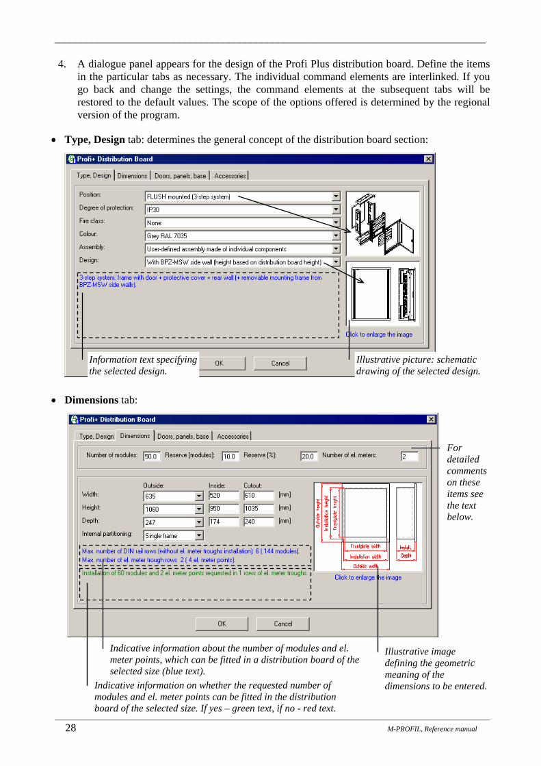
_______________________________________________________________________________
_______________________________________________________________________________________________________________________
28 M-PROFIL, Reference manual
4. A dialogue panel appears for the design of the Profi Plus distribution board. Define the items in the particular tabs as necessary. The individual command elements are interlinked. If you go back and change the settings, the command elements at the subsequent tabs will be restored to the default values. The scope of the options offered is determined by the regional version of the program.
• Type, Design tab: determines the general concept of the distribution board section:
• Dimensions tab:
Information text specifying the selected design.
Illustrative picture: schematic drawing of the selected design.
Indicative information about the number of modules and el. meter points, which can be fitted in a distribution board of the selected size (blue text).
Indicative information on whether the requested number of modules and el. meter points can be fitted in the distribution board of the selected size. If yes – green text, if no - red text.
Illustrative image defining the geometric meaning of the dimensions to be entered.
For detailed comments on these items see the text below.

_______________________________________________________________________________
_______________________________________________________________________________________________________________________
M-PROFIL, Reference Manual 29
• Number of modules: Specify the number of modules, which will be fitted with devices in the distribution board (the number of modules can be determined by qualified estimate, or by calculation based on the wiring diagram; one module corresponds to the width of 17.5 mm). It represents the actually occupied space. This item is enabled only if you follow the methodology A). In case you decided to follow the C) methodology – some devices have already been selected from the database, this item is disabled and the number of modules is determined automatically. The size of the distribution board can then be modified only by means of the Reserve tab. If you follow the methodology B), set the value to 0.
• Reserve (modules) – Enter the required reserve in the number of modules; the space corresponding to these modules should be left unoccupied. The reserve can be positive (enlargement of the distribution board), or negative (reduction). The subsequent item is calculated automatically based on the entered value.
• Reserve (%) – Here you can enter the required reserve as a percentage of the total number of modules. The reserve can be positive (enlargement of the distribution board), or negative (reduction). The previous item Reserve (modules) defining the space, which should remain unoccupied in the distribution board, is calculated automatically based on the entered value.
• Number of el. meter points – Enter the required minimum number of el. meter troughs in the distribution board.
It is obvious that the two fields concerning the reserve are two alternatives. Either you define the reserve as a number of modules, or as a percentage from the total number of modules. The total design size of the distribution board is then determined by the sum of the fields Number of modules + Reserve (modules).
• Internal partitioning: A distribution board can be composed of either one, or a combination of two different mounting frames – this is useful especially for wide distribution boards (easier handling with the mounting frame, partitioning of the interior space in the distribution board). Only those options are offered, which match the selected design.
• Door, panels, base tab:
Click on the picture to go to the corresponding list with the cursor. Double click to enlarge the image.
The options offered correspond to the selected concept (degree of protection, ...) defined under the Type, Design tab and to the selected dimensions of the distribution board.
Activation of the cable entry flange configurator

_______________________________________________________________________________
_______________________________________________________________________________________________________________________
30 M-PROFIL, Reference manual
If the top or bottom panel allows the mounting of cable entry flanges, it is necessary to specify, which flanges will be used:
1) Click on a picture to select a suitable flange.
2) Click on the button at the position where you want the flange to be fitted.
1) Select a panel allowing the mounting of cable entry flanges.
2) Click on the button to activate the cable entry flange configurator.

_______________________________________________________________________________
_______________________________________________________________________________________________________________________
M-PROFIL, Reference Manual 31
• Accessories tab:
5. Click OK to close the dialogue panel. The system will search for all components, which are necessary to assemble the selected type of the distribution board. A dimensional drawing will be shown (here a surface-mounted distribution board with a mounting frame in the rear and the possibility to mount cover plates):
Accessories typically used for every distribution board, which should not be omitted; any desired combination can be selected.
To view a list of the selected accessories, with a possibility to select any additional accessories as desired (see Chap. 17).
Functions for the view control (Zoom) of the drawing, see Chap. 22.
Modified project structure tree taking into account the selected distribution board system.
Double click on the branch to change the distribution board or to switch to a different distribution board system.

_______________________________________________________________________________
_______________________________________________________________________________________________________________________
32 M-PROFIL, Reference manual
Symbolic representation of N/PE terminal boards with threads mounted directly to the distribution board frame.
Indication of the door swing direction, here one-leaf door.
Mounting frame in the rear.
Cover plate line.
BPZ-MSW side wall to mount mounting rails and cover plates.
Indication of the door swing direction: here double-leaf door.
Flush-mounted distribution board - cutout (niche) in the wall
SURFACE-mounted distribution board

_______________________________________________________________________________
_______________________________________________________________________________________________________________________
M-PROFIL, Reference Manual 33
Floor-mounted distribution board, 1 frame Floor-mounted distribution board, 2 frames
Notes: • The dimensions of the distribution board frame can be changed at any moment by clicking
again on the Distribution Board branch in the project structure tree. In the same manner it is possible to switch over to a different distribution board system (such as compact distribution boxes). When changing the dimensions or when switching over to a different distribution board system, all linked components (mounting rails, el. meter troughs, cover plates, devices fitted) will be erased.
• A detailed design of the internal configuration (inserting mounting rails, mounting plates, SASY busbar system) takes place at the level of mounting rails and panels (see Chap. 10).
• For insertion of cover plates see Chap. 12. • The Temperature Rise function can be used to check whether the heat losses of the fitted
devices do not exceed the maximum value defined by the manufacturer, and to calculate the temperature rise in the distribution board according to IEC 890 (see Chap. 19).
• The Weight function can be used to calculate the weight of the distribution board and the devices fitted therein (see Chap. 21.6).
Indication of the door swing direction, here one-leaf door.
BPZ-MSW side wall to mount mounting rails and cover plates; the height is determined by the distribution board height.
Indication of the door swing direction: here double-leaf door.
Left frame Right frame
BPZ-MSW side wall to mount mounting rails and cover plates, reduced height. The bottom part includes space to mount power
devices to the mounting frame in the rear.
Base (plinth).

_______________________________________________________________________________
_______________________________________________________________________________________________________________________
34 M-PROFIL, Reference manual
8. Profi Plus Distribution Boards (Typical Assemblies) _______________________________________________
Profi Plus distribution boards provide a large variability of internal configuration, which inevitably implies a more complex design to a certain extent. It is necessary to define the distribution board frame, fit it with mounting rails and cover plates. This procedure needs to be repeated every time, also in case of standard versions. Typical assemblies consist in certain “semi-finished” standard distribution boards, which can be used as a starting point for the design. Typical assemblies save time and make the design of standard distribution boards easier. Surface-mounted Profi Plus distribution board Flush-mounted distribution board Profi Plus Typical assembly with DIN rails Typical assembly with DIN rails + el. meter troughs
The following basic procedures are possible in terms of the design logic applied to the distribution boards in the M-PROFIL system:
A) The number of modules and el. meter points is set to 0. In this case, the typical distribution board is selected from a comprehensive dimensional series based on the dimensions only. Devices are then selected from the device database (see Chap. 15) and tested for the possibility to fit into the respective frame. In the event of any difficulties, the standard assembly can be further modified (it is possible to change the position and number of mounting rails, cover plates, etc.).
B) First of all, devices are selected from the database (see Chap. 15). The number of modules occupied by these devices is calculated automatically. The typical assembly is selected based on the number of modules actually achieved, taking into account an appropriate reserve and number of el. meter points.
Designing a Profi Plus distribution board frame (typical assembly)
1. In the project structure tree, select the distribution board, for which you want to define the Profi Plus type (for inserting a new distribution board into the project and working with the project structure see Chap. 5).
2. Roll down the project structure tree by clicking on the “+” sign next to the distribution board name. Double click on the “Distribution Board” branch.
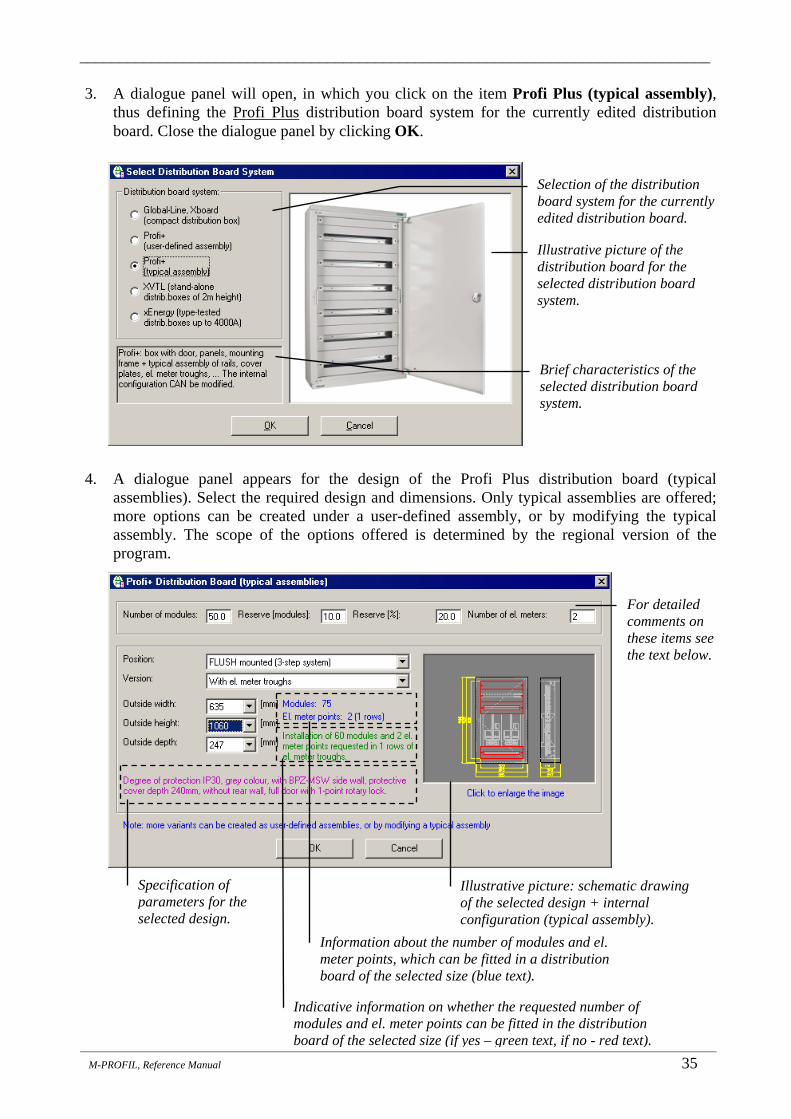
_______________________________________________________________________________
_______________________________________________________________________________________________________________________
M-PROFIL, Reference Manual 35
3. A dialogue panel will open, in which you click on the item Profi Plus (typical assembly), thus defining the Profi Plus distribution board system for the currently edited distribution board. Close the dialogue panel by clicking OK.
4. A dialogue panel appears for the design of the Profi Plus distribution board (typical
assemblies). Select the required design and dimensions. Only typical assemblies are offered; more options can be created under a user-defined assembly, or by modifying the typical assembly. The scope of the options offered is determined by the regional version of the program.
Selection of the distribution board system for the currently edited distribution board.
Illustrative picture of the distribution board for the selected distribution board system.
Brief characteristics of the selected distribution board system.
For detailed comments on these items see the text below.
Illustrative picture: schematic drawing of the selected design + internal configuration (typical assembly).
Specification of parameters for the selected design.
Information about the number of modules and el. meter points, which can be fitted in a distribution board of the selected size (blue text).
Indicative information on whether the requested number of modules and el. meter points can be fitted in the distribution board of the selected size (if yes – green text, if no - red text).

_______________________________________________________________________________
_______________________________________________________________________________________________________________________
36 M-PROFIL, Reference manual
• Number of modules: Specify the number of modules, which will be fitted with devices in the distribution board (the number of modules can be determined by qualified estimate, or by calculation based on the wiring diagram; one module corresponds to the width of 17.5 mm). It represents the actually occupied space. This item is enabled only if you follow the methodology A). In case you decided to follow the B) methodology – some devices have already been selected from the database, this item is disabled and the number of modules is determined automatically. The size of the distribution board can then be modified only by means of the Reserve tab.
• Reserve (modules) – Enter the required reserve in the number of modules; the space corresponding to these modules should be left unoccupied. The reserve can be positive (enlargement of the distribution board), or negative (reduction). The subsequent item is calculated automatically based on the entered value:
• Reserve (%) – Here you can enter the required reserve as a percentage of the total number of modules. The reserve can be positive (enlargement of the distribution board), or negative (reduction). The previous item Reserve (modules) defining the space, which should remain unoccupied in the distribution board, is calculated automatically based on the entered value.
• Number of el. meter points – Enter the required minimum number of el. meter troughs in the distribution board.
It is obvious that the two fields concerning the reserve are two alternatives. Either you define the reserve as a number of modules, or as a percentage from the total number of modules. The total design size of the distribution board is then determined by the sum of the fields Number of modules + Reserve (TE modules)
• Only typical assemblies are offered; more options can be created under a user-defined assembly, or by modifying the typical assembly.
• The scope of the options offered is determined by the regional version of the program. 5. Click OK to close the dialogue panel. The system will search for all components, which are
necessary to assemble the selected type of the distribution board. A dimensional drawing will be shown:

_______________________________________________________________________________
_______________________________________________________________________________________________________________________
M-PROFIL, Reference Manual 37
Notes: • A typical assembly can be modified in any desired way. You can:
• Change the type, position and number of mounting rails and mounting panels – see Chap. 10;
• Remove or add el. meter troughs – see Chap. 11; • Change the type, position and number of cover plates – see Chap. 12; • Add cable ducts – see Chap. 14; • Fit devices – see Chap. 15; • Insert accessories – see Chap. 17.
• The dimensions of the distribution board can be changed at any moment by clicking again on the Distribution Board branch in the project structure tree. In the same manner it is possible to switch over to a different distribution board system (such as compact distribution boxes). When changing the dimensions or when switching over to a different distribution board system, all linked components (mounting rails, el. meter troughs, cover plates, devices fitted) will be erased.
• If none of the typical assemblies matches the input requirements, it is necessary to design the distribution board as a user-defined assembly (see Chap. 7).
• The Temperature Rise function can be used to check whether the heat losses of the fitted devices do not exceed the maximum value defined by the manufacturer, and to calculate the temperature rise in the distribution board according to IEC 890 (see Chap. 19).
• The Weight function can be used to calculate the weight of the distribution board and the devices fitted therein (see Chap. 21.6).

_______________________________________________________________________________
_______________________________________________________________________________________________________________________
38 M-PROFIL, Reference Manual
9. Stand-alone Distribution Boxes _______________________________________________
The XVTL stand-alone distribution boxes complement the Profi Plus distribution boards with new types with the height of 2000mm and with various widths and depths for stand-alone or in-line distribution boards. These boxes are designed in particular for heavy-current circuits and can be fitted with power circuit devices with the possibility for universal mounting of various types of devices and busbars. They can be also used as distribution boards for instrumentation or compensation. The basic box equipment includes door, frame, top and rear panel. Depending on the relevant design, it is possible to order additional accessories (side walls, bases, …).
The xEnergy series distribution boxes are type-tested distribution boxes up to 4000A. Owing to their modular design, these distribution boxes offer a wide range of combinations that can be used for power circuit protection, compensation and automation. The combinations of mounting systems and panels have been optimized for the dimensions of Moeller devices.
9.1 XVTL stand-alone distribution boxes M-PROFIL allows interactive design of XVTL stand-alone distribution boxes in the following basic versions:
• Empty box – the internal configuration can be defined by interactively inserting (horizontal and vertical) supports (profiles) and mounting plates. Supports, mounting plates and busbar systems are inserted at the level of mounting rails (see Chap. 10).
• Box with a Profi Plus adapter – a front and/or rear Profi Plus adapter is mounted in the box for the purpose of installing devices up to 630A (see Chap. 7, 8). Mounting rails, cover plates and devices are fitted to this adapter in the same manner as with standard Profi Plus distribution boards. The possibility to mount supports, mounting plates and busbar systems is retained. Thus, the Profi Plus adapter combines the advantages of power distribution boards with those of installation distribution boards.
• Angle frame – for a series of distribution boards is connected to an angle; no additional components can be fitted.
Empty box Box with a front and rear Profi Plus adapter
Angle frame Box with an IZM series power circuit-breaker, main busbar at the top

_______________________________________________________________________________
_______________________________________________________________________________________________________________________
M-PROFIL, Reference manual 39
Designing a XVTL Stand-Alone Distribution Box
1. In the project structure tree, select the distribution board, for which you want to define the XVTL stand-alone distribution box (for inserting a new distribution board into the project and working with the project structure see Chap. 5).
2. Roll down the project structure tree by clicking on the “+” sign next to the distribution board name. Double click on the “Distribution Board” branch.
3. A dialogue panel will open, in which you click on the item XVTL (boxes with height up to 2,000 mm), thus defining the XVTL distribution box system for the currently edited distribution board. Close the dialogue panel by clicking OK.
4. A dialogue panel appears for the design of the XVTL stand-alone distribution box. Define the items in the particular tabs as necessary. The individual command elements are interlinked. If you go back and change the settings, the command elements at the subsequent tabs will be restored to the default values. The scope of the options offered is determined by the regional version of the program.
• Type, Design tab: determines the general concept of the distribution board section:
Selection of the distribution board system for the currently edited distribution board.
Illustrative picture of the distribution board for the selected distribution board system.
Brief characteristics of the selected distribution board system.
Illustrative picture: schematic drawing of the selected design

_______________________________________________________________________________
_______________________________________________________________________________________________________________________
40 M-PROFIL, Reference Manual
• Dimensions tab:
• Door, panels, base tab:
Click on the picture to go to the corresponding list with the cursor. Double click to enlarge the image.
The options offered correspond to the selected concept (degree of protection, ...) defined under the Type, Design tab and to the selected dimensions of the distribution board.

_______________________________________________________________________________
_______________________________________________________________________________________________________________________
M-PROFIL, Reference manual 41
If the top or bottom panel allows the mounting of cable entry flanges, it is necessary to specify, which flanges will be used:
1) Click on a picture to select a suitable flange.
2) Click on the button at the position where you want the flange to be fitted.
1) Select a panel allowing the mounting of cable entry flanges.
2) Click on the button to activate the cable entry flange configurator.

_______________________________________________________________________________
_______________________________________________________________________________________________________________________
42 M-PROFIL, Reference Manual
• Accessories tab:
5. Click OK to close the dialogue panel. The system will search for all components, which are
necessary to assemble the selected type of the distribution board. A dimensional drawing will be shown (here an empty-box version with main busbar supports at the top):
Frame/Door/Busbar View switch, see Chap. 5.9.
Accessories typically used for every distribution board, which should not be omitted; any desired combination can be selected.
To view a list of the selected accessories, with a possibility to select any additional accessories as desired (see Chap. 17).
Functions for the view control (Zoom) of the drawing, see Chap. 22.
Modified project structure tree taking into account the selected distribution board system.
Double click on the branch to change the distribution board or to switch to a different distribution board system.
A detailed design of the internal configuration –insertion of supports, mounting plates, busbars) takes place at the level of mounting rails (Chap. 10).
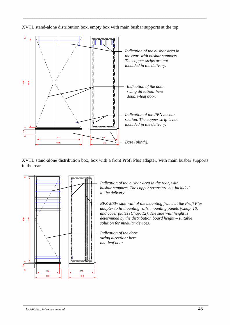
_______________________________________________________________________________
_______________________________________________________________________________________________________________________
M-PROFIL, Reference manual 43
XVTL stand-alone distribution box, empty box with main busbar supports at the top
XVTL stand-alone distribution box, box with a front Profi Plus adapter, with main busbar supports in the rear
BPZ-MSW side wall of the mounting frame at the Profi Plus adapter to fit mounting rails, mounting panels (Chap. 10) and cover plates (Chap. 12). The side wall height is determined by the distribution board height – suitable solution for modular devices.
Indication of the busbar area in the rear, with busbar supports. The copper straps are not included in the delivery.
Indication of the busbar area in the rear, with busbar supports. The copper strips are not included in the delivery.
Indication of the PEN busbar section. The copper strip is not included in the delivery.
Indication of the door swing direction: here double-leaf door.
Indication of the door swing direction: here one-leaf door
Base (plinth).

_______________________________________________________________________________
_______________________________________________________________________________________________________________________
44 M-PROFIL, Reference Manual
XVTL stand-alone distribution box, box with a front and rear Profi Plus adapter
XVTL stand-alone distribution box, box with pre-installation to mount NZM series power circuit-breakers
BPZ-MSW side wall of the mounting frame at the Profi Plus adapter to fit mounting rails, mounting panels (Chap. 10) and cover plates (Chap. 12). The side wall height is reduced only in the space where modular devices will be mounted.
Rear Profi Plus adapter to mount device modules (Chap. 10), to mount power circuit-breakers (analogically to the rear frame in surface-mounted or floor-mounted Profi Plus distribution boards).
Mounting plate for NZM4 circuit-breaker
Typical assembly – the internal configuration(position of supports and mounting plate) can be modified at the level of mounting rails (see Chap. 10).
Vertical support
Horizontal reinforcing support. In XVTL stand-alone distribution boxes, it is not included in delivery as standard; it needs to be ordered and mounted separately.
Rail to fix cables.

_______________________________________________________________________________
_______________________________________________________________________________________________________________________
M-PROFIL, Reference manual 45
XVTL stand-alone distribution box, box with pre-installation to mount IZM series power circuit-breakers
Notes: • A detailed design of the internal configuration (inserting supports, mounting plates, busbars or
fitting the Profi Plus adapter) takes place at the level of mounting rails (see Chap. 10). • For inserting cover plates see Chap. 12. • The dimensions or specification of the stand-alone distribution box can be changed at any
moment by clicking again on the Distribution Board branch in the project structure tree. In the same manner it is possible to switch over to a different distribution board system (such as Profi Plus distribution board).
• When changing the dimensions of the distribution board, all linked components (supports, mounting plates, mounting rails, el. meter troughs, cover plates) will be erased. Unless the distribution system is changed or the dimensions of the distribution system are modified, the linked components will be retained. This makes it possible to easily change the degree of protection or attach a base, for instance, at a later point in time.
• The designs of stand-alone distribution boxes with a mounting plate and a pre-installation to mount power circuit-breakers belong to typical assemblies – the internal configuration (position of supports) can be modified at the level of mounting rails (see Chap. 10).
• The Temperature Rise function can be used to check whether the heat losses of the fitted devices do not exceed the maximum value defined by the manufacturer, and to calculate the temperature rise in the distribution board according to IEC 890 (see Chap. 19).
• The Weight function can be used to calculate the weight of the distribution board and the devices fitted therein (see Chap. 21.6).
Typical assembly – the internal configuration (position of supports, mounting sets, etc.) can be modified at the level of mounting rails (see Chap. 10).
Light-weight horizontal support (to fix vertical busbars)
Fictitious mounting plate to fit the IZM circuit-breaker in M-PROFIL. Only an aid for working with the program; it shall not be ordered or mounted.
Heavy-weight horizontal support (for IZM circuit-breaker mounting sets).
IZM circuit-breaker mounting set (horizontal tray).
Rail to fix cables.
Light-weight horizontal support (to fix vertical busbars).

_______________________________________________________________________________
_______________________________________________________________________________________________________________________
46 M-PROFIL, Reference Manual
9.2 xEnergy distribution boxes xEnergy distribution boxes are type-tested distribution boxes up to 4000A. Owing to their modular design, these distribution boxes offer a wide range of combinations that can be used for power circuit protection, compensation and automation. The combinations of assembly systems and panels have been optimized for the dimensions of Moeller devices.
The xEnergy distribution system consists of type-tested functional modules, which fully comply with the requirements of the IEC 60439-1 standard as regards not only the individual details, but also the complete assembly. Besides the ordinary versions of distribution boxes with rather simple equipment (partitioning of form 1 to 2), it is also possible to design complex distribution boxes with interior partitioning of the areas (partitioning of form 3 to 4). You can benefit from the fact that the type-tested incoming-supply and connection sections with built-in busbars can be combined with IZM and NZM power circuit-breakers up to the current of 4000 A and, at the same time, you can use individually equipped outgoer sections for switching and protection of final circuits up to 630 A.
The M-PROFIL program allows the following three basic types of sections to be designed:
• Incomer section (includes one or two NZM power circuit-breakers, or one IZM circuit-breaker, type tested up to 4000A).
• Outgoer section (device modules can be fitted for mounting of protective devices for protection of final circuits; type-tested distribution boards up to 630A; protective devices can be fitted either horizontally or vertically).
• Universal section (mounting plates can be fitted that make it possible to install power-factor capacitors, frequency converters, softstarters, consumption-control devices, switching devices, automation components, etc.).
Designing an xEnergy distribution box
1. In the project structure tree, select the distribution box for which you want to define the box of the xEnergy distribution-box (for the inserting of a new distribution board into a project and for the operations with the project structure, please refer to Chap. 5).
2. Expand the project structure tree by clicking on the “+” sign next to the distribution box name. Double click the Distribution Board branch.
3. Click the item xEnergy (distribution system up to 4000A) at the dialogue panel that opens up subsequently. By doing so, you define the xEnergy system box for the distribution box being edited. Close the dialogue panel by clicking on the OK button.
Selection of the distribution system for the distribution box being edited.
Illustration drawing of the distribution boxes of the selected distribution system.
Brief characteristic of the selected distribution system

_______________________________________________________________________________
_______________________________________________________________________________________________________________________
M-PROFIL, Reference manual 47
4. A dialogue panel will be displayed for designing the xEnergy stand-alone distribution box. Set the items at the individual tabs as needed. The individual control elements are interlinked. After the return back, and after the setting has been changed, the control elements at the subsequent tabs switch over to the initial state.
• Type, Design tab: This tab determines the overall concept of the distribution box section:
• Dimensions tab:
• For the incomer section, the width is determined by the selected circuit-breaker. • Click on the Select Circuit-Breaker button; a list of the selected devices will be
displayed. • Select the required circuit-breaker (for a withdrawable version, select the base as well) –
see Chap. 15.1, 15.7. You must select 1 or 2 NZM circuit-breakers (at least NZM3, 250A) or one IZM circuit-breaker (at least 800A). In case of withdrawable version of NZM circuit-breakers, you will receive a query concerning the installation of a motor drive. The circuit-breaker type and number of poles must correspond to the settings of Fitting of devices under the previous tab Type, Design.
• Close a list of the selected devices by clicking on cross I upper right corner (or by pressing Esc key).
• In some cases, a width and a depth that are greater than the standard recommended values can optionally be selected. For the withdrawable version, the corresponding base must also be selected which, afterwards, does not need to be fitted.
Schematic representation of the positions of the busbars and outgoers.
Schematic representation of the interior arrangement
The value of current set here determines the dimension range; furthermore, this value can be specified more precisely (at the Busbars tab).

_______________________________________________________________________________
_______________________________________________________________________________________________________________________
48 M-PROFIL, Reference Manual
• For the incomer section, the width is determined by the selected circuit-breaker.
• For the outgoer section and universal section, dimensions can be selected from the options offered:
Width of the component mounting area + width of the cable connection area = overall width of the section (for an outgoer section) or width of the whole section.
An illustration drawing corresponding to the proposed section type. Click to enlarge the drawing.
Display the list of selected devices – the required circuit-breaker must be selected; for a withdrawable version, the socket must be included as well (for more details, please refer to Chap. 15.1, 15.6.). In some cases, a greater width can be selected subsequently.
Please, pay attention to these instructions.
Please, pay attention to these instructions.
An illustration drawing corresponding to the proposed section type.
Width is determined by the selected circuit-breaker.

_______________________________________________________________________________
_______________________________________________________________________________________________________________________
M-PROFIL, Reference manual 49
• Door, Panels, Base tab: This tab determines the overall covering of the distribution box:
Note: The side panel is packed in pairs for delivery; it is to be defined only for one of the outside sections of the switchgear.
Click on the drawing to move the cursor to the corresponding list.
The options offered correspond to the selected concept (degree of protection, etc.) defined at the “Type and Design” tab, and to the selected dimensions of the stand-alone distribution box.

_______________________________________________________________________________
_______________________________________________________________________________________________________________________
50 M-PROFIL, Reference Manual
• Partitions tab: By means of a suitable combination, the required partitioning form of the individual areas of the distribution board (IEC 60439-1) can be set; the ordinary partitioning of form 0 means that partitions are not used (everything has been eliminated).
The partitions offered depend on the selected concept and on the section type (here for incomer section).
Indication of the positions of partitions in the distribution board. The number corresponds to the number next to the check box. The drawing is only schematic, illustrative.
Pre-selection: Partitions necessary for partitioning of form 4b will be selected. Please, pay attention to the note written in blue.
Pre-selection: Partitions necessary for partitioning of form 2b will be selected.
Any combination of available partitions can be selected; the positions of the partitions selected are indicated by means of a violet line in the drawing on the right.
The partitions offered depend on the selected concept and on the section type (here for outgoer section).
Pre-selection: unselects all partitions (no partitioning)

_______________________________________________________________________________
_______________________________________________________________________________________________________________________
M-PROFIL, Reference manual 51
• Busbars tab:
• Accessories tab:
5. Close the dialogue panel by clicking on the OK button. The system will search out all the components that are necessary for assembling the selected distribution board type. The dimensional drawing will be drawn (in this case, the incomer section):
Accessories which are usually used for each section and should not be omitted; any combination can be selected.
Display the list of the selected accessories; option to select any other accessories (see Chap. 17)
Determining the position of the N and PE (PEN) busbars (they do not have to be included necessarily)
A more precise specification of the current of the main busbars (this has influence on the supports to be ordered; copper busbars are not included in the delivery).
A more precise specification of vertical busbars (only for the outgoer section). Supports and copper busbars with the shape of an H shape can be ordered. Vertical busbars are not drawn.
Recapitulation of the selected concept of the main busbars (as set at the Type, Construction tab)
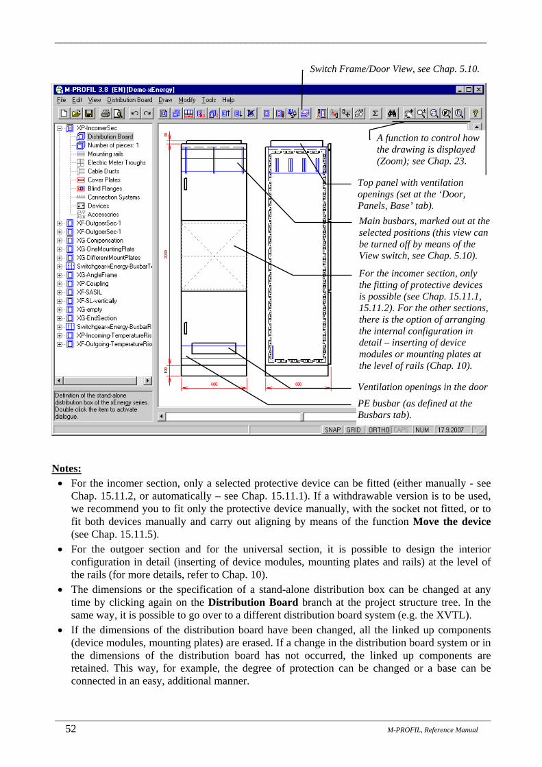
_______________________________________________________________________________
_______________________________________________________________________________________________________________________
52 M-PROFIL, Reference Manual
Notes: • For the incomer section, only a selected protective device can be fitted (either manually - see
Chap. 15.11.2, or automatically – see Chap. 15.11.1). If a withdrawable version is to be used, we recommend you to fit only the protective device manually, with the socket not fitted, or to fit both devices manually and carry out aligning by means of the function Move the device (see Chap. 15.11.5).
• For the outgoer section and for the universal section, it is possible to design the interior configuration in detail (inserting of device modules, mounting plates and rails) at the level of the rails (for more details, refer to Chap. 10).
• The dimensions or the specification of a stand-alone distribution box can be changed at any time by clicking again on the Distribution Board branch at the project structure tree. In the same way, it is possible to go over to a different distribution board system (e.g. the XVTL).
• If the dimensions of the distribution board have been changed, all the linked up components (device modules, mounting plates) are erased. If a change in the distribution board system or in the dimensions of the distribution board has not occurred, the linked up components are retained. This way, for example, the degree of protection can be changed or a base can be connected in an easy, additional manner.
A function to control how the drawing is displayed (Zoom); see Chap. 23.
For the incomer section, only the fitting of protective devices is possible (see Chap. 15.11.1, 15.11.2). For the other sections, there is the option of arranging the internal configuration in detail – inserting of device modules or mounting plates at the level of rails (Chap. 10).
Switch Frame/Door View, see Chap. 5.10.
Main busbars, marked out at the selected positions (this view can be turned off by means of the View switch, see Chap. 5.10).
Top panel with ventilation openings (set at the ‘Door, Panels, Base’ tab).
Ventilation openings in the door
PE busbar (as defined at the Busbars tab).
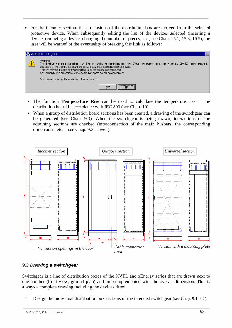
_______________________________________________________________________________
_______________________________________________________________________________________________________________________
M-PROFIL, Reference manual 53
• For the incomer section, the dimensions of the distribution box are derived from the selected protective device. When subsequently editing the list of the devices selected (inserting a device, removing a device, changing the number of pieces, etc.; see Chap. 15.1, 15.8, 15.9), the user will be warned of the eventuality of breaking this link as follows:
• The function Temperature Rise can be used to calculate the temperature rise in the distribution board in accordance with IEC 890 (see Chap. 19).
• When a group of distribution board sections has been created, a drawing of the switchgear can be generated (see Chap. 9.3). When the switchgear is being drawn, interactions of the adjoining sections are checked (interconnection of the main busbars, the corresponding dimensions, etc. – see Chap. 9.3 as well).
9.3 Drawing a switchgear Switchgear is a line of distribution boxes of the XVTL and xEnergy series that are drawn next to one another (front view, ground plan) and are complemented with the overall dimension. This is always a complete drawing including the devices fitted.
1. Design the individual distribution box sections of the intended switchgear (see Chap. 9.1, 9.2).
Outgoer section Incomer section Universal section
Cable connection area
Version with a mounting plate Ventilation openings in the door

_______________________________________________________________________________
_______________________________________________________________________________________________________________________
54 M-PROFIL, Reference Manual
• The switchgear may comprise distribution boxes of the XVTL or xEnergy series. • In a switchgear, only distribution boxes of the same distribution system may be placed
next to one another (only the XVTL or only the xEnergy system). • All the distribution boxes that make up a switchgear must be defined within the
framework of one project. • Adjacent sections are always checked for consistence (consistence of main busbars, etc.). • The order of the distribution boxes in the switchgear
corresponds to the order of the distribution boxes in the project structure (for changing the position of a distribution board in the project structure tree, refer to Chap. 5.8).
2. Insert the drawing of the switchgear in the project structure
(see Chap. 5.3), possibly, adapt the name of the switchgear (see Chap. 5.4).
3. Expand the project structure tree by clicking on the + sign next to the switchgear name. Double click on the Switchgear branch.
4. In the dialogue panel which opens up subsequently, specify the distribution board sections that make up the switchgear.
5. Close the dialogue panel by clicking on the OK button. The switchgear will be drawn.
List of the distribution boards in the project. Only the distribution boxes of the XVTL and xEnergy series that have not been included in the other switchgears can be accessed for inserting them in this switchgear. After inserting the first distribution box, only distribution boxes of the same distribution box series can be inserted (the first distribution box inserted was an XVTL distribution box, and so only XVTL series distribution boxes can be inserted afterwards).
List of the distribution boxes in the switchgear being edited. The order of the distribution boxes in the switchgear corresponds to the order of the distribution boxes in the project structure.
Insert the selected distribution box INTO the switchgear.
Remove the selected distribution box from the switchgear.
Double click on the selected distribution box = insert INTO the switchgear.

_______________________________________________________________________________
_______________________________________________________________________________________________________________________
M-PROFIL, Reference manual 55
Notes: • A complete drawing including the devices fitted is made. The visibility of the individual parts
can be modified using the Switch Frame/Door View function (see Chap. 5.10). • When the distribution board included in the switchgear has been edited (e.g. position of the
devices on the door has been changed), the switchgear drawing is automatically adjusted. • The switchgear drawing can be complemented with free graphics which are not transferred
back on the individual distribution boards included in the switchgear. • The definition can be changed at any time by clicking the Switchgear branch again.
A switchgear containing XVTL series distribution boards:
Distribution board name, transferred automatically.
Devices, free graphics transferred from the distribution board definition. Modifications are possible by editing the respective distribution board. Following the editing of a distribution board included in the switchgear, the switchgear drawing is adjusted automatically.
The sequence of distribution boards in the switchgear corresponds to their sequence in the project structure.
A plan view is drawn automatically.
The Frame/Door View switch makes it possible to switch off the display of some parts (mounting frame with devices, doors, busbars).

_______________________________________________________________________________
_______________________________________________________________________________________________________________________
56 M-PROFIL, Reference Manual
A switchgear containing xEnergy series distribution boards:
For distribution boxes, a check of consistent interconnections of the adjoining sections is performed. The values that have been detected are displayed at the dialogue panel, classified in the three basic levels: an error (displayed in red; an error must be fixed), a warning (displayed in blue, not necessarily a trouble), and an information.
The Frame/Door View switch makes it possible to switch off the display of some parts (mounting frame with devices, doors, busbars).
The general same rules apply as for a switchgear comprised of XVTL distribution boards (see the previous page).

_______________________________________________________________________________
_______________________________________________________________________________________________________________________
M-PROFIL, Reference Manual 57
10. Mounting Rails, Mounting Plates _______________________________________________
Rails are designed to mount devices to the distribution board frame. This category includes standard DIN rails, mounting plates (mounting panels), busbars, supports and device modules. Rails cannot be defined before the respective Profi Plus, XVTL, xEnergy distribution board is defined. Rails must be defined before any devices can be fitted. A previously inserted rail can be changed (modification of all parameters), and/or erased – cancelled. Mounting rails and mounting plates in Profi Plus distribution boards Mounting rails and mounting plates in XVTL distribution boards on a Profi Plus adapter
Rails can be mounted: • Directly to the mounting frame in the rear. • To the mounting frame in the rear on a fixed-depth tower BPZ-TF. • To the mounting frame in the rear on an adjustable-depth tower BPZ-TA, using a BEL
fastening element. • To the BPZ-MSW side wall using a BEL fastening element.
Mounting rail mounted to the mounting frame in the rear. RF0 (RF=Rear Frame) is the maximum mounting depth for the device. Suitable to mount power devices, contactors, terminals.
Mounting rail mounted to the mounting frame in the rear on an adjustable-depth tower BPZ-TA attached using a BEL fastening element. The mounting depth (T1…T6; T=Tower) for the devices can be adjusted by selecting a number of the slot, in which the BEL fastening element is fixed (higher number = greater depth). Suitable to mount both modular and power devices.
T0 (T=Tower) mounting rail mounted to the mounting frame in the rear on a fixed-depth tower BPZ-TF. Suitable to mount modular devices only.
Mounting depth for device. Rail height on the frame
(distance between the rail axis and the distribution board
frame bottom)
BPZ-TA tower
BEL fastening elementMounting rail
6 5 4 3 2 1 The mounting depth for device can be adjusted by selecting a number of the slot, in which the BEL fastening element is fixed (higher number = greater depth).

_______________________________________________________________________________
_______________________________________________________________________________________________________________________
58 M-PROFIL, Reference manual
Mounting information (indicated in the dimensional drawing at the right next to the side view):
Mounting rail mounted to the BPZ-MSW side wall attached by means of the BEL fastening element. The mounting depth for the device can be adjusted by selecting a number of the slot, in which the BEL fastening element is fixed (higher number = greater depth).
Depth SW5 (SW=Side Wall) is suitable to mount power devices, contactors, terminals.
Depth SW2 (SW=Side Wall) suitable to mount modular devices.
BPZ-MSW side wall
BEL fastening element
5 4 3 2 1
Mounting depth for device can be adjusted by selecting a number of the slot, in which the BEL fastening element is fixed (higher number = greater depth).
Mounting rail
Depth DS2 (DS=Depth Strap) on a TIW-1 depth strap is suitable to mount power devices, contactors, terminals.
Mounting depth for device.
Rail height on the frame (distance between the rail
axis and the distribution board frame bottom)
Type designation of the tower or depth strap, if present.
Rail height on the frame (distance between the rail axis and the distribution board frame bottom)
Depth on the tower (T...), in the side wall (SW...), or on the depth strap (DS...). The number represents the number of the slot, in which the BEL fastening element is fixed. RF = Rear Frame.
Type designation of the mounting rail, mounting plate, or device module.

_______________________________________________________________________________
_______________________________________________________________________________________________________________________
M-PROFIL, Reference Manual 59
Supports and mounting plates in the XVTL series boxes:
Mounting information (indicated in the dimensional drawing at the right next to the side view):
BPZ-MPL mounting plate fixed to the vertical support.
XVTL-VP vertical support (profile)
The little squares determine the position of the components on the box frame; the number of the square (counted from the door) determines the depth of the support, rail, mounting plate or busbar system in the box.
SASY busbar system fixed to a special panel BPZ-MPLSASY mounted to the side frame.
Height = distance between the component axis and the distribution board frame bottom.
Front plate support to fix vertical support and mounting plates throughout the box (included in the mounting set).
BPZ-DINR DIN rail fixed to the vertical support.
Reinforcing light-weight horizontal support XVTL-HP/L.
Rail to mount cables, here XVTL-AB L-profile on a XVTL-BRA bracket.
Rail to mount cables, here XAR C-profile on a vertical support.
Type designation of the support, mounting plate, mounting rail, or device module.
Height on the distribution board frame (distance between the rail axis and the distribution board frame bottom)
Depth of the distribution board side frame (SF=Side Frame), number of the little square (counted from the door).
Fictitious series on the mounting plate making the fitting of devices easier.

_______________________________________________________________________________
_______________________________________________________________________________________________________________________
60 M-PROFIL, Reference manual
Device modules in the xEnergy series distribution box (outgoer section):
Mounting plates in the xEnergy series distribution box (universal section):
Device modules with a mounting plate (for fitting a particular type of a circuit-breaker).
Partitions between modules (they will be drawn only if they were defined in the design of the distribution box – see Chap. 9.2).
Device module with a DIN rail
Device module, comprised only of a cover plate – in this case, with cutouts for measuring devices.
Mounting information: module type, height, depth
Height of the device modules, measured from the bottom of the stand-alone distribution box to the axis of the module
Mounting plate attached to the side wall (the side wall is not drawn).
DIN rail that can be cut as needed, attached to the mounting plate (it can also be attached individually, by means of automatically ordered angle pieces).
Mounting information: type of the rail or plate, height, depth
The height of the mounting plates or rails is measured from the bottom of the stand-alone distribution box to the axis of the plate or rail.
C-rail attached to the mounting plate, for cable-strain relief.
Rear edge of the side wall
Rear edge of the side wall (the side wall is not drawn in detail)

_______________________________________________________________________________
_______________________________________________________________________________________________________________________
M-PROFIL, Reference Manual 61
10.1 Inserting mounting rails, method A) – automatic fitting This option tries to cover the most frequent cases of distribution boards fitted with rails.
1. Roll down the project structure tree by clicking on the “+” sign next to the distribution board name. Double click on the Mounting Rails branch (the branch is present in the tree only if the Profi Plus, or XVTL, or xEnergy distribution board system was selected for the given distribution board). A window with the list of the already inserted mounting rails appears.
2. Click on the icon Insert Profi Plus mounting rails…. 3. The system will check whether a Profi Plus distribution board or an
XVTL distribution board with Profi Plus adapter is present. If this is the case, a dialogue panel appears (for more details see Chap. 10.2).
4. Select the distribution board frame (left or right), on which the rail is to be inserted (the frame selection is enabled only if there is more than one frame in the distribution board).
5. Select the rail type and subtype. 6. Select the connector type for the left and right side of the rail. 7. Define the rail depth. 8. Click AutoFit. The button is enabled only if a suitable rail type allowing the AutoFit function
was selected.
• The height of the 1st rail and the number of rails is determined based on the recommendation by Moeller in relation to the respective distribution board type. All rails automatically have the same depth (defined in step 3).
• The span between the rails is determined as to ensure that the distribution board can be closed with the most frequently used types of cover plates with a height of 150mm. Using this function will ensure that the cover plates can be fitted with a similar automatic mode (see Chap. 12.1). The rail width is determined automatically based on the distribution board frame width.
9. The AutoFit parameters can be modified in the dialogue panel. The values recommended for the respective distribution board are offered as default values. If you do not wish to make any change, click OK to close the panel; otherwise adjust the values as desired and close the panel by clicking OK – the system will first check the entered data for correctness and then fit the rails. The fitting takes place from bottom to top.
Notes: • The rail to be inserted is always checked for possible collision with the previously inserted rails
(el. meter troughs). The user is always prompted to indicate the next step (not insert the rail; insert the rail despite of the collision – to a greater depth, for instance). This ensures high variability.
The rail span must be a multiple of 25 mm.
The height of the first rail must correspond to its type and to the position of cutouts in the side wall.
The respective distribution board frame must be able to accommodate the number of rails entered here.

_______________________________________________________________________________
_______________________________________________________________________________________________________________________
62 M-PROFIL, Reference manual
• In case the inserted rails are not displayed in the dimensional drawing, please check whether the distribution board frame component view is enabled (see Chap. 5.9).
• For full description of the dialogue panel for rail insertion see Chap. 10.2.
10.2 Inserting mounting rails, method B) - inserting individual rails
1. Roll down the project structure tree by clicking on the “+” sign next to the distribution board name. Double click on the Mounting Rails branch (the branch is present in the tree only if the Profi Plus, XVTL, or xEnergy distribution board system was selected for the given distribution board). A window with the list of the already inserted mounting rails appears.
2. Click on the icon Insert Profi Plus mounting rails…. 3. The system will check whether a Profi Plus distribution board
or an XVTL distribution board with Profi Plus adapter is present. If this is the case, a dialogue panel appears.
4. Select the distribution board frame (left or right), on which the rail is to be inserted (the frame selection is enabled only if there is more than one frame in the distribution board).
5. Select the rail type and subtype. 6. Select the connector type for the left and right side of the rail. 7. Define the rail depth. 8. Enter a number to define the rail height. The height is offered automatically at 150 mm higher
than the last inserted rail (which corresponds to the height of the most frequently used cover plates) or at 75 mm higher than the highest el. meter trough. The distance entered is checked, and the closest possible value is offered in case of any incompatibility.
9. Close the dialogue panel by clicking OK.
• The system will check for collision with the previously inserted rails or cover plates. If everything is OK, the rails will be inserted in the list of selected rails and their position will be indicated in the drawing.
• The rail to be inserted is always checked for possible collision with the previously inserted rails (el. meter troughs). The user is always prompted to indicate the next step (not insert the rail; insert the rail despite of the collision – to a greater depth, for instance). This ensures high
Schematic drawing of the selected rail type and subtype + information about the possible mounting methods.Click to enlarge the picture.

_______________________________________________________________________________
_______________________________________________________________________________________________________________________
M-PROFIL, Reference Manual 63
variability. It is up to the user whether he wants to make only an illustrative economic design regardless of its feasibility (in such case, the collision warning can be ignored), or a final implementation project (in such case, the user must make the necessary modifications in order to avoid any warning messages).
• The system will automatically connect the required quantity of connecting materials and accessories.
• The rail width is determined automatically based on the distribution board frame width. Note: If an inserted rail is not displayed in the dimensional drawing, please check whether the distribution board frame component view is enabled (see Chap. 5.10).
Legend of abbreviations used in the list header:
• Description - description of the rail • Type – type designation of the rail • Frame – identification of the frame where the rail is mounted: L - left, R - right • Height – distance between the rail axis and the distribution board frame bottom • Depth – rail depth code:
• SW1, SW2, ... side wall and number indicating the slot in the side wall • T0, T1, ... tower and number indicating the slot in the tower • RF mounting directly to the distribution board rear frame • SF, SF1, SF2, ... mounting to the XVTL distribution board side frame
• Adap. - type designation of the adapter, if used • Ad.Ext. - adapter extension, if an adapter is used • Cp.L - type designation of the rail coupling (BEL fastening element) on the left if used • Cp.R - type designation of the rail coupling (BEL fastening element) on the right- if used • CabDucSupp - type designation of the cable duct support - if the shortened rail is used
10.3 Inserting supports and mounting plates into XVTL stand-alone distrib. boxes
1. Roll down the project structure tree by clicking on the “+” sign next to the distribution board name. Double click on the Mounting Rails branch (the branch is present in the tree only if the Profi Plus, XVTL or xEnergy distribution board system was selected for the given distribution board). A window with the list of the already inserted mounting rails appears.
2. Click on the icon Insert support/mounting plate….
Edit the selected rail. Insert DIN rail, mounting plate, busbar set, ...
Erase the selected rail.
The list of inserted rails is always sorted from top to bottom; if there are two frames in the distribution board, the left frame is first, then the right one.

_______________________________________________________________________________
_______________________________________________________________________________________________________________________
64 M-PROFIL, Reference manual
3. The system will check whether the currently edited distribution board is an XVTL stand-alone distribution box. If this is the case, a dialogue panel appears.
4. Select the type and subtype of the support or mounting plate to be inserted. 5. Define the depth in the box – enter a numeric value indicating the number of the slot in the
distribution box frame, counted from the door. Other options include side frame or rear frame. For mounting plates, it is necessary to define the depth of the relevant vertical support, to which the mounting plate is mounted.
6. Define the height in the box – enter a numeric value indicating the distance between the inside edge of the box and the center of the support / mounting plate (see the introduction to Chapter 10). The distance entered is checked, and the closest possible value is offered in case of any incompatibility (snap doesn’t correspond, collision with the edges, ...).
7. Close the dialogue panel by clicking OK. All geometrical relations will be checked (e.g. the
presence of a vertical support, collision with previously inserted rails at the respective depth, etc.). If everything is OK, the selected support / mounting plate will be inserted in the drawing.
Fitting IZM series circuit-breakers: The following components must be inserted one by one in order to be able to fit IZM circuit-breakers:
1. Heavy-weight horizontal support XVTL-HP/MIB 2. Circuit-breaker mounting set XVTL-IZM 3. Fictitious mounting plate to fit IZM circuit-breakers. This panel shall not be ordered or
mounted; it is only an aid for working with the program. Note: Instead of inserting the individual components one by one, it is better to insert an XVTL distribution box with a pre-installation to mount IZM circuit-breakers where the necessary components will be inserted automatically.
Schematic drawing of the selected rail type and subtype + information about the possible mounting methods. Click to enlarge the picture.
Please pay attention to this information.

_______________________________________________________________________________
_______________________________________________________________________________________________________________________
M-PROFIL, Reference Manual 65
10.4 Inserting a SASY busbar system into the XVTL stand-alone distribution boxes
1. Roll down the project structure tree by clicking on the “+” sign next to the distribution board name. Double click on the Mounting Rails branch (the branch is present in the tree only if the Profi Plus, XVTL or xEnergy distribution board system was selected for the given distribution board). A window with the list of the already inserted mounting rails appears.
2. Click on the icon Insert SASY busbar system…. 3. The system will check whether the currently edited
distribution board is Profi Plus, or XVTL. If this is the case, a dialogue panel appears:
Fictitious mounting plate to fit IZM circuit-breakers. The IZM circuit-breaker can be fitted manually like here (Chap. 15.11.2), or via AutoFit (Chap. 15.11.1)
Specification of accessories. The given type of the component will be specified automatically based on the busbar system parameters.
Number of busbar supports; the value offered must be adjusted based on the required short-circuit resistance.
Basic specification of the busbar system.
Definition of the busbar length depending on whether it goes through one or more distribution board fields.

_______________________________________________________________________________
_______________________________________________________________________________________________________________________
66 M-PROFIL, Reference manual
4. The basic type of the busbar system (brackets, busbars) is determined by the rated current and
the number of busbars. The busbar length depends on whether these busbars are joint busbars for several distribution board sections or only for a single distribution board:
5. Busbar position in the distribution box:
• The depth is entered as the depth of the BPZ-MPLSASY mounting plate or the BPZ-BR/SASY/H mounting adapter. The SASY busbar system can only be mounted with these equipment pieces, which must be inserted as mounting rails prior to calling this function (see Chap. 10.2, 10.3).
• The height is the distance between the inside edge of the box and the center of the busbar set (see the introduction to Chapter 10.). The distance entered is checked, and the closest possible value is offered in case of any incompatibility (snap doesn’t correspond, collision with the edges. Automatically, the program offers the height of an unoccupied BPZ-MPLSASY mounting plate or BPZ-BR/SASY/H mounting adapter.
Stand-alone distribution board. The busbar goes through the edited distribution board section, busbar length is determined automatically according to the section width.
Several sections next to each other, the busbar goes through all sections.
The busbar length will be determined in this section by the user, the busbars will be ordered (“busbar goes over TO adjacent sections”).
In these sections, the busbar “comes over FROM the adjacent section” and the busbars will not be ordered anymore.
Selection of additional accessories independent on the busbar system. For description of the accessories database control see Chap. 17.1. The list of such selected accessories can be edited in the Accessories branch (see Chap. 17).
Position of busbars in the distribution box; the depth is entered as the depth of the BPZ-MPLSASY mounting plate of the BPZ-BR/SASY/H mounting adapter. The height is the distance between the inside edge of the box and the center of the busbar set.
Please pay attention to these specifying comments.
Information about the presence of the BPZ-MPLSASY mounting plate or the BPZ-BR/SASY/H mounting adapter necessary for mounting.

_______________________________________________________________________________
_______________________________________________________________________________________________________________________
M-PROFIL, Reference Manual 67
6. Accessories comprise panels. By selecting the respective item you specify what should be ordered. A concrete component type will be specified automatically according to the busbar system parameters. Only those items, which are suitable from the design point of view, are enabled.
7. After clicking on the Other Accessories button, you can specify any additional components to the busbar system (for description of the accessories database explorer see Chap. 17.1). These accessories have no connection to the designed busbar system and will not be modified through editing. This list of accessories selected in this manner can be edited under the Accessories branch (see Chap. 17.3, 17.4).
8. Click OK to close the dialogue panel. The system will check whether a BPZ-MPLSASY mounting plate or a BPZ-BR/SASY/H mounting adapter is present at the respective depth and height. If this is the case, the busbar system will be inserted in the drawing.
SASY busbar system – front view.
Individual busbars.
SASY busbar system – side view.
Busbar support.
Wire connection adapter (inserted at the device level (Chap.15.1)).
Protective device at the mounting adapter (inserted at the device level (Chap.15.1) and moved (Chap. 15.11.5).
BPZ-MPLSASY mounting plate, to which the busbar system is attached.
BPZ-MPLSASY mounting plate
SASY busbar system

_______________________________________________________________________________
_______________________________________________________________________________________________________________________
68 M-PROFIL, Reference manual
Notes:
• Busbar systems can be fitted with adapters for cable connection as well as with adapters to connect NZM circuit breakers and PKZ motor starters. These adapters are inserted as devices for industrial application (see Chap. 15.1).
• If an inserted rail is not displayed in the dimensional drawing, please check whether the distribution board frame component view is enabled (see Chap. 5.9).
• When fitting devices to the adapter, it is at first necessary to fit the adapter on the busbars and the device itself on an auxiliary DIN rail or mounting plate (it can be also advantageous to use the “manual” fitting of an individual device - see Chap. 15.11.2). Then you have to move the device to the adapter by means of the Move device function from the Distribution Board drop-down menu (see Chap. 15.11.5).
Mounting adapter for NZM1 circuit-breaker.
Wire connection adapter.
NZM1 circuit-breaker fitted temporarily on the auxiliary mounting plate.
Device moved to the adapter using the Move Device function (Chap. 15.11.5) After editing:
device located on the adapter.
Mounting information; SASY busbar system is a set composed of partial components
(supports, busbars, panels, etc.).Number of busbars in the set.
Mounting plate, to which the busbar system is mounted (type
designation of mounting plate and fixing bracket).
Mounting information: H = height in the distribution board,
D = depth in the distribution board.
Nominal current of busbars.

_______________________________________________________________________________
_______________________________________________________________________________________________________________________
M-PROFIL, Reference Manual 69
10.5 Inserting device modules in the xEnergy stand-alone distribution boxes (outgoer section)
1. Expand the project structure tree by clicking on the + sign next to the
distribution board name. Double click on the Mounting Rails branch (this branch is in the tree only in the event that the Profi Plus, XVTL or xEnergy distribution system has been selected for the given distribution box). A window opens up with the list of the rails that have already been inserted.
2. Click on the xEnergy Mounting kits and Mounting Plates icon.
3. The system checks whether the distribution board being edited is a xEnergy stand-alone distribution box, an outgoer section. Should this prove to be the case, specify the device module in the dialogue panel that opens up subsequently:
4. Device modules are either of a type that is directly intended for mounting of particular
devices, or of a type that is intended for general installation of devices. A module is generally comprised of a mounting plate, or of a DIN rail and of a cover plate. It is not necessary to use the cover plate. Some modules comprise only a cover plate.
5. Close the dialogue panel by clicking on the OK buttons. The module will be inserted in the drawing.
6. If the function is called again, the highest of the modules that have been used is offered automatically. The height offered is automatically adjusted according to the height of the selected module. It is assumed that the modules will be fitted in the bottom-up direction.
View of the list of the selected devices; option of operative selection of a device complying with the module being inserted (see Chap. 15.1, 15.6).
The height is measured from the bottom of the stand-alone distribution box to the axis of the module. The height offered is automatically adjusted according to the height of the selected module. Bottom-up fitting is assumed.
Illustration drawing of the module selected. Click to enlarge the drawing.
Specification of the module being inserted.

_______________________________________________________________________________
_______________________________________________________________________________________________________________________
70 M-PROFIL, Reference manual
Note:
• In the event that the devices are to be fitted in a horizontal position, it is recommended that the selected devices should be fitted manually (see Chap. 15.11.2), instead of using the AutoFit mode.
• See also the drawings at the end of the introduction to Chapter 10.
10.6 Inserting of rails and mounting plates in the xEnergy stand-alone distribution boxes (universal sections)
1. Expand the project structure tree by clicking on the + sign next to the
distribution board name. Double click on the Mounting Rails branch (this branch is in the tree only in the event that the Profi Plus, XVTL or xEnergy distribution system has been selected for the given distribution box). A window opens up with the list of the rails that have already been inserted.
2. Click on the icon xEnergy Device Modules and Mounting Plates.
3. The system checks whether the distribution board being edited is a xEnergy distribution box, a universal section. Should this prove to be the case, specify the mounting plate / rail in the dialogue panel that opens up subsequently:
Illustration drawing of the selected plate/rail. Click to enlarge the drawing.
The height is measured from the bottom of the stand-alone distribution box to the axis of the plate/rail. The height offered is automatically adjusted according to the height of the selected plate. Bottom-up fitting is assumed.
Mounting plates and DIN rails intended for mounting of devices. C-rails for cable-strain relief. The rails are fitted on the mounting plates.
Type identification of the module (part: mounting plate).
Depth: The number of the opening in the side wall; the depth of the plate in the side wall is in the brackets.
Height: Distance of the module axis from the bottom of the stand-alone distribution box
Device module comprised of a mounting plate and of a cover plate (the device cutout is not drawn).
Not relevant in this case
Partition between modules (Partitions are only inserted if they were defined in the design of the stand-alone distribution box.)

_______________________________________________________________________________
_______________________________________________________________________________________________________________________
M-PROFIL, Reference Manual 71
4. Close the dialogue panel by clicking on the OK buttons. The plate / rail will be inserted in the drawing.
5. If the function is called again, the highest of the plates/rails that have been used is offered automatically. The offered height is automatically adjusted according to the height of the selected plate. It is assumed that the fitting will be carried out in the bottom-up direction. Rails can only be mounted on mounting plates (or a bracket must be manufactured), but the interaction between the rail and plate is not checked.
10.7 Editing a mounting rail (change in type, depth, height)
1. Roll down the project structure tree by clicking on the “+” sign next to the distribution board name. Double click on the “Mounting Rails” branch. A window with the list of the already inserted mounting rails appears.
2. Click on the line containing the rail, which you want to edit. 3. Click on the icon “Edit the selected rail”. 4. A dialogue panel will open identical to the one opening when you want to insert a rail. The
particular items are set according to the properties of the edited rail. It is possible to modify all properties while following identical rules as when inserting an individual rail (see Chap. 10.2). Similarly, if you have selected a bracket or a mounting plate in an XVTL stand-alone distribution box, or if you have selected a xEnergy device module, a dialogue panel opens up, as in the event that these items are being inserted (see Chap. 10.3, 10.4, 10.5, 10.6). If the SASY busbar system has been selected, a dialogue panel opens up, as in the event that this item is being inserted (see Chap. 10.4). The rail can only be changed if it has not been fitted with devices.
5. Close the dialogue panel by clicking OK. The data about the rail will be corrected in the list and the dimensional drawing will be repainted.
6. If you close the dialogue panel by clicking Cancel, the data will remain unchanged. 7. Close the window with the list of mounting rails by clicking on the X in the upper right corner
of the window or by pressing Esc. Tip: Double click on the respective line in the list of the selected mounting rails to go directly to the dialogue panel allowing you to modify the rail properties.
Type of the rail (or mounting plate).
Height: The distance of the axis of the rail (plate) from the bottom of the stand-alone distribution box.
Dsw = Depth in the Side Wall (the order of the opening).
Mounting plate in the side wall (the side wall is not drawn; only its rear edge is marked out). A C-rail on the mounting plate, for cable-strain relief (The check for the presence of the mounting plate under the C-rail is not carried out; the rail can also be attached directly to the side wall, namely by means of angle pieces.)
Virtual lines on the mounting plate make it easy to fit the devices.
Note: See also the drawings at the end of the introduction to Chapter 10.

_______________________________________________________________________________
_______________________________________________________________________________________________________________________
72 M-PROFIL, Reference manual
10.8 Erasing a mounting rail
1. Roll down the project structure tree by clicking on the “+” sign next to the distribution board name. Double click on the “Mounting Rails” branch. A window with the list of the already inserted mounting rails appears.
2. Click on the line containing the rail, which you want to erase. 3. Click on the icon “Erase the selected rail”. The rail will be erased from the list (and
from the dimensional drawing as well) and the pointer will be set to the previous rail. Click on the icon “Erase the selected rail” repeatedly to erase all rails from the list. The rail can only be erased if it is not fitted with devices.
4. Close the window with the list of mounting rails by clicking on the X in the upper right corner of the window or by pressing Esc.
Tip: If you click with your right mouse button in the list of the selected mounting rails, a context menu will appear allowing you to make a quick function selection (erase rail, edit rail, insert rail) and to apply it to the selected line.

_______________________________________________________________________________
_______________________________________________________________________________________________________________________
M-PROFIL, Reference Manual 73
11. Electric Meter Troughs _______________________________________________
An electric meter trough consists in an assembly to mount a respective number of electric meters. It can be fitted with an el. meter panel or a mounting set to mount modular devices.
11.1 Inserting an Electric Meter Trough
1. Roll down the project structure tree by clicking on the “+” sign next to the distribution board name. Double click on the “El. Meter Troughs” branch (the branch is present in the tree only if the Profi Plus or XVTL distribution board system was selected for the given distribution board). The system will check whether a Profi Plus distribution board or an XVTL distribution board with Profi Plus adapter is present. If this is the case, a window with the list of the already inserted el. meter troughs appears.
2. Click on the icon Insert el. meter trough. 3. A dialogue panel will open, in which you select the distribution board frame (left or right), on
which the trough is to be inserted (the frame selection is enabled only if there is more than one frame in the distribution board).
4. Select the type of the el. meter trough. 5. Define the fitting for every el. meter point – by selecting from the list of options offered
below the picture. The number of el. meter points is determined by the distribution board frame width). The el. meter point may remain empty, or it can be fitted with an el. meter panel. The outmost el. meter points can be fitted with DIN rails to mount modular devices.
Empty electric meter trough – two electric meter points
El. meter trough with one electric meter point and a mounting set to mount modular devices
Electric meter panel

_______________________________________________________________________________
_______________________________________________________________________________________________________________________
74 M-PROFIL, Reference manual
This can be useful, for instance, when you need to mount protection devices in case of an uneven number of el. meter points, where one point would otherwise remain unused).
6. Enter the height of the el. meter trough top edge from the distribution board frame bottom. • The minimum necessary height for the given trough type, or the height with respect to the
highest cover plate is offered as a default value. • When fitting a distribution board, it is recommended to first insert cover plates below the
el. meter trough (see Chap. 12), then the el. meter trough itself and only then the cover plates above the el. meter trough. This means that a bottom-up approach should be applied when fitting a distribution board.
• Once the value is entered, the system will check the height for correctness; the closest suitable value will be offered in case of any incompatibility.
7. Close the dialogue panel by clicking OK. The system will check for possible collision with
the existing (previously inserted) rails, el. meter troughs or cover plates. If everything is OK, the trough will be inserted in the list of the selected el. meter troughs and will be indicated in the dimensional drawing.
8. Close the window with the list of el. meter troughs by clicking on the X in the top right corner or by pressing Esc.
Note:
• If an inserted trough is not displayed in the dimensional drawing, please check whether the distribution board frame component view is enabled (see Chap. 5.10).
Schematic drawing of an el. meter trough. The number of el. meter points is determined by the distribution board frame width.

_______________________________________________________________________________
_______________________________________________________________________________________________________________________
M-PROFIL, Reference Manual 75
Depiction of an electric meter trough in the dimensional drawing (Profi Plus distribution board):
Edit the selected trough. Insert electric meter trough.
Erase the selected trough.
The list of inserted troughs is always sorted from top to bottom; if there are two frames in the distribution board, the left frame is first, then the right one.
Distance between trough top and distribution board frame bottom.
Identification of the frame, on which the trough is mounted; L - left, R - right.
El. meter trough with four electric meters on the distribution board frame.
El. meter trough type. Empty el. meter point.
El. meter point fitted with an el. meter panel.
El. meter point fitted with a DIN rail set to mount modular devices.
Mounting information: el. meter trough type and
distance between the el. meter trough top and distribution
board frame bottom.
El. meter trough in the side view.
Type of the el. meter panel or DIN rail set.

_______________________________________________________________________________
_______________________________________________________________________________________________________________________
76 M-PROFIL, Reference manual
11.2 Editing an electric meter trough
1. Roll down the project structure tree by clicking on the “+” sign next to the distribution board name. Double click on the “Electric Meter Troughs” branch. The system will check whether a Profi Plus distribution board or an XVTL distribution board with Profi Plus adapter is present. If this is the case, a window with the list of the already inserted el. meter troughs appears.
2. Click on the line containing the trough, which you want to edit. 3. Click on the icon “Edit the selected electric meter trough”. 4. A dialogue panel will open identical to the one opening when you want to insert an electric
meter trough. The particular items are set according to the properties of the edited trough. It is possible to modify all properties while following identical rules as when inserting an individual trough (see Chap. 11.1).
5. Close the dialogue panel by clicking OK. The meter trough data will be corrected in the list and the dimensional drawing will be re-sketched.
6. If you close the dialogue panel by clicking Cancel, the data will remain unchanged. 7. Close the window with the list of electric meter troughs by clicking on the X in the right
corner or by pressing Esc. Tip: Double click on the respective line in the list of the selected electric meter troughs to go directly to the dialogue panel allowing you to modify the trough properties.
11.3 Erasing an electric meter trough
1. Roll down the project structure tree by clicking on the “+” sign next to the distribution board name. Double click on the “Electric Meter Troughs” branch. The system will check whether a Profi Plus distribution board or an XVTL distribution board with Profi Plus adapter is present. If this is the case, a window with the list of the already inserted el. meter troughs appears.
2. Click on the line containing the trough, which you want to erase. 3. Click on the icon “Erase the selected electric meter trough”. The trough will be
erased from the list (and from the dimensional drawing as well) and the pointer will be set to the previous rail. Click on the icon “Erase the selected electric meter trough” repeatedly to erase all troughs from the list.
4. Close the window with the list of electric meter troughs by clicking on the X in the right corner or by pressing Esc.
Tip: If you click with your right mouse button in the list of the selected electric meter troughs, a context menu will appear allowing you to make a quick function selection (erase trough, edit trough, insert trough) and to apply it to the selected line.

_______________________________________________________________________________
_______________________________________________________________________________________________________________________
M-PROFIL, Reference Manual 77
12. Cover Plates _______________________________________________
Cover plates are designed to cover the front panel of the frame in a distribution board fitted with devices. The width of the cover plates is derived automatically from the distribution board width. The height of the cover plates is different for every type and width (series of different heights are manufactured for every type and width). The plates can be placed at any desired height. The reference point to measure the height is the top left corner of the plate.
12.1 Inserting cover plates, method A) - automatic fitting This option tries to cover the most frequent cases of distribution boards fitted with cover plates. The specified number of the selected cover plate type is inserted similarly to the mounting rail AutoFit. There is no connection between the cover plates and rails in the M-PROFIL version. The alignment of the cover plate cutouts with the rails is to be monitored by the user itself based on the appearance of the dimensional drawing.
1. Roll down the project structure tree by clicking on the “+” sign next to the distribution board name. Double click on the “Cover Plates” branch (the branch is provided in the tree only if the Profi Plus, or XVTL distribution board system was selected for the given distribution board).
2. The system will check whether a Profi Plus distribution board or an XVTL distribution board with Profi Plus adapter is present. If this is the case, a window with the list of the already inserted cover plates appears.
Cover plate with 45mm cutout for modular devices
Cover plate without cutout
Cover plate with holes for RMQ command and signalling devices
Cover plate without cutout, with a plastic panel (for power circuit-breakers). The necessary cutout will be made during the mounting based on the actual requirements.

_______________________________________________________________________________
_______________________________________________________________________________________________________________________
M-PROFIL, Reference Manual 77
3. Click on the icon Insert cover plate. 4. A dialogue panel appears (see Chap. 12.2), in which you select the distribution board
frame (left or right), on which the plates are to be inserted (the frame selection is enabled only if there is more than one frame in the distribution board).
5. Select the cover plate type. 6. Select the cover plate height from the list of options offered (different heights are available
for different types of cover plates and different distribution board widths). 7. Click on the AutoFit button.
• The height of the first cover plate and the number of plates is determined automatically according to the height of the space between the last cover plate (el. meter trough) and the top of the distribution board.
• The cover plate span is determined according to the selected plate height. • The width of the cover plates is determined automatically based on the distribution board
frame width.
8. The AutoFit parameters can be modified in the dialogue panel. The values recommended for the respective distribution board are offered as default values. If you do not wish to make any change, click OK to close the panel; otherwise adjust the values as desired and close the panel by clicking OK – the system will first check the entered data for correctness and then fit the cover plates. The fitting takes place from bottom to top.
8. Close the window with the list of cover plates by clicking on the X in the upper right corner of the window or by pressing Esc.
Notes:
• Every cover plate to be inserted is always checked for possible collision with the previously inserted plates (el. meter troughs). In case of a collision, the plate cannot be inserted.
• If an inserted plate is not displayed in the dimensional drawing, please check whether the distribution board frame component view is enabled (see Chap. 5.9).
• For full description of the dialogue panel appearing to insert cover plates see Chap. 12.2.
12.2 Inserting cover plates, method B) - inserting individual plates
1. Roll down the project structure tree by clicking on the “+” sign next to the distribution board name. Double click on the Cover Plates branch (the branch is present in the tree only if the Profi+, XVTL distribution board system was selected for the given distribution board).
2. The system will check whether a Profi+ distribution board or an XVTL distribution board with Profi+ adapter is present. If this is
The plate span corresponds to the plate height.
Distance between the left top corner of the first plate and the frame bottom.
The respective distribution board frame must accommodate the number of cover plates entered.

_______________________________________________________________________________
_______________________________________________________________________________________________________________________
78 M-PROFIL, Reference manual
the case, a window with the list of the already inserted cover plates appears. 3. Click on the icon Insert cover plate. 4. A dialogue panel appears, in which you select the distribution board frame (left or right), on
which the plates are to be inserted (the frame selection is enabled only if there is more than one frame in the distribution board).
5. Select the plate type, which you want to insert. 6. Define the item Height, represented by a list of all cover plates manufactured for the given
type, for the required plate height. When selecting a suitable cover plate, you can use – as an indicative tool – the aid at the bottom part of the dialogue panel, which shows the part of the distribution board frame that still needs to be covered. If a cover plate without cutout is selected, the program will automatically try to find a suitable plate height.
7. Define the position of the plate on the distribution board frame, i.e. the distance between the top left corner of the cover plate and the frame bottom. The position of the highest plate (or the highest el. meter trough) + height of the selected plate is offered automatically. Now it is essential to take into account any previously inserted rails and to place cover plates with cutout so that they are aligned with the existing rails. If you require el. meter troughs to be fitted, it is recommended to first insert all cover plates below the trough, then the trough itself (see Chap. 11) and only then the cover plates above the trough. This means that a bottom-up approach should be applied when fitting a distribution board.
8. Close the dialogue panel by clicking OK. The system will check whether the cover plate to be inserted does not collide with previously inserted cover plates or el. meter troughs (which cannot be covered by cover plates). In case of a collision, the plate cannot be inserted. If everything is OK, the selected plate will be inserted in the list of selected cover plates and displayed in the dimensional drawing.
9. Close the window with the list of cover plates by clicking on the X in the upper right corner of the window or by pressing Esc.
Note:
• If an inserted plate is not displayed in the dimensional drawing, please check whether the distribution board frame component view is enabled (see Chap. 5.9).
Schematic drawing of the selected cover plate type. Click to enlarge the picture.
Automatically cover the frame with cover plates, see Chap. 12.1.
Designing tool – the frame height, the height of previously inserted plates and el. meter troughs and the remaining height to be covered with plates, must be > or = 0.

_______________________________________________________________________________
_______________________________________________________________________________________________________________________
M-PROFIL, Reference Manual 79
Depiction of cover plates in the dimensional drawing (Profi+ distribution board):
Edit selected cover plate. Insert cover plate, AutoFit cover plates.
Erase selected cover plate.
List of inserted cover plates is always sorted from top to bottom; if there are two frames in the distribution board, the left frame is first, then the right one.
Distance between the cover plate top and the frame bottom.
Identification of the frame, on which the cover plate is mounted; L - left, R - right.
Cover plate without cutout.
Cover plate with a cutout for devices. M-PROFIL does not offer the option to hide invisible edges, the cover plates are “transparent”.
Mounting information – cover plate type designation.

_______________________________________________________________________________
_______________________________________________________________________________________________________________________
80 M-PROFIL, Reference manual
12.3 Editing a cover plate (change in type, height or position on the frame) 1. Roll down the project structure tree by clicking on the “+” sign next to the distribution board
name. Double click on the “Cover Plates” branch (the branch is present in the tree only if the Profi+ or XVTL distribution board system was selected for the given distribution board).
2. The system will check whether a Profi+ distribution board or an XVTL distribution board with Profi+ adapter is present. If this is the case, a window with the list of the already inserted cover plates appears.
3. Click on the line containing the plate, which you want to edit. 4. Click on the icon “Edit the selected cover plate”. 5. A dialogue panel will open identical to the one opening when you want to insert a cover plate.
The particular items are set according to the properties of the edited plate. It is possible to modify all properties while following identical rules as when inserting an individual cover plate (see Chap. 12.2).
6. Close the dialogue panel by clicking OK. The cover plate data in the list will be adjusted and the dimensional drawing will be re-sketched.
7. If you close the dialogue panel by clicking Cancel, the data will remain unchanged. 8. Close the window with the list of cover plates by clicking on the X in the upper right corner
of the window or by pressing Esc. Tip: Double click on the respective line in the list of the selected cover plates to go directly to the dialogue panel allowing you to modify the plate properties.
12.4 Erasing a cover plate
1. Roll down the project structure tree by clicking on the “+” sign next to the distribution board name. Double click on the “Cover Plates” branch (the branch is present in the tree only if the Profi+ or XVTL distribution board system was selected for the given distribution board).
2. The system will check whether a Profi+ distribution board or an XVTL distribution board with Profi+ adapter is present. If this is the case, a window with the list of the already inserted cover plates appears.
3. Click on the line containing the plate, which you want to erase. 4. Click on the icon “Erase the selected cover plate”. The plate will be deleted from the
list (and erased from the dimensional drawing as well) and the pointer will be set to the previous plate. Click on the icon “Erase the selected cover plate” repeatedly to erase all plates from the list.
5. Close the window with the list of cover plates by clicking on the X in the upper right corner of the window or by pressing Esc.
Tip: If you click with your right mouse button in the list of the selected cover plates, a context menu will appear allowing you to make a quick function selection (erase cover plate, edit cover plate, insert cover plate) and to apply it to the selected line.

_______________________________________________________________________________
_______________________________________________________________________________________________________________________
M-PROFIL, Reference Manual 81
13. Blind Flanges _______________________________________________
A cutout in the cover plate, which is not fitted with any device, can be closed by means of blind flanges. The following basic types of blind flanges are available:
• Blind flange with fixed width (typically 0.5 of the module, i.e. 8.75 mm), which cannot be divided further. The required segment will be filled by repeated insertion of 1 piece, thus, it does not have to be covered completely. Some types can be sealable, i.e. they cannot be removed from the cutout without removing the cover plate.
• Breakable blind flange: a band made of hard plastic ad having a certain maximum length with reductions in precisely defined spacing (1 or 0.5 module, i.e. 17.5 or 8.75 mm, respectively) - thus it is possible to reduce the blind flange length by breaking off these segments. Therefore, the required segment does not have to be covered completely. Some types can be sealable, i.e. they cannot be removed from the cutout without removing the cover plate.
• Freely cuttable blind flange: a band of certain length, from which the required segment can be cut precisely.
The user creates a list of the selected blind flanges. Blind flanges from the list can be fitted into the cutouts in cover plates (thereby being broken and cut). For the purposes of the breakdown list generation, the particular segments are summarized in order to ensure that the required number of pieces of the given type will be ordered. It is advisable to insert the blind flanges only after all the devices are fitted to the distribution board rails (see Chap. 15.11) and after the distribution board frame is covered completely with cover plates (see Chap. 12.1, 12.2).
13.1 Inserting blind flanges, method A) - automatic fitting This selection allows you to cover free cutouts in cover plates with minimum operator requirements. Preconditions for successful AutoFit of the blind flanges are that all devices are completely fitted to the distribution board rails (see Chap. 15.11), the frame is completely covered with cover plates (see Chap. 12.1, 12.2) and that the requirement for all free cutouts being blinded with a single blind-flange type is met.
1. Roll down the project structure tree by clicking on the “+” sign next to the distribution board name. Double click on the “Blind Flanges” branch (the branch is present in the tree only if some distribution board system has already been selected). The system checks whether it is possible to insert cover plates with cutouts for devices. Should this prove to be the case, a window opens up with a list of blind flanges that have already been inserted.
2. Click on the icon “Insert blind flange”. 3. Click on the respective image to select the blind-flange type (for full description of the
dialogue panel see Chap. 13.2). 4. Click on the AutoFit button. All free cutouts in the cover plates will be blinded with the
selected type of the blind flange (the blind flanges will be inserted in the list and drawn in the cutouts).
5. Close the window with the list of cover plates by clicking on the X in the upper right corner of the window or by pressing Esc.

_______________________________________________________________________________
_______________________________________________________________________________________________________________________
82 M-PROFIL, Reference manual
Note: • Unfitted blind flanges will be deleted from the list of the selected blind flanges. • Blind flanges, which have been fitted into the cutouts previously, will be retained in place
(the AutoFit mode fills only free cutouts that are not fitted with devices or previously inserted blind flanges).
• If the inserted blind flanges are not displayed in the dimensional drawing, please check whether the distribution board frame component view is enabled (see Chap. 5.9).
13.2 Inserting blind flanges, method B) - inserting individual pieces in the list
1. Roll down the project structure tree by clicking on the “+” sign next to the distribution board name. Double click on the “Blind Flanges” branch (the branch is present in the tree only if some distribution board system has already been selected). The system checks whether it is possible to insert cover plates with cutouts for devices. Should this prove to be the case, a window opens up with a list of blind flanges that have already been inserted.
2. Click on the icon “Insert blind flange”. 3. The following dialogue panel appears:
4. In the subsequently opened dialogue panel, click on the respective image to select the desired
blind-flange type you want to insert. 5. Enter the required number of pieces of the inserted blind flange. The information about the
length of the given number of pieces of blind flanges (calculated after pressing Enter) and the information about the length remaining to be blinded serves as an aid.
Click on the picture to select the blind flange. Double click to enlarge the picture.
Number of pieces of the selected blind flange, which will be inserted in the list.
Number of modules, which represents the specified quantity of the selected blind flange.
The blinded length in mm, which represents the specified quantity of the selected blind flange. Design tool informing about the length still remaining to be covered with blind flanges. The remaining length should be <= 0.
Insert the specified quantity of the selected type of blind flanges in the list of the selected blind flanges (not in the cutouts).
Automatic coverage of free cutouts with blind flanges, see Chap. 13.1.

_______________________________________________________________________________
_______________________________________________________________________________________________________________________
M-PROFIL, Reference Manual 83
6. Close the dialogue panel by clicking OK. The required number of pieces of the given blind-flange type will be inserted in the list of the selected blind flanges. The maximum blind-flange length is always inserted. The blind flange can be subsequently fitted into the cutout in the cover plate, see Chap. 13.3.
7. Close the window with the list of blind flanges by clicking on the X in the right corner or by pressing Esc.
Notes: • Various types of blind flanges can be inserted by repeated activation of this function. • If you want to check whether all cutouts in the frame cover plates are blinded, activate this
function again - if the information indicating the Length remaining to be blinded is less than or equal to 0, then all cutouts are blinded. In such case, you can close the dialogue panel by clicking Cancel.
Fit blind flange from the list in the cover plate cutout. Insert blind flange, AutoFit blind flanges.
Erase the selected blind flange from the list.
List of selected blind flanges is always sorted from top to bottom and from left to right; if there are two frames in the distribution board, the left frame is first, then the right one. Unfitted blind flanges are at the end of the list.
Position of the blind flange on the frame (coordinates of the left center); identification of the frame, on which the blind flange is mounted: [L] - left, [R] - right.
Current number of segments of the breakable blind flange.
Erase blind flange from the cover plate cutout (however, not from the list the selected blind flanges).
Blind flange that is not fitted in the cover plate cutout is indicated in red.
Blind flange that is fitted in the cover plate cutout is written in black.
Current length of the freely cuttable blind flange.

_______________________________________________________________________________
_______________________________________________________________________________________________________________________
84 M-PROFIL, Reference manual
Depiction of blind flanges in the dimensional drawing:
13.3 Fitting a blind flange from the list into the cover plate cutout Blind flanges inserted in accordance with the procedure described in Chap. 13.2 are inserted in the list of selected blind flanges, but not into the cutout in the cover plate. Through the procedure specified below, you can insert a blind flange into the cutout in the cover plate, thereby displaying it in the dimensional drawing of the distribution board.
1. Roll down the project structure tree by clicking on the “+” sign next to the distribution board name. Double click on the “Blind Flanges” branch (the branch is present in the tree only if a distribution board system has already been selected). The system will check whether it is possible to insert cover plates with cutouts for devices. If this is the case, a window with the list of the already inserted blind flanges appears.
2. Click on the line containing the blind flange, which you want to fit into the cover plate cutout. The blind flange may not be fitted already (must be written in red).
3. Click on the icon “Fit the selected blind flange to the cutout”. 4. The panel with the list of the selected blind flanges will be closed. The pointer will change to
a cross-hair shape. Double click in the cover plate cutout, into which you want to insert the selected blind flange. It is possible to click on any point within the unblinded cutout.
5. The system checks whether a point within an unblinded cutout was clicked. If this is not the case, an error message will be generated and the list of the selected blind flanges will appear again. If everything is OK, the blind flange will be inserted into the specified cutout in such a manner that it will be assigned to the closest device/blind flange to the left from the clicked point. In case the blind flange laps over the specified cutout, its width will be adjusted by
Removable blind flange in Global-Line compact distribution box (inserted automatically in some types of compact distribution boxes and can be only erased).
Devices fitted in the cover plate cutouts.
Breakable blind flange fitted in the cover plate cutout.
Freely cuttable blind flange fitted in the cover plate cutout.
Free cutout in the cover plate, prepared to be covered with blind flanges.
Note: It is not possible to hide invisible edges in M-PROFIL; devices, cover plates and blind flanges are “transparent”.

_______________________________________________________________________________
_______________________________________________________________________________________________________________________
M-PROFIL, Reference Manual 85
breaking off the required number of segments or by cutting away the segment with the required width.
6. The list of the selected blind flanges appears again. The list of the selected blind flanges is always arranged from top to bottom and from left to right; if there are two frames in the distribution board, the left frame is shown as first; the right frame is shown as second. Unfitted blind flanges are shown in the beginning of the list. Therefore, the position of a just fitted blind flange can change in the list. Once fitted, the next unfitted blind flange is selected automatically.
7. Fit all unfitted blind flanges by repeating the steps 2…6. A new blind flange to be inserted can be added by applying the procedure described in Chap. 13.2, redundant blind flanges can be erased by applying the procedure described in Chap. 13.5.
8. Close the window with the list of blind flanges by clicking on the X in the right corner or by pressing Esc.
13.4 Removing a blind flange from cover plate cutout
1. Roll down the project structure tree by clicking on the “+” sign next to the distribution board name. Double click on the “Blind Flanges” branch (the branch is present in the tree only if a distribution board system has already been selected). The system will check whether it is possible to insert cover plates with cutouts for devices. If this is the case, a window with the list of the already inserted blind flanges appears.
2. Click on the line containing the blind flange, which you want to remove from the cover plate cutout. The blind flange must be fitted already (must be written in black) and it may not be a break-off blind flange in the compact distribution box. It is also possible to select several blind flanges to be removed by dragging mouse over the list or to click on the first line, press Shift and click on the last line of the selection.
3. Click on the icon “Remove the fitted blind flange from the cutout”. 4. The blind flange will be removed from the dimensional drawing, but not from the list of the
selected blind flanges (the line will be shown in red). When the list of the selected blind flanges is regenerated, unfitted flanges will be shown at the end of the list.
5. Close the window with the list of blind flanges by clicking on the X in the right corner or by pressing Esc.
After editing Before editing
Selection of a point inside the cutout to insert the blind flange.
Inserting a freely cuttable blind flange in the specified cutout. The blind flange was moved to the device on the left and its length was adjusted.

_______________________________________________________________________________
_______________________________________________________________________________________________________________________
86 M-PROFIL, Reference manual
13.5 Erasing a blind flange from the list
1. Roll down the project structure tree by clicking on the “+” sign next to the distribution board name. Double click on the “Blind Flanges” branch (the branch is present in the tree only if a distribution board system has already been selected). The system will check whether it is possible to insert cover plates with cutouts for devices. If this is the case, a window with the list of the already inserted blind flanges appears.
2. Click on the line containing the blind flange, which you want to erase. It is also possible to select several blind flanges to be erased by dragging mouse over the list or to click on the first line, press Shift and click on the last line of the selection.
3. Click on the icon “Erase the blind flange from the list”. The selected blind flanges will be erased from the dimensional drawing as well as deleted from the list of the selected blind flanges.
4. Close the window with the list of blind flanges by clicking on the X in the right corner or by pressing Esc.
Notes:
• The removable blind flanges can be removed in this manner in some compact distribution boxes.
• A removable blind flange that has once been removed from the compact distribution board cannot be inserted again - it is necessary to insert a new compact distribution box with identical dimensions or to blind the created space with a different blind flange.

_______________________________________________________________________________
_______________________________________________________________________________________________________________________
88 M-PROFIL, Reference Manual
14. Cable Ducts _______________________________________________
Cable ducts are plastic gutters closed with a cover, which are designed to lead cables in the horizontal (horizontal duct) or vertical (vertical duct). Horizontal ducts are mounted to C-profile rails or to special brackets. Vertical ducts are mounted to cable duct supports attached to shortened DIN rails, or to special supports. The ducts can be cut as desired; the length can vary depending on the mounting place. Since Moeller does not offer any cable duct product range, the database of cable ducts can be created by the user on a continuous basis depending on which types from which manufacturers are used by the user (similar situation as with terminal blocks, see Chap. 15.3).
14.1 Working with the cable ducts database
1. Roll down the project structure tree by clicking on the “+” sign next to the distribution board name. Double click on the “Cable Ducts” branch (the branch is present in the tree only if the Profi Plus or XVTL distribution board system was selected for the given distribution board).
2. The system will check whether a Profi Plus distribution board or an XVTL distribution board with Profi Plus adapter is present. If this is the case, a window with the list of the already inserted cable ducts appears.
Surface-mounted Profi Plus distribution board.
Horizontal and vertical cable ducts mounted to the rear frame
using a BPZ-CDB fixing support.
Surface-mounted Profi Plus distribution board. Preparation for
horizontal cable ducts (mounted to C profiles) and vertical cable ducts
(mounted next to shortened DIN rail to KKW cable duct angles).
Surface-mounted Profi Plus distribution board. Horizontal and
vertical cable ducts.
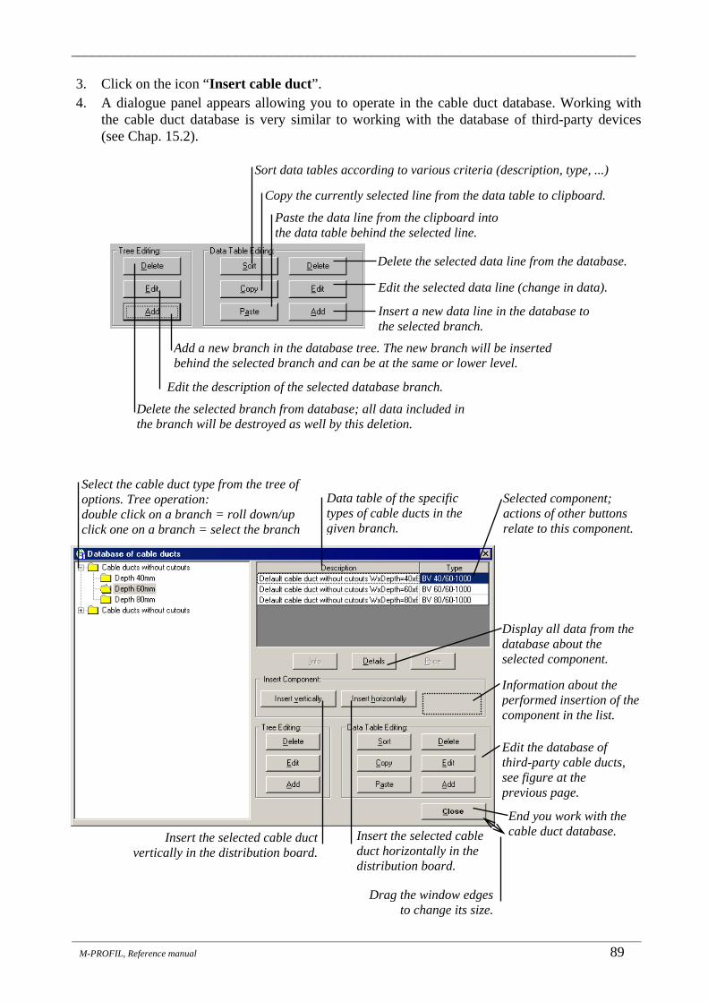
_______________________________________________________________________________
_______________________________________________________________________________________________________________________
M-PROFIL, Reference manual 89
3. Click on the icon “Insert cable duct”. 4. A dialogue panel appears allowing you to operate in the cable duct database. Working with
the cable duct database is very similar to working with the database of third-party devices (see Chap. 15.2).
Copy the currently selected line from the data table to clipboard.
Sort data tables according to various criteria (description, type, ...)
Paste the data line from the clipboard into the data table behind the selected line.
Delete the selected data line from the database.
Select the cable duct type from the tree of options. Tree operation: double click on a branch = roll down/up click one on a branch = select the branch
Edit the selected data line (change in data).
Data table of the specific types of cable ducts in the given branch.
Insert a new data line in the database to the selected branch.
Delete the selected branch from database; all data included in the branch will be destroyed as well by this deletion.
Selected component; actions of other buttons relate to this component.
Add a new branch in the database tree. The new branch will be inserted behind the selected branch and can be at the same or lower level.
Display all data from the database about the selected component.
Edit the description of the selected database branch.
Insert the selected cable duct horizontally in the distribution board.
End you work with the cable duct database. Insert the selected cable duct
vertically in the distribution board.
Edit the database of third-party cable ducts, see figure at the previous page.
Information about the performed insertion of the component in the list.
Drag the window edges to change its size.

_______________________________________________________________________________
_______________________________________________________________________________________________________________________
90 M-PROFIL, Reference Manual
3a. Creating a new branch in the database tree: The procedure is completely identical to the one applied with the database of third-party equipment, see Chap. 15.2.1 item 3a.
3b. Renaming a branch in the database tree: The procedure is completely identical to the one
applied with the database of third-party equipment, see Chap. 15.2.1 item 3b.
3c. Deleting a branch in the database tree: The procedure is completely identical to the one applied with the database of third-party equipment, see Chap. 15.2.1 item 3c.
4a. Inserting a new cable duct in the database to a given branch:
a) Select the branch in the database tree, to which you want to insert the desired component. In case this branch does not exist, you need to create it by following the instructions provided under 3a. It is advisable for this branch to be the end branch of the tree, but it is not a must.
b) Click on the Add button in the Data Table Editing group. A dialogue panel will open, in which you enter all required data defining the component:
c) Close the dialogue panel by clicking OK. The new component will be added to the end of
the data table.
4b. Inserting a new component in the database to a given branch by copying an existing component: The procedure is completely identical to the one applied with the database of third-party equipment, see Chap. 15.2.1 item 4b.
Cable duct description - text, which will appear in the breakdown list of components (type, basic parameters, manufacturer, ...), max. 50 characters.
Type according to the manufacturer (max. 20 characters). It is used for identification of the device and for the duplicity test. It must be unique within the entire database !!
Catalogue price for one piece of the component (to calculate the total project price). The price specified here will not be adjusted any further.
Definition of cable duct dimensions, click on the picture to enlarge it.
Cable duct dimensions, other dimensions than those specified here cannot be inserted in the Profi Plus distribution boards.
One cable duct segment in the distribution board cannot be longer than the value specified here. When the breakdown list is generated, the length of the individual segments of the same type will be added together and the quantity of the maximum length segments will be determined.
Whether the cable duct has cutouts for cable branch s – see figure.

_______________________________________________________________________________
_______________________________________________________________________________________________________________________
M-PROFIL, Reference manual 91
4c. Editing the data of an existing cable duct in the database:
a) Select the branch in the database tree where the component is located, which you want to edit. b) Select the component to be edited in the data table. c) Click on the Edit button in the Data Table Editing group. The same dialogue will appear
as the one opening when defining a new component (see procedure under item 4a), with the current data about the edited component being pre-filled in the particular fields. These fields can be edited in any desired way. Edit the data. Close the dialogue panel by clicking OK. The data will be recorded in the database. CAUTION: the data concerned will be changed in the database; however, the data in the already inserted pieces used in distribution board will not be edited!
4d. Deleting a cable duct from the database:
a) Select the branch in the database tree where the component is located, which you want to delete. b) Select the component in the data table, which you want to delete. c) Click on the Delete button in the Data Table Editing group. The system will ask you
whether you are sure you want to delete the selected component from the database. If you confirm the deletion, the component will be deleted from the database (CAUTION - it will not be deleted from the list of cable ducts selected for this distribution board!!)
4e. Sorting currently displayed database table. The procedure is completely identical to the one
applied with the database of third-party equipment, see Chap. 15.2.1 item 4e.
5. Click Close to exit your work with the cable duct database. Note: Data files of the user-defined database of cable ducts are located in the \DATA\VLASTNI\KKAN directory. We strongly recommend you to make a backup of this directory as not to lose the definitions in case of any system failure. For backup of the entire M-PROFIL system installation see Chap. 2.4.
14.2 Inserting a horizontal cable duct from the database in the distribution board
1. Roll down the project structure tree by clicking on the “+” sign next to the distribution board name. Double click on the “Cable Ducts” branch (the branch is present in the tree only if the Profi Plus or XVTL distribution board system was selected for the given distribution board).
2. The system will check whether a Profi Plus distribution board or an XVTL distribution board with Profi Plus adapter is present. If this is the case, a window with the list of the already inserted cable ducts appears.
3. Click on the icon “Insert cable duct”. 4. A dialogue panel appears allowing you to work with the cable duct database. Set the branch in
the database tree where the desired group of cable ducts is located (database tree operation is identical to the one used with the database of devices, for more details see Chap. 15.1). In case this branch does not exist, you need to create it (see Chap. 14.1).

_______________________________________________________________________________
_______________________________________________________________________________________________________________________
92 M-PROFIL, Reference Manual
5. Select the cable duct, which you want to insert, in the data table. Only the main information is shown in the data table. If you want to see all information, click on the Details button below the data table. In case the cable duct does not exist yet, it must be inserted into the database (see Chap. 14.1).
6. Click Insert horizontally.
• If the edited distribution board is a Profi Plus (surface or floor mounted), or XVTL (with rear Profi Plus adapter), the following dialogue panel appears:
• Enter the required number of horizontal cable ducts, the height of the first cable duct
and the distance between cable ducts (the default values are determined automatically based on the number of mounting rails).
• Enter the cable duct shortening left and right. If no shortening is defined, the cable duct will run across the entire distribution board.
• Click OK. The selected duct will be inserted in the list and displayed in the distribution board dimensional drawing. If the inserted cable duct is not displayed in the dimensional drawing, please check whether the distribution board frame component view is enabled (see Chap. 5.10).
The cable duct will be mounted to C profile. The same procedure as with flush-mounted Profi Plus distribution boards – see below.
Bulk insertion of a group of cable ducts mounted to BPZ-CDB fixing support (fixing supports and reinforcing C profiles, as appropriate, are ordered automatically).
Cable duct to be shortened left and right – in order to create space for a vertical cable duct. If no shortening is defined, the cable duct will run across the entire distribution board.
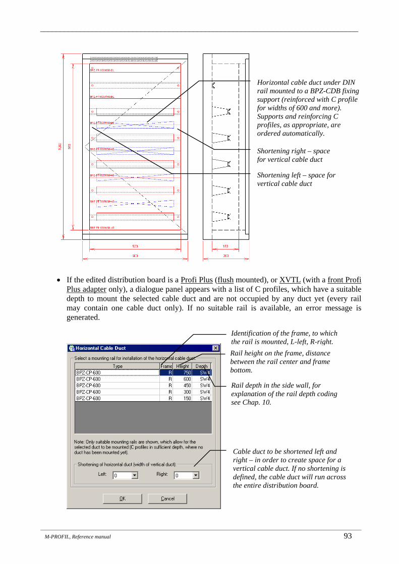
_______________________________________________________________________________
_______________________________________________________________________________________________________________________
M-PROFIL, Reference manual 93
• If the edited distribution board is a Profi Plus (flush mounted), or XVTL (with a front Profi
Plus adapter only), a dialogue panel appears with a list of C profiles, which have a suitable depth to mount the selected cable duct and are not occupied by any duct yet (every rail may contain one cable duct only). If no suitable rail is available, an error message is generated.
Rail height on the frame, distance between the rail center and frame bottom.
Identification of the frame, to which the rail is mounted, L-left, R-right.
Rail depth in the side wall, for explanation of the rail depth coding see Chap. 10.
Cable duct to be shortened left and right – in order to create space for a vertical cable duct. If no shortening is defined, the cable duct will run across the entire distribution board.
Shortening right – space for vertical cable duct
Shortening left – space for vertical cable duct
Horizontal cable duct under DIN rail mounted to a BPZ-CDB fixing support (reinforced with C profile for widths of 600 and more). Supports and reinforcing C profiles, as appropriate, are ordered automatically.

_______________________________________________________________________________
_______________________________________________________________________________________________________________________
94 M-PROFIL, Reference Manual
• Select the rail where you want to mount the cable duct. • Specify how much the cable duct should be shortened at the left and at the right. If no
shortening is defined, the cable duct will run across the entire distribution board. • Click OK. The selected duct will be inserted in the list and displayed in the distribution
board dimensional drawing. If the inserted cable duct is not displayed in the dimensional drawing, please check whether the distribution board frame component view is enabled 5.10).
14.3 Inserting a vertical cable duct from the database in the distribution board
1. Roll down the project structure tree by clicking on the “+” sign next to the distribution board name. Double click on the Cable Ducts branch (the branch is present in the tree only if the Profi Plus or XVTL distribution board system was selected for the given distribution board).
2. The system will check whether a Profi Plus distribution board or an XVTL distribution board with Profi Plus adapter is present. If this is the case, a window with the list of the already inserted cable ducts appears.
3. Click on the icon Insert cable duct. 4. A dialogue panel appears allowing you to work with the cable duct database. Set the branch in
the database tree where the desired group of cable ducts is located (database tree operation is identical to the one used with the database of devices, for more details see Chap. 15.1). In case this branch does not exist, you need to create it (see Chap. 14.1).
5. Select the cable duct, which you want to insert, in the data table. Only the main information is shown in the data table. If you want to see all information, click on the Details button below
Shortening right – space for vertical cable duct
Shortening left – space for vertical cable duct
Horizontal cable duct mounted to a C profile (the C profile must be inserted before the cable duct is inserted).

_______________________________________________________________________________
_______________________________________________________________________________________________________________________
M-PROFIL, Reference manual 95
the data table. In case the cable duct does not exist yet, it must be inserted into the database (see Chap. 14.1).
6. Click Insert vertically. A dialogue panel appears, showing a list of mounting rails, which are suitable to mount the selected cable duct and are not crossed by any vertical cable duct. If no suitable rail is available, an error message is generated.
7. Select the position of the cable duct on the distribution board frame: left, or right. 8. Select the mounting method: either to shortened DIN rails using a KKW cable duct angle or to
BPZ-CDB fastening support (this option is offered only for Profi Plus distribution boards (surface or floor mounted) and for XVTL distribution boards (with rear Profi Plus adapter)). The offered range of suitable mounting rails is adjusted according to the mounting method selected.
9. Select two different rails, between which the vertical cable duct will be mounted, and click OK. The selected duct will be inserted in the list and will appear in the dimensional drawing of the distribution board. If the inserted duct is not displayed in the dimensional drawing, please check whether the distribution board frame component view is enabled (see Chap. 5.10).
Insert cable duct. Erase cable duct.
The list of the inserted cable ducts is always sorted from top to bottom; first the vertical cable ducts, then the horizontal ones; if there are two frames in the distribution board, the left frame is first, then the right one.
Rail height on the frame, distance between the rail center and frame bottom.
Identification of the frame, to which the rail is mounted L-left, R-right.
Rail depth in the side wall, for explanation of the rail depth coding see Chap. 10. List of suitable rails, where the vertical duct can start.
List of suitable rails, where the vertical duct can end.

_______________________________________________________________________________
_______________________________________________________________________________________________________________________
96 M-PROFIL, Reference Manual
Depiction of cable ducts in the dimensional drawing (here surface mounted Profi Plus distribution board):
Identification of rails, on which the cable duct is mounted (vertical - 2 rails, horizontal - 1 rail); rail height, frame identification: [L] - left, [R] – right.
Method of cable duct mounting: VER – vertically [L] - left, [R] - right, HOR - horizontally.
Cable duct segment length. When the breakdown list is generated, the length of the individual segments of the same type will be added together and the quantity of the maximum length segments will be determined.
Note: M-PROFIL does not offer the option to hide invisible edges; the devices, cover plates and blinds are “transparent”.
Horizontal cable duct.
Vertical cable duct left
Vertical cable duct right

_______________________________________________________________________________
_______________________________________________________________________________________________________________________
M-PROFIL, Reference manual 97
14.4 Erasing a cable duct
1. Roll down the project structure tree by clicking on the “+” sign next to the distribution board name. Double click on the “Cable Ducts” branch (the branch is present in the tree only if the Profi Plus or XVTL distribution board system was selected for the given distribution board).
2. The system will check whether a Profi Plus distribution board or an XVTL distribution board with Profi Plus adapter is present. If this is the case, a window with the list of the already inserted cable ducts appears.
3. Click on the line containing the cable duct, which you want to erase. 4. Click on the icon “Erase cable duct”. The selected cable duct will be deleted from the
list of the inserted cable ducts and the dimensional drawing will be repainted accordingly. The pointed will be set to the previous duct. Click on the icon “Erase cable duct” repeatedly to delete all ducts from the list.
5. Close the window with the list of cable ducts by clicking on the X in the upper right corner of the window or by pressing Esc.
Tip: If you click with your right mouse button in the list of the cable ducts, a context menu will appear allowing you to make a quick function selection (erase, insert) and to apply it to the selected line.

_______________________________________________________________________________
_______________________________________________________________________________________________________________________
98 M-PROFIL, Reference manual
15. Fitting Devices on Distribution Boards _______________________________________________
The following rules apply in the M-PROFIL system when you fit devices:
1. The devices are selected from fixed databases supplied with the system (Moeller devices) on one hand, and from the user-defined databases created continuously by the user, on the other hand.
2. Devices from the databases are inserted in the list of the selected devices. A continuous test of how the devices are fitted on the distribution board rails is carried out simultaneously (provided the distribution board has already been defined). This continuous test is based on comparing the number of modules (1 module = 17.5 mm), which are available on the distribution board rails, with the number of modules, which are occupied by the so-far selected devices.
3. The selected devices can be fitted on the distribution board rails at any moment (provided the distribution board has already been defined). All mechanical relations are taken into account during this procedure (mounting rail type, installation depth, …).
4. The list of the already selected devices can be modified in any manner (add/remove devices, change the quantities, …).
15.1 Database of Moeller devices The database of devices is a set comprising installation devices (formerly F&G devices), devices for industrial applications (power circuit protection, contactors, automation, etc.) and Xcomfort modular devices that are included in the catalogues for individual countries for the current year. The database always contains the current offer. Items that are not included in the offer (devices and accessories of other manufacturers, terminal blocks, etc.) are to be inserted from the user-defined databases that are created and filled with data by the user (see Chap. 15.2, 15.3). The devices are divided into logical groups and subgroups according to their function and properties and are arranged into a tree structure database. The following is included in database for every device:
• Information about the device - electrical, mechanical, in the scope of the catalogue sheets, • Device dimensions (picture with dimension figures), • Device photo • Front view of the device, which will then be inserted/fitted on the distribution board rails, • Electric wiring diagram, • Link to the price list - determination of the device catalogue price, • Link to the particular components in case of a set (assembly).
The principle of component search in the database is explained in the following example: You need to find the device: Residual current device resistant to impulse current of 250 A, 4-pole type, rated current In=25 A, rated residual current Idn=0.1 A.
1. Roll down the project structure tree by clicking on the “+” sign next to the distribution board name. Double click on the “Devices” branch (this branch is always present in the tree). A window with the list of the already inserted devices appears.

_______________________________________________________________________________
_______________________________________________________________________________________________________________________
M-PROFIL, Reference Manual 99
2. Click on the Database of Installation Devices icon. • Note: In the event that an Xcomfort device or a device for an industrial
application is required, click on the icon of the respective database. The further procedure is identical.
3. A dialogue panel opens up for operations with the database of installation devices. The required device type is to be found out in the tree structure of the database. The rules for moving along the tree are the same as for the directory tree of Windows Explorer: • An item beginning with the “+” sign is rolled up (it includes additional sub-branches,
which are not shown). To roll down the item menu (and to view its sub-branches), double click on the respective item (or click on the “+” sign).
• An item beginning with the “-” sign is rolled down (all its sub-branches are shown on the screen). To roll up the item menu double click the respective item (or click on the “-” sign).
• Click on any branch once to view more detailed information about the branch in the items on the right side from the tree.
Now you want to find your device - the residual current device (resistant to impulse current of 250 A, 4-pole type, rated current In=25 A, rated residual current Idn=0.1 A):
• Double click on branch “Residual current devices up to 80A, PF7 series” - tree will roll down. • Double click on the branch “Impact resistance Ir=250 A, AC type” - the tree will roll down. • Click once on the “Residual current device Ir=250A, AC type, 4-pole” branch - now you are
already located on the end sub-branch of the tree and the table of the available devices appears. The figures at the top right part show a view of the device including its dimensions, a photo and the wiring diagram.
Dimensional drawing. Click on this picture to enlarge it.
Wiring diagram. Click on the picture to enlarge it.
Select device type from the tree of options.
Selected branch (end branch in of the database); information on the right relate to this branch
Table of specific device types in the given branch.
Click on the Info button to view legend with explanation of abbreviations used in the table header. Selected component; actions of other buttons relate to this component.
Price of the selected
Display all data about the selected component.
Information about the selected branch of the database tree from the catalogue sheet.
Insert the specified quantity of the selected device in the list of the selected devices.
Exit working with the database. Quantity of the selected device,
which is to be inserted in the list.
Information about insertion.
Illustrative photo of the device. Click on the picture to enlarge it.
Drag the windows edges to change its size.
Search component by type designation or order number (see Chap. 17).
Activation of the accessories database explorer (see Chap. 16.1).

_______________________________________________________________________________
_______________________________________________________________________________________________________________________
100 M-PROFIL, Reference manual
• Click on the photo, the picture with the device or the diagram to enlarge it and to be able to read the texts better. Click OK to reduce the figure again.
• If you do not know what the data and abbreviations in the table header mean, click Info. A dialogue panel will open showing you information about the device (catalogue sheet) including a legend for the abbreviations.
4. Click on the line where In=25 (rated current in A) and Idn=0.01 (rated residual current in A). For such selected device it is possible to: • Determine its price after clicking on the Price button:
• Find out more detailed information about it from the catalogue sheet after clicking on the Info button:
You can obtain a description of general properties applicable jointly for the whole group by clicking first on the superior branch (in your case the “Residual current devices up to 80A, PF7 series” branch) and then the Info button.
Legend with explanation of abbreviations used in the table header.
Description of device (or device group) properties from the catalogue sheet.
Settings of discounts and surcharges for the individual component groups see Chap. 21.5.

_______________________________________________________________________________
_______________________________________________________________________________________________________________________
M-PROFIL, Reference Manual 101
• Display all data from the database, which are available for the selected device, after clicking on the Details button:
• Insert the number of pieces of the device in the list of the selected devices. The number
of pieces is set in the Quantity field in the bottom part of the dialogue panel. The device with the required quantity will be inserted in the list after you click on the “Insert in List” button.
5. Set the Quantity field to 1 and click on the “Insert in List” button 6. A dialogue panel will open, in which you enter the tag for the inserted devices. The tag is
composed of some text and number, such as FI1. In case you are inserting several pieces of the device, the number will be increased step by step by the Numbering Interval. • Click on the “Add Tags” button (or press Enter) to insert the device in the list and to
associate the specified tag with this device. The tag can be modified at a later point in time. • Click on the “WITHOUT Tags” button (or press Esc) to insert the device in the list
without any tag. The tag can be added at a later point in time. • Note: The entry of tags can be overridden permanently by means of the Options function
(see Chap. 26.5).
Information from the catalogue sheet.
All database information about the device.
Click on the picture to enlarge it.
It is useful only when more than one piece of a device is inserted. All inserted pieces will be marked consecutively as FI1, FI2, ...
Tag settings for the inserted devices.
No tag will be attached to the inserted device. The tag can be added at any later point in time through a separate function.
The specified tag will be attached to the component.

_______________________________________________________________________________
_______________________________________________________________________________________________________________________
102 M-PROFIL, Reference manual
7. Double click on the branch “Residual current devices up to 80A, PF7 series” - the tree behind the branch will roll up and will be restored to the original state.
8. If you want to add some accessories to the device, which will not be fitted on the rail (such as auxiliary contacts installed inside the device or lever lock etc.), click on the Accessories button, thus activating the accessories database explorer (see Chap. 17.1). These accessories have no connection to the currently inserted device and its editing will not result in any modification of these accessories. This list of accessories selected in this manner can be edited under the Accessories branch (see Chap. 17.3, 17.4).
9. Repeat steps 3 - 6 until you insert all required devices in the list. Move the database window to view continuously updated information about the contents of the list of the selected devices.
10. Click Close to finish you work with the database and exit. 11. Close the window with the list of the selected devices by clicking on the X in the right corner
or by pressing Esc. Tip for experienced designers: If you are familiar with the offered devices of Moeller and it is quicker and more comfortable for you to search a device based on the type designation (rather than based on its properties), use the Search button (see Chap. 18). Note: If there is a distribution board already, the continuous fitting test is carried out automatically when the device is inserted in the list. By means of the Device AutoFit function (Chap. 15.11.1), it is possible to fit the devices on the distribution board rails All relations and connections are taken into account during this procedure.
15.1.1 Command and signalling devices fitted on the door The command and signalling devices represent a specific category of devices:
• Every device is constituted as an assembly of a number of partial components (control heads, plate, contact module, …).
• The devices are fitted on the distribution board door. For these reasons, the command and signalling devices are inserted through a separate function.
1. Roll down the project structure tree by clicking on the “+” sign next to the distribution board name. Double click on the “Devices” branch (this branch is always present in the tree). A window with the list of the already inserted devices appears.
2. Click on the icon Command and signalling devices fitted on the door. A dialogue panel will open, in which you specify the device.
3. Select the Device type from the list of the available types (such as “Push button, flush mounted, complete"). The device type determines the dimensions and appearance of the control element as well as the categories, from which the individual components can be selected. The accessibility of buttons for the individual categories will be set accordingly (Heads, Contact modules, …).

_______________________________________________________________________________
_______________________________________________________________________________________________________________________
M-PROFIL, Reference Manual 103
4. Specify the individual components forming the assembly.
• Click on the Head button. A dialogue panel will subsequently open, in which you select the required component in the list of those available. Then click Insert. The component will be inserted in the assembly (if you drag the dialogue panel aside, you can check the list of components). Tip: double click on the respective line to insert the selected component quickly.
The device type determines the dimensions and appearance of the control element and the categories, from which the components can be selected.
Individual component categories. Click on the button to view the list of possible components in the given category. Only categories suitable for the given component type are enabled.
List of selected components for the selected type of device (list of assembly components).
Quantity (= total number of assemblies) of the device, which is to be inserted in the list of the selected devices.
Erase the selected component from the list.
Category name
List of components in the selected category.
Insert the selected component in the assembly (also double click on the selected line).
Close the dialogue panel (also press Esc).
Dimensions of the dialogue panel can be adjusted by dragging its edges.

_______________________________________________________________________________
_______________________________________________________________________________________________________________________
104 M-PROFIL, Reference manual
• Insert all required components from this category. Click Close to close the dialogue panel (or press Esc).
• Similarly insert components from other available categories (Contact modules, Plates, Keypad panels, …). Only categories suitable for the given component type are enabled.
• Caution: the program does not check for suitability, completeness, quantity or mutual interactions of the individual components !! Several components can be selected from each category, some of them can be inserted more times - such as contact modules; in other categories it may happen that no component will be inserted. The user is responsible for logical correctness of the design.
• The full range of all elements is available on the Accessories branch (see Chap. 17); there is no link between the components inserted on the accessories branch and these components cannot be fitted on the distribution board door.
• An already selected component can be deleted from the list after clicking on Erase.
5. Set the Number of inserted pieces (= total number of assemblies) of the device, which is to be inserted in the list of the selected devices.
6. Click OK. A dialogue panel will then open, in which you enter the tag for the inserted devices. The tag is composed of some text and number, such as TA1. In case you are inserting several pieces of the device, the number will be increased step by step by the Numbering Interval.
• Click on the “Add Tags” button (or press Enter) to insert the device in the list and to associate the specified tag with this device. The tag can be modified at a later point in time.
• Click on the “WITHOUT Tags” button (or press Esc) to insert the device in the list without any tag. The tag can be added at a later point in time.
• Note: The entry of tags can be overridden permanently by means of the Options function (see Chap. 26.5).
7. Activate this function repeatedly to insert all the required components. 8. The individual components of an existing assembly can be modified afterwards by
means of the icon “Modify assembly of command and signalling element”.
15.2 Database of third-party devices (devices from other manufacturers) Devices, which are not found in the database (primarily devices from other manufacturers), are called Third-party devices. All data, which are otherwise included in the database (dimensions, rail, description, …) must be specified by the user for these devices. Thereafter it is possible to insert such a device in the list of the selected devices. Such a device has the same properties as any other Moeller device with the only difference that it does not have any order number and its price is entered directly by the user (it is not taken over from the pricelist). Step by step, the user creates a database of third-party devices, which remains the same regardless of the currently edited distribution board.
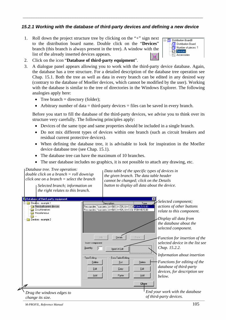
_______________________________________________________________________________
_______________________________________________________________________________________________________________________
M-PROFIL, Reference Manual 105
15.2.1 Working with the database of third-party devices and defining a new device
1. Roll down the project structure tree by clicking on the “+” sign next to the distribution board name. Double click on the “Devices” branch (this branch is always present in the tree). A window with the list of the already inserted devices appears.
2. Click on the icon “Database of third-party equipment”. 3. A dialogue panel appears allowing you to work with the third-party device database. Again,
the database has a tree structure. For a detailed description of the database tree operation see Chap. 15.1. Both the tree as well as data in every branch can be edited in any desired way (contrary to the database of Moeller devices, which cannot be modified by the user). Working with the database is similar to the tree of directories in the Windows Explorer. The following analogies apply here: • Tree branch = directory (folder); • Arbitrary number of data = third-party devices = files can be saved in every branch.
Before you start to fill the database of the third-party devices, we advise you to think over its structure very carefully. The following principles apply: • Devices of the same type and same properties should be included in a single branch. • Do not mix different types of devices within one branch (such as circuit breakers and
residual current protective devices). • When defining the database tree, it is advisable to look for inspiration in the Moeller
device database tree (see Chap. 15.1). • The database tree can have the maximum of 10 branches. • The user database includes no graphics, it is not possible to attach any drawing, etc.
Database tree. Tree operation: double click on a branch = roll down/up click one on a branch = select the branch
Selected branch; information on the right relates to this branch.
Selected component; actions of other buttons relate to this component.
Display all data from the database about the selected component.
End your work with the database of third-party devices.
Data table of the specific types of devices in the given branch. The data table header cannot be changed; click on the Details button to display all data about the device.
Function for insertion of the selected device in the list see Chap. 15.2.2.
Functions for editing of the database of third-party devices, for description see below.
Information about insertion
Drag the windows edges to change its size.

_______________________________________________________________________________
_______________________________________________________________________________________________________________________
106 M-PROFIL, Reference manual
3a. Creating a new branch in the database tree: E.g. you need to add different (sub)branches to the “Devices - example 1” branch in order to obtain a tree with the configuration as shown in the figure.
a) First of all, you create the “Switch-
disconnectors” branch, which is on the same level as the “Circuit-breakers”. Double click on the “Devices - example 1” branch to roll down the tree. Select the “Circuit-breakers” branch (one click) - newly created branches are always inserted behind (under) the currently selected branch.
b) Click on the Add button in the Tree Editing group. A dialogue panel will open, in which you type the name of the new branch (i.e. “Switch-disconnectors” and set the level of the new inserted branch to Same (= the same level as the currently selected branch):
Close the dialogue panel by clicking OK. The new branch will be inserted. c) Now add the “Nominal current …” sub-branches, which are on the level being one lower.
Select the newly inserted “Switch-disconnectors” branch (one click). d) Click on the Add button in the Tree Editing group. A dialogue panel will open, in which
you type the name of the new branch (i.e. “Nominal current up to 64 A” and set the level of the new inserted branch to One lower (= another/lower level behind the currently selected branch). Close the dialogue panel by clicking OK. The new branch will be inserted.
e) Select the newly inserted “Nominal current up to 64 A” branch (one click).
Nominal current up to 120 A
Devices Example 2
Nominal current up to 64 A
Switch disconnectors
Circuit-breakers
Residual current devices
Devices Example 1
Newbranches
Name (description) of the new inserted branch, any text max. 50 characters.
Level of the new inserted branch with respect to the currently selected branch.
Copy the currently selected line from the data table to clipboard.
Sort data table according to various criteria (description, type, ...).
Paste the data line from the clipboard into the data table behind the selected line.
Delete the selected data line from the database.
Edit the selected data line (change in data).
Insert a new data line in the database to the selected branch.
Delete the selected branch from database; all data included in the branch will be destroyed as well by this deletion.
Insert a new branch in the database tree. The new branch will be inserted behind the selected branch and can be at the same or lower level.
Edit the description of the selected database branch.

_______________________________________________________________________________
_______________________________________________________________________________________________________________________
M-PROFIL, Reference Manual 107
f) Click on the Add button in the Tree Editing group. A dialogue panel will open, in which you type the name of the new branch (i.e. “Nominal current up to 120 A” and set the level of the new inserted branch to Same (= the same level as the currently selected branch). Close the dialogue panel by clicking OK. The new branch will be inserted.
3b. Renaming a branch in the database tree: You need to rename the “Devices - example 1” branch
to “Switching devices”:
a) Select the branch in the database tree, the name of which you want to change. b) Click on the Edit button in the Tree Editing group. A dialogue panel will open, in which
you type the new name of the branch. Close the dialogue panel by clicking OK. The branch will be renamed. Note: the branch level cannot be modified by editing, the branch must be deleted and created again at the new desired level.
3c. Deleting a branch in the database tree: E.g. you need to delete the “Devices - Example 2”
branch including all its sub-branches and including all data contained in the branch and the sub-branches.
a) Select the branch in the database tree, which you want to delete. b) Click on the Delete button in the Tree Editing group. Due to the irreversible nature of the
performed operation, the system asks:
If you answer by clicking Yes, the selected branch will be deleted including all its sub-branches and including all data contained in the branch and the sub-branches. The effect of this operation cannot be undone in any manner.
4a. Inserting a new device in the database to a given branch: E.g. you need to add the device “S-
series switch-disconnector, 3+N pole, In=40 A, S40/3+N type” in the “Switch-disconnectors” - “Nominal current up to 63 A” branch.
a) Select the branch in the database tree, to which you want to insert the desired device. In
case this branch does not exist, you need to create it by following the instructions provided under 3a. It is advisable for this branch to be the end branch of the tree, but it is not a must.
b) Click on the Add button in the Data Table Editing group. A dialogue panel will open, in which you enter all required data defining the device (the default values correspond to the typical 1-pole low-voltage circuit-breaker):

_______________________________________________________________________________
_______________________________________________________________________________________________________________________
108 M-PROFIL, Reference manual
c) Close the dialogue panel by clicking OK. The new device will be added to the end of the
data table.
4b. Inserting a new device in the database to a given branch by copying an existing device: E.g. you need to add another device “S-series switch-disconnector, 3+N pole, In=63 A, S63/3+N type” in the “Switch-disconnectors” - “Nominal current up to 64 A” branch. As you can see all device parameters are identical with those of the device inserted in item 4a, except for the differing nominal current.
a) Select the branch in the database tree, to which you want to insert the new device (in your
case the “Switch-disconnectors” - “Nominal current max. 63 A” branch). A list of already defined devices will be shown in the data table.
b) Select the device in the data table, which you want to copy. c) Click on the Copy button in the Data Table Editing group. The selected line will be
copied to clipboard. d) Select the device in the data table, behind which you want the line copy to be inserted. e) Click on the Paste button in the Data Table Editing group. The line will be pasted from
the clipboard into the data table behind the currently clicked line. f) Modify the data in the selected line - see procedure described in item 4c.
4c. Modifying (editing) data of an existing device in the database: E.g. you need to modify the
copy created by the procedure under item 4b:
a) Select the branch in the database tree where the device is located, which you want to modify.
b) Select the device in the data table, which you want to modify.
Device dimensions, for geometric meaning see picture on the right.
Definition of dimensions for third-party device, click on the image to enlarge it. Device description - text, which will appear in the breakdown list of components (type, basic parameters, manufacturer, ...), max. 50 characters.
Catalogue price for one piece of the device (to calculate the total project price). The price specified here will not be adjusted any further.
Type according to the manufacturer (max. 20 characters). It is used for identification of the device and for the duplicity test. It must be unique within the entire database.
Power lose – heat emitted from the device at the rated current. Will be used to calculate the temperature rise in the distribution boards (see Chap. 19).

_______________________________________________________________________________
_______________________________________________________________________________________________________________________
M-PROFIL, Reference Manual 109
c) Click on the Edit button in the Data Table Editing group. The same dialogue will appear as the one opening when defining a new device (see procedure under item 4a), with the current data about the edited device being pre-filled in the particular fields. These fields can be edited in any desired way. Edit the data. Close the dialogue panel by clicking OK. The data will be recorded in the database. CAUTION: the data concerned will be changed in the database of third-party devices, however, the data in the already inserted pieces of the device used in distribution board will not be edited !
4d. Deleting a device from the database:
a) Select the branch in the database tree where the device is located, which you want to delete.
b) Select the device in the data table, which you want to delete. c) Click on the Delete button in the Data Table Editing group. The system will ask you
whether you are sure you want to delete the selected device from the database. If you confirm the deletion, the device will be deleted from the database (CAUTION - it will not be deleted from the list of the selected devices !!)
4e. Sorting the currently displayed database table. Sorting of the database contents can be done in
alphabetical order according to various criteria. The internal Windows algorithm is used, which distinguishes between lower-case and upper-case letters. In lower system versions, this algorithm sorts characters with Czech diacritics all the way to the end of the alphabet.
a) Select the branch in the database tree, which contains the data table you want to sort (the
table must include at least two devices in order for the function to make any sense. b) Click on the Sort button in the Data Table Editing group. The system will ask you what
criterion should be used to sort the table:
c) Select the required criterion and close the dialogue panel by clicking OK. The table will be
sorted. The sorting remains saved permanently. Note: sorting of large tables can take a longer time if performed on slower computers.
5. Click Close to finish you work with the database of third-party equipment.
Note: Data files of the user-defined database of third-party devices are located in the \DATA\VLASTNI\CIPR directory. We strongly recommend you to make a backup of this directory as not to lose the definitions in case of any system failure. For backup of the entire M-PROFIL system installation see Chap. 2.3.

_______________________________________________________________________________
_______________________________________________________________________________________________________________________
110 M-PROFIL, Reference manual
15.2.2 Inserting a third-party device in the list
1. Roll down the project structure tree by clicking on the “+” sign next to the distribution board name. Double click on the “Devices” branch (this branch is always present in the tree). A window with the list of the already inserted devices appears.
2. Click on the icon “Database of third-party equipment”. 3. Select the branch in the database tree where the desired group of devices is located (database
tree operation is identical to the one used with the database of devices, for more details see Chap. 15.1). In case this branch does not exist yet, you need to create it (see Chap. 15.2.1).
4. Select the device in the data table, which you want to insert. Only the main information about the device is shown in the data table. If you want to see all information, click on the Details button below the data table. In case the desired device does not exist yet, it must be inserted into the database (see Chap. 15.2.1).
5. Set the Quantity to the required number of pieces of the device, which you want to insert. 6. Click on the button “Insert in List”. 7. A dialogue panel will open, in which you enter the tag for the inserted devices, similarly as
when inserting Moeller devices, see Chap. 15.1, item 6. The entry of tags can be overridden permanently by means of the Options function (see Chap. 26.5).
8. Repeat steps 3 - 7 until you insert all the required devices. Move the database window to view continuously updated information about the contents of the list of the selected devices.
9. Click Close to finish you work with the database of third-party equipment. 10. Close the window with the list of the selected devices by clicking on the X in the right corner
or by pressing Esc.
Database tree. Tree operation: double click on a branch = roll down/up click one on a branch = select the branch.
Display all data from the database about the selected component.
End your work with the database of third-party devices.
Data table of the specific types of devices in the given branch. The data table header cannot be changed; click on the Details button to display all data about the device.
Functions for editing of the database of third-party devices, see Chap. 15.2.1.
Insert the specified quantity of the selected component in the list of the selected devices.
Quantity of the selected device, which is to be inserted in the list.
Selected component; actions of other buttons relate to this component.
Function for insertion of the selected device in the list.
Information about insertion.
Drag the window edges to change its size.

_______________________________________________________________________________
_______________________________________________________________________________________________________________________
M-PROFIL, Reference Manual 111
Note: If there is a distribution board already, a continuous fitting test is carried out automatically when the device is inserted in the list. By means of the Device AutoFit function (Chap. 15.11.1), it is possible to fit the devices on the distribution board rails All mechanical relations are taken into account during this procedure.
15.3 Inserting terminal blocks Terminal blocks are special “third-party devices” having a special shape. Since the offers of Moeller do not include terminal blocks, the terminal block database is created continuously by the user depending on what types from which manufacturers he/she is used to employ. All required data must be entered when entering every terminal block type in the database (dimensions, rail, description, …). Terminal blocks from the database can be subsequently inserted in the list of the selected devices. Such inserted device has the same properties as any other Moeller device with the only difference that it does not have any order number and its price is entered directly by the user (it is not taken over from the pricelist). Step by step, the user creates a database of terminal blocks, which remains the same regardless of the currently edited distribution board.
15.3.1 Working with the terminal block database and defining new terminal blocks
1. Roll down the project structure tree by clicking on the “+” sign next to the distribution board name. Double click on the “Devices” branch (this branch is always present in the tree). A window with the list of the already inserted devices appears.
2. Click on the icon “Database of terminal blocks”. 3. A dialogue panel appears allowing you to work with the terminal block database. Working
with the terminal block database is very similar to working with the database of third-party devices (see Chap. 15.2.1)
3a. Creating a new branch in the database tree: The procedure is completely identical to the one
applied with the database of third-party equipment, see Chap. 15.2.1 item 3a.
3b. Renaming a branch in the database tree: The procedure is completely identical to the one applied with the database of third-party equipment, see Chap. 15.2.1 item 3b.
3c. Deleting a branch in the database tree: The procedure is completely identical to the one
applied with the database of third-party equipment, see Chap. 15.2.1 item 3c.
Database tree. Tree operation: double click on a branch = roll down/up click one on a branch = select the branch
Selected branch; information on the right relate to this branch.
Data table of the specific types of terminal blocks the given branch. The data table header cannot be changed; click on the Details button to display all data about the device.

_______________________________________________________________________________
_______________________________________________________________________________________________________________________
112 M-PROFIL, Reference manual
4a. Inserting a new terminal block in the database to a given branch:
a) Select the branch in the database tree, to which you want to insert the desired device. In case this branch does not exist, you need to create it by following the instructions provided under 3a. It is advisable for this branch to be the end branch of the tree, but it is not a must.
b) Click on the Add button in the Data Table Editing group. A dialogue panel will open, in which you enter all required data defining the terminal block.
Device dimensions, for geometric meaning see picture on the right.
Definition of terminal-block dimensions, click on the image to enlarge it.
Selected component; actions of other buttons relate to this component. Display all data from the database about the selected component.
Device description - text, which will appear in the breakdown list of components (type, basic parameters, manufacturer, ...), max. 50 characters
End your work with the terminal-block database.
Catalogue price for one piece of the device (to calculate the total project price). The price specified here will not be adjusted any further.
Type according to the manufacturer (max. 20 characters). It is used for identification of the device and for the duplicity test. It must be unique within the entire database !!
Function for insertion of the selected terminal block in the list (the same effect as in the database of third-party devices) see Chap. 15.3.2.
Max. cross-section of the conductor, which can be connected to one terminal, in mm2.
Functions for editing of the terminal-block database (the same effect as in the database of third-party devices see Chap. 15.2.1).
Number of terminals in the terminal block, if it is an assembly.
Information about insertion
Type of rail for mounting; if several types are possible, a separate component must be in the database of devices for every type.
Insert the specified quantity of the selected terminal block in the list of the selected devices.
Quantity of the selected terminal block, which is to be inserted in the list.

_______________________________________________________________________________
_______________________________________________________________________________________________________________________
M-PROFIL, Reference Manual 113
c) Close the dialogue panel by clicking OK. The new device will be added to the end of the data table.
4b. Inserting a new terminal block in the database to a given branch by copying an existing
terminal block: The procedure is completely identical to the one applied with the database of third-party equipment, see Chap. 15.2.1 item 4b.
4c. Editing data for an already existing terminal block in the database:
a) Select the branch in the database tree where the terminal block is located, which you want to edit.
b) Select the terminal block in the data table, which you want to edit. c) Click on the Edit button in the Data Table Editing group. The same dialogue will appear
as the one opening when defining a new terminal block (see procedure under item 4a), with the current data about the edited terminal block being pre-filled in the particular fields. These fields can be edited in any desired way. Edit the data. Close the dialogue panel by clicking OK. The data will be recorded in the database. CAUTION: the data concerned will be changed in the terminal block database, however, the data in the already inserted pieces of the terminal block used in distribution board will not be edited !
4d. Deleting a terminal block from the database:
a) Select the branch in the database tree where the terminal block is located, which you want to delete.
b) Select the terminal block in the data table, which you want to delete. c) Click on the Delete button in the Data Table Editing group. The system will ask you
whether you are sure you want to delete the selected terminal block from the database. If you confirm the deletion, the terminal block will be deleted from the database (CAUTION - it will not be deleted from the list of the selected devices or rails !!)
4e. Sorting the currently displayed database table. Sorting of the database contents can be done in
alphabetical order according to various criteria. The internal Windows algorithm is used, which distinguishes between lower-case and upper-case letters. In lower system versions, this algorithm sorts characters with Czech diacritics all the way to the end of the alphabet.
a) Select the branch in the database tree, which contains the data table you want to sort (the table must include at least two terminal blocks if the function is to make any sense).
b) Click on the Sort button in the Data Table Editing group. The system will ask you what criterion should be used to sort the table:
Sorting by the specified numerical values.
Alphabetical sorting by the specified criterion.
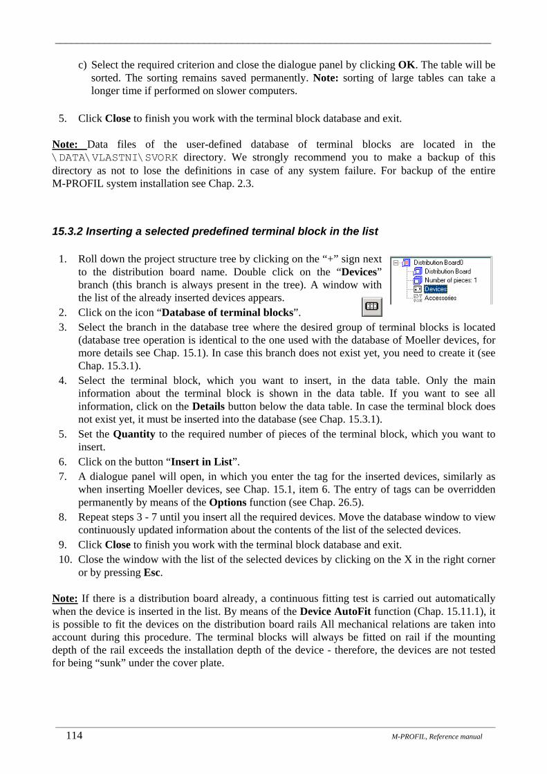
_______________________________________________________________________________
_______________________________________________________________________________________________________________________
114 M-PROFIL, Reference manual
c) Select the required criterion and close the dialogue panel by clicking OK. The table will be sorted. The sorting remains saved permanently. Note: sorting of large tables can take a longer time if performed on slower computers.
5. Click Close to finish you work with the terminal block database and exit.
Note: Data files of the user-defined database of terminal blocks are located in the \DATA\VLASTNI\SVORK directory. We strongly recommend you to make a backup of this directory as not to lose the definitions in case of any system failure. For backup of the entire M-PROFIL system installation see Chap. 2.3.
15.3.2 Inserting a selected predefined terminal block in the list
1. Roll down the project structure tree by clicking on the “+” sign next to the distribution board name. Double click on the “Devices” branch (this branch is always present in the tree). A window with the list of the already inserted devices appears.
2. Click on the icon “Database of terminal blocks”. 3. Select the branch in the database tree where the desired group of terminal blocks is located
(database tree operation is identical to the one used with the database of Moeller devices, for more details see Chap. 15.1). In case this branch does not exist yet, you need to create it (see Chap. 15.3.1).
4. Select the terminal block, which you want to insert, in the data table. Only the main information about the terminal block is shown in the data table. If you want to see all information, click on the Details button below the data table. In case the terminal block does not exist yet, it must be inserted into the database (see Chap. 15.3.1).
5. Set the Quantity to the required number of pieces of the terminal block, which you want to insert.
6. Click on the button “Insert in List”. 7. A dialogue panel will open, in which you enter the tag for the inserted devices, similarly as
when inserting Moeller devices, see Chap. 15.1, item 6. The entry of tags can be overridden permanently by means of the Options function (see Chap. 26.5).
8. Repeat steps 3 - 7 until you insert all the required devices. Move the database window to view continuously updated information about the contents of the list of the selected devices.
9. Click Close to finish you work with the terminal block database and exit. 10. Close the window with the list of the selected devices by clicking on the X in the right corner
or by pressing Esc. Note: If there is a distribution board already, a continuous fitting test is carried out automatically when the device is inserted in the list. By means of the Device AutoFit function (Chap. 15.11.1), it is possible to fit the devices on the distribution board rails All mechanical relations are taken into account during this procedure. The terminal blocks will always be fitted on rail if the mounting depth of the rail exceeds the installation depth of the device - therefore, the devices are not tested for being “sunk” under the cover plate.

_______________________________________________________________________________
_______________________________________________________________________________________________________________________
M-PROFIL, Reference Manual 115
15.4 Inserting N/PE terminals (connecting and branching sleeves) Connecting and branching sleeves are designed to connect N and PE wires or to branch the individual cases, as the case may be. The Moeller offer includes, in addition to full assemblies, a number of partial components allowing you to put together various alternatives of connecting and branching sleeves. It is possible to select the particular alternatives from the database having the tree structure (similarly as devices) and to insert them in the list of selected devices. In case of assemblies, the system automatically searches for the required parts for the purposes of the breakdown list generated at a later point in time. It must be kept in mind that, in most cases, the sleeves are already an integral part of the box in compact distribution boxes. Connecting sleeves from other manufacturers must be defined and inserted as third-party devices (for more details see Chap. 15.2.1).
1. Roll down the project structure tree by clicking on the “+” sign next to the distribution board name. Double click on the “Devices” branch (this branch is always present in the tree). A window with the list of the already inserted devices appears.
2. Click on the icon “Database of N/PE terminals (connecting sleeves)”.
3. A dialogue panel appears allowing you to work with the database of connecting sleeves. Operations in this panel are completely identical with those performed in the Moeller device database (see Chap. 15.1).
Note: The connecting sleeves will always be fitted on rail if the mounting depth of the rail exceeds the installation depth of the device - therefore, the devices are not tested for being “sunk” under the cover plate.
15.5 Loading the list of devices and accessories from a wiring diagram A list of selected devices to be fitted into a distribution board can be created by loading from a data file. This file can be generated by scheme drawing programs (at present e.g. by ElproCAD from Astra92 a.s. Zlín, Czech Republic), ordering systems, or manually using Microsoft Excel. When you load such file, it is no longer necessary to select the devices from the database. Once the
N/PE terminal block (connecting sleeve) as an assembly of partial components.

_______________________________________________________________________________
_______________________________________________________________________________________________________________________
116 M-PROFIL, Reference manual
loading is completed, it is possible to add more components to the list or to adjust the list and use it as the starting point for a distribution board design.
1. Draw a distribution board wiring diagram in a suitable program allowing you to export data to M-PROFIL (such as in ElproCAD from Astra92 a.s. Zlín, Czech Republic), or create a list of devices and accessories in another manner (for data file structure see Chap. 15.5.1). If you use ElproCAD, perform the following operations (for more details see ElproCAD, Reference Manual): • Draw a wiring diagram. The device type must be assigned to every component. These do
not have to include only Moeller devices, it is possible to use devices from any manufacturer.
• Put numbers to the individual wiring diagram components (the function xela-numbering).
• Divide the wiring diagram to the particular distribution board sections (the function xela-set-pole).
• Create a transfer file to be imported to M-PROFIL (the function export_devices). This function is available in ElproCAD version 2.7.2 and higher – please contact the program supplier – the company Astra92 a.s. Zlín, Czech Republic – concerning the implementation of this function into your installation.
2. Start up M-PROFIL. Select the distribution board, into which you want to import the list of devices, as the current one – click on the name of the distribution board in the project structure tree.
3. Roll down the project structure tree by clicking on the “+” sign next to the distribution board name. Double click on the “Devices” branch. A window with the list of the already inserted devices appears.
4. Click on the “Import from wiring diagram” icon. 5. If the list of devices and accessories already contains some
previously selected components, the following informative message will appear:
Clicking on the “Yes” button to continue in the function means that the lists of devices and accessories will be deleted and filled with the imported components.
6. A dialogue panel will subsequently open – similar to the Open function (see Chap. 26.2), in which you enter the directory (folder) and the name of the data file for import. The files have a standard CSV extension. A demonstration example of the processed file, which can be used to test the function Demo-ImportDevices-ResourceFile.csv, is also located in the directory ...\DEMO. The following dialogue panel appears:
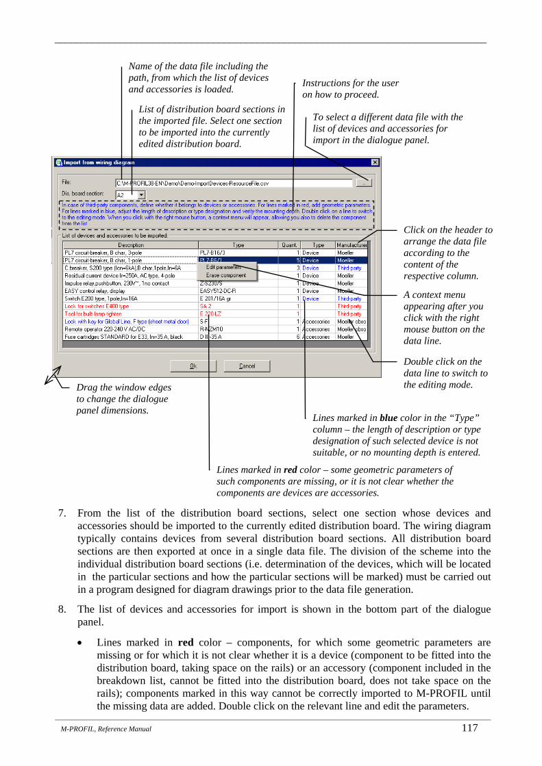
_______________________________________________________________________________
_______________________________________________________________________________________________________________________
M-PROFIL, Reference Manual 117
7. From the list of the distribution board sections, select one section whose devices and
accessories should be imported to the currently edited distribution board. The wiring diagram typically contains devices from several distribution board sections. All distribution board sections are then exported at once in a single data file. The division of the scheme into the individual distribution board sections (i.e. determination of the devices, which will be located in the particular sections and how the particular sections will be marked) must be carried out in a program designed for diagram drawings prior to the data file generation.
8. The list of devices and accessories for import is shown in the bottom part of the dialogue panel.
• Lines marked in red color – components, for which some geometric parameters are missing or for which it is not clear whether it is a device (component to be fitted into the distribution board, taking space on the rails) or an accessory (component included in the breakdown list, cannot be fitted into the distribution board, does not take space on the rails); components marked in this way cannot be correctly imported to M-PROFIL until the missing data are added. Double click on the relevant line and edit the parameters.
Name of the data file including the path, from which the list of devices and accessories is loaded.
To select a different data file with the list of devices and accessories for import in the dialogue panel.
Instructions for the user on how to proceed.
List of distribution board sections in the imported file. Select one section to be imported into the currently edited distribution board.
Click on the header to arrange the data file according to the content of the respective column.
A context menu appearing after you click with the right mouse button on the data line.
Drag the window edges to change the dialogue panel dimensions.
Double click on the data line to switch to the editing mode.
Lines marked in red color – some geometric parameters of such components are missing, or it is not clear whether the components are devices are accessories.
Lines marked in blue color in the “Type” column – the length of description or type designation of such selected device is not suitable, or no mounting depth is entered.

_______________________________________________________________________________
_______________________________________________________________________________________________________________________
118 M-PROFIL, Reference manual
• Lines marked in blue color in the “Type” and “Manufacturer” columns - the length of description or type designation of such selected device is not suitable, or no mounting depth is entered. Double click on the relevant line and edit the parameters.
• Lines marked in black color – Moeller components from the database or third-party components, for which all required data are defined. Double click on the relevant line to view the component parameters.
• Click on the column header to arrange the data table according to the selected column. Example: click on the header of the “Manufacturer” column to arrange the “Third-party devices” (i.e. devices from other manufacturers than Moeller) at the beginning of the data table; the table will be more transparent and readable since the parameters of third-party devices usually need to be edited.
• Click with the right mouse button on the data line to show the context menu. It allows you to switch to the component editing mode or to erase the component from the list.
9. Double click on every line marked in red or blue color and complete the missing data:
• A line was marked in red: the component type is not determined and all geometric parameters are not defined:
• A line was marked in blue: the mounting depth is identical to the maximum depth (this does not necessarily have to be an error; however, these values are usually different for modular devices such as circuit-breakers or residual current circuit-breakers; on contrary, these values are identical in case of contactors or frequency inverters. An incorrectly defined mounting depth will cause that the device cannot be fitted on the mounting rail
Component type: • Device – a component to be fitted into the distribution board, taking
place at the rails; all geometric data must be defined. • Accessories – a component included in the breakdown list, cannot be
fitted into the distribution board, does not take place on the rails, geometric data cannot be entered. Information concerning the
items to be completed in the dialogue panel. Definition of dimensions for a third-party device, click on the image to enlarge it.
Device description – text to be displayed in the breakdown list of components (type, basic technical parameters, manufacturer, ...), max. length 50 characters.
Type designation according to the manufacturer (max. 20 characters). It is used for device identification.
Device dimensions, for geometrical relevance see image at the right.
Power loss – used to check the temperature rise in the distribution board.

_______________________________________________________________________________
_______________________________________________________________________________________________________________________
M-PROFIL, Reference Manual 119
under the cover plate with cutout. The problem can also consist in the text length of the description or type designation exceeding the max. allowed value.
• A line was marked in black: Moeller components from the database – parameters cannot be edited:
10. If you want a certain component to be erased from the imported list (e.g. a distribution board
from another manufacturer, etc.), click with the right mouse button on the line that you want to erase and select the item “Erase component” in the context menu.
11. Click OK to close the dialogue panel. The components will be imported to the list of devices and accessories.
15.5.1 Structure of the file containing the list of devices and accessories ensuring the interconnection with the wiring diagram drawing software
The program M-PROFIL version 3.6 and higher allows you to create a list of selected devices to be fitted into the distribution board and accessories by loading a data file. Via this file, it is possible to create interconnection with any wiring diagram drawing program, which can export data to a file of the defined shape. The data file is currently generated by the diagram drawing program ElproCAD version 2.7.2 and higher from Astra92 a.s. Zlín, Czech Republic.
Information concerning the items to be completed in the dialogue panel.
These values must be verified as for whether they are really identical. Device description max. 50 characters.
Type designation max. 20 characters.

_______________________________________________________________________________
_______________________________________________________________________________________________________________________
120 M-PROFIL, Reference manual
File structure – general: • A text file in CSV standard (a file with variable field width, the individual fields are separated
by the semi-colon character (;), if there is a semi-colon inside the field text, the entire text is placed in double quotation marks (")).
• The first line in the file is the header, showing the code marking of the particular fields (columns).
• The sequence of the individual fields in the line is fixed.
File structure:
1st line: field names: Name; Type; Code; Price; Width; Height; Deep; Mounting; Tag; CaseNo; Pieces; Database; RecordNo
2nd and further lines: data
Field No
Field Name ElproCAD
Field Name M-PROFIL
Description
0 Name (Název)
Description (Popis)
Verbal description of the product together with its main technical parameters (e.g.: Residual current relay, select, Ir=5kA, sensitive to pulse DC current) – if there is a semi-colon character (;) inside the text, the entire text is placed in quotation marks (") (e.g. "Residual current relay; Ir=5kA"). This does not have to be indicated for Moeller products (will be searched in the M-PROFIL database).
1 Type (Typ)
Type (Typoz)
Type designation of the product (e.g.: PFR2-03-S/A). This does not have to be indicated for Moeller products (will be searched in the M-PROFIL database).
2 Code (Výrobek)
Code (Objc)
Ordering number of the product (e.g.: 000235864, zeroes in the front do not have to be indicated). This MUST be indicated for Moeller products (ensures the link to the M-PROFIL database).
3 Price (Cena)
Price (Cena)
Price for 1 piece of the product [CZK]. This does not have to be indicated for Moeller products (will be searched in the M-PROFIL database).
4 Width (Šířka)
Width (S)
Width in [mm]. This does not have to be indicated for Moeller products (will be searched in the M-PROFIL database).
5 Height (Výška)
Height (V)
Height in [mm]. This does not have to be indicated for Moeller products (will be searched in the M-PROFIL database).
6 Deep (Hloubka)
DeepMax (Hmax)
Maximum depth (“from rail to lever”) in [mm]. This does not have to be indicated for Moeller products (will be searched in the M-PROFIL database).
7 Mounting (Montáž)
Mounting (Montaz)
Method of mounting – key word: DIN = DIN rail, PLE = mounting plate PAN = panel, PRI = busbar system If the column is not indicated in the database, it remains empty. This does not have to be indicated for Moeller products (will be searched in the M-PROFIL database).
8 Tag (ProjOzn)
Tag (ProjOzn)
Design identification – product identification in the wiring diagram.
9 CaseNo (ČísloPole)
CaseNo (CisloPole)
Number of the distribution board section, in which the product is installed. At least one character must always be specified.

_______________________________________________________________________________
_______________________________________________________________________________________________________________________
M-PROFIL, Reference Manual 121
10 Pieces (PočKs)
Pieces (PocKs)
The quantity (pieces) of the product with identical project marking (1 pcs. as standard, more pieces in case 3 pcs. of an 1-phase device are connected in a 3-phase system). 1 or more must always be specified.
11 Database (Databáze)
Database (Databaze)
Database identification (e.g. EPC-1073). It can be replaced by the word MOELLER (component from the M-PROFIL database) and anything else for other manufacturers.
12 RecordNo (Věta)
RecordNo (Veta)
Number of the database record (an unambiguous product identifier within the source program database). This does not have to be filled in.
File example: Name; Type; Code; Price; Width; Height; Deep; Mounting; Tag; CaseNo; Pieces; Database; RecordNo Residual current relay, select,Ir=5kA,sensitive to pulse DC current; PFR2-03-S/A; 235864; 3650.00; 70.0; 90.0; 68.0; DIN; FI1; 1; 1; EPC-1073; 2439 Circuit-breaker, S200 series (Icn=6kA),char.B,2-pole,In=63A; S 202-B 63; 2CDS252001R0635; 465.00; 35.00; 85.00; 69.00; DIN; FA55; 1; 1; epc-1007; 12529 Switch lock E 400; SA 2; GJF1101903R0002; 198.00; ; ; ; ; ; 1; 1; epc-1007; 2232 Notes:
• The file can be created “manually” using Microsoft Excel. The file with the template ImportDevices-Template.xls, containing the above-specified columns in the required sequence, is located in the directory...\DEMO. Once the template is filled with the necessary data, this file must be saved in CSV format using the Excel function Save As. A demonstration example of the processed file for import Demo-ImportDevices-ResourceFile.csv can also be found in the directory ...\DEMO.
15.6 Working with the list of the selected devices The list of the selected devices can be viewed in two modes:
• Brief view - every device type has one line and the total quantity is indicated. Only a single line can be selected for editing; it is not possible to perform operations associated with the procedure of fitting devices on the distribution board rails and to edit tags.
Switch to detailed view.
The list of devices is not sorted; devices are listed in the same order as they were inserted.
View information about the selected device.
Search component by type or by order number (see Chap. 17).
Function to change the position of the selected component in the list (move it one line up or down).
Working with clipboard -
Copy, Paste

_______________________________________________________________________________
_______________________________________________________________________________________________________________________
122 M-PROFIL, Reference manual
• Detailed view – every individual piece of devices is shown together with its design identification and position on the distribution board rail (if the device is fitted). Unfitted devices are marked in red. The list of fitted devices is arranged according to the position on the distribution board frame rails (top-down, left-right, left frame first, right frame second). Unfitted devices are at the beginning of the list. The position of unfitted devices in the list can be adjusted. It is possible to perform all operations with the devices.
• Click on the icon Copy to clipboard to copy the selected devices to the program’s internal clipboard. Use the clipboard to transfer the devices into another distribution board in the project. The clipboard cannot be used to transfer devices to other applications.
• Click on the icon Paste from clipboard to paste the devices from the program’s internal clipboard to the list of selected devices. The clipboard cannot be used to transfer data from other applications.
• Click on the “Move device up in the list” icon to move the selected line up in the list by one line. It is only possible to move the lines in the brief view or the unfitted devices in the detailed view (a single line only must be selected in the detailed view mode, otherwise the icon is disabled).
• Click on the “Move device down in the list” icon to move the selected line down in the list by one line. It is only possible to move the lines in the brief view or the unfitted devices in the detailed view (a single line only must be selected in the detailed view mode, otherwise the icon is disabled).
• If you click on the “Information about device” icon, you can see completely all information about the device from the database, which makes the identification of the device to be edited easier for you (only one line must be selected in the detailed view mode, otherwise the icon is disabled).
• If you click on the “Print detailed list of devices” icon, you can print the detailed list of devices including the tags and positions of the devices in the distribution board.
Switch to brief view.
The list is sorted according to how the devices are fitted on the frame rails.
View information about the selected device.
Device, which is not fitted - in red color.
Fitted device – in black color.
Identification of the rail, on which the device is fitted (type, identification of the frame L - left, R - right, rail height on the frame), or the reason for the device not being fitted can be indicated.
Device tag.
Print the list of devices including tags and position in the distribution board.
Function to change the position of the selected unfitted component in the list (move it one line up or down).
Working with clipboard -
Copy, Paste

_______________________________________________________________________________
_______________________________________________________________________________________________________________________
M-PROFIL, Reference Manual 123
15.7 Editing tags
1. Roll down the project structure tree by clicking on the “+” sign next to the distribution board name. Double click on the “Devices” branch. A window with the list of the already inserted devices appears.
2. Switch to the detailed view of the list of the selected devices (see Chap. 15.6). 3. Select the device, the tag of which you want to change. It is also possible to select several
devices to be edited by dragging mouse over the list or to click on the first line, press Shift and click on the last line of the selection.
4. Click on the “Modify tag” icon (this function is accessible also in case the continuous tag specification when inserting the devices is disabled). A dialogue panel will open, in which you enter the new tag.
5. Click Add tags. The new entered tag will be recorded in the list and the dimensional drawing of the distribution board will be repainted.
6. Close the window with the list of the selected devices by clicking on the X in the right corner or by pressing Esc.
15.8 Changing the device quantity in the list of the selected devices
1. Roll down the project structure tree by clicking on the “+” sign next to the distribution board name. Double click on the “Devices” branch. A window with the list of the already inserted devices appears.
2. Click on the line containing the device, which you want to edit. Only a single line must be selected in case of the detailed view of the list of the selected devices.
3. Click on the “New quantity” icon. A dialogue panel will open, in which you enter the new quantity of the selected component.
This field is enabled only if the tag for several devices is being edited. The number will be increased progressively by the entered interval for the individual devices; the tag will thus be, for instance, FI1, FI2, ...
Edit the tag of the selected device.
The new specified tag will NOT be attached, the original values will remain unchanged.
The new tag will be attached to the component.

_______________________________________________________________________________
_______________________________________________________________________________________________________________________
124 M-PROFIL, Reference manual
4. If you activate this function from the brief view of the list of the selected devices: • If you increase the quantity, the new pieces will be inserted without tags (for tag editing
see Chap. 15.7). • If you reduce the quantity, some pieces will be erased regardless of their tags; therefore,
it is recommended to reduce the quantity by erasing the devices with detailed view of the list of the selected devices where you can specify the erased pieces precisely according to its tag (see Chap. 15.9).
5. If you activate this function from the detailed view of the list of the selected devices: • If you increase the quantity, you will be asked to enter the tag for the new pieces in a
similar manner as when inserting new devices in the list, see Chap. 15.1, item 6. The entry of tags can be overridden by means of the Options function (see Chap. 26.5).
• The quantity cannot be reduced.
6. Close the window with the list of the selected devices by clicking on the X in the right corner or by pressing Esc.
15.9 Erasing a device from the list of the selected devices
1. Roll down the project structure tree by clicking on the “+” sign next to the distribution board name. Double click on the “Devices” branch. A window with the list of the already inserted devices appears.
2. Click on the line containing the device, which you want to erase. In case of the detailed view of the list of the selected devices, it is also possible to select several components to be erased by dragging mouse over the list or to click on the first line, press Shift and click on the last line of the selection.
3. Click on the “Erase the selected device” icon. The selected devices will be erased from the dimensional drawing as well as from the list of the selected devices.
4. Close the window with the list of the selected devices by clicking on the X in the right corner or by pressing Esc.
15.10 Continuous test of the devices to be fitted on the distribution board rails When a component of device type (i.e. a device of Moeller brand, third-party device, connecting sleeve or terminal block) is inserted in the list of selected devices or when the quantity of a previously selected is changed, a continuous check is carried out as to whether the distribution board can accommodate the device, i.e. whether the sum of widths of all the selected devices is lower the sum of widths of all the mounting rails in the distribution board. If the test is passed successfully, nothing happens and the component being inserted is inserted in the list of the selected devices. In the opposite case, the following error message will appear:

_______________________________________________________________________________
_______________________________________________________________________________________________________________________
M-PROFIL, Reference Manual 125
The message only warns the user about the occurring situation. If you close the message panel by clicking OK, the component will be inserted in the list of the selected devices. It is left upon the user whether or not he/she reduces the quantity of components in the list of selected devices in some way. This test is carried out only for orientation purposes. A detailed calculation of how the devices can be fitted on the distribution board rails (taking into account the rail types, installation depth, device dimensions etc.) is carried out when the devices are actually fitted on the distribution board rails (see Chap. 15.11.1, 15.11.2). The execution of this test can be overridden by ticking the field “Do not show this warning again”. It is suitable to override the execution of this test for instance when it is necessary to create a set of components to be ordered from the wholesaler, but the individual components will not constitute one single distribution board.
15.11 Fitting devices on distribution board rails/door Whereas the continuous test of the devices to be fitted in the distribution board compares only whether the sum of widths of all the selected devices is lower than the sum of widths of all mounting rails in the distribution board, all mechanical relations are taken into account when the devices are fitted on the rail, such as: active rail width, rail type, mounting depth of the rail, maximum device depth etc. A detailed test of the design feasibility is carried out through the devices being fitted on the distribution boar rails completely. The command and signalling devices are fitted on the distribution board door.
15.11.1 AutoFit devices on distribution board rails/door Fitting the devices on rails represents a rather lengthy and monotonous work. In many cases, the accurate position of the individual devices on the frame rails does not matter in the first design. In such situation, it is thus possible to use the function for automatic fitting of the devices from the list of the selected devices on the frame rails / on door - the AutoFit function.
1. Click on the “AutoFit devices” icon in the M-PROFIL tool bar or on the “AutoFit devices” icon in the list of the selected devices.
2. If there are some devices already fitted on the rails, the following warning appears:
Space for devices on the distribution board rails (1 module = 17.5 mm).
Space occupied by the so-far selected components of device type (Moeller devices, third-party devices, connecting sleeves or terminal blocks).
The current reserve is negative. The number of components of device type must be reduced by this number of modules, or the space in the distribution board must be increased accordingly.
Override the execution of the continuous fitting test.

_______________________________________________________________________________
_______________________________________________________________________________________________________________________
126 M-PROFIL, Reference manual
3. The function will sort the devices from the list into logical groups and into groups depending on size so that the devices will be fitted from the distribution board top to its bottom in the following order: Other devices, Measuring devices, Switch clock, Contactors, Motor starters, Switch-disconnectors, Residual current devices, Surge voltage protectors, PL7 circuit-breakers, PLHT circuit-breakers, Core balance transformers, Fuse disconnectors, Power circuit-breakers. The devices are placed on the suitable rails step by step. The groups and their order are defined by the file ...\DATA\PRISTROJ\FGP_AUOS.DAT. The scope and order of the groups can be changed through modification of this file.
4. If there is at least one control or signaling device included in the list, which is mounted on the distribution board door, a dialogue panel will appear asking you to specify the grid of the devices on the door:
X
Y
Total number of devices to be fitted on door.
Position of the first device on door in the top left part: X – distance from the left door edge Y – distance from the bottom door edge
Number of devices under each other; determined automatically.
Number of columns – number of devices next to each other.
Exit the function, nothing is going to change; devices that are not fitted can be fitted manually one by one (see Chap 15.10.2).
Distance between device centers.
Information indicating that all devices from the list are fitted on the distribution board rails. The function is also used as a checking function – verification of complete fitting.
Distribution board door.
Exit the function, nothing is going to change (application recommended).
First device on door in the top left part.
Erase the fitted devices and blind flanges from the rails and fit them again.
Distance between columns.
Erase the fitted devices and blind flanges from the rails and fit them again (application recommended).
Distance between rows.
Information indicating that there are some devices in the list, which are not fitted.

_______________________________________________________________________________
_______________________________________________________________________________________________________________________
M-PROFIL, Reference Manual 127
• If you close the dialogue panel by clicking OK, the command and signalling devices will be fitted according to the specified grid. Devices, which the door cannot accommodate anymore, will not be fitted.
• If you close the dialogue panel by clicking Cancel, the command and signalling devices will not be fitted on the door.
• The relative position of the devices on the door and those on the rails is not checked; the possible collisions must be assessed and solved by the user from the dimensional drawing.
• The Door/Frame Switch view function allows you to set the image in a manner to show and print either only the door with the fitted devices or only the frame with the mounting rails and devices, or both (see Chap. 5.9).
5. The following information message appears when the process is completed:
• All devices from the list were fitted:
• Some devices in the list remain unfitted:
The list of the selected devices will appear subsequently in the detailed view and the pointer will be set to the first unfitted device. Unfitted devices are indicated in red and information about the reason for the device not being fitted is specified in the last column. You can either try to fit the remaining devices one by one (see Chap. 15.11.2) or close the list by pressing Esc and modify the distribution board design (select a larger distribution board, insert another rail of a suitable type, modify the rail depth etc.).
6. In case any blind flanges were fitted in the cutouts of the cover plates prior to launching the
AutoFit function, these blind flanges will be removed from the cutouts (but not from the list of the selected blind flanges). Subsequently it is necessary to fit the blind flanges again (see Chap. 13.1, 13.2).
7. Position of the devices on the distribution boar rails can be changed by means of the function “Move device from one rail to another” (see Chap. 15.11.4) and “Move the fitted device” (see Chap. 15.11.5).

_______________________________________________________________________________
_______________________________________________________________________________________________________________________
128 M-PROFIL, Reference manual
15.11.2 Fitting the selected device on distribution board rails/door This function allows you to fit one piece of device from the list of the selected devices on the distribution board rails.
1. Roll down the project structure tree by clicking on the “+” sign next to the distribution board name. Double click on the “Devices” branch. A window with the list of the already inserted devices appears.
2. Switch to the detailed view of the list of the selected devices (see Chap. 15.6). 3. Select one or more devices to be fitted on the rail (either by dragging over the list or clicking
on the first line, pressing Shift and clicking on the last selection line). None of the selected devices may be fitted – they must all be marked in red. All selected devices must be designed to be fitted on the frame rails or on the door.
4. Click on the icon “Fit the selected device to the distribution board”. 5. The window with the list of the selected devices will be closed. The pointer will change to a
cross-hair shape. • If one control or signaling device was selected to be mounted on the distribution board door,
click on the point where the center of the first device should be. The system checks whether the clicked point lies in the active door area and, if this is the case, the device will be inserted at the defined position. Note: in case the inserted device is not shown in the dimensional drawing, verify whether the distribution board door view is activated (see Chap. 5.11).
• If more control or signaling devices was selected to be mounted on the distribution board door, enter the horizontal distance between the individual devices and then click at the point where the center of the first device should be. In case the clicked point lies in the active door area, the first device will be inserted at the defined position and the other devices will be inserted to the right of the first one at the defined distance. In case the device would reach out of the active door area, it will not be inserted. Only one row of devices can be created in this manner.
• As for rail-mounted device or devices, click on the rail where the selected device (or the first device from the group) should be inserted, at the point where the left center of the device should be located. The system checks:
• whether a rail has been selected; • whether a rail was selected of the type suitable for the device to be inserted; data about the
mounting rail are integral part of the database information; • the compliance between the rail and the device is tested:
• If the mounting depth of the rail is smaller than the installation depth of the device, the device cannot be fitted - an information message appears; it would not be possible to cover the frame with cover plates.
• If the mounting depth of the rail >= the installation depth of the device and, at the same time, the mounting depth of the rail < the maximum depth of the device, then the device is fitted on the rail (naturally provided all the other checks are successfully passed). The device will be placed ideally in the cover plate cutout.
• If the mounting depth of the rail >= the installation depth of the device and, at the same time, the mounting depth of the rail > the maximum depth of the device, it means that the device will be “sunk” below the cover plate. In such case the user will be notified on this situation through an information message and he/she can decide whether or not the

_______________________________________________________________________________
_______________________________________________________________________________________________________________________
M-PROFIL, Reference Manual 129
device should be inserted on this rail. In this manner it is possible to fit, for instance, instrumentation or terminal blocks that are fully hidden under the cover plate without cutout.
• whether the device will be located in the active rail area (devices cannot be fitted along the full rail length, inactive edges defined by the rail shape and cover plates are located at both ends of the rail); if the device reached outside of the active rail area, the user will be offered with the possibility to insert it “at its own risk” (this is used when inserting fuse disconnectors or for subsequent modifications of cover plates through cutouts);
• whether there is not any collision with the already fitted devices; if this is the case, the system offers you the possibility to move the already fitted devices being in the way to the right. If you agree, the system checks whether the moved devices do not fall out from the rail and if not, the system will move them. In the opposite case, the function is terminated. In case everything is OK, the system offers you to move the device to the closest device on the left. If you agree, the device will be inserted right behind the closest device on the left from the pointed place. In the opposite case, it will be inserted in the pointed place.
• The procedure is repeated for all fitted devices. The next selected device will be fitted to the right from the previous one. One row only can be fitted in this manner.
• Devices are always fitted from the left edge of the rail to the right one. • The insertion point is always on the right side of the device, its position depends on the
position of the mounting slot. • Note: if the inserted device is not displayed in the dimensional drawing, please check whether
you have enabled the frame view of the distribution board (see Chap. 5.10).
6. When the insertion is completed, the list of selected devices is shown again. Unfitted devices are at the beginning of the list. The next unfitted device is selected automatically. Repeat steps 3-5 until you fit all devices.
7. Close the window with the list of the selected devices by clicking on the X in the right corner
or by pressing Esc.

_______________________________________________________________________________
_______________________________________________________________________________________________________________________
130 M-PROFIL, Reference manual
Notes: • Collision with blind flanges fitted in the cover plate cutouts is not tested. • The cover plate above the rail is not tested for the presence of a cutout. • The relative position of the devices on the door and those on the rails is not checked; the
possible collisions must be assessed and solved by the user from the dimensional drawing. • The list of fitted devices is arranged according to the position on the frame rails (top-down,
left-right, left frame first, right frame second, unfitted devices at the beginning of the list). The position of the device in the list changes once the device is fitted.
• Position of the devices on the distribution boar rails can be changed by means of the function “Move device from one rail to another” (see Chap. 15.11.4) and “Move the fitted device” (see Chap. 15.11.5).
• The tag of a device inserted on a rail can be modified by means of the “Modify tag” function (see Chap. 15.7).
• A device fitted on a rail can be erased by means of the “Erase the fitted device from the rail” function (see Chap. 15.11.3).
• If you want to erase a device from the list, including all its fitted positions being erased, you can do so by means of the “Erase the selected device” function (see Chap. 15.9).
15.11.3 Removing a fitted device from rail/door
1. Roll down the project structure tree by clicking on the “+” sign next to the distribution board name. Double click on the “Devices” branch. A window with the list of the already inserted devices appears.
2. Switch to the detailed view of the list of the selected devices (see Chap. 15.6). 3. Click on the line containing the device, which you want to remove. It is also possible to select
several components to be removed by dragging mouse over the list or to click on the first line, press Shift and click on the last line of the selection.
4. Click on the “Remove the fitted device” icon. The selected devices will be removed from the rails or door, but not from the list of the selected devices. Devices, which are not fitted, are indicated in red in the list. When the list is regenerated (e.g. after you have fitted some device), unfitted devices will be shown at the start of the list.
15.11.4 Moving fitted devices from one rail to another This function allows you to change the position of one or more devices fitted while simultaneously performing all checks for mechanical relations and collision with adjacent devices. The function can also be used to change the position of devices on the distribution-board door.
1. Click on the icon Move device from one rail to another in the M-PROFIL toolbar. 2. Select the device to be moved using one of the following methods:
• Click on any entity constituting the device scheme with the selection target. The selected device will be highlighted. The horizontally fitted devices are to be selected at the left-hand half.
• Click in a place where no device is located – thus activating the selection window. If you move your mouse to the left from the first clicked point, the cross-wise selection window is dragged (all devices lying inside the window will be selected as well as devices

_______________________________________________________________________________
_______________________________________________________________________________________________________________________
M-PROFIL, Reference Manual 131
interfering within the window). Click the opposite corner of the window. The selected devices will be highlighted.
• Click in a place where no device is located – thus activating the selection window. If you move your mouse to the right from the first clicked point, the window-type selection window is dragged (only devices lying fully inside the window will be selected). Click the opposite corner of the window. The selected devices will be highlighted.
• Tip: under the Options, it is possible to modify the control mode of the selection windows (either with click-click as in AutoCAD – default settings, or with click-hold as in Windows).
3. Close the selection of the devices by clicking on the right mouse button. 4. Click the new position of the selected group of devices. 5. If a device on door is concerned, click the new position for the center of the first selected
device. The relative position of the selected devices in the group will be retained. The system checks whether each of the moved devices is located in the active area of the door and, provided this is the case, it will be inserted into the new position.
6. If a device on rail is concerned, click the new position for the first selected device on the rail (the same one or a different one). Click on the rail where you want to insert the selected devices, into the point where the left center of the device will be located. (If you want to insert the device between two already existing devices that are placed very close to each other, select the rail inside the device which you want to move aside). For each moved device, the system checks the following: • Whether a rail was selected, • Whether a rail type was selected that is suitable for the moved device, • Whether the installation depth is suitable, • Whether the device will be located in the active area of the rail, • Whether there is any collision with the already fitted devices; if this is the case, the
system offers the possibility to move to the right the already fitted devices, which are in the way; if you agree with this operation, the system checks whether the device being moved aside do not fall out from the rail and if not, they will be moved; in the opposite case the function will be terminated and the device to be moved will remain in its original position.
7. Provided everything is OK, the system offers the possibility to bring the first device closer to the next device immediately on the left. If you agree, the device will be inserted immediately after the closest device on the left from the pointed place; in the opposite case it will be inserted directly in the place you pointed. The next selected devices will be inserted behind the first moved device in one line and in the same sequence as they have been selected.
8. Change the position of all required devices by repeated activation of this function.

_______________________________________________________________________________
_______________________________________________________________________________________________________________________
132 M-PROFIL, Reference manual
15.11.5 Moving fitted devices The function allows you to change the position of fitted devices freely without any limitation and without checking for collision with the adjacent components.
1. Click on the Move Devices icon at the toolbar of the M-PROFIL program.
2. Since the function performs no check for collisions between the moved device and the adjacent components, the following information message appears:
3. Select the device to be moved using one of the following methods:
• Click on any entity constituting the device scheme with the selection target. The selected device will be highlighted. The horizontally fitted devices are to be selected at the left-hand half.
• Click in a place where no device is located – thus activating the selection window. If you move your mouse to the left from the first clicked point, the cross-wise selection window is dragged (all devices lying inside the window will be selected as well as devices interfering within the window). Click the opposite corner of the window. The selected devices will be highlighted.
• Click in a place where no device is located – thus activating the selection window. If you move your mouse to the right from the first clicked point, the window-type selection window is dragged (only devices lying fully inside the window will be selected). Click the opposite corner of the window. The selected devices will be highlighted.
• Tip: under the Options, it is possible to modify the control mode of the selection windows (either with click-click as in AutoCAD – default settings, or with click-hold as in Windows).
4. Close the selection of the devices by clicking on the right mouse button. 5. Click the new position of the group of devices – click any point you wish anywhere in the
graphic area. The devices will be moved to the new position regardless of their collisions with the adjacent components (the relative position of the selected devices in the group will be retained).
Example: Utilization of the Move the Devices function for fitting the NZM circuit-breaker on the withdrawable-version socket in the xEnergy distribution box
1. Design the xEnergy series stand-alone distribution box, the incomer section with an NZM circuit-breaker of a withdrawable version, with external actuation (see Chap. 9.2) – insert both the device, the NZMH4-AE1600 (and +NZMH4-XAVE withdrawable carrier as accessory)
Override the pop-up of this information at the second and each following activation of the function.

_______________________________________________________________________________
_______________________________________________________________________________________________________________________
M-PROFIL, Reference Manual 133
circuit-breaker, and the +NZM4-XAV withdrawable-version socket into the list of the devices selected. The fitting of the motor drive will not be required.
2. Manually fit the distribution box with the withdrawable-version socket. 3. Manually fit the actual circuit-breaker, next to the withdrawable-version socket. Click the
insertion point immediately behind the right edge of the socket. Ignore the warning message saying ‘The insertion point goes beyond the active area of the rail’ (click Yes).
4. Move the device onto the socket by means of the Move the Devices function. Note: This procedure is necessary because the M-PROFIL system does not allow assemblies composed of several parts to be created interactively. This restraint will be eliminated in the next versions. An alternative to this procedure is to fit only the circuit-breaker, without fitting the socket.
Socket of the withdrawable versionThe circuit-breaker, fitted manually next to the socket
Insertion point for fitting the circuit-breaker manually; the message saying that the point goes beyond the active area of the rail is to be ignored (clicked Yes).
Moving the circuit-breaker above the socket by means of the Move the Devices function.
Final situation: the circuit-breaker is over
the socket.

_______________________________________________________________________________
_______________________________________________________________________________________________________________________
134 M-PROFIL, Reference Manual
16. Free Graphics _______________________________________________
The term of “free graphics” covers a group of functions allowing you to add basic graphical objects, such as a line, rectangle, circle and text, into the dimensional drawing of the distribution board. In this manner, it is possible to add notes or mounting instructions, for instance, or outline connections, sketch in busbars, add other command and signalling elements on doors etc. Free Graphics can be inserted in layers: either on the distribution-board frame (the level of the fitted devices) – in violet colour or on the distribution-board door – in dark-green colour. The line colour and type cannot be changed. The position and dimensions of objects can be modified. Functions enabling you to insert free graphics are located in the Draw drop-down menu. Functions enabling you to edit free graphics are located in the Modify drop-down menu. The drawing tools and utilities facilitating the insertion of free graphics can be found in the Tools drop-down menu. All functions associated with free graphics can be activated by clicking on icons in the Free Graphics toolbar.
16.1 Displaying the Free Graphics toolbar
1. Click on the icon Show/hide Free Graphics toolbar in the M-PROFIL tool bar. 2. The Free Graphics toolbar will appear.
• The position of the toolbar can be adjusted by dragging its top blue band. • It is possible to hide the toolbar again by clicking on the icon used to make it show, or by
clicking on the X in the top right corner of the toolbar.
16.2 Setting the layer for newly inserted free graphics
1. Click to show the Free Graphics toolbar (see Chap. 16.1). 2. Select the current layer for the newly inserted free graphics in the list of layers in the left part
of the toolbar (distribution-board frame or door).
16.3 Line
1. Click on the Line icon in the Free Graphics toolbar. 2. Click the initial point of the line (point B1). 3. Now drag the radius vector – a curve representing the future line. Click the
end point of the line (point B2).
Close the toolbar.
Drawing tools and utilities facilitating the insertion of free graphics (Grid, Snap, Ortho).
Current layer for the newly inserted free graphics (distribution-board frame or door).

_______________________________________________________________________________
_______________________________________________________________________________________________________________________
M-PROFIL, Reference Manual 135
4. The line is now inserted in the drawing. The layer, position and dimensions of the component can be modified at a later point in time (see Chap. 16.8-16.12). The insertion of components can be facilitated by tools and utilities of Grid, Snap and Ortho (see Chap. 16.7).
16.4 Rectangle
1. Click on the Rectangle icon in the Free Graphics toolbar. 2. Click one rectangle corner (point B1). 3. Now drag the shape representing the future rectangle. Click the opposite
corner of the rectangle (point B2). 4. The rectangle is now inserted into the drawing. The layer, position and dimensions of the
component can be modified at a later point in time (see Chap. 16.8-16.12). The insertion of components can be facilitated by tools and utilities of Grid, Snap and Ortho (see Chap. 16.7).
16.5 Circle
1. Click on the Circle icon in the Free Graphics toolbar. 2. Click the center of the circle (point B1). 3. Now drag the shape representing the future circle. Click the point defining the
circle radius (point B2). 4. The circle is now inserted into the drawing. The layer, position and dimensions of the
component can be modified at a later point in time (see Chap. 16.8-16.12). The insertion of components can be facilitated by tools and utilities of Grid, Snap and Ortho (see Chap. 16.7).
Note:
• When inserting a circle, the image of the adjacent graphics can be damaged (disappearance of the grid, irregular geometrical image). These image faults can be corrected by means of the Regenerate function from the View drop-down menu (see Chap. 23.1).
16.6 Text
1. Click on the Text icon in the Free Graphics toolbar. 2. Click the bottom left corner of the text (point B1). 3. A dialogue panel will open, in which you enter the text string and the font height:
4. The text is now inserted into the drawing. The default properties (colour) are determined by
the current layer, which can be modified at a later point in time, just like the text position, font height as well as the text itself (see Chap. 16.8, 16.9). The text font cannot be changed in this version.
Field to enter the text string. Only a single text line can be entered with one activation of the function.
Font height in points.

_______________________________________________________________________________
_______________________________________________________________________________________________________________________
136 M-PROFIL, Reference Manual
16.7 Drawing tools The following tools are applied when inserting free graphics:
• Grid – a network of dots filling the internal space of the distribution board and making the orientation easier. The grid display can be activated/disabled by means of the Grid function from the Tools drop-down menu, by means of the switch in the status bar or by pushing F7 key. The grid density (distance between the dots) can be set by means of the function called Drawing tools (see Chap. 16.7.1).
• Ortho – the movement of the pointer is locked in the direction of the coordinate axes. If this tool is activated, it is possible to draw lines, for instance, only in the horizontal or vertical direction. Otherwise it can be activated/disabled by means of the Ortho function from the Tools drop-down menu, by means of the switch in the status bar or by pushing F8 key.
• Snap – the clicked point is captured automatically to the vertexes of the invisible grid with a given spacing. The grid display can be activated/disabled by means of the Snap function from the Tools drop-down menu, by means of the switch in the status bar or by pushing F9 key. The grid density (distance between the dots) can be set by means of the function called Drawing tools (see Chap. 16.7.1). It is recommended to set the snap spacing identical with the distance of the grid dots.
• Coordinates – the current cursor coordinates are displayed at the status line (the centre of the coordinate system is the left-hand bottom interior corner of the stand-alone distribution box – see also Chap. 24.2). The indication can be turned on/off by means of the F6 key.
• Show print area margins: a dash and dot line will define the graphic area, the contents of which will be printed on paper (for more details see also Chap. 23.1). Any free graphics outside of the specified margins will not be printed.
• Cursor in the form of a crosshair: Normally, the cursor is in the form of an arrow (or, in the form of an arrow with a selection rectangle). For operations with the free graphics, the crosshair cursor may be more suitable (as in AutoCAD). The cursor form can be changed by means of the Program Settings function, the System tab (see Chap. 26.6).
16.7.1 Setting the Grid, Snap, turning on the indication of coordinates
1. Click on the Drawing Tools icon at the Free Graphics toolbar (or right-click on the drawing tools switch at the status line, or select the Drawing Tools item from the Tools drop-down menu).
Status line at the bottom part of the program window – information about the operation being performed.
Switches for the drawing tools make it easy to insert the free graphics. By clicking with the left button, the tool is turned on/off, by clicking with the right button, the ‘Drawing Tools’ function is activated.
The tool is turned on.
The tool is turned off.
Current coordinates of the cursor (the indication of these coordinates can be turned on/off by means of the F6 key).

_______________________________________________________________________________
_______________________________________________________________________________________________________________________
M-PROFIL, Reference Manual 137
2. Set the Grid and Snap spacing, possibly, turn on/off the individual tools (Grid, Snap, Ortho, Coordinates and Print area margins) in the dialogue panel that opens up subsequently. Afterwards, close the dialogue panel by clicking OK.
16.8 Editing the properties of the free graphics components The term of “editing the properties” means a change of all geometric (position, dimensions) and non-geometric (layer) properties of a component. The component to be edited can be selected in tow ways:
By means of the Properties icon: 1. Click on the Properties icon in the Free Graphics toolbar. 2. The pointer shape will change to the selection square. Now you are requested to select the
component to be edited (the request is shown in the status bar in the bottom part of the program main window, see Chap. 4.1).
3. Click on any line constituting the component, the properties of which you want to edit (so that the line lies within the selection square). A dialogue panel will appear allowing you to edit all properties of the selected component. The appearance of the dialogue panel depends on the type of the edited component.
By double clicking on the component: 1. Make sure that no command is active (the status bar in the bottom part of the program main
window is empty and the mouse pointer has the shape of an arrow). 2. Double click on any line constituting the component, the properties of which you want to edit.
A dialogue panel will appear allowing you to edit all properties of the selected component. The appearance of the dialogue panel depends on the type of the edited component.
• A line selected:
The coordinate system origin is located in the bottom left internal corner of the distribution-board box.
Set the component layer (distribution-board frame, or door). The layer determines the component default color (distribution-board frame = violet, distribution-board door = dark green; the color setting cannot be changed).
Modify the component geometry – it is possible to enter any coordinates of your choice. The coordinate system origin is located in the bottom left corner of the distribution board. The geometry modification can be carried out in a more comfortable way by means of Move (see Chap. 16.8) and Stretch (see Chap. 16.10) functions.
Definition of line colour and thickness regardless of the layer (change of default values for the edited object). The line type cannot be changed. These settings are not transferred to DXF!

_______________________________________________________________________________
_______________________________________________________________________________________________________________________
138 M-PROFIL, Reference Manual
• A rectangle selected:
• A circle selected:
• A text selected:
16.9 Changing the position of components
1. Click on the Move icon in the Free Graphics toolbar. 2. The pointer shape will change to the selection square. Now you are requested to select the
components to be moved (the request is shown in the status bar in the bottom part of the program main window, see Chap. 4.1).
3. Select all components you want to move. Either click on any line constituting the respective component (point B1), or use the selection windows:
• Click in any place where no component is located (point B2) – thus activating the
selection window.

_______________________________________________________________________________
_______________________________________________________________________________________________________________________
M-PROFIL, Reference Manual 139
• If you move your mouse to the left from the first clicked point, the cross-wise selection window is dragged (all components lying inside the window will be selected as well as components interfering within the window).
• If you move your mouse to the right from the first clicked point, the window-type selection window is dragged (only components lying fully inside the window will be selected).
• Click the opposite corner of the window (point B3). The selected components will be highlighted.
• Tip: under the Options, it is possible to modify the control mode of the selection windows (either with click-click as in AutoCAD – default settings, or with click-hold as in Windows).
• Note: only free graphics (lines, circles, …) and no devices, mounting rails or cover plates etc. can be moved with this function. When selecting components to be moved by means of the cross-wise window, only free graphics will be selected. For moving of devices fitted on the distribution-board frame or door - see Chap. 15.11.4, 15.11.5.
4. Exit the selection mode set by clicking on the right mouse button. 5. Click two points defining the shift vector - B4, B5 in the figure. The selected objects will be
moved to the new position. The determination of the new position can be facilitated by drawing tools and the Grid, Snap and Ortho tools (see Chap. 16.7).
16.10 Copying components
1. Click on the Copy icon in the Free Graphics toolbar. 2. The pointer shape will change to the selection square. Now you are requested to select
the components to be copied (the request is shown in the status bar in the bottom part of the program main window, see Chap. 4.1).
3. Select all components you want to copy (click on any line constituting the component) - points B1, B2, B3 in the figure. The selected component will be highlighted. It is also possible to use selection windows (for more details see the Move function in Chap. 16.9, item
After editing: Before editing:
B4B5
B1B3
B2
Objects to be moved (free graphics – circle on the distribution-board door) selected by means of the cross-wise window.
Shift vector.

_______________________________________________________________________________
_______________________________________________________________________________________________________________________
140 M-PROFIL, Reference Manual
3 of the instructions). This function can be used to copy free graphics only (lines, circles, ...), not to copy devices, mounting rails etc.
4. Exit the selection mode set by clicking on the right mouse button. 5. Click two points defining the shift vector - B4, B5 in the figure. The selected objects will be
copied to the new position. The determination of the new position can be facilitated by drawing tools and the Grid, Snap and Ortho tools (see Chap. 16.7).
6. Click another point defining the position of the next copy - points B6, B7. 7. Repeat step 5 until you make the desired number of copies. Exit the copying mode by clicking
on the right mouse button.
16.11 Changing the component geometry - Stretch
1. Click on the Stretch icon in the Free Graphics toolbar. 2. The pointer shape will change to the selection square. Now you are requested to select
the component to be stretched (the request is shown in the status bar in the bottom part of the program main window, see Chap. 4.1).
3. Select a component close to the point, which you want to stretch (end point of a line, corner of a rectangle etc.; this function can be used to modify free graphics only), point B1 in the figure. Now drag the radius vector from the selected definition point; you will be requested to define its new position.
4. Click the new position for the selected point - point B2. The object shape will be adjusted accordingly. The determination of the new position can be facilitated by drawing tools and the Grid, Snap and Ortho tools (see Chap. 16.7).
After editing: Before editing:
B4B5
B1B3
B2
B6
B7
Objects to be copied (free graphics – circle on the distribution-board door) selected by means of the cross-wise window.
Shift vector.

_______________________________________________________________________________
_______________________________________________________________________________________________________________________
M-PROFIL, Reference Manual 141
16.12 Erasing components
1. Click on the Erase icon in the Free Graphics toolbar. 2. The pointer shape will change to the selection square. Now you are requested to select the
component to be erased (the request is shown in the status bar in the bottom part of the program main window, see Chap. 4.1).
3. Select all components you want to erase (click on any line constituting the respective). The selected component will be highlighted (for more details see the Move function in Chap. 16.9, item 3 of the instructions).
4. Exit the selection mode set by clicking on the right mouse button. The selected components will be erased.
After editing: Before editing:
B1B2
Object selected to be copied (free graphics – circle on the distribution-board door).

_______________________________________________________________________________
_______________________________________________________________________________________________________________________
142 M-PROFIL, Reference Manual
17. Accessories _______________________________________________
A distribution board project includes a wide range of materials, which do not have any graphical representation in the front view of the distribution board and which are, however, essential for the complete mounting and must appear in the breakdown list of components. This concerns e.g. grips, screws, nuts, brackets, connections, flanges, labelling plates, locks, keys, … etc. Similarly, devices from the database must be accompanied with a wide range of components, which are not mounted to the distribution board rails (thus not having any graphical representation in the front view of the distribution board) and which are, however, essential for the complete mounting and must appear in the breakdown list of devices. These include e.g. labels, position locks for device levers, releases, adapters etc. Insertion of components for the RMQ command and signalling devices and XCOMFORT components without a fixed link to the distribution board provides maximum variability when preparing specifications, price offers etc. Most XCOMFORT components are available precisely as accessories. There is also the possibility to insert third-party accessories, i.e. accessories from a manufacturer other than Moeller. Step by step, the user creates a database of third-party accessories, which is independent of the currently edited distribution board, and can insert components from this database. Intangible “price” items can also be defined as third-party accessories; they will appear only in the breakdown list (such as extra charge for distribution board mounting etc.). Working with the accessories databases is very similar to working with the database of Moeller devices (see Chap. 15.1) and the database of third-party equipment (see Chap. 15.2). Similarly to the devices, the user selects items from the database and inserts them in the list of selected accessories for the currently designed distribution board.
17.1 Database of Moeller accessories
1. Roll down the project structure tree by clicking on the “+” sign next to the distribution board name. Double click on the “Accessories” branch (this branch is always present in the tree). A window with the list of the already inserted accessories appears.
2. Click on the icon “Database of Moeller accessories”. 3. A dialogue panel appears allowing you to work with the database Moeller accessories.
Select the required category of accessories in the database tree structure. Searching in the tree is identical to that in the tree of directories in the Windows Explorer. The same principles apply here as those governing the selection of devices from the database of devices (see Chap. 15.1). For instance, you want to insert 5 pieces of blank (unmarked) labels for device labelling in the list: • Double click on the “Accessories for Profi Plus distribution boards” branch - the tree covered
within this branch will roll down. • Click once on the branch “General (labels, ...)”. Since this is an end-branch of the database
tree, a data table with specific types appears. • Click on the line “Labelling strips”.

_______________________________________________________________________________
_______________________________________________________________________________________________________________________
M-PROFIL, Reference Manual 143
• Click on the Details button to view all information available about the selected accessories in the database:
• Click on the Price button to find out the current price of the selected accessories from the price list.
Select the accessories type from the tree of options. Tree operation: double click on a branch = roll down/up click one on a branch = select the branch
Data table of the specific types of accessories in the given branch.
Selected component; actions of other buttons relate to this component.
Price of the selected component.
Display all data from the database about the selected component.
Insert the entered quantity of the selected accessories in the list of the selected accessories to this distribution board.
End your work with the accessories database.
Quantity of the selected accessories, which will be inserted in the list of the selected
accessories to this distribution board.
Information about the performed insertion of the component in the list.
Settings of discounts and surcharges for different product groups see Chap. 21.5.
Drag the dialogue panel edges to change its size.
Search component by type or by order number (see Chap. 18).

_______________________________________________________________________________
_______________________________________________________________________________________________________________________
144 M-PROFIL, Reference Manual
4. Set the Quantity item to the value corresponding to the number of pieces of the selected accessories, which you want to insert in the list of selected accessories for this distribution board (i.e. 5 pieces in our case).
5. Click on the button “Insert in List”. The specified quantity of the selected accessories will be inserted in the list of selected accessories for this distribution board.
6. Repeat steps 2 - 4 until you insert all required accessories in the list. Move the window to view continuously updated information about the contents of the list of selected accessories.
7. Click Close to exit your work with the database of Moeller accessories. Note: Some components (such as BEL fastening elements, TIW depth straps etc.) are assigned to the distribution board automatically where required. These components are available in the accessories, however, they are selected only to create a reserve !!! (Thus, they will be provided as additional spare pieces.) Tip for designers: If you are familiar with the offered accessories of Moeller and it is quicker and more comfortable for you to search the accessories based on the type designation (rather than based on its properties), use the Search Component function (see Chap. 18).
17.2 Database of third-party accessories Accessories, which are not found in the database (primarily accessories from other manufacturers), are called Third-party accessories. All data, which are otherwise included in the database (description, type, price …) must be specified by the user for these components. Thereafter it is possible to insert the components in the list of selected accessories. Such component behaves the same way as Moeller accessories in the list of accessories with the only difference that it does not have any order number and its price is entered directly by the user (it is not taken over from the pricelist). Step by step, the user creates a database of third-party accessories, which remains the same regardless of the currently edited distribution board. Intangible “price” items can also be defined as third-party accessories; they will appear only in the breakdown list (such as extra charge for distribution board mounting etc.).
1. Roll down the project structure tree by clicking on the “+” sign next to the distribution board name. Double click on the “Accessories” branch (this branch is always present in the tree). A window with the list of the already inserted accessories appears.
2. Click on the icon “Database of third-party accessories”. 3. A dialogue panel appears allowing you to work with the database of third-party
accessories. Working with the database of third-party accessories is very similar to working with the database of third-party devices (see Chap. 15.2)
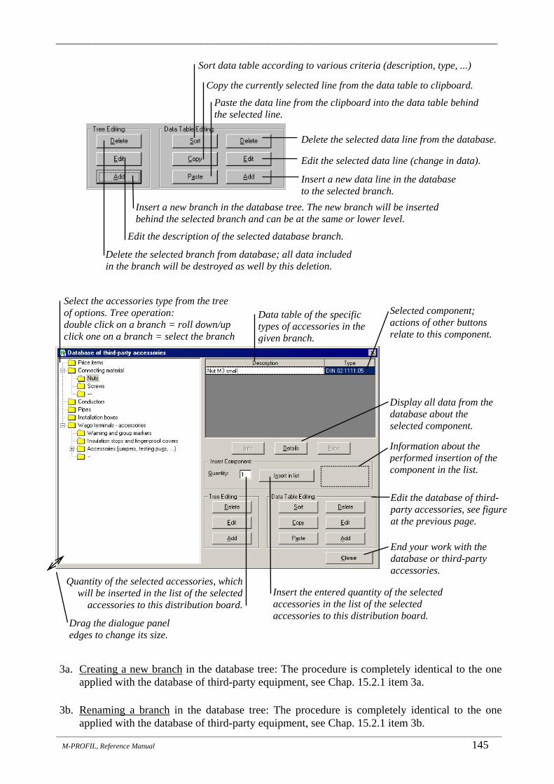
_______________________________________________________________________________
_______________________________________________________________________________________________________________________
M-PROFIL, Reference Manual 145
3a. Creating a new branch in the database tree: The procedure is completely identical to the one applied with the database of third-party equipment, see Chap. 15.2.1 item 3a.
3b. Renaming a branch in the database tree: The procedure is completely identical to the one
applied with the database of third-party equipment, see Chap. 15.2.1 item 3b.
Copy the currently selected line from the data table to clipboard.
Sort data table according to various criteria (description, type, ...)
Paste the data line from the clipboard into the data table behind the selected line.
Delete the selected data line from the database.
Select the accessories type from the tree of options. Tree operation: double click on a branch = roll down/up click one on a branch = select the branch
Edit the selected data line (change in data).
Data table of the specific types of accessories in the given branch.
Insert a new data line in the database to the selected branch.
Delete the selected branch from database; all data included in the branch will be destroyed as well by this deletion.
Selected component; actions of other buttons relate to this component.
Insert a new branch in the database tree. The new branch will be inserted behind the selected branch and can be at the same or lower level.
Display all data from the database about the selected component.
Edit the description of the selected database branch.
Insert the entered quantity of the selected accessories in the list of the selected accessories to this distribution board.
End your work with the database or third-party accessories.
Quantity of the selected accessories, which will be inserted in the list of the selected
accessories to this distribution board.
Edit the database of third-party accessories, see figure at the previous page.
Information about the performed insertion of the component in the list.
Drag the dialogue panel edges to change its size.

_______________________________________________________________________________
_______________________________________________________________________________________________________________________
146 M-PROFIL, Reference Manual
3c. Deleting a branch in the database tree: The procedure is completely identical to the one applied with the database of third-party equipment, see Chap. 15.2.1 item 3c.
4a. Inserting new accessories in the database to a given branch:
a) Select the branch in the database tree, to which you want to insert the desired component. In case this branch does not exist, you need to create it by following the instructions provided under 3a. It is advisable for this branch to be the end branch of the tree, but it is not a must.
b) Click on the Add button in the Data Table Editing group. A dialogue panel will open, in which you enter all required data defining the component:
c) Close the dialogue panel by clicking OK. The new component will be added to the end of
the data table.
4b. Inserting a new component in the database to a given branch by copying an existing component: The procedure is completely identical to the one applied with the database of third-party equipment, see Chap. 15.2.1 item 4b.
4c. Editing data of existing accessories in the database:
a) Select the branch in the database tree where the component is located, which you want to edit. b) Select the component to be edited in the data table. c) Click on the Edit button in the Data Table Editing group. The same dialogue will appear
as the one opening when defining a new component (see procedure under item 4a), with the current data about the edited component being pre-filled in the particular fields. These fields can be edited in any desired way. Edit the data. Close the dialogue panel by clicking OK. The data will be recorded in the database. CAUTION: the data concerned will be changed in the database, however, the data in the already inserted pieces used in distribution board will not be edited !
4d. Deleting accessories from the database:
a) Select the branch in the database tree where the component is located, which you want to delete. b) Select the component in the data table, which you want to delete. c) Click on the Delete button in the Data Table Editing group. The system will ask you
whether you are sure you want to delete the selected component from the database. If you
Device description - text, which will appear in the breakdown list of components (type, basic parameters, manufacturer, ...), max. 50 characters.
Type according to the manufacturer (max. 20 characters). It is used for identification of the device and for the duplicity test. It must be unique within the entire database!!
Catalogue price for one piece of the component (to calculate the total project price). The price specified here will not be adjusted any further.

_______________________________________________________________________________
_______________________________________________________________________________________________________________________
M-PROFIL, Reference Manual 147
confirm the deletion, the component will be deleted from the database (CAUTION - it will not be deleted from the list of accessories selected for this distribution board !!)
4e. Sorting the currently displayed database table. The procedure is completely identical to the
one applied with the database of third-party equipment, see Chap. 15.2.1 item 4e. 4f. Inserting third-party accessories from the database in the list of selected accessories for this
distribution board.
a) Select the branch in the database tree where the component is located, which you want to insert. b) Select the component in the data table, which you want to insert. c) Set the Quantity item to the value corresponding to the number of pieces of the selected
accessories, which you want to insert in the list of selected accessories for this distribution board.
d) Click on the button “Insert in List”. The specified quantity of the selected accessories will be inserted in the list of selected accessories for this distribution board. Move the window to view continuously updated information about the contents of the list of selected accessories.
5. Click Close to exit your work with the database of third-party accessories. 6. Close the window with the list of selected accessories by clicking on the X in the upper right
corner of the window or by pressing Esc. Note: Data files of the user-defined database of third-party accessories are located in the \DATA\VLASTNI\CIPRISL directory. We strongly recommend you to make a backup of this directory as not to lose the definitions in case of any system failure. For backup of the entire M-PROFIL system installation see Chap. 2.3.
Note: The list of devices can also be filled by loading a data file created by a diagram drawing program, which saves you the need to search the items from the database. For more details see Chap. 15.5.
Insert Moeller accessories.
Erase the selected component.
Change quantity of the selected component.
Insert third-party accessories. Search component by type or by order number (see Chap. 18).

_______________________________________________________________________________
_______________________________________________________________________________________________________________________
148 M-PROFIL, Reference Manual
17.3 Changing the accessories quantity in the list
1. Roll down the project structure tree by clicking on the “+” sign next to the distribution board name. Double click on the “Accessories” branch. A window with the list of the already inserted accessories appears.
2. Click on the line containing the component, which you want to edit. 3. Click on the icon “New quantity of …”. A dialogue panel will open, in which you enter the
new quantity of the selected component. Close the dialogue panel by clicking OK.
17.4 Erasing accessories from the list
1. Roll down the project structure tree by clicking on the “+” sign next to the distribution board name. Double click on the “Accessories” branch. A window with the list of the already inserted accessories appears.
2. Click on the line containing the component, which you want to erase. 3. Click on the icon “Erase selected component”. The component will be erased from
the list. Tip: If you click with your right mouse button in the list of the selected accessories, a context menu will appear allowing you to make a quick function selection (insert, new quantity, erase) and to apply it to the selected line.

_______________________________________________________________________________
_______________________________________________________________________________________________________________________
M-PROFIL, Reference manual 149
18. Searching Components in Data Structures _______________________________________________
For experienced users who mastered the system of creating type designations for the individual Moeller components, it is faster and more comfortable to search the component directly in the data structures based on its type designation or its order number rather than to search it step by step based on its properties (i.e. in the manner described in the previous chapters). The Search Component function allows quick search for the component in the M-PROFIL system data structures based on the order number (must be specified precisely) or based on the type designation (only a partial string can be entered and the system finds all suitable components). Complete information will be shown, which is available about the respective component found, and this component can be inserted in the list of selected components. There are three categories of components from the point of view of inserting a component in the list:
• Mechanical component for distribution board (compact distribution boxes, stand-alone distribution boxes, build. modules, rails, …) - the component cannot be inserted in the list of the selected components in this manner since the system does not know where to place the component’s geometric representation. These components can be inserted only by means of special functions.
• Device from the database of Moeller devices - the specified quantity of the component can be inserted in the list of selected devices.
• Moeller accessories - the specified quantity of the component can be inserted in the list of selected accessories.
A) Search by the type designation
1. Select the Search Component item from the Tools drop-down menu or click on the corresponding icon in the tool bar, or use the Ctrl+F shortcut.
Definition of the criterion to be used for component search.
The search string (part of the type designation or precise order number).
List of components containing the search string. Basic information about the selected component.
Insert the entered quantity in the respective list (depending on the component type).
Quantity of components, which should be inserted in the respective list.
Information about the performed insertion of the component in the list. Close dialogue panel.
Display additional information on the device (dimensions, diagram, ...).

_______________________________________________________________________________
_______________________________________________________________________________________________________________________
150 M-PROFIL, Reference Manual
2. Set the “Search according to” switch to the Type value. 3. Enter the type designation of the component you want to search into the String field. The
type designation does not have to be entered precisely; it is sufficient to specify only a partial string and the system will search all components, the type designation of which includes the required string. If you enter PL7 for instance, the system will find all PL7 circuit-breakers. Should the searched string contain the "?" character - question mark, any other arbitrary character can stand at the position of this character. E.g. if you enter PL7-63/3/? - the system will find all 3-pole circuit breakers of the L7 series, In=63 A regardless of their characteristic (i.e. PL7-63/3/B, PL7-63/3/C). When you complete the entry of the string, press Enter.
4. The list of Components found includes the set of type designations for all components that meet the specified string. Select one of them. Detailed information about the component will be shown in the bottom part of the dialogue window. If no component includes the specified string, an error message will appear and the list of Components found will be empty. If you click on the More information button, you can obtain more detailed data about the component (dimensions, wiring diagram etc.).
5. Set the required quantity of the component, which you want to enter in the list. Click on the button “Insert in List”. The entered number of pieces of the component will be inserted in the appropriate list depending on the component type (list of the selected devices - you will be required to enter the tag in this case, or the list of accessories). The message below the button informs you about the performed insertion. Mechanical components of the distribution board cannot be inserted in this manner, it is necessary to use special functions. The button “Insert in List” is disabled in this case.
6. Repeat steps 3 - 5 for all the components you are looking for. 7. Click Close to close the dialogue panel.
B) Search by the order number
1. Select the Search Component item from the Tools drop-down menu or click on the corresponding icon in the tool bar, or use the Ctrl+F shortcut.
2. Set the “Search according to” switch to the Order number value. 3. Enter the order number of the component you want to search into the String field. The precise
number must be entered. When you complete the entry of the string, press Enter. 4. Detailed information about the component will be shown in the bottom part of the dialogue
window. If no component includes the specified order number, an error message will appear and no information will be shown.
5. The possibility of a direct entry of the component quantity you require to be added in the respective list is available for devices and accessories similarly to the previous case.
6. Repeat steps 3 - 5 for all the components you are looking for. 7. Click Close to close the dialogue panel.
Notes: • If you insert the same component in the list repeatedly, you only increase the quantity
(number of pieces) of the given component. • For search of the devices based on their properties and for other operations with the list of the
selected devices see Chap. 15. • For search of accessories based on their properties and for other operations with the list of the
selected accessories see Chap. 17. • The search function does not cover the user-defined databases (third-party devices, terminal
blocks, third-party accessories).

_______________________________________________________________________________
_______________________________________________________________________________________________________________________
M-PROFIL, Reference manual 151
19. Checking Temperature Rise in Distribution Boards _______________________________________________
A separate module designed for calculation of temperature rise in distribution boards allows you to check whether the heat losses of fitted devices and conductors do not exceed the maximum value determined by the manufacturer for the selected distribution board type, and to determine the temperature rise and the temperature in the distribution board in accordance with the standard IEC 890+A1. The design of the distribution board must be performed in full prior to the calculation, as follows:
• Select all devices from the database to be fitted in the distribution board (see Chap. 15); • Design a suitable distribution board including its internal arrangement (see Chap. 6, 7, 8 a 9); • Check the fit of the devices in order to verify whether all the selected devices can be inserted
into the chosen distribution board (see Chap. 15.11) – however, the devices do not necessarily have to be fitted on rails in the distribution board.
The calculation itself is activated through the Temperature Rise function from the Distribution Board drop-down menu, or by clicking on the respective icon. The calculation procedure differs depending on the selected distribution board system:
• In case of Global-Line and Xboard compact distribution boxes, it is only checked whether the heat losses of the fitted devices do not exceed the maximum value determined by the manufacturer;
• In case of Profi Plus distribution boards, XVTL and xEnergy stand-alone distribution boxes, the temperature rise calculation is carried out in accordance with the standard IEC 890+A1.
19.1 Checking the temperature rise in compact distribution boxes
1. Make a full design of the Global-Line or Xboard compact distribution box (see Chap. 6, 15). 2. Activate the calculation through the Temperature Rise function in the Distribution
Board drop-down menu, or by clicking on the respective icon. 3. The following dialogue panel appears:
Maximum allowed heat power loss of devices in the compact distribution box as determined by the manufacturer.
Space for any comments from the manufacturer concerning the value of the maximum allowed power loss in the compact distribution box.

_______________________________________________________________________________
_______________________________________________________________________________________________________________________
152 M-PROFIL, Reference Manual
4. Click on the Settings >> button to view the list of selected devices and their power losses.
The list includes all selected devices (they do not necessarily have to be fitted on rails in the compact distribution box):
Total power loss of the selected devices in the list (they do not necessarily have to be fitted on rails of the compact distribution box).
View the list of selected devices and their power losses. Possibility to add the power loss where the value is missing. Current coincidence factor. Coincident power loss is equal to the square of the defined factor. Total coincident power loss of the selected devices in the list, adjusted with regard to the coincidence factor. Space for any comments concerning the power loss of the selected devices (e.g. warning that the power loss value is missing for some of the selected devices).
Check result: COMPLIANT – NON-COMPLIANT – CANNOT BE ASSESSED (cannot be assessed when the power loss value is missing for some of the selected devices).
Device, for which no power loss was entered (e.g. a third-party device or Moeller device where the power loss value was not supplied by the manufacturer). The values can be edited (red numbers). The power loss value must be defined for every device in order to be able to assess the temperature rise (the minimum value is 0.01). The user is responsible for the correctness of the entered value and, thus, also for the correctness of the calculations results.
• For Moeller devices, the entered value will be recorded in the database and will be automatically used as a default value for the next use of the same device.
• For third-party devices, we recommend entering the power loss in the database of third-party devices already prior to inserting the device to the distribution board (see Chap. 15.2).

_______________________________________________________________________________
_______________________________________________________________________________________________________________________
M-PROFIL, Reference manual 153
5. Add the power loss value, if it is missing for any of the fitted devices, and click OK to close
the list of selected devices and their power losses. 6. Set the current coincidence factor according to the actual situation. This is the current
coincidence; the coincident power lose is equal to the square of the defined factor. 7. The result of the check is continuously shown in the bottom part of the dialogue. The result of
the check serves only as information for the user, the report cannot be printed in this case.
19.2 Checking the temperature rise in distribution boards 1. Make a full design of the Profi Plus distribution board (see Chap. 7, 8; 10-14 and 15) or of the
XVTL or xEnergy stand-alone distribution box (see Chap. 9, 10-14 and 15). 2. Activate the calculation through the Temperature Rise function in the Distribution
Board drop-down menu, or by clicking on the respective icon. 3. A dialogue panel appears allowing you to enter additional parameters necessary to calculate
the temperature rise in accordance with IEC 890+A1:
• In general: grey numbers are taken over from the distribution board design (e.g. dimensions), or are determined through calculation of other values (e.g. power loss of busbars) – they cannot be directly edited, it is necessary to modify the distribution board design; black numbers are set at the default value and can be edited as desired.
Power loss of Moeller devices from the database. The values cannot be edited (grey numbers).
Drag the edges to change the size of the dialogue panel.
User-defined power loss. The values can be edited (black numbers).
Click on the item with black or red number and enter the new value.

_______________________________________________________________________________
_______________________________________________________________________________________________________________________
154 M-PROFIL, Reference Manual
• Dimensions – are determined through the selected distribution board, cannot be directly
edited. • Ambient temperature – a user-defined value to be used to calculate the temperature
inside the distribution board. • Area of ventilation holes – the area of suction holes for the cooling air inlet (holes in the
bottom part of the distribution board). The outlet holes located in the top part must have a greater or at least identical area. Cooling with naturally flowing air is envisaged (auxiliary fans are not taken into account). The default value is set based on the selected distribution board system and can be changed by the user, thus simulating the effect of additional ventilation holes, for instance.
• Number of horizontal partitions – the number of horizontal partitions hindering the air flow inside the distribution board. Those include e.g. partitions ensuring the internal division of the individual areas, or an electric meter trough or an IZM power circuit-breaker blocking nearly the entire distribution board depth, as the case may be. The default value is set based on the selected distribution board type and can be changed by the user.
• Method of installation – position of the distribution board section in the switchgear. The default value is set based on the position of the distribution board (surface-mounted, flush-mounted) and its position in the project structure tree (first section, internal section, or end section in the row). By clicking on the image, it is possible to select a different, more suitable position. The position description is shown below the images:

_______________________________________________________________________________
_______________________________________________________________________________________________________________________
M-PROFIL, Reference manual 155
• Power loss of main busbars – a simple calculator allows you to define the heat losses of the primary busbars (3 phases are considered automatically; it is presumed that the current in the N and PE conductors is negligible as regards temperature rise): • For xEnergy series distribution boards, the particular parameters (cross-section of
busbars, length) are set automatically according to the distribution board design. Only the current load can be edited; in case of end section, for instance, it can be significantly lower than the rated current of busbars. As regards primary busbars at the top, these busbars do not contribute to the total temperature rise since the heat is drawn off directly through the ceiling ventilation out of the distribution board.
• For other distribution boards, only the busbar length is predefined in accordance with the width of the distribution board, and it can also be edited. Other values, such as the cross-section and the current load, must be set according to the real situation.
• Power loss of dropper busbars – a simple calculator allows you to determine the heat losses of secondary busbars (3 phases are considered automatically; it is presumed that the current in the N and PE conductors is negligible as regards temperature rise):
Selected position (method of installation) of the distribution board.
Distribution board covered at all sides, cooling through the door only (e.g. flush-mounting or internal section in a very low switchgear).
Distribution board covered at all sides, cooling through the door and ceiling (e.g. internal section in the switchgear, a row of distribution boards close to the wall).
Distribution board covered at the side, cooling through the door, rear wall and ceiling (e.g. internal section in a row of distribution boards).
Distribution board covered at the side and in the back, cooling through the door, side wall and ceiling (e.g. a separate distribution board in the corner of the room).
Distribution board covered at the side, cooling through the door, side wall, rear wall and ceiling (e.g. end section in a row of distribution boards).
Distribution board covered in the rear, cooling through the door, side wall and ceiling (e.g. a stand-alone distribution board close to the wall).
Distribution board cooled from all sides (e.g. a stand-alone distribution board at a sufficient distance from the wall and other objects).
Verbal description of position (method of installation).
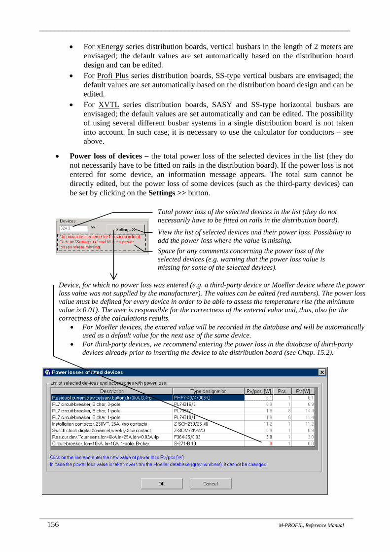
_______________________________________________________________________________
_______________________________________________________________________________________________________________________
156 M-PROFIL, Reference Manual
• For xEnergy series distribution boards, vertical busbars in the length of 2 meters are envisaged; the default values are set automatically based on the distribution board design and can be edited.
• For Profi Plus series distribution boards, SS-type vertical busbars are envisaged; the default values are set automatically based on the distribution board design and can be edited.
• For XVTL series distribution boards, SASY and SS-type horizontal busbars are envisaged; the default values are set automatically and can be edited. The possibility of using several different busbar systems in a single distribution board is not taken into account. In such case, it is necessary to use the calculator for conductors – see above.
• Power loss of devices – the total power loss of the selected devices in the list (they do not necessarily have to be fitted on rails in the distribution board). If the power loss is not entered for some device, an information message appears. The total sum cannot be directly edited, but the power loss of some devices (such as the third-party devices) can be set by clicking on the Settings >> button.
Total power loss of the selected devices in the list (they do not necessarily have to be fitted on rails in the distribution board).
View the list of selected devices and their power loss. Possibility to add the power loss where the value is missing. Space for any comments concerning the power loss of the selected devices (e.g. warning that the power loss value is missing for some of the selected devices).
Device, for which no power loss was entered (e.g. a third-party device or Moeller device where the power loss value was not supplied by the manufacturer). The values can be edited (red numbers). The power loss value must be defined for every device in order to be able to assess the temperature rise (the minimum value is 0.01). The user is responsible for the correctness of the entered value and, thus, also for the correctness of the calculations results.
• For Moeller devices, the entered value will be recorded in the database and will be automatically used as a default value for the next use of the same device.
• For third-party devices, we recommend entering the power loss in the database of third-party devices already prior to inserting the device to the distribution board (see Chap. 15.2).

_______________________________________________________________________________
_______________________________________________________________________________________________________________________
M-PROFIL, Reference manual 157
• Power loss of conductors – heat loss of conductors can be either estimated based on practical experience and entered as a specific value, or calculated by means of a calculator. The conductor cross-sections, lengths and current flows are entered in the calculator. The power loss is calculated automatically. In order to estimate the length of smaller cross-section conductors, you can take ca 0.5m of conductor per device pole. The current should be entered according to the rated current of the device to be connected. In case of various values of rated currents, use the maximum value. Attention should be paid particularly to conductors with larger cross-section and higher current load. The more precise values you enter, the more relevant the calculation result of the total temperature rise will be.
Power loss of Moeller devices from the database. The values cannot be edited (grey numbers). Power loss at rated current.
Drag the edges to change the size of the dialogue panel.
User-defined power loss. The values can be edited (black numbers).
Total power loss of conductors; it is possible to enter a specific value or to perform the calculation using the calculator.
Start up the calculator to calculate the power loss of conductors.
Click on the item with black or red number and enter the new value.
Cross-section of the conductor.
Total length of conductors of the respective cross-section (estimation hint: ca 0.5m per device pole).
Current in the conductors of the respective cross-section (rated current of the devices to be connected).
Power loss in conductors of the relevant cross-section.
Total power loss in conductors.
Click on the cell and enter the required value. Press Enter key to go to the next cell.

_______________________________________________________________________________
_______________________________________________________________________________________________________________________
158 M-PROFIL, Reference Manual
• Coincidence factor – here you can define the value of the current coincidence factor. The total power loss of devices and conductors in the distribution board are then proportional to the square of this factor. The standard IEC 890 requires the temperature rise to be calculated for the maximum current load of the individual devices and for coincidence factor 1. Nevertheless, you can obtain more relevant data by entering the real coincidence coefficient.
• Maximum possible power loss – the maximum possible power loss of devices and conductors in the distribution board according to the manufacturer’s recommendation. The value is available for certain versions only and cannot be changed by the user.
4. When all parameters are set according to the actual situation, click on Calculation to start up the calculation process. The temperature rise will be calculated in accordance with IEC 890+A1 and the results will be shown in the dialogue panel:
Diagram of temperature distribution in the distribution board according to IEC 890.
Calculated temperature rise and temperature in the various parts of the distribution board.
Show the detailed dialogue panel containing the individual calculation subtotals. See below.
Generate a detailed calculation report in a format suitable for Microsoft Excel.
Print a detailed calculation report to printer.
Space for information message concerning the calculation (e.g. the limits defined by the standard exceeded, etc.).

_______________________________________________________________________________
_______________________________________________________________________________________________________________________
M-PROFIL, Reference manual 159
5. Click Close to close the dialogue panel with the calculation results. 6. Click Close to close the dialogue panel with the temperature rise calculation. The individual
user-modified parameters will be saved together with the distribution board and used for the next calculation.
Notes:
• In case the calculated temperature rise is non-compliant (too high temperature in the distribution board, the power loss of devices and conductors exceed the maximum value recommended by the manufacturer for the relevant distribution board), it is necessary to modify the distribution board design as follows: • Verify the parameters, which can be modified by the user (the current for primary busbars,
the length and current loads for conductors). • Verify the coincidence coefficient. The power loss of devices is taken into account with
rated current load; however, the device is not always fully loaded. • Select a larger distribution board or divide the distribution board into several separate
sections. • Consider the possibility to add or enlarge the ventilation holes. • Select a different distribution board system.
Show the brief dialogue panel. See above. Generate a detailed calculation report in a format suitable for Microsoft Excel.
Print a detailed calculation report to printer.

_______________________________________________________________________________
_______________________________________________________________________________________________________________________
160 M-PROFIL, Reference manual
20. Information about Project, Title Block _______________________________________________
By means of the Information about Project function, you can set the basic information about the processed project, which will be in turn shown in the title block attached to every sheet of the breakdown list of components.
Procedure:
1. Select Information about Project from the File drop-down menu.
2. A dialogue panel will open, in which you enter data in the respective fields step by step:
3. Click OK. The entered data will be recorded in the system. When printing the breakdown list of components (see Chap. 21.2) and the dimensional drawing (see Chap. 22.2) to a printer, a title block filled with the data specified here will be printed on the bottom of every page.
Notes: • The entered data can be modified by activating the Information about Project function again. • The function is called automatically prior to the first saving of a project to file on the hard disk,
i.e. prior the first activation of the Save function (Chap. 25.1) and prior to every activation of the Save As function (Chap. 25.1).
• An example of the description field (title block) displayed at the bottom of every sheet containing the breakdown list of components and a dimensional drawing. It clearly shows the method of displaying the particular values defined in the Information about Project function:
Project identification. Project identification number. Date of design preparation. Name of the design author. Note to the design, any text can be specified.

_______________________________________________________________________________
_______________________________________________________________________________________________________________________
M-PROFIL, Reference Manual 161
21. Breakdown List of Components _______________________________________________
The breakdown list represents a list of all components, which either constitute the distribution board together or which are necessary for all distribution boards in the project. It can be generated:
• to window - print preview of the breakdown list, • to printer - breakdown list print to an output device, • to data file - the breakdown list generated in this manner is not linked to the distribution board
anymore and will not be updated automatically. It allows you to print the breakdown list in text mode by means of standard text editors or to you data from the breakdown list in other applications - calculations, accounting, stock management etc.
The program automatically reflects the known context and connections for the given distribution board system. The price of the individual components as well as the total project price is determined automatically. The catalogue price is taken as the basis for Moeller components and will be adjusted further with respect to the settings of discounts and surcharges (see Chap. 21.5). As for other components (third party devices, terminal blocks, …), the price specified by the user will be indicated without any further modification. The parameters of the breakdown list generation as well as its form and printing method can be modified (for more details see Chap. 26.1, 26.2).
21.1 Preview of the breakdown list of components The breakdown list of components can be generated at any stage of the project design. The system will create a list of components according to various criteria and relations described in the beginning of this chapter. The created list is shown in a dialogue window (breakdown list preview) where you can check its contents.
1. Select the Print Preview item from the File drop-down menu or click on the corresponding icon in the tool bar.
2. A dialogue panel will open, in which you specify, which breakdown list you want to view. Then click OK (Tip: it is sufficient to double click on the selected item). The selected breakdown list will be shown in a separate window. • Breakdown list for the currently edited distribution board. • Breakdown lists for all distribution boards in the project (the breakdown lists of individual
distribution boards of the project will be displayed successively). • Breakdown list for the entire project (this is the summary of materials of the breakdown
lists for individual distribution boards of the project). • Dimensional drawing for the currently edited distribution board (enabled for printing or
data exporting only; there is no point in displaying the dimensional drawing preview because the dimensional drawing of the distribution board is shown in the window next to the project structure tree).
• Dimensional drawings for all distribution boards in the project (enabled for printing only; the dimensional drawings of individual distribution boards of the project will be printed or exported successively).
• Breakdown list + dimensional drawing for the currently edited distribution board (enabled for printing only; the breakdown list and the dimensional drawing are printed at one go, with one click).

_______________________________________________________________________________
_______________________________________________________________________________________________________________________
162 M-PROFIL, Reference manual
Notes:
• Breakdown lists of components can be printed to printer by means of the Print function (see Chap. 21.2).
• The information to be used in this title block can be entered by means of the Information about Project function (see Chap. 20). The title block is shown only when printing the breakdown list of components to printer.
• The generation algorithm can be modified by means of the Options function (see Chap. 26.1).
Items are displayed in the order of printing on paper, sorting can be modified. See Chap. 26.1.
Reports printed at the footer of the breakdown list can be modified. See Chap. 26.1
The component breakdown list of the distribution board being edited will be displayed (the dimensional drawing of this distribution board is shown in the window next to project structure tree).
The size of the window can be adjusted by dragging the edges.
The breakdown lists of individual distribution boards of the project will be displayed successively. After one window is closed, another window will be displayed.
The widths of the columns can be changed by dragging the partitions.
The material breakdown list for the whole project will be displayed – this is the summary of materials of the breakdown lists for individual distribution boards of the project.
There is no point in displaying the dimensional drawing preview because the dimensional drawing of the distribution board is shown in the window next to the project structure tree (enabled for printing only).
Setting of the parameters for the breakdown list generation and print – see Chap. 26.1, 26.2.
Number of copies can only be set for printing by means of the printer.
Identification name of the distribution board in the project is specified by the user.
The breakdown list and the dimensional drawing are printed at one go, with one click (enabled for printing only).

_______________________________________________________________________________
_______________________________________________________________________________________________________________________
M-PROFIL, Reference Manual 163
21.2 Printing the breakdown list of components to printer
1. Select the Print item from the File drop-down menu or click on the corresponding icon in the tool bar.
2. A dialogue panel will open, in which you specify which breakdown list you want to be printed (similarly to the breakdown list preview procedure - see Chap. 21.1), select the required number of copies and click OK. The selected breakdown list will be printed. Printing to A4 format paper is presumed. The arrangement of the breakdown list in the paper is identical with its arrangement in the Preview dialogue window (see Chap. 21.1).
Notes:
• In case there are any unfitted devices or blind flanges in the distribution board, or in case the distribution board is not fully covered with cover plates, the program will alert the user on this situation through a warning message. However, the breakdown list will be printed. In such case, we recommend checking the list of devices (see Chap. 15.6), blind flanges (see Chap. 13) and cover plates (see Chap. 12) as to whether the unfitted pieces are not unnecessarily “excessive” or whether they cannot be mounted into the distribution board.
• By means of the Options function, you can modify the length of the page (number of lines per page), the size of the left page margin and the font height (see Chap. 26.2).
• By means of the Options function, it is also possible to modify the breakdown list generation algorithm and the printing method - see Chap. 26.1.
• The title block (description field) is shown at the bottom of every sheet. The data to be used in this title block must be entered prior to starting the print in the Information about Project function (see Chap. 20).
21.3 Exporting the breakdown list The Export function enables you to export data from the breakdown list of components into a data file in a format suitable for text editors or spreadsheet processors. It is also possible to modify the coding of national characters depending on the requirements of the program, which will be used for further processing of the data from this data file.
Information about the currently set output device type, to which the list will be printed.
Changing the properties of the currently set output device type, to which the list will be printed (changing the type, port, paper size, paper orientation, ...).
Print scope setting – print all pages of the breakdown list.
Execution of the print to the currently set output device type. Forced interruption of the function without print execution.
The required number of copies is already set in the dialogue panel for breakdown list selection; leave the value of 1 here.
Print scope setting – print only some pages of the breakdown list.

_______________________________________________________________________________
_______________________________________________________________________________________________________________________
164 M-PROFIL, Reference manual
1. Select the Export item from the File drop-down menu. 2. A dialogue panel will open, in which you specify which
breakdown list you want to be exported (similarly to the breakdown list preview procedure - see Chap. 21.1) and click OK.
3. Another dialogue panel will open, in which you specify the output file format and character coding:
Close the dialogue panel by clicking OK. A dialogue panel will open (similar to that opening with the Save function, see Chap. 25.1), in which you enter the file name and the directory (folder) where the exported file is to be saved.
File type suitable for spreadsheet processors. The individual columns of the breakdown list will be separated by tabulators. The file has a standard TAB extension.
File type suitable for text processors, such as Notepad, Word etc. The individual columns of the breakdown list will be separated by spaces. The file has a standard TXT extension.
Standard character coding used in programs running under Windows, such as Microsoft Word, Excel, NotePad, and other. We don’t recommend changing these settings.
Database file in the DBASE III format suitable for accounting programs, information systems etc. Direct export for Microsoft Excel spreadsheet processor; Microsoft Excel must be installed on the computer.
File type suitable for import to SAP system for offer/order making. For internal use within the Moeller company only.

_______________________________________________________________________________
_______________________________________________________________________________________________________________________
M-PROFIL, Reference Manual 165
4. Click Save to close the dialogue panel. The breakdown list will be exported to the file. Notes:
• In case there are any unfitted devices or blind flanges in the distribution board, or in case the distribution board is not fully covered with cover plates, the program will alert the user on this situation through a warning message. However, the breakdown list will be printed. In such case, we recommend checking the list of devices (see Chap. 15.6), blind flanges (see Chap. 13) and cover plates (see Chap. 12) as to whether the unfitted pieces are not unnecessarily “excessive” or whether they cannot be mounted into the distribution board.
• The arrangement of the breakdown list in the file is identical with the arrangement of the breakdown list in the dialogue window Breakdown List of Components: Preview (see Chap. 21.1), except for the export to Excel, where various versions of column arrangement are possible.
• By means of the Program setting function, it is possible to modify the algorithm of the breakdown list generation and column arrangement for the export to Excel – see Chap. 26.1.
• The exported file also includes the information about the project. This data must be specified by means of the Project Information function before the export is started (see Chap. 20).
• Contact your SAP system administrator as regards the procedure for the import of files from the M-PROFIL program into the SAP system.
21.4 Calculating the total project price The calculation of the total project price can be carried out in any stage of the project design. Select the Total Price item from the Tools drop-down menu or click on the corresponding icon in the tool bar. The system will calculate the current total price of the project with respect to the Options - Chap. 26.1 (automatic search for the required components, rounding up of the component quantity for packages, etc.). The catalogue price is taken as the basis to calculate the
Encoding and extension of the output file.
Files of the same type in the current directory (folder).
Setting the directory (folder), into which the file is to be saved.
Name of the file, to which the breakdown list is to be exported. The name of the project file is offered as a preset value.
Moving one level higher in the directory (folder) tree.
Creating a new directory (folder).
Setting the method of representation of files in the currently open directory (folder) – either as icons or as a list.

_______________________________________________________________________________
_______________________________________________________________________________________________________________________
166 M-PROFIL, Reference manual
price of Moeller components and adjusted according to the current settings of discounts and surcharges (see Chap. 21.5). As for other components (third-party devices, third-party accessories, terminal blocks), the price specified by the user is understood to be the final price and shall not be modified any further.
21.5 Discount and surcharge settings All Moeller components are divided into a certain number of groups. A discount (discount percentage from the catalogue price, with the result being the purchase price) and a surcharge (percentage increase to the purchase price) can be set for every group - as a percentage rate. The price of every component is then determined as follows:
PurchasePrice = CataloguePrice - CataloguePrice * Discount / 100 Price = PurchasePrice + PurchasePrice * Surcharge / 100
The application of group discounts and surcharges can be disabled and replaced with the price coefficient applied jointly for all items in the price list. The price of every component is then determined as follows:
Price = CataloguePrice * PriceCoefficient
The Discounts and Surcharges function allows you to set both the values of discounts and surcharges for each group of components as well as the price coefficient value. The function can be activated either from the Options dialogue panel or from dialogue panels showing the price of the selected component or the project price, as the case may be.
1. Select the Options item from the Tools drop-down menu. 2. Select the Breakdown List tab and click on the button “Settings of
Discounts and Surcharges”. Alternatively, click on the button “Settings of Discounts and Surcharges” in the dialogue panel showing the component price and the total project price.
Possibility to modify the settings of discounts and surcharges with the subsequent new calculation of the total price. For more detail see Chap. 20.5.

_______________________________________________________________________________
_______________________________________________________________________________________________________________________
M-PROFIL, Reference Manual 167
3. A dialogue panel will open, in which you click on the line corresponding to the group of
components for which you want to set the discount and surcharge. 4. Click in the field next to the item Discount … Enter the new discount value (in %). 5. Click in the field next to the item Surcharge … Enter the new surcharge value (in %). 6. Click on the “Record in Table” button (or press Enter key). The new value entered must
appear in the list of the component groups. 7. Repeat steps 3-6 until you make all settings in all discount groups. 8. If you want to use the price coefficient (joint value for all items in the price list), tick the item
“Use price coefficient instead of discounts and surcharges”. Enter the new price coefficient value in the field to the right from this switch.
9. If you use several settings of discounts and surcharges (e.g. for different customers), you can save the current settings of discounts and surcharges to a separate file independent of the currently edited distribution board, or you can load a previously saved settings without the
Component group selected for further editing
Specification of the new discount value for the selected component group.
Specification of the new surcharge value for the selected component group.
Code of the group, the values of which you modify
Record the new specified values of discount and surcharge in the table.
Forced termination of editing, the changed values will not be recorded in the system.
End and exit editing, the changed values will be recorded permanently in the system (regardless of the edited project).
Enable the application of the price coefficient. If this item is ticked, the catalogue price of every component will be multiplied by the specified price coefficient. Settings in the table of discounts and surcharges will be ignored.
Current value of the price coefficient. If the switch on the left is enabled, the catalogue price of every component will be multiplied by the value specified here.
Take over the settings of discounts and surcharges from a data file and create association with the edited project. Save the current settings of discounts and surcharges to a data file and create association with the edited project.
Name of the file containing the currently edited table of discounts and surcharges (name of the table of discounts and surcharges associated with the edited project).

_______________________________________________________________________________
_______________________________________________________________________________________________________________________
168 M-PROFIL, Reference manual
need to edit the individual values again and, thus, create an association between the table of discounts and surcharges and the edited project: • Click on the “Save table to a different file” button. A dialogue panel will open (similar
to that opening with the Save function, see Chap. 25.1), in which you enter the file name and the directory (folder) where the table is to be saved.
• Click on the “Load table from a different file” button. A dialogue panel will open (similar to that opening with the Open function, see Chap. 25.2), in which you enter the file name and the directory (folder) from where the table is to be loaded. The individual items will be set according to the previously set values. The possible modifications will be recorded automatically in the open file. The name of the currently opened file is shown in the dialogue panel header.
Notes: • Once you use one of the above-described functions, a link will be created between the
currently opened project and the defined file containing the table of discounts and surcharges. Such associated table will automatically be loaded when the project is opened.
• The associated table is searched for in the defined directory or in the same directory where the project file is located. In case it is not found, the standard “system” table RAB.DAT from the directory ...\DATA\ is used.
• The settings from the system file RAB.DAT in the directory ...\DATA\ is automatically loaded for every new project. This table is used until an association is created using one of the above-described functions.
10. Close the dialogue panel by clicking OK. The entered values will be recorded in the table of
discounts and surcharges and will remain set permanently until the next change (regardless of the project saving method).
Example: You are preparing projects for company ABC, which is granted a 28% discount for the product group CA. You want to create the table of discounts and surcharges for company ABC - file Discounts-ABC.DAT and to associate this file with the offer projects.
1. Open a new project (function New, Chap. 25.2). The standard “system” table RAB.DAT is used automatically from the directory ...\DATA\.
2. Save the project to file, e.g. OfferCompanyABC.FGP (function Save, Chap. 25.1). 3. Select the Options item from the Tools drop-down menu. 4. Click on the Breakdown List tab to select it as the current tab and click on Settings of
Discounts and Surcharges. 5. Set the discount for group CA to 28%:
• Click on the CA line. • Enter the value 28% in the item Discount for group CA. • Click on the Record to table button (or press Enter key).
6. Click on the Save table to a different file button. A dialogue panel will open (similar to that opening with the Save function, see Chap. 25.1), in which you enter the file name Discounts-ABC.DAT and the directory (folder) where the table of discounts is to be saved (e.g. ...\PROJECTS_M-PROFIL\DISCOUNTS).
7. Click OK to close the dialogue panel. 8. Save the project to a data file (function Save, Chap. 25.1).

_______________________________________________________________________________
_______________________________________________________________________________________________________________________
M-PROFIL, Reference Manual 169
9. From this moment on, the project OfferCompanyABC.FGP is linked to the discount table Discounts-ABC.DAT. Whenever you open this project again, the associated table Discounts-ABC.DAT will be automatically loaded from the directory
...\PROJECTS_M-PROFIL\DISCOUNTS. 10. If you need to send the file to your colleague by e-mail, send both the file
OfferCompanyABC.FGP containing the project as well as the file Discounts-ABC.DAT containing the table of discounts. Your colleague has to save the two files to one directory. When he/she opens the project, the associated table of discounts will be loaded automatically.
11. You are preparing another project for company ABC: simply associate the already existing table Discounts-ABC.DAT with the new project (the Load table from a different file button in the dialogue panel for Settings of Discounts and Surcharges) – the file Discounts-ABC.DAT will be a common file used for all projects for company ABC.

_______________________________________________________________________________
_______________________________________________________________________________________________________________________
170 M-PROFIL, Reference manual
21.6 Calculation of distribution board weight This function allows you to determine an indicative weight of the distribution board and the devices fitted therein.
1. Select the Weight item from the Distribution Board drop-down menu, or click on the corresponding icon in the tool bar.
2. A list appears, showing all the components comprising the distribution board and their weights. The total weight of the distribution board and the weight of the devices fitted therein are indicated in the bottom part. If the weight is not available for any product, such item is indicated in red. In such case, the indicated total weight is only indicative.
Total weight of the distribution board including the fitted devices.
Weight of the fitted devices. Drag the windows edges
to change its size.
Weight for the specified quantity. If the weight is not available, zero is indicated in the line and the item is highlighted in red. In such case, the indicated total weight is only indicative.
Identification name of the distribution board in the project defined by the user.
List of components comprising the distribution board (breakdown list).
Information message concerning the indicated total weight.
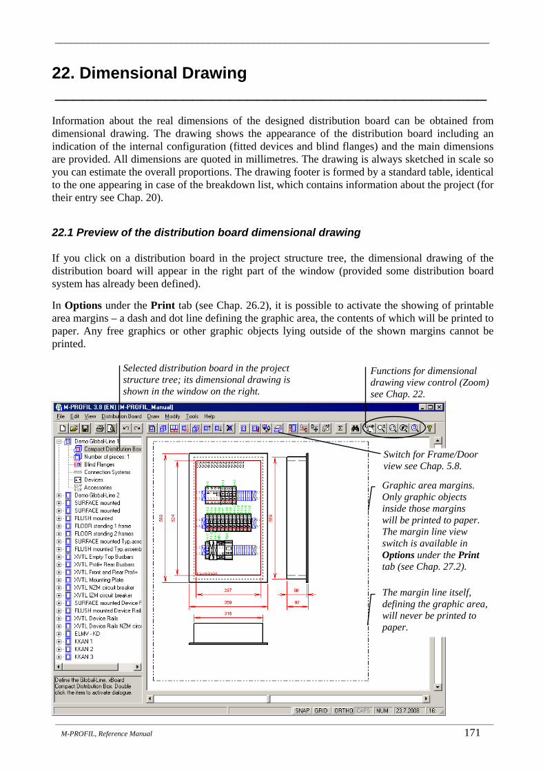
_______________________________________________________________________________
_______________________________________________________________________________________________________________________
M-PROFIL, Reference Manual 171
22. Dimensional Drawing _______________________________________________
Information about the real dimensions of the designed distribution board can be obtained from dimensional drawing. The drawing shows the appearance of the distribution board including an indication of the internal configuration (fitted devices and blind flanges) and the main dimensions are provided. All dimensions are quoted in millimetres. The drawing is always sketched in scale so you can estimate the overall proportions. The drawing footer is formed by a standard table, identical to the one appearing in case of the breakdown list, which contains information about the project (for their entry see Chap. 20).
22.1 Preview of the distribution board dimensional drawing If you click on a distribution board in the project structure tree, the dimensional drawing of the distribution board will appear in the right part of the window (provided some distribution board system has already been defined).
In Options under the Print tab (see Chap. 26.2), it is possible to activate the showing of printable area margins – a dash and dot line defining the graphic area, the contents of which will be printed to paper. Any free graphics or other graphic objects lying outside of the shown margins cannot be printed.
Selected distribution board in the project structure tree; its dimensional drawing is shown in the window on the right.
Functions for dimensional drawing view control (Zoom) see Chap. 22.
Switch for Frame/Door view see Chap. 5.8.
Graphic area margins. Only graphic objects inside those margins will be printed to paper. The margin line view switch is available in Options under the Print tab (see Chap. 27.2).
The margin line itself, defining the graphic area, will never be printed to paper.

_______________________________________________________________________________
_______________________________________________________________________________________________________________________
172 M-PROFIL, Reference manual
22.2 Printing the distribution board dimensional drawing
1. Select the Print item from the File drop-down menu or click on the corresponding icon in the tool bar.
2. A dialogue panel will open, in which you specify which drawing you want to be printed (similarly to the breakdown list preview procedure - see Chap. 21.1), set the required number of copies and click OK. Tip: it is sufficient to double click on the selected item.
3. Specify the output device for print.
Notes:
• In case the print results are not satisfactory, check the scale settings. • The dimensional drawing can be printed:
• To automatically defined scale: the dimensional drawing is reduced or enlarged so that it fully fills the defined drawing area (maximum to area);
• To a fixed user-defined scale. • The scale setting can be changed in Options under the Print tab – see Chap. 26.2.
• The thickness of lines in the dimensional drawing can be modified in Options under the Print tab – see Chap. 26.2.
Information about the currently set output device type, to which the list will be printed.
Changing the properties of the currently set output device type, to which the list will be printed (changing the type, port, paper size, paper orientation, ...).
Execution of the print to the currently set output device type.
Forced interruption of the function without print execution.
The required number of copies is already set in the previous dialogue panel; leave the value of 1 here.
Settings of breakdown list generation and print parameters, for more details see Chap. 25.1, 25.2.
Dimensional drawing for the currently edited distribution board will be printed – only one drawing.
Dimensional drawings for all distribution boards in the project will be printed – several drawings depending on the number of distribution boards in the project
Required number of copies of the dimensional drawing.
The breakdown list and the dimensional drawing are printed at one go, with one click.
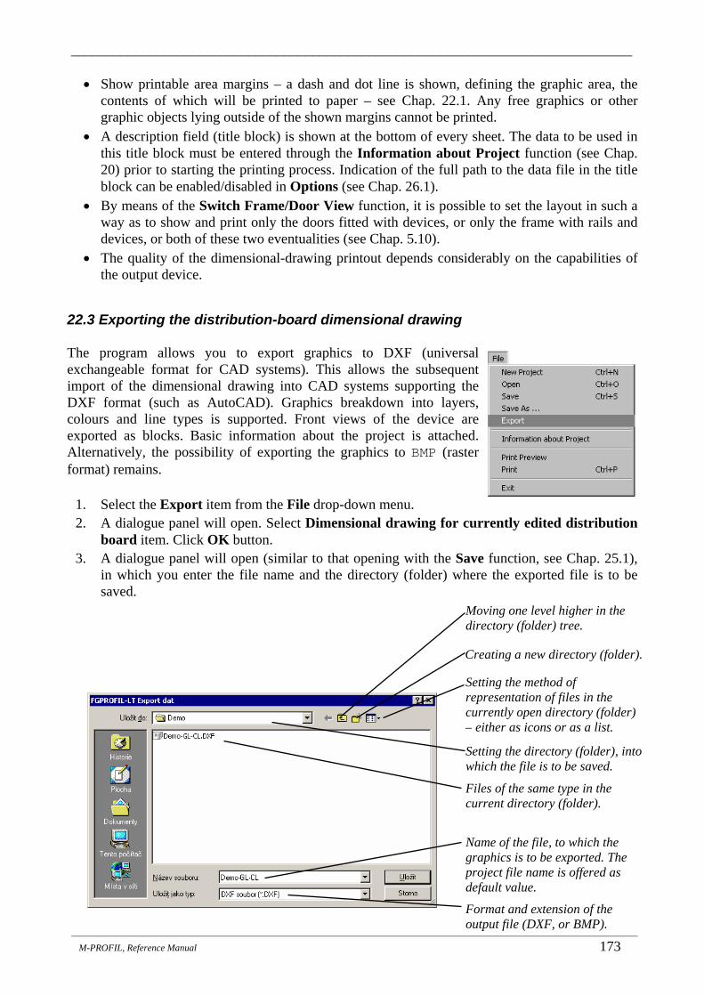
_______________________________________________________________________________
_______________________________________________________________________________________________________________________
M-PROFIL, Reference Manual 173
• Show printable area margins – a dash and dot line is shown, defining the graphic area, the contents of which will be printed to paper – see Chap. 22.1. Any free graphics or other graphic objects lying outside of the shown margins cannot be printed.
• A description field (title block) is shown at the bottom of every sheet. The data to be used in this title block must be entered through the Information about Project function (see Chap. 20) prior to starting the printing process. Indication of the full path to the data file in the title block can be enabled/disabled in Options (see Chap. 26.1).
• By means of the Switch Frame/Door View function, it is possible to set the layout in such a way as to show and print only the doors fitted with devices, or only the frame with rails and devices, or both of these two eventualities (see Chap. 5.10).
• The quality of the dimensional-drawing printout depends considerably on the capabilities of the output device.
22.3 Exporting the distribution-board dimensional drawing The program allows you to export graphics to DXF (universal exchangeable format for CAD systems). This allows the subsequent import of the dimensional drawing into CAD systems supporting the DXF format (such as AutoCAD). Graphics breakdown into layers, colours and line types is supported. Front views of the device are exported as blocks. Basic information about the project is attached. Alternatively, the possibility of exporting the graphics to BMP (raster format) remains.
1. Select the Export item from the File drop-down menu. 2. A dialogue panel will open. Select Dimensional drawing for currently edited distribution
board item. Click OK button. 3. A dialogue panel will open (similar to that opening with the Save function, see Chap. 25.1),
in which you enter the file name and the directory (folder) where the exported file is to be saved.
Format and extension of the output file (DXF, or BMP).
Files of the same type in the current directory (folder).
Setting the directory (folder), into which the file is to be saved.
Name of the file, to which the graphics is to be exported. The project file name is offered as default value.
Moving one level higher in the directory (folder) tree.
Creating a new directory (folder).
Setting the method of representation of files in the currently open directory (folder) – either as icons or as a list.

_______________________________________________________________________________
_______________________________________________________________________________________________________________________
174 M-PROFIL, Reference manual
4. Click Save to close the dialogue panel. The dimensional drawing will be exported to the file of the selected format.
Note:
• By means of the Program Setting function, the Export to DXF tab, it is possible to set the layer colours and thus also the colours of the individual graphical objects to be exported to the DXF file (see Chap. 26.7).
• By means of the Program Setting function, the Breakdown List tab, the indication of the data file complete path in the description field can be turned on/off (see Chap. 26.1).
• By means of the Program Setting function, the Export do DXF tab, it is possible to define the DXF file compatibility with various AutoCAD versions (see Chap. 26.7). It is advisable to change the setting if you have difficulties with loading the created DXF file.
• By means of the Program Setting function, the Export do DXF tab, the export of the summary information about the distribution board can be turned on/off (see Chap. 26.7) – this summary information can also be shown by means of the Information about the Type of the Edited Distribution Board function (see Chap. 5.9).

_______________________________________________________________________________
_______________________________________________________________________________________________________________________
M-PROFIL, Reference Manual 175
23. View Control (Zoom) _______________________________________________
The view control (zooming in and out in the design sections) is based on the method of operation applied in CAD systems (such as AutoCAD). The program makes drawings in area having the dimensions of infinity x infinity. The screen of your monitor is only like a zooming glass, a “peep-hole” through which you look at a part of the infinite drawing area. Depending on if the zooming glass is further from or closer to the area, you see a larger or smaller part of the design in it, with smaller or larger details. The individual functions can be activated from the View drop-down menu, or by clicking on the appropriate icon in the tool bar or from the pop-up context menu, as the case may be, which is displayed after clicking the right mouse button inside the graphics area.
23.1 Regenerating images
1. Select the Regen item from the View drop-down menu. 2. The image will be regenerated - image faults will be eliminated. It is recommended to be used
e.g. after changing the main program window dimensions by dragging its edge or in case of faulty image of the dimensional drawing after a non-standard termination of editing operation.
23.2 Pan
1. Select the Pan item from the View drop-down menu or click on the icon in the tool bar. 2. The pan mode is activated. The standard mouse pointer (usually an arrow) is changed
to the pan pointer (arrows up/down, left/right). Click to the image with your mouse, hold the left button down and move the mouse slowly. The dimensional drawing is dragged simultaneously with the mouse move. The fitted devices, blind flanges and side view of the Profi Plus distribution boards are not drawn during the move. Note: on slower computers, the movement can be jerky or the drawing might not move at all. In such case use the scroll bars at the side of the graphics area.
3. Release the left mouse button - the dimensional drawing will be repainted in the new position. 4. Press Esc to exit the pan mode (or click with the right mouse button and select Exit
Zoom/Pan from the pop-up context menu).
After editing: Before editing:
The mouse pointer shape in the Pan mode.
Scroll-bars to scroll through the distribution board drawing.
Click the left mouse button, hold it down and drag the mouse.
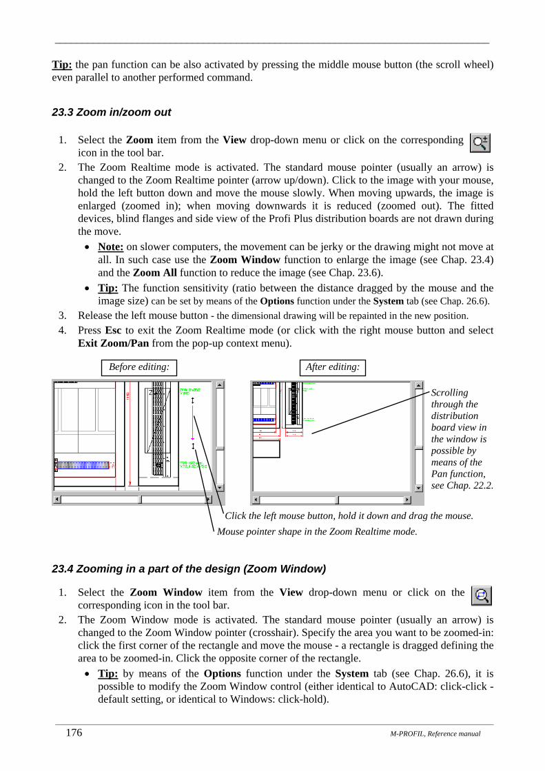
_______________________________________________________________________________
_______________________________________________________________________________________________________________________
176 M-PROFIL, Reference manual
Tip: the pan function can be also activated by pressing the middle mouse button (the scroll wheel) even parallel to another performed command.
23.3 Zoom in/zoom out
1. Select the Zoom item from the View drop-down menu or click on the corresponding icon in the tool bar.
2. The Zoom Realtime mode is activated. The standard mouse pointer (usually an arrow) is changed to the Zoom Realtime pointer (arrow up/down). Click to the image with your mouse, hold the left button down and move the mouse slowly. When moving upwards, the image is enlarged (zoomed in); when moving downwards it is reduced (zoomed out). The fitted devices, blind flanges and side view of the Profi Plus distribution boards are not drawn during the move. • Note: on slower computers, the movement can be jerky or the drawing might not move at
all. In such case use the Zoom Window function to enlarge the image (see Chap. 23.4) and the Zoom All function to reduce the image (see Chap. 23.6).
• Tip: The function sensitivity (ratio between the distance dragged by the mouse and the image size) can be set by means of the Options function under the System tab (see Chap. 26.6).
3. Release the left mouse button - the dimensional drawing will be repainted in the new position. 4. Press Esc to exit the Zoom Realtime mode (or click with the right mouse button and select
Exit Zoom/Pan from the pop-up context menu).
23.4 Zooming in a part of the design (Zoom Window)
1. Select the Zoom Window item from the View drop-down menu or click on the corresponding icon in the tool bar.
2. The Zoom Window mode is activated. The standard mouse pointer (usually an arrow) is changed to the Zoom Window pointer (crosshair). Specify the area you want to be zoomed-in: click the first corner of the rectangle and move the mouse - a rectangle is dragged defining the area to be zoomed-in. Click the opposite corner of the rectangle. • Tip: by means of the Options function under the System tab (see Chap. 26.6), it is
possible to modify the Zoom Window control (either identical to AutoCAD: click-click - default setting, or identical to Windows: click-hold).
After editing: Before editing:
Mouse pointer shape in the Zoom Realtime mode. Click the left mouse button, hold it down and drag the mouse.
Scrolling through the distribution board view in the window is possible by means of the Pan function, see Chap. 22.2.
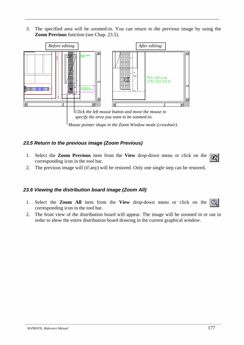
_______________________________________________________________________________
_______________________________________________________________________________________________________________________
M-PROFIL, Reference Manual 177
3. The specified area will be zoomed-in. You can return to the previous image by using the Zoom Previous function (see Chap. 23.5).
23.5 Return to the previous image (Zoom Previous)
1. Select the Zoom Previous item from the View drop-down menu or click on the corresponding icon in the tool bar.
2. The previous image will (if any) will be restored. Only one single step can be restored.
23.6 Viewing the distribution board image (Zoom All)
1. Select the Zoom All item from the View drop-down menu or click on the corresponding icon in the tool bar.
2. The front view of the distribution board will appear. The image will be zoomed in or out in order to show the entire distribution board drawing in the current graphical window.
After editing: Before editing:
Mouse pointer shape in the Zoom Window mode (crosshair).
Click the left mouse button and move the mouse to specify the area you want to be zoomed-in.

_______________________________________________________________________________
_______________________________________________________________________________________________________________________
178 M-PROFIL, Reference manual
24. Geometric Tools _______________________________________________
Geometric tools are designed for measurements in the dimensional drawing: The relevant functions are found in the Tools drop-down menu.
24.1 Distance measurement
1. Select the Distance item from the Tools drop-down menu. 2. The measurement mode is activated. The standard mouse pointer (usually an arrow) is
changed to the measuring pointer (crosshair). Click the first point in the image. 3. Click the other point. A dialogue panel appears showing the distance between the clicked
points. The determination of the point coordinates can be influenced by drawing tools (Grid, Snap and Ortho tools (see Chap. 16.7, 16.7.1)).
24.2 Determination of point coordinates
1. Select the Point Coordinates item from the Tools drop-down menu. 2. The measurement mode is activated. The standard mouse pointer (usually an arrow) is
changed to the measuring pointer (crosshair). Click the point in the image, the coordinates of which you want to determine. A dialogue panel appears indicating the point coordinates. The coordinate system origin is in the inner bottom left corner of the distribution box. The determination of the point coordinates can be influenced by drawing tools (Grid, Snap and Ortho tools). Also, the continuous indication of the cursor coordinates at the status line can be turned on (see Chap. 16.7, 16.7.1).
First clicked point.
Second clicked point
Delta Y
Delta X
Distance
Coordinate system origin = bottom left internal corner of the distribution box.
Clicked point

_______________________________________________________________________________
_______________________________________________________________________________________________________________________
M-PROFIL, Reference Manual 179
25. Working with Files _______________________________________________
The distribution board design can be continuously saved to a data file on your hard disk in order to keep the data for future editing. All information about the distribution board design is in a single file with the standard *.FGP extension and the name of the file is determined by the user. All operations with the files can be carried out by using the functions from the File drop-down menu or by means of the icons in the tool bar.
25.1 Saving your distribution board design to a file on the disk The current state of a distribution board design can be saved to a file located on the hard disk by means of the Save and Save As… functions from the File drop-down menu. When activating the Save function for the first time with no file name specified before, the user is required to enter the file name and directory (folder), where the file is to be saved. During the second and next calls of this function, all changes to the design are automatically saved to the data file, the name of which was entered during the first function activation. The name of the currently edited file is shown on top of the M-PROFIL dialogue panel. Every time the Save As… function is activated, the user is required to enter the file name and the directory (folder), where the file is saved. In this manner it is possible, for instance, to save the current design to a file with different name, thus, copying the original design to be used for further editing. The name of the currently edited file is shown on top of the M-PROFIL dialogue panel.
Setting the structure – format of the output file.
Files of the same type in the current directory (folder).
Setting the directory (folder), into which the file is to be saved.
Name of the file, to which the project is to be saved. The .FGP extension is attached automatically.
Moving one level higher in the directory (folder) tree.
Creating a new directory (folder).
Setting the method of representation of files in the currently open directory (folder) – either as icons or as a list.

_______________________________________________________________________________
_______________________________________________________________________________________________________________________
180 M-PROFIL, Reference manual
The current name of the edited file is shown on top of the M-PROFIL dialogue panel:
25.2 Loading (opening) a file with distribution board design A previously created data file with a distribution board design is loaded by means of the Open function from the File drop-down menu. First of all, the system performs the default state settings - checks whether the currently opened design was saved. If this is not the case, it will generate a message asking about their saving (see Chap. 25.3). In the next step, the user is asked for the directory (folder) and the file name:
The loaded file can be edited in any manner by using M-PROFIL tools. Notes:
• Reverse compatibility with older M-PROFIL versions is maintained, i.e. *.FGP files created in older program versions can be loaded in 3.x version, however, files from the current version cannot be loaded in older and read versions.
• When loading files created in previous version, Moeller devices that are not manufactured anymore will be replaced automatically with their new equivalents. The user is informed on the result through a table of substitutions, which is shown for every distribution board in the loaded project:
Name of the edited file.
Setting the structure – format of the loaded file.
Files with the existing projects in the current directory (folder). Click on the file name you want to open.
Setting the directory (folder), from which the file is to be loaded.
Name of the file you want to open, the .FGP extension does not have to be specified.
Moving one level higher in the directory (folder) tree.
Setting the method of representation of files in the currently open directory (folder) – either as icons or as a list.

_______________________________________________________________________________
_______________________________________________________________________________________________________________________
M-PROFIL, Reference Manual 181
25.3 Editing a new distribution board If you want to start editing a new distribution board = set the program to the default state, use the New Project command from the File drop-down menu. First of all, the system checks whether the currently opened design was saved. If this is not the case, it will generate a message asking about its saving:
Depending on the user’s response, it will set the default state of the program (identical situation as if you would exit the program - see Chap. 25.4 and launch it again - see Chap. 3.2).
Activates the Save function automatically (see Chap. 24.1) to save the current state of the design to your hard disk. Afterwards it continues in the New function.
Does not save the current state of the device anywhere and continues directly in the New function.
Forced interruption of the function; nothing happens and it ispossible to continue in editing of the current project.
Name of the distribution board in the project.
Original device.
Method of substitution: if no equivalent was found, the device is not loaded; if some equivalent was found, the device was replaced; if the device is still produced, it is left here without change.
Identification of the device in the distribution board.
Item that is used as substitution of the original device, which is not manufactured anymore.
Drag the edges of the dialogue panel to change its dimensions.
Drag the partitions in the table header to adjust the column width.
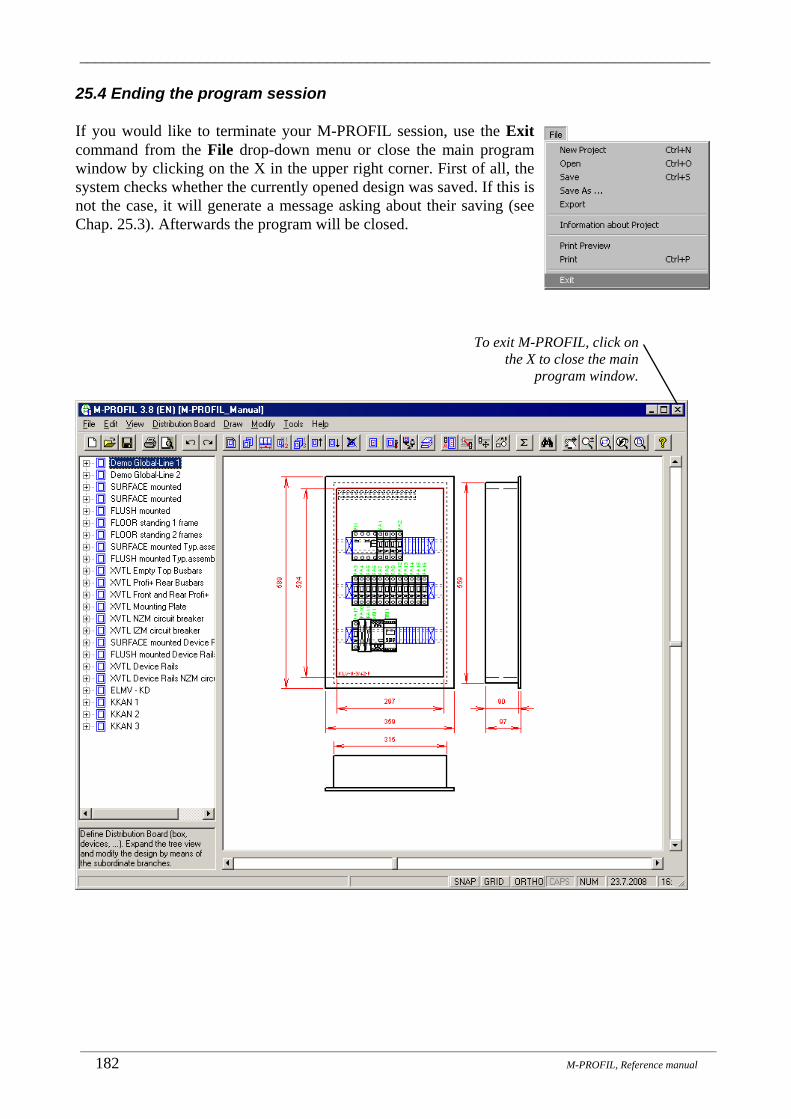
_______________________________________________________________________________
_______________________________________________________________________________________________________________________
182 M-PROFIL, Reference manual
25.4 Ending the program session If you would like to terminate your M-PROFIL session, use the Exit command from the File drop-down menu or close the main program window by clicking on the X in the upper right corner. First of all, the system checks whether the currently opened design was saved. If this is not the case, it will generate a message asking about their saving (see Chap. 25.3). Afterwards the program will be closed.
To exit M-PROFIL, click on the X to close the main
program window.

_______________________________________________________________________________
_______________________________________________________________________________________________________________________
M-PROFIL, Reference Manual 183
26. Options _______________________________________________
The Options function allows you to set the global variables affecting the program behaviour as a whole in an easy way by means of a dialogue panel. The particular setting features defined in the function are recorded in the system and maintained until their next change regardless of the edited project. The individual setting features are saved in the M-PROFIL.INI file in the program root directory. The file may not be write-protected.
26.1 Setting the breakdown list generation algorithm The Options function allows you to modify the parameters of breakdown list generation and its form. Therefore it is possible to meet various requirements on the breakdown list form (division in pages, indication of prices, …) as well as on the generating method (quantity rounded up to packages, price coefficient specification, …).
1. Select the Options item from the Tools drop-down menu. 2. A dialogue panel will open, in which you click on the Breakdown List tab. A dialogue panel
for the breakdown list configuration appears:
• Round the quantity of components to full packages: Some components are supplied in fixed packages containing a certain number of components. These packages cannot be divided further into smaller parts (this concerns primarily some components from the category of accessories). When determining the quantity of a component, the following situations are possible: • if this item is ticked, the quantity will be rounded with respect to package size and the
number of packages will be indicated in the breakdown list whereas the price will be determined as a multiple of the price for the full package;
Settings for the breakdown list generation algorithm. For more detail see below.
Settings for the method of sorting the components in the breakdown list.
Settings of discounts and surcharges for the individual component groups, for more details see Chap. 21.5.
Possibility to modify the algorithm of the breakdown list generation and column arrangement for the export to Excel

_______________________________________________________________________________
_______________________________________________________________________________________________________________________
184 M-PROFIL, Reference manual
• if this item is NOT ticked (recommended), no rounding will be performed and the actual required quantity of components will be indicated whereas the price will be determined as the price for the actually needed quantity of components even if this concerns a package fraction.
• Note: quantity of some components (BPZ-MSW side wall, BEL fastening element, TIW depth strap, SSN support, ...) is always rounded with respect to package size, regardless off settings this switch.
• Specify prices for the particular components in the breakdown list: • if this item is ticked (recommended), prices will be indicated in the breakdown list as
calculated according to the price list and adjusted according to the settings of discounts and surcharges;
• if this item is NOT ticked, the component prices will not be indicated in the breakdown list.
• Print the total price of the distribution board/project in the breakdown list: • if this item is ticked (recommended), the total price of the distribution board or project
(calculated according to the setting of the previous switches) will be printed automatically in the footer of every breakdown list page;
• if this item is NOT ticked, the total price of the distribution board/project will not be indicated in the breakdown list (modified information about the total price can be entered, for instance, in the “Note” field through the “Information about Project” function (see Chap. 20).
• Indicate the information message on prices in the breakdown list: • if this item is ticked (recommended), the following message will be indicated in the
footer of every breakdown list page: “Price calculation is based on the offer prices of Moeller; the purchase price will be determined by Moeller business partners.”
• if this item is NOT ticked, the message specified above will not be printed. • Show the Path to the Data File in the breakdown list/dimensional drawing:
• If this item is ticked, the name of the data file, including the complete path to the file (e.g. c:\M-PROFIL\Demo\Demo-GL-CL.FGP), will be included in the footer of each breakdown list and of each dimensional drawing.
• If this item is NOT ticked (recommended), only the name of the data file, without the path, will be included (e.g. Demo-GL-CL.FGP)
• Export of the breakdown list to Excel: The arrangement of the columns for the export of the breakdown list to the format for Excel can be set as follows: • In the M-PROFIL standard arrangement – the arrangement of the columns is
identical with that of the breakdown list preview or with that of the direct printout on paper.
• The price per piece and indication of the group for a discount are also included – in comparison with the standard breakdown list, the breakdown list will have the additional ‘Price per Piece’ column, which contains the unit price for each item, regardless of the setting of discounts and surcharges, and the ‘Group’ column, which contains the identification of the group of goods for a discount (discount group). If the Moeller purchase prices have been filled in the price list, the columns ‘Moeller Purchase Price per Piece’, ‘Moeller Purchase Price in Total’ and ‘Margin’ are also filled in. Also, the total margin for the given distribution board or for the whole project is computed.
• In the arrangement according to the Moeller Price List application – the arrangement of the columns is identical with the arrangement for the export of an offer that has been

_______________________________________________________________________________
_______________________________________________________________________________________________________________________
M-PROFIL, Reference Manual 185
created in the Moeller Price List application. The Excel table contains formulas; a recalculation is carried out automatically whenever the price or discount value changes. If the recalculation does not take place, it is necessary to set the point as the decimal separator in Windows (Start – Settings – Control Panels – Regional and Language Options).
• Sort components in the breakdown list - here you can set how the components will be sorted in the breakdown list. The options available are alphabetically according to description, alphabetically according to type or no sorting - in such case the components will be arranged in the same order as in the internal database of M-PROFIL system. Note: it may take a longer period of time to sort larger breakdown lists depending on the computer performance.
3. Set the individual items as desired. 4. Close the dialogue panel by clicking OK. The entered setting features will be recorded in the
system and will remain saved even after program termination.
26.2 Print settings
1. Select the Options item from the Tools drop-down menu. 2. A dialogue panel will open, in which you click on the Print tab. A dialogue panel for the
print configuration appears:
• Number of lines per page represents the number of components in the breakdown list, which will be printed on one page - the number of header and footer lines.
• Left margin width in characters indicates the number of spaces between the left paper edge and the beginning of the first printed character on the line.
• Font height in points indicates the font height in the printed version of the breakdown list. The recommended value is 8. It is not advisable to use smaller values. If you decide to use different font height, it is necessary to adjust the number of lines per page and the left margin width accordingly to ensure that all data are printed on the paper. The paper size, format and
Set line thickness for graphic objects for the screen and the printer. Double click on the respective line and enter new values.
Color of the object on the screen, facilitates orientation in the table.
Values dependant on the paper size and its orientation.

_______________________________________________________________________________
_______________________________________________________________________________________________________________________
186 M-PROFIL, Reference manual
orientation are set not sooner than during the actual print by modifying the printer properties (the Change button in the Print dialogue panel - see Chap. 21.1 and 22.2). The table below indicates examples of the recommended settings:
Format Orientation Lines per page Left margin Font height
A4 portrait 65 4 8 A4 landscape 18 2 12 A3 portrait 36 2 12
• Print the breakdown lists of components for distribution boards, devices and accessories
always on new page - if this item is ticked, no paging will be carried out after printing the breakdown list of frame components and the list of devices will be printed immediately behind the list of the mechanical components of the frame.
• Printable area margins – if this item is ticked, a dash and dot line will appear defining the graphic area, the contents of which will be printed to paper. Any free graphics or other graphic objects lying outside of the shown margins cannot be printed.
• Print to fixed scale:
• if this item is ticked, a fix user-defined scale will be used to print the dimensional drawing – i.e. the value at the right of the switch. The scale 1:10 means that 1 mm on paper corresponds to 10 mm of the distribution board (reduction 10x). The suitability of the entered scale for the currently printed distribution board needs to be verified by printing a test copy.
Distribution board: 359x464x130
Distribution board: 444x764x245
Print to fixed scale.

_______________________________________________________________________________
_______________________________________________________________________________________________________________________
M-PROFIL, Reference Manual 187
• if this item is NOT ticked, an automatically defined scale will be used to print the dimensional drawing so that the dimensional drawing fully fills the defined drawing area (maximum to area). It is guaranteed that the entire distribution board will be printed to the current paper.
• Line thickness: set line thickness for graphic objects for the screen and the printer. Double click on the respective line in the table and enter new values in the dialogue panel. The line thickness must be tested for suitability.
3. Set the individual items as desired. 4. Close the dialogue panel by clicking OK. The entered setting features will be recorded in the
system and will remain saved even after program termination.
Distribution board: 359x464x130
Distribution board: 444x764x245
Print to automatically determined scale “scale to fit”.

_______________________________________________________________________________
_______________________________________________________________________________________________________________________
188 M-PROFIL, Reference manual
26.3 Changing the licence data
1. Select the Options item from the Tools drop-down menu. 2. A dialogue panel will open, in which you click on the Licence tab. A dialogue panel appears
enabling you to enter the licence data:
3. Set the individual items as required. 4. Close the dialogue panel by clicking OK. The entered setting features will be recorded in the
system and will remain saved even after program termination.
Possibility to enter new licence data (user identification, licence number and licence expiration date) by means of a dialogue panel identical to the one used during the first program initialization (see Chap. 3.1).
Current licence data. Settings of the national program version. The current settings are displayed in the top line in the main panel. The switch influences the language, national price list version and display of addresses for local representation of the provider.
Name of the currently open file. Current national version of the program.
Current program version.
Show the Licence Agreement applying to the use of the software. The Licence Agreement appears, as standard, during the first initialization of the program and it is not possible to launch the program without agreeing to its terms. This button allows you to look at the text of the Agreement at a later point in time.
Date of the last automatic check for updates from the Moeller website. For more details see Chap. 2.4.

_______________________________________________________________________________
_______________________________________________________________________________________________________________________
M-PROFIL, Reference Manual 189
26.4 Price list - currency and exchange rate
1. Select the Options item from the Tools drop-down menu. 2. A dialogue panel will open, in which you click on the Price List tab. The following dialogue
panel appears allowing you to set the price list parameters:
3. Set the individual items as desired. 4. Close the dialogue panel by clicking OK. The entered setting features will be recorded in the
system and will remain saved even after program termination.
Note: the Czech version of M-PROFIL always includes an up-to-date price list prepared in CZK. Changes in the parameters described above are thus necessary only when the program is used outside of the Czech Republic.
26.5 Distribution Boards
1. Select the Options item from the Tools drop-down menu. 2. A dialogue panel will open, in which you click on the Distribution Boards tab. A dialogue
panel appears allowing you to set additional parameters of the distribution board systems:
3. Set the individual items as desired. 4. Close the dialogue panel by clicking OK. The entered setting features will be recorded in the
system and will remain saved even after program termination.
The effect of the settings will show when inserting DIN rails into Profi Plus distribution boards.
The effect of the settings will show when inserting Moeller devices, RMQ command and signalling elements, third-party devices, terminal blocks and connecting sleeves.
Select the supported distribution board system for stand-alone distribution boxes of 2,000 mm height. The settings are determined by the regional version of the program and cannot be modified by the user.
Scope of the product range offered. The settings are determined by the regional version of the program and cannot be modified by the user.

_______________________________________________________________________________
_______________________________________________________________________________________________________________________
190 M-PROFIL, Reference manual
26.6 System settings
1. Select the Options item from the Tools drop-down menu. 2. A dialogue panel will open, in which you click on the System tab. A dialogue panel appears
allowing you to set additional program parameters:
Show Tips of the Day after program startup: if this item is ticked, the window with the tips of the day, topics for working with the
program, new features in the current version, etc. will be shown after every program startup;
if this item is NOT ticked, the window with the tips of the day will not be shown. The tips of the day can be shown at any time using the Tip of the Day function from the Help drop-down menu (see Chap. 27.1).
Cursor in the form of crosshair: if this item is ticked, the cursor will have the shape of a crosshair, as in AutoCAD; if this item is NOT ticked, the cursor will have the shape of an arrow.
After Clicking on the button, a standard dialogue panel will be displayed, as in the function Open; use this panel to find the Adobe Reader program’s executable file AcroRd32.exe. The program installation files are available at the installation CD or can be downloaded free of charge from the Internet address www.adobe.com.
Cursor in the form of arrow Cursor in the form crosshair
Restoration of the default positionof floating windows can be used, for instance, when the window with the calculation results appears outside of the screen (suitable also when an external screen is disconnected from laptop).

_______________________________________________________________________________
_______________________________________________________________________________________________________________________
M-PROFIL, Reference Manual 191
• ZoomWindow control: • if this item is ticked, the control of the ZoomWindow function and the selection of
components to be edited by means of selection windows will be the same as in AutoCAD (click the coordinates of the first window corner, drag a rectangle with the mouse and then click the coordinates of the second corner).
• if this item is NOT ticked, the control of the ZoomWindow function and the selection of components to be edited by means of selection windows will be the same as in Windows (it is necessary to click the coordinates of the first window corner, keep the left mouse button pressed, drag a rectangle and release the left mouse button at the point of the second corner).
• Automatic saving: • if this item is ticked, a backup of the currently processed project will be created
automatically at the defined time interval. The backup file name is identical to the project file name. The backup is created in an auxiliary directory depending on the settings of the system variable TEMP (typically: ...user...\Local Settings\Temp). • In case of a standard changeover to another project or when the project is opened
again, the previous backup is deleted. • Immediately after a failure, the backup file must be transferred to the current
directory. • Immediately after a failure, do not attempt to open the processed project again – by
doing this, the backup would be deleted. • This function serves as a backup for computer or system failures. In no case it
replaces project saving on a regular basis by means of the Save function. • Setting a too short interval for automatic saving can hinder the program
functionality. • if this item is NOT ticked, the automatic backup will not be created.
• Adobe Reader is necessary to view the help and other files in PDF format. After clicking on the button, a standard dialogue panel will appear as in the Open function, allowing you to find the executable file for Adobe Reader AcroRd32.exe. The program installation is available on the installation CD-ROM or can be downloaded for free on the Internet at www.adobe.com.
• Automatic Update: set the time interval to check the availability of new software versions on the Moeller website. After the defined number of days goes by, the program will automatically connect to the Moeller website and check the availability of new software versions. If a new version is available, it will be downloaded and installed automatically. For more details see also Chap. 2.4.
3. Set the individual items as needed. 4. Close the dialogue panel by clicking OK. The entered setting features will be recorded in the
system and will remain saved even after program termination.

_______________________________________________________________________________
_______________________________________________________________________________________________________________________
192 M-PROFIL, Reference manual
26.7 Export to DXF file format
1. Select Options in the Tools menu 2. A dialogue panel will open, in which you click on the System tab. A dialogue panel will
appear allowing you to set additional program parameters:
• DXF version: it is possible to set the DXF format compatibility with the relevant AutoCAD version. If you are not able to open the created DXF file in your CAD system, try to change the setting of this item.
• Export summary info about the distribution board: • if this item is ticked, the summary information about the distribution board – otherwise
shown using the function Information about type of edited distribution board (see Chap. 5.9) – will be exported to DXF file.
• if this item is NOT ticked, the summary information about the distribution board will not be exported to DXF file (suitable e.g. when inserting a dimensional drawing of the distribution board to a wiring diagram).
• Layer colours: when being exported to DXF, graphic objects are divided to layers. The colour of the objects corresponds to the colour of the layer where the object is found. When printing from CAD system, specific line thickness is assigned to every colour. It is possible to assign different colours according to the custom of every user. • Double click on the name of the layer, the colour of which you want to change. • A dialogue panel will open, in which you select a new colour from the colour range.
Then click OK. The colour range shows only ACI colours supported by all versions of AutoCAD and other CAD systems.
Set layer colors for export to DXF format. Double click on the respective line and select a new color from the color range.
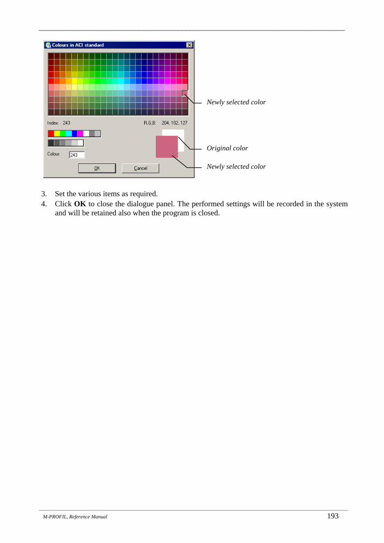
_______________________________________________________________________________
_______________________________________________________________________________________________________________________
M-PROFIL, Reference Manual 193
3. Set the various items as required. 4. Click OK to close the dialogue panel. The performed settings will be recorded in the system
and will be retained also when the program is closed.
Newly selected color
Original color
Newly selected color

_______________________________________________________________________________
_______________________________________________________________________________________________________________________
194 M-PROFIL, Reference manual
27. Help _______________________________________________ The Help Topics function from the Help drop-down menu launches Adobe AcrobatReader with the electronic version of this manual in PDF format. In order to ensu,re correct operation of this function, you must set the full path for the executable AcrobatReader file AcroRd32.exe by means of the Options function (see Chap. 26.6). If you do not have Adobe AcrobatReader installed on your computer yet, you can find its setup on the installation CD or you can download it from the Internet at www.adobe.com.
27.1 Tip of the Day The Tip of the Day function from the Help drop-down menu activates the Tip of the Day window showing the topics and recommendations for working with the program:
Notes:
You enable / disable the function for showing tips at every program startup by means of the Options function from the Tools drop-down menu (under the System tab) - see Chap. 26.6.
The system remembers the last shown tip, therefore, the next available tip appears when you activate the Tip of the Day window next time (whether at the program startup or through the Tip of the Day function from the Help drop-down menu).
The list of all tips is saved in the ...\TipDne.txt data file. The individual tips are separated by <> characters in the beginning of the line. The file can be printed out by using the operating system tools.
Close the Tip of the Day window and return to the M-PROFIL environment.
Move to the next tip. When the last tip has been shown, the whole series starts from the beginning.
Tip text – topics and recommendations for working with the program.
Switch that determines whether the window with tips should be shown automatically at the program startup.

_______________________________________________________________________________
_______________________________________________________________________________________________________________________
M-PROFIL, Reference Manual 195
28. About M-PROFIL _______________________________________________ The About M-PROFIL function from the Help drop-down menu is a function designed to view information about the application - the M-PROFIL system. The function can be used to determine the licence information.

______________________________________________________________________________________________
_______________________________________________________________________________________________________________________
196 M-PROFIL, Reference Manual
29. History of Versions _______________________________________________ 1. Version 1.0, November 1997
The first beta-version of the system presented at the MSV Brno ‘97 Fair. The first live version of the system available for distribution from November 1997.
2. Version 3.3, September 2003 The first English language version of the system available for distribution from November 2003.
…
3. Version 3.8, September 2008 In general:
M-PROFIL (formerly FGPROFIL-LT) contains an implementation of the distribution board systems Profi Plus (which replaced the Profi-Line system) and XVTL (which replaced the SVTL system). All other databases have also been updated.
Reverse compatibility ensured: projects from older FGPROFIL-LT versions (versions 3.6 and 3.7) can be loaded.
Xboard distribution boards, boxes with higher IP protection Product range updated:
Flush-mounted Global-Line compact distribution boxes of U-series replaced with a new KLV-U- series. Accessories product range updated.
Profi-Line distribution boards Replaced with the Profi Plus distribution board system
SVTL distribution boards: Replaced with the XVTL distribution board system
xEnergy distribution boards: No change
Database of installation devices Database updated: New types of dimmers DS-TA and TS-TD replace and extend the original DS-GS series. New types of analog clock switch SU-TS and SU-TQ replace the original SU-GS, SU-GQ series. Residual current devices added - sets for networks TN-S, TT: SPB-3+1, SPC-S-3-N/PE. Antenna residual current devices SPC-MS/SAT added. PLI-series circuit-breakers with spring terminals removed.
Database of connecting sleeves (interconnection bridges, N/PE terminal blocks) Database updated:
New types of terminal blocks added - BPZ-KB-...-ALU for both aluminium and copper conductors Database of industrial devices
Database updated: NZM-series power circuit-breakers:
Base for withdrawable version added for NZM1 (NZM1-XSVS) NZM1...-XSVS circuit-breakers added, with an adapter for withdrawable version NZM2...-XSVS circuit-breakers added, with an adapter for withdrawable version NZM2...-FIA30 circuit-breakers added - 3-pole circuit-breakers with fault-current release NZM3.-A circuit-breakers added, with thermomagnetic release NZM3.-S circuit-breakers added, to protect motors without overload release NZM3...-BT circuit-breakers added, with pre-installed clamp-type terminals Economical versions of NZM2-XRD motor drives added for NZM2 circuit-breakers Small accessories added (-XBRS panels).
RMQ command and signalling devices: M22-CK01, 10, 11 double contacts added.

______________________________________________________________________________________________
_______________________________________________________________________________________________________________________
M-PROFIL, Reference Manual 197
M22-WJ..-2P two-position joystick added. Small accessories added.
EMR4 measurement and monitoring relays New versions of EMR4-I...-1 and WMR4-W...-1- added.
Easy relays: EASY-410 input and output extension added. New types of power supply units EASY-...-POW added, repair and clarification of dim. drawings.
Contactors, contactor combinations, overcurrent relays: New types added - DILM38 (38A, 18.5kW), DILH2200 (2200A). Star-delta contactor combinations - new types SDAINLM 70...260 (70...260A, 37...132kW) added.
Overcurrent relays: New types ZB32-38 and ZB65-75 added. Small accessories added.
PKZ motor starters Small accessories added.
User-defined database of terminal blocks Update and significant expansion of the offered range of Wago terminal blocks (this will show only if no
transfer of user-defined databases from a previous version is requested during the installation) Working with the list of selected devices
New option added, allowing the user to copy the selected devices between distribution boards within the project as well as between projects using the program's internal clipboard.
Accessories database No change.
Price list: New allocation of discount groups. Weights updated. Prices updated.
4. M-PROFIL, Version 3.9.01, July 2009 System All corrections, improvements and changes, released during last year, were implemented to the compilation (see
ReadMe.txt file for details). A function added to automatically check for new software versions available on the Moeller website (Updater) at
a customizable time interval (from version 3.8.10). New version of Updater was implemented; possibility to update software from local directory (not only from web) was addend (from version 3.9).
Button "Restore default positions of flying windows" was added to Options function from Tools menu, System tab. This button is useful in case of using software on hardware with different resolution of graphics (for example notebook and notebook with external monitor). When you move to hardware with lower resolution of graphics, flying windows (for example list of selected devices, mounting rails, …) can be out of display and program looks as hanged; situation can be solved by clicking on this button.
If Excel version 2007 is installed on computer, files exported from M-Profil to Excel are saved "In compatibility mode Excel 97-2003". These files can be opened in Excel version 97 ... 2003 without any extra manipulation.
Distribution boxes xBoard, cabinets with higher degree of protection Assortment was updated
Distribution boards Profi Plus, XVTL Assortment was updated
Distribution boards xEnergy No changes
Database of installation devices Assortment was updated
Database of industry equipment (industrial switchgear) Assortment was updated Eaton frequency inventors M-MAX, SPX, SVX types were added
Price list Weights updated. Power loses updated. Prices updated.

______________________________________________________________________________________________
_______________________________________________________________________________________________________________________
198 M-PROFIL, Reference Manual
5. M-PROFIL, Version 3.10.01, July 2010 In general: All corrections, improvements and changes, released during last year, were implemented to the compilation (see
ReadMe.txt file for details). New version of Updater has been implemented.
Distribution boards Profi Plus Floor standing distribution boards without door, 250mm depth, have been added (all combinations without door,
with sheet steel door or glassed door are possible). Distribution boards Profi Plus and XVTL Measuring devices 96L type can be fitted on the door by the same way as control and signalling devices RMQ-
titan type Busbar system SASY - Cu busbar 12x5mm, 160A, has been added.
xEnergy distribution boards: No change
Database of installation devices Extensive update of database of installation devices has been made (according to new catalogue "Installation
devices" valid from 1st June 2010 in Czech Republic): Digital residual current devices dRCM have been added. Residual current relay PDIM has been added. Combined devices MCB/RCD, PFL7 type - nominal currents up to 40A have been added (version EN/CZ,
RU/CZ). Combined devices MCB/RCD, mRB6 type, 3+N pole have been added. Modular circuit breakers, PLHT type, nominal currents from 20A-50A have been added (version EN/CZ,
RU/CZ). Other devices and accessories - assortment has been updated (new installation contactor 1TE width, low level
signals relay, switch for ampere meter, measuring current transformers, Boxes on DIN rail, measuring modules for network analysis, ...).
Fuses, fuse bases, fuse switch disconnectors - assortment has been updated and extended: (fuses D01, D02 and devices for fuses D01, D02 have been added; devices for DC applications have been added)
Surge voltage arresters - assortment has been updated. PV inverters for photovoltaic application have been added.
Database of industrial devices Measuring modules for network analysis NZM-XMC have been added (display NZM-XMC-DISP can be fitted as
"device on the door" by the same way as control and signaling devices RMQ-titan type). Motor-starter combinations with motor starters PKE type (with electronic release) have been added. Universal double adapters on SASY busbar system Z-SS-60-ADD/6... have been added.
Database of xComfort devices (version CZ only) Accessories database updated according to the client's instructions.
Price list: Weights updated Power loses updated Version EN/CZ and RU/CZ: New price list valid from 1st June 2010 has been added.
6. M-PROFIL, Version 3.11.01, July 2011 In general: All corrections, improvements and changes, released during last year, were implemented to the compilation (see
ReadMe.txt file for details). System: New version of Updater has been implemented. Possibility to set Server Time Out value has been added. Possibility to update software from local directory (not only from web) was improved.
Distribution boards Profi Plus Distribution board, surface mounted or floor mounted with BPZ-MSW side wall according to distribution board
height - possibility to fit DIN rails on the rear mounting frame has been added..

______________________________________________________________________________________________
_______________________________________________________________________________________________________________________
M-PROFIL, Reference Manual 199
Distribution boards XVTL Distribution box with Profi Plus front adapter and with Profi Plus rear adapter with BPZ-MSW side wall
according to distribution board height - possibility to fit DIN rails on the rear Profi Plus adapter has been added. xEnergy distribution boards: No change
Database of installation devices Obsolete devices have been removed.
Database of industrial devices Contactors DILM..-22(...) have been added. Obsolete devices have been removed.
Price list: Prices updated Weights updated Power loses updated

______________________________________________________________________________________________
_______________________________________________________________________________________________________________________
200 M-PROFIL, Reference Manual
Notes: