m3g2 angl papier - electro-acoustique
TRANSCRIPT

Electrodynamictransduction
Paternité - Pas d'Utilisation Commerciale - Partage des Conditions Initiales à l'Identique : http://creativecommons.org/licenses/by-nc-sa/2.0/fr/
ERIC BAVU, MARC PACHEBAT ET GUILLAUME PENELET

Table des matières
Objectifs 5
I - Elementary phenomena 7
A. An academic experiment...............................................................................7
B. Laplace force...............................................................................................8 1. The phenomena................................................................................................................8 2. Direction and orientation of the Laplace force........................................................................8
C. Lenz law: the phenomena.............................................................................9
D. Coupling in the harmonic domain.................................................................10 1. Electromotive force vs counter electromotive force?.............................................................10 2. Oscillatory domain (1/2)..................................................................................................10 3. Oscillatory domain (2/2)..................................................................................................10
E. What if we replace the rod with a membrane? The electrodynamic ribbon driver. 11
II - Axisymetrical geometry 13
A. How to make a transducer more compact?....................................................13
B. The moving coil electrodynamic loudspeaker..................................................14 1. Structure of a moving coil loudspeaker...............................................................................14 2. The loudspeaker as a generator (1/2)................................................................................17 3. The loudspeaker as a generator (2/2)................................................................................17 4. The loudspeaker as a sensor.............................................................................................17
C. Coupling equations of an electrodynamic loudspeaker.....................................18
III - Equivalent electrical representation 19
A. Equivalent network using a transformer........................................................19
B. Equivalent network using a gyrator..............................................................20
IV - Bibliography 21
V - Exit test: test your knowledge 23
VI - Exit test (answers) 25
Eric Bavu, Marc Pachebat and Guillaume Penelet 3


Objectifs
The objectives of this section are: to present the physical phenomena responsible for
electrodynamic transduction, without detailing theelectroacoustic foundations on which the phenomena is based;
to describe the phenomena through coupling equationslinking the electrical quantities (U,i) to the mechanical ones(F,v);
to express these coupling equations in the form of equivalentelectrical circuits.
The prerequired notion relative to this section are: some notions in electromagnetics (a complete comprehension
of this vast domain, is not mandatory however), modules 1 and 2 of this lecture.
Eric Bavu, Marc Pachebat and Guillaume Penelet 5


I - Elementary phenomena
I
An academic experiment 7
Laplace force 8
Lenz law: the phenomena 9
Coupling in the harmonic domain 10
What if we replace the rod with a membrane? Theelectrodynamic ribbon driver 11
A. An academic experiment
Consider the system shown in the following image, composed of a conductive rodwhich can roll along the axis . A U shaped magnet is placed between the two rails
.
This is an electromagnetic transduction system that can function as either agenerator (moving the rod along the rails will cause a current to circulate throughthe system) or as a receiver (the rod begins to rotate due the the electrical currentflowing through it).
Eric Bavu, Marc Pachebat and Guillaume Penelet 7

B. Laplace force
1. The phenomena
Firstly, we consider that an electrical current is flowing through the. Under the effects of the magnetic field and electrical
is applied to the rod.
, magnetic
, and the length of the rod . The movement is orientated so that
, and make up a direct othogonal basis:
represents the vector product. Hence, the consequence of the Laplace force is the movement of the rod.
This movement will also be influenced by any other exterior forces applied(friction, elasticiy, inertia).Remark: the length taken into account is that of the part bathed in themagnetic field. The rod could be twice as long, but if the same magnet isused, the force will be the same.
2. Direction and orientation of the Laplace force
There are three different methods to easliy find the direction and orientation of the
and notably, "the right hand rule".
Elementary phenomena
Eric Bavu, Marc Pachebat and Guillaume Penelet8

Right hand rule
The thumb and first two fingers of the right hand can be naturally made into andirect orthonormal base.
C. Lenz law: the phenomena
If we now consider that the rod is moving along the axis under the effect and
of the rod, a counter electromotive force is created acrossthe rod.
The potential is linked to a flux variation of the magnetic force defined by
Elementary phenomena
Eric Bavu, Marc Pachebat and Guillaume Penelet 9
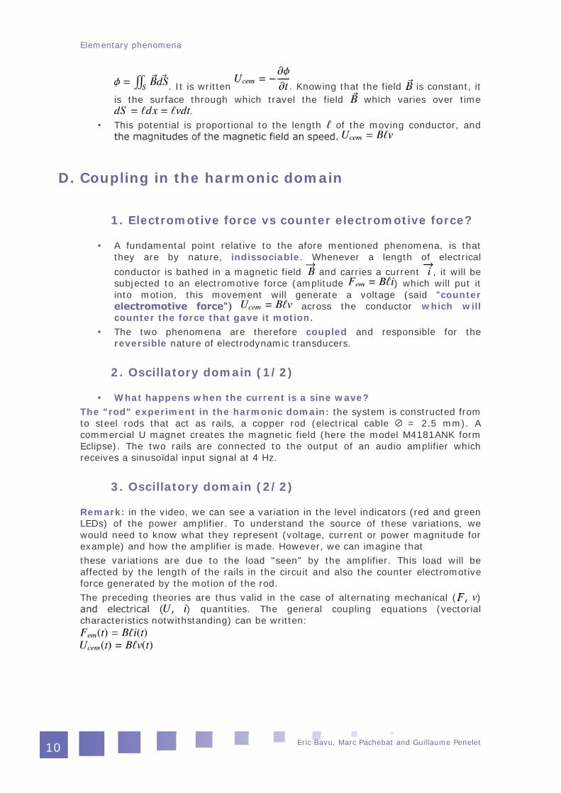
. It is written . Knowing that the field is constant, itis the surface through which travel the field which varies over time
. This potential is proportional to the length of the moving conductor, and
D. Coupling in the harmonic domain
1. Electromotive force vs counter electromotive force?
A fundamental point relative to the afore mentioned phenomena, is thatthey are by nature, indissociable. Whenever a length of electricalconductor is bathed in a magnetic field and carries a current , it will besubjected to an electromotive force (amplitude ) which will put itinto motion, this movement will generate a voltage (said "counter
across the conductor which willcounter the force that gave it motion.
The two phenomena are therefore coupled and responsible for thereversible nature of electrodynamic transducers.
2. Oscillatory domain (1/2)
What happens when the current is a sine wave? The "rod" experiment in the harmonic domain: the system is constructed fromto steel rods that act as rails, a copper rod (electrical cable = 2.5 mm). Acommercial U magnet creates the magnetic field (here the model M4181ANK formEclipse). The two rails are connected to the output of an audio amplifier whichreceives a sinusoïdal input signal at 4 Hz.
3. Oscillatory domain (2/2)
Remark: in the video, we can see a variation in the level indicators (red and greenLEDs) of the power amplifier. To understand the source of these variations, wewould need to know what they represent (voltage, current or power magnitude forexample) and how the amplifier is made. However, we can imagine thatthese variations are due to the load "seen" by the amplifier. This load will beaffected by the length of the rails in the circuit and also the counter electromotiveforce generated by the motion of the rod.The preceding theories are thus valid in the case of alternating mechanical ( )
) quantities. The general coupling equations (vectorialcharacteristics notwithstanding) can be written:
Elementary phenomena
Eric Bavu, Marc Pachebat and Guillaume Penelet10

E. What if we replace the rod with a membrane? The electrodynamic ribbon driver
By replacing the rod with a conductive membrane , the mechano-acousticalcoupling becomes more significant due to the large surface area of themechanical element (see the section on mechano-acoustical coupling) and aloudspeaker is created.
This type of loudspeaker (or microphone) is named "ribbon" loudspeaker.However,it is not widely used. The development of electrodynamictransducers has lead to the creation of several different and more efficientgeometries. These are tougher, and cheaper, but based on the sameprinciples. To the present day, the majority of electrodynamic transducersare based on a geometry of axial symmetry.
Principle of a ribbon transducer
Elementary phenomena
Eric Bavu, Marc Pachebat and Guillaume Penelet 11


II - Axisymetrical geometry
II
How to make a transducer more compact? 13
The moving coil electrodynamic loudspeaker 14
Coupling equations of an electrodynamic loudspeaker 18
A. How to make a transducer more compact?
Radial field and coiled conductorsA way of increasing the transduction efficiency is to increase the length of theconductor contained in the magnetic field . To maintain a certain compactness, asolution is to wind the conductor into a coil, which in turn means rethinking thespatial distribution of the magnetic field , which should present a radial structure,centered on the coils axis.
Eric Bavu, Marc Pachebat and Guillaume Penelet 13

Small excercise: Verify, with the help of the 3 finger rule, that the direction, andorientation of the Lapalce forces shown on the image below are correct.
(be careful not to sprain your wrist...).
B. The moving coil electrodynamic loudspeaker
1. Structure of a moving coil loudspeaker
The conventional architecture, dating back to the 1925 patent by Rice & Kellog, iscomprised of a coil attached to a membrane, and placed in a radial magnetic field.
Photography of the patented design from Chester W. Rice and Edward W. Kellogg(brevet No. 1,812,389)
Axisymetrical geometry
Eric Bavu, Marc Pachebat and Guillaume Penelet14

Photographies of a commercial loudspeaker:
Loudspeaker without membrane
Axisymetrical geometry
Eric Bavu, Marc Pachebat and Guillaume Penelet 15

Loudspeaker without spider
Axisymetrical geometry
Eric Bavu, Marc Pachebat and Guillaume Penelet16

Coil removed from the motor
2. The loudspeaker as a generator (1/2)
In the following videos, a commercial electrodynamic loudspeaker is connected to apower amplifier with a sinusoidal input of variable frequency. It can be seen that,on one hand the amplitude of the membrane displacement varies with frequency,and on the other (of course), that the radiated sound cannot be heard in the lowfrequency range (between 5 and 20 Hz).
3. The loudspeaker as a generator (2/2)
Remark 1: it can be seen again, notably during the video of the loudspeaker at 5Hz, variations in the amplifiers output level (the LED). The interpretation of thesevariations is the same as the case with the rod.Remark 2: during the video of the loudspeaker at 20 Hz, beware that the "visible"frequency does not correspond to the real frequency. The number of visibleoscillations do not match the real number of oscillations per cycle. This is due to thefact that the image sampling frequency of the camera (a photographic camera invideo mode) does not permit a stroboscopic image (under sampling) of themembranes motion.
4. The loudspeaker as a sensor
An electrodynamic loudspeaker is a reversible transducer. It can therefore be usedas a sensor (even though it is not optimised for this use). In the following video,
Axisymetrical geometry
Eric Bavu, Marc Pachebat and Guillaume Penelet 17

the loudspeaker is connected to an oscilloscope, and a acoustic signal is producedby clapping some hands. An observation of the oscilloscope shows a voltagedevelopped by the loudspeakers coil. An interesting point is the presence of adamped sinusoid after the initial impulse, which is due to the mechanical behaviourof the loudspeaker (free oscillation after an impulse).
C. Coupling equations of an electrodynamic loudspeaker
The coupling equations associated with the electrodynamic transducer come directlyfrom the previous behavioural laws (electromotive force , counter
). The electrical characteristics (resistance andinductance) of the coil must also be taken into account in the coupling equations.We obtain the following system of equations:
where
represents the electrical impedance of the coil (resistance , inductance representing the unrolled length
represents the complexmagnitude of the voltage applied across the coil (without a magnetic field, the
cancels, and we find Ohm's law ).
Axisymetrical geometry
Eric Bavu, Marc Pachebat and Guillaume Penelet18

III - Equivalent electrical representation
III
Equivalent network using a transformer 19
Equivalent network using a gyrator 20
A. Equivalent network using a transformer
Coupling matrixTo apply the electrical analogies to the electrodynamic transduction, a two portnetwork that applies the coupling equations must be found. If these equations arerewritten as a matrix,
a diagonal coupling matrix equivalent to that of the mechano-acoustical couplingappears. This can be represented as an electrical transformer.Representation by transformerA possible equivalent electrical representation is that of the below image, a
.
This representation is uncommon, because the same type of analogy cannot beused on either side of the transformer. The variable pair are representationthe the admittance analogy (or indirect analogy), the force represented by a
by a voltage. Even though it is just a representation ofthe physical phenomena, the use of a gyrator is preferred to representelectrodynamic transduction.
Eric Bavu, Marc Pachebat and Guillaume Penelet 19

B. Equivalent network using a gyrator
The representation of the coupling via a gyrator is shown in the following image, represents the gyration ratio of the two port network.
Gyrator
This gyrator, for which there is no associated real linear element, has theadvantage that, from an electrical point of view, the mechanical quantities use thedirect analogy. As mentioned previously, this is only a convention for therepresentation. It is more important to remember the coupling equations hiddenbehind the gyrator, to which is associated the following anti diagonal matrix:
Equivalent electrical representation
Eric Bavu, Marc Pachebat and Guillaume Penelet20

IV - Bibliography IV
M. Rossi, "Audio", chapitre 7, Presse Polytechniques et UniversitairesRomandes, 2007. (In french)
Eric Bavu, Marc Pachebat and Guillaume Penelet 21


V - Exit test: test your knowledge
V
Question 1 On the following figure, illustrate the direction and orientation of the
electromotive forces applied to the rod.
and that the length of the magnet is ?
) has a diamter of 2,5 mm and alength of 2 cm. What will be the acceleration of the rod under the effect ofthe electromotive force (the rod moves without friction)?
Eric Bavu, Marc Pachebat and Guillaume Penelet 23

Question 2Give the relations between the voltages and currents around the two port networkin the following circuit:
Exit test: test your knowledge
Eric Bavu, Marc Pachebat and Guillaume Penelet24

VI - Exit test (answers)
VI
Question 1
Question 2
et
Eric Bavu, Marc Pachebat and Guillaume Penelet 25