machining science and technology lab manual
TRANSCRIPT

MACHINING SCIENCE AND TECHNOLOGY LAB MANUAL DEPARTMENT OF MECHANICAL ENGINEERING
PREPARED BY: AJIT KUMAR PATTANAIK AND DEBANSHU SHEKHAR KHAMARI
GOVERNMENT COLLEGE OF ENGINEERING,
KALAHANDI, BHAWANIPATNA

DEPARTMENT OF MECHANICAL ENGINEERING GOVERNMENT COLLEGE OF ENGINEERING KALAHANDI Page 2
CONTENTS
Sl No. Experiment Name Page No.
01 Performing step turning, taper turning, thread
cutting and knurling on lathe
03
02 Gear cutting in milling machine 09
03 Working with shaper, planer and slotting machine 13
04 Working with surface and cylindrical grinding 26
05 Determination of cutting force using lathe tool
and drill tool dynamometers
31
06 Study of non-conventional machining processes 36

DEPARTMENT OF MECHANICAL ENGINEERING GOVERNMENT COLLEGE OF ENGINEERING KALAHANDI Page 3
STEP TURNING AND TAPER TURNING ON LATHE
Experiment No-01 AIM:
To perform Step turning and Taper turning operations on the given work piece
MATERIAL REQUIRED:
Mild steel rod of 25 mm diameter and 100 mm long.
TOOLS REQUIRED:
Vernier calipers, steel rule, spanner, chuck spanner, and H.S.S. single point
cutting tool.
SPECIFICATION OF LATHE:
Length of bed 1390 mm
Width of bed 200 mm
Height of centers 165 mm
Admit between centers 700 mm
Lead screw pitch 4TPI
Power of the motor 1 h.p.
THEORY:
Lathe removes undesired material from a rotating work piece in the form of chips with the help
of a tool which is traversed across the work and can be fed deep in work. The tool material
should be harder than the work piece and the later help securely and rigidly on the machine. The
tool may be given linear motion in any direction. A lathe is used principally to produce
cylindrical surfaces and plane surfaces, at right angles to the axis of rotation. It can also produce
tapers and bellows etc.

DEPARTMENT OF MECHANICAL ENGINEERING GOVERNMENT COLLEGE OF ENGINEERING KALAHANDI Page 4
A lathe (shown in fig.) basically consists of a bed to provide support, a head stock, a cross side to
traverse the tool, a tool post mounted on the cross slide. The spindle is driven by a motor through
a gear box to obtain a range of speeds. The carriage moves over the bed guide ways parallel to
the work piece and the cross slide provides the transverse motion. A feed shaft and lead screw
are also provided to power the carriage and for cutting the threads respectively.
SEQUENCE OF OPERATIONS:
Centering
Facing
Plain turning
Chamfering
Step turning
Grooving
Taper turning
PROCEDURE:

DEPARTMENT OF MECHANICAL ENGINEERING GOVERNMENT COLLEGE OF ENGINEERING KALAHANDI Page 5
The work piece is fixed in a 3-jaw chuck with sufficient overhang.
Adjust the machine to run the job to a required cutting speed.
Fix the cutting tool in the tool post and centering operation is performed so that the axis
of the job coincides with the lathe axis.
Give the feed and depth of cut to the cutting tool
Facing operation is performed from the center of the job towards outwards or from the
circumference towards the center.
Plain turning operation is performed until the diameter of the work piece reduces to 23
mm.
Check the dimensions by using vernier calipers.
Then chamfering is done on the 23mm diameter surface.
Reverse the work piece in the chuck and facing operation is performed to reduce the
length of work piece to the required dimensions.
Again Plain turning operation is performed until the diameter of the work piece reduced
to 18mm.
Using V-cutting tool grooving operation is performed according to the given dimensions
and finish the groove using parting tool.
Swivel the compound slide to the required angle and taper turning operation by rotating
the compound slide wheel.
The angle can be measured by using the formula.
Finally check the dimensions by using vernier calipers.
PRECAUTIONS:
The work piece should be held rigidly in the chuck before operating the machine.
Tool should be properly ground, fixed at correct height and properly secured, and work
also be firmly secured.
Before operating the machine see whether the job and tool is firmly secured in devices or
not.
Optimum machining conditions should be maintained.
Chips should not be allowed to wound around a revolving job and cleared as often as
possible
Apply cutting fluids to the tool and work piece properly.
RESULT: The job is completed successfully and safely.

DEPARTMENT OF MECHANICAL ENGINEERING GOVERNMENT COLLEGE OF ENGINEERING KALAHANDI Page 6
THREAD CUTTING AND KNURLING ON LATHE AIM:
To perform Thread cutting and Knurling operation on the given work piece.
MATERIAL REQUIRED:
Mild Steel rod of 25 mm diameter and 100 mm long
TOOLS REQUIRED:
Vernier calipers, steel rule, spanner, chuck spanner, and H.S.S. single point
cutting tool, parting tool and V- cutting tool.
SPECIFICATION OF LATHE:
Length of bed 1390 mm
Width of bed 200 mm
Height of centers 165 mm
Admit between centers 700 mm
Lead screw pitch 4TPI
Power of the motor 1 H.P.
THEORY:
Lathe removes undesired material from a rotating work piece in the form of chips with the help
of a tool which is traversed across the work and can be fed deep in work. The tool material
should be harder than the work piece and the later help securely and rigidly on the machine. The
tool may be given linear motion in any direction. A lathe is used principally to produce
cylindrical surfaces and plane surfaces, at right angles to the axis of rotation. It can also produce
tapers and bellows etc.
DEPARTMENT OF MECHANICAL ENGINEERING GOVERNMENT COLLEGE OF ENGINEERING KALAHANDI Page 7
A lathe basically consists of a bed to provide support, a head stock, a cross side to traverse the
tool, a tool post mounted on the cross slide. The spindle is driven by a motor through a gear box
to obtain a range of speeds. The carriage moves over the bed guide ways parallel to the work
piece and the cross slide provides the transverse motion. A feed shaft and lead screw are also
provided to power the carriage and for cutting the threads respectively.
SEQUENCE OF OPERATIONS:
Centering
Facing
Plain turning
Chamfering
Step turning
Grooving
Thread cutting
Knurling
PROCEDURE:
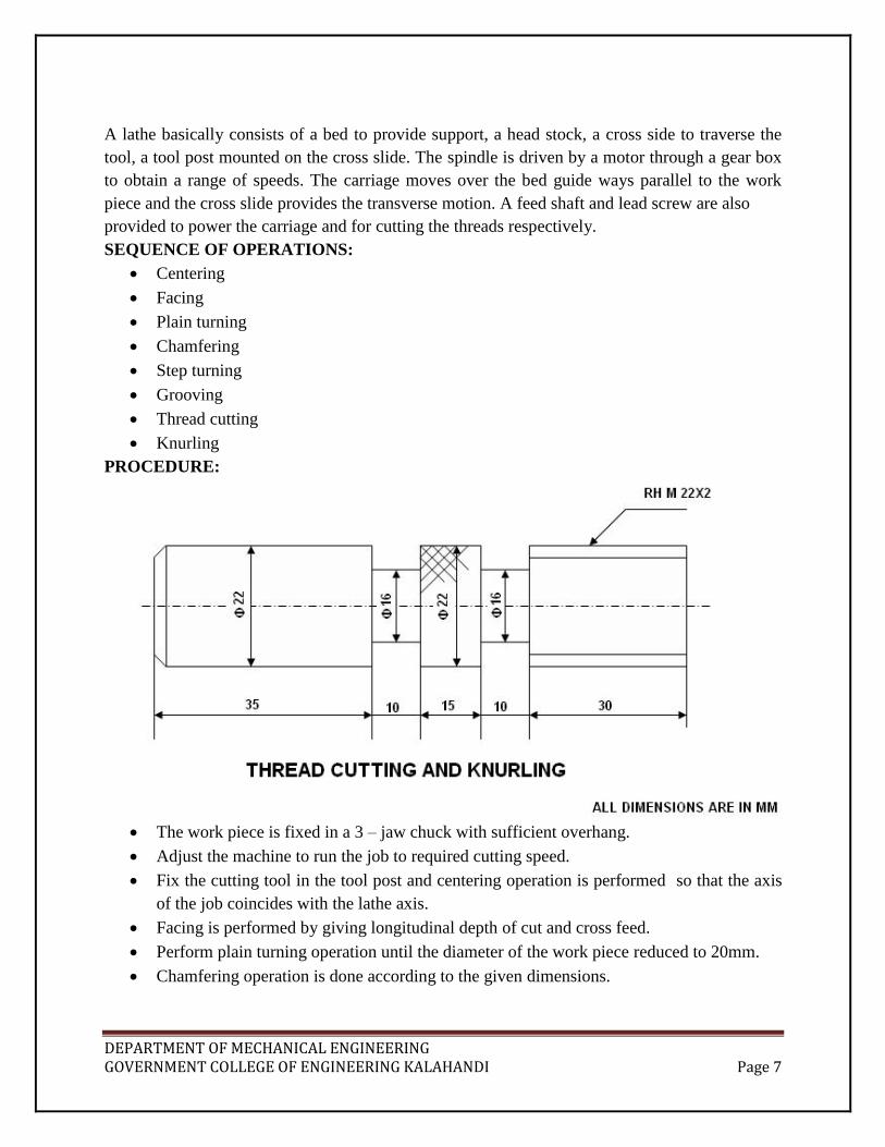
The work piece is fixed in a 3 – jaw chuck with sufficient overhang.
Adjust the machine to run the job to required cutting speed.
Fix the cutting tool in the tool post and centering operation is performed so that the axis
of the job coincides with the lathe axis.
Facing is performed by giving longitudinal depth of cut and cross feed.
Perform plain turning operation until the diameter of the work piece reduced to 20mm.
Chamfering operation is done according to the given dimensions.

DEPARTMENT OF MECHANICAL ENGINEERING GOVERNMENT COLLEGE OF ENGINEERING KALAHANDI Page 8
Then reverse the work piece in the chuck and plain turning operation is performed
according to the given dimensions.
Using V-cutting tool and parting off tool perform grooving operation to the required
dimensions.
Reduce speed of the spindle by engaging back gear and use Tumbler
feed reversing mechanism to transmit power through the lead screw.
And calculate the change gears for the required pitch to be made on the work piece.
Using half nut mechanism perform thread cutting operation(right hand threading)
according to the given dimensions and continues it until required depth of cut is obtained.
At the same speed knurling operation is performed using knurling tool.
For every operation check the dimensions using vernier calipers.
PRECAUTIONS:
Before starting the spindle by power, lathe spindle should be revolved by one revolution
by hand to make it sure that no fouling is there.
Tool should be properly ground, fixed at correct height and properly secured, and work
also be firmly secured.
Chips should not be allowed to wind around a revolving job and cleared as often as
possible.
Before operating threading operation, V-tool should be properly ground to the required
helix angle.
Apply cutting fluids to the tool and work piece property.
No attempt should be made to clean the revolving job with cotton waste.
On hearing unusual noise, machine should be stopped.
RESULT: The job is completed successfully and safely.

DEPARTMENT OF MECHANICAL ENGINEERING GOVERNMENT COLLEGE OF ENGINEERING KALAHANDI Page 9
SPUR GEAR CUTTING IN MILLING MACHINE
Experiment No-02 Aim: To produce a spur gear out of the given work piece using milling machine
Apparatus Required:
Horizontal Milling machine
M10 – End Mill Cutter ( HSS )
Gear tooth Vernier
Materials Required:
Cast Iron Work piece – 55mm diameter, 20mm thickness
Milling Machine
DEPARTMENT OF MECHANICAL ENGINEERING GOVERNMENT COLLEGE OF ENGINEERING KALAHANDI Page 10
Procedure:
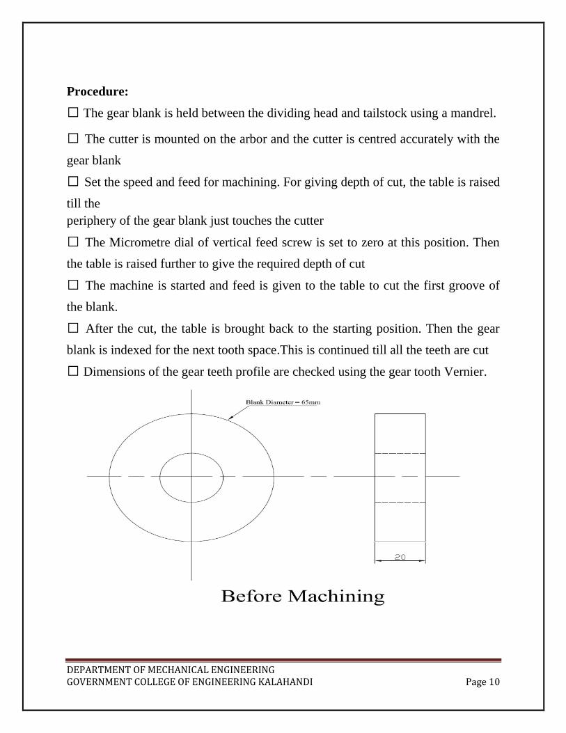
The gear blank is held between the dividing head and tailstock using a mandrel.
The cutter is mounted on the arbor and the cutter is centred accurately with the
gear blank
Set the speed and feed for machining. For giving depth of cut, the table is raised
till the
periphery of the gear blank just touches the cutter
The Micrometre dial of vertical feed screw is set to zero at this position. Then
the table is raised further to give the required depth of cut
The machine is started and feed is given to the table to cut the first groove of
the blank.
After the cut, the table is brought back to the starting position. Then the gear
blank is indexed for the next tooth space.This is continued till all the teeth are cut
Dimensions of the gear teeth profile are checked using the gear tooth Vernier.

DEPARTMENT OF MECHANICAL ENGINEERING GOVERNMENT COLLEGE OF ENGINEERING KALAHANDI Page 11
After Machining
Calculation:
Pitch circle Diameter DP = Diameter of the Blank(D) – ( 2 X Module(m)) =
65-(2X2.5)=60
Number of teeth Z = Pitch circle Diameter / module = 60 / 2.5 = 24
Circular Pitch PC = πDP / Z
The relationship between normal pitch and transverse pitch is given by
PN = PC X cosα
Helical Gear considerations:
Helix Angle α is related to Pitch circle diameter (DP) and the lead of the helix
(L) by the following relation
Tan α = πDP / L
With any of the two known values, the third value can be found
Indexing Calculation: Indexing = 40 / Z
Result: Thus a spur gear is made from the given work piece using milling
machine.

DEPARTMENT OF MECHANICAL ENGINEERING GOVERNMENT COLLEGE OF ENGINEERING KALAHANDI Page 12
HELICAL GEAR CUTTING IN MILLING MACHINE
Aim: To cut a helical gear out of the given blank in milling machine
Apparatus Required:
Horizontal Milling machine
M10 – End Milling cutter
Materials Required: Cast Iron Blank – 65mm diameter and 20mm thickness
Procedure:
The M10 milling cutter is set on the mandrel
The table is swivelled to an inclination of α ( Helix Angle ) with the axis of
work piece
The required gear ratio is set between the work table and the mandrel holding
the work
piece so that movement of the work table rotates the work piece through the proper
helix
angle progressively
The spindle is switched on and the required depth of cut is set before the tool
cuts the work
piece.
Single teeth cavity is cut through the work piece.
After Indexing the next tooth is cut in similar fashion and so on
The gear tooth dimensions are checked using a gear tooth Vernier.
Result: Thus a helical gear is cut out of the given blank using horizontal milling
machine.

DEPARTMENT OF MECHANICAL ENGINEERING GOVERNMENT COLLEGE OF ENGINEERING KALAHANDI Page 13
GEAR SHAPER MACHINE
Experiment No-03 STUDY:
This process uses a pinion shaped cutter carrying clearance on the tooth face
and sides and a hole at its centre for mounting it on a stub arbor or spindle of the
machine
The cutter is mounted by keeping its axis in vertical position
It is made to reciprocate up and down along the vertical axis up to a pre decided
amplitude
Both the cutter and the gear blank are set to rotate at a very low RPM about
their axis
The relative rpm of both (cutter and blank) can be fixed to any of the available
value with the help of a gear train.
This way all the cutting teeth of cutter come is action one-by-one giving
sufficient time for their cooling and incorporating a longer tool life
The principle of gear cutting by this process as explained above is depicted in
the Figure below

DEPARTMENT OF MECHANICAL ENGINEERING GOVERNMENT COLLEGE OF ENGINEERING KALAHANDI Page 14
The main parameters to be controlled in the process are described below
Cutting Speed:
Shaper cutter can move vertically upward and downward during the operation.
The downward movement of the cutter is the cutting stroke and its speed
(linear) with which it comes down is the cutting speed.
Length of cutting stroke can be adjusted to any value out of available values on
the machine

DEPARTMENT OF MECHANICAL ENGINEERING GOVERNMENT COLLEGE OF ENGINEERING KALAHANDI Page 15
Indexing motion:
Indexing motion is equivalent to feed motion in the gear shaping operation.
Slow rotations of the gear cutter and work piece provide the circular feed to the
operation.
These two rpms are adjusted with the help of a gear train
Depth Of Cut:
The required depth is maintained gradually by cutting the teeth into two or three
pass
In each successive pass, the depth of cut is increased as compared to its
previous path
This gradual increase in depth of cut takes place by increasing the value of
linear feed in return stroke.
A Schematic representation of gear shaper is shown above with various parts
The main advantage of gear shaper is that the process can be used to make a
variety of gears and the cycle time for producing one work piece is very less
compared to many other processes. Close
tolerances can be maintained

DEPARTMENT OF MECHANICAL ENGINEERING GOVERNMENT COLLEGE OF ENGINEERING KALAHANDI Page 16
The main disadvantage is that there is no cutting in the return stroke. The
process cannot be used to manufacture worm and worm wheel, which is a special
type of gear.

DEPARTMENT OF MECHANICAL ENGINEERING GOVERNMENT COLLEGE OF ENGINEERING KALAHANDI Page 17
SPUR GEAR CUTING IN GEAR SHAPER MACHINE
Aim: To machine the given gear blank into a spur gear in gear shaper machine
Apparatus Required:
Gear Shaper Machine
Shaper cutter
Material required:
Cast iron blank
Procedure:
The given gear blank is mounted on the work piece spindle
The shaper cutter having the necessary cutting teeth in the shape if tooth
spacing of the required work piece is mounted on the cutter spindle
Necessary gear ratio is set between the work piece spindle and the cutter spindle
for the purpose of indexing
Machine is switched on and shaping process of the tooth spacing of the gear
profile is done with the shaper cutter, in two to four passes per teeth. This feed
motion is given during the return stroke
With the indexing done through a gear train, the cutter gradually rotates and the
work piece rotates in accordance with the cutter, as if they are two gears in mesh
With one complete revolution of the work piece on its spindle the gear shaping
process will be complete
The dimensions of the gear teeth are checked using a gear tooth Vernier
Result: Thus the required spur gear is cut from the given blank by gear shaping
process.

DEPARTMENT OF MECHANICAL ENGINEERING GOVERNMENT COLLEGE OF ENGINEERING KALAHANDI Page 18
PLANING MACHINE
INTRODUCTION
Planing is one of the basic operations performed in machining work and is primarily intended for
machining large flat surfaces. These surfaces may be horizontal, vertical or inclined. In this way,
the function of a planning machine is quite similar to that of a shaper except that the former is
basically designed to undertake machining of such large and heavy jobs which are almost
impractical to be machined on a shaper or milling, etc. It is an established fact that the planning
machine proves to be most economical so far as the machining of large flat surfaces is
concerned. However, a palning machine differs from a shaper in that for machining, the work,
loaded on the table, reciprocates past the stationary tool in a planer, whereas in a shaper the tool
reciprocates past the stationary work.
WORKING PRINCIPLE OF A PLANER:
The principle involved in machining a job on a planer is illustrated in fig. Here, it is almost a
reverse case to that of a shaper. The work is rigidly held on the work table or a platen of the
machine. The tool is held vertically in the toolhead mounted on the cross rail. The work table,
together with the job, is made to reciprocate past the vertically held tool. The indexed feed after
each cut is given to the tool during the idle stroke of the table.
SPECIFICATIONS:
Horizontal distance between two vertical housings:
Vertical distance between table top and the cross rail: 800mm
Maximum length of table travel: 1350mm
Length of bed: 2025mm
Length of table: 1425mm
Method of driving – Individual
Method driving table – Geared
H.P. of motor: 3 H.P. & 1 H.P.

DEPARTMENT OF MECHANICAL ENGINEERING GOVERNMENT COLLEGE OF ENGINEERING KALAHANDI Page 19
STANDARD OR DOUBLE HOUSING PLANER:
This is the most commonly used type of planer. It consists of two vertical housings or columns,
one on each side of the bed. The housings carry vertical or scraped ways. The cross-rail is fitted
between the two housings and carries one or two tool heads. The work table is mounted over the
bed. Some planers may fit with side tool heads fitted on the vertical columns.
MAIN PARTS OF A PLANER
A planer consists of the following main parts as illustrated by means of a block diagram in fig.
Bed
Table
Housings or columns
Cross – rail
Tool head
Controls
These machines are heavy duty type and carry a very rigid construction. They employ high
speeds for cutting but the size of work they can handle is limited to the width of their table i.e.
the horizontal distance between the columns.

DEPARTMENT OF MECHANICAL ENGINEERING GOVERNMENT COLLEGE OF ENGINEERING KALAHANDI Page 20
Extremely large and heavy castings, like machine beds, tables, plates, slides, columns, etc.,
which normally carry sliding surfaces like guide ways or dovetails on their longitudinal faces,
are usually machined on these machines. Also because of long table and larger table travel, on
either side of the columns, it is possible to hold a number of work pieces in a series over the bed
length and machine them together. This will effect a substantial saving in machining time.
Further because of no.of tool heads the surfaces can be machined simultaneously. This effects
further reduction in machining time. Also because of high rigidity of high rigidity of the machine

DEPARTMENT OF MECHANICAL ENGINEERING GOVERNMENT COLLEGE OF ENGINEERING KALAHANDI Page 21
and robust design of the cutting tools heavier cuts can be easily employed, which leads to
quicker metal removal and reduced machining time. Thus an overall picture emerges that the
employment of this type of machine apart from its capacity to handle such heavy and large jobs
which are difficult to be handled on other machines, leads to faster machining and reduced
machining time and hence to economical machining. However considerable time is used in
setting up a planer.
DRIVE MECHANISMS:
Four different methods are employed for driving the table of a planer. They are:
Crank drive
Belt drive
Direct reversible drive
Hydraulic drive

DEPARTMENT OF MECHANICAL ENGINEERING GOVERNMENT COLLEGE OF ENGINEERING KALAHANDI Page 22
SLOTTING
AIM:
To Make internal splines, space 900 apart on the given hollow cylindrical work
piece by using slotting machine.
REQUIRED MATERIAL:
M.S. Hollow Cylindrical work piece of 65 mm diameter and 70 mm length
REQUIRED TOOLS:
H.S.S. Cutting tool, Adjustable wrench, Scriber
SPECIFICATION OF THE MACHINE:
Stroke 150 mm
Rotary table 275 mm
Longitudinal Movement 200 mm
Cross Movement 200 mm
Power of the motor 1 h.p.
THEORY:
A Slotting machine or slotter has its won importance for a few particular classes of work. Its
main use is in cutting different types of slots and it certainly proves to be most economical so far
as this kind of work is concerned. Its other uses are in machining irregular shapes, circular
surfaces and other premarked profiles, both internal as well as external. Its construction is similar
to that of vertical shaper. Its ram moves vertically and the tool cuts during the downward stroke
only.
Main Parts of a Slotter:
Base: It is heavy cast iron construction and is also known as bed. It acts as support for the
column, the driving mechanism, ram, table and all other fittings. At its top it carries horizontal
ways, along which the table can be traversed.

DEPARTMENT OF MECHANICAL ENGINEERING GOVERNMENT COLLEGE OF ENGINEERING KALAHANDI Page 23
Column: It is another heavy cast iron body which acts as a housing for the driving mechanism.
At its front carries vertical ways, along which the ram moves up and down.
Table: Usually a circular table is provided on slotting machines. In some heavy duty slotters,
either rectangular or circular table can be mounted. On the top of table are provided T- slots to
clamp the work or facilitate the use of fixtures etc.
Ram: It moves in vertical direction on the guide ways provided in front of the column. At its
bottom, it carries the tool post in which the tool is held. The cutting action takes place during the
downward movement of the ram.

DEPARTMENT OF MECHANICAL ENGINEERING GOVERNMENT COLLEGE OF ENGINEERING KALAHANDI Page 24
PROCEDURE:
The tool is fixed to the tool post such that the movement should be exactly perpendicular
to the table.
The work piece is then set in the vice such that the tool is just above the work piece.
Adjust the length of the stroke of the ram.
Slotting operation is performed and make one slot on the work piece to the
required dimensions.

DEPARTMENT OF MECHANICAL ENGINEERING GOVERNMENT COLLEGE OF ENGINEERING KALAHANDI Page 25
Then bring the tool to the initial position
Rotate the work table by an angle 900 and continue the process for the
second slot.
Repeat the process for the remaining slots.
PRECAUTIONS:
The work piece should be set securely and rigidly in the vice.
Before starting the machine make sure that the work, vice, tool, and ram
are securely fastened.
Check that the tool and tool holder will clear the work and also clear the
column on the return stroke.
Make sure that the axis of the work piece is parallel to the line of action of
tool.
Never attempt to adjust a machine while it is in motion.
Suitable feeds and depth of cut should be maintained uniformly.
Always feed will be given to the work in the backward stroke only.
RESULT: The job is completed successfully and safely.

DEPARTMENT OF MECHANICAL ENGINEERING GOVERNMENT COLLEGE OF ENGINEERING KALAHANDI Page 26
SURFACE GRINDING
Experiment No-04 INTRODUCTION:
It consists of the main driving motor situated over the housings. This motor drives the
countershaft through an open V- belt. The countershaft, at its extreme carries two driving
pulleys; one for open belt and the other for cross belt. The main driving shaft is provided below
the bed. One end of it passes through the housing and carries a pinion, which meshes with the
rack provided under the table of the machine as shown. The other end of this shaft carries two
pairs of pulleys – each pair consisting of a fast pulley and loose pulley. One of these pairs is
connected to one of the driving pulleys by means of a open belt and the other to the second
driving pulley by means of a cross belt. A speed reduction gear box is mounted on the main
driving shaft and the same is incorporated between the pinion and the pairs of driven pulleys.
One set of the above pulleys is used for the forward motion of the table and the other set for
backward or return motion. the cross belt will be used for forward motion and the open belt for
return motion. Note that the driving pulley on the counter shaft for cross belt is smaller than the
pair of fast and loose pulleys for the same. Against this the driving pulley on the countershaft for
open belt is bigger than the pair of fast and loose pulleys for the same. Consequently therefore
for the same speed or number of revolutions of the countershaft the main driving shaft will run
faster when connected by open belt than when the cross belt is used. It is obvious therefore that
the return stroke will be faster than the forward stroke. It should also be noted here that the
pulleys are so arranged that when the cross belt is on the fast pulley, i.e. in forward stroke the
open belt will be on the loose pulley and its reverse will take place during the return stroke. In
order that this relative shifting of belt may take place automatically at the end of each stroke,
without stopping the machine, a belt shifter and its operating lever are provided on the machine.
Trip dogs are mounted one each at both ends, on the table. At the end of each stroke these dogs
strike against the operating lever alternately and the belt shifted accordingly. Thus the table
movement is reversed automatically.
OPERATION DONE ON A PLANER:
The common operations performed on a planer include the following:
Machining horizontal flat surfaces.
Machining vertical flat surfaces.
Machining angular surfaces, including dovetails.
Machining different types of slots and grooves.
Machining curved surfaces.
Machining along premarked contours.

DEPARTMENT OF MECHANICAL ENGINEERING GOVERNMENT COLLEGE OF ENGINEERING KALAHANDI Page 27
PLAIN SURFACE GRINDING
Aim: To perform plain surface grinding on the given work piece to the required
dimensions
Apparatus required:
Grinding machine
Grinding Wheel
Vernier Calliper
Material Required:
MS / CI plate 12mm X 50mm X 75mm

DEPARTMENT OF MECHANICAL ENGINEERING GOVERNMENT COLLEGE OF ENGINEERING KALAHANDI Page 28
Procedure:
First the work piece is placed on the magnetic chuck
The positioning of the work piece is aligned at right angles to the grinding
wheel and exactly parallel to the sides of the magnetic chuck by using slip gauges
if necessary
The magnetic chuck is switched on and the powerful electromagnet holds the
job firmly in position
Now the spindle is turned on and the grinding wheel is just touched the work
piece surface to mark its zero / reference position
Now the required feed, either totally or in steps, is given to the grinding wheel
and the wheel is traversed all over the work piece
Same procedure is repeated until the required dimensions are achieved
Care should be taken for maintaining the surface finish
Finally the dimensions are checked using either a Vernier calliper or a screw
gauge.
Result: Thus plain surface grinding is performed on the given work piece up to the
required Dimensions.

DEPARTMENT OF MECHANICAL ENGINEERING GOVERNMENT COLLEGE OF ENGINEERING KALAHANDI Page 29
CYLINDRICAL GRINDING
Aim: To grind the cylindrical surface of the given work piece by cylindrical
grinding
Apparatus Required:
Grinding machine
Cylindrical grinding wheel setup
Steel Rule
Vernier Calliper
Materials Required:
Cast iron work piece

DEPARTMENT OF MECHANICAL ENGINEERING GOVERNMENT COLLEGE OF ENGINEERING KALAHANDI Page 30
Procedure:
First the given work piece is preliminarily finished to the pre-required
dimensions on a lathe before beginning the grinding process
Now the work piece is fitted in the chuck of the cylindrical grinding machine
The grinding wheel is just touched with the work piece and is taken as the zero
reference
Coolant circulation is switched on and the grinding wheel is engaged with the
work piece.
Both the work piece and the grinding wheel roll on contact with each other like
two gears in mesh
Now slowly the wheel is moved over the entire length of the work piece to get
the grinded finish
After one feed is over, the grinding wheel is moved further towards the axis of
the work piece and the process is repeated until the required dimensions are
achieved
Finally the dimensions are checked using a Vernier calliper
Result: Thus cylindrical grinding is performed on the given work piece to the
given dimensions.

DEPARTMENT OF MECHANICAL ENGINEERING GOVERNMENT COLLEGE OF ENGINEERING KALAHANDI Page 31
TOOL DYNAMOMETERS
Experiment No-05 AIM:
To study the Lathe Tool Dynamometer and Drill Tool Dynamometer and determine the
Resultant force act on the tool during turning operation and also estimate the force and thrust
required to perform drilling operation.
APPARATUS REQUIRED:
Lathe tool Dynamometer and Drill tool dynamometer.
TOOLS & MATERIAL REQUIRED:
HSS tool with tool holder, Φ25mm MS bar, and 10mm thick MS flat and 10mm drill.
THEORY:
In machining or metal cutting operation the device used for determination of cutting forces is
known as a Tool Dynamometer or Force Dynamometer. Majority of dynamometers used for
measuring the tool forces use the deflections or strains caused in the components, supporting the
tool in metal cutting, as the basis for determining these forces. In order that a dynamometer gives
satisfactory results it should possess the following important characteristics:
It should be sufficiently rigid to prevent vibrations.
At the same time it should be sensitive enough to record deflections and strains
appreciably.
Its design should be such that it can be assembled and disassembled easily.
A simpler design is always preferable because it can be used easily.
It should possess substantial stability against variations in time, temperature, humidity
etc.
It should be perfectly reliable.
The metal cutting process should not be disturbed by it, i.e. no obstruction should be
provided by it in the path of chip flow or tool travel.
Types of Dynamometers:
Irrespective of their design and the technique used for strain measurement, most of the force
dynamometers used today carry a measuring system which is precalibrated for its stiffness. The
cutting forces are measured by these dynamometers by measuring the strain or deflection caused
in this system due to the force under measurement. The different types of commonly used
dynamometers can be broadly classified as:
Mechanical dynamometers
Strain Gauge type dynamometers
Pneumatic and Hydraulic dynamometers
Electrical Dynamometers
Piezoelectric dynamometers
DEPARTMENT OF MECHANICAL ENGINEERING GOVERNMENT COLLEGE OF ENGINEERING KALAHANDI Page 32
Tool Dynamoeters
PROCEDURE:
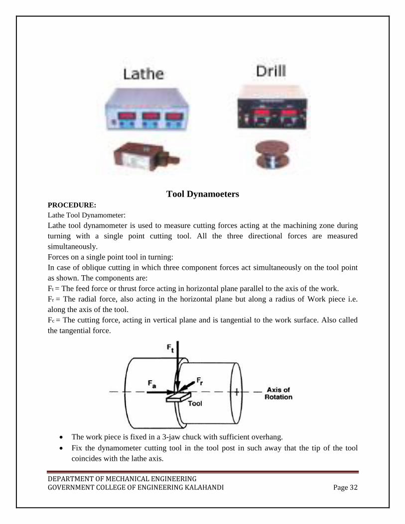
Lathe Tool Dynamometer:
Lathe tool dynamometer is used to measure cutting forces acting at the machining zone during
turning with a single point cutting tool. All the three directional forces are measured
simultaneously.
Forces on a single point tool in turning:
In case of oblique cutting in which three component forces act simultaneously on the tool point
as shown. The components are:
Ft = The feed force or thrust force acting in horizontal plane parallel to the axis of the work.
Fr = The radial force, also acting in the horizontal plane but along a radius of Work piece i.e.
along the axis of the tool.
Fc = The cutting force, acting in vertical plane and is tangential to the work surface. Also called
the tangential force.
The work piece is fixed in a 3-jaw chuck with sufficient overhang.
Fix the dynamometer cutting tool in the tool post in such away that the tip of the tool
coincides with the lathe axis.

DEPARTMENT OF MECHANICAL ENGINEERING GOVERNMENT COLLEGE OF ENGINEERING KALAHANDI Page 33
Select proper cutting speed, feed and depth of cut.
Perform turning operation on the work.
Directly measure the three components of forces acting on the tool using
lathe tool dynamometer.
Repeat the procedure for varying the above three parameters (CS, F & DC).
The resultant force can be calculated by
222
rtc FFFR
Observe the effect of cutting speed, feed and depth of cut on force.
Drill Tool Dynamometer:
This is strain gauge Drill Tool Dynamometer designed to measure thrust and torque during
drilling operation. This dynamometer is suitable for drilling a hole up to 25mm size in Mild
Steel. Drilling tool dynamometer is a Rigid in construction, Compact Unit, Easy in handling and
Assessment of cutting forces by giving due consideration to various parameters like depth of cut,
material, speed and feed.
Force system in drilling:
During the process of drilling a lot of axial pressure (Thrust force) is applied on it in order to
make it penetrate into the material. On account of this pressure all the drill elements are
subjected to one or other type of force.

DEPARTMENT OF MECHANICAL ENGINEERING GOVERNMENT COLLEGE OF ENGINEERING KALAHANDI Page 34
The principal forces are:
FH – An equal and opposite horizontal force acting on both lips of the drill and thus neutralizing
each other.
Fv - Vertical force acting at the centre of the drill in a direction opposite to that of the applied
pressure.
Fv1 - Vertical force acting in the same direction as F , on the lips of the drill it is the main cutting
force in the operation.
Ff1 - Frictional force due to rubbing of upward flowing chips against wall of the hole and flutes
of the drill.
F f2 - frictional force due to rubbing between the drill margin and the hole surface.
P – The applied axial pressure or thrust force acting along the axis of drill to press it into the
work piece material.
In order that the drill penetrates into the work piece the applied pressure P, should be able to
overcome all the resistive forces acting against it.
P > (FV + 2FV1 + Ff1 + Ff2)
It is reckoned that as compared to FV and FV1 the magnitudes of the frictional forces Ff1 and Ff2
are too small to be considered for practical purposes. Hence they are considered negligible.
Therefore P = FV + 2FV1
Thrust force acting on the drill, M = C d1.9
f0.8
N-mm
Where d is the diameter of the drill in mm
f is the feed per revolution, mm/rev
C is a constant depends upon the material to be machined
For Steel, C = 616
Aluminium alloys, C = 180
Magnesium alloys, C = 103
Brasses, C = 359
Torque acting on the drill is given by T = K d f0.7
N
For Steel, K = 84.7
Cast Iron = 60.5
Fix the drill of a particular diameter in the drill chuck.
Fix the work piece in vice mounted on the bed of the machine.
Attach the drill tool dynamometer to the machine.
Perform drilling operation on the work.
Note down the values of thrust force and torque acting on the drill directly from drill tool
dynamometer.
Repeat the procedure by varying the speed, feed and depth of cut of the drill.
Observe how these parameters will effects the force and torque.
PRECAUTIONS:
The tool should be rigidly mounted on the lathe tool post.

DEPARTMENT OF MECHANICAL ENGINEERING GOVERNMENT COLLEGE OF ENGINEERING KALAHANDI Page 35
Make sure that there should not be any vibrations in the tool.
Readings should be noted carefully.
Select the cutting speed, feed and depth of cut properly.
RESULT: The job is completed successfully and safely.

DEPARTMENT OF MECHANICAL ENGINEERING GOVERNMENT COLLEGE OF ENGINEERING KALAHANDI Page 36
UNCONVENTIONAL MACHINING PROCESSES
Experiment No-06 INTRODUCTION:
New machining methods have been developed mainly because of the difficulties in machining
hard, high-strength, and temperature-sensitive materials. These processes have been used for
removing excess materials from the work piece to obtain the desired shape and size and have
come to be known as unconventional machining processes. Table 1 lists these processes and
indicates the types of energies and methods of material removal.
Table 1 Unconventional machining processes

DEPARTMENT OF MECHANICAL ENGINEERING GOVERNMENT COLLEGE OF ENGINEERING KALAHANDI Page 37
Electro-chemical Machining
The electrochemical machining process is illustrated in above Fig. The workpiece (Which must
be a conductor of electricity) is placed in a tank on the machine table and connected to the
positive terminal of a dc supply. The tool electrode, shaped to form the required cavity in the
workpiece, is mounted in the tool holder and connected to the negative terminal of the supply.
An electrolyte flows through the gap between the tool and the work piece and is then pumped
back to the working zone; either through the tool or externally, depending on the application.
The action of the current flowing through the electrolyte is to dissolve the metal at the anode,
i.e., the workpiece. The electrical resistance is lowest (and hence the current is highest) in the
region where the tool and workpiece are closest. Since the metal is dissolved from the workpiece
most rapidly in this region, the form of the tool will be reproduced on the workpiece.
There is no mechanical contact between the workpiece and the tool, and any tendency of the
workpiece metal to be plated on the tool is counteracted by the flow of the electrolyte, which
removes the dissolved metal from the working zone. Hence there is neither tool wear nor plating
of the workpiece material on the tool so that one tool can produce a large number of components
during its life. The voltage and current are constant in the electrochemical machining process.
SUMMARY OF ECM CHARACTERISTICS
Mechanics of material removal : Electrolysis
Medium : Conducting ectrolyte
Tool Materials : Cu, brass, steel
Gap : 50-300 μm
Maximum material removal rate: 15x 103
mm3
/min
Specific power consumption (typical) :7 W/mm3
/min
Critical parameters: Voltage, current, feed rate, electrolyte, and electrolyte conductivity
Material application: All conducting metals and alloys

DEPARTMENT OF MECHANICAL ENGINEERING GOVERNMENT COLLEGE OF ENGINEERING KALAHANDI Page 38
Shape application: Blind complex cavities, curved surfaces, through cutting, large through
cavities
Limitations: High specific energy consumption (about 150 times that required for conventional
processes), not applicable with electrically non-conducting materials and for jobs with very small
dimensions, expensive machine.

DEPARTMENT OF MECHANICAL ENGINEERING GOVERNMENT COLLEGE OF ENGINEERING KALAHANDI Page 39
ELECTRIC DISCHARGE MACHINING (EDM)
Electric-discharge machining (EDM), or spark machining, as it is also called, is based on the
eroding effect of an electric spark on both the electrodes used to produce it. It has been found
from observation that if both electrodes are made of the same material, greater erosion occurs on
the positive electrode. Hence, to obtain maximum metal removal with minimum wear on the
tool' electrode; the work is made the positive and the tool the negative electrode. The principle of
the electric-discharge machining process is illustrated by the simplified diagram in Fig. 4. The
tool is mounted on the chuck attached to the machine spindle whose vertical feed is controlled by
the servomotor through a reduction gearbox; The workpiece is placed in a tank filled with a
dielectric fluid; a depth of at least 50mm over the work surface is maintained to eliminate the
risk of fire: The tool and work piece are connected to a dc relaxation circuit fed either from a dc
generator, or more commonly, a mercury-arc or selenium-type rectifier. Dielectric fluid is
circulated under pressure by a pump, usually through a hole (or holes) in the tool electrode. A
spark gap of about 10-125 μm is maintained by the servomotor.
When the power supply is switched on, the condenser voltage Vc begins to increase
exponentially toward the supply voltage Vs and no current flows. As the voltage Vc builds, it
reaches the gap breakdown voltage Vg (determined by the gap width and the dielectric fluid); a
spark is produced across the gap, the dielectric fluid ionizes and the condenser is discharged. The
surrounding dielectric then deionizes so that it again becomes an effective insulator, and the

DEPARTMENT OF MECHANICAL ENGINEERING GOVERNMENT COLLEGE OF ENGINEERING KALAHANDI Page 40
cycle is repeated. In this way a rapid succession of sparks is obtained, the interval between
successive sparks being of the order of 100μs.
Each spark generates a localized high temperature of the order of 12000oC in its immediate
vicinity. This heat causes part of the surrounding dielectric fluid to evaporate; it "also melts and
vaporizes the metal to form a small crater on the work surface. Since the spark always occurs
between the points of the tool and work that are close together, the high spots of the work are
gradually eroded, and the form of the tool is reproduced on the work. The condensed metal
globules, formed during the process, are carried away by the flowing dielectric fluid. As the
metal is eroded, the tool is fed in by a servo controlled feed mechanism.
SUMMARY OF EDM CHARACTERISTICS
Mechanics of material removal Melting and evaporation aided by cavitations
Medium Dielectric fluid
Tool Materials Cu, brass, Cu-W alloy, graphite
Maximum material removal rate 5x103 mm3/min
Specific power consumption (typical) 1.8 W/mm3/min
Critical Material application All conducting metals and alloys
Shape application Blind complex cavities, micro holes for nozzles, through cutting of non-
circular holes, narrow slots.
Limitations : High specific energy consumption (about 150 times that in conventional
machining); when forced circulation of dielectric is not possible, removal rate is quite low;
surface tends to be rough for larger removal rates not applicable to nonconducting materials.