made in taiwan user’s guide - br.omega.com · meteruse the only as specified in this manual;...
TRANSCRIPT
omega.com e-mail: [email protected]
For latest product manuals:omegamanual.info
Shop online at
Made in Taiwan User’s GuideDATALOGGER 4 INPUT
THERMOMETER
HH1384
INSTRUCTION MANUAL
MAX MIN
ALARM
-
INTVm:sd-h
FULLNO.
T 4T 3
T 2T 1

1. INTRODUCTION: FEATURES This instrument is a digital 4 input thermometer and data logger that works with any K, J, E, T, R, S, N, L, U, B and C-type thermocouple temperature sensor. Temperature indication follows the international temperature scale of 1990 (ITS-90).
Read the following safety information carefully before attempting to operate the meter. Use the meter only as specified in this manual; otherwise, the protection provided by the meter may be impaired.
Environment conditions Altitude up to 2000 meters Relatively humidity 80% max. Operation Ambient 0~50°C(32°F ~122°F)
Features Isolated Input Protection of 350Vp-p between any two inputs. Highly accurate thermometer with thermocouple K, J, E, T, R, S, N, L, U, B, C types.
4 input function T1/T2/T3/T4 temperature display. Programmable Hi – Lo alarm for 4 inputs. Display of MAX, MIN and MAX–MIN values of 4 inputs. Independent Input Setup (type of thermocouple, Hi – Lo alarm values).
Memory and Read function (99 sets) 512KB auto datalogging capacity. USB interface.
Safety symbols
Comply with EMC
~ 1 ~
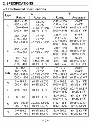
2. SPECIFICATIONS 2-1 Electronical Specifications
°C °FTypeRange Accuracy Range Accuracy
K-200 ~ -150-150 ~ -100-100 ~ 999.91000 ~ 1370
±3.0°C±2.0°C
±0.05% ±1.0°C±0.2% ±1.0°C
-328 ~ -238 -238 ~ -148 -148 ~ 999.9 1000 ~ 2498
±5.4°F±3.6°F
±0.05% ±1.8°F±0.2% ±1.8°F
J-200 ~ -100-100 ~ 100100 ~ 999.9
±2.5°C±1.5°C
±0.05% ±1.0°C
-328 ~ -148 -148 ~ 212 212 ~ 999.9 1000 ~ 1832
±4.5°F±2.7°F
±0.05% ±1.8°F±0.2% ±1°F
E -150 ~ -100-100 ~ 760
±3.0°C±0.05% ±1.0°C
-238 ~ -148 -148 ~ 999.9 1000 ~ 1400
±5.4°F±0.05% ±1.8°F
±0.2% ±1°F
T-200 ~ -150-150 ~ -100-100 ~ 400
±3.0°C±0.15% ±2.5°C±0.1% ±1.0°C
-328 ~ -238 -238 ~ -148 -148 ~ 752
±5.4°F±0.15% ±4.5°F±0.1% ±1.8°F
R/S0 ~ 100
100 ~ 300300 ~ 999.91000 ~ 1600
±5.0°C±3.0°C
±0.05% ±2.0°C±0.25% ±2.0°C
32 ~ 212 212 ~ 572
572 ~ 999.9 1000 ~ 2912
±9.0°F±5.4°F
±0.05% ±3.6°F±0.25% ±3.6°F
N 0 ~ 999.9 1000 ~ 1300
±0.1% ±1.0°C±0.2% ±1.0°C
32 ~ 999.9 1000 ~ 2372
±0.1% ±1.8°F±0.2% ±1.8°F
L -200 ~ 900 ±0.1% ±1.0°C -328 ~ 999.9 1000 ~ 1652
±0.1 % ±1.8°F±0.2% ±1°F
U 0 ~ 600 ±0.1% ±1.0°C 32 ~ 999.9 1000 ~ 1112
±0.1% ±1.8°F±0.2% ±1°F
B 600 ~ 999.91000 ~ 1760
±0.05% ±2.0°C±0.1% ±2.0°C
1112 ~ 1831 1832 ~ 3200
±0.05% ±3.6°F±0.1% ±3.6°F
C 0 ~ 999.9 1000 ~ 1760
±0.1% ±1.5°C±0.2% ±1.5°C
32 ~ 999.9 1000 ~ 3200
±0.1% ±2.7°F±0.2% ±2.7°F
~ 2 ~
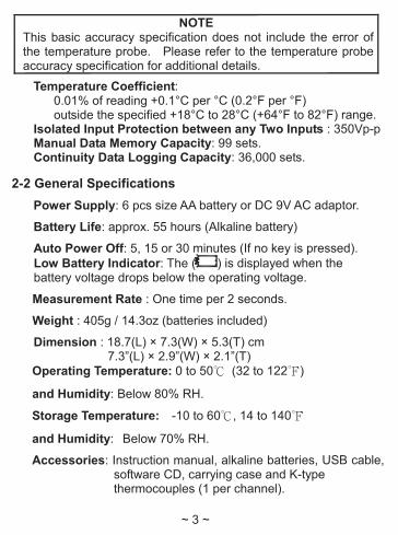
NOTE This basic accuracy specification does not include the error of the temperature probe. Please refer to the temperature probe accuracy specification for additional details.
Temperature Coefficient:0.01% of reading +0.1°C per °C (0.2°F per °F) outside the specified +18°C to 28°C (+64°F to 82°F) range.
Isolated Input Protection between any Two Inputs : 350Vp-p Manual Data Memory Capacity: 99 sets. Continuity Data Logging Capacity: 36,000 sets.
2-2 General Specifications Power Supply: 6 pcs size AA battery or DC 9V AC adaptor.
Battery Life: approx. 55 hours (Alkaline battery)
Auto Power Off: 5, 15 or 30 minutes (If no key is pressed). Low Battery Indicator: The ( ) is displayed when the battery voltage drops below the operating voltage.
Measurement Rate : One time per 2 seconds.
Weight : 405g / 14.3oz (batteries included)
Dimension : 18.7(L) × 7.3(W) × 5.3(T) cm 7.3”(L) × 2.9”(W) × 2.1”(T)
Operating Temperature: 0 to 50℃ (32 to 122℉)
and Humidity: Below 80% RH.
Storage Temperature: -10 to 60℃, 14 to 140℉
and Humidity: Below 70% RH.
Accessories: Instruction manual, alkaline batteries, USB cable, software CD, carrying case and K-type thermocouples (1 per channel).
~ 3 ~
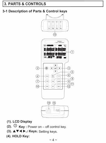
3. PARTS & CONTROLS
3-1 Description of Parts & Control keys
8
MAX MIN
ALARM
-
INTVm:sd-h
FULLNO.
T 4T 3
T 2T 1
5
13
1011
7
4
3
6
1514
12
9
2
1
(1). LCD Display (2). Key : Power on – off control key.(3). Keys: Setting keys.(4). HOLD Key:
~ 4 ~

Data hold function key, press “HOLD” key to hold data, the “ H ” symbol is displayed, press this key again to exit this function.
Press and hold down “HOLD” key then press " " key to turn on the meter, the “ ” symbol disappear, exit auto power off function.
(5). MAX MIN Key: Press “MAX MIN” key to circulate the reading of Maximum, Minimum, Maximum minus Minimum, and Current. Press this key for 2 seconds to exit this mode.
(6). °C / °F Key: Press “°C / °F” key to switch the units between Celsius (°C) and Fahrenheit (°F).
(7). TYPE Key: Press "TYPE" key to enter the thermocouple type select mode, press this key again to exit this mode.
(8). TIME Key: Press “TIME” key to circulate display data and time.
(9). ALARM Key: Press “ALARM” key to enable or disable Alarm function.
(10). MEM Key: Manual data memory control key. (11). SET Key: Press “SET” key to start or exit setup. (12). READ Key: Manual memory data reading control key. (13). T1, T2, T3, T4 : Thermocouple T1, T2, T3 and T4 inputs. (14). USB Interface Jack.(15). AC Adaptor Input Jack.
3-2 Description of Display
MAX MIN
ALARM
-
INTVm:sd-h
FULLNO.
T 4T 3
T 2T 1
~ 5 ~

°F, °C : Temperature units. : Auto power off indication.
OFFSET : The thermocouple measurement includes an offset indication.
REC : MAX MIN Recording mode and current reading indication. REC MAX : Maximum reading indication. REC MIN : Minimum reading indication. REC MAX-MIN : Maximum minus Minimum value indication. H : Data hold function indication. SET : Setting mode indication.
: Thermocouple type indication. ALARM : Alarm mode indication.
ALARM : Input temperature exceeds the high limit value indication.
ALARM : Input temperature is below the low limit value indication. T1, T2, T3, T4 : Thermocouple T1, T2, T3, T4 input temperature
measurement display. : Battery capacity indication.
: Replace batteries indication.
NO. : Last manual data memory address number indication (01–99). M : Manual data memory indication, M displays one time store one
sets data into the memory. NO. R : Manual data memory read address number indication,
the memory data displayed for read. A-M : Auto data logging indication, A-M will disappear after storing
the data. INTV : Auto data log interval time setting indication.
~ 6 ~

Full : Auto data logged memory full indication, if exceeds 255 memory blocks, total maximum record capacity size is 36,000 sets of data for 4 input thermocouple temperature measurement (100,000 sets data for 1 input record).
m:s : Time display indication.
4. OPERATION INSTRUCTION
WARNING Before using the meter inspect the case. Do not use the meter if it appears damaged. Look for cracks or missing plastic. Pay particular attention to the insulation around the connectors.
Disconnect thermocouples from the meter before opening the case.
Replace the batteries as soon as the battery indicator “ ” appears. The possibility of false reading can lead to personal injury.
Do not use the meter if it operates abnormally. Protection may be impaired.
Do not operate the meter around explosive gas, vapor or dust. Do not use the meter with any part of the case or cover removed.
4-1 Setting the meter 1. Real – Time setting:
(a). Press " " key to turn on the meter. (b). Press “SET” key to enter the setting mode, the “Set clock”
and “ SET ” symbols are displayed. (c). Press " " key to enter real time setting mode and the two
flicking numbers of year. (d). Press or key to set the year (real time).
~ 7 ~
(e). Press " " key and move to the two flicking digits of month. (f). Press or key to set month (real time). (g). Press " " key and move to the two flicking digits of day. (h). Press or key to set day (real time). (i). Press " " key and move to the two flicking digits of hour. (j). Press or key to set hour (real time). (k). Press " " key and move to the two flicking digits of
minutes.(l). Press or key to set minutes (real time). (m). Press " " key and move to the two flicking digits of second. (n). Press or key to set seconds (real time). (o). Press " " key to store real time values. (r). Press “SET” key to exit this mode.
2. Interval – Time setting : The logging interval time determines how often the meter stores logged readings in memory. (a). Press " " key to turn on the meter. (b). Press “SET” key to enter the setting mode, then press or
key until the display shows “Set Intr”. (c). Press "" key to enter the interval time setting mode and the
three flicking numbers of second. (d). Press or key to set the desired second of interval time
(1 to 255 seconds). (e). Press " " key to store the auto datalogging interval time. (f). Press “SET” key to exit this mode.
3. Offset setting : You can adjust the meter readings to compensate for the errors of a specific thermocouple. The allowable adjustment range is from +12.7 to -12.8 degree, regardless of the temperature units. You can store individual offsets for T1, T2, T3 and T4. (a). Press " " key to turn on the meter. (b). Press “SET” key to enter the setting mode, then press or
key until the display shows “SEt OFSEt”.
~ 8 ~

(c). Press " " key to enter the offset setting mode, the “ OFFSET ” symbol is displayed.
(d). Press or key to select the desired T1, T2, T3 or T4. (e). Press or key to set the desired offset values. (f).. Press "" key to store the offset value. (g). Press “SET” key to exit this mode.
The temperature measurement plus the offset appears in the display. Remember to set the offset to 0.0 when it is no longer needed. The “ OFFSET ” symbol will disappear when the offset values all are 0.0.
4. Auto Power Off Time setting : (a). Press " " key to turn on the meter. (b). Press “SET” key to enter the setting mode, then press or
key until the display shows “SEt SLEEP”.(c). Press " " key to enter the auto power off time setting mode,
the “SLEEP” symbol is displayed. (d). Press or key to choose the desired auto power off
time. The choices are: 5, 15 and 30 minutes. (e). Press " " key to store the choice. (f). Press “SET” key to exit this mode.
5. Alarm High / Low Limit setting : (a). Press " " key to turn on the meter. (b). Press “SET” key to enter the setting mode, then press or
key until the display shows “SEt ALArn”. (c). Press " " key to enter the alarm high limit and low limit
setting mode, the “ ALARM ” symbol is displayed. (d). Press or key to select the desired T1, T2, T3 or T4. (e). Press " " key to enter the high limit value setting, the “ ”
symbol is displayed. (f). Press or key to set the desired alarm high limit value,
the resolution of setting value is 0.1 degree, regardless of the temperature units.
-9-

(g). Press " " key to store the alarm high limit value and to enter the alarm low limit value setting, the symbol “ ” is displayed.
(h). Press or key to set the desired alarm low limit value, the resolution of setting value is 0.1 degree, regardless of the temperature units.
(i). Press " " key to store alarm low limit value. You can store individual alarm High / Low limit values for T1, T2, T3 and T4, by repeating (c) to (i) procedure.
(j). Press “SET” key to exit this mode. (k). Press “ALARM” key to enter the alarm function, the
“ALARM” symbol is displayed. When the measured temperature value exceeds the setting High temperature value (the “ ” symbol will flicker the display) or below the setting Low temperature value (the “ ” symbol will flicking display.) the beep will sound one time per 4 seconds.
(l). Press “ALARM” key again to exit the alarm function. 4-2 Setting the Thermocouple Type
1. Press " " key to turn on the meter. 2. Press “TYPE” key to enter the thermocouple type choices.
The currently selected thermocouple type blinks. 3. Press or key to select the desired T1, T2, T3 or T4. 4. Press or key until the thermocouple type you want
appears on the display. 5. Press " " key to store the thermocouple type. You can
store individual thermocouple types for T1, T2, T3 and T4, by repeated (3) to (5) procedure.
6. Press “TYPE” key again to exit this choices. 4-3 Temperature Measurement
1. Press " " key to turn on the thermometer. 2. Plug the thermocouple (s) into the thermocouple input. If no
thermocouple is plugged into the selected input or the thermocouple is "open", the display will show "- - -".
~ 10 ~

3. Press "°C / °F" key to desired temperature scale. 4. Perform measurements by contacting the object being
measured with the probe sensor. 5. Read the temperature on the display. The display shows
“OL” (overload) or “Un” (under ranges) when the temperature being measured is outside the meter valid range.
4-4 Maximum (MAX), Minimum (MIN) Recording Measurement
1. Press “MAX MIN” key to enter the recording mode, the “ REC ” symbol is displayed.
2. Press “MAX MIN” key to circulate the display of the maximum (REC MAX), minimum (REC MIN), maximum minus minimum (REC MAX-MIN) and current REC) reading.
3. Press “HOLD” key to paused recording, the “H” symbol is displayed, press “HOLD” key again will resume recording.
4. Press “MAX MIN” key for 2 seconds to exit this mode.
4-5 Manual Data Memory and Read Function Operation 1. Clear the manual memorized data
(a). Press " " key to turn off the meter. (b). Press and hold down “MEM” key, then press " " key again to
turn on the meter, the “CLr YES no M” symbol is displayed. (c). Press or key to select “YES” symbol is displayed
flicking. (d). Press " " key to clear the manual memorized data. (e). Press " " key again to exit this mode.
2. Store manual data to memory (a). Pressing “MEM” key one time will store one set of
measured data to memory. The “M” symbol will disappear and the stored memory address will displayed.
(b). Maximum store memory capacity size is 99 sets. ~ 11 ~
3. Read the manual store data (a). Press “READ” key to enter the read mode, the “R” symbol
is displayed. (b). Press or key to read the memories data, the
memories data address will be displayed. (c). Press “READ” key again to exit this mode.
4-6 Auto Datalogging Function Operation 1. Clear the Auto datalogged data :
Before entering into the clear memory data mode, users must down load the previous memory data to PC. (a). Press " " key to turn off the meter. (b). Press and hold down “MEM” key, then press " " key again
to turn on the meter, the “CLr YES no M” symbol is displayed.
(c). Press "" key to enter the clear auto datalogged data mode, the “CLr YES no AM” symbol is displayed.
(d). Press or key to select “YES” symbol is displayed flickering
(e). Press " " key to clear the auto datalogged data and exit this mode.
2. Store Auto datalogging data to memory : (a). Press “MEM” key for 3 seconds to start auto datalogging,
the “A-M” symbol is displayed, the “A-M” symbol according to the interval time will disappear after storing one set of data into the memory.
(b). Press “MEM” key for 3 seconds to stop data record, the current block number will be displayed for one second. Press “MEM” key for 3 seconds will resume data record, but maximum is divided to 255 memory blocks. Total maximum record capacity size is 36,000 sets data for 4
-12-
(b). input thermocouple temperature measurement (100,000 sets data for 1 input record).
(c). When maximum block or maximum capacity is full, the “FULL” symbol will be displayed, the data record is auto stopped.
3. Download data to PC : Please refer to the software manual (CD-ROM) to download the data.
4-7 Disable Auto Power off Function The meter will automatically enter sleep mode approx. 5, 15 or 30 minutes decided by user setting to save power consumption.
1. Disable auto power off procedure : (a). Press " " key to turn off the meter. (b). Press and hold down "HOLD" key then press " " key to
turn on the meter, the auto power off function will be disabled, and the auto power off symbol “ ” will disappear.
2. Auto power off mode is enabled each time you turn on the meter and is automatically disabled bt the follow modes : (a). MAX MIN record mode. (b). Auto datalogging function is active. (c). PC linked.
5. MAINTENANCE
5-1 General Maintenance 1. Clean the meter and accessories with a damp cloth and a mild
soap. Do not use abrasives, solvent or alcohol.
~ 13 ~

5-2 Battery Replacement :
WARNING To AVOID electrical shock, remove any inputs before replacing the batteries.
1. When operating the meter on batteries, periodically check the battery symbol to determine the remaining battery capacity. The number of black segments decreases as the batteries are used up. When the “ ” symbol display starts to flash, correct measurement is no longer possible. Replace the batteries with a fresh set.
2. Take care not to reverse the (+) and (-) polarity when inserting the batteries. Always replace all six batteries together. Do not mix old and new batteries or batteries of different type. Remove the batteries from the meter, if the meter is not to be used for a month or longer.
6. USB INTERFACE, SOFTWARE INSTALLATION AND OPERATION
For the detailed instruction, please refer to the content of attached CD-ROM, which has the complete instruction of software operation and relevant information. Protocol : are enclosed within the content of CD-ROM,
please open the CD-ROM for details.
※ All rights reserved.
※ Do not reproduce without authorization.

Servicing North America:U.S.A.: Omega Engineering, Inc., One Omega Drive, P.O. Box 4047ISO 9001 Certified Stamford, CT 06907-0047
Toll-Free: 1-800-826-6342 Tel: (203) 359-1660FAX: (203) 359-7700 e-mail: [email protected]
Canada: 976 BergarLaval (Quebec), Canada H7L 5A1Toll-Free: 1-800-826-6342 TEL: (514) 856-6928FAX: (514) 856-6886 e-mail: [email protected]
For immediate technical or application assistance:U.S.A. and Canada: Sales Service: 1-800-826-6342/1-800-TC-OMEGA®
Customer Service: 1-800-622-2378/1-800-622-BEST®
Engineering Service: 1-800-872-9436/1-800-USA-WHEN®
Mexico: En Español: 001 (203) 359-7803 FAX: (001) [email protected] e-mail: [email protected]
Servicing Europe:Benelux: Managed by the United Kingdom Office
Toll-Free: 0800 099 3344 TEL: +31 20 347 21 21FAX: +31 20 643 46 43 e-mail: [email protected]
Czech Republic: Frystatska 184733 01 Karviná, Czech RepublicToll-Free: 0800-1-66342 TEL: +420-59-6311899FAX: +420-59-6311114 e-mail: [email protected]
France: Managed by the United Kingdom OfficeToll-Free: 0800 466 342 TEL: +33 (0) 161 37 29 00FAX: +33 (0) 130 57 54 27 e-mail: [email protected]
Germany/Austria: Daimlerstrasse 26D-75392 Deckenpfronn, GermanyToll-Free: 0 800 6397678 TEL: +49 (0) 7059 9398-0FAX: +49 (0) 7056 9398-29 e-mail: [email protected]
United Kingdom: OMEGA Engineering Ltd.ISO 9001 Certified One Omega Drive, River Bend Technology Centre, Northbank
Irlam, Manchester M44 5BD EnglandToll-Free: 0800-488-488 TEL: +44 (0)161 777-6611FAX: +44 (0)161 777-6622 e-mail: [email protected]
OMEGAnet® Online Service Internet e-mailomega.com [email protected]
It is the policy of OMEGA Engineering, Inc. to comply with all worldwide safety and EMC/EMIregulations that apply. OMEGA is constantly pursuing certification of its products to the European NewApproach Directives. OMEGA will add the CE mark to every appropriate device upon certification.The information contained in this document is believed to be correct, but OMEGA accepts no liability for anyerrors it contains, and reserves the right to alter specifications without notice.WARNING: These products are not designed for use in, and should not be used for, human applications.
WARRANTY/DISCLAIMEROMEGA ENGINEERING, INC. warrants this unit to be free of defects in materials andworkmanship for a period of 13 months from date of purchase. OMEGA’s WARRANTY addsan additional one (1) month grace period to the normal one (1) year product warranty tocover handling and shipping time. This ensures that OMEGA’s customers receive maximumcoverage on each product. If the unit malfunctions, it must be returned to the factory for evaluation. OMEGA’s CustomerService Department will issue an Authorized Return (AR) number immediately upon phone orwritten request. Upon examination by OMEGA, if the unit is found to be defective, it will berepaired or replaced at no charge. OMEGA’s WARRANTY does not apply to defects resultingfrom any action of the purchaser, including but not limited to mishandling, improperinterfacing, operation outside of design limits, improper repair, or unauthorized modification.This WARRANTY is VOID if the unit shows evidence of having been tampered with or showsevidence of having been damaged as a result of excessive corrosion; or current, heat, moistureor vibration; improper specification; misapplication; misuse or other operating conditionsoutside of OMEGA’s control. Components in which wear is not warranted, include but are notlimited to contact points, fuses, and triacs.OMEGA is pleased to offer suggestions on the use of its various products. However, OMEGA neither assumes responsibility for any omissions or errors nor assumesliability for any damages that result from the use of its products in accordance withinformation provided by OMEGA, either verbal or written. OMEGA warrants onlythat the parts manufactured by the company will be as specified and free ofdefects. OMEGA MAKES NO OTHER WARRANTIES OR REPRESENTATIONS OF ANYKIND WHATSOEVER, EXPRESSED OR IMPLIED, EXCEPT THAT OF TITLE, AND ALLIMPLIED WARRANTIES INCLUDING ANY WARRANTY OF MERCHANTABILITY ANDFITNESS FOR A PARTICULAR PURPOSE ARE HEREBY DISCLAIMED. LIMITATION OFLIABILITY: The remedies of purchaser set forth herein are exclusive, and the totalliability of OMEGA with respect to this order, whether based on contract, warranty,negligence, indemnification, strict liability or otherwise, shall not exceed thepurchase price of the component upon which liability is based. In no event shallOMEGA be liable for consequential, incidental or special damages.CONDITIONS: Equipment sold by OMEGA is not intended to be used, nor shall it be used: (1)as a “Basic Component” under 10 CFR 21 (NRC), used in or with any nuclear installation oractivity; or (2) in medical applications or used on humans. Should any Product(s) be used in orwith any nuclear installation or activity, medical application, used on humans, or misused inany way, OMEGA assumes no responsibility as set forth in our basic WARRANTY/ DISCLAIMERlanguage, and, additionally, purchaser will indemnify OMEGA and hold OMEGA harmless fromany liability or damage whatsoever arising out of the use of the Product(s) in such a manner.
RETURN REQUESTS/INQUIRIESDirect all warranty and repair requests/inquiries to the OMEGA Customer Service Department.BEFORE RETURNING ANY PRODUCT(S) TO OMEGA, PURCHASER MUST OBTAIN ANAUTHORIZED RETURN (AR) NUMBER FROM OMEGA’S CUSTOMER SERVICE DEPARTMENT(IN ORDER TO AVOID PROCESSING DELAYS). The assigned AR number should then bemarked on the outside of the return package and on any correspondence.The purchaser is responsible for shipping charges, freight, insurance and proper packaging toprevent breakage in transit.
FOR WARRANTY RETURNS, please havethe following information available BEFORE contacting OMEGA:1. Purchase Order number under which
the product was PURCHASED,2. Model and serial number of the product
under warranty, and3. Repair instructions and/or specific
problems relative to the product.
FOR NON-WARRANTY REPAIRS, consultOMEGA for current repair charges. Have thefollowing information available BEFORE contacting OMEGA:1. Purchase Order number to cover the
COST of the repair,2. Model and serial number of theproduct, and3. Repair instructions and/or specific problems
relative to the product.OMEGA’s policy is to make running changes, not model changes, whenever an improvement is possible. This affords our customers the latest in technology and engineering.OMEGA is a registered trademark of OMEGA ENGINEERING, INC.© Copyright 2009 OMEGA ENGINEERING, INC. All rights reserved. This document may not be copied, photocopied,reproduced, translated, or reduced to any electronic medium or machine-readable form, in whole or in part, withoutthe prior written consent of OMEGA ENGINEERING, INC.

Where Do I Find Everything I Need for Process Measurement and Control?
OMEGA…Of Course!Shop online at omega.com SM
TEMPERATUREThermocouple, RTD & Thermistor Probes, Connectors, Panels & AssembliesWire: Thermocouple, RTD & ThermistorCalibrators & Ice Point ReferencesRecorders, Controllers & Process MonitorsInfrared Pyrometers
PRESSURE, STRAIN AND FORCETransducers & Strain GagesLoad Cells & Pressure GagesDisplacement TransducersInstrumentation & Accessories
FLOW/LEVELRotameters, Gas Mass Flowmeters & Flow ComputersAir Velocity IndicatorsTurbine/Paddlewheel SystemsTotalizers & Batch Controllers
pH/CONDUCTIVITYpH Electrodes, Testers & AccessoriesBenchtop/Laboratory MetersControllers, Calibrators, Simulators & PumpsIndustrial pH & Conductivity Equipment
DATA ACQUISITIONData Acquisition & Engineering SoftwareCommunications-Based Acquisition SystemsPlug-in Cards for Apple, IBM & CompatiblesDatalogging SystemsRecorders, Printers & Plotters
HEATERSHeating CableCartridge & Strip HeatersImmersion & Band HeatersFlexible HeatersLaboratory Heaters
ENVIRONMENTALMONITORING AND CONTROL
Metering & Control InstrumentationRefractometersPumps & TubingAir, Soil & Water MonitorsIndustrial Water & Wastewater TreatmentpH, Conductivity & Dissolved Oxygen Instruments
M4945/0810