magnetocaloric materials not only for cooling applications · magnetocaloric materials not only for...
TRANSCRIPT
Magnetocaloric Materials not only for cooling applications
Ekkes Brück
Fundamental Aspects of Materials and Energy,
Radiation Radionuclides Reactors, TNW,
Delft University of Technology, The Netherlands
Introduction
Magnetic cooling
Giant magnetocaloric effect
power generation
Review: E. Brück, Magnetic refrigeration near room temperature, Handbook of magnetic materials Vol 17 chapt. 4 (2007) ed. K.H.J. Buschow
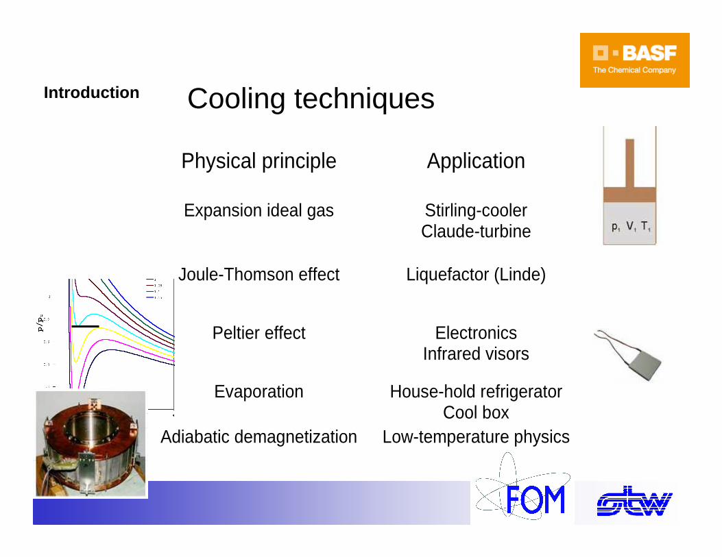
Cooling techniques
Physical principle Application
Expansion ideal gas Stirling-cooler Claude-turbine
Joule-Thomson effect Liquefactor (Linde)
Peltier effect Electronics Infrared visors
Evaporation House-hold refrigerator Cool box
Adiabatic demagnetization Low-temperature physics
Introduction
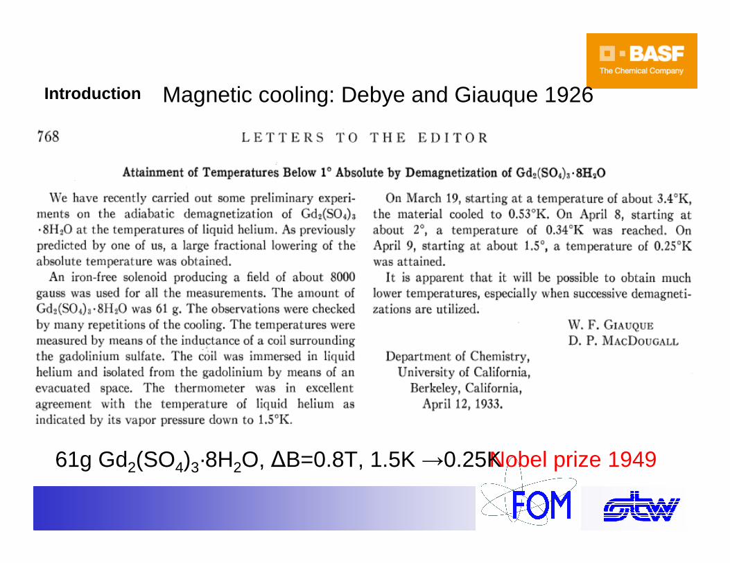
Magnetic cooling: Debye and Giauque 1926
Nobel prize 194961g Gd2(SO4)3·8H2O, ∆B=0.8T, 1.5K →0.25K
Introduction
Introduction
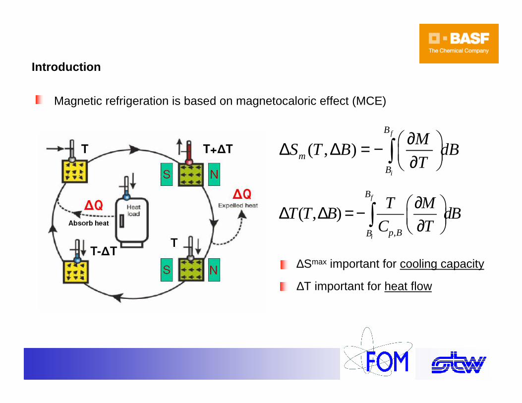
Magnetic refrigeration is based on magnetocaloric effect (MCE)
∆Smax important for cooling capacity
∆T important for heat flow
( , )f
i
B
m
B
MS T B dB
T
∂ ∆ ∆ = − ∂ ∫
,
( , )f
i
B
p BB
T MT T B dB
C T
∂ ∆ ∆ = − ∂ ∫
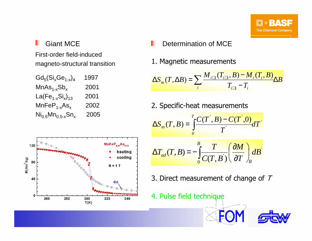
4. Pulse field technique
3. Direct measurement of change of T
BTT
BTMBTMBTS
i ii
iiiim ∆
−−=∆∆ ∑
+
++
1
11 ),(),(),(
1. Magnetic measurements
'
0'),(
),( dBT
M
BTC
TBTT
B
Bad ∫
∂∂−=∆
'
0'
'' )0,(),(),( dT
T
TCBTCBTS
T
m ∫−=∆
2. Specific-heat measurements
Determination of MCE
Gd5(SixGe1-x)4 1997
MnAs1-xSbx 2001
La(Fe1-xSix)13 2001MnFeP1-xAsx 2002
Ni0.5Mn0.5-xSnx 2005
Giant MCE
First-order field-induced
magneto-structural transition
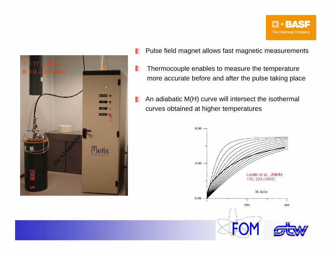
Pulse field technique
An adiabatic M(H) curve will intersect the isothermal
curves obtained at higher temperatures
Pulse field magnet allows fast magnetic measurements
Thermocouple enables to measure the temperature
more accurate before and after the pulse taking place
T = 77 – 400 KB = 0 – 20 Tesla
150
kJ c
apac
itor

Transition-metal compounds
High abundance (low price)
Intermediate magnetic moment (moderate MC effect)
Frequently Curie temperatures exceeding RT
Strong coupling to lattice (Simultaneous magnetic and structural transitions or metamagnetism)
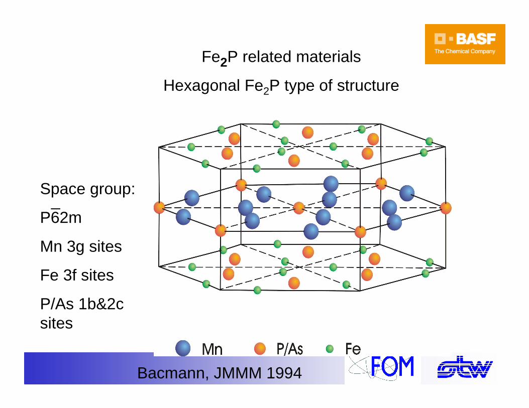
Fe2P related materials
Hexagonal Fe2P type of structure
Bacmann, JMMM 1994
Space group:
P62m
Mn 3g sites
Fe 3f sites
P/As 1b&2c sites
_
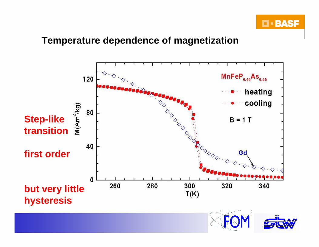
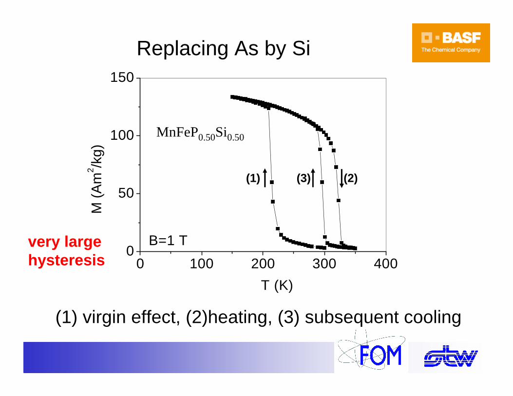
Temperature dependence of magnetization
Step-liketransition
first order
but very littlehysteresis
0 100 200 300 4000
50
100
150
T (K)
M (
Am
2 /kg)
B=1 T
(1) (2)(3)
Replacing As by Si
(1) virgin effect, (2)heating, (3) subsequent cooling
MnFeP0.50Si0.50
very largehysteresis
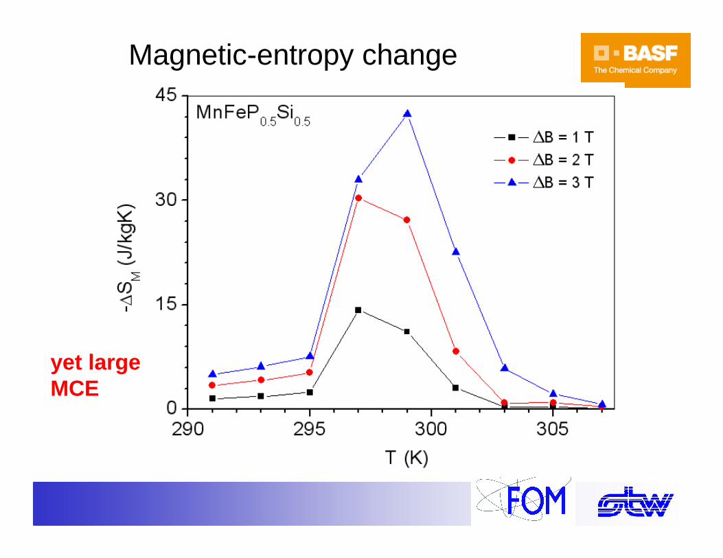
Magnetic-entropy change
yet largeMCE
0 1 2 3 4 5 60
20
40
60
80
100
120
140
270 276 282 288 294 3000
10
20
30
40
50
60
70
80
90
B (T)
M (A
m2 /k
g)
269 K
303 K∆∆ ∆∆T
= 2 K
1 T 2 T 3 T 4 T 5 T
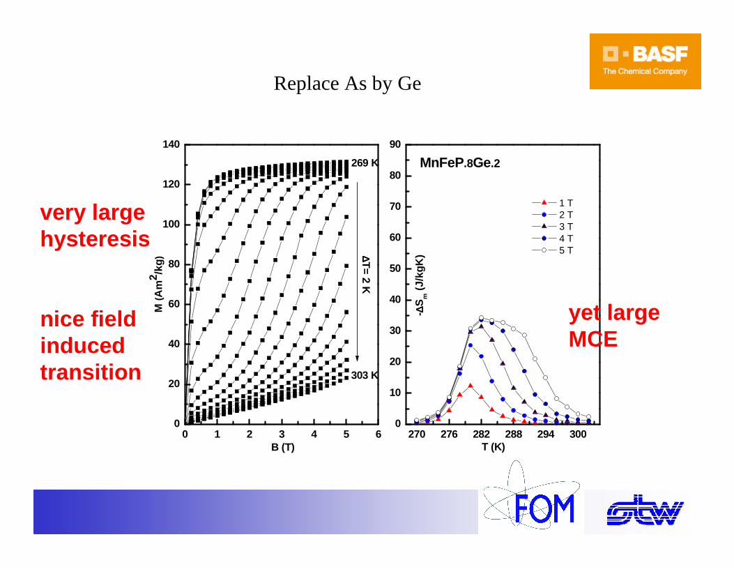
MnFeP.8Ge.2
T (K)
- ∆∆ ∆∆S
m (
J/kg
K)
Replace As by Ge
very largehysteresis
nice field induced transition
yet largeMCE

Concentration dependence of TCfor Ge and As
0.2 0.4 0.6150
200
250
300
350
400
450
500
550
600
MnFe(P1-x,Gex) MnFe(P1-x,Asx)
Cur
ie te
mpe
ratu
re (
K)
Concentration x
Almost linear concentration dependence.
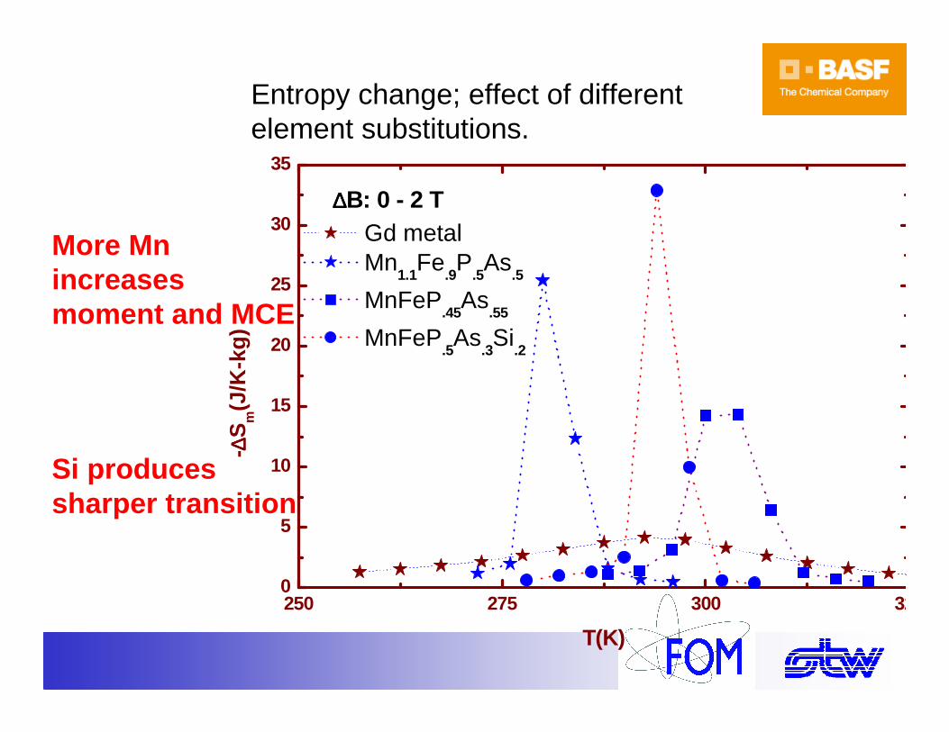
Entropy change; effect of different element substitutions.
250 275 300 3250
5
10
15
20
25
30
35
Gd metal Mn
1.1Fe
.9P
.5As
.5
MnFeP.45
As.55
MnFeP.5As
.3Si
.2
- ∆∆ ∆∆S
m(J
/K-k
g)
T(K)
∆∆∆∆B: 0 - 2 T
More Mnincreases moment and MCE
Si produces sharper transition
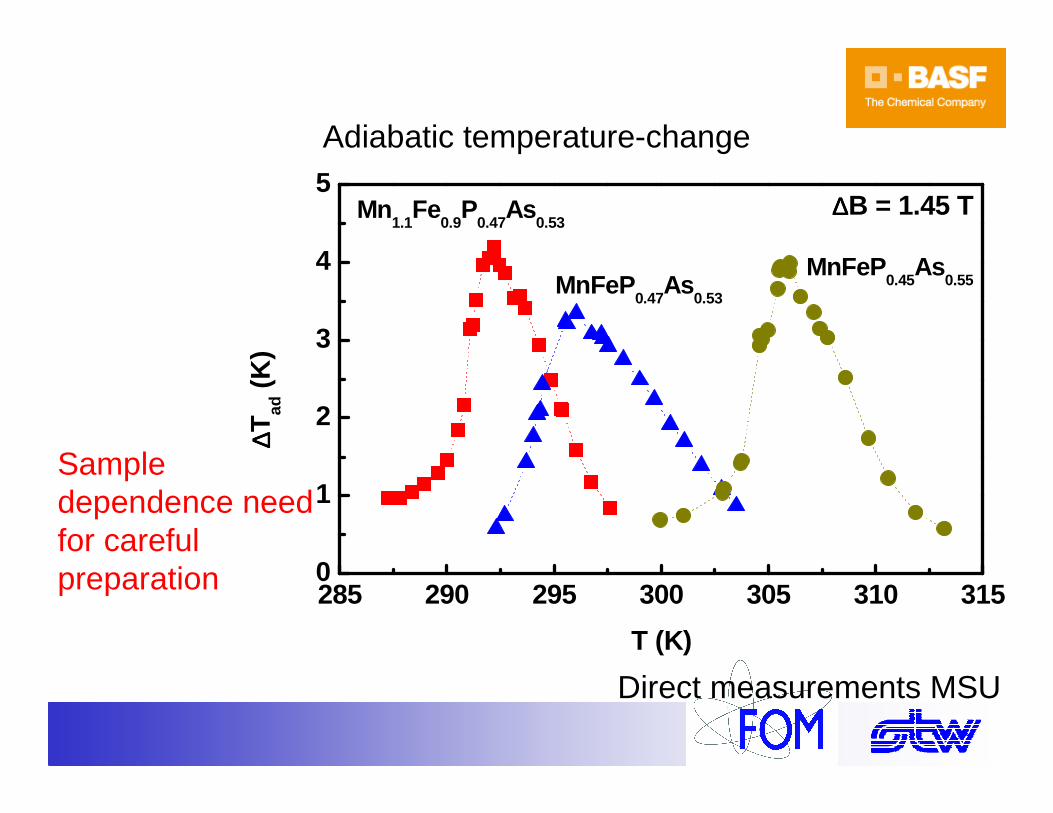
285 290 295 300 305 310 3150
1
2
3
4
5∆∆∆∆B = 1.45 T
MnFeP0.45
As0.55MnFeP
0.47As
0.53
Mn1.1
Fe0.9
P0.47
As0.53
∆∆ ∆∆ Tad
(K
)
T (K)
Direct measurements MSU
Adiabatic temperature-change
Sample dependence need for careful preparation
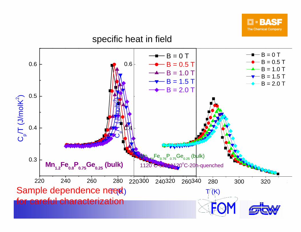
220 240 260 280 300 320 340
0.3
0.4
0.5
0.6
Cp/T
(J/
mol
K2 )
T (K)
B = 0 T B = 0.5 T B = 1.0 T B = 1.5 T B = 2.0 T
Mn1.2
Fe0.8
P0.75
Ge0.25
(bulk)
specific heat in field
Sample dependence need for careful characterization
220 240 260 280 300 320 340
0.4
0.6
Cp/
T (
J/m
olK
2 )
T (K)
B = 0 T B = 0.5 T B = 1.0 T B = 1.5 T B = 2.0 T
Mn1.24
Fe0.76
P0.75
Ge0.25
(bulk)
1120oC-cdw-1120oC-20h-quenched
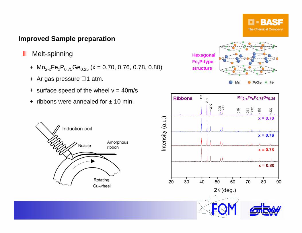
Improved Sample preparation
Melt-spinning
+ Ar gas pressure ∼ 1 atm.
surface speed of the wheel v = 40m/s+
ribbons were annealed for ± 10 min.+
Mn2-xFexP0.75Ge0.25 (x = 0.70, 0.76, 0.78, 0.80)+
Hexagonal Fe2P-type structure
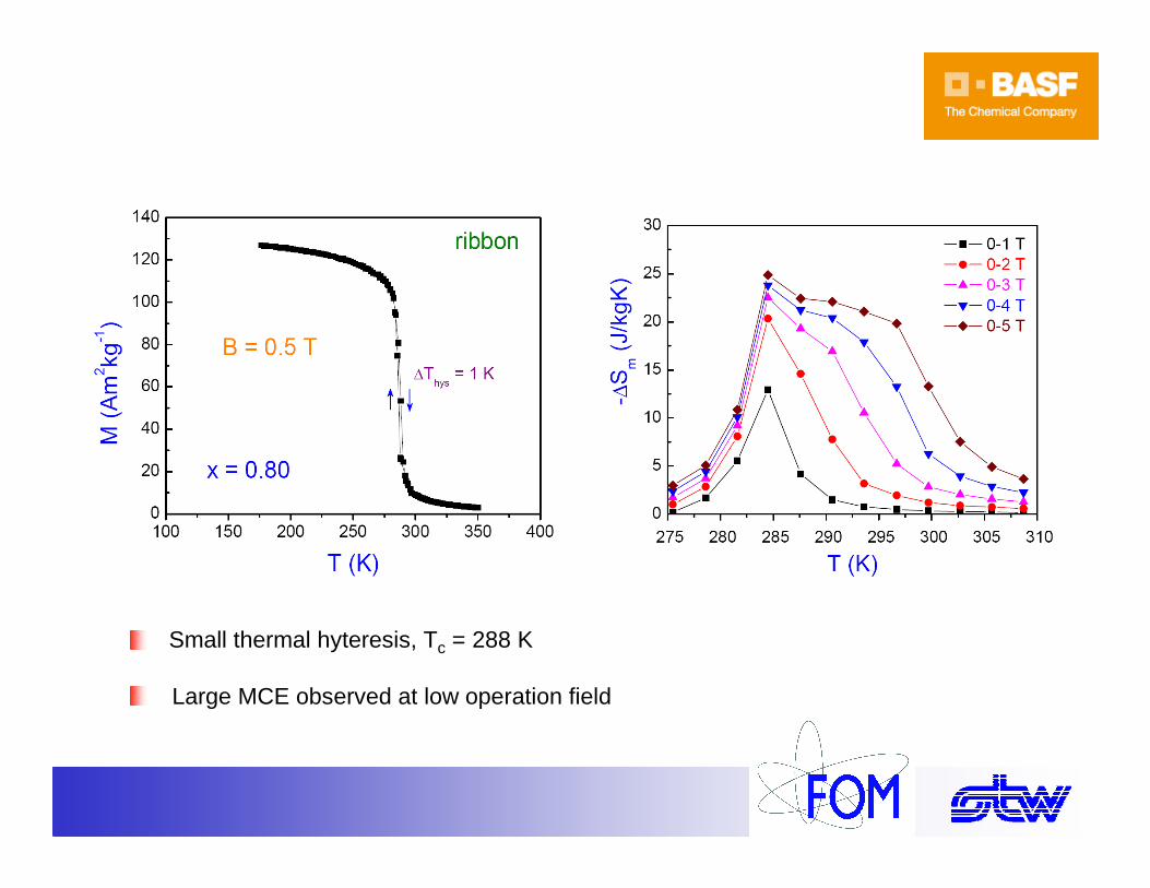
Experimental results
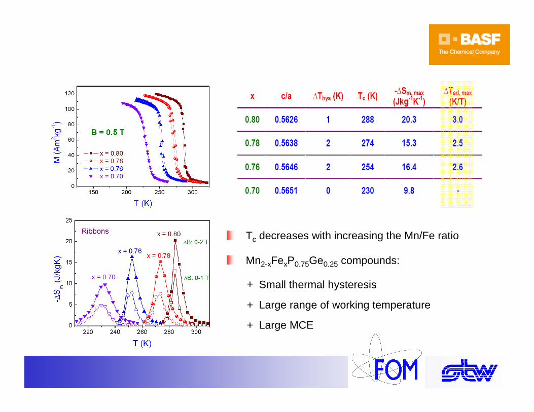
Small thermal hyteresis, Tc = 288 K
Large MCE observed at low operation field
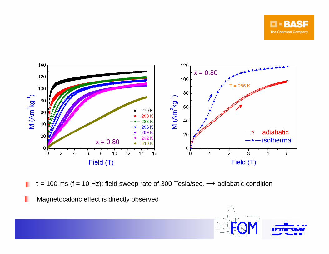
Experimental results
Magnetocaloric effect is directly observed
τ = 100 ms (f = 10 Hz): field sweep rate of 300 Tesla/sec. → adiabatic condition

Experimental results
∆Tad (H) is constructed via the crossing points of the adiabatic curve with the set of isothermal curves
For x = 0.80: ∆Tad ≈ 3 K/Tesla
Experimental results
Tc decreases with increasing the Mn/Fe ratio
Mn2-xFexP0.75Ge0.25 compounds:
Large MCE+
Small thermal hysteresis+
Large range of working temperature+
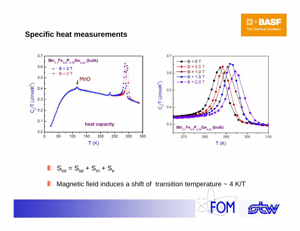
Specific heat measurements
Stot = Slat + Sm + Se
Magnetic field induces a shift of transition temperature ~ 4 K/T
MnO
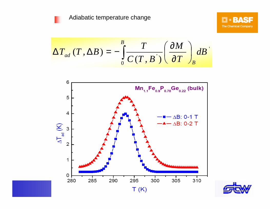
'
0' ),(
),( dBT
M
BTC
TBTT
B
Bad ∫
∂∂−=∆∆
Adiabatic temperature change
Field driven 1st order magnetoelastictransition 150 K < Tc < 450 K .
MnFe(P,As) hexagonal above magnetic transition
hexagonal below.
Hardly any volume change( <0.1 %) but change of c/a.
Summary MnFe(P,As,Si,Ge)
dBT
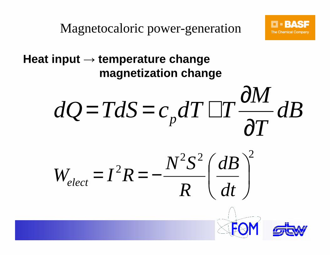
MTdTcTdSdQ p ∂
∂+==
Heat input → temperature changemagnetization change
2222
−==dt
dB
R
SNRIWelect
Magnetocaloric power-generation
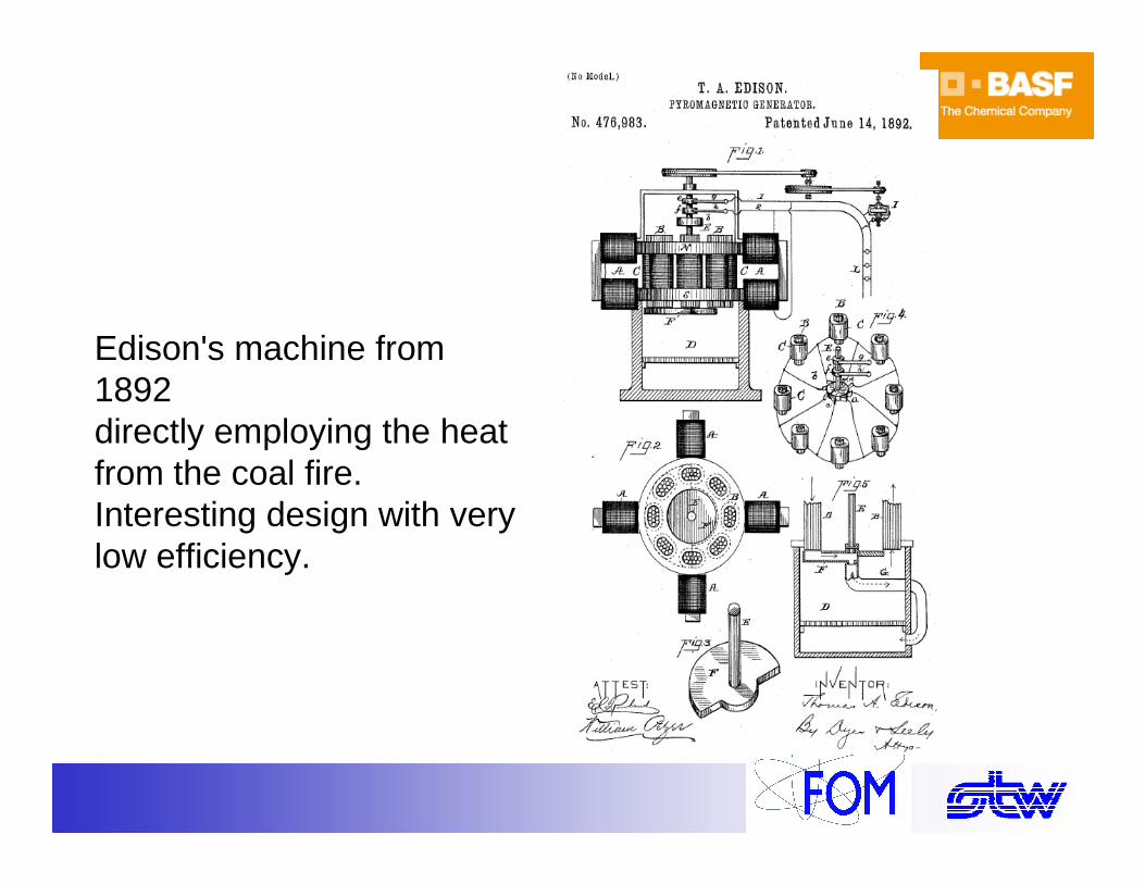
Edison's machine from 1892 directly employing the heat from the coal fire.Interesting design with very low efficiency.
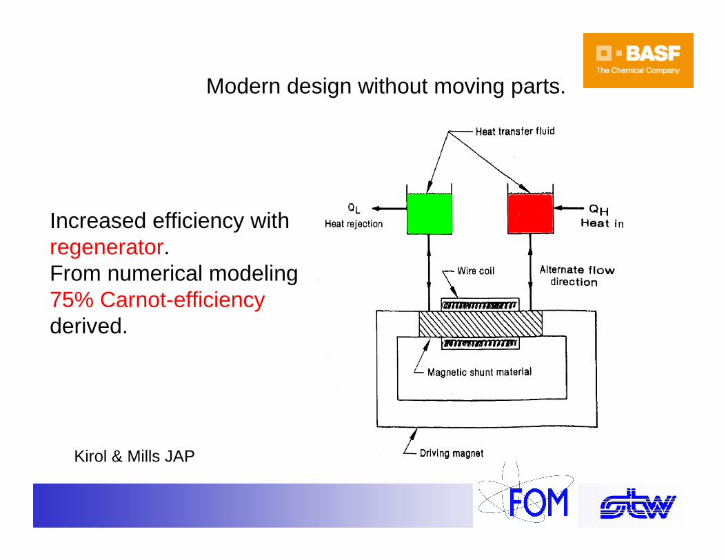
Increased efficiency with regenerator.From numerical modeling 75% Carnot-efficiencyderived.
Modern design without moving parts.
Kirol & Mills JAP

0
25
20
15
10
5
0
0 20 40 60 80
T (C0)
∆S (
J/K
·kg)
Increased T span with active magnetic regenerator containing different materials with tailored TC
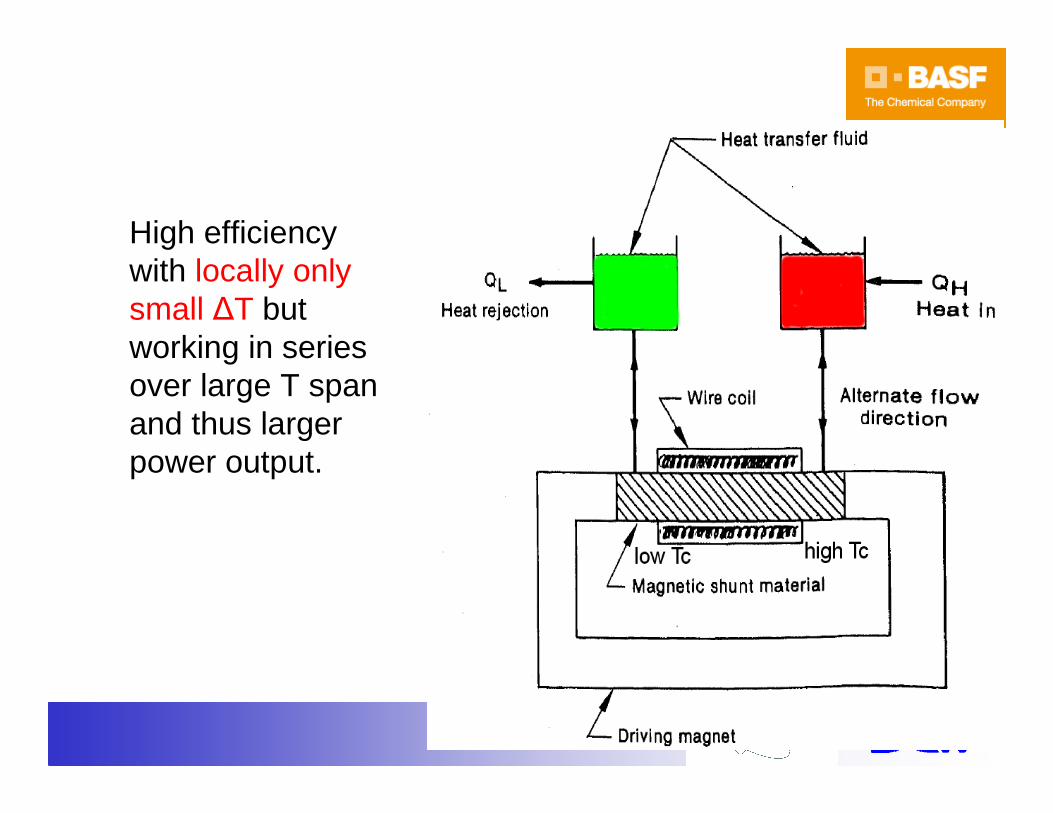
High efficiency with locally only small ∆T but working in series over large T span and thus larger power output.
Magnetocaloricenergy converter
Other heat
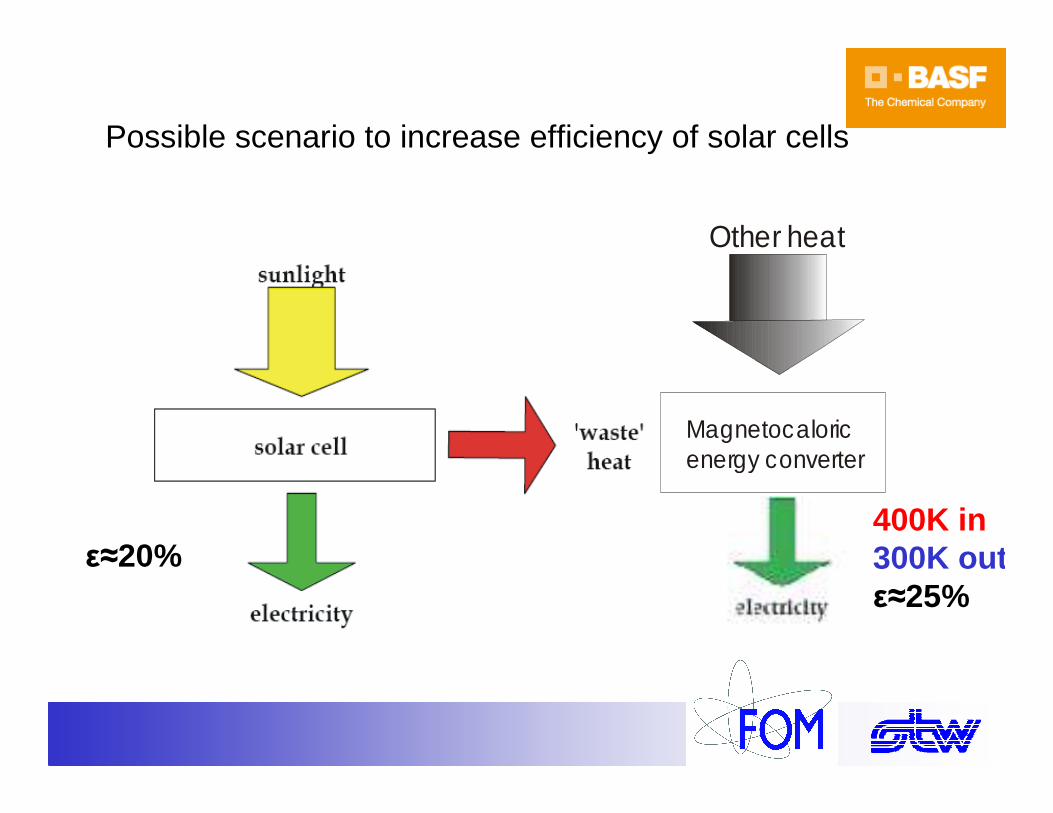
Possible scenario to increase efficiency of solar cells
ε≈20%400K in300K outε≈25%
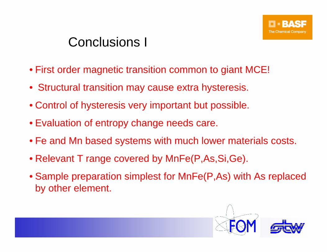
Conclusions I
• First order magnetic transition common to giant MCE!
• Structural transition may cause extra hysteresis.
• Control of hysteresis very important but possible.
• Evaluation of entropy change needs care.
• Fe and Mn based systems with much lower materials costs.
• Relevant T range covered by MnFe(P,As,Si,Ge).
• Sample preparation simplest for MnFe(P,As) with As replaced by other element.
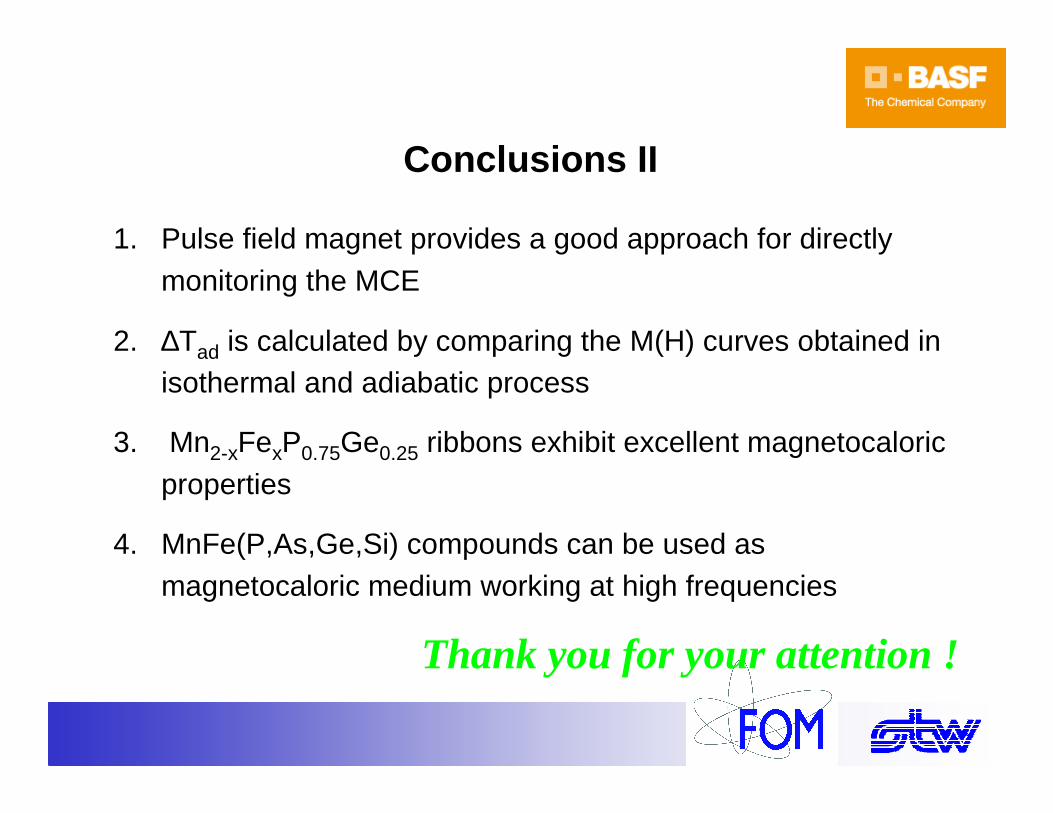
Conclusions II
1. Pulse field magnet provides a good approach for directly monitoring the MCE
2. ∆Tad is calculated by comparing the M(H) curves obtained in isothermal and adiabatic process
3. Mn2-xFexP0.75Ge0.25 ribbons exhibit excellent magnetocaloric properties
4. MnFe(P,As,Ge,Si) compounds can be used as magnetocaloric medium working at high frequencies
Thank you for your attention !