magnetowetting and sliding motion of a sessile ferrofluid...
TRANSCRIPT
DOI: 10.1021/la101474e 12553Langmuir 2010, 26(15), 12553–12559 Published on Web 07/07/2010
pubs.acs.org/Langmuir
© 2010 American Chemical Society
Magnetowetting and Sliding Motion of a Sessile Ferrofluid Droplet
in the Presence of a Permanent Magnet
Nam-Trung Nguyen,* Guiping Zhu, Yong-Chin Chua, Vinh-Nguyen Phan, andSay-Hwa Tan
School of Mechanical and Aerospace Engineering, Nanyang Technological University,50 Nanyang Avenue, Singapore, Singapore 639798
Received April 14, 2010. Revised Manuscript Received June 18, 2010
Motion of a droplet on a planar surface has applications in droplet-based lab on a chip technology. This paper reportsthe experimental results of the shape, contact angles, andmotion of ferrofluid droplets driven by a permanentmagnet ona planar homogeneous surface. The water-based ferrofluid in use is a colloidal suspension of single-domain magneticnanoparticles. The effect of the magnetic field on the apparent contact angle of the ferrofluid droplet was firstinvestigated. The results show that an increasingmagnetic flux decreases the apparent contact angle of a sessile ferrofluiddroplet. Next, the dynamic contact angle was investigated by observing the shape and the motion of a sessile ferrofluiddroplet. The advancing and receding contact angles of the moving ferrofluid were measured at different moving speedsandmagnetic field strengths. The measured contact angles were used to estimate the magnitude of the forces involved inthe sliding motion. Scaling analysis was carried out to derive the critical velocity, beyond which the droplet is not able tocatch up with the moving magnet.
Introduction
Controlled actuation of liquiddroplets on a planar surface is animportant task in droplet-basedmicrofludics. A droplet can workas a vehicle for transporting reagents. The confined space in adroplet represents an ideal reactor for many chemical andbiochemical processes. A planar surface allows the implementa-tion of two-dimensional droplet-based microfluidic systemswhich can handle droplets individually. Droplets on a planarsurface have higher flexibility than those confined in a micro-channel. Actuation of droplets on a planar surface can beachieved by different means: surface energy gradient,1 thermalgradient,2 electrowetting,3 surface acoustic waves,4 vibration,5
and magnetism. Recently, Genzer and Bhat6 gave a review on thefabrication of surfaceswith gradient structures.Mogenthaler et al.7
reviews the different methods for fabricating surface gradientsof chemistry an morphology. These surface gradients allow thetransport of sessile droplets without external energy. Self-runningdroplets on surface gradients have been reported by a number ofresearch groups.8-10 Sliding motion of sessile droplets on superhydrophobic surfaces has also been extensively investigated. The
droplet was driven by gravity11 or in the presence of an electricfield.12,13 Bormashenko reported preliminary results on using amagnet to drive marbles and droplets containing ferrofluid.14
To the best of our knowledge, no detailed work has been reportedon the effect of a magnetic field on a stationary and sliding sessiledroplet.
Magnetic particles inside a droplet have been used togetherwith an external magnetic field. Egatz-Gom�ez reported the use ofmagnetic microparticles to drive a liquid droplet on a super-hydrophobic surface.15 More detailed results of this work werereported by Garcı́a et al.16 Pipper et al. used a permanent magnetto drive a droplet containing magnetic beads.17 This concept wasused to realize real-time polymerase chain reaction (RT-PCR) ofviral ribonucleic acid (RNA) samples. Lehmann et al. used anarray ofplanarmicrocoils to control dropletswithmagnetic beadson a planar surface.18 Long et al. investigated the actuation of adroplet with magnetic beads using a permanent magnet.19 Anoperating diagram was derived to identify the three operatingregimes of the actuation concept: steady droplet transport,magnet disengagement, and particle extraction.
Due to their relatively large size, magnetic particles are nothomogenously distributed in the droplet. In the presence of astrong magnetic force, the particles can even be extracted from*To whom correspondence should be addressed. E-mail: mntnguyen@ntu.
edu.sg.(1) Chaudhury, M. K.; Whitesides, G. M. Science 1992, 256, 1539–1544.(2) Jiao, Z. J.; Huang, X. Y.; Nguyen, N. T. J. Micromech. Microeng. 2008, 18,
045027.(3) Pollack, M. G.; Fair, R. B.; Shenderov, A. D. Appl. Phys. Lett. 2000, 77,
1725–1727.(4) Jiao, Z. J.; Huang, X. Y.; Nguyen, N. T. J. Phys. A 2008, 41, 355502.(5) Daniel, S.; Chaudhury, M. K.; De Gennes, P. G. Langmuir 2005, 21, 4240–
4248.(6) Genzer, J.; Bhat, R. R. Langmuir 2008, 24, 2294–2317.(7) Morgenthaler, S.; Zink, C.; Spencer, N. D. Soft Matter 2008, 4, 419–434.(8) Zhang, J.; Han, Y. C. Langmuir 2007, 23, 6136–6141.(9) Shastry, A.; Case, M. J.; B€ohringer, K. F. Langmuir 2006, 22, 6161–6167.(10) Fang, G. B.; Li, W.; Wang, X. F.; Qiao, G. J. Langmuir 2008, 24, 11651–
11660.(11) Sakai, M.; Kono, H.; Nakajima, A.; Sakai, H.; Abe, M.; Fujishima, A.
Langmuir 2009, 25, 14182–14186.(12) Sakai, M.; Kono, H.; Nakajima, A.; Sakai, H.; Abe, M.; Fujishima, A.
Langmuir 2010, 26, 1493–1495.
(13) Wang, Y. L.; Bhushan, B. Langmuir 2010, 26, 4013–4017.(14) Bormashenko, E.; Pogreb, R.; Bormashenko, Y.; Musin, A.; Stein, T.
Langmuir 2008, 24, 12119–12122.(15) Egatz-G�omez, A.; Melle, S.; Garc�a, A.; Lindsay, S.; M�arquez, M.;
Domı́nguez-Garcı́a, P.; Rubio, M.; Picraux, S.; Taraci, J.; Clement, T.; Yang,D.; Hayes, M.; Gust, D. Appl. Phys. Lett. 2006, 89, 034106.
(16) Garcı́a, A.; Egatz-G�omez, A.; Lindsay, S.; Domi�nguez-Garc�a, P.;Melle, S.;Marquez, M.; Rubio, M.; Picraux, S.; Yang, D.; Aella, P.; Hayes, M.; Gust, D.;Loyprasert, S.; Vazquez-Alvarez, T.; Wang, J. J. Magn. Magn. Mater. 2007, 311,238–243.
(17) Pipper, J.; Inoue, M.; Ng, L. F. P.; Neuzil, P.; Zhang, Y.; Novak, L. Nat.Med. 2007, 13, 1259–1263.
(18) Lehmann, U.; Hadjidj, S.; Parashar, V. K.; Vandevyver, C.; Rida, A.; Gijs,M. A. M. Sens. Actuators, B 2006, 117, 457–463.
(19) Long, Z. Z.; Shetty, A.M.; Solomon,M. J.; Larson, R. G.LabChip 2009, 9,1567–1575.
12554 DOI: 10.1021/la101474e Langmuir 2010, 26(15), 12553–12559
Article Nguyen et al.
the droplet.18,19 Smaller, nanoscale magnetic particles wouldnot cause this problem, because the Brownian motion is strongenough to retain the nanoparticles. For this reason, we have usedferrofluid droplets in a number of applications.20-22 Ferrofluid iscolloidal suspension of single domain magnetic nanoparticlessuch as magnetite (Fe3O4) coated by a layer of surfactants in acarrier liquid such as water or oil. The surfactants preventagglomeration of the particles in the presence of a magnetic field.Since the magnetic domain has the same size as the particle anddoes not retain the magnetic moment, ferrofluids are superparamagnetic. The small particle size causes the fluid to behaveas liquid even under a strong magnetic field, where colloidalsuspension of larger magentic particles such as magnetorheolo-gical fluids would behave as a solid. In our previous work,microcoils were used to control the one-dimensional20 and two-dimensional21 movement of a ferrofluid droplet. In these inves-tigations, the ferrofluid droplet was suspended in another liquidphase (silicone oil); only the top view of the droplet was capturedand analyzed. In other work, we used a ferrofluid droplet to pushDNAsamples in a polymerase chain reaction (PCR) device.22Theferrofluidwas dragged by an external permanentmagnet. Drivingferrofluid droplets using a permanent magnet proves to be asimple and reliable actuation concept for lab-on-a-chip applica-tions. Bormashenko and Whyman reported the analysis of theshape of sessile droplets pinned to a solid substrate and exposed tothe external potential.23 This approach could be used to describethe effect of the magnetic field on a ferrofluid droplet.
In this paper, we study themagnetowetting phenomena and thesliding motion of a ferrofluid droplet on a planar surface.Permanent magnets of different sizes and strengths were used todrag the droplet along in a linear motion. The permanent magnetwas attached to a translation stage to realize this motion.We firstexperimentally investigated the magnetowetting effect. The ap-parent contact angle24 of a stationary sessile ferrofluid dropletunder different magnetic field strengths was measured. Next, thedynamic contact angles and the slidingmotion of the droplet wereinvestigated. The ferrofluid droplet was first positioned andmaintained in the stationary condition. The permanent magnetthen approaches the ferrofluiddroplet, traps it, and drags it along.This experiment allows the observation of the hysteresis of thedynamic contact angles. The evolution of the droplet shape andthe change of the contact angles were captured and subsequentlyevaluated. Due to the stable suspension of magnetic nanoparti-cles, we expect only two operating regimes in this experiment:steady droplet transport and disengagement of the magnet.
Materials and Methods
Surface Preparation and Ferrofluid. The planar surfaceused in our experiments was prepared on a Pyrex glass wafer.We followed the recipe reported by Long et al.19 The glass waferwas first rinsed in Piranha solution to remove any organic matteron the surface. To improve the adhesion of the Teflon coating, asolution of 1 wt % 1H,1H,2H,2H-perfluorodecyltriethoxysilane(Sigma Aldrich) was prepared. The base solution consists ofisopropanol with 5 wt % water and a drop of 0.1 M HCl. Theclean glass wafer was subsequently immersed in this solution for30 s and dried at 110 �C for 15 min. Teflon solution (DuPontAF1600, 1 wt % solution in Fluorinert) was spin-coated on thefluorosilane-treated glass wafer to form a thin layer of about200 nm Teflon. The coated glass wafer was then baked at 110 �C
for 10 min, at 165 �C for 5 min, and finally at 330 �C for 15 min.The glass wafer was subsequently diced into 3 cm �3 cm squarepieces, ready for the experiments.
Water-based ferrofluid (EMG508, Ferrotech, USA) with1.8 vol%Fe3O4 nanoparticles of 10 nm diameter was used in ourexperiments. The magnetization of the ferrofluid is saturated at aflux density of 6mT. Its dynamic viscosity at 27 �C isμ=5mPa s.The density at 25 �C is F=1.07 g/cm3. The initial susceptibility isχ = 0.24. The surface tension σ = 31.66 ( 0.05 mN/m of theferrofluid was measured with a commercial tensiometer (TVT-2,measurement range of 0.1 to 100 mN/m, error of (0.01-0.05mN/m, Lauda, Germany). With these properties, the capillarylength of the ferrofluid is l= (σ/Fg)1/2= 1.74mm.25 For a criticalBond number BOcr = FgRcr
2 /σ = 1,25 the critical radius of thedroplet would be on the order of the capillary lengthRcr = l. Thebase diameter of the droplets in our experiments was chosen asa<2l=3.48mm, so that theBondnumber is belowunity, and inthe absence of the permanent magnet, the droplet can assume aspherical shape (Figure 1).
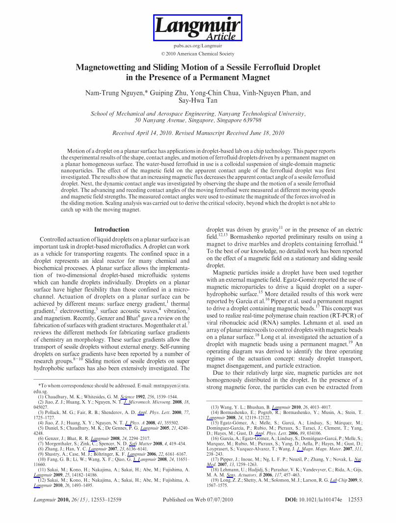
Experimental Setup. A permanent magnet was mounted onthe moving stage of a syringe pump (KD Scientific, USA). Thelinear motion of the syringe pump is programmable; thus, thevelocity of the permanentmagnet can be controlled.With the helpof a precision micrometer screw gauge, the top face of thepermanent magnet is positioned accurately at a distance of2 mm away from the hydrophobic surface. The Pyrex glasssubstrate is 0.5 mm thick. Thus, a gap of 1.5 mm between thelower surface of the glass slide and the top surface of the magnetwas maintained. For calibration purpose, a plastic ruler wasinserted into this gap. Three nickel-plated neodymium diskpermanent magnets of different dimensions and strengths werepurchased fromEclipseMagnetics (UnitedKingdom).Wedenotethem here as small (N700-RB,H= 4 mm,D= 2 mm), medium
Figure 1. Experimental setup: (a) Stationary and sliding ferrofluiddrop (only force components in x-axis are depicted). (b) Imagingsystem for both front view and side view of the droplet (not toscale).
(20) Nguyen, N. T.; Ng, K.M.; Huang, X. Y.Appl. Phys. Lett. 2006, 89, 052509.(21) Beyzavi, A.; Nguyen, N. T. J. Micromech. Microeng. 2010, 20, 015018.(22) Sun, Y.; Nguyen, N. T.; Kwok, Y. C. Anal. Chem. 2008, 80, 6127–6130.(23) Bormashenko, E.; Whyman, G. Chem. Phys. Lett. 2008, 463, 103–105.(24) Bormashenko, E. Colloids Surf., A 2009, 345, 163–165. (25) Hodges, S.; Jensen, O.; Rallison, J. J. Fluid Mech. 2007, 512, 95–131.
DOI: 10.1021/la101474e 12555Langmuir 2010, 26(15), 12553–12559
Nguyen et al. Article
(N701-RB, H = 2 mm, D = 3 mm), and large (N703-RB, H =6mm,D= 6mm) magnets. The heightH and the diameterD ofthe magnet are defined in Figure 1a. The magnetic flux density ofthe magnets on the glass surface wasmeasuredwith a commercialgaussmeter (GM04, measurement range of 0.1 to 299.9 mT, errorof (0.1 mT, Hirst Magnetics, United Kingdom). The measuredflux densities on the surface and along the magnet axis of thesmall, medium, and large magnets are 38( 0.1 mT, 64( 0.1 mT,and 199 ( 0.1 mT, respectively. These values are the averageddensity passing through the sensor area of the gaussmeter.Although the effect of the magnetic field is three-dimensional(or two-dimensional for our axis-symmetric case) and dependson the local flux density, the measured flux density is used hereas the indication of the field strength of the different magnets.The ferrofluid droplets were dispensed using a micropipet(Finnpipette, Thermo Scientific, United States). This micropipetcan dispense small volumes of liquid ranging from 0.5 to 10 μL.Droplets with different volumes were investigated. Since weintend to investigate the scaling relationship based on the basediameter of the droplet with a Bond number below unity, thevolumes are selected to have base diameters ranging from 1 mmto 3 mm. The droplets with different sizes are denoted as (I) to(V), Table 1.
Figure 1b shows the schematic setupof the imaging systemusedin the experiments reported in this paper. The images of theferrofluid droplet were captured by a CCD camera (Pulnix,progressive scan camera, JAI Inc., Japan). The camera software(Video Savant 3.0, IO Industries, Ontario, Canada) can record aseries of 149 image frames with a given frame rate. Since thesystem has a zoom objective, the size of the image frame can beadjusted accordingly. When the objective is zoomed out to itslimit, the largest error caused by pixel resolution is 30 μm. In eachexperiment, the frame rate was adjusted to match the velocity ofthe magnet (Table 2). The frames are stored as images or a singlemovie file. To observe the side view of the droplet, a 45� mirrorwas placed next to the droplet. With the mirror, the camera cancapture both top view and side view of the ferrofluid in a singleframe. As mentioned above, a plastic ruler was placed under theglass slide to give a reference for the later evaluation of thecaptured images. The shape of of the ferrofluid droplet wasmeasured automatically using a customizedMATLAB program.The program converts the recorded grayscale image into a binaryimage for further processing. In the stationary case, the image ofthe droplet was evaluated to extract parameters such as contactangle, base diameter, droplet height, and radius of curvature.The data were evaluated on the basis of ten recorded frames.The error is taken as the standard deviation of the collected data.
This random error is caused by the lighting condition and pixelresolution when the image is converted from grayscale format tobinary format. In the case of a moving droplet, the images wereprocessed to extract the droplet velocity and the advancing andthe receding contact angles. With the known frame rate, theseparameters can be plotted as functions of time. The propagationof systematic error from themeasurement of displacement and theframe rate can be estimated as follows:
Δv ¼�����
Δδxδt
�����þ�����
δx
δ2tΔδt
�����
ð1Þ
where Δν is the error of the evaluated velocity, δx is the displace-ment of the centroid of the droplet from one frame to the nextframe, δt is the time delay between two frames, Δδx is thesystematic error caused by camera resolution, and Δδt is thesystematic error caused by the timer of the frame grabber. For theworst-case estimation of the systematic error of the evaluatedvelocity, the displacement, the spacial error and the time error canbe estimated as δx= νδt,Δδx=0.03mm, andΔδt=10-6 s. Therelative systematic error of the velocity can then be calculated asε = Δν/ν � 100% and listed in Table 2 for the different velocityand frame rates used in our later experiments.
The contact angles were evaluated by first extracting thedroplet shape from the image. Next, a fifth-order polynomialwas fitted to the droplet shape. The derivative of the fittingpolynomial was calculated and used to determine the tangentand the corresponding contact angles at the two ends of thedroplet. Since the coefficients of the polynomialmay change in therecorded frames, it is difficult to derive a relative systematic errorfor the contact angles. In this paper, relative random error wasused for the contact angles. The random error was evaluated onthe basis of polynomial fitting lines of the data and plotted as aconfidenceband.The randomerror of the evaluated contact angleis about 4%. Because of smaller uncertainty in lighting conditionand grayscale to binary conversion, a stationary droplet has asmaller random error for the contact angles. Since the capillaryforce is evaluated on the basis of contact angle, the random errorpropagates to about 25%.
Results and Discussion
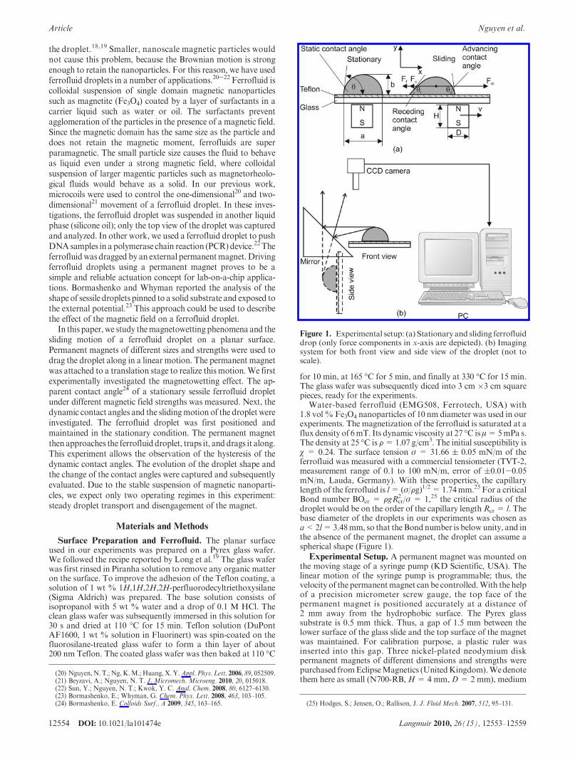
Magnetowetting. We first investigated the effect of magneticfield strength on the shape and contact angle of a sessile ferro-fluid droplet. This phenomenon is called magnetowetting here.Figure 2 shows the shape of droplet III under different magneticconditions. Without a permanent magnet, the droplet has a basediameter of 1.97 ( 0.10 mm and a contact angle of 72.4 ( 0.2�(Figure 2a). Under a magnetic field, the droplet is flattened andthe contact angle decreases (Figure 2b,c). With the flux density of199( 0.1 mT of the large magnet, the droplet takes the shape of apuddle (Figure 2d).
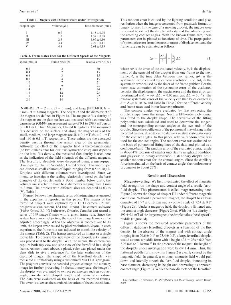
Figure 3 shows the measured geometric parameters of thedifferent stationary ferrofluid droplets as a function of the fluxdensity. In the absence of the magnet and with contact angleranging from 70.6( 0.1� to 73.4( 0.2�, a large ferrofluid dropletwould assume a puddle form with a height of b=2l sin θ/2 from3.28mm to 3.34mm.26 In the absence of themagnet, the height ofthe droplets under investigation were below 1.4 mm. Thus, theflattened puddle form shown in Figure 2 is clearly caused by themagnetic field. In general, a stronger magnetic field would pulldown and laterally stretch the ferrofluid droplet, increasing itsbase diameter, decreasing its height and decreasing its apparentcontact angle (Figure 3).While the base diameter of the ferrofluid
Table 1. Droplets with Different Sizes under Investigation
droplet type volume (μL) base diameter (mm)
I 0.7 1.15( 0.06II 1.3 1.57( 0.08III 2.3 1.97( 0.10IV 3.4 2.22( 0.11V 4.8 2.61( 0.13
Table 2. Frame Rates Used for the Different Speeds of the Magnets
speed (mm/s) frame rate (fps) relative error ε (%)
0.2 2 300.4 2 150.6 3 150.8 4 151.0 7 211.2 9 231.4 11 241.6 12 231.8 13 222.0 14 21
(26) Berthier, J.; Silberzan, P. Microfluidics and Biotechnology; Artech House,2009.
12556 DOI: 10.1021/la101474e Langmuir 2010, 26(15), 12553–12559
Article Nguyen et al.
droplet increases almost linearly with the flux density (Figure 3a),its height tends to reach an asymptotic value of about 0.6 mm(Figure 3b). The observed behavior is similar to that of a largedroplet with a large Bond number. In our case, themagnetic forceis a significant body force which can be 1 or 2 orders ofmagnitudehigher than gravitational force. Values extracted from the slidingexperiments support this hypothesis.
Sliding of a Sessile Ferrofluid Droplet. Droplet Kine-matics. In our experiments, three parameters were varied: threedifferent magnets (small, medium, and large), five different basediameters (Table 1), and ten different magnet velocities rangingfrom 0.2 to 2 mm/s. Two basic operating regimes were observed:sliding (Figure 4) and disengagement (Figure 5). The followinganalysis estimates the order of magnitude of the different forcesinvolved in the sliding process. These numbers will be used toestimate the scaling factors of the operating map discussed in thenext section.
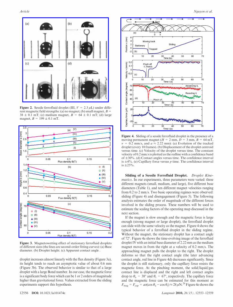
If the magnet is slow enough and the magnetic force is largeenough (strong magnet or large droplet), the ferrofluid dropletcan slide with the same velocity as the magnet. Figure 4 shows thetypical behavior of a ferrofluid droplet in the sliding regime.Without the magnet, the stationary droplet has a contact angleof 72�. Figure 4a shows the time-evolving image of the ferrofluiddroplet IVwith an initial base diameter of 2.22mmas themediummagnet moves in from the right at a velocity of 0.2 mm/s. Theapproaching magnet pulls the droplet to the right. The dropletdeforms so that the right contact angle (the later advancingcontact angle, red line in Figure 4d) decreases significantly. Sincethe droplet is still stationary, only the capillary force resists themagnetic force. At the pinching moment, the solid/liquid/gascontact line is displaced and the right and left contact anglesdrop to θa = 38� and θr = 67�, respectively. The capillary forceand the magnetic force can be estimated for this moment asFmag=Fcap= aσ(cos θa- cos θr)≈ 28μN.26 Figure 4e shows the
Figure 3. Magnetowetting effect of stationary ferrofluid dropletsof different sizes (the lines are second-order fitting curves): (a) Basediameter. (b) Droplet height. (c) Apparent contact angle .
Figure 2. Sessile ferrofluid droplet (III, V = 2.3 μL) under diffe-rentmagnetic field strengths: (a) nomagnet; (b) smallmagnet,B=38 ( 0.1 mT; (c) medium magnet, B = 64 ( 0.1 mT; (d) largemagnet, B= 199 ( 0.1 mT.
Figure 4. Sliding of a sessile ferrofluid droplet in the presence of amoving permanent magnet (H= 2 mm, D= 3 mm, B= 64 mT,ν = 0.2 mm/s, and a ≈ 2.22 mm): (a) Evolution of the trackeddroplet (every 10 frames). (b) Displacement of the droplet centroidversus time. (c) Velocity of the droplet versus time. The constantvelocity of 0.2mm/s is plotted as the redlinewith a confidence bandof(30%. (d) Contact angles versus time. The confidence intervalis (4%. (e) Capillary force versus p time. The confidence intervalis(25%.
DOI: 10.1021/la101474e 12557Langmuir 2010, 26(15), 12553–12559
Nguyen et al. Article
capillary force as a function of time. To appreciate the magnitudeof the magnetic force, the weight of the droplet calculated withthe given volume ofV= 3.4 μL and density of F= 1.07 g/cm3 is3.64 μN. From the pinching moment, the droplet accelerates to1.7 mm/s. After being trapped on the magnet, the dropletcontinues to deform and accelerates to the steady velocity of themagnet (Figure 4b). In this process, the relative distance betweenthe magnet and the droplet is adjusted to reach an equilibriumbetween capillary force, friction force, and magnetic force. Theevaluated velocity shows a wavy characteristics, which is causedby the stepper motor driving the linear stage. The advancingcontact angle then reaches a steady-state value of approximately64�, while the receding contact angle approaches a value ofapproximately 46�. The capillary force in the steady-state slidingmotion remains constant at a value of Fcap ≈ 18 μN (Figure 4e).
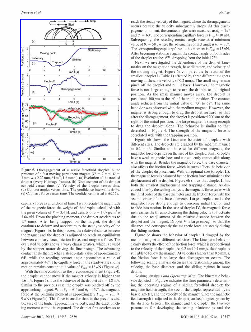
With the same condition as the previous experiment (Figure 4),the droplet cannot move if the magnet velocity is higher than1.6m/s. Figure 5 shows the behavior of the droplet at ν=1.8m/s.Similar to the previous case, the droplet was pinched off by theapproaching magnet. With θa = 61� and θr = 69�, the magneticforce at the pinching moment is approximately Fmag = Fcap ≈9 μN (Figure 5e). This force is smaller than in the previous casebecause of the higher approaching velocity, and the exact pinch-ing moment cannot be captured. The droplet first accelerates to
reach the steady velocity of the magnet, where the disengagementoccurs because the velocity subsequently drops. At this disen-gagement moment, the contact angles were measured as θa= 69�and θr = 60�. The corresponding capillary force is Fcap ≈ 10 μN.Subsequently, the receding contact angle reaches a minimumvalue of θr = 58�, where the advancing contact angle is θa = 70�.The corresponding capillary force at thismoment isFcap≈ 13 μN.After becoming stationary again, the contact angle on both sidesof the droplet reaches 67�, dropping from the initial 73�.
Next, we investigated the dependence of the droplet kine-matics on the magnetic strength, base diameter, and velocity ofthe moving magnet. Figure 6a compares the behavior of thesmallest droplet I (Table 1) affected by three different magnetsmoving at the same velocity of 0.2 mm/s. The small magnet canpinch off the droplet and pull it back. However, the magneticforce is not large enough to return the droplet to its originalposition. As the small magnet moves away, the droplet ispositioned 100 μm to the left of the initial position. The contactangle reduces from the initial value of 73� to 68�. The samebehavior was observed with the medium magnet. However, themagnet is strong enough to drag the droplet forward, so thatafter the disengagement, the droplet is positioned 200 μm to theright of the initial position. The large magnet is strong enoughto drag the droplet along. The behavior is similar to thatdescribed in Figure 4. The strength of the magnetic force iscorrelated well with the trapping position.
Figure 6b shows the kinematic behavior of droplets withdifferent sizes. The droplets are dragged by the medium magnetat 0.2 mm/s. Similar to the case for different magnets, themagnetic force depends on the size of the droplet. Small dropletshave a weak magnetic force and consequently cannot slide alongwith the magnet. Besides the magnetic force, the base diameteralso affects the friction force, which in turns affects the behaviorof the droplet displacement. With an optimal size (droplet II),themagnetic force is balanced by the friction forceminimizing thedisplacement of the droplet. Figure 6b shows that droplet II hasboth the smallest displacement and trapping distance. As dis-cussed later by the scaling analysis, the magnetic force scales withthe third order of the base diameter and the friction force with thesecond order of the base diameter. Large droplets make themagnetic force strong enough to overcome initial friction andto slide into motion. In the case of droplet IV, the magnetic forcejust reaches the threshold causing the sliding velocity to fluctuatedue to the readjustment of the relative distance between thedroplet and the magnet. Droplet V is large enough so that thedistance and consequently the magnetic force are steady duringthe sliding motion.
Figure 6c shows the behavior of droplet II dragged by themedium magnet at different velocities. The kinematic behaviorclearly shows the effect of the friction force, which is proportionalto the velocity of the droplet. At 0.2 and 0.4 mm/s, the droplet isstill able to follow themagnet. At velocities higher than 0.6 mm/s,the friction force is so large that disengagement occurs. Thefollowing scaling analysis discusses the relationship among thevelocity, the base diameter, and the sliding regimes in moredetails.
Scaling Analysis and Operating Map. The kinematic beha-vior depicted in Figure 6 indicates the three parameters determin-ing the operating regime of a sliding ferrofluid droplet: themagnetic field strength, the size of the droplet represented by itsbase diameter, and the velocity of the magnet. Since the magneticfield strength is adjusted in the droplet/surface/magnet system bythe distance between the magnet and the droplet, the two keyparameters for developing the scaling relationships and the
Figure 5. Disengagement of a sessile ferrofluid droplet in thepresence of a fast moving permanent magnet (H = 2 mm, D =3mm, a≈ 2.22mm, 64mT, 1.8mm/s): (a) Evolution of the trackeddroplet (every 10 image frames). (b) Displacement of the dropletcentroid versus time. (c) Velocity of the droplet versus time.(d) Contact angles versus time. The confidence interval is (4%.(e) Capillary force versus time. The confidence interval is(25%.

12558 DOI: 10.1021/la101474e Langmuir 2010, 26(15), 12553–12559
Article Nguyen et al.
operating map for the sliding ferrofluid droplet are the basediameter a and the magnet velocity ν.
As shown in Figure 1a, the force balance in the x-axis of asliding ferrofluid droplet is
Fmag ¼ FfricþFcap ð2Þwhere Fmag is the driving magnetic force, Ffric is the friction force,and Fcap is the capillary force caused by the difference betweenadvancing and receding contact angles.
The magnetic force is determined by
Fmag ¼ Vχ
μ0BrB ¼ Ra3 ð3Þ
where V � a3 is the volume of the droplet, χ is the magneticsusceptibility of the ferrofluid, μ0 is the permittivity of free space,and B is the magnetic field applied on the droplet. With a fixedrelative position between the droplet and the magnet, factor Rrepresents the strength of the magnetic field. The scaling relation-ship of the magnetic force is F � a3.
The friction force acting against the sliding motion of thedroplet can be estimated as
Ffric ¼ KfAμv ¼ βa2v ð4Þwhere Kf is the friction factor, A= πa2/4 is the contact area, μ isthe viscosity of the ferrofluid, and ν is the velocity of the magnetand the droplet. The above relationship considers the flattenedshape of the droplet due to the strong magnetic pull, where thefactorKf is assumed to be constant. The scaling relationship of thefriction force is Ffric � a2. The factor β represents the frictionbetween the droplet and the solid surface.
The capillary force acting against the sliding motion is
Fcap ¼ aσðcos θr - cos θaÞ ¼ γa ð5Þwhere σ is the surface tension of the ferrofluid. Since the advan-cing and receding contact angles θa, θr remains constant in thesteady-state sliding condition,The factorγ represents the strengthof capillarity. The scaling relationship of the capillary force isFfric � a.
The droplet can slide if a critical velocity νcr is reached. Theforce balance has the form
Ra3 ¼ βa2vcr þ γa ð6ÞRearranging the above equation leads to the scaling relationshipbetween the critical velocity and the base diameter of the droplet
vcr ¼ Rβa-
γ
β
1
að7Þ
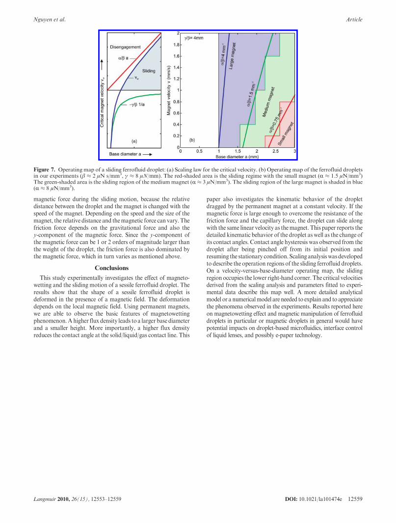
Figure 7a depicts the two terms forming the curve of the criticalvelocity on the velocity/base diameter operatingmap. The shadedarea to the right of the curve represents the sliding regime. In thisregion, themagnetic force is large enough to overcome the frictionand to drag the droplet along. A low velocity and a large dropletwould make sliding possible. Therefore, the sliding region occu-pies the lower right-hand corner of the operating map. Figure 7bshows the operating map observed in our experiments. The red,green, and blue-shaded areas are the sliding regions of the smallmagnet, medium magnet, and large magnet, respectively.
The parameters R, β, and γ from the scaling analysis were usedto fit the experimental data. To start with, we used data of themedium magnet and droplet IV (Figure 4) due to the relativelylow noise of the data of the capillary force. The maximumcapillary force of the pinch-off moment of 28 μN is used toestimate themagnetic force. Fromeq3 and a=2.22mm, the scal-ing factor for the magnetic force is determined as R≈ 3 μN/mm3.From eq 5 and a capillary force during the sliding motion ofFcap ≈ 18 μN, the scaling factor for the capillary force isdetermined as γ = 8 μN/mm. Since there is no further informa-tion for the estimation of the friction force, the values of R and βwere used to find β=2 μN s/mm3 so that the curve of eq 7 can fitthe experimental data of the medium magnet, Figure 7b. Subse-quently, the values ofγ=8 μN/mmand β=2 μNs/mm3 and eq 7were used to findR≈ 1.5 μN/mm3 and R≈ 8 μN/mm3 that can fitthe data of the small and the large magnet, respectively.
The above scaling analysis and fitting scaling factors onlyqualitatively explain the interactions among the forces involved inthe sliding motion. In fact, only the magnitude of the capillaryforce can be extracted from the measurement. The magneticforce at the pinch-off moment is not necessarily the same as the
Figure 6. Dependence of droplet kinematics on different parameters: (a)Magnetic strength (droplet I,magnet velocity of 0.2mm/s). (b) Basediameter of droplet (medium magnet, magnet velocity of 0.2 mm/s). (c) Velocity of the magnet (medium magnet, droplet II).
DOI: 10.1021/la101474e 12559Langmuir 2010, 26(15), 12553–12559
Nguyen et al. Article
magnetic force during the sliding motion, because the relativedistance between the droplet and the magnet is changed with thespeed of the magnet. Depending on the speed and the size of themagnet, the relative distance and themagnetic force can vary. Thefriction force depends on the gravitational force and also they-component of the magnetic force. Since the y-component ofthe magnetic force can be 1 or 2 orders of magnitude larger thanthe weight of the droplet, the friction force is also dominated bythe magnetic force, which in turn varies as mentioned above.
Conclusions
This study experimentally investigates the effect of magneto-wetting and the sliding motion of a sessile ferrofluid droplet. Theresults show that the shape of a sessile ferrofluid droplet isdeformed in the presence of a magnetic field. The deformationdepends on the local magnetic field. Using permanent magnets,we are able to observe the basic features of magnetowettingphenomenon.Ahigher flux density leads to a larger base diameterand a smaller height. More importantly, a higher flux densityreduces the contact angle at the solid/liquid/gas contact line. This
paper also investigates the kinematic behavior of the dropletdragged by the permanent magnet at a constant velocity. If themagnetic force is large enough to overcome the resistance of thefriction force and the capillary force, the droplet can slide alongwith the same linear velocity as themagnet. This paper reports thedetailed kinematic behavior of the droplet as well as the change ofits contact angles. Contact angle hysteresis was observed from thedroplet after being pinched off from its initial position andresuming the stationary condition. Scaling analysis was developedto describe the operation regions of the sliding ferrofluid droplets.On a velocity-versus-base-diameter operating map, the slidingregion occupies the lower right-hand corner. The critical velocitiesderived from the scaling analysis and parameters fitted to experi-mental data describe this map well. A more detailed analyticalmodel or a numericalmodel are needed to explain and to appreciatethe phenomena observed in the experiments. Results reported hereon magnetowetting effect and magnetic manipulation of ferrofluiddroplets in particular or magnetic droplets in general would havepotential impacts on droplet-based microfluidics, interface controlof liquid lenses, and possibly e-paper technology.
Figure 7. Operating map of a sliding ferrofluid droplet: (a) Scaling law for the critical velocity. (b) Operating map of the ferrofluid dropletsin our experiments (β ≈ 2 μN s/mm3, γ ≈ 8 μN/mm). The red-shaded area is the sliding regime with the small magnet (R ≈ 1.5 μN/mm3)The green-shaded area is the sliding region of the mediummagnet (R≈ 3 μN/mm3). The sliding region of the large magnet is shaded in blue(R ≈ 8 μN/mm3).