mahalakshmimahalakshmiengineeringcollege.com/pdf/ece/iiisem/ec2201/unit 1.pdfwinding in a d.c....
TRANSCRIPT

R.Thiyagarajan Page 1
MAHALAKSHMI
ENGINEERING COLLEGE
TIRUCHIRAPALLI- 621213.
QUESTION BANK
DEPARTMENT: ECE SEMESTER – III
SUBJECT CODE: EC2201 SUBJECT NAME: Electrical Engineering
UNIT 1
D.C MACHINES
PART – A
1. Why series cannot be started without any load? [NOV/DEC 2007]
In dc series motor, flux is directly proportional to armature current. i.e., Ф α Ia.
Under no load condition, the armature current is very low and flux also is less. By
using the formula N α 1/ Ф, here Ф is less; the motor speed will be very high. Due
to this motor will be damaged. Hence DC series motor should always be started
some load on the shaft.
2. Define the term “Speed regulation” of a DC motor? [NOV/DEC 2007]
eedFullloadsp
eedFullloadspNoloadspedationSpeedregul
3. What are the applications of DC motors? [APR/MAY 2007]
The application of Motors mainly looks at three aspects of operation.
1. Starting
2. Speed control
3. Braking
Shunt motors may be used for driving centrifugal pumps and light machine tools,
wood working machines, Laths etc.,
R.Thiyagarajan Page 2
Series motors are ideal for use in electric trains, cranes, hoists, lifts, blowers,
conveyers etc.
Compound motors are used for driving heavy machine tools intermittent loads
shears, punching machines etc.,
4. Mention the types of braking of dc motor? [APR/MAY 2007]
1. Regenerative braking
2. Dynamic braking
3. Plugging
5. What are the losses in dc motor? [NOV/DEC 2007]
1. Copper losses
2. Iron losses
3. Mechanical losses
6. Name any 2 non – loading methods of testing dc machines. [MAY/JUNE 2007]
1. Swinburnes’s test 2. Hopkinson test
7. What are the essential parts of a d.c generator? [APRIL/MAY 2008]
1. Magnetic frame or yoke 2. Poles 3. Armature 4. Commutator, pole shoes,
armature windings, interpoles 5. Brushes, bearings and shaft.
8. What are the different methods of excitation of D.C generator? [APRIL/MAY
2008]
1. Separate excitation
2. Self excitation
9.What are the functions of yoke in a D.C machines? [ NOV,DEC 2009 ]
The magnetic frame or yoke serves two purposes.
1. It acts as a protecting cover for the whole machine and provides mechanical
support for the poles.

R.Thiyagarajan Page 3
2. It carries magnetic flux produced by the poles.
10. List the methods of speed control of a D.C. shunt motor. [NOV, DEC 2009]
1. Armature control
2. Flux or field control
3. Applied voltage control
11. Write the e.m.f equation of a generator. [NOV/DEC 2009]
Eg= (PФZN/60A) Volts.
p-------- No of poles
Z -------- Total no of conductor
Ф-------- Flux per pole
N-------- Speed in rpm.
12. What are the types of armature winding? [APRIL/MAY 2009]
1. Lap winding, A=P,
2. Wave winding, A=2.
13. What is back emf in d.c. motor? [APRIL/MAY 2009] [NOV/DEC 2012]
As the motor armature rotates, the system of conductor come across alternate north
and South Pole magnetic fields causing an emf induced in the conductors. The
direction of the emf induced in the conductor is in opposite to current. As this emf
always opposes the flow of current in motor operation it is called as back emf.
A
PX
ZNEb
60

R.Thiyagarajan Page 4
14. What are the different types DC generators? [APRIL/MAY 2009]
According to the way in which their fields are excited, generators are classified into:
1. Separately excited D.C. Generator 2. Self excited D.C. Generators
i) Shunt Generator
ii) Series Generator
iii) Compound Generator
15. What is a dc compound generator? [NOV/DEC 2010]
The compound generator consist of both shunt field and series field windings. One
winding is in series and other winding is in parallel with armature. Depending
upon the shunt field and series field connections, compound generator can be
classified as
1. Long shunt compound generator 2. Short shunt compound generator
16. What is the need for starter in dc motor? [NOV/DEC 2010]
When a dc motor is directly switched on, at the time of starting, the motor back emf is
zero. Due to this, the armature current is very high. Due to the very high current, the
motor gets damaged. To reduce the starting current of the motor a starter is used. 8.
17. What is meant by self excited generator? [APRIL/MAY 2010]
I n D.C generator field winding is supplied from the armature of the generator
itself, then it is called a self – excited d.c generator.
18. State faraday’s laws of electromagnetic induction. [NOV/DEC 2011]
Faraday’s laws of electromagnetic induction, States that whenever conductor is
moved in a magnetic field, dynamically induced emf produced in the conductor.
19. State the principle of working of D.C motor. [NOV/DEC 2011]

R.Thiyagarajan Page 5
The basic principle of operation of D.C motor is that, when a current carrying
conductor is placed in a magnetic field it experiences a force tending to move it.
20. Draw the OCC curve of self – excited generator. [NOV/DEC 2011]
21. Specify the role of commutator in D.C generator? [MAY/JUNE 2011]
Conduct electricity between rotating armature and fixed brushes, convert
alternating emf into unidirectional emf (mechanical rectifier).
22. What are the applications of DC motors? [MAY/JUNE 2011]
1. DC shunt Generator
The terminal voltage of DC shunt generator is more or less constant from no load
to full load .Therefore these generators are used where constant voltage is required.
For electro plating
Battery charging
For excitation of Alternators.
2. Series Generators:
The terminal voltage of series generator increases with load current from no load to
full load .Therefore these generators are,

R.Thiyagarajan Page 6
Used as Boosters
Used for supply to arc Lamps
3. Compound Generator:
Differential Compound generators are used to supply dc welding machines.
Level compound generators are used to supply power for offices, hostels and
Lodges etc.
23. Define critical field resistance of dc shunt generator?
Critical field resistance is defined as the resistance of the field circuit which will
cause the shunt generator just to build up its emf at a specified field.
24. What is eddy current loss?
When a magnetic core carries a time varying flux, voltages are induced in all
possible path enclosing flux. Resulting is the production of circulating flux in core.
These circulating current do no useful work are known as eddy current and have
power loss known as eddy current loss.
25. How hysteresis and eddy current losses are minimized?
Hysteresis loss can be minimized by selecting materials for core such as silicon
steel & steel alloys with low hysteresis co-efficient and electrical resistivity. Eddy
current losses are minimized by laminating the core.
26. What is the function of no-voltage release coil in d.c. motor starter?
As long as the supply voltage is on healthy condition the current through the NVR
coil produce enough magnetic force of attraction and retain the starter handle in
ON position against spring force. When the supply voltage fails or becomes lower
than a prescribed value then electromagnet may not have enough force to retain so
handle will come back to OFF position due to spring force automatically.

R.Thiyagarajan Page 7
PART – B
1. (a) (I) With neat sketch explain the constructional details of a D.C machine.
[NOV/DEC 2009] [NOV/DEC 2010] [NOV/DEC 2012]
1.4 Construction of d.c. Generator
The d.c. generators and d.c. motors have the same general construction. In
fact, when the machine is being assembled, the workmen usually do not know
whether it is a d.c. generator or motor. Any d.c. generator can be run as a d.c.
motor and vice-versa. All d.c. machines have five principal components viz., (i)
field system (ii) armature core (iii) armature winding (iv) commutator (v) Brushes
Fig: Cross sectional view of D.C machine
(i) Field system
The function of the field system is to produce uniform magnetic field within
which the armature rotates. It consists of a number of salient poles (of course, even
number) bolted to the inside of circular frame (generally called yoke). The yoke is
usually made of solid cast steel whereas the pole pieces are composed of stacked
laminations. Field coils are mounted on the poles and carry the d.c. exciting
current. The field coils are connected in such a way that adjacent poles have
opposite polarity.
R.Thiyagarajan Page 8
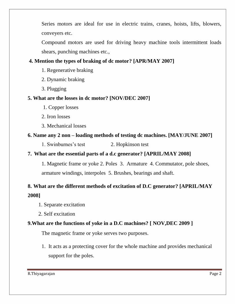
The m.m.f. developed by the field coils produces a magnetic flux that passes
through the pole pieces, the air gap, the armature and the frame .
Fig: Cross sectional view of field system
Practical d.c. machines have air gaps ranging from 0.5 mm to 1.5 mm. Since
armature and field systems are composed of materials that have high permeability,
most of the m.m.f. of field coils is required to set up flux in the air gap. By
reducing the length of air gap, we can reduce the size of field coils (i.e. number of
turns).
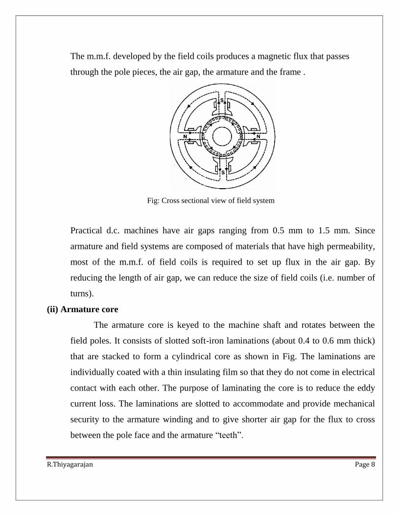
(ii) Armature core
The armature core is keyed to the machine shaft and rotates between the
field poles. It consists of slotted soft-iron laminations (about 0.4 to 0.6 mm thick)
that are stacked to form a cylindrical core as shown in Fig. The laminations are
individually coated with a thin insulating film so that they do not come in electrical
contact with each other. The purpose of laminating the core is to reduce the eddy
current loss. The laminations are slotted to accommodate and provide mechanical
security to the armature winding and to give shorter air gap for the flux to cross
between the pole face and the armature “teeth”.

R.Thiyagarajan Page 9
Fig: cylindrical core
(iii) Armature winding
The slots of the armature core hold insulated conductors that are connected
in a suitable manner. This is known as armature winding. This is the winding in
which “working” e.m.f. is induced. The armature conductors are connected
inseries-parallel; the conductors being connected in series so as to increase the
voltage and in parallel paths so as to increase the current. The armature winding of
a d.c. machine is a closed-circuit winding; the conductors being connected in a
symmetrical manner forming a closed loop or series of closed loops.
(iv) Commutator
A commutator is a mechanical rectifier which converts the alternating
voltage generated in the armature winding into direct voltage across the brushes.
The commutator is made of copper segments insulated from each other by mica
sheets and mounted on the shaft of the machine. The armature conductors are
soldered to the commutator segments in a suitable manner to give rise to the
armature winding. Depending upon the manner in which the armature conductors
are connected to the commutator segments, there are two types of armature
winding in a d.c. machine viz., (a) lap winding (b) wave winding. Great care is
taken in building the commutator because any eccentricity will cause the brushes

R.Thiyagarajan Page 10
to bounce, producing unacceptable sparking. The sparks may burn the brushes and
overheat and carbonise the commutator.
Fig: Commutator
(v) Brushes
The purpose of brushes is to ensure electrical connections between the
rotating commutator and stationary external load circuit. The brushes are made of
carbon and rest on the commutator. The brush pressure is adjusted by means of
adjustable springs. If the brush pressure is very large, the friction produces heating
of the commutator and the brushes. On the other hand, if it is too weak, the
imperfect contact with the commutator may produce sparking. Multipole machines
have as many brushes as they have poles. For example, a 4- pole machine has 4
brushes. As we go round the commutator, the successive brushes have positive and
negative polarities. Brushes having the same polarity are connected together so that
we have two terminals viz., the +ve terminal and the -ve terminal
1. (b) (i) Draw and explain the internal and external characteristics of a D.C shunt
generator. [NOV/DEC 2009]
R.Thiyagarajan Page 11
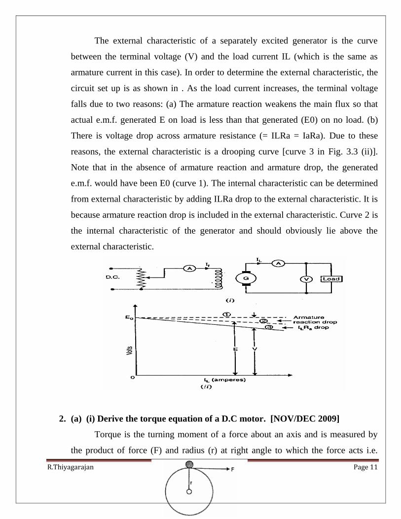
The external characteristic of a separately excited generator is the curve
between the terminal voltage (V) and the load current IL (which is the same as
armature current in this case). In order to determine the external characteristic, the
circuit set up is as shown in . As the load current increases, the terminal voltage
falls due to two reasons: (a) The armature reaction weakens the main flux so that
actual e.m.f. generated E on load is less than that generated (E0) on no load. (b)
There is voltage drop across armature resistance (= ILRa = IaRa). Due to these
reasons, the external characteristic is a drooping curve [curve 3 in Fig. 3.3 (ii)].
Note that in the absence of armature reaction and armature drop, the generated
e.m.f. would have been E0 (curve 1). The internal characteristic can be determined
from external characteristic by adding ILRa drop to the external characteristic. It is
because armature reaction drop is included in the external characteristic. Curve 2 is
the internal characteristic of the generator and should obviously lie above the
external characteristic.
2. (a) (i) Derive the torque equation of a D.C motor. [NOV/DEC 2009]
Torque is the turning moment of a force about an axis and is measured by
the product of force (F) and radius (r) at right angle to which the force acts i.e.

R.Thiyagarajan Page 12
D.C. Motors T = F x
circumferential force F at a distance r, the radius of the armature (Fig. 4.8).
Therefore, each conductor exerts a torque, tending to rotate the armature. The sum
of the torques due to all armature conductors is known as gross or armature torque
(Ta).
Let in a d.c. motor
r = average radius of armature in m
m
Z = total number of armature conductors
A = number of parallel paths
i = current in each conductor = Ia/A
B = average flux density in Wb/m2
P = number of poles
Force on each conductor, F = B i l newtons

R.Thiyagarajan Page 13
2 (b) (ii) With a neat sketch explain the operation of a three point starter for
a D.C motor.[NOV/DEC 2009]
R.Thiyagarajan Page 14
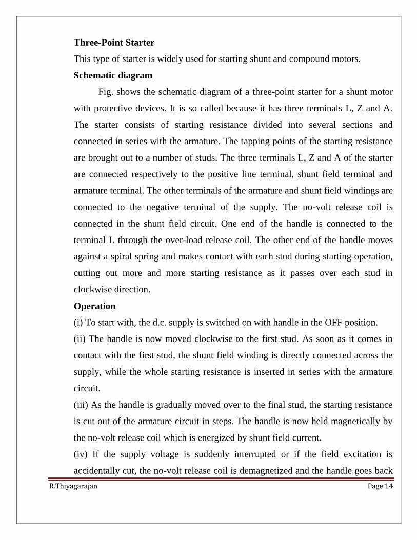
Three-Point Starter
This type of starter is widely used for starting shunt and compound motors.
Schematic diagram
Fig. shows the schematic diagram of a three-point starter for a shunt motor
with protective devices. It is so called because it has three terminals L, Z and A.
The starter consists of starting resistance divided into several sections and
connected in series with the armature. The tapping points of the starting resistance
are brought out to a number of studs. The three terminals L, Z and A of the starter
are connected respectively to the positive line terminal, shunt field terminal and
armature terminal. The other terminals of the armature and shunt field windings are
connected to the negative terminal of the supply. The no-volt release coil is
connected in the shunt field circuit. One end of the handle is connected to the
terminal L through the over-load release coil. The other end of the handle moves
against a spiral spring and makes contact with each stud during starting operation,
cutting out more and more starting resistance as it passes over each stud in
clockwise direction.
Operation
(i) To start with, the d.c. supply is switched on with handle in the OFF position.
(ii) The handle is now moved clockwise to the first stud. As soon as it comes in
contact with the first stud, the shunt field winding is directly connected across the
supply, while the whole starting resistance is inserted in series with the armature
circuit.
(iii) As the handle is gradually moved over to the final stud, the starting resistance
is cut out of the armature circuit in steps. The handle is now held magnetically by
the no-volt release coil which is energized by shunt field current.
(iv) If the supply voltage is suddenly interrupted or if the field excitation is
accidentally cut, the no-volt release coil is demagnetized and the handle goes back
R.Thiyagarajan Page 15
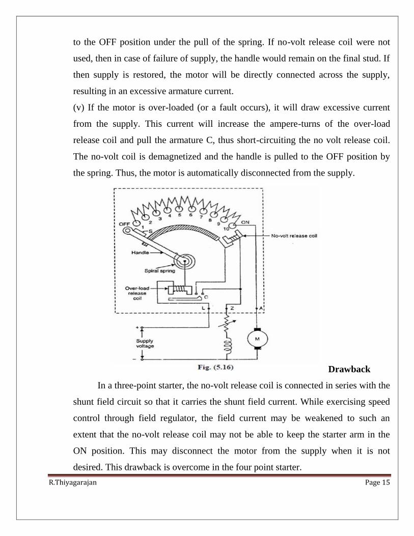
to the OFF position under the pull of the spring. If no-volt release coil were not
used, then in case of failure of supply, the handle would remain on the final stud. If
then supply is restored, the motor will be directly connected across the supply,
resulting in an excessive armature current.
(v) If the motor is over-loaded (or a fault occurs), it will draw excessive current
from the supply. This current will increase the ampere-turns of the over-load
release coil and pull the armature C, thus short-circuiting the no volt release coil.
The no-volt coil is demagnetized and the handle is pulled to the OFF position by
the spring. Thus, the motor is automatically disconnected from the supply.
Drawback
In a three-point starter, the no-volt release coil is connected in series with the
shunt field circuit so that it carries the shunt field current. While exercising speed
control through field regulator, the field current may be weakened to such an
extent that the no-volt release coil may not be able to keep the starter arm in the
ON position. This may disconnect the motor from the supply when it is not
desired. This drawback is overcome in the four point starter.
R.Thiyagarajan Page 16
3. (a) Draw and explain the no load and load characteristics of DC shunt
generator. [NOV/DEC 2007]
No load Characteristics of a shunt generator
Field coil (F1, F2) along with a series external resistance is connected in
parallel with the armature terminals (A1, A2) of the machine as shown in figure.
Let us first qualitatively explain how such connection can produce sufficient
voltage. Suppose there exists some residual field. Therefore, if the generator is
driven at rated speed, we should expect a small voltage (resknφ to be induced
across the armature. But this small voltage will be directly applied across the field
circuit since it is connected in parallel with the armature. Hence a small field
current flows producing additional flux. If it so happens that this additional flux
aids the already existing residual flux, total flux now becomes more generating
more voltage. This more voltage will drive more field current generating more
voltage. Both field current and armature generated voltage grow cumulatively.
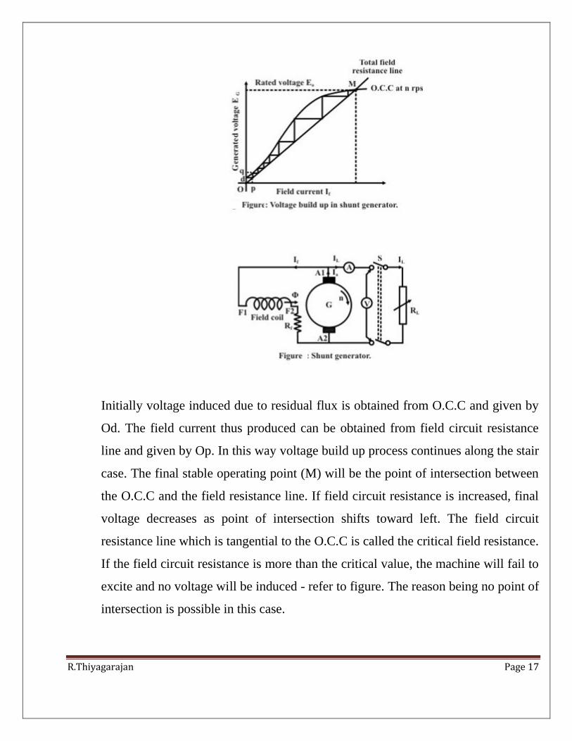
This growth of voltage and the final value to which it will settle down can be
understood by referring to (where two plots have been shown. One corresponds to
the O.C.C at rated speed and obtained by connecting the generator in separately
excited fashion as detailed in the preceding section. The other one is the V-I
characteristic of the field circuit which is a straight line passing through origin and
its slope represents the total field circuit resistance.
R.Thiyagarajan Page 17
Initially voltage induced due to residual flux is obtained from O.C.C and given by
Od. The field current thus produced can be obtained from field circuit resistance
line and given by Op. In this way voltage build up process continues along the stair
case. The final stable operating point (M) will be the point of intersection between
the O.C.C and the field resistance line. If field circuit resistance is increased, final
voltage decreases as point of intersection shifts toward left. The field circuit
resistance line which is tangential to the O.C.C is called the critical field resistance.
If the field circuit resistance is more than the critical value, the machine will fail to
excite and no voltage will be induced - refer to figure. The reason being no point of
intersection is possible in this case.
R.Thiyagarajan Page 18
Suppose a shunt generator has built up voltage at a certain speed. Now if the speed
of the prime mover is reduced without changing Rf, the developed voltage will be
less as because the O.C.C at lower speed will come down (refer to figure 38.8). If
speed is further reduced to a certain critical speed (ncr), the present field resistance
line will become tangential to the O.C.C at ncr. For any speed below ncr, no
voltage built up is possible in a shunt generator.
Load characteristic of shunt generator
With switch S in open condition, the generator is practically under no load
condition as field current is pretty small. The voltmeter reading will be Eo as
shown in figures (38.5) and (38.6). In other words, Eo and Ia = 0 is the first point
in the load characteristic. To load the machine S is closed and the load resistances
decreased so that it delivers load current IL. Unlike separately as well. The drop in
the terminal voltage will be caused by the usual Irdrop, brush voltage drop and
armature reaction effect. Apart from these, in shunt generator, as terminal voltage
decreases, field current hence excited motor, here IL ≠ Ia. In fact, for shunt
generator, Ia = IL - If. So increase of IL will mean increase of Ia aa φ also
decreases causing additional drop in terminal voltage. Remember in shunt
generator, field current is decided by the terminal voltage by virtue of its parallel
connection with the armature. Figure (38.9) shows the plot of terminal voltage
versus armature current which is called the load characteristic.
One can of course translate the V versus Ia characteristic into V versus IL
characteristic by subtracting the correct value of the field current from the armature
current. For example, suppose the machine is loaded such that terminal voltage
becomes V1 and the armature current is Ia1. The field current at this load can be
read from the field resistance line corresponding to the existing voltage V1 across

R.Thiyagarajan Page 19
the field as shown in figure (38.9). Suppose If1 is the noted field current.
Therefore, ILl = Ia1- If1.Thus the point [Ia1, V1] is translated into [ILl, V1] point.
Repeating these step for all the points we can get the V versus IL characteristic as
well. It is interesting to note that the generated voltage at this loading is EG1
(obtained from OCC corresponding to If1). Therefore the length PQ must
represents sum of all the voltage drops that has taken place in the armature when it
delivers Ia.
(b) Derive the emf equation of DC generator.[NOV/DEC 2007] [NOV/DEC
2012]
We shall now derive an expression for the e.m.f. generated in a d.c.
generator.
Let
Z = total number of armature conductors
P = number of poles
A = number of parallel paths = 2 ... for wave winding
= P ... for lap winding
N = speed of armature in r.p.m.
Eg = e.m.f. of the generator = e.m.f./parallel path

R.Thiyagarajan Page 20
Flux cut by one conductor in one revolutio
Time taken to complete one revolution, dt = 60/N second
4. (a) Draw and explain the characteristics of DC series generator with neat
sketch. [APR/MAY 2010]
Characteristics Series of DC generator:
Fig. shows the connections of a series wound generator. Since there is only
one current (that which flows through the whole machine), the load current is the
same as the exciting current.
(i)O.C.C.
Curve 1 shows the open circuit characteristic (O.C.C.) of a series generator.
It can be obtained experimentally by disconnecting the field winding from the
machine and exciting it from a separate d.c. source.
(ii) Internal characteristic

R.Thiyagarajan Page 21
Curve 2 shows the total or internal characteristic of a series generator. It
gives the relation between the generated e.m.f. E. on load and armature current.
Due to armature reaction, the flux in the machine will be less than the flux at no
load. Hence, e.m.f. E generated under load conditions will be less than the e.m.f.
EO generated under no load conditions. Consequently, internal characteristic curve
generated under no load conditions. Consequently, internal characteristic curve lies
below the O.C.C. curve; the difference between them representing the effect of
armature reaction
(iii) External characteristic
Curve 3 shows the external characteristic of a series generator. It gives the
relation between terminal voltage and load current IL.
4. (b) Explain the speed control methods used in D.C shunt motor. [APR/MAY
2010] .[NOV/DEC 2012]
Speed Control of D.C. Shunt Motors
The speed of a shunt motor can be changed by
(i) flux control method
(ii) Armature control method
(iii) Voltage control method.
The first method (i.e. flux control method) is frequently used because it is
simple and inexpensive.
1. Flux control method
can be changed and hence the name flux control method. In this method, a variable
resistance (known as shunt field rheostat) is placed in series with shunt field
winding as shown in Fig. (5.1).

R.Thiyagarajan Page 22
Therefore, we can only raise the speed of the motor above the normal speed (See
Fig. 5.2). Generally, this method permits to increase the speed in the ratio 3:1.
Wider speed ranges tend to produce instability and poor commutation.
Advantages
(i) This is an easy and convenient method.
(ii) It is an inexpensive method since very little power is wasted in the shunt field
rheostat due to relatively small value of Ish.
(iii) The speed control exercised by this method is independent of load on the
machine.
Disadvantages
i) Only speeds higher than the normal speed can be obtained since the total field
circuit resistance cannot be reduced below Rsh—the shunt field winding
resistance.
(ii) There is a limit to the maximum speed obtainable by this method. It is because
if the flux is too much weakened, commutation becomes poorer.
Note. The field of a shunt motor in operation should never be opened because its
speed will increase to an extremely high value.
2. Armature control method
This method is based on the fact that by varying the voltage available across
the armature, the back e.m.f and hence the speed of the motor can be changed. This

R.Thiyagarajan Page 23
is done by inserting a variable resistance RC (known as controller resistance) in
series with the armature as shown in Fig. (5.3).
where RC = controller resistance
Due to voltage drop in the controller resistance, the back e.m.f. (Eb) is
decreased. Since N µ Eb, the speed of the motor is reduced. The highest speed
obtainable is that corresponding to RC = 0 i.e., normal speed. Hence, this method
can only provide speeds below the normal speed (See Fig. 5.4).
Disadvantages
(i) A large amount of power is wasted in the controller resistance since it carries
full armature current Ia.
(ii) The speed varies widely with load since the speed depends upon the voltage
drop in the controller resistance and hence on the armature current demanded by
the load.
(iii) The output and efficiency of the motor are reduced.
(iv) This method results in poor speed regulation.
Due to above disadvantages, this method is seldom used to control the speed of
shunt motors.

R.Thiyagarajan Page 24
Note. The armature control method is a very common method for the speed control
of d.c. series motors. The disadvantage of poor speed regulation is not important in
a series motor which is used only where varying speed service is required.
3. Voltage control method
In this method, the voltage source supplying the field current is different
from that which supplies the armature. This method avoids the disadvantages of
poorspeed regulation and low efficiency as in armature control method. However,
it is quite expensive. Therefore, this method of speed control is employed for large
size motors where efficiency is of great importance.
Multiple voltage control.
In this method, the shunt field of the motor is connected permanently across
a-fixed voltage source. The armature can be connected across several different
voltages through a suitable switchgear. In this way, voltage applied across the
armature can be changed. The speed will be approximately proportional to the
voltage applied across the armature. Intermediate speeds can be obtained by means
of a shunt field regulator.
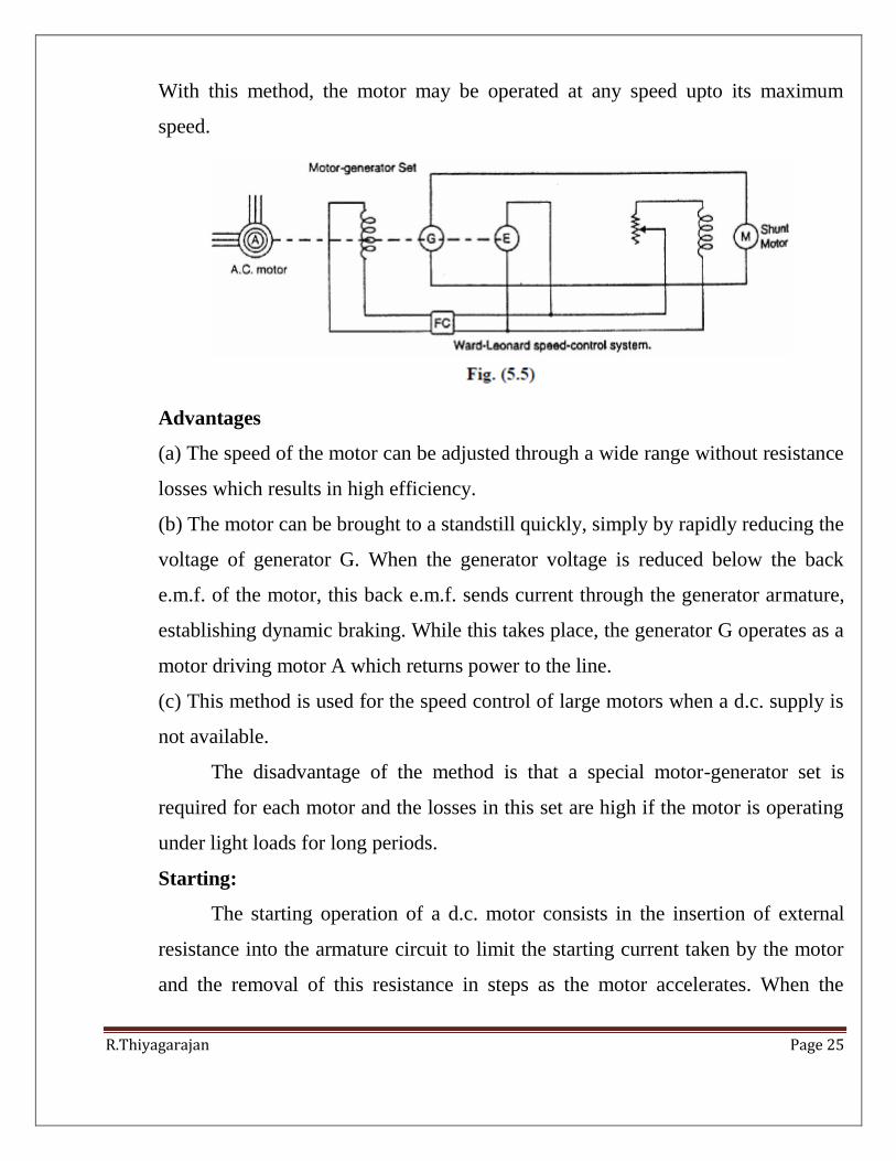
Ward-Leonard system.
In this method, the adjustable voltage for the armature is obtained from an
adjustable-voltage generator while the field circuit is supplied from a separate
source. This is illustrated in Fig. (5.5). The armature of the shunt motor M (whose
speed is to be controlled) is connected directly to a d.c. generator G driven by a
constant-speed a.c. motor A. The field of the shunt motor is supplied from a
constant-voltage exciter E. The field of the generator G is also supplied from the
exciter E. The voltage of the generator G can be varied by means of its field
regulator. By reversing the field current of generator G by controller FC, the
voltage applied to the motor may be reversed. Sometimes, a field regulator is
included in the field circuit of shunt motor M for additional speed adjustment.
R.Thiyagarajan Page 25
With this method, the motor may be operated at any speed upto its maximum
speed.
Advantages
(a) The speed of the motor can be adjusted through a wide range without resistance
losses which results in high efficiency.
(b) The motor can be brought to a standstill quickly, simply by rapidly reducing the
voltage of generator G. When the generator voltage is reduced below the back
e.m.f. of the motor, this back e.m.f. sends current through the generator armature,
establishing dynamic braking. While this takes place, the generator G operates as a
motor driving motor A which returns power to the line.
(c) This method is used for the speed control of large motors when a d.c. supply is
not available.
The disadvantage of the method is that a special motor-generator set is
required for each motor and the losses in this set are high if the motor is operating
under light loads for long periods.
Starting:
The starting operation of a d.c. motor consists in the insertion of external
resistance into the armature circuit to limit the starting current taken by the motor
and the removal of this resistance in steps as the motor accelerates. When the

R.Thiyagarajan Page 26
motor attains the normal speed, this resistance is totally cut out of the armature
circuit. It is very important and desirable to provide the starter with protective
devices to enable the starter arm to return to OFF position
(i) When the supply fails, thus preventing the armature being directly across the
mains when this voltage is restored. For this purpose, we use no-volt release coil.
(ii) When the motor becomes overloaded or develops a fault causing the motor to
take an excessive current. For this purpose, we use overload release coil. There are
two principal types of d.c. motor starters viz., three-point starter and four-point
starter. As we shall see, the two types of starters differ only in the manner in which
the no-volt release coil is connected.
5. How will you determine the efficiency of the DC machine as generator and
motor? (Swinburne’s test)[NOV/DEC 2007] [NOV/DEC 2012]
For a d.c shunt motor change of speed from no load to full load is quite
small. Therefore, mechanical loss can be assumed to remain same from no load to
full load. Also if field current is held constant during loading, the core loss too can
be assumed to remain same.
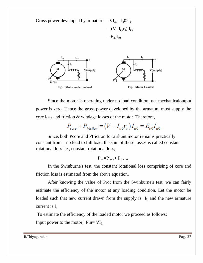
In this test, the motor is run at rated speed under no load condition at rated voltage.
The current drawn from the supply IL0 and the field current If are recorded . Now
we note that:
Input power to the motor, Pin =VIL0
Cu loss in the field circuit Pfl = VIf
Power input to the armature, = fl VIVI 0
= V (IL0– If)
= VIa0
Cu loss in the armature circuit = Ia02ra
R.Thiyagarajan Page 27
Gross power developed by armature = VIa0 - Ia02ra
= (V- Ia0ra) Ia0
= Eb0Ia0
Since the motor is operating under no load condition, net mechanicaloutput
power is zero. Hence the gross power developed by the armature must supply the
core loss and friction & windage losses of the motor. Therefore,
Since, both Pcore and Pfriction for a shunt motor remains practically
constant from no load to full load, the sum of these losses is called constant
rotational loss i.e., constant rotational loss,
Prot=Pcore+ Pfriction
In the Swinburne's test, the constant rotational loss comprising of core and
friction loss is estimated from the above equation.
After knowing the value of Prot from the Swinburne's test, we can fairly
estimate the efficiency of the motor at any loading condition. Let the motor be
loaded such that new current drawn from the supply is IL and the new armature
current is Ia
To estimate the efficiency of the loaded motor we proceed as follows:
Input power to the motor, Pin= VIL
R.Thiyagarajan Page 28
Cu loss in the field circuit Pfl= VIf
Power input to the armature, = VIL- VIf
= V (IL– If)
= VIa
Cu loss in the armature circuit = Ia2ra
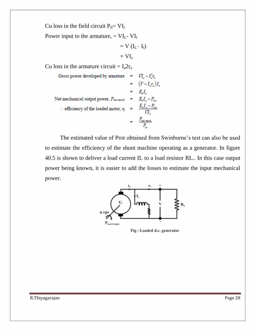
The estimated value of Prot obtained from Swinburne’s test can also be used
to estimate the efficiency of the shunt machine operating as a generator. In figure
40.5 is shown to deliver a load current IL to a load resistor RL.. In this case output
power being known, it is easier to add the losses to estimate the input mechanical
power.

R.Thiyagarajan Page 29
The biggest advantage of Swinburne's test is that the shunt machine is to be
run as motor under no loadcondition requiring little power to be drawn from the
supply; based on the no load reading, efficiency can be predicted for any load
current. However, this test is not sufficient if we want to know more about its
performance (effect of armature reaction, temperature rise, commutation etc.) when
it is actually loaded. Obviously the solution is to load the machine by connecting
mechanical load directly on the shaft for motor or by connecting loading rheostat
across the terminals for generator operation. This although sounds simple but
difficult to implement in the laboratory for high rating machines (say above 20
kW), Thus the laboratory must have proper supply to deliver such a large power
corresponding to the rating of the machine. Secondly, one should have loads to
absorb this power.
6. Explain the characteristics of series, shunt and compound motors.
[NOV/DEC 2010]
D.C. Motor Characteristics
There are three principal types of d.c. motors viz., shunt motors, series
motors and compound motors. Both shunt and series types have only one field
winding wound on the core of each pole of the motor. The compound type has two

R.Thiyagarajan Page 30
separate field windings wound on the core of each pole. The performance of a d.c.
motor can be judged from its characteristic curves known as motor characteristics,
following are the three important characteristics of a d.c. motor:
(i) Torque and Armature current characteristic (Ta/Ia)
It is the curve between armature torque Ta and armature current Ia of a d.c.motor.
It is also known as electrical characteristic of the motor.
(ii) Speed and armature current characteristic (N/ia)
It is the curve between speed N and armature current Ia of a d.c. motor. It is very
important characteristic as it is often the deciding factor in the selection of the
motor for a particular application.
(iii) Speed and torque characteristic (N/Ta)
It is the curve between speed N and armature torque Ta of a d.c. motor. It is
also known as mechanical characteristic.
Characteristics of Shunt Motors
Fig. shows the connections of a d.c. shunt motor. The field current Ish is
constant since the field winding is directly connected to the supply voltage V
which is assumed to be constant. Hence, the flux in a shunt motor is
approximately constant.
(i) Ta/Ia Characteristic. We know that in a d.c. motor,
R.Thiyagarajan Page 31
Ta Ia
Since the motor is operating from a constant supply voltage, flux f is constant
(neglecting armature reaction).
Ta Ia
Hence Ta/Ia characteristic is a straight line passing through the origin as
shown in Fig. The shaft torque (Tsh) is less than Ta and is shown by a dotted
line. It is clear from the curve that a very large current is required to start a
heavy load. Therefore, a shunt motor should not be started on heavy load.
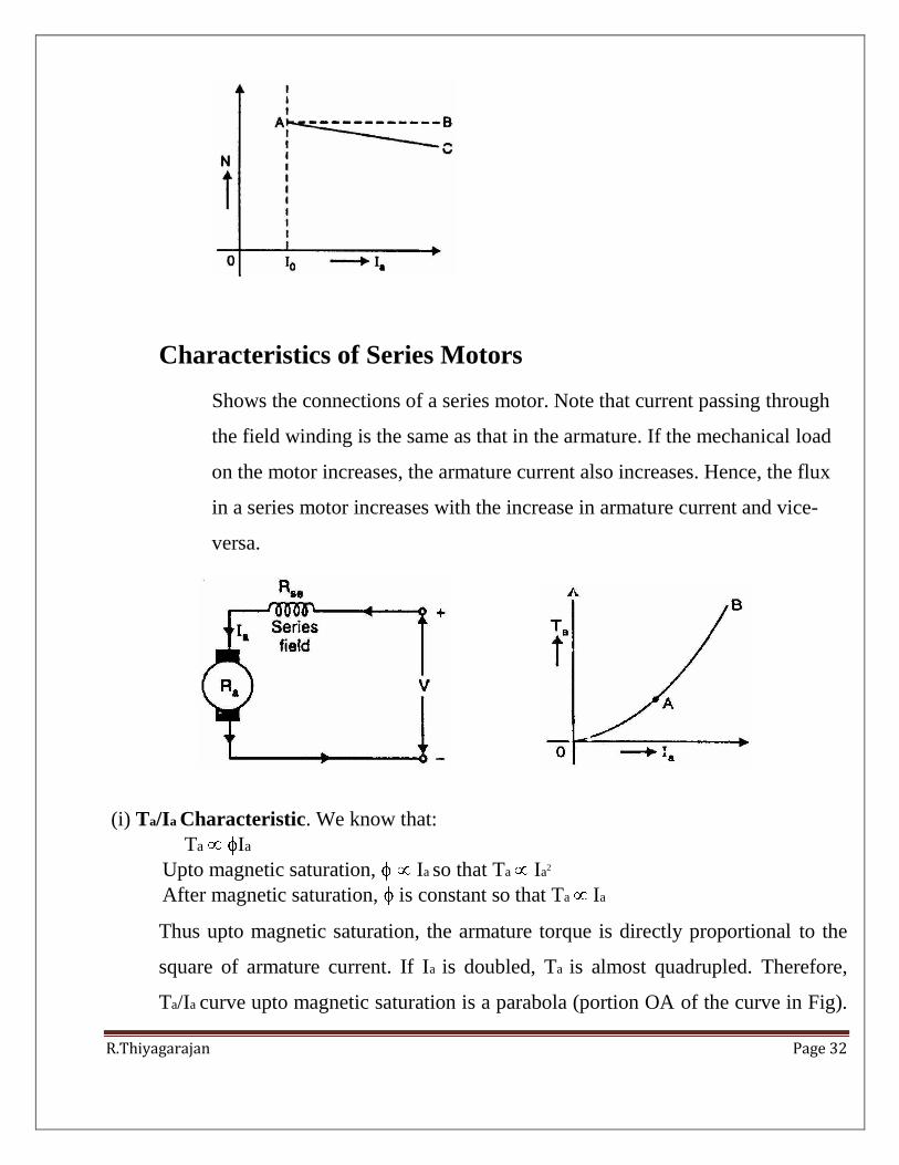
(ii) N/Ia Characteristic. The speed N of a. d.c. motor is given by;
N Eb/
The flux f and back e.m.f. Eb in a shunt motor are almost constant under
normal conditions. Therefore, speed of a shunt motor will remain constant
as the armature current varies (dotted line AB in Fig. 4.15). Strictly
speaking, when load is increased, Eb (= V- IaRa) and f decrease due to the
armature resistance drop and armature reaction respectively. However, Eb
decreases slightly more than f so that the speed of the motor decreases
slightly with load (line AC).
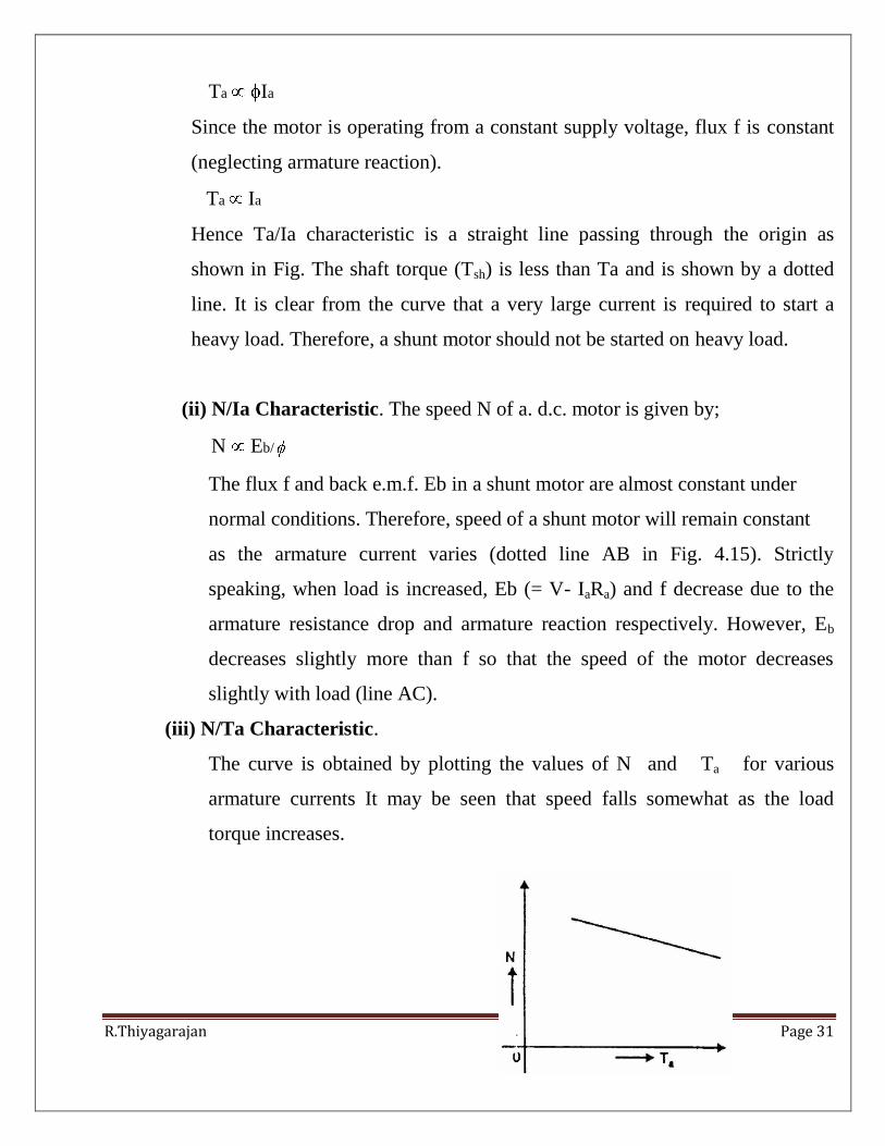
(iii) N/Ta Characteristic.
The curve is obtained by plotting the values of N and Ta for various
armature currents It may be seen that speed falls somewhat as the load
torque increases.
R.Thiyagarajan Page 32
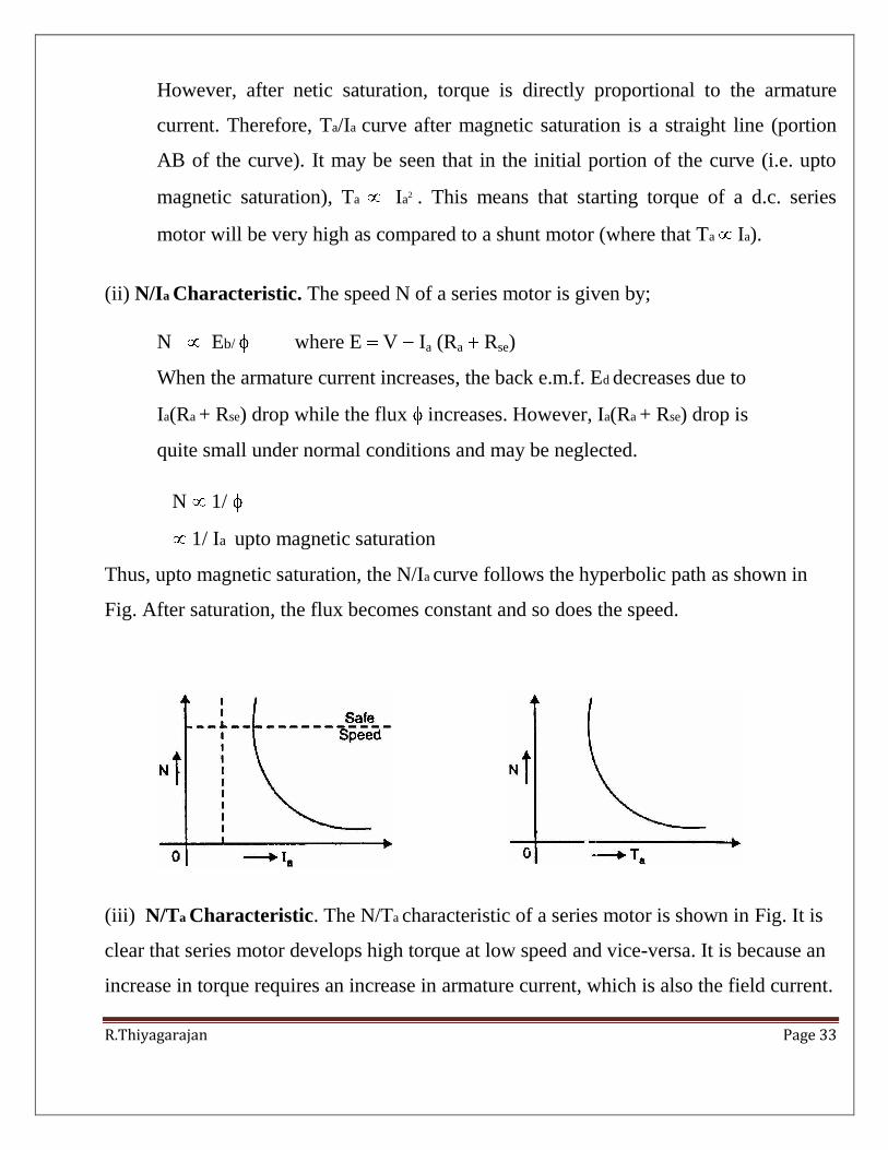
Characteristics of Series Motors
Shows the connections of a series motor. Note that current passing through
the field winding is the same as that in the armature. If the mechanical load
on the motor increases, the armature current also increases. Hence, the flux
in a series motor increases with the increase in armature current and vice-
versa.
(i) Ta/Ia Characteristic. We know that:
Ta Ia
Upto magnetic saturation, Ia so that Ta Ia2
After magnetic saturation, is constant so that Ta Ia
Thus upto magnetic saturation, the armature torque is directly proportional to the
square of armature current. If Ia is doubled, Ta is almost quadrupled. Therefore,
Ta/Ia curve upto magnetic saturation is a parabola (portion OA of the curve in Fig).
R.Thiyagarajan Page 33
However, after netic saturation, torque is directly proportional to the armature
current. Therefore, Ta/Ia curve after magnetic saturation is a straight line (portion
AB of the curve). It may be seen that in the initial portion of the curve (i.e. upto
magnetic saturation), Ta Ia2 . This means that starting torque of a d.c. series
motor will be very high as compared to a shunt motor (where that Ta Ia).
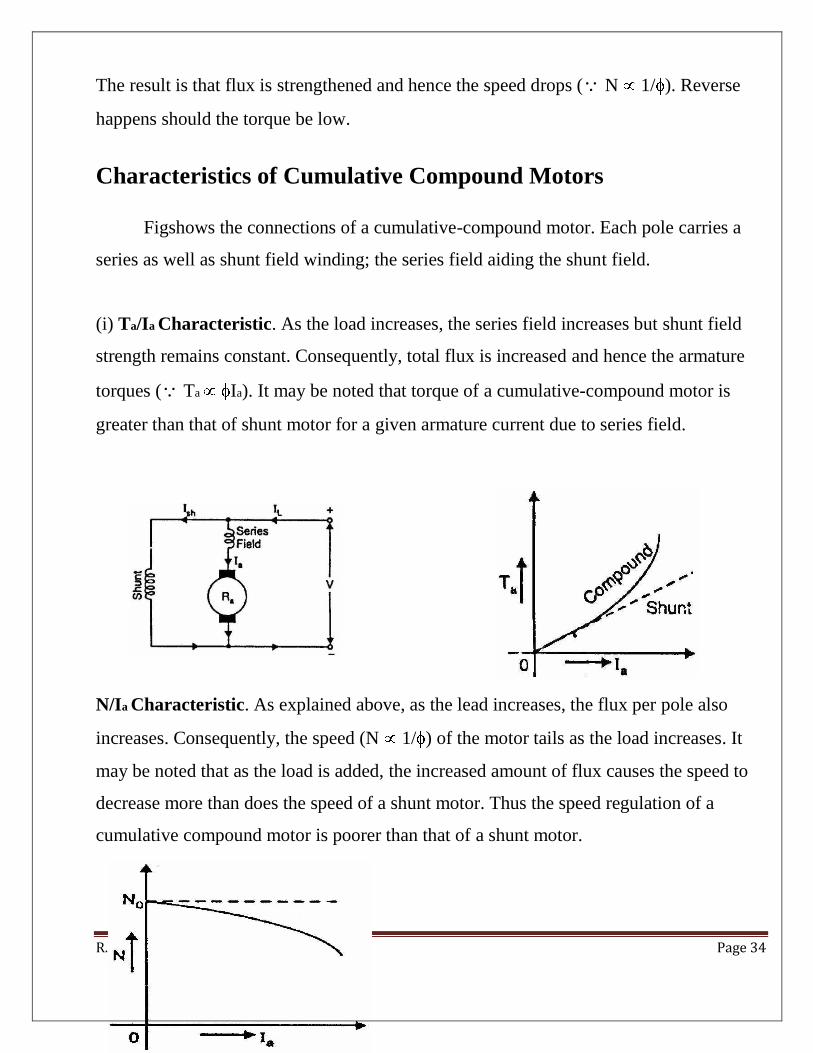
(ii) N/Ia Characteristic. The speed N of a series motor is given by;
N Eb/ where E V Ia (Ra Rse)
When the armature current increases, the back e.m.f. Ed decreases due to
Ia(Ra + Rse) drop while the flux increases. However, Ia(Ra + Rse) drop is
quite small under normal conditions and may be neglected.
N 1/
1/ Ia upto magnetic saturation
Thus, upto magnetic saturation, the N/Ia curve follows the hyperbolic path as shown in
Fig. After saturation, the flux becomes constant and so does the speed.
(iii) N/Ta Characteristic. The N/Ta characteristic of a series motor is shown in Fig. It is
clear that series motor develops high torque at low speed and vice-versa. It is because an
increase in torque requires an increase in armature current, which is also the field current.
R.Thiyagarajan Page 34
The result is that flux is strengthened and hence the speed drops (N 1/ ). Reverse
happens should the torque be low.
Characteristics of Cumulative Compound Motors
Figshows the connections of a cumulative-compound motor. Each pole carries a
series as well as shunt field winding; the series field aiding the shunt field.
(i) Ta/Ia Characteristic. As the load increases, the series field increases but shunt field
strength remains constant. Consequently, total flux is increased and hence the armature
torques (Ta Ia). It may be noted that torque of a cumulative-compound motor is
greater than that of shunt motor for a given armature current due to series field.
N/Ia Characteristic. As explained above, as the lead increases, the flux per pole also
increases. Consequently, the speed (N 1/ ) of the motor tails as the load increases. It
may be noted that as the load is added, the increased amount of flux causes the speed to
decrease more than does the speed of a shunt motor. Thus the speed regulation of a
cumulative compound motor is poorer than that of a shunt motor.
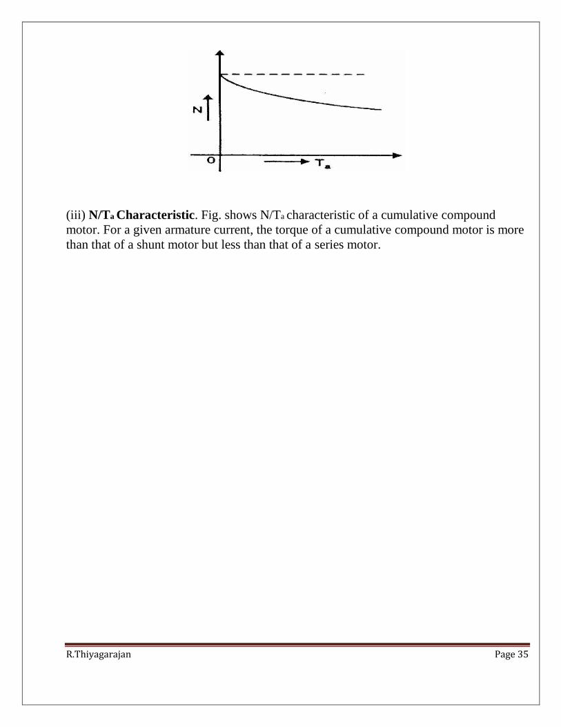
R.Thiyagarajan Page 35
(iii) N/Ta Characteristic. Fig. shows N/Ta characteristic of a cumulative compound
motor. For a given armature current, the torque of a cumulative compound motor is more
than that of a shunt motor but less than that of a series motor.