maharashtra state board of ... - msbte study...
TRANSCRIPT

MAHARASHTRA STATE BOARD OF TECHNICAL EDUCATION (Autonomous)
(ISO/IEC - 27001 - 2005 Certified)
Subject Code : 17528 SUMMER – 15 EXAMINATION Model Answer __________________________________________________________________________________________________
Page 1 of 24
Important Instructions to examiners: 1) The answers should be examined by key words and not as word-to-word as given in the model answer scheme. 2) The model answer and the answer written by candidate may vary but the examiner may try to assess the understanding level of the candidate. 3) The language errors such as grammatical, spelling errors should not be given more Importance (Not applicable for subject English and Communication Skills. 4) While assessing figures, examiner may give credit for principal components indicated in the figure. The figures drawn by candidate and model answer may vary. The examiner may give credit for any equivalent figure drawn. 5) Credits may be given step wise for numerical problems. In some cases, the assumed constant values may vary and there may be some difference in the candidate’s answers and model answer. 6) In case of some questions credit may be given by judgement on part of examiner of relevant answer based on candidate’s understanding. 7) For programming language papers, credit may be given to any other program based on equivalent concept.
Q. No. 01 a) Difference between accuracy and precision ( Any four point 04 marks)
Accuracy Precision
It is the closeness with which an instrument
reading approaches to the true value of the
quantity being measured.
It is the degree of reproducibility among several
independent reading of the same true value
under specified condition.
It is expressed as the limit of error of a
measuring device
It is composed of two characteristics, conformity
and no of significant digits
Accuracy of measurement means conformity of
the truth.
Precision refers to degree of agreement within
group of measurement.
Expressed on the basis of % actual scale or full
scale reading. Accuracy necessarily is with
precision.
Precision in measurement does not guaranties
accuracy
Measurements are dependent on the systematic
errors
Measurements are dependent on the random
errors
Determined by proper calibration Determined by statistical analysis
b) Sensitivity drift and zero drift
Drift is the undesired change in the measured output. It is defined as the variation of output for a given
input caused due to change in the sensitivity of the instrument to certain interfering inputs like temperature
changes, components instabilities, etc. 02 marks
For example, a strain gauge bridge output without a compensating dummy strain gauge may indicate
the output- input characteristics as shown in fig. if the ambient temperature changes after the calibration of the
instrument. An ambient temperature change causes the change in resistance of the strain gauge. This results in

MAHARASHTRA STATE BOARD OF TECHNICAL EDUCATION (Autonomous)
(ISO/IEC - 27001 - 2005 Certified)
Subject Code : 17528 SUMMER – 15 EXAMINATION Model Answer __________________________________________________________________________________________________
Page 2 of 24
the bridge circuit becoming unbalanced and as a consequence of this, there is an output at zero strain which
corresponds to zero drift of the instrument.
02 marks
c) Construction and working of LVDT
LVDT is a displacement measuring device. It is the device which converts the linear displacement in
voltage produced and then the voltmeter is calibrated in terms of displacement. The most widely used
inductive transducer to translate linear motion into electrical signals is the Linear Variable Differential
Transformer (LVDT).
The transformer consists of a single primary winding P1 and two secondary windings S1 and S2, wound on a
cylindrical former. The secondary windings have equal number of turns and are identically placed on either
sides of the primary winding. The primary winding is connected to an alternating current source.
A movable soft iron core is placed inside the former. The displacement to be measured is applied to
an arm attached to the soft iron core. In practice, the core is made of Ni-Fe alloy which is slotted longitudinally
to reduce eddy current losses. When the core is in its normal (null) position, equal voltages are induced in the
two secondary windings. Accordingly, output voltage ES1 of the secondary winding S1 is more than ES2, the
output voltage of secondary winding S2. The magnitude of voltage is thus ES1- ES2 and the output voltage is in
phase with ES1, the output voltage of secondary winding S1. Similarly, if a core is moved to the of null
position, then the flux linking with winding S2 becomes larger than that with winding S1. This results in ES2
becoming larger than Es1. The output voltage in this case is E0 = ES2- ES1 and is in phase with ES2; i.e., the
output voltage of secondary winding S2. 02 marks

MAHARASHTRA STATE BOARD OF TECHNICAL EDUCATION (Autonomous)
(ISO/IEC - 27001 - 2005 Certified)
Subject Code : 17528 SUMMER – 15 EXAMINATION Model Answer __________________________________________________________________________________________________
Page 3 of 24
As the core is moved in one direction from the null position, the differential voltage i.e., the difference
of two secondary voltages, will increase while maintaining an in phase relationship with the voltage from the
input source. In the other direction from the null position, the differential voltage will also increase, but will be
1800 out of phase with the voltage from the source. By comparing the magnitudes and phase of the output
(differential) voltage with that of the source, the amount and direction of the movement of the core and hence,
of displacement, may be determined.
02 marks
d) Mcleod Gauge
02 marks

MAHARASHTRA STATE BOARD OF TECHNICAL EDUCATION (Autonomous)
(ISO/IEC - 27001 - 2005 Certified)
Subject Code : 17528 SUMMER – 15 EXAMINATION Model Answer __________________________________________________________________________________________________
Page 4 of 24
The gas enters the gauge through the open capillary tube and fills the tubes down to the level of
mercury in the reservoir. The pressure is equal through the tubes and the bulb. Mercury is pumped up from the
reservoir. As the mercury raises the cut-off, it traps the gas inside the bulb. The mercury is then pumped higher
in the open end capillary tube until all the gas in the bulb is compressed into the bulb. Operator allows the
mercury to rise until it reaches zero reference line on the closed capillary tube. The mercury rises faster in the
open capillary tube.
The compression of gas in closed capillary tube makes the pressure of trapped gas higher than the
measured pressure. This pressure difference causes difference in the mercury level in the two tubes.
Mathematically pressure is calculated as
P = KHHo(1 - KH) 02 marks
e) Temperature measuring instrument
Non Electrical Methods
• Bimetallic Thermometer in the range 0 to 200 o C
• Liquid in Glass Thermometer the range -120 to 320 o C
• Pressure Thermometer the range 30 to 200 o C
• Vapour Pressure Thermometer the range 30 to 200 o C
Electrical Methods 02 marks
• Resistance Temperature Detector ( RTD ) range -200 to 600 o C
• Thermistors range -100 to 500 o C
• Thermocouples -30 to 1200 o C
Non Contact type temperature measurement
• Radiation Pyrometer range 600 to 2000 o C
• Optical Pyrometer 600 to 2000 o C 02 marks
f) Flow measuring device (each 01 marks)
Rotameter : Measure Liquid or Gas Flows in refrigeration system
Hot wire anemometer: widely used in research application to study varying flow conditions.
Electromagnetic Flow meter: Obstruction less flow meter used in chemical process plant
Ultrasonic flow meter: Obstruction less flow meter used where high flow rate is to be measured R & D work
g) Requirements of strain gauge material (for two points 01 marks)
i. Strain gauge should be small in size with negligible mass.
ii. It should be highly sensitive to strain.
iii. Strain gauge should have high value of gauge factor.
iv. It should be easily attachable to specimen.

MAHARASHTRA STATE BOARD OF TECHNICAL EDUCATION (Autonomous)
(ISO/IEC - 27001 - 2005 Certified)
Subject Code : 17528 SUMMER – 15 EXAMINATION Model Answer __________________________________________________________________________________________________
Page 5 of 24
v. It should have high speed of response with negligible time lag.
vi. It should be capable to indicate static, transient and dynamic strain.
vii. It should be capable of remote indication and recording.
viii. It should not be sensitive to ambient condition such as temperature, humidity, vibration etc.
ix. It should be inexpensive, reliable and easily available in various sizes
Q. No: 02 a) Dynamic properties of Measuring instrument (Any two properties 2 marks each)
These are measuring lag, fidelity, speed of response and overshoot
OVERSHOOT:
The overshoot is defined as the maximum amount by which the pointer moves beyond the
steady state. Because of mass and inertia, a moving parts, i.e. the pointer of the instrument does not
immediately comes to rest in the final deflection position. The pointer goes beyond the steady state i.e.
it overshoots.
FIDELITY:
It is the degree of closeness with which the system indicates the signal which is imposed upon
it. It refers to the ability of the system to reproduce the output in the same form in the input. If the
input is a sine wave then for 100% fidelity the output should also be a sine wave.
b) Comparison of Hydraulic and pneumatic system (min four points 01 mark each)
Hydraulic controller
Pneumatic controller
Medium cost
Low cost
Chances of fire hazard
No fire hazard
high speed of response
Medium speed of response
High power gain Medium power gain

MAHARASHTRA STATE BOARD OF TECHNICAL EDUCATION (Autonomous)
(ISO/IEC - 27001 - 2005 Certified)
Subject Code : 17528 SUMMER – 15 EXAMINATION Model Answer __________________________________________________________________________________________________
Page 6 of 24
Medium space require
High space require
Not affected by stray magnetic field
Not affected by stray magnetic field
High power gain
Medium power gain
c) PID control action
Proportional control action is good when
Very fast and settling time is less. If error is zero output is constant Used for steady condition
Not satisfactory when
If load changes are rapid that exists long period
Process rate reaction is very fast
There is considerable dead time 02 marks
A proportional controller (Kp) will have the effect of reducing the rise time and will reduce, but never
eliminate, the steady-state error.
An integral control (Ki) will have the effect of eliminating the steady-state error, but it may make the transient
response worse.
A derivative control (Kd) will have the effect of increasing the stability of the system, reducing the overshoot,
and improving the transient response.
Proportional Control
By only employing proportional control, a steady state error occurs.
Proportional and Integral Control
The response becomes more oscillatory and needs longer to settle, the error disappears.
Proportional, Integral and Derivative Control
All design specifications can be reached. 02 marks
d) Potentiometers are used for measuring linear and angular displacement
Rotational type Potentiometer
The rotational resistive elements are circular in shape and used for measurement of angular
displacement.

MAHARASHTRA STATE BOARD OF TECHNICAL EDUCATION (Autonomous)
(ISO/IEC - 27001 - 2005 Certified)
Subject Code : 17528 SUMMER – 15 EXAMINATION Model Answer __________________________________________________________________________________________________
Page 7 of 24
02 marks
linear type Potentiometer
The translatory resistive elements are straight or liner devices used for measurement of liner displacement
Working Principle
Positioning of the slider by a external force varies the resistance in potentiometer or a bridge circuit.
Consider a traslatory or liner potentiometer as shown in previous figure.
Let ei and eo = Input and Output voltages,
Xt = Total length of liner pot in meter
Xi= Displacement of wiper from its zero position in meter
Rp= total resistance of potentiometer.
The movement is linear, so resistance per unit length is Rp / Xi
Hence, output voltage is ,
MAHARASHTRA STATE BOARD OF TECHNICAL EDUCATION (Autonomous)
(ISO/IEC - 27001 - 2005 Certified)
Subject Code : 17528 SUMMER – 15 EXAMINATION Model Answer __________________________________________________________________________________________________
Page 8 of 24
Under ideal circumstances, the output voltage varies linearly with displacement as shown in figure.
02 marks
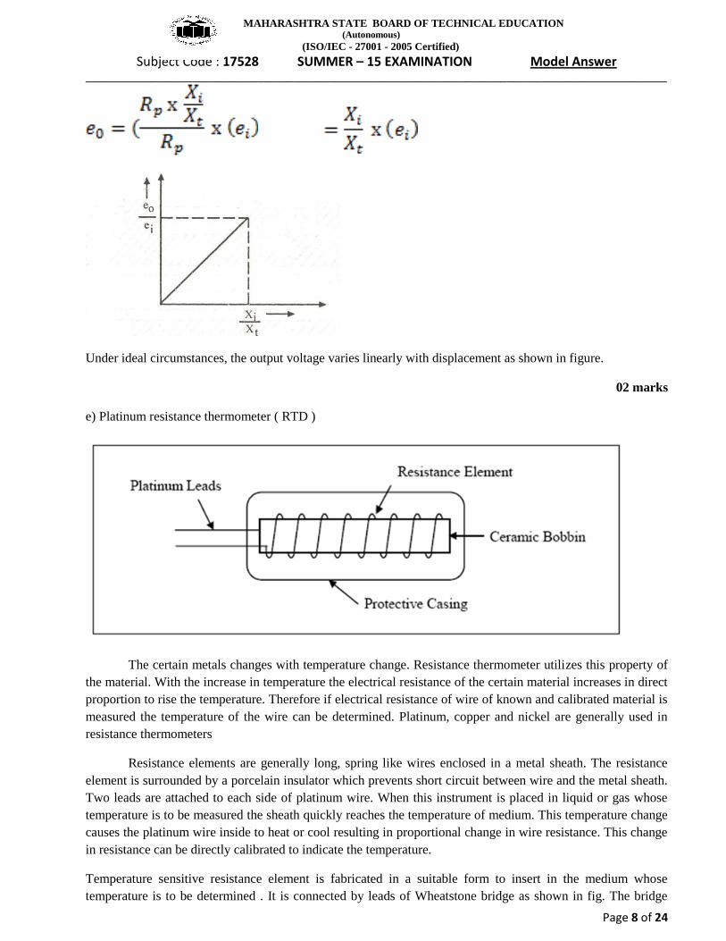
e) Platinum resistance thermometer ( RTD )
The certain metals changes with temperature change. Resistance thermometer utilizes this property of
the material. With the increase in temperature the electrical resistance of the certain material increases in direct
proportion to rise the temperature. Therefore if electrical resistance of wire of known and calibrated material is
measured the temperature of the wire can be determined. Platinum, copper and nickel are generally used in
resistance thermometers
Resistance elements are generally long, spring like wires enclosed in a metal sheath. The resistance
element is surrounded by a porcelain insulator which prevents short circuit between wire and the metal sheath.
Two leads are attached to each side of platinum wire. When this instrument is placed in liquid or gas whose
temperature is to be measured the sheath quickly reaches the temperature of medium. This temperature change
causes the platinum wire inside to heat or cool resulting in proportional change in wire resistance. This change
in resistance can be directly calibrated to indicate the temperature.
Temperature sensitive resistance element is fabricated in a suitable form to insert in the medium whose
temperature is to be determined . It is connected by leads of Wheatstone bridge as shown in fig. The bridge

MAHARASHTRA STATE BOARD OF TECHNICAL EDUCATION (Autonomous)
(ISO/IEC - 27001 - 2005 Certified)
Subject Code : 17528 SUMMER – 15 EXAMINATION Model Answer __________________________________________________________________________________________________
Page 9 of 24
consists of sensing element resistance X having high temperature coefficient and resistances A, B, and C
whose resistances do not alter with change of temperature.
02 marks
In the balanced condition
A/B = (X + LR1 + LR2)/C
Rt = Ro ( 1 + α t )
When resistance X changes the Wheatstone bridge becomes unbalanced and thus galvanometer will give
deflection which can be calibrated to give a suitable temperature scale.
RTD Material
Platinum RTD 100 ohm wire
Temperature Range
-240 to 650 oC
02 marks
f) Turbine flow meter
Turbine flow meter is suitable for measurement of flow in tubes and pipes. The rotor is placed in path
of moving stream directly. The rotor spins freely at the rate proportional to flow velocity. The permanent
magnet is sealed inside the rotor body is polarized at 90 degree to the axis of rotation. As rotor rotates, along
with it magnet also rotates and produces rotating magnetic field. This produces an AC voltage pulse in the pick
up coil located external to the meter housing. The frequency of this voltage is directly proportional to the rate
of flow. Alternatively, the frequency is converted into voltage and is fed to an analog /digital voltmeter to give
the rate of flow. In turbine flow meter it is possible to get measurement of total flow as well as rate of flow.
02+02 marks

MAHARASHTRA STATE BOARD OF TECHNICAL EDUCATION (Autonomous)
(ISO/IEC - 27001 - 2005 Certified)
Subject Code : 17528 SUMMER – 15 EXAMINATION Model Answer __________________________________________________________________________________________________
Page 10 of 24
Advantages of Turbine flow meter : ( ADVANTAGES/DISADVANTAGES is OPTIONAL)
Very good accuracy ±1 % over design range.
It has low pressure drop.
Analog as well as digital readings can be obtained.
It gives fast response.
Disadvantages of turbine flow meter :
Bearing maintenance is the problem.
Accuracy drops at low flow rates.
It is costly.
It has very limited application.
It requires line mounting.
Qu.3. Attempt Any FOUR of the following 4X4 Marks
a) Explain with neat sketch working of any one thermo resistive transducer.
( Fig. with labelling 2 marks & working 2 marks.)

MAHARASHTRA STATE BOARD OF TECHNICAL EDUCATION (Autonomous)
(ISO/IEC - 27001 - 2005 Certified)
Subject Code : 17528 SUMMER – 15 EXAMINATION Model Answer __________________________________________________________________________________________________
Page 11 of 24
Resistance thermometers or resistance temperature detector works on the principle of positive
temperature coefficient of resistance i.e as temperature increases, resistance offered by thermometer
also increases.
The resistance element of platinum and iron metal wire is wrapped around an electrically insulating
support of glass, ceramic or mica and from the outside, protective sheath of metallic tube can be
provided. The lead wires are taken out from the resistance elements which are joined to the circuitry.
The resistance thermometers which are alternatively known as RTD works on the principal that “ the
resistance of a metal varies with a change in temperature” according to the relation as
RT =R0[1+α(T-T0)
RT : Resistance at temperature ( T)
R0 : Resistance at temperature ( 0˚C)
α : Temp. coeff.
T: temp( ˚C)
T0 : Initial temp.
To measure the change in resistance bridge network is used.
The resitsance thermometer is connected to one of the arm of Wheatstone bridge circuit when
resistance thermometer is subjected to temperature variation, the Wheatstone bridge gets
unbalanced.\the galvanometer deflection can be directly calibrated to give temperature.
b) What is psychometer ? Draw a neat sketch of sling psychrometer with proper labelling.
(Definition: 01 mark, Fig. 2 marks & labelling 1 mark)
Psychometer: The equipment used for measuring “ Dry Bulb Temperature” and “Wet Bulb
Temperature” Simultaneously is known as psychrometer.
The sling psychrometer consists of two mercury thermometers mounted on frame, which has handle
provided for rotation of psychrometer. Thus air movement is obtained by whirling the thermometer in
air. One bulb among the two is covered with the wet wick to read wet bulb temperature. The velocity
recommended for rotation is 5 to 8m/min.

MAHARASHTRA STATE BOARD OF TECHNICAL EDUCATION (Autonomous)
(ISO/IEC - 27001 - 2005 Certified)
Subject Code : 17528 SUMMER – 15 EXAMINATION Model Answer __________________________________________________________________________________________________
Page 12 of 24
Sling psychrometer
.
c) Explain with a neat sketch the float and tape gauge liquid level measurement method.
(Explanation 2 marks and figure 2 marks)
In this, a freely floating body ( float) is used for continuous liquid level measurement .the float is
attached to the cable /tape which passes over the pulley and then at another end of tape, the weight is
applied for counter –balancing of force.
At the center of another pulley, a pointer is attached which transverses along the calibrated scale to
give the direct reading of liquid level.
The float used may be hollow metal spheres (disc) shaped synthetic materials.
d) Explain the positive and negative feedback in a closed loop control system with suitable
example of each.

MAHARASHTRA STATE BOARD OF TECHNICAL EDUCATION (Autonomous)
(ISO/IEC - 27001 - 2005 Certified)
Subject Code : 17528 SUMMER – 15 EXAMINATION Model Answer __________________________________________________________________________________________________
Page 13 of 24
Ans: ( Positive feedback 2 marks, negative feedback 2 marks )
Positive feedback :
Whereas positive feedback tends to lead to instability via exponential growth or oscillation, negative
feedback generally promotes stability. Negative feedback tends to promote a settling to equilibrium,
and reduces the effects of perturbations. Negative feedback loops in which just the right amount of
correction is applied in the most timely manner can be very stable, accurate, and responsive.
In a “positive feedback control system”, the set point and output values are added together by the
controller as the feedback is “in-phase” with the input. The effect of positive (or regenerative)
feedback is to “increase” the systems gain, ie, the overall gain with positive feedback applied will be
greater than the gain without feedback.
However, in electronic and control systems to much praise and positive feedback can increase the
systems gain far too much which would give rise to oscillatory circuit responses as it increases the
magnitude of the effective input signal.
e.g: Refrigerator, air conditioner etc.
Negative feedback
Negative feedback occurs when some function of the output of a system, process, or mechanism
is fed back in a manner that tends to reduce the fluctuations in the output, whether caused by changes
in the input or by other disturbances. Negative feedback is widely used in mechanical and electronic
engineering, but it also occurs naturally within living organisms,[1][2]
and can be seen in many other
fields from chemistry and economics to physical systems such as the climate. General negative
feedback systems are studied in control systems engineering.
E.g :D.C MOTOR speed controller
e) Explain with a neat sketch the construction and working of thermocouple .what are the
different materials used for developing thermocouple.
( Figure : 1 mark, construction : 1 mark, working 1 mark, material : 1 mark )
Construction:

MAHARASHTRA STATE BOARD OF TECHNICAL EDUCATION (Autonomous)
(ISO/IEC - 27001 - 2005 Certified)
Subject Code : 17528 SUMMER – 15 EXAMINATION Model Answer __________________________________________________________________________________________________
Page 14 of 24
When two dissimilar metals m1 & m2 are joined together to form a loop, it is called as thermocouple
and if two unequal temperature T1& T2 ae imposed at two junctions J1 & J2,then an electric current
flows through the loop and this is called as “Seeback Effect”
Working: When a junction (J1) is kept at a hot body and another junction (J2)is kept at some constant
known temperature ,then the EMF generated is proportional to the temperature difference imposed
and this forms the basis of temperature measurement.
Different material used In thermocouple:
Copper: Constantan
Iron: Constantan
Chromel: Alumel
Chromel : Constantan
Platinum: (90% platinum + 10 % Rhodium) (95% Tungsten +5% Rhenium) –( 80% Tungsten +20%
Rhenium) etc.
f) Explain the working of Rotameter with neat sketch
(Explanation 2 marks and figure 2 marks)
The rotameter consists of three basic elements:
1) A uniformly tapered flow tube, 2) a float, and 3) a measurement scale.
A control valve may be added if flow control is also desired. In operation, the rotameter is positioned
vertically in the fluid system with the smallest diameter end of the tapered flow tube at the bottom.
This is the fluid inlet. The float, typically spherical, is located inside the flow tube, and is engineered
so that its diameter is nearly identical to the flow tube’s inlet diameter.
When fluid like gas or liquid is introduced into the tube, the float is lifted from its initial position at
the inlet, allowing the fluid to pass between it and the tube wall. As the float rises, more and more
fluid flows by the float because the tapered tube’s diameter is increasing. Ultimately, a point is
reached where the drag force exerted by the fluid is balance by weight of float and gravitational force.
The float is now stationary at that level within the tube as its weight is being supported by the fluid

MAHARASHTRA STATE BOARD OF TECHNICAL EDUCATION (Autonomous)
(ISO/IEC - 27001 - 2005 Certified)
Subject Code : 17528 SUMMER – 15 EXAMINATION Model Answer __________________________________________________________________________________________________
Page 15 of 24
forces which caused it to rise. This position corresponds to a point on the tube’s measurement scale
and provides an indication of the fluid’s flow rate.
QU.4 Attempt any four of the following
a)List advantages and disadvantages of capacitive transducer used for measurement of
displacement
Ans: ( Advantages 2 pt: 2 marks, Disadvantages: 2 marks)
Advantages
It produces an accurate frequency response to both static and dynamic measurements.
Working principle is very simple
They are inexpensive
Disadvantages
An increase or decrease in temperature to a high level will change the accuracy of the device.
As the lead is lengthy it can cause errors or distortion in signals
b)Compare pressure gauge measurement devices ,diaphragm, and bellows on the basis 1)
Working principal 2) construction 3) Pressure range 4) applications
Sr.
No
Paramete
r
Diaphragm Bellow
1 Working
Principal
The deflection of diaphragm is
proportional to applied pressure.
A Bellow guage contains an elastic
element that is a convoluted unit that
expands and contracts axially with
changes in pressure. The pressure to be
measured can be applied to the outside
or inside of the bellows.
2 Construct
ion
A thin member of sheet metal
made to precision dimensions
either in shape of memebrane or
circular disc.
bellows gauges are made of brass,
phosphorbronze, stainless steel,
beryllium-copper, or other metalthat
is suitable for the intended purpose of
the gauge
3 Pressure
Range
0 to 6.7 KPa Pressures up to 800 psig, their primary
application aboard ship is in the
measurement of low pressures or small

MAHARASHTRA STATE BOARD OF TECHNICAL EDUCATION (Autonomous)
(ISO/IEC - 27001 - 2005 Certified)
Subject Code : 17528 SUMMER – 15 EXAMINATION Model Answer __________________________________________________________________________________________________
Page 16 of 24
pressure differentials.
4 Applicati
on
Ind. process pressure
measurement,
Manifold pressure measurement
Abroad Ship, also some type of
recording device
Each difference Point : 1mark
c) Explain working of turbine meter for flow measurement with neat sketch.
(Figure with labelling: 2 marks , Working 2 marks)
The turbine flow meter works on the principle of turbine. if the losses are kept minimum the turbine
speed varies linearly with flow rate i.e flow rate can be measured by measuring the speed of the
turbine. When the blade passes by pick up coil, it interrupt magnetic field and produces a pulse. The
rate of pulse gives flow rate and total number of pulses gives a measure of the total flow.
d) What are thermistors? Explain the principal of operation and give its advantages
Thermistor: It is thermally sensitive variable resistor. These are a temperature measurement device
that has a negative temperature coefficient. Def: 1mark
Principle of Operation: principle: 2 marks

MAHARASHTRA STATE BOARD OF TECHNICAL EDUCATION (Autonomous)
(ISO/IEC - 27001 - 2005 Certified)
Subject Code : 17528 SUMMER – 15 EXAMINATION Model Answer __________________________________________________________________________________________________
Page 17 of 24
These are made up of ceramic like semi conducting materials like copper oxide ,manganese oxide
,nickel oxide, cobalt oxide, Lithium oxide and titanium oxide.
These oxides are blended in a suitable proportional and compressed into the desired shapes from the
mixed power and heat treated to recrystallize them, resulting in the dense ceramic body with the
required resistance temperature characteristics.
For the thermistor, as the temperature increases ,its resistance decreases and vice versa and this is
called as negative temperature characteristics” of thermocouple.
The thermistor is a very non linear instrument,wheras resistors such as platimum ,copper,tungstaen
are quite linear.the resistance temperature relation for thermistor is as under
.
]
Where,
R-Resistance at any temperature (T) in ˚K
R0 –Resistance at the refernace “ Temperature( T0) in ˚K
Β = Constant = 3000 K to 4500 K, depending on its composition.
The practical operating range of thermistors lies between -100 to +300 ˚C.
Advantages: Advantages: 1 mark
1) Simple in construction & working
2) More durable
e) Explain with the neat sketch strain gauge transmission dynamometer
(Fig. 2m & Explanation 2m)

MAHARASHTRA STATE BOARD OF TECHNICAL EDUCATION (Autonomous)
(ISO/IEC - 27001 - 2005 Certified)
Subject Code : 17528 SUMMER – 15 EXAMINATION Model Answer __________________________________________________________________________________________________
Page 18 of 24
The principle involved in transmission dynamometer is that the power being transmitted either to or
from the dynamometer is not absorbed or dissipated. The power after measurement is available in
useful mechanical or electrical means. However, a small power is dissipated on account of friction.
Strain gauge transmission dynamometer is used to measure bending strains rather than strains due to
torque at 450 and so an arrangement using beams (as shown in fig.) may be employed, in which the
transmitted torque results in bending the beams.
The strain gauge transmission dynamometer utilizes the bonded strain gauges which are applied to a
section of torque transmission shaft.
This is inline rotating torque sensor which measures torque.
This dynamometer is used as a coupling between driving machine and driven machine or between
any two portions of the machine. Here strain gauges are fitted at 45˚ to shaft axis as shown in fig.
In this type of arrangement, 2 strain gauges are subjected to tensile stress and while other is subjected
to compressive stress.
Strain gauge 1 & 3 must be diametrically opposite to strain gauge 2 & 4.Due to torsion, strain gauge
senses compressive as well as tensile formation. Further these strain gauges are connected to
Wheatstone circuit. the output of Wheatstone bridge is proportional to torsion and hence to applied
torque on shaft. The bridge power and output of bridge is connected to the sensor through slip ring
and brushes .
Advantages: 1) It is sensitive to torque.
2) it gives an instantaneous results.
3) it has full temperature compensation
4) it provides automatic compensation for bending and axial loads
Disadvantages:
The device is expensive
Initial setting need skill and is time consuming.

MAHARASHTRA STATE BOARD OF TECHNICAL EDUCATION (Autonomous)
(ISO/IEC - 27001 - 2005 Certified)
Subject Code : 17528 SUMMER – 15 EXAMINATION Model Answer __________________________________________________________________________________________________
Page 19 of 24
f) Draw the block diagram of feed forward control system and state its advantages
(Figure : 2 Marks , Advantages 4 pts: 2 Marks )
Advantages:
1) In this system, corrective action is taken for a change in a input before it affects the control
parameter.
2) It prevents accidents before they occur.
3) It useful for processes with large time constants or/and long time delays.
3) It is easy to be accepted and implemented
Q.No.5 Attempt any FOUR……………………… 04 Marks × 04 = 16 Marks
a) Difference between systematic and random errors…………..( 1 mark each)
Sr. Random Errors Systematic Errors
1 Accidental, small and independent Repeated consistantly with the repetition
of experiment
2 Caused due to inconstant factors such as
spring hysteresis, stickiness, friction , noise
and threshold limitations.
Caused due to sensitivity effects , zero
offset and known non linearity.
3 Magnitude and direction cannot be
predicted from knowledge of measurement
system.
Way to locate these errors is to have
repeated measurements under different
conditions or with different equpment and
if possible by different method.
4 Errors are assumed to follow the law of
probabilities.
Cannot be determined by the direct and
repetitive observations of the measurand
made each time with the same technique.

MAHARASHTRA STATE BOARD OF TECHNICAL EDUCATION (Autonomous)
(ISO/IEC - 27001 - 2005 Certified)
Subject Code : 17528 SUMMER – 15 EXAMINATION Model Answer __________________________________________________________________________________________________
Page 20 of 24
b) Advantages of Pirani gauge…………………………...…(1/2 mark each of following) - More accurate than thermocouple gauges. - Wide pressure reading range ( 10-5 to 1 Torr) - Fast response to pressure changes. - Possibility of process control and remote reading. Disadvantages of Pirani gauge - Expensive than thermocouple gauges. - Lineariry dependent on the part of the range used. - Need for individual and frequent calibration for different gases. - Requires electrical power. c) Optical Pyrometer
...Labelled diagram. 1 mark … .......Filament diagram 1 mark Principle: Monocromatic radiation wavelength of a fixed color from a hot surface of body whose temperature is to be measured, is compared with a standard filament light wavelength. Working: The current through the lamp filament is made variable so that lamp intensity can be adjusted. The filament is viewed the eyepiece and filter. The current through the filament is so adjusted that filament and image are of euqal brightness. When brightness of source and image produced is same , we can say that both temperatures are same. If the temperature of filament is higher than that required for equal brightness, filament become too bright as shown in figure. (High). And if the temperature of filament is lower , it becomes too dark as shown in figure (Low). Range- 14000C, can be incresed upto 30000C…………….(Correct Explanation-2 marks) d) Eddy Current dynamometer.
...Labelled diagram. 2 marks

MAHARASHTRA STATE BOARD OF TECHNICAL EDUCATION (Autonomous)
(ISO/IEC - 27001 - 2005 Certified)
Subject Code : 17528 SUMMER – 15 EXAMINATION Model Answer __________________________________________________________________________________________________
Page 21 of 24
Principle: When an isolated conductor moves through the magnetic flux, voltage is induced and local currents flow in a short circular path (eddy currents) within conductor. These induced eddy currents get dissipated in the form of heat. Working: It consists of toothed nonmagnetic solid metallic rotor connected to the shaft whose power is to be measured. Nonmagnetic rotor rotates inside cast iron stator. Stator consists of D.C. supply excited coil. The stator is mounted such that it permits free swing about its axis and is provided with torque arm, which measures torque. To dissipate the generated heat, water is supplied in stator casing. During operation, rotor turns and causes constant change in flux density at all points of stator, resulting formation of eddy current, which opposes the motion of rotor. This opposing resistance is measured by brake drum in the form of torque. Apprx. Speed limit = 6000 rpm. Usual power limit = 250 kW……………… …………….(Correct Explanation-2 marks)
e) Air Conditioner:
...Labelled diagram. 2 mark Components – Controller, Compressor, Evaporator (Room temp), Temperature sensor,
(Condensor not shown in fig. outside temp source.) -Air conditioner works on the feedback control system. -The componenets are shown in the figure. -Air conditioner maintains the room temperature and humidity at some preset values. - -Temperature sensor continuosly monitors the room temperature and signals the controller. -When the room temperature is more than the set value it switch ON the compressor which hwlps to absorb the excessive heat inside the room. On reaching the preset value of temperature and humidity it switch OFF the compressor. Note: If the student is drawing and writing about humidification and dehumidification using humidifier and heater, shall also be given due credit…………….... Correct Explanation-2 marks
f) ON-OFF control system. ...Labelled diagram. 1 mark .....Triangular form diagram 1 mark

MAHARASHTRA STATE BOARD OF TECHNICAL EDUCATION (Autonomous)
(ISO/IEC - 27001 - 2005 Certified)
Subject Code : 17528 SUMMER – 15 EXAMINATION Model Answer __________________________________________________________________________________________________
Page 22 of 24
- Simplest type of controller and also called as two position controller. - ON-OFF controller keep measured variable within certain tolerance band of desired value or
the set point. - Figure shows time- temperature response of ON-OFF controller in heating application. - Ideally ON –OFF controller, should be ON when measured variable is below set point and
should be OFF when measured variable is above the set point. - Actually the process lag or the dead time delays the switching ON and OFF at the exact set
point values. - This gap where controller output does not change although it is supposed to, is called the
‘differential gap’ or ‘dead zone’ - Suitable for room heaters, refrigerators and liquid level control applications.
……………………… (Correct Explanation-2 marks) Q.No.6 Attempt any FOUR……………………………………04 Marks × 04= 16 Marks
(a) Difference between active and passive transducer. ( Any four points- 1 mark each)
Active Transducer Passive Transducer
Operates under energy conversion
principle
Operates under energy controlling
principle.
Develop their own voltage or current. Derive the required power for energy
conversion from an external power source.
Energy required is absorbed from the
physical quantity being measured.
May absorb a little energy from the process
variabel being measured.
Generate equivalent output signal without
energizing source.
Measurand is converted into passive
parameter such as resistance, inductance,
capacitance which needs external energy
source so as to get equivalent electrical
signal.
e.g.Thermocouples and thermopiles,
piezoelectric pickup, photovoltaic cell
e.g. resistance thermometers and
thermistors, potentiometric devices, photo
emmissive cell
(b) Incremental encoders:
……...Labelled diagram. 2 marks

MAHARASHTRA STATE BOARD OF TECHNICAL EDUCATION (Autonomous)
(ISO/IEC - 27001 - 2005 Certified)
Subject Code : 17528 SUMMER – 15 EXAMINATION Model Answer __________________________________________________________________________________________________
Page 23 of 24
-Also referred to as a quadrature encoder. -Utilizes sensors that use optical, mechanical or magnetic index counting for angular measurement. -Utilize a transparent disk which contains opaque sections that are equally spaced to determine movement.
-A light emitting diode is used to pass light through the glass disk and is detected by a photo detector. -Encoder generates a train of equally spaced pulses as it rotates. -The output of incremental rotary encoders is measured in pulses per revolution which is used to keep track of position or determine speed.
………………………(Correct Explanation-2 marks) (c) Comparison between thermocouple and thermistor. (Any four correct differences- 4 marks)
Thermocouple Thermistor
Construction Rugged,simple Complex
Temperature Range -2700C to 27000C -1000C to 3000C
Size Comparatively large Very small
Sensitivity Poor Excellent
Cost Cheaper Expensive
Effect of ambient condition Accuracy gets affected Accuracy is unaffected
(d) Electromagnetic flow meter.
...Labelled diagram. 2 mark Limitations:
Relatively high cost.
Suitable for the fluids having conductivity at least of the order of 0.05 μ mho/cm.
Not suitable for low velocities ………………….(Any two correct limitations- 2 marks)

MAHARASHTRA STATE BOARD OF TECHNICAL EDUCATION (Autonomous)
(ISO/IEC - 27001 - 2005 Certified)
Subject Code : 17528 SUMMER – 15 EXAMINATION Model Answer __________________________________________________________________________________________________
Page 24 of 24
(e) Semiconductor Strain gauge.
...Labelled diagram. 2 mark These gauges are produced from silicon and germanium crystals in which a certain amount of special impurities are added to impart certain characteristics. Two types a) Negative or n-type, whose resistance decreases in response to tensile strain b) Positive or p-type, whose resistance increases in response to tensile strain. Breaking stress of material rises as the cross sectional area decreases. The gauge is in the form of single rectangular filament about 0.05 mm thick and 0.25 mm wide and 1.5 mm to 12 mm in length. ………...………………………(Correct Explanation-1 mark) Advantages:
Very high sensitivity in comparison of metal gauges.
High gauge factor in range of 100 to 200.
Low hysteresis………………………...…………..(Any two correct advantages- 1 mark) (f) Domestic air conditioner using feedback control system.
...Labelled diagram. 2 mark
-Figure shows air conditioner which works on the feedback control system. -The componenets are shown in the figure. -Air conditioner maintains the room temperature and humidity at some preset values. - -Temperature sensor (feedback element) continuosly monitors the room temperature and signals the controller. -When the room temperature is more than the set value it switch ON the compressor which hwlps to absorb the excessive heat inside the room. On reaching the preset value of temperature and humidity it switch OFF the compressor……….(Correct Explanation-2 marks)