main block series - microsoft block and connector coupling color cap fitting tube valve controller...
TRANSCRIPT

310
http://www.pisco.co.jp
Block andConnector
Coupling
ColorCap
FITTING
TUBE
VALVE
CONTROLLERMAKE-TO-ORDERPRODUCTS
Concentrated Branching Joint for AssemblyMain Block Series
●Assembling Manifold Blocks for Concentrated Branching
●Combination with 14 Types of Different Size Blocks
●Same Flow Rate with Steel Piping. Half Size Body.
Fitting SeriesMain Block
Block andConnector
311
Twist-ProofFitting
RotarySeries
Stop FittingSeries
MinimalSeries
Die TemperatureControl
Anti-spatter& Brass Series
EGSeries
PPSeries
ChemicalSeries
StainlessSeries
MiniSeries
StandardSeries
FITT
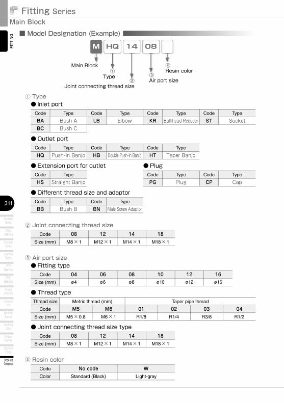
ING ■ Model Designation (Example)
HQM 14 08
② Joint connecting thread size
③ Air port size
Thread size Metric thread (mm) Taper pipe thread
Code M5 M6 01 02 03 04Size (mm) M5×0.8 M6×1 R1/8 R1/4 R3/8 R1/2
① Type
Code 08 12 14 18Size (mm) M8×1 M12×1 M14×1 M18×1
Main Block①
Type ③Air port size②
Joint connecting thread size
● Inlet portCode Type Code Type Code Type Code Type
BA Bush A LB Elbow KR Bulkhead Reducer ST SocketBC Bush C
● Outlet portCode Type Code Type Code Type
HQ Push-in Banjo HB Double Push-in Banjo HT Taper Banjo
● Extension port for outletCode Type
HS Straight Banjo
● PlugCode Type Code Type
PG Plug CP Cap
● Different thread size and adaptorCode Type Code Type
BB Bush B BN Male Screw Adaptor
● Fitting typeCode 04 06 08 10 12 16
Size (mm) ø4 ø6 ø8 ø10 ø12 ø16
● Thread type
● Joint connecting thread size typeCode 08 12 14 18
Size (mm) M8×1 M12×1 M14×1 M18×1
④Resin color
④ Resin colorCode No code WColor Standard (Black) Light-gray
312
http://www.pisco.co.jp
Block andConnector
Coupling
ColorCap
FITTING
TUB
EVA
LVECONTROLLER
MAKE-TO-ORDERPRODUCTS
■ Specifi cationsFluid medium Air
Max. operating pressure 1.0MPa
Max. vacuum -100kPa
Operating temp. range 0~60℃ (No freezing)
■ Construction (MHQ)
Air
Elastic sleeve (NBR)
Female thread
Tube
Release ring (POM)
Lock-claws (Stainless steel)
O-ring (NBR)
Tube end
Fitting Body (PBT)
Metallic Body (Nickel-plated brass)
Guide ring (Nickel-plated brass)
Male thread
■ Model Designation of Coupling Module (Example)
QMC20
Coupling module
※ Joint connecting thread size of coupling module is M18x1 only
※ Use Light Coupling 20 series for the coupling module plug. See page 342.
● Coupling module of outlet port
①Body color
① Body colorCode No code WColor Standard (Black) Light-gray
Fitting SeriesMain Block
Block andConnector
313
Twist-ProofFitting
RotarySeries
Stop FittingSeries
MinimalSeries
Die TemperatureControl
Anti-spatter& Brass Series
EGSeries
PPSeries
ChemicalSeries
StainlessSeries
MiniSeries
StandardSeries
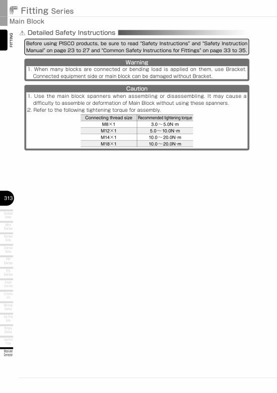
FITTING Detailed Safety Instructions
Before using PISCO products, be sure to read “Safety Instructions” and “Safety Instruction Manual” on page 23 to 27 and “Common Safety Instructions for Fittings” on page 33 to 35.
Warning1. When many blocks are connected or bending load is applied on them, use Bracket.
Connected equipment side or main block can be damaged without Bracket.
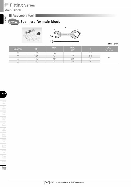
Caution1. Use the main block spanners when assembling or disassembling. It may cause a
difficulty to assemble or deformation of Main Block without using these spanners.2. Refer to the following tightening torque for assembly.
Connecting thread size Recommended tightening torqueM8×1 3.0~5.0N・mM12×1 5.0~10.0N・mM14×1 10.0~20.0N・mM18×1 10.0~20.0N・m
314
http://www.pisco.co.jp
Block andConnector
Coupling
ColorCap
FITTING
TUBE
VALVE
CONTROLLERMAKE-TO-ORDERPRODUCTS
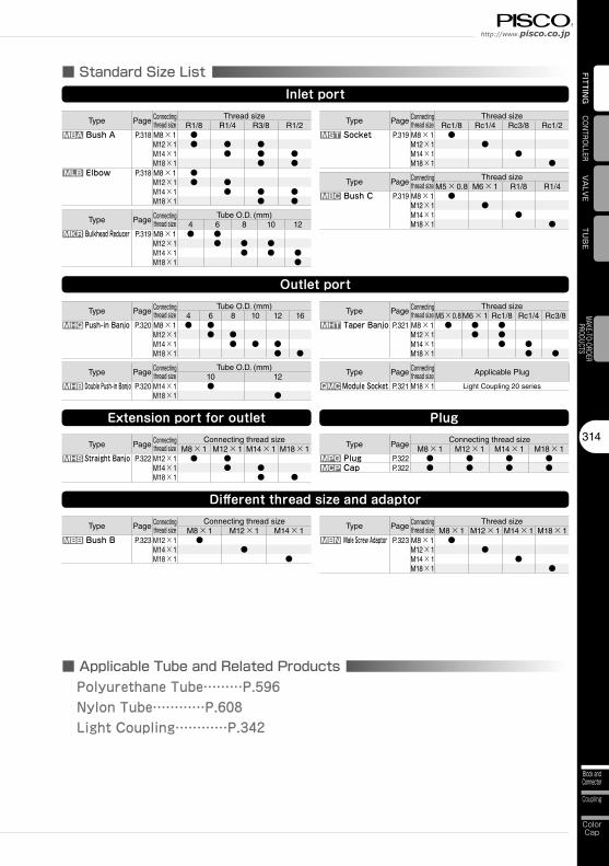
Type Page Connecting thread size
Thread sizeR1/8 R1/4 R3/8 R1/2
MBA Bush A P.318 M8×1 ●M12×1 ● ● ●M14×1 ● ● ●M18×1 ● ●
MLB Elbow P.318 M8×1 ●M12×1 ● ●M14×1 ● ● ●M18×1 ● ●
■ Standard Size ListInlet port
Type Page Connecting thread size
Tube O.D. (mm)4 6 8 10 12
MKR Bulkhead Reducer P.319 M8×1 ● ●M12×1 ● ● ●M14×1 ● ● ●M18×1 ●
Type Page Connecting thread size
Thread sizeRc1/8 Rc1/4 Rc3/8 Rc1/2
MST Socket P.319 M8×1 ●M12×1 ●M14×1 ●M18×1 ●
Type Page Connecting thread size
Thread sizeM5×0.8 M6×1 R1/8 R1/4
MBC Bush C P.319 M8×1 ●M12×1 ●M14×1 ●M18×1 ●
Type Page Connecting thread size
Tube O.D. (mm)4 6 8 10 12 16
MHQ Push-in Banjo P.320 M8×1 ● ●M12×1 ● ●M14×1 ● ● ●M18×1 ● ●
Outlet port
Type Page Connecting thread size
Tube O.D. (mm)10 12
MHB Double Push-in Banjo P.320 M14×1 ●M18×1 ●
Type Page Connecting thread size
Thread sizeM5×0.8 M6×1 Rc1/8 Rc1/4 Rc3/8
MHT Taper Banjo P.321 M8×1 ● ● ●M12×1 ● ●M14×1 ● ●M18×1 ● ●
Type Page Connecting thread size
Connecting thread sizeM8×1 M12×1 M14×1 M18×1
MHS Straight Banjo P.322 M12×1 ● ●M14×1 ● ●M18×1 ● ●
Extension port for outlet
Type PageConnecting thread size
M8×1 M12×1 M14×1 M18×1MPG Plug P.322 ● ● ● ●MCP Cap P.322 ● ● ● ●
Plug
Type Page Connecting thread size
Connecting thread sizeM8×1 M12×1 M14×1
MBB Bush B P.323 M12×1 ●M14×1 ●M18×1 ●
Different thread size and adaptor
Type Page Connecting thread size
Thread sizeM8×1 M12×1 M14×1 M18×1
MBN Male Screw Adaptor P.323 M8×1 ●M12×1 ●M14×1 ●M18×1 ●
Type Page Connecting thread size Applicable Plug
QMC Module Socket P.321 M18×1 Light Coupling 20 series
■ Applicable Tube and Related ProductsPolyurethane Tube………P.596Nylon Tube…………P.608Light Coupling…………P.342
Fitting SeriesMain Block
Block andConnector
315
Twist-ProofFitting
RotarySeries
Stop FittingSeries
MinimalSeries
Die TemperatureControl
Anti-spatter& Brass Series
EGSeries
PPSeries
ChemicalSeries
StainlessSeries
MiniSeries
StandardSeries
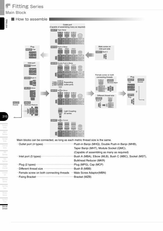
FITTING ■ How to assemble
Main blocks can be connected, as long as each metric thread size is the same.
・Outlet port (4 types) …………………………… Push-in Banjo (MHQ), Double Push-in Banjo (MHB),
Taper Banjo (MHT), Module Socket (QMC)、 (Capable of assembling as many as required)
・Inlet port (5 types) ……………………………… Bush A (MBA), Elbow (MLB), Bush C (MBC), Socket (MST),
Bulkhead Reducer (MKR)
・Plug (2 types) ……………………………………Plug (MPG), Cap (MCP)
・Different thread size ……………………………Bush B (MBB)
・Female screw on both connecting threads …Male Screw Adaptor(MBN)
・Fixing Bracket……………………………………Bracket (MZB)
MCP
MHT
MBC
MCP
MPG
MBN
MBB
MHQ
MHB
MHS
MST
MBA
MLB
MKRMZB
MZB
Taper Banjo
Push-in Banjo
Double Push-in Banjo
Expandingoutlet ports
Light Coupling20 series
Inlet port
Different thread size
Female screw on both connecting threads
Male screw on inlet port side
Outlet port(Capable of assembling many as required)
Cap
Socket
Bush A
Elbow
Bulkhead Reducer
Cap
Plug
Bracket Male Screw Adaptor
Bush B
Bush C
Bracket
Straight Banjo Straight Banjo
QMC Module Socket Module Socket
Plug
Plug
MKR
316
http://www.pisco.co.jp
Block andConnector
Coupling
ColorCap
FITTING
TUBE
VALVE
CONTROLLERMAKE-TO-ORDERPRODUCTS
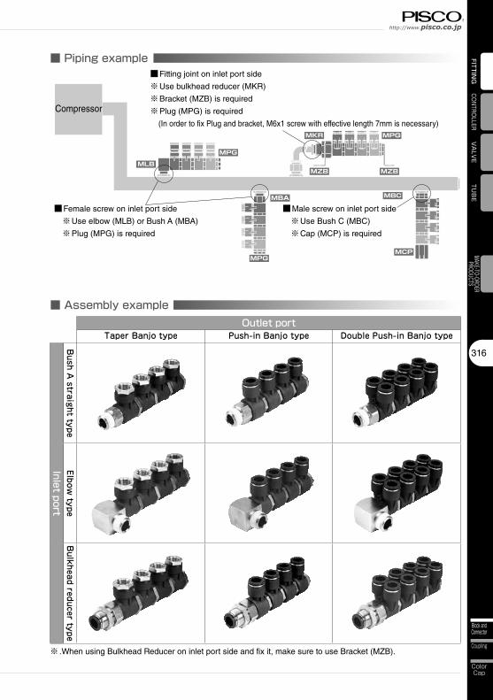
■ Assembly exampleOutlet port
Taper Banjo type Push-in Banjo type Double Push-in Banjo type
Inlet portB
ush A straight type
Elbow type
Bulkhead reducer type
※ . When using Bulkhead Reducer on inlet port side and fix it, make sure to use Bracket (MZB).
■ Piping example
Compressor
MPG
MPG
MPG
MKR
MLB
MBA MBC
MCP
MZB MZB
■Fitting joint on inlet port side
※Use bulkhead reducer (MKR)
※Bracket (MZB) is required
※Plug (MPG) is required
(In order to fix Plug and bracket, M6x1 screw with effective length 7mm is necessary)
■ Female screw on inlet port side
※Use elbow (MLB) or Bush A (MBA)
※Plug (MPG) is required
■ Male screw on inlet port side
※Use Bush C (MBC)
※Cap (MCP) is required

Fitting SeriesMain Block
Block andConnector
317
Twist-ProofFitting
RotarySeries
Stop FittingSeries
MinimalSeries
Die TemperatureControl
Anti-spatter& Brass Series
EGSeries
PPSeries
ChemicalSeries
StainlessSeries
MiniSeries
StandardSeries
FITTING ■ How to insert and disconnect
1. How to insert and disconnect tubes① Tube insertion
Insert a tube into Push-In Fitting up to the tube end. Lock-claws bite the tube
and fix it automatically, then the elastic sleeve seals around the tube.
Refer to “2. Instructions for Tube Insertion” under “Common Safety Instructions
for Fittings” .
② Tube disconnection
The tube is disconnected by pushing release-ring to release Lock-claws.
Make sure to stop air supply before the tube disconnection.
2. How to tighten thread① Tightening thread
Use a spanner to tighten a hexagonal-column.
Refer to “Table 2: Recommended tightening torque / Sealock color / Gasket
materials” under “4. Instructions for Installing a fitting” in “Common Safety
Instructions for Fittings”.
Hexagonal-column
3. How to couple and uncouple coupling module① Coupling
To couple, push the plug into the socket. No need to push down plug sleeve.
Refer to “Detailed Safety Instructions” of Light Coupling.
② . Uncoupling
To uncouple, push down the release sleeve to release Lock ball.
Refer to “Detailed Safety Instructions” of Light Coupling.
Release sleeve(1)
(2)
318
http://www.pisco.co.jp
Block andConnector
Coupling
ColorCap
FITTING
TUB
EVA
LVECONTROLLER
MAKE-TO-ORDERPRODUCTS
CAD data is available at PISCO website.CAD
MBA
Unit:mm
Model code R M A1 A2 B L HEffective area
(mm2)Weight
(g)CAD
file name
MBA0801 R1/8 M8×1 8 8 20 16 12 24.5 11
TFMB-001
MBA1201 R1/8M12×1
88.5
20 1617
24.7 18
MBA1202 R1/4 11 23 1742.3
20
MBA1203 R3/8 12 24 17.7 27
MBA1402 R1/4M14×1
11 8.5 23 1719 42.7
23
MBA1403 R3/8 128
24 17.7 25
MBA1404 R1/2 13 25 16.8 22 56.1 46
MBA1803 R3/8M18×1
128.5 25
18.7 2256.1
29
MBA1804 R1/2 13 16.8 24 45
※ . “L” is a reference value for height dimension after tightening thread.
A1
A2
B
L
R
H M
CADBush A
■ Inlet port
MLB
Unit:mm
Model code R M A1 A2 B L1 L2 □EEffective area(mm2)
Weight(g)
CADfile name
MLB0801 R1/8 M8×1 8 7 28 16 24 17 21.4 42
TFMB-002
MLB1201 R1/8M12×1
88.5
29 15 2519
24.5 48
MLB1202 R1/4 11 32 16 26 40 50
MLB1402 R1/4M14×1
118.5
37 19 3122
42.7 80
MLB1403 R3/8 12 38 19.7 31.746
82
MLB1404 R1/2 13 39 18.8 30.8 93
MLB1803 R3/8M18×1
129
44 23.7 37.727 49
141
MLB1804 R1/2 13 45 22.8 36.8 157
※ . “L1” and “L2” are reference values for height dimensions after tightening thread.
L1L2
B
A1
R
□E
M
A2
Elbow
compliant
compliant
CAD

Fitting SeriesMain Block
Block andConnector
319
Twist-ProofFitting
RotarySeries
Stop FittingSeries
MinimalSeries
Die TemperatureControl
Anti-spatter& Brass Series
EGSeries
PPSeries
ChemicalSeries
StainlessSeries
MiniSeries
StandardSeries
FITT
ING
CAD data is available at PISCO website.CAD
MKR
Unit:mm
Model codeTube O.D.
øD M1 M2 A B E1 E2Tube end
CG H1 H2
Effective area(mm2)
Weight(g)
CADfile name
MKR0804□ 4M8×1
M12×18.5
268
13.4 14.94
14 14 5.6 19
TFMB-003
MKR0806□ 6 M14×1 28.1 14.9 17 17 17 11.5 29
MKR1206□ 6M12×1
M14×18.5
28.1 12 10.9 174
17 17 13.2 28
MKR1208□ 8 M16×1 28.910
13.4 18.2 19 19 27.4 34
MKR1210□ 10 M20×1 32.3 16.4 20.7 5 22 24 34.8 60
MKR1408□ 8M14×1
M16×18.5
28.9 12 11.4 18.2 4 19 19 27.7 33
MKR1410□ 10 M20×1 32.3 10 16.4 20.7 524
24 41.7 64
MKR1412□ 12 M22×1 34.9 12 17.4 23.3 6 27 54.7 78
MKR1812□ 12 M18×1 M22×1 8.5 34.9 12 17.4 23.3 6 27 27 66.7 83
※ . □ in Model code / Replaced with “W” for Light-gray color.
GA
C
B E2
E1
M1
øD
H1
H2 M2Bulkhead Reducer
MST
Unit:mm
Model code Rc M A1 A2 B HWeight
(g)CAD
file name
MST0801 Rc1/8 M8×1 8 9 20 12 12
TFMB-004MST1202 Rc1/4 M12×1 11 9 24 17 29
MST1403 Rc3/8 M14×1 12 10 27 22 57
MST1804 Rc1/2 M18×1 15 10 28 27 84
BA
2A
1
Rc
HMSocket
MBC
Unit:mm
Model code Rc M A1 A2 B HWeight
(g)CAD
file name
MBC08M5 M5×0.8 M8×1 7 5 11 10 3.8
TFMB-009MBC12M6 M6×1 M12×1 7.5 6 11.5 14 9.6
MBC1401 Rc1/8 M14×1 8 8 12 17 12
MBC1802 Rc1/4 M18×1 8 11 13 19 17
B
A1A
2
M
HRc
O-ring
Bush C
compliant
compliant
compliant
CAD
CAD
CAD
320
http://www.pisco.co.jp
Block andConnector
Coupling
ColorCap
FITTING
TUB
EVA
LVECONTROLLER
MAKE-TO-ORDERPRODUCTS
CAD data is available at PISCO website.CAD
MHQ
Unit:mm
Model codeTube O.D.
øD M A1 A2 B L1 L2 øP1 øP2 Tube endC
E HEffective area(mm2)
Weight(g)
CADfile name
MHQ0804□ 4M8×1 6.5 7.5 25.7 8.2 19.2
1015.4
14.9 22.214
4.7 16
TFMB-005
MHQ0806□ 6 12.5 17 24.2 7 17
MHQ1206□ 6M12×1 7 7.5 27.2 8.7 20.2
12.519.6
17 26.817
8.7 23
MHQ1208□ 8 14.5 18.1 28.2 11 25
MHQ1408□ 8M14×1 8 8.5 31.2
10.223.2
14.524.4
18.1 30.222
16.7 39
MHQ1410□ 10 18 20.2 32.5 19.5 42
MHQ1412□ 12 11.7 21 23.4 35.2 21.1 45
MHQ1812□ 12M18×1 8
8.5 35.2 11.7 27.2 21 30 23.4 38.2 24 40.4 61
MHQ1816□ 16 8 41.1 14.6 33.1 25 28 23.6 36.6 27 50.4 71
※ . □ in Model code / Replaced with “W” for Light-gray color.
L1A
2
øP
1ø
D
(A1)
L2B
2-M
HE
C
øP2 O-ring
Push-in Banjo
■ Outlet port
MHB
Unit:mm
Model codeTube O.D.
øD M B L1 L2 øP1 øP2 Tube endC
E J F HEffective area(mm2)
Weight(g)
CADfile name
MHB1410□ 10 M14×1 31.2 10.2 23.2 17.6 23 20.7 33.5 17 15 22 17.8 49TFMB-007
MHB1812□ 12 M18×1 35.2 11.7 27.2 21 27 23.4 37.4 20 17 24 35.6 70
※ . □ in Model code / Replaced with “W” for Light-gray color.
L2B(8
)
2-ø
Dø
P1
J
L1(8.
5)
2-M
H E
2-C
F
øP2 O-ring
ø4.2
Double Push-in Banjo
compliant
compliant
CAD
CAD

Fitting SeriesMain Block
Block andConnector
321
Twist-ProofFitting
RotarySeries
Stop FittingSeries
MinimalSeries
Die TemperatureControl
Anti-spatter& Brass Series
EGSeries
PPSeries
ChemicalSeries
StainlessSeries
MiniSeries
StandardSeries
FITT
ING
CAD data is available at PISCO website.CAD
MHT
Unit:mm
Model code Rc M A1 A2 A3 B L1 L2 øP1 øP2 E H1 H2Effective area(mm2)
Weight(g)
CADfile name
MHT08M5□ M5×0.8M8×1 6.5 7.5
625.7 8.2 19.2
12.515.4
23.414
12 7.3 22
TFMB-006
MHT08M6□ M6×1MHT0801□ Rc1/8 8 14.5 25.5 14 7.8 23
MHT12M6□ M6×1M12×1 7 7.5
627.2 8.7 20.2
12.519.6
2617
12 9.7 28
MHT1201□ Rc1/8 8 14.5 27.5 14 12.4 29
MHT1401□ Rc1/8M14×1 8 8.5
831.2
10.223.2
14.524.4
29.522
14 16.1 44
MHT1402□ Rc1/4 11 11.7 21 34 19 21.4 59
MHT1802□ Rc1/4M18×1 8
8.5 11 35.2 11.7 27.2 21 30 37 24 19 36.9 75
MHT1803□ Rc3/8 8 12 41.1 14.6 33.1 25 28 36.5 27 22 59.5 91
※ . □ in Model code / Replaced with “W” for Light-gray color.
L1A
2
øP
1
(A1)
L2B
H2
2-M
H1A3
E
øP2
Rc
O-ring
Taper Banjo
compliant
CAD
QMC
Model codeWeight
(g)CAD
file name
QMC20□ 84 TFLC-004
※ . □ in Model code / Replaced with “W” for Light-gray color.
41
8
18.58
M18×1
O-ring Hex.27
ø25
56.3
ø28
Module Socket
compliant
CAD
■ Outlet port
※ . Select the plug for the Coupling Module from Light Coupling 20 series. See page 342.

322
http://www.pisco.co.jp
Block andConnector
Coupling
ColorCap
FITTING
TUB
EVA
LVECONTROLLER
MAKE-TO-ORDERPRODUCTS
CAD data is available at PISCO website.CAD
MPG
Unit:mm
Model code M A1 A2 B HWeight
(g)CAD
file name
MPG08 M8×1 6 5 14 12 9
TFMB-008MPG12 M12×1 6 5 9 14 7.9
MPG14 M14×1 6 5 10 17 14
MPG18 M18×1 7 6 12 19 25
B
A1
A2
M
HM6×1
O-ring
Plug
■ Plug
compliant
CAD
MHS
Unit:mm
Model code M1 M2 A1 A2 A3 B L1 L2 øP1 øP2 E H1 H2Effective area(mm2)
Weight(g)
CADfile name
MHS1208□M12×1
M8×17 7.5
727.2
8.720.2
12.519.6
2617
12 8.4 26
TFMB-007
MHS1212□ M12×1 7.5 10.2 18 29.5 17 12.9 35
MHS1412□M14×1
M12×18 8.5
7.531.2
10.223.2
1824.4
31.522
17 20.8 49
MHS1414□ M14×1 8.5 11.7 21 34 19 20.6 55
MHS1814□M18×1
M14×18
8.58.5
35.2 11.7 27.2 21 30 37 24 19 40.1 71
MHS1818□ M18×1 8 41.1 14.6 33.1 25 28 35.5 27 22 59.9 86
※ .□ in Model code / Replaced with “W” for Light-gray color.
L1A
2A
1
øP
1
L2B
H2
2-M1
H1A3
E
øP2
M2
O-ring
Straight Banjo
■ Expanding outlet port
compliant
CAD
MCP
Unit:mm
Model code M A B HWeight
(g)CAD
file name
MCP08 M8×1 6.5 20 12 17
TFMB-008MCP12 M12×1 7 22 14 22
MCP14 M14×1 8 23 17 34
MCP18 M18×1 8 25 22 64
B
A5
HM
M6×1
Cap
compliant
CAD

Fitting SeriesMain Block
Block andConnector
323
Twist-ProofFitting
RotarySeries
Stop FittingSeries
MinimalSeries
Die TemperatureControl
Anti-spatter& Brass Series
EGSeries
PPSeries
ChemicalSeries
StainlessSeries
MiniSeries
StandardSeries
FITT
ING
CAD data is available at PISCO website.CAD
MBB
Unit:mm
Model code M1 M2 A B HWeight
(g)CAD
file name
MBB1208 M12×1 M8×1 8 12 14 7.4TFMB-009MBB1412 M14×1 M12×1 7.5 20 17 21
MBB1814 M18×1 M14×1 12 12 19 11
B8
A
M1O-ring
H M2
Bush B
■ Adapter
MBN
Unit:mm
Model code M A B HWeight
(g)CAD
file name
MBN0808 M8×1 7 18 10 5.6
TFMB-009MBN1212 M12×1 8 20 14 13
MBN1414 M14×1 8 20 17 16
MBN1818 M18×1 8 20 19 19
B
2-A
2-M
O-ring
H
Male Screw Adaptor
compliant
compliant
CAD
CAD

324
http://www.pisco.co.jp
Block andConnector
Coupling
ColorCap
FITTING
TUB
EVA
LVECONTROLLER
MAKE-TO-ORDERPRODUCTS
CAD data is available at PISCO website.CAD
MZB
Unit:mm
Model code B1 B2 J1 E J2 YWeight
(g)Attachable
ModelCAD
file name
MZB061B75
6562.5
32.5 46 12 73MPG、MCP
TFMB-011MZB062B 80 40 63 13 84
MZB161B55
6542.5
32.5 46 12 64MPG、MCP
MZB162B 80 40 63 13 73
J2B2
E
7
20
Y
27J1
B1
3 37
10
15
Bracket
■ Bracket
MZB
Unit:mm
Model code ød Weight(g)
Attachable ModelCAD
file name
MZB06 7 28 MPG、MCP
TFMB-010
MZB12 13 26 MKR0804
MZB14 15 26 MKR0806、MKR1206MZB16 17 25 MKR1208、MKR1408MZB20 21 23 MKR1210、MKR1410、MKR1810MZB22 23 22 MKR1412、MKR1812
2
2513
2
25
41
32
ød
2-ø6.5
20
Bracket
compliant
compliant
CAD
CAD
Fitting SeriesMain Block
Block andConnector
325
Twist-ProofFitting
RotarySeries
Stop FittingSeries
MinimalSeries
Die TemperatureControl
Anti-spatter& Brass Series
EGSeries
PPSeries
ChemicalSeries
StainlessSeries
MiniSeries
StandardSeries
FITT
ING
CAD data is available at PISCO website.CAD
SPANNER
Unit:mm
Spanner BHex.H1
Hex.H2
T CADfile name
① 125 10 12 3.4
-② 130 14 17 3.4③ 140 19 22 4④ 150 24 27 4
B
H2
H1
T
Spanners for main block
■ Assembly tool
23
Safety Instructions
SAFETY Instructions
Warning
This safety instructions aim to prevent personal injury and damage to properties by requiring proper use of PISCO products. Be certain to follow ISO 4414 and JIS B 8370
ISO 4414:Pneumatic fluid power…Recomendations for the application of equipment to transmission and control systems.
JIS B 8370:General rules and safety requirements for systems and their components.This safety instructions is classified into “Danger”, “Warning” and “Caution” depending on the degree of danger or damages caused by improper use of PISCO products.
1. Selection of pneumatic products① A user who is a pneumatic system designer or has sufficient experience
and technical expertise should select PISCO products.② Due to wide variety of operating conditions and applications for PISCO
products, carry out the analysis and evaluation on PISCO products. The pneumatic system designer is solely responsible for assuring that the user's requirements are met and that the application presents no health or safety hazards. All designers are required to fully understand the specifications of PISCO products and constitute all systems based on the latest catalog or information, considering any malfunctions.
2. Handle the pneumatic equipment with enough knowledge and experience① Improper use of compressed air is dangerous. Assembly, operation
and maintenance of machines using pneumatic equipment should be conducted by a person with enough knowledge and experience.
3. Do not operate machine / equipment or remove pneumatic equipment until safety is confirmed.① Make sure that preventive measures against falling work-pieces or
sudden movements of machine are completed before inspection or maintenance of these machine.
② Make sure the above preventive measures are completed. A compressed air supply and the power supply to the machine must be off, and also the compressed air in the systems must be exhausted.
③ Restart the machines with care after ensuring to take all preventive measures against sudden movements.
Danger Hazardous conditions. It can cause death or serious personal injury.
Warning Hazardous conditions depending on usages. Improper use of PISCO products can cause death or serious personal injury.
Caution Hazardous conditions depending on usages. Improper use of PISCO products can cause personal injury or damages to properties.
※ . This safety instructions are subject to change without notice.
http://www.pisco.co.jphttp://www.pisco.co.jp
24
Disclaimer1. PISCO does not take any responsibility for any incidental or indirect
loss, such as production line stop, interruption of business, loss of benefits, personal injury, etc., caused by any failure on use or application of PISCO products.
2. PISCO does not take any responsibility for any loss caused by natural disasters, fires not related to PISCO products, acts by third parties, and intentional or accidental damages of PISCO products due to incorrect usage.
3. PISCO does not take any responsibility for any loss caused by improper usage of PISCO products such as exceeding the specification limit or not following the usage the published instructions and catalog allow.
4. PISCO does not take any responsibility for any loss caused by remodeling of PISCO products, or by combinational use with non-PISCO products and other software systems.
5. The damages caused by the defect of Pisco products shall be covered but limited to the full amount of the PISCO products paid by the customer.
25
Safety Instructions
SAFETY INSTRUCTION MANUAL
Danger1. Do not use PISCO products for the following applications.
① Equipment used for maintaining / handling human life and body.② Equipment used for moving / transporting human.③ Equipment specifically used for safety purposes.
Warning1. Do not use PISCO products under the following conditions.
① Beyond the specifications or conditions stated in the catalog, or the instructions.② Under the direct sunlight or outdoors.③ Excessive vibrations and impacts.④ Exposure / adhere to corrosive gas, inflammable gas, chemicals, seawater, water and vapor. *
* Some products can be used under the condition above(④), refer to the details of specification and condition of each product.
2. Do not disassemble or modify PISCO products, which affect the performance, function, and basic structure of the product.
3. Turn off the power supply, stop the air supply to PISCO products, and make sure there is no residual air pressure in the pipes before maintenance and inspection.
4. Do not touch the release-ring of push-in fitting when there is a working pressure. The lock may be released by the physical contact, and tube may fly out or slip out.
5. Frequent switchover of compressed air may generate heat, and there is a risk of causing burn injury.
6. Avoid any load on PISCO products, such as a tensile strength, twisting and bending. Otherwise, there is a risk of causing damage to the products.
7. As for applications where threads or tubes swing / rotate, use Rotary Joints, High Rotary Joints or Multi-Circuit Rotary Block only. The other PISCO products can be damaged in these applications.
8. Use only Die Temperature Control Fitting Series, Tube Fitting Stainless SUS316 Series, Tube Fitting Stainless SUS316 Compression Fitting Series or Tube Fitting Brass Series under the condition of over 60℃ (140°F) water or thermal oil. Other PISCO products can be damaged by heat and hydrolysis under the condition above.
9. As for the condition required to dissipate static electricity or provide an antistatic performance, use EG series fitting and antistatic products only, and do not use other PISCO products. There is a risk that static electricity can cause system defects or failures.
10. Use only Fittings with a characteristic of spatter-proof such as Anti-spatter or Brass series in a place where flame and weld spatter is produced. There is a risk of causing fire by sparks.
11. Turn off the power supply to PISCO products, and make sure there is no residual air pressure in the pipes and equipment before maintenance. Follow the instructions below in order to ensure safety.① Make sure the safety of all systems related to PISCO products before maintenance.② Restart of operation after maintenance shall be proceeded with care after
ensuring safety of the system by preventive measures against unexpected movements of machines and devices where pneumatic equipment is used.
③ Keep enough space for maintenance when designing a circuit.12. Take safety measures such as providing a protection cover if there is a
risk of causing damages or fires on machine / facilities by a fluid leakage.
PISCO products are designed and manufactured for use in general industrial machines. Be sure to read and follow the instructions below.

http://www.pisco.co.jphttp://www.pisco.co.jp
26
Caution1. Remove dusts or drain before piping. They may get into the peripheral
machine / facilities and cause malfunction.2. When inserting an ultra-soft tube into push-in fitting, make sure to place
an Insert Ring into the tube edge. There is a risk of causing the escape of tube and a fluid leakage without using an Insert Ring.
3. The product incorporating NBR as seal rubber material has a risk of malfunction caused by ozone crack. Ozone exists in high concentrations in static elimination air, clean-room, and near the high-voltage motors, etc. As a countermeasure, material change from NBR to HNBR or FKM is necessary. Consult with PISCO for more information.
4. Special option “Oil-free” products may cause a very small amount of a fluid leakage. When a fluid medium is liquid or the products are required to be used in harsh environments, contact us for further information.
5. In case of using non-PISCO brand tubes, make sure the tolerance of the outer tube diameter is within the limits of Table 1.
●Table 1. Tube O.D. Tolerancemm size Nylon tube Polyurethane tube inch size Nylon tube Polyurethane tubeø1.8mm ─ ±0.05mm ø1/8 ±0.1mm ±0.15mmø3mm ─ ±0.15mm ø5/32 ±0.1mm ±0.15mmø4mm ±0.1mm ±0.15mm ø3/16 ±0.1mm ±0.15mmø6mm ±0.1mm ±0.15mm ø1/4 ±0.1mm ±0.15mmø8mm ±0.1mm ±0.15mm ø5/16 ±0.1mm ±0.15mmø10mm ±0.1mm ±0.15mm ø3/8 ±0.1mm ±0.15mmø12mm ±0.1mm ±0.15mm ø1/2 ±0.1mm ±0.15mmø16mm ±0.1mm ±0.15mm ø5/8 ±0.1mm ±0.15mm
6. Instructions for Tube Insertion① Make sure that the cut end surface of the tube is at right angle without
a scratch on the surface and deformations.② When inserting a tube, the tube needs to be inserted fully into the push-
in fitting until the tubing edge touches the tube end of the fitting as shown in the figure below. Otherwise, there is a risk of leakage.
Tube end
Sealing
Tube is not fully inserted up to tube end.
③ After inserting the tube, make sure it is inserted properly and not to be disconnected by pulling it moderately.
※. When inserting tubes, Lock-claws may be hardly visible in the hole, observed from the front face of the release-ring. But it does not mean the tube will surely escape. Major causes of the tube escape are the followings; ①Shear drop of the lock-claws edge②The problem of tube diameter (usually small)Therefore, follow the above instructions from ① to ③, even lock-claws is hardly visible.
27
7. Instructions for Tube Disconnection① Make sure there is no air pressure inside of the tube, before disconnecting it.② Push the release-ring of the push-in fitting evenly and deeply enough to
pull out the tube toward oneself. By insufficient pushing of the release-ring, the tube may not be pulled out or damaged by scratch, and tube shavings may remain inside of the fitting, which may cause the leakage later.
8. Instructions for Installing a fitting① When installing a fitting, use proper tools to tighten a hexagonal-column
or an inner hexagonal socket. When inserting a hex key into the inner hexagonal socket of the fitting, be careful so that the tool does not touch lock-claws. The deformation of lock-claws may result in a poor performance of systems or an escape of the tube.
② Refer to Table 2 which shows the recommended tightening torque. Do not exceed these limits to tighten a thread. Excessive tightening may break the thread part or deform the gasket and cause a fluid leakage. Tightening thread with tightening torque lower than these limits may cause a loosened thread or a fluid leakage.
③ Adjust the tube direction while tightening thread within these limits, since some PISCO products are not rotatable after the installation.
●Table 2: Recommended tightening torque / Sealock color / Gasket materialsThread type Thread size Tightening torque Sealock color Gasket materials
Metric thread
M3×0.5 0.7N·m
─
SUS304NBR
M5×0.8 1.0 ~ 1.5N·mM6×1 2 ~ 2.7N·m
M3×0.5 0.5 ~ 0.6N·m
POMM5×0.8 1 ~ 1.5N·mM6×0.75 0.8 ~ 1N·mM8×0.75 1 ~ 2N·m
Taper pipe thread
R1/8 7 ~ 9N·m
White ─R1/4 12 ~ 14N·mR3/8 22 ~ 24N·mR1/2 28 ~ 30N·m
Unified thread No.10-32UNF 1.0 ~ 1.5N·m ─ SUS304、NBR
National pipe thread taper
1/16-27NPT 7 ~ 9N·m
White ─1/8-27NPT 7 ~ 9N·m1/4-18NPT 12 ~ 14N·m3/8-18NPT 22 ~ 24N·m1/2-14NPT 28 ~ 30N·m
※ These values may differ for some products. Refer to each specification as well.9. Instructions for removing a fitting
① When removing a fitting, use proper tools to loosen a hexagonal-column or an inner hex bolt.
② Remove the sealant stuck on the mating equipment. The remained sealant may get into the peripheral equipment and cause malfunctions.
10. Arrange piping avoiding any load on fittings and tubes such as twist, tensile, moment load, shaking and physical impact. These may cause damages to fittings, tube deformations, bursting and the escape of tubes.
Safety Instructions

Fitting SeriesFITTING
33
Common Safety Instructions for Fittings
Warning
Before selecting or using PISCO products, read the following instructions. Read the detailed instructions for individual series as well as the instructions below.
1.��Do�not�use� fittings�with� fluid�medium�other� than�air� or�water.� (Water� can�be�used�with�some�series.)�Contact�us�for�using�other�kind�of�fluid�medium�except�air�and�water.
2.��Do�not�use�fittings�except�Anti-spatter,�Brass�and�Brass�Compression�Fitting�series�in�a�place�where�the�flame�and�weld�spatter�is�produced.�There�is�a�risk�of�causing�fire�by�sparks.
3.��As�for�applications�where�threads�or�tubes�swing�/�rotate,�use�Rotary�Joints,�High�Rotary�Joints�or�Multi-Circuit�Rotary�Block�only.�The�other�PISCO�products�can�be�damaged�in�these�applications.
4.��Use� only�Die�Temperature�Control� Fitting�Series,� Tube� Fitting�Stainless�SUS316�Series,� Tube� Fitting�Stainless�SUS316�Compression� Fitting�Series�or�Tube�Fitting�Brass�Series�under� the�condition�of�over�60℃ (140° F)�water�or� thermal� oil.�Other�PISCO�products�can�be�damaged�by�heat�and�hydrolysis�under�the�condition�above.
5.��As� for� the� condition� required� to� dissipate� static� electricity� or� provide� an�antistatic�performance,�use�EG�Series�fitting�and�antistatic�products�only,�and�do� not� use� other�PISCO�products.� There� is� a� risk� that� static� electricity� can�cause�system�defects�or�failures.
6.��Avoid� any� load� on�PISCO�products,� such� as� a� tensile� strength,� twisting� and�bending.�Otherwise,�there�is�a�risk�of�causing�damage�to�the�products.
FITTING
TUBE
VALVE
CONTROLLER
StandardSeries
MiniSeries
StainlessSeries
ChemicalSeries
PPSeries
EGSeries
Anti-spatter& Brass Series
Die TemperatureControl
MinimalSeries
Stop FittingSeries
RotarySeries
Twist-ProofFitting
Block andConnector
Coupling
ColorCap
http://www.pisco.co.jphttp://www.pisco.co.jp
34
MAKE-TO-ORDERPRODUCTS
Caution1.In�case�of�using�non-PISCO�brand�tubes,�make�sure�the�tolerance�of�the�outer�tube�diameter�is�within�the�following�limits�of�Table�1.
●Table�1.�Tube�O.D.�Tolerancemm size Nylon tube Urethane tube inch size Nylon tube Urethane tubeø1.8mm ─ ±0.05mm ø1/8 ±0.1mm ±0.15mmø3mm ─ ±0.15mm ø5/32 ±0.1mm ±0.15mmø4mm ±0.1mm ±0.15mm ø3/16 ±0.1mm ±0.15mmø6mm ±0.1mm ±0.15mm ø1/4 ±0.1mm ±0.15mmø8mm ±0.1mm ±0.15mm ø5/16 ±0.1mm ±0.15mmø10mm ±0.1mm ±0.15mm ø3/8 ±0.1mm ±0.15mmø12mm ±0.1mm ±0.15mm ø1/2 ±0.1mm ±0.15mmø16mm ±0.1mm ±0.15mm ø5/8 ±0.1mm ±0.15mm
2.�Instructions�for�Tube�Insertion①�Make�sure�that�the�cut�end�surface�of�the�tube� is�at� right�angle�without�a�scratch�on�the�tube�surface�and�deformations.
②�When� inserting�a�tube,� the�tube�needs�to�be� inserted� fully� into�the�push-in�fitting�until�the�tubing�edge�touches�the�tube�end�of�the�fitting�as�shown�in�the�figure�below.�Otherwise,�there�is�a�risk�of�leakage.
Tube end
Sealing
Tube is not fully inserted up to tube end.
③�After� inserting� the� tube,�make� sure� it� is� inserted� properly� and� not� to� be�disconnected�by�pulling�it�moderately.
3.�Instructions�for�Tube�Disconnection①�Make�sure�there�is�no�air�pressure�inside�of�the�tube,�before�disconnecting�it.
②�Push�the�release-ring�of�the�push-in�fitting�evenly�and�deeply�enough�to�pull�out�the�tube�toward�oneself.�By� insufficient�pushing�of�the�release-ring,�the�tube�may�not�be�pulled�out�or�damaged�by�scratch,�and�tube�shavings�may�remain�inside�of�the�fitting,�which�may�cause�the�leakage�later.

Fitting SeriesFITTING
35
5.Instructions�for�removng�a�fitting①�When�removing�a� fitting,�use�proper�tools�to� loosen�a�hexagonal-column�or�an�inner�hexagonal�socket.
②�Remove�the�sealant�stuck�on�the�mating�equipment.�The�remained�sealant�may�get�into�the�peripheral�equipment�and�cause�malfunctions.
6.Arrange�piping�avoiding�any�load�on�fittings�and�tubes�such�as�twist,�tensile,�moment�load,�shaking�and�physical�impact.�These�may�cause�damages�to�fittings,�tube�deformations,�bursting�and�the�escape�of�tubes.
4.�Instructions�for�Installing�a�fitting①�When�installing�a�fitting,�use�proper�tools�to�tighten�a�hexagonal-column�or�an�inner�hexagonal�socket.�When�inserting�a�hex�key�into�the�inner�hexagonal�socket�of�the�fitting,�be�careful�so�that�the�tool�does�not�touch� lock-claws.�The�deformation�of� lock-claws�may�result� in�a�poor�performance�of�systems�or�an�escape�of�the�tube.
②�Refer�to�Table�2�which�shows�the� recommended�tightening�torque.�Do�not�exceed� these� limits� to� tighten� a� thread.� Excessive� tightening�may� break�the�thread�part�or�deform�the�gasket�and�cause�a�fluid� leakage.�Tightening�thread�with�tightening�torque�lower�than�these�limits�may�cause�a�loosened�thread�or�a�fluid�leakage.
③�Adjust� the� tube�direction�while� tightening� thread�within� these� limits,� since�some�PISCO�products�are�not�rotatable�the�installation.
●Table�2:�Recommended�tightening�torque�/�Sealock�color�/�Gasket�materialsThread type Thread size Tightening torque Sealock color Gasket materials
Metric thread
M3×0.5 0.7N·m
─
SUS304NBR
M5×0.8 1.0 ~ 1.5N·mM6×1 2 ~ 2.7N·m
M3×0.5 0.5 ~0.6N·m
POMM5×0.8 1 ~1.5N·mM6×0.75 0.8 ~ 1N·mM8×0.75 1 ~ 2N·m
Taper pipe thread
R1/8 7 ~ 9N·m
White ─R1/4 12 ~ 14N·mR3/8 22 ~ 24N·mR1/2 28 ~ 30N·m
Unified thread No.10-32UNF 1.0 ~ 1.5N·m ─ SUS304、NBR
National pipe thread taper
1/16-28NPT 7 ~ 9N·m
White ─1/8-27NPT 7 ~ 9N·m1/4-18NPT 12 ~ 14N·m3/8-18NPT 22 ~ 24N·m1/2-14NPT 28 ~ 30N·m
※.These�values�may�differ�for�some�products.�Refer�to�each�specification�as�well