maintenance instruction manual - specialty … · exton, pa 19341-0566 phone: (800) 206-4013 or...
TRANSCRIPT
Severe Service Control Valves
MAINTENANCE AND
INSTRUCTION MANUAL
Ultra-Trol Control Valve
“The Problem SolverTM”
DFT® INC. www.dft-valves.com 2

DFT® INC. www.dft-valves.com 3
Table of Contents Page Introduction.............................................................................................................................4 Scope......................................................................................................................................4 Receiving.................................................................................................................................5 Unpacking ..............................................................................................................................5 Inspection................................................................................................................................5 Installation................................................................................................................................6 Start-Up Checks......................................................................................................................6 Trouble Shooting......................................................................................................................7 Recommended Spare Parts ......................................................................................................8 Disassembly ..........................................................................................................................9 Parts Inspection and Repair Ball....................................................................................................................................11 Seat...................................................................................................................................11 Cage..................................................................................................................................12 Stem .................................................................................................................................12 Guide Pin...........................................................................................................................12 Bottom Cover....................................................................................................................13 Body .................................................................................................................................13 Gaskets .............................................................................................................................13 Stem Packing.....................................................................................................................13 Reassembly ...........................................................................................................................14 Appendices A. Seat Lapping Instructions ...................................................................................................16 B. Guide Pin Adjustment.........................................................................................................19 C. Split Coupler Adjustment ...................................................................................................21 D. Bolting Torque ...................................................................................................................24

DFT® INC. www.dft-valves.com 4
INTRODUCTION This Manual has been prepared to serve as a guide for Installation and Maintenance of the DFT Ultra-Trol Control Valve.
Should the DFT Ultra-Trol Control valve require maintenance, this manual should provide sufficient information to complete the necessary repairs. It is our intention for this manual to assist you in restoring the valve to good working condition in the most efficient manner.
It is very important to DFT the valve repair be successful and meet with your expectations. If any additional information should be required, please contact your local DFT Representative, or contact DFT directly:
DFT® Inc. PO Box 566
140 Sheree Blvd Exton, PA 19341-0566
Phone: (800) 206-4013 or (610) 363-8903 Fax: (610) 524-9242
E-mail: [email protected] Web site: www.dft-valves.com
SCOPE
Prior to starting the repair, it would be helpful to have some understanding of the DFT Ultra-Trol Control valve’s physical construction. Therefore, illustrations have been provided, and instructions will be found throughout this manual to clarify the construction of the valve.
Step-by-step instructions have been provided for disassembly of your valve configuration. Although there may be some minor differences from valve to valve, the basic instructions will provide sufficient general information to disassemble a given valve type.
In conclusion, we have also provided a list of all major components and recommendations for damage inspection and repair. Recommendations for spare parts, and torque requirements have also been provided with this Manual.
WARNING! USER SHOULD READ AND THOROUGHLY UNDERSTAND THESE INSTRUCTIONS BEFORE INSTALLING A DFT VALVE. THESE INSTRUCTIONS DO NOT PURPORT TO ADDRESS ALL OF THE SAFETY FACTORS ASSOCIATED WITH THE DFT VALVE’S USE IN SERVICE. IT IS THE RESPONSIBILITY OF THE USER TO ESTABLISH APPROPRIATE SAFETY, HEALTH, AND TRAINING MEASURES FOR THEIR PERSONNEL INSTALLING, SERVICING, OR WORKING IN AN AREA WHERE CONTROL VALVES ARE IN USE.
CUSTOMER AND/OR ITS INSTALLER SHALL BE RESPONSIBLE FOR THE PROPER INSTALLATION OF SELLER’S VALVE INTO A SYSTEM. CUSTOMER AND/OR ITS INSTALLER SHALL BE RESPONSIBLE FOR IMPROPER INSTALLATION AND PHYSICAL DAMAGE RESULTING THEREFROM, INCLUDING, BUT NOT LIMITED TO, DAMAGE RESULTING FROM LEAKAGE, IMPROPER TORQUING, AND FAILURE TO FOLLOW INSTALLATION INSTRUCTIONS.
DFT® INC. www.dft-valves.com 5
RECEIVING
Upon receipt of the shipment, the shipping container should be thoroughly inspected for any signs of mishandling during transit. Obvious external damage to the shipping container should be noted on the carriers receiving paper; and if necessary, a claim should be filed with the carrier at that time.
UNPACKING
A. Once the shipping container is opened, the valve can be removed. Extreme care should be taken when removing the valve from the container. Although the valve itself is very rugged, actuators, positioners, air supply tubing, etc., are not, and therefore require care in handling to prevent possible damage. Set the valve aside in an area free from excessive exposure to dust, water and mud. Protective end connection caps or taped coverings should remain on the valve until the valve is ready for installation.
B. The valve serial number is located on the valve nameplate. This unique identification number should be recorded, as it is most helpful when ordering spare parts. DFT maintains a file on each valve, and any special requirements are keyed to this unique valve serial number.
C. Prior to disposal of the shipping container, check the container for any loose pieces (i.e.: Spare Parts, Air Set, etc.) which may have been shipped along with the valve. Contents of the shipping container should be verified against the DFT packing slip.
INSPECTION
A. Prior to valve installation, the valve should be thoroughly inspected. Look for loose air fitting connections, loose fasteners, kinked air supply lines or other visual signs of obvious damage. These problems may be easier to correct prior to valve installation.
B. Remove the protective coverings from the valve end connections.
C. Using a suitable solvent, wipe the valve end connections to insure that they are free from corrosion, residual machining oils, and grease.
DFT® INC. www.dft-valves.com 6
INSTALLATION
A. The installation area should be checked for adequate clearance to allow for proper servicing of the valve. Obstructions, overhead or below the valve, could hinder or prevent removal of the valve actuator or complete disassembly of the valve.
B. Locate the Flow Arrow on the Valve Body. Since the DFT Valve is a unidirectional product, the valve must be installed such that the directional Flow Arrow on the valve corresponds to the actual piping flow direction.
C. The transition of the valve end connection to the pipe should be as closely matched as possible. It is very important that the nominal bore of the pipe mates with the nominal bore of the valve end connection (i.e.: Schedule 160 to Schedule 160). The transition between the valve end connection and pipe end connection must be as smooth as is practical, and there should be no abrupt changes, which would introduce turbulence during service. When installing butt-weld end valves, be sure that back-up rings, when used, are of the consumable type.
D. When bolting the DFT Ultra-Trol control valve into the pipe, the valve must be in the open position. This may necessitate applying air or power to the actuator before the valve is permanently installed. Alternately, block open the valve or remove the actuator prior to installation.
START-UP CHECKS
A. The valve stroke has been set at the factory and should not require adjustment prior to start-up. The actual stroke dimension was recorded on a paper tag, and the tag was attached to the Stem Split coupling before the valve was shipped from our factory. The stroke dimension should be noted, and recorded in your records for later reference.
B. It should not be necessary to disconnect or adjust the stem split coupling prior to start-up. If the Stem Coupling must be removed, please refer to Appendix C of this Manual for instructions for removal, installation, and adjustments.
C. If the valve has a Positioner, the calibration should be verified at this time. Although the Positioner was calibrated at our factory, it may require tuning to your system.
NOTE: Separate Instruction and Maintenance Manuals are provided for the specific Actuator and Positioner type shipped on each valve. These Manuals will be sent as part of the DFT Final Documentation Package.
D. Actuator adjustments have been made at the factory and should not require further adjustment.
E. All DFT Control Valves have fixed mechanical stops that limit the Valve Stroke and protect the internal components from damage as a result of over-stroking. The mechanical stops are internal to the valve and/or actuator and should not be altered without first consulting our factory.
If there are any problems or questions during Start-Up, contact your local DFT Valve Representative immediately, or contact DFT at 610-363-8903.

DFT® INC. www.dft-valves.com 7
TROUBLESHOOTING
Many external elements can affect a valve’s overall performance. Frequently, the valve is thought to be malfunctioning when actually it is some other component that is at fault.
When a valve is malfunctioning, all possible external causes should be investigated before disassembling the valve. Some typical external source problems are:
A) No Power B) Inadequate power supply to the Valve
Actuator C) Loose pneumatic fittings at the Actuator,
Positioner or Air Set. D) Ruptured Diaphragm in the Pneumatic
Actuator E) Broken Spring in mechanical failure mode
Actuator F) Improperly calibrated Positioner
G) Improper signal from the Controller to the Valve Positioner
H) Improper Valve Stroke adjustment I) Over-tightened Stem Packing J) Loose mechanical linkage to the Positioner
Drive Arm K) Loose Stem Split Coupling between the
Actuator Shaft and the Valve Stem L) Misalignment between the Actuator Shaft
and the Valve Stem These are just some of the many external problems which can have an effect on a valves performance. If the problem persists after eliminating all possible external causes, it may be necessary to disassemble the valve.
IMPROPER VALVE OPERATION SHOULD ALWAYS BE CALLED TO THE ATTENTION OF YOUR LOCAL DFT VALVE REPRESENTATIVE, OR CONTACT DFT DIRECTLY AT 610-363-8903.
DFT® INC. www.dft-valves.com 8
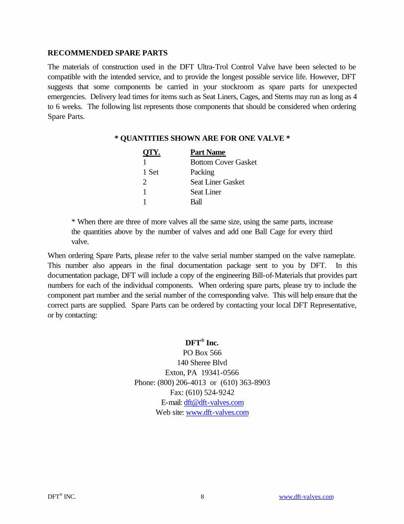
RECOMMENDED SPARE PARTS
The materials of construction used in the DFT Ultra-Trol Control Valve have been selected to be compatible with the intended service, and to provide the longest possible service life. However, DFT suggests that some components be carried in your stockroom as spare parts for unexpected emergencies. Delivery lead times for items such as Seat Liners, Cages, and Stems may run as long as 4 to 6 weeks. The following list represents those components that should be considered when ordering Spare Parts.
* QUANTITIES SHOWN ARE FOR ONE VALVE *
QTY. Part Name 1 Bottom Cover Gasket 1 Set Packing 2 Seat Liner Gasket 1 Seat Liner 1 Ball
* When there are three of more valves all the same size, using the same parts, increase the quantities above by the number of valves and add one Ball Cage for every third valve.
When ordering Spare Parts, please refer to the valve serial number stamped on the valve nameplate. This number also appears in the final documentation package sent to you by DFT. In this documentation package, DFT will include a copy of the engineering Bill-of-Materials that provides part numbers for each of the individual components. When ordering spare parts, please try to include the component part number and the serial number of the corresponding valve. This will help ensure that the correct parts are supplied. Spare Parts can be ordered by contacting your local DFT Representative, or by contacting:
DFT® Inc. PO Box 566
140 Sheree Blvd Exton, PA 19341-0566
Phone: (800) 206-4013 or (610) 363-8903 Fax: (610) 524-9242
E-mail: [email protected] Web site: www.dft-valves.com

DFT® INC. www.dft-valves.com 9
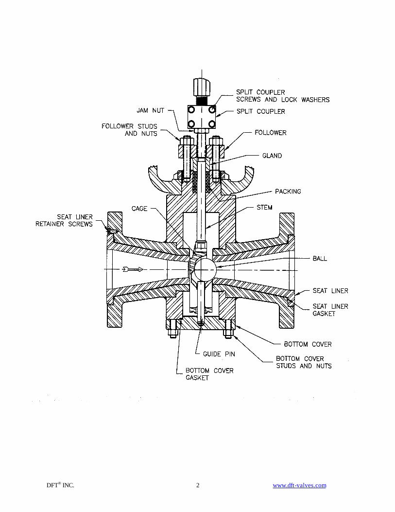
DISASSEMBLY
In the step-by-step instructions that follow, we have attempted to address disassembly in a thoroughly detailed manner. If at any time you should encounter difficulty, please notify your local DFT Valve Representative, or contact DFT at 610-363-8903.
Before the valve is disassembled, DFT recommends that the following points be reviewed:
1. Inspect the work area to see if hoist devices, safety barriers, scaffolding, etc., be required to complete the work. If so, this should be completed before disassembly begins. Make note of the various size and type tools that will be required and gather these together before work begins.
2. Review the valve assembly drawing to become more familiar with the valve and how the various components fit together.
NOTE: The valve assembly drawing is supplied as part of the Final Documentation Package when the valve order is shipped.
3. Check to be sure that all of the proper spare parts are on hand and are in good service condition.
4. Valves that are mounted in a vertical pipe (with flow down) and those valves that are mounted in an inverted position (with the valve stem down) will require special attention when removing the Ball and Cage. A piece of shim stock, of appropriate thickness and width, inserted into the valve between the Cage and downstream Seat, will allow the Ball to pass over the Seat for removal.
WARNING: MAKE SURE ALL THE PRESSURE IS RELIEVED, BOTH UPSTREAM AND DOWNSTREAM, BEFORE DISASSEMBLY WORK IS STARTED. FAILURE TO DO SO COULD RESULT IN PERSONAL INJURY. BEFORE ATTEMPTING TO SERVICE THIS VALVE, A POSITIVE METHOD OF VERIFYING THAT ALL LINE PRESSURE HAS BEEN RELIEVED SHOULD BE DEMONSTRATED.
5. The Ball, Cage, and Valve Stem may be accessed without removing the valve from the pipeline. Simply remove the Bottom Cover from the valve. To remove or replace the Seat Liner(s), it will be necessary to unbolt the valve from the pipeline.
6. The actuator will need to be uncoupled from the valve in order to facilitate maintenance. Refer to Appendix C for a detailed look at the Split Coupler connection. Loosen the Jam Nut on the bottom of the Split Coupler. Note that this is a left-hand thread.
7. Using the actuator, stroke the valve to the fully closed position.
8. Remove the four hex head screws that hold the Split Coupler together. With the flat blade of a screwdriver, pry the two halves of the Split Coupler apart and remove them from the valve and actuator stems.
9. Remove any positioner feedback linkages, position indicators, jam nuts, etc from the valve stem. Release the supply to the actuator and allow it to return to its failure position. Disconnect actuator supply, input signals, and all external connections (limit switches, solenoids, etc.).
DFT® INC. www.dft-valves.com 10
10. Loosen the valve stem Packing by removing the Follower Nuts from the Follower Studs. Slide the Follower and Gland off the end of the Valve Stem.
11. Mark the Body and Bottom Cover with adjacent marks so that the relative positions can be duplicated when the valve is reassembled.
12. Loosen and remove the Bottom Cover Nuts from the Bottom Cover. Using a screwdriver or other tool, pry the Bottom Cover away from the Valve Body. Set the Bottom Cover off to the side. Remove the Bottom Cover Gasket from the valve body and discard the gasket. It may make further disassembly easier if the Bottom Cover Studs are also removed.
13. If the valve is held in the closed position, pull up on the Valve Stem enough to let the Ball fall into the Cage. Push down on the top of the valve stem to drop the Stem, Cage, and Ball out of the valve. Remove the Ball from the Cage. Slide the Cage off of the Valve Stem. Remove the Packing from the top of the Valve Body.
NOTE: Disassembly to this point will allow visual inspection of the valve trim components. If replacement of the valve seat or other component is needed, continue to the end of this section.
14. If it is necessary to replace the Seat Liner, the valve will have to be removed from the piping. Unbolt the valve from the piping and slide the valve out.
15. The Seat liner may be pulled out from the flanged end of the valve. Remove any screws that are visible to retain the Seat Liner. If necessary, there are two holes in the flange to allow use of a screwdriver to pry the Seat Liner out of the flange.
16. There will be a Gasket located behind the flanged end of the Seat Liner. Remove the Gasket and discard it.
DFT® INC. www.dft-valves.com 11
PARTS INSPECTION AND REPAIR
Ball
(A) Examine the Ball for any evidence of damage. The Ball should be free of any visible defects. Note that it is not uncommon to see tracking marks (discoloration, but no physical damage) on the Ball resulting from contact with the cage, but this is normal and of no concern.
(B) Minor scratches and small cuts may be repairable by lapping. More severe cuts may be possible to repair by welding and lapping.
(C) All Stellite and ULTRA-loy Balls should be examined by the Liquid Penetrant method for detecting cracks. Cracks or porosity justify replacement.
NOTE: The condition of the Balls surface is very critical for maintaining a tight shut-off. If even the smallest of defects were detected, it would be better to contact the DFT Engineering Department for clarification than to put a defective Ball back into service.
Seat
(A) Examine the upstream and downstream seating surface for slight scratches, wiredraw, cavitation and flashing damage. Small indications of damage on the Seat face may be removed by lapping with a Seat Lapping Disc. Refer to Appendix A of this manual for instructions concerning lapping.
(B) Examine the Seat surface for evidence of a burnished ring from contact with the Ball. This ring should be continuous. Apply a very light film of Layout Bluing to the Ball and slightly rotate the Ball in the Seat. After the Ball is removed there should be a continuous ring in the Seat just slightly above the Seat bore. If the ring is not continuous, seat lapping will be required. Refer to Appendix A for proper instructions.
(C) The Downstream Seat may have a heavy burnish (dimple) at the 12 o’clock position. This is normal and should not be of concern as long as it does not extend into the sealing ring area of the seat face.
(D) All Stellite Seats should be examined by the Liquid Penetrant methods for cracks. Cracks or porosity justify replacement.
Generally, lapping can repair minor seat damage. However, severe damage will almost always require replacement.
DFT® INC. www.dft-valves.com 12
Cage
(A) Examine the T-slot corners for evidence of cracking. Also, check the T-slot ears for excessive wear. Solid investment cast Stellite Cages (Sizes 1/4” to 2”), should be inspected by the Liquid Penetrant method for cracks in the area of the T-slot.
(B) Examination of the four Ball Pads should reveal some evidence of wear (burnished dimples). This condition is normal and generally will not require any corrective action. Contact the DFT Engineering Department regarding any defects of a questionable nature at 610-363-8903.
NOTE: Extreme care should be taken when fitting the Cage to the Stem head. A sliding fit between the Stem head and Cage T-slot is required for the assembly to function properly. However, when pulling on the Stem it should not be loose at the Cage T-slot. If it is necessary to shorten the head of the Valve Stem, it should be done with a flat file or an air grinder while the stem is rotated in a lathe or by other means. The spherical radius on the end of the Stem must be maintained.
Stem
(A) Examine the Stem threads for possible damage and clean thoroughly.
(B) Examine the area of the Stem that travels through the packing for possible scratches and/or galling. Small scratches (less than .003” deep) can be removed by polishing with emery cloth and a lightweight machine oil. This should only be attempted on a lathe, and should be blended into the surrounding surface.
(C) Examine the Stem T-head for evidence of heavy wear or cracks.
(D) Examine the Stem on a flat surface to determine if it has been bent.
(E) Stems that are severely scratched, bent or have damage to the T-head should be replaced.
Guide Pin
(A) The Guide Pin should be checked to determine if it is bent. Bent Guide Pins should be straightened or replaced.
(B) A slight burnish or dimple may be detectable on the very tip of the Guide Pin. This is normal and generally will not require repair.
(C) The clearance between the top of the Guide Pin and the Ball is critical. The method of checking and adjusting this dimension is addressed in Appendix B of this manual.
(D) Severe damage to the Guide Pin is usually a result of valve over-stroke. Carefully setting the valve stroke in accordance with the instructions set forth in Appendix C of this Maintenance Manual will eliminate the chances of damaged or broken Guide Pins.
DFT® INC. www.dft-valves.com 13
Bottom Cover
(A) Typically, the Bottom Cover will not require extensive repair during the service life of the valve. Examine the Gasket face for scratches or evidence of other types of damage. Small defects may be removed by polishing with emery cloth and lightweight machine oil, while turning the Bottom Cover in a lathe. Larger defects may require machining; however, tolerances on this component are critical, and machining should not be done without first contacting DFT at 610-363-8903.
Body
(A) Examine the inside of the Valve Body to look for signs of wear or damage. If damage is detectable, it may be necessary to repair the Body.
(B) Examine the pockets of the endpieces where the Seat Liner Gaskets are located. These areas should be free of scratches and erosion.
(C) Examine the Bottom Cover Gasket sealing pocket for defects. This area should be clean and free of all obvious defects. Small scratches, nicks or scrapes can be removed by lightly polishing with emery cloth and lightweight machine oil.
The Body is the primary pressure vessel; therefore, the condition of this component is very critical. No defect, of any type, should go unquestioned. If an area has questionable defects contact the DFT Engineering Department at 610-363-8903.
Gaskets
To ensure positive sealing, it is recommended that all Gaskets that are removed during disassembly be replaced prior to reassembly.
Stem Packing
NOTE: In order to prevent external emissions of process fluid, it is recommended that all Valve Stem Packing be replaced upon valve re-assembly.
When installing new Packing, make certain the Stem and Valve Body Packing Chamber are thoroughly cleaned to insure the best possible seal. Install each new Packing Ring separately, pushing each Ring to the bottom of the chamber. If Split Packing Rings are being used, make certain the cuts of each consecutive Ring are staggered.

DFT® INC. www.dft-valves.com 14
REASSEMBLY
In most cases, reassembly is the reverse of disassembly. If at any time during reassembly you should encounter difficulty, please notify your local DFT Representative, or contact DFT at 610-363-8903. We will respond immediately to your questions.
1. The most important consideration in the reassembly of the DFT Ultra-Trol Control Valve is cleanliness. All flaky rust and dirt should be removed with a suitable solvent. All sealing and seating surfaces should be thoroughly inspected and cleaned.
2. While cleaning the parts, take time to examine them for nicks, dings, or burrs, which could possible create problems during reassembly. Refer to the previous section Part Inspection and Repair for recommendations as to what to look for, and how to correct the defect.
3. All threaded parts should be thoroughly cleaned with a suitable solvent and a wire brush. All threaded parts should then be re-lubricated with a high temperature product such as LOCTITE Nickel Anti-Seize or NEVER-SEEZ.
CAUTION: When applying anti-seize during reassembly, exercise care so that the anti-seize does not come in contact with the gaskets, or gasket seating surfaces.
4. Take time to look into the Valve Body for any loose debris (i.e.: weld rods, boards, rags, etc.) which may have fallen into the valve. Foreign objects in the pipe can render a perfectly rebuilt valve useless, as well as cause irreparable damage to the valve.
5. Dry fit the Seat Liner into the Valve Body flange. The Seat Liner should slip freely into the pocket, and should turn freely when slightly rotated.
6. Apply a proper seal lubricant (i.e.: White Lithium Grease for Spiral Wound Metal Gaskets) to the gasket pocket in the Valve Body flange. This will help hold the Gasket in place when the Seat Liners are installed into the Valve Body.
7. With the Gasket in place, insert each Seat Liner into the Valve Body flange, and rotate it slightly to insure it is not cocked. Replace any retainer screws that were used to hold the Seat Liner in the Valve Body.
8. Slide the end of the Valve Stem into the T-slot of the cage. Check the fit between the Cage and the Valve Stem; this fit is very critical. If either the Valve Stem or the Cage was replaced, it may be necessary to fit the Valve Stem to the Cage. There should be a sliding fit between the knob end of the Stem and T-slot of the Cage. The Valve Stem should be free to slide within the Cage, but excess play should be avoided. If it is necessary to shorten the head of the Valve Stem, it should be done with a flat file or an air grinder while the Stem is rotated in a lathe. The spherical radius on the end must be maintained.
9. Carefully place the Ball into the Cage. Push the threaded end of the Valve Stem up through the valve body and through the packing gland. Take care not to scar the Stem as it passes through the packing gland. Take care that the Cage and Ball slide smoothly between the seats inside the valve body. Push the Valve Stem all the way to the full open position.
DFT® INC. www.dft-valves.com 15
CAUTION: It is very important that the Ball and Cage be properly oriented. The open side of the Cage must face downstream so that the Ball can freely move into the downstream seat.
NOTE: Valves mounted in a vertical pipe, with flow down, will require special care when installing the Stem, Cage and Ball assembly. It is suggested that a piece of shim stock, of suitable thickness, be placed into the valve on the Downstream Seat. This will hold the Ball in place until it passes over the Seat, at which time the shim material should be removed.
10. Apply a liberal coating of lubrication to the new Bottom Cover Gasket and place the Gasket in its groove in the bottom of the Valve Body.
11. If a new Guide Pin was installed in the Bottom Cover, refer to Appendix B for Guide Pin adjustments before installing the Bottom Cover.
12. Lining up the matching marks between the Valve Body and the Bottom Cover, set the Bottom Cover in place against the bottom of the Valve Body. Make sure that the Guide Pin engages the hole in the bottom of the Cage. Making sure that the Bottom Cover is fully seated against the Valve Body, replace the Bottom Cover Nuts and torque them down according to the values recommended in Appendix D.
13. Move the Valve Stem up and down a few times to ensure that it moves freely and is not bound.
14. Install new Packing onto the Valve Stem. Install the rings one at a time to ensure that they are properly seated in the packing chamber. If the packing contains split rings, ensure that the cuts in consecutive packing rings are staggered around.
15. Slide the Packing Gland and Follower onto the Valve Stem. Screw the Follower Nuts onto the Studs to hold the Packing, Gland, and Follower in place, but do not torque down the Nuts at this time. Using your hand, manually push down on the valve stem to ensure that the valve is in the fully closed position and that the Ball is firmly positioned in the seat.
16. Install the Actuator.
17. Screw the Jam Nut fully onto the Valve Stem. Remember that this is a left-handed thread. Place the position indicator and any feedback brackets onto the stem.
18. Referring to Appendix C, install the Stem Split Coupling and adjust the Valve Stroke.
19. Torque down the valve stem Packing. The torque value is dependent on both the size of the packing and the operating pressure of the valve. Refer to the Production Check Sheet that is found in the documentation package supplied by DFT when the valve was originally shipped.
20. Restore all external sources (i.e. Power Supply, Signal Supply, etc.) and actuate the valve through several cycles. The valve should operate smoothly, and should freely stroke from the fully closed position to the fully open position.

DFT® INC. www.dft-valves.com 16
Appendix A SEAT LAPPING INSTRUCTIONS
Lapping can frequently salvage Seats that have been in service, but have only slight damage.
1. New seats supplied from the DFT factory have already been lapped prior to shipment.
2. To check a seat, set the Seat Liner down on a flat table with the flanged portion of the liner facing down and the seat portion sticking up. Apply a light film of Layout Bluing (i.e.: DYKEM, Hi-Spot Blue No. 107) on the Ball, and position the Ball in the Seat. Applying light pressure by hand slightly rotate the Ball sufficiently to transfer Bluing to the Seat. Examine the Seat; there should be a thin continuous ring of Bluing all around the Seat circumference near the Seat bore. If the bluing ring is not consistently continuous, the Seat will have to be lapped.
3. Once a continuous Bluing Ring is achieved, the accuracy should be verified by one final check.
(A) Thoroughly clean the Ball and Seat with a suitable solvent. (B) Insert the Ball into the Seat. (C) While applying pressure to the Ball by hand, slightly rotate the Ball in the Seat. (D) Remove the Ball. (E) The Seat should have a bright burnished continuous ring all around the Seat Ring near the Seat
bore. Evidence of a bright continuous ring will insure a good seating surface.
Slightly Damaged Seats
Valve leakage may be due to minor damage to the Seat. This damage may be correctable by lapping rather than replacement with a new Seat. Generally, cuts, scratches and damage not more then .005” deep can be removed by lapping. More extensive damage may warrant seat replacement.

DFT® INC. www.dft-valves.com 17
Recommended Lapping Procedure
WARNING: THE BALL MUST NEVER BE USED TO LAP THE SEAT. USE A LAPPING TOOL AS DESCRIBED BELOW.
Notes:
1. Multiply the dimensions shown by the valve size (i.e. 2 for 2” valve) to obtain proper dimensions for the lapping tool.
2. It is recommended that hard porous material such as Gray Iron, Bronze, or Brass be used for making the lapping disc.
3. Note that the seat angle of 40° is for “standard” seat bores only. If your valve has a special port size, the seat angle is probably different than 40°. Consult DFT for the appropriate angle dimension.
1. Using a hard porous material (Gray Iron or Bronze), machine a Lapping Disc as shown above.
2. Apply double-faced tape to the Lapping Disc, and then apply cut segments of emery cloth to the tape. NOTE: A 120 or heavier grit of paper may be used for a severely worn Seat, or on a Seat that appears will require extensive lapping. Alternately, use a coarse grade of lapping compound. We recommend that a Grade G (80 grit) compound be used for this alternate procedure.
3. Place the Lapping Disc into the Downstream Seat, and rotate it back and forth, through a small arc, several times. Lift the Lapping Disc out of the Seat, rotate it approximately one quarter of a turn, and repeat. Continue this cycle until a full, straight conical surface is obtained. Then remove all double sided tape and emery cloth from the Lapping Disc and clean the Disc thoroughly with a suitable solvent.

DFT® INC. www.dft-valves.com 18
4. The lapping sequence continues in the same manner using progressively finer grit lapping compounds, until a suitable seating surface finish is obtained. At DFT, FEL-PRO, Clover Lapping Compounds are used for lapping Valve Seats:
-The initial lap is completed using Grade G - 80 grit. -The second lap is completed using Grade D - 180 grit. -The third lap is completed using Grade 1A - 320 grit. -The finishing lap is completed using Grade 4A - 600 grit.
Each time a change is made to the next grit, the Seat and Lapping Disc must be thoroughly cleaned in a suitable solvent.
5. As a final check, apply bluing to the Ball and visually inspect the resulting ring in the Seat for a solid continuous ring as described above.

DFT® INC. www.dft-valves.com 19
Appendix B GUIDE PIN ADJUSTMENT
CAUTION: Failure to properly set the Guide Pin clearance may restrict the Valve closing, and cause damage to the Guide Pin.
To facilitate proper adjustment, all replacement Guide Pins shipped from DFT will be furnished slightly longer and with a larger diameter than is required. It will be necessary to adjust the length after the guide pin is installed in the Bottom Cover.
1. The Guide Pin is shrink fit into the Bottom Cover. Carefully measure the diameter of the base of the Guide Pin as well as the hole in the Bottom Cover. If necessary, machine the Guide Pin to +.002” larger than the hole in the Bottom Cover.
2. Place the Guide Pin in liquid nitrogen to shrink it. Leave the pin in the liquid nitrogen until the bubbling stops, approximately 10-15 minutes.
3. While the guide pin is boiling in the liquid nitrogen, use a heat gun on the Bottom Cover to warm it up. Concentrate the heat in the area of the Bottom Cover hole.
4. Caution: use proper protective clothing and safety equipment while handling the liquid nitrogen and heat gun. Once the Guide Pin has finished boiling and the Bottom Cover is warm, carefully install the Guide Pin in the Bottom Cover hole. Make sure that the Guide Pin is fully seated in the Bottom Cover hole. Allow the temperature to stabilize.
5. With the Bottom Cover still removed from the valve body, place the ball into the seat and take a measurement from the bottom of the valve body to the bottom of the seated ball as shown in the Figure. This is measurement ‘A’. Next, measure from the distance from the top of the Guide Pin to the base of the Bottom Cover. Record this as measurement ‘B’. Once the valve is assembled, the proper clearance between the Guide Pin and the ball is found in the Table listed below.
6. Adjust the length of the Guide Pin until ‘B’=‘A’-Guide Pin Clearance. To shorten the Guide Pin, use a flat file or an air grinder. NOTE: The blunt spherical radius of the Guide Pin tip must be maintained.
4.
DFT® INC. www.dft-valves.com 20
Guide Pin Clearance Dimensions
Valve Size
Required Clearance
1/4” .010” to .015” 1/2” to 1” .020” to .030”
1-1/4” to 2” .025” to .035” 2-1/2” to 6” .030” to .045” 8” and Larger .040” to .060”

DFT® INC. www.dft-valves.com 21
Appendix C SPLIT COUPLER ADJUSTMENT
DFT Control Valves use a split coupling Stem Connector for connecting the Valve Stem to the Actuator Shaft. This type of connector is common for Control Valves that are actuated by a Diaphragm or Piston style Actuator.
The DFT Split Coupler features left hand and right hand threads for final adjustments during assembly. The Stem Thread on the Valve Stem is a left-handed thread; whereas, the Actuator Shaft Thread is usually a right handed thread. If the Stem connection on your valve is different than that described, contact DFT Engineering Department, for special instructions. By turning the Split coupling clockwise the Stem and Actuator Shaft are separated, and by turning the Coupling counter-clockwise they are pulled together. The lengthening and shortening effect changes the relationship of the Ball and Cage to the Seat.
NOTE: All DFT Control Valves are adjusted at the factory prior to shipment and should not require resetting until the valve is disassembled. If it is necessary to change the valve setting, the instructions in this section will guide you through the proper steps. Failure to properly adjust the Valve Stroke and Split Coupling could result in valve damage.
Removal of the Stem Split Coupling
WARNING: VERIFY THAT THE VALVE STEM AND ACTUATOR SHAFT ARE NOT UNDER TENSION. IF THE VALVE IS EQUIPPED WITH A FAIL OPEN ACTUATOR, THE STEM AND ACTUATOR SHAFT WILL BE IN TENSION. IT IS THEREFORE RECOMMENDED THAT THESE VALVES BE HELD IN THE CLOSED POSITION (OR SOME INTERMEDIATE POSITION) WITH THE POWER SOURCE WHILE REMOVING THE SPLIT COUPLING.
WARNING: FAILURE TO PROPERLY RELIEVE THE STEM TENSION COULD RESULT IN PERSONAL INJURY.
DFT® INC. www.dft-valves.com 22
1. Loosen the Jam Nut under the Split Coupling. Note that this is a left-handed thread.
2. Remove the Hex Head Bolts that are holding the two halves of the Split Coupling together.
3. With the flat blade of a screwdriver, pry the two halves apart and remove them from the Stem and Actuator Shaft.
4. Remove the Position Pointer and any other actuating levers or feedback linkages that may be present. Thread the Stem Jam Nut off of the Valve Stem.
Installation of the Split Coupling
1. Prior to assembly, take time to examine the threads on the Valve Stem and Actuator Shaft for possible damage. The threads should be clean and free of defects.
2. Stroke the valve manually to insure the Ball, Cage and Stem are operating freely. Manually push the Stem to the fully closed position. Extreme force will not be required; however, sufficient force should be applied to insure the Ball is firmly seated.
3. Apply a high temperature anti-seize thread lubricant to the Stem thread and the Actuator Shaft thread. Thoroughly clean the threads of the two Split Coupling halves and apply thread lubricant.
4. Install the Jam Nut, Position Pointer and any other actuating levers onto the Valve Stem. Screw the Jam Nut all the way down. Remember that this is left hand thread.
5. Carefully examine the threads in the Split Coupling halves to insure the right hand threads mate with the Actuator Shaft and the left hand threads mate with the Valve Stem threads.
6. With the Actuator Shaft in the fully extended position, fit one of the Split Coupling halves onto the Shafts.
NOTE: It is very important that the actuator is in the fully extended position, or valve failure could result.
7. The fit-up of the Stem Split coupling to the Stem and Actuator Shaft should be made so there is an equal distribution of thread engagement on both connecting shafts. To insure the threads are properly seated, it may be necessary to slightly rotate the Coupling half while pulling the Coupling half into the threaded shafts. Extreme care should be taken to insure the Valve Stem position is not changed during this fit-up.
8. Install the other Coupling half and secure with the Hex Head Bolts. Do not tighten the bolts at this time.
DFT® INC. www.dft-valves.com 23
Setting the Valve Stroke
1. With the Split Coupling Hex Head Bolts loose and the valve in the closed position, try to rotate the Stem Split Coupling clockwise. This will increase the spread between the Stem and Actuator Shaft and insure that the Cage wedge is in slight contact with the Ball.
Caution: Do not apply more force than can be applied by hand; on larger valves where a wrench may be required, do not apply more than 10-15 ft./lbs. torque. DO NOT OVER WEDGE.
2. Now rotate the Stem Split Coupling approximately 1/2 to 1 full turn counter-clockwise, thereby releasing the Cage wedge load.
3. Securely tighten the Split Coupling Hex Head Bolts. Tighten the jam nut up against the bottom of the Split Coupler.
4. Stroke the valve again to insure smooth operation throughout the entire stroke range.
5. Any accessory instrumentation (i.e. - Positioner, Limit Switches, etc.) should now be adjusted and calibrated based on the full stroke of the valve.

DFT® INC. www.dft-valves.com 24
Appendix D BOLTING TORQUE
A torque wrench should be used for tightening the pressure vessel bolting used on the DFT Valves.
FASTENER SIZE (Inches)
THREADS / INCH (UNC) TORQUE VALUE -(Ft-Lbs)
1/2 13 30 9/16 12 45 5/8 11 60 3/4 10 100 7/8 9 160 1 8 245
1-1/8 8 355 1-1/4 8 500 1-3/8 8 680 1-1/2 8 800
These values are based on using a high temperature thread lubricant. The threads as well as the fastener head bearing surface must be lubricated.
Fastener torque values should be applied in incremental steps. Apply a steady, even pull to the torque wrench handle and follow a staggered star pattern when torquing.
NOTE: To guard against leakage, it is good practice to check and verify the torque for all pressure vessel bolting once the valve is brought up to normal operating pressure and temperature.
Printed in the U.S.A. Copyright 2002, DFT® INC., All Rights Reserved 5/29/2002 Rev. 2