maintenance manual lh 350 flight helmethelicopterhelmet.com/msa gallet lh 350 helicopter...
TRANSCRIPT

CONFIDENTIAL INDUSTRY
Ref : 180722 – PP0200175 ind00 1/18
MAINTENANCE MANUAL
LH 350 FLIGHT HELMET

CONFIDENTIAL INDUSTRY
Ref : 180722 – PP0200175 ind00 2/18
Table of Contents
Topic Page Table of Contents 2/19
WARNING 3/19 DESCRIPTION OF HELMET 4/19 GUARANTEE 5/19 PREAMBLE 6/19 CHINSTRAP 7/19 CLOTHING 8/19 OUTER VISOR 9/19 INNER VISOR 10/19 NVG HARD COVER 11/19 THE INNER IMPACT CAP 12 and 13/19 NECK PAD 14/19 ACCESS TO ELECTRONIC CARD 15/19 ELECTRONIC CARD 16/19 INSPECTION VERIFICATION 17/19 AND MAINTENANCE REQUIREMENTS MANDATORY INSPECTION 18/19 AND REPLACEMENT CRITERIA

CONFIDENTIAL INDUSTRY
Ref : 180722 – PP0200175 ind00 3/18
WARNING
Thank you for placing your trust in MSA products. Please read these instructions carefully before using your helmet. Failure to observe these instructions could reduce the amount of protection your helmet provides. Your helmet will only provide maximum protection if all of the MSA components are used with it. Furthermore, any change made to your helmet or failure to use one of the original helmet components will imply improper use of the eq uipment, and will discharge MSA of any liability. In an ongoing effort to improve its products, MSA hereby reserves the right to alter them at no notice. To guarantee sufficient protection, the helmet must be adapted and adjusted to the wearer’s head size. Your helmet is desig ned such that the pressure built up when it is knoc ked is absorbed by the partial destruction or damage to the outer a nd inner cap; even if such damage is not immediately apparent, we recommend replacing an y helmet which has taken a considerable impact. The user’s attention is also drawn to the dangers o f modifying or removing any of the original components of the helmet, apart from any m odification or removal recommended by the helmet manufacturer. Under no ci rcumstances should helmets be adapted for attachment of accessories by any means not recommended by the helmet manufacturer. Do not apply any paint, solvents, adhesives or self -adhesive labels, other than those recommended by the helmet manufacturer’s instructio ns.
The MSA LH 350 flying helmet is designed only for helicopter pilots and crew members. It ensures a maximum comfort and protection. Available in three sizes to fit head measuring between 52 cm to 64 cm. It incorporates two visors; and could receive a wide range of communication systems and Night Vision Goggles supports, available to order. Please contact us for details. Each helmet is individually serial numbered to ensure correct identification of the helmet and a correct record of the service life history of the helmet.
Checks should be made following any apparent impact , carried out by our maintenance department or a specialist.

CONFIDENTIAL INDUSTRY
Ref : 180722 – PP0200175 ind00 4/18
LH 350 F L I G H T H E L M E T DESCRIPTION OF HELMET The LH350 helmet shell is made of :
• A one-piece shell in high performance composite fibers. The shell covers a large head protection zone.
• An expanded polystyrene inner padding for impact absorption. It is covered with a velvet lining for the user's comfort.
• Custom fit pads are used to fit the helmet to the users headform. The outside coating is flame retardant. The inner lining is made up of two comfort spacers : the T shaped spacer and the neck spacer each of these spacer can be personalized with different foam in 3 thickness (4mm, 8mm and 12mm) which make it possible to obtain a perfect fit for the user's head form. The lining elements are made up of different thickness foam inserts covered in a ‘patented‘ wicking material to draw moisture away from the users skin in hot and humid climates and ensure the user’s comfort. These two comfort spacers are attached inside the shell by Velcro strips. Adaptation to the user's head form is made by choosing the foam thickness inside each spacer. Two protective visors manufactured are fitted to the LH350 :
• Both visors are mounted on the outside of the helmet shell and fully protected by the hard cover
• Both visors can be adjusted to suit the users requirements. The acoustic protection system is made up of :
• Two injection molded thermoplastic earcups, with a recess to accommodate the communication earphones.
• Two earseals for comfort, ergonomically shaped. • Specific acoustic foam.
These earcups ensure correct acoustic protection and are fixed inside the shell by Velcro spacers. The chinstrap is made of a synthetic fire-proof fibre strap with a clipping buckle. A leather chinstrap covers the strap to ensure user’s comfort at the chin. 8 A helmet protective bag. Serial Number, Helmet Log Card and Modification Rec ord. Every MSA flight helmet is supplied with a helmet log card recording the manufacturing and model details of the helmet, in addition to recording modifications and Level 3 repairs to the helmet. Each helmet is individually serial numbered to ensure correct identification of the helmet and a correct record of the service life history of the helmet.

CONFIDENTIAL INDUSTRY
Ref : 180722 – PP0200175 ind00 5/18
G U A R A N T E E All of our models, accessories, and spare parts are meticulously inspected before leaving the factory. MSA helmets and their options are guaranteed for one year from the date of purchase. Guarantee provides for parts and labor repair or replacement of the helmet and components arising from any mechanical or electrical failure or defect which may occur during normal operating conditions as described in the helmet Instruction Manual supplied with each helmet.

CONFIDENTIAL INDUSTRY
Ref : 180722 – PP0200175 ind00 6/18
PREAMBLE Important : for any repair install the helmet at least on the helmet protecting bag
Necessary tools : - 20, 15 and 10 TORX key
- 7 mm combination wrench
- 2 mm hexagonal screw driver
- Flat blade screwdriver
- Threadlocking low strength (LOCTITE 222 or equivalent )

CONFIDENTIAL INDUSTRY
Ref : 180722 – PP0200175 ind00 7/18
1. Chinstrap: Tools: 20 and 15 TORX keys, 7 mm combination wrench and flat blade screwdriver. Dismantling duration: 1 minute. Mounting duration: 2 minutes.
Open the chinstrap.
4 points chinstrap disassembly
Left and right chinstrap dismantle:
1 front fixation points: unscrew the outer screw with the 20 key TORX while maintaining inner helmet nut with 7 mm combination wrench (remove the nut cap with the screw driver before ),
2 rear fixation points : unscrew the inner helmet screw with the 15 TORX key.
Proceed in the reverse order to reassemble.
Warning : Apply Threadlocking low strength on the inner TORX screw back fixation point before mounting.
When removing the chin-cup; check that the buckle is correctly positioned, the opened side of the buckle towards the outside of the helmet.
20 TORX key
7 mm combination wrench
15 TORX key
1
Inside detail
Inside detail 2

CONFIDENTIAL INDUSTRY
Ref : 180722 – PP0200175 ind00 8/18
2. Clothing: Tools: none. Dismantling duration: 20 seconds. Mounting duration: 45 seconds. LH 350 helmet includes 2 comfort parts and spacers: • 1 adjustable, comfortable T-shaped spacer with 4 mm, 8mm and 12mm thick foam,
• Comfort neck spacer with 4 mm, 8mm and 12mm thick foams,
• Self-gripping spacers for ear cup adjustment.
Those elements are fixed inside the helmet by self gripping tapes.
When changing the foam in the T shaped spacer and in the comfort neck spacer, insure that the chosen foams are well positioned. Check the presence of the trapezoid insert with the comfort neck spacer.
4mm thickness foam (no hole)
8mm thickness foam (1 hole)
12mm thickness foam (2 holes)
CONFIDENTIAL INDUSTRY
Ref : 180722 – PP0200175 ind00 9/18
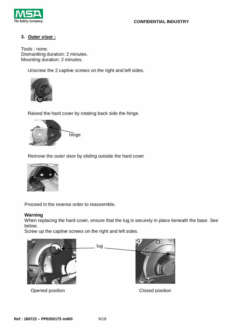
3. Outer visor : Tools : none. Dismantling duration: 2 minutes. Mounting duration: 2 minutes.
Unscrew the 2 captive screws on the right and left sides.
Raised the hard cover by rotating back side the hinge.
Remove the outer visor by sliding outside the hard cover
Proceed in the reverse order to reassemble. Warning When replacing the hard cover, ensure that the lug is securely in place beneath the base. See below. Screw up the captive screws on the right and left sides.
lug
Opened position
Closed position
hinge
CONFIDENTIAL INDUSTRY
Ref : 180722 – PP0200175 ind00 10/18
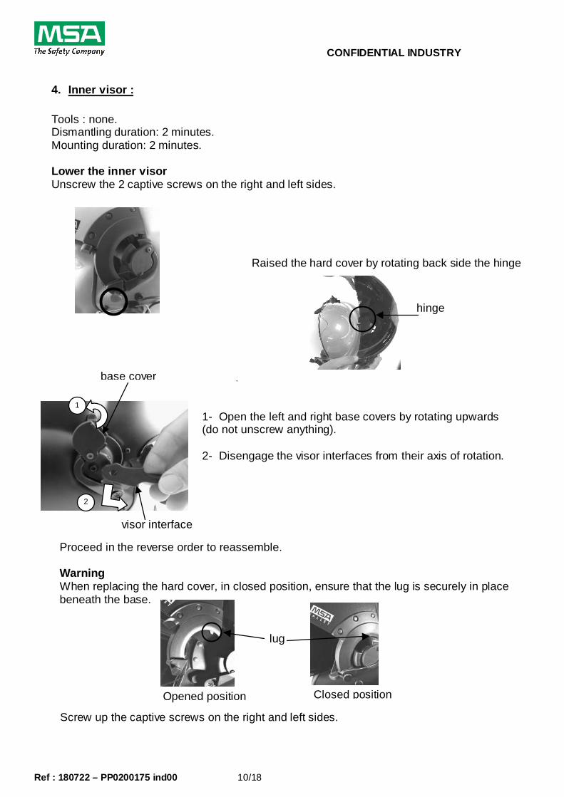
4. Inner visor : Tools : none. Dismantling duration: 2 minutes. Mounting duration: 2 minutes. Lower the inner visor Unscrew the 2 captive screws on the right and left sides.
Raised the hard cover by rotating back side the hinge
.
1- Open the left and right base covers by rotating upwards (do not unscrew anything). 2- Disengage the visor interfaces from their axis of rotation.
Proceed in the reverse order to reassemble.
Warning When replacing the hard cover, in closed position, ensure that the lug is securely in place beneath the base.
lug
Screw up the captive screws on the right and left sides.
1
2
visor interface
base cover
hinge
Opened position Closed position

CONFIDENTIAL INDUSTRY
Ref : 180722 – PP0200175 ind00 11/18
5. NVG hard cover : Tools : 2 mm ALEN screw driver. Dismantling duration: 2 minutes. Mounting duration: 3 minutes. Unscrew the 2 captive screws on the right and left sides.
Unscrew the 2 ALEN screws on the hinge.
Proceed in the reverse order to reassemble.
Warning When replacing the hard cover, ensure that the lug is securely in place beneath the base. See below. .
lug
Screw up the captive screws on the right and left sides
Opened position
Closed position

CONFIDENTIAL INDUSTRY
Ref : 180722 – PP0200175 ind00 12/18
6. The inner impact cap: Tools : 15 TORX key Dismantling duration: 5 minutes. Mounting duration: 8 minutes.
To dismantle the inner cap : - remove all the comfort parts (T spacer, neck spacer), - remove the two ear cups, - dismantle the chinstrap (see chap. 2),
Remove the stud
Remove the inner left and right inner padding
15 TORX key
Remove the blocking pieces on each side of the shell
Inner detail
Remove the neck pad

CONFIDENTIAL INDUSTRY
Ref : 180722 – PP0200175 ind00 13/18
Pull the rear side of the inner impact cap to release the inner cap of the shell
Then pull the front part of the inner cap
Proceed in the reverse order to reassemble. Warning for neck pad mounting see § 7.
CONFIDENTIAL INDUSTRY
Ref : 180722 – PP0200175 ind00 14/18
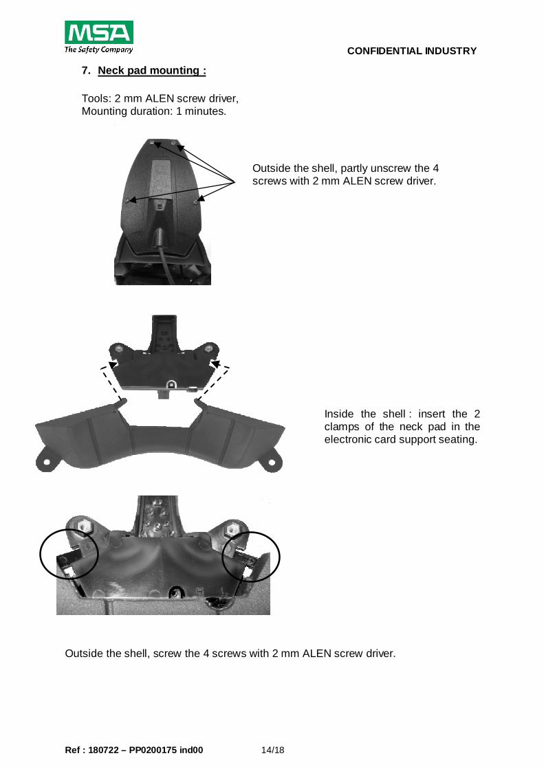
7. Neck pad mounting :
Tools: 2 mm ALEN screw driver, Mounting duration: 1 minutes.
Inside the shell : insert the 2 clamps of the neck pad in the electronic card support seating.
Outside the shell, screw the 4 screws with 2 mm ALEN screw driver.
Outside the shell, partly unscrew the 4 screws with 2 mm ALEN screw driver.

CONFIDENTIAL INDUSTRY
Ref : 180722 – PP0200175 ind00 15/18
8. Access to the electronic card: Tools: 2 mm ALEN screw driver, 15 TORX key Dismantling duration: 3 minutes. Mounting duration: 4 minutes. Proceed in the reverse order to reassemble.
Remove the cover to have access to the electronic card
Unscrew the cable maintain screw with the 15 TORX key.
Unplug the cable plug on the card.
Remove the cable for a complete access to the electronic card.
Unscrew the 4 screws with 2 mm ALEN screw driver

CONFIDENTIAL INDUSTRY
Ref : 180722 – PP0200175 ind00 16/18
9. Electronic card
Tools : flat blade screwdriver Dismantling duration: 1 minute. Mounting duration: 2 minutes. See § 8 for access to electronic card. Unplug the 3 JST plugs Left earphone Right earphone Microphone.
Pull out the card with the flat
blade screwdriver screw driver as shown.
Proceed in the reverse order to reassemble.
Left earphone
Right earphone
Microphone

CONFIDENTIAL INDUSTRY
Ref : 180722 – PP0200175 ind00 17/18
10. Inspection, Verification and Maintenance Requi rements. The MSA range of flight helmets is designed as a modular solution to meet the requirements of helicopters pilots and crew members. The helmet is designed to require minimal maintenance intervention and recommended servicing or repair is on an ‘ON CONDITION BASIS’. Accordingly, a full periodic service program is not recommended or required in support of the LH350 flight helmets. Listed below is a recommended schedule of servicing which may be adopted by users of the LH350 flight helmet. MSA do not recommend a program of servicing which involves complete disassembly of the helmet on a periodic basis. The helmet is designed and engineered to enter and remain in operational service until such time as corrective maintenance is required for unserviceabilities of the helmet shell, visor system or communications package. Inspection, Verification and Maintenance Matrix: Basic Controls*
Before each flight
Cleanness and working of the visors Yes Attendance of the comfort pads Yes Chinstrap status working and fixation points Yes Functional check of communications Yes Hard cover fixation points Yes Fixation points of electronic box Yes Periodic Controls* Every: Tightening and working of: inner and outer visors, communication system, anti cable tear-out system
3 months
State of the visors and fixation system 3 months State of the pads 3 months State of comfort ear set 3 months State of the chin strap and working of the locking system 3 months State of the shell (single impact use) 3 months Cleaning as specified in User Manual 2 months Major Spare Parts Replacement* (Forecast Replacemen t Interval)
Every:
Inner visor 5 years Outer visor 5 years TSHAPED SPACER NECK PAD SPACER 2 years Comfort ear seal Chinstrap 2 years Inner cap 5 years Shell 10 years
Note: Inspection criteria based on a standard 200 h ours annual usage period.

CONFIDENTIAL INDUSTRY
Ref : 180722 – PP0200175 ind00 18/18
11. Mandatory Inspection & Replacement Criteria This section details the mandatory actions and inspections required when a helmet suffers a confirmed impact incident OR when routine maintenance reveals damage consistent with an impact incident. Mandatory actions and inspection requirements are detailed in the matrix listed below. Mandatory Inspection & Replacement Criteria Matrix:
ACTION TO BE TAKEN
Condition
Mandatory Replacement Requirement – Confirmed Impact:
The helmet shell is designed for single impact use ONLY. • The helmet shell and protective integrity is considered
compromised following a confirmed impact; • The helmet shell is to be removed from service immediately
following a confirmed impact and rendered unusable or destroyed.
CONFIRMED
IMPACT
Mandatory Inspection Requirement Unconfirmed Impact:
Where damage consistent with helmet impact is displayed. The helmet is to be inspected for the following;
• Indentation, cracking or deformation of the composite fibers shell and hard cover;
• Damage to the composite shell construction including cut or frayed fibers;
• Removal of outer protective coating resulting in the degradation of the gel coating exposure of composite fibers;
• Dislodgement or deformation of the impact cap; • Damage to the visor adjustment and rotation mechanisms; • Damage to the chinstrap webbing, buckle assembly and
fixation points; • Inspection to be recorded on helmet log card.
If damage consistent with an impact is confirmed - Mandatory Replacement is required.
Mandatory Inspection if
Impact Suspected
User & Operational Maintenance Responsibility All helmet users and operational maintenance units are responsible for reporting known or suspected impact incidents and damage to helmet shells. Operational maintenance units are responsible for ensuring the required inspection criteria are met in assessing the continued serviceability of the helmet. Failure to withdraw a damaged helmet shell from operational use will relieve MSA from any liability in the event of helmet failure.