management center emc data domain network settings 98 configuring routes 101 upgrading dd management...
TRANSCRIPT

EMC® Data Domain®
Management CenterVersion 1.3
User Guide302-001-661
REV 01
Copyright © 2012-2015 EMC Corporation. All rights reserved. Published in USA.
Published May, 2015
EMC believes the information in this publication is accurate as of its publication date. The information is subject to changewithout notice.
The information in this publication is provided as is. EMC Corporation makes no representations or warranties of any kind withrespect to the information in this publication, and specifically disclaims implied warranties of merchantability or fitness for aparticular purpose. Use, copying, and distribution of any EMC software described in this publication requires an applicablesoftware license.
EMC², EMC, and the EMC logo are registered trademarks or trademarks of EMC Corporation in the United States and othercountries. All other trademarks used herein are the property of their respective owners.
For the most up-to-date regulatory document for your product line, go to EMC Online Support (https://support.emc.com).
EMC CorporationHopkinton, Massachusetts 01748-91031-508-435-1000 In North America 1-866-464-7381www.EMC.com
2 EMC Data Domain Management Center 1.3 User Guide

7
DD Management Center Overview 11
Introducing DD Management Center.............................................................. 12Features of DD Management Center...............................................................12Differences between DD Management Center and DD System Manager......... 13Backing up and restoring in a VMware environment...................................... 13
Getting Started 15
Logging in and out of DD Management Center............................................... 16Logging in to DD Management Center...............................................16Logging out of DD Management Center.............................................16
Understanding RBAC in DD Management Center............................................16Viewing DD Management Center page elements............................................ 17Navigating a DD Management Center page.................................................... 18Organizing the dashboard............................................................................. 18
Adding tabs..................................................................................... 19Adding widgets................................................................................ 19Copying tabs....................................................................................21Modifying widgets............................................................................22
Organizing managed DD systems.................................................................. 22Creating groups................................................................................22Adding properties to systems, MTrees, replication pairs...................23Adding (registering) DD systems to DD Management Center............. 24Inbound and outbound proxy host names and port numbers used bythe firewall.......................................................................................25Editing DD system settings...............................................................27
Assigning properties..................................................................................... 28Assigning system property values.................................................... 28Assigning replication property values...............................................29Assigning MTree property values......................................................29
Displaying property information.................................................................... 29Displaying properties for an element................................................29Finding elements by property value.................................................. 30
Managing groups.......................................................................................... 30Managing replication lag threshold policies.................................................. 31Working with filters....................................................................................... 31
Monitoring Data Domain Systems 33
How DD Management Center helps you monitor DD systems......................... 34Data retention policy for DD Management Center...........................................34Space projection algorithm for DD Management Center................................. 35Performing daily monitoring.......................................................................... 35
Checking dashboard status widgets.................................................36Checking alert notifications..............................................................37Checking health status.....................................................................37Checking health alerts..................................................................... 38
Preface
Chapter 1
Chapter 2
Chapter 3
CONTENTS
EMC Data Domain Management Center 1.3 User Guide 3

Checking health jobs....................................................................... 39Monitoring capacity.......................................................................................40
Checking system capacity and disk space usage..............................40Checking projected system capacity.................................................41
Checking the System Details lightbox............................................................42Monitoring replication...................................................................................43
Viewing replication topology to investigate error conditions............. 45Checking the Replication Pair Details lightbox..................................46
Monitoring status with reports.......................................................................47Creating a report with the wizard...................................................... 47Generating a report immediately...................................................... 48
Managing Data Domain Systems 49
Launching DD System Manager..................................................................... 50Upgrading DD system software......................................................................51
Managing DD system upgrade packages.......................................... 51Performing a DD system upgrade......................................................51
Creating access for users...............................................................................52Understanding DD Management Center permissions........................53
Administering Secure Multitenancy 55
How DD Management Center helps with SMT monitoring...............................56Data Domain Secure Multitenancy overview..................................... 56Managing Tenant users and their privileges .....................................61Using DD Management Center to administer SMT............................. 61
Creating and managing Tenants.................................................................... 62Creating Tenants.............................................................................. 62Viewing Tenant information and status............................................ 63Tenant Details lightbox.................................................................... 63Editing Tenant information............................................................... 64Deleting Tenants.............................................................................. 64
Creating and managing Tenant Units............................................................. 65Creating a new Tenant Unit with the wizard...................................... 65Viewing Tenant Unit information and status..................................... 68Tenant Unit Details lightbox............................................................. 68Editing Tenant Unit information........................................................69Deleting Tenant Units and unassigning provisioned storage.............73Adding an unmanaged Tenant Unit to a Tenant................................ 73
Creating, editing, and generating reports for SMT.......................................... 74SMT report permission table............................................................ 74Creating report templates for SMT.................................................... 75Editing report templates...................................................................76Generating reports........................................................................... 76
Performing Additional Configuration 77
Managing access to DD Management Center................................................. 78Roles required for DD Management Center tasks.............................. 78Managing administrator access........................................................79Managing local user access to DD Management Center.................... 83Configuring authentication...............................................................88
Viewing active users......................................................................................93Managing network settings........................................................................... 93
Configuring network interfaces.........................................................94
Chapter 4
Chapter 5
Chapter 6
CONTENTS
4 EMC Data Domain Management Center 1.3 User Guide

Configuring network settings............................................................98Configuring routes..........................................................................101
Upgrading DD Management Center software................................................104Managing DD Management Center upgrade packages.................... 104Performing a DD Management Center software upgrade................. 104
Checking a DD Management Center serial number.......................................105Managing alerts.......................................................................................... 105
Managing alert notifications...........................................................105Managing daily alert summaries.....................................................107
Managing general configuration settings.....................................................108Configuring mail server settings..................................................... 108Configuring time and date settings.................................................108Configuring system properties........................................................108Working with SNMP........................................................................109
Managing autosupport reporting................................................................. 115Using ConnectEMC or legacy email for autosupport........................115Adding to the autosupport report email list.................................... 116Reviewing generated autosupport reports...................................... 116Generating a support bundle manually...........................................116
Managing system logs.................................................................................116
Graphics Reference for DD Management Center 117
Global controls and icons............................................................................118Dashboard controls.....................................................................................120Widget controls........................................................................................... 120Group icons.................................................................................................121Property controls.........................................................................................122
Command Line Interface for DD Management Center 123
Differences between DDMC CLI and DD OS CLI.............................................124Tasks available only in DDMC CLI................................................................ 124managed-system commands.......................................................................124
managed-system add.....................................................................125managed-system check-connection............................................... 126managed-system delete.................................................................126managed-system resume............................................................... 126managed-system set......................................................................127managed-system show.................................................................. 127managed-system suspend............................................................. 128managed-system sync....................................................................128
task commands...........................................................................................129task cancel.....................................................................................129task pause..................................................................................... 129task resume................................................................................... 129task show active............................................................................ 129task show detailed.........................................................................130task show detailed-active.............................................................. 130task show detailed-history............................................................. 130task show history...........................................................................131
Appendix A
Appendix B
CONTENTS
EMC Data Domain Management Center 1.3 User Guide 5

CONTENTS
6 EMC Data Domain Management Center 1.3 User Guide
Preface
As part of an effort to improve its product lines, EMC periodically releases revisions of itssoftware and hardware. Therefore, some functions described in this document might notbe supported by all versions of the software or hardware currently in use. The releasenotes provide the most up-to-date information on product features.
Contact your EMC technical support professional if a product does not function properlyor does not function as described in this document.
Note
This document was accurate at publication time. Go to EMC Online Support (https://support.emc.com) to make sure that you are using the latest version of this document.
PurposeThis guide describes how to use EMC Data Domain Management Center (DD ManagementCenter) features and tools.
This guide should be used after completing the instructions in the EMC Data DomainManagement Center Initial Configuration Guide.
AudienceThis guide is intended for use by both system administrators and general users of DDManagement Center.
Related documentationThe following EMC publications provide additional information:
l EMC Data Domain Management Center Initial Configuration Guide
l EMC Data Domain Management Center Version Support Matrix
l EMC Data Domain Management Center Release Notes
l For additional information about EMC Data Domain systems, see:
n The EMC Data Domain Operating System software documentation set.
n The EMC Data Domain system installation and setup guides for each of your DataDomain platforms.
Special notice conventions used in this documentEMC uses the following conventions for special notices:
NOTICE
A notice identifies content that warns of potential business or data loss.
Note
A note contains information that is incidental, but not essential, to the topic.
Typographical conventionsEMC uses the following type style conventions in this document:
Bold Indicates interface elements, such as names of windows, dialogs,buttons, fields, tab names, key names, and menu paths
EMC Data Domain Management Center 1.3 User Guide 7

Italic Highlights publication titles referenced in text
Monospace Indicates system information, such as:
l System code
l System output, such as an error message or script
l Pathnames, filenames, prompts, and syntax
l Commands and options
Monospace italic Highlights a variable name that must be replaced with a variable value
Monospace bold Indicates text for user input
[ ] Indicates optional values
| Indicates alternate selections - the bar means “or”
{ } Indicates content that the user must specify, such as x or y or z
... Indicates nonessential information omitted from the example
Where to get helpInformation about EMC software documentation, product updates, support, licensing,and more can be found at EMC Online Support (https://support.emc.com).
EMC Data Domain product documentationTo view documentation for EMC Data Domain products, go to EMC Online Support(https://support.emc.com), and select Support by Product below the Search box.Type Data Domain in the Find a Product box, wait for those words to appear in thelist of matches below the box, and select the words. Then select >>. In the list ofcategories under the Search box, select Documentation.
l The Product choices let you filter results by Data Domain system model number,such as DD990, or by DD OS software release.
l The Content Type choices let you filter results by category. Select More underContent Type to see all of the categories. The categories that contain end-userand compatibility documentation are:
n Manuals and Guides, for the software and hardware manuals for your system,and for integration guides that explain how to use EMC Data Domain systemswith backup software and other products
n Release Notes, for specific versions of the EMC Data Domain OperatingSystem and EMC Data Domain products
n Compatibility Document, for guides that show which EMC and third-partycomponents are compatible
Technical supportFrom EMC Online Support (https://support.emc.com), select Service Center. You willsee several options for contacting EMC Technical Support. To open a service request,you must have a valid support agreement. Contact your EMC sales representative toget a valid support agreement or for questions about your account.
Your commentsYour suggestions help us continue to improve the accuracy, organization, and overallquality of user publications. Send your opinions of this document to [email protected].
Preface
8 EMC Data Domain Management Center 1.3 User Guide

Revision history of this guideChanges made to each revision of this guide are listed below.
revision date description
01 May2015
This revision includes information about the following new features of DDManagement Center 1.3:
l New Tenant and Tenant Unit views for Capacity and Replication
l Configuration of per Storage Unit DD Boost Stream Limits
l Access Control-based visibility of Tenant and Tenant Unit content
l Unmanaged Tenant Unit editing and assignment
l Native IPv6 support throughout the user interface
l Kerberos Token-based Authentication support
l Unsupport DD OS version handling
l Password policy enforcement
l ConnectEMC configuration monitoring
The following commands have changed in this release:
l managed-system resume - If a system is running an unsupported
version of DD OS, it will be resumed, but it will be put back in anunsupported (not suspended) state.
l managed-system show - The output now has a new possible state:
unsupported.
l managed-system suspend - If a system is running an unsupported
version of DD OS, it can be suspended.
Preface
EMC Data Domain Management Center 1.3 User Guide 9

Preface
10 EMC Data Domain Management Center 1.3 User Guide

CHAPTER 1
DD Management Center Overview
l Introducing DD Management Center...................................................................... 12l Features of DD Management Center.......................................................................12l Differences between DD Management Center and DD System Manager................. 13l Backing up and restoring in a VMware environment.............................................. 13
DD Management Center Overview 11

Introducing DD Management CenterData Domain Management Center is a scalable, virtual appliance-based solution forcentralized management of multiple Data Domain systems.
l DD Management Center provides current and historical data for all of your managedDD systems, with subject presentation ranging from site-wide summaries to drill-down detail for a selected object.
l DD Management Center can configure and monitor secure multitenant DD Boostbackup and replication storage on multiple DD systems.
l DD Management Center, a RIA (rich Internet application), is comprised of a set ofbrowser-based pages and is installed and runs on a VMware system (as described inthe EMC Data Domain Management Center Initial Configuration Guide).
Features of DD Management CenterThe robust features of DD Management Center help you work with all of your managed DDsystems through one convenient graphical user interface.
These features enable you to:
monitoring and managing:
l Monitor the health and operation of managed objects on a user-defined dashboard
l Display site-wide storage capacity, showing aggregated usage totals
l Graph current and historical data about space usage, data consumption, and dailywritten data trends
l Manage the Secure Multitenancy (SMT) feature, especially to configure and monitorDD Boost access
l Monitor operational status of configured replications and set thresholds thatgenerate alerts when replications lag
l Manage user access through configurable RBAC (role-based access control) settings
estimating and reporting:
l Estimate projected capacity needs based on historical trends and pinpoint specificdates (both past and future) for usage comparison
l Generate usage and performance reports, on demand, or set up a schedule and emaillist to facilitate proactive management
l Process alerts, viewed from a single list, for all of your managed DD systems
grouping and working with multiple DD systems:
l Open a DD System Manager session for each managed DD system, simultaneouslyproviding both advanced multiple-system management capabilities with DDManagement Center and full single-system management capabilities with DD SystemManager
l Create custom groupings of your managed DD systems, organized efficiently andintentionally. Applying groups and properties to managed objects lets you customizehow content will be displayed, to best represent your infrastructure.
l Configure any and all features for your managed DD systems individually or in groups,such as user access and DD OS upgrades
DD Management Center Overview
12 EMC Data Domain Management Center 1.3 User Guide

Differences between DD Management Center and DD SystemManager
DD Management Center differs from DD System Manager in the following ways:
l DD Management Center can manage many more DD systems (up to 100) than DDSystem Manager. DD System Manager is primarily a single-system management toolthat provides centralized monitoring and management for up to 20 systems.
l DD Management Center can perform tasks on groups of DD systems, simultaneously.
l DD Management Center aggregates storage and performance data, as well ascompares operational information, for all managed DD systems. DD System Managerdoes not aggregate storage and/or performance data from multiple systems, nor canyou compare operational information across systems.
l DD Management Center does not directly manage storage. DD System Manager doesdirectly manage storage (using VTL, CIFS, NFS, DD Boost, and so on).
Backing up and restoring in a VMware environmentAny process that creates and restores a snapshot of your entire virtual machine cansuccessfully protect your DD Management Center installation.
It is highly recommended that you perform a snapshot of your virtual machine beforedoing an upgrade procedure.
DD Management Center does not depend on having any integration with the backupsoftware.
After the snapshot is restored, DD Management Center automatically performs anynecessary application recovery.
Suitable backup software choices would include VDR (VMware Data Recovery), EMCAvamar, etc.
As with any data protection software, make sure to test your setup after you haveinstalled your chosen backup software.
Note
The use of cloning has not been validated.
DD Management Center Overview
Differences between DD Management Center and DD System Manager 13

DD Management Center Overview
14 EMC Data Domain Management Center 1.3 User Guide

CHAPTER 2
Getting Started
l Logging in and out of DD Management Center....................................................... 16l Understanding RBAC in DD Management Center....................................................16l Viewing DD Management Center page elements.................................................... 17l Navigating a DD Management Center page............................................................ 18l Organizing the dashboard..................................................................................... 18l Organizing managed DD systems.......................................................................... 22l Assigning properties............................................................................................. 28l Displaying property information............................................................................ 29l Managing groups.................................................................................................. 30l Managing replication lag threshold policies.......................................................... 31l Working with filters............................................................................................... 31
Getting Started 15

Logging in and out of DD Management CenterDD Management Center is accessed by using a supported browser on a workstation thathas network access to the hosting VMware server. DD Management Center supportsmultiple simultaneous users.
The following browsers are supported for use with DD Management Center:
l On Microsoft Windows – Microsoft Internet Explorer 9, 10, or 11; Mozilla Firefox 30and higher; Google Chrome
l On Apple OS X – Mozilla Firefox 30 and higher; Google Chrome
Other browser versions may also work; these particular versions have been validated.See the EMC Data Domain Management Center Release Notes for the most up-to-dateinformation.
Note
If DD Management Center is not already installed on the VMware server, refer to the EMCData Domain Management Center Initial Configuration Guide for instructions.
Logging in to DD Management CenterInitial login requires using the “sysadmin” user ID and the “changeme” password (thedefault password). You are then prompted to change the sysadmin password. After that,other users with different roles (that have been added to DD Management Center) maylogin.
To log in to DD Management Center:
Procedure
1. Open a browser, and enter the host name or IP address of DD Management Center.
A Secure Login link is provided for establishing a secure connection over the networkusing HTTPS instead of HTTP. This option uses a self-signed certificate by default,which the user must accept, despite browser warnings.
2. In the login window, enter a user name and password, and press Enter, or select LogIn.
Results
After you log into DD Management Center, the Dashboard is displayed, showing thedefault set of monitoring widgets.
Logging out of DD Management CenterTo log out of DD Management Center, select the Log out button (right-pointing arrow atthe top right of the banner), or just close your browser window.
Understanding RBAC in DD Management CenterDD Management Center uses RBAC (role-based access control) to control how data ismanipulated and displayed both within DD Management Center and on DD systemsmanaged by DD Management Center.
DD Management Center users can:
Getting Started
16 EMC Data Domain Management Center 1.3 User Guide
l Have one of two roles within DD Management Center: admin (system administrator)or user (basic user)
l Have one of three roles on the DD systems managed by DD Management Center:sysadmin (system administrator), user (basic user), or backup operator
l Modify DD Management Center states only if they have the admin role
l View data from a DD system (through DD Management Center) as permitted by therole they have on that DD system
l Modify a DD system only if they have the sysadmin role on that DD system
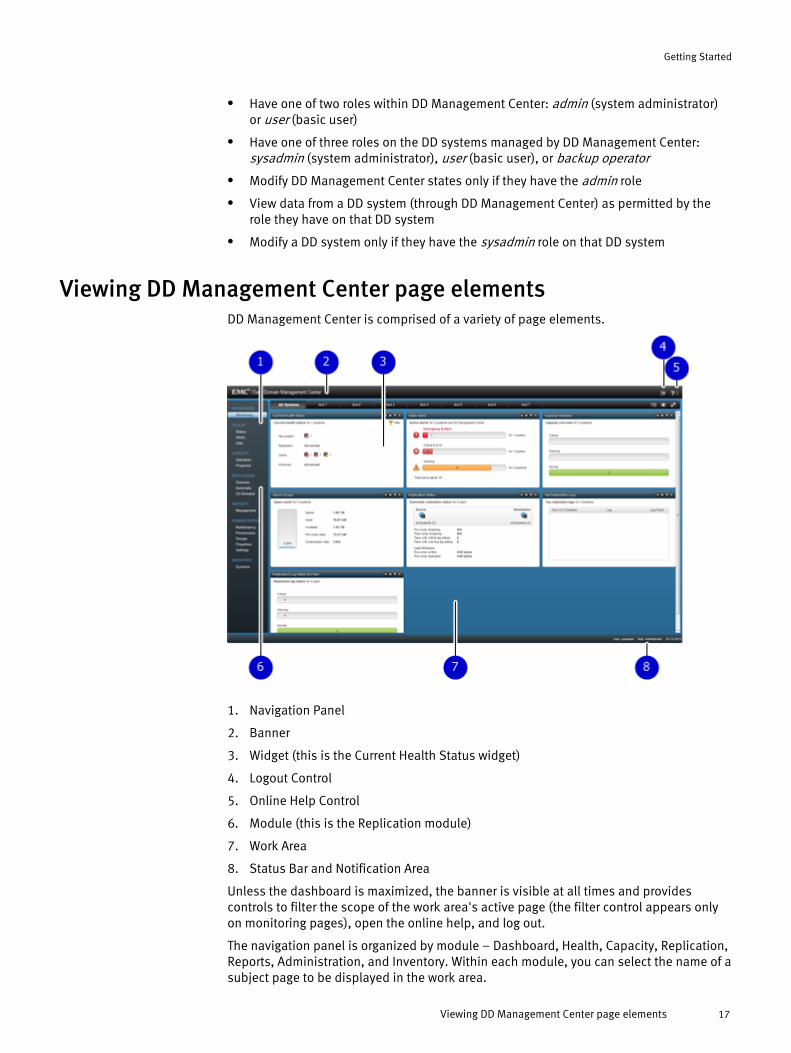
Viewing DD Management Center page elementsDD Management Center is comprised of a variety of page elements.
1. Navigation Panel
2. Banner
3. Widget (this is the Current Health Status widget)
4. Logout Control
5. Online Help Control
6. Module (this is the Replication module)
7. Work Area
8. Status Bar and Notification Area
Unless the dashboard is maximized, the banner is visible at all times and providescontrols to filter the scope of the work area's active page (the filter control appears onlyon monitoring pages), open the online help, and log out.
The navigation panel is organized by module – Dashboard, Health, Capacity, Replication,Reports, Administration, and Inventory. Within each module, you can select the name of asubject page to be displayed in the work area.
Getting Started
Viewing DD Management Center page elements 17

The status bar shows the active user name and role, date, and alerts notifications (whichyou can select, to see an informational pop-up with a link to the Alerts page).
Standard global controls (add, edit, delete) allow interaction with the application andmanage how information is displayed on pages with tables (sorting column content byascending/descending controls, hiding/displaying columns).
Navigating a DD Management Center pageNavigation elements on a DD Management Center page change the focus and scope ofthe content displayed in the work area.
1. Module topics are found on the left, in the navigation panel. The default view opensin the work area. In this picture, you have selected the Capacity > Utilization module.
2. Tabs (if applicable) are found at the top right, in the banner. In this picture, you canchoose from a System or MTree view.
3. Toggle buttons (if applicable) let you change from a standard DD system list, to agroup of systems, to a Tenant view, etc. If you choose groups, only groups that youhave created will be displayed. In this picture, you can choose from a Systems orGroups view.
Organizing the dashboardThe Dashboard holds widgets that you create from a set of monitoring functions. TheDashboard lets you quickly check important conditions, such as unreachable systems,active alerts, diminishing capacity, etc.
You can set up separate tabs on the dashboard and include specific widgets for each ofthose tabs. Suggested uses for tabs are to organize a set of systems based on groupmembership, location, OS version, data type, etc. Another suggestion is to organize bywidget type, for instance, a tab containing Current Health Status widgets for all systems.
Getting Started
18 EMC Data Domain Management Center 1.3 User Guide
By default, each user is assigned a Dashboard with one tab, populated by one each ofthe supplied widgets, configured to cover all of the systems that a user is monitoring. Youcan modify, add to, or even delete this default Dashboard tab.
A tab with all of its widgets can be copied to a new tab and then edited. Up to seven tabsare allowed.
Adding tabsTo customize your DD Management Center setup, you can add tabs – choosing a uniquename, number of columns, and placement.
Procedure
1. Select Dashboard > Monitoring.
2. On the dashboard, select the Add tab control in the banner, at the top right.
3. In the Add and Configure Dashboard Tabs dialog, select Add (green plus sign).
4. In the highlighted text field, enter the name for the tab.
5. Choose the number of columns for the tab (more columns produce smaller widgets).
6. Order the placement of the tab across the dashboard using the Move Up or MoveDown controls.
7. Select Save.
Results
The new tab is displayed on the dashboard.
Adding widgetsYou can also add widgets to customize your DD Management center setup.
Procedure
1. Select Dashboard > Monitoring.
2. On the dashboard, navigate to a tab (All Systems, etc.), or create a new tab (see thepreceding section).
3. Select the Add widget control in the banner, at the top right.
4. In the Add Dashboard Widget dialog, enter a Name that will reflect the widget's use.For example, using a Top Replication Lags template, you could name the widget “NewJersey Replication Lag” if you have set filters to show only those systems that replicateto New Jersey. The name must be unique for this tab.
5. Select a Template for the desired output. When you select a template, an icon appearsunder Example, showing an example of a widget of that type.
6. If applicable, in the Settings area, select any of the available options (such as filteringto narrow the scope of the widget monitoring). Widgets can be filtered using standardfilter primitives such as systems, groups, and properties. Also, depending on thetemplate, you may have other settings that you can configure.
7. Select Add.
Results
The new widget is displayed on the dashboard.
Widget templatesYou can add, edit, or delete widgets from the dashboard, by selecting the Add widgetcontrol in the banner at the top right, by using the Edit widget control in the banner of
Getting Started
Adding tabs 19

each widget, or by using the Remove widget control in the banner of each widget,respectively.
Current Health Status widget
The Current Health Status widget shows a summary of important health factors formonitored DD systems, such as any unmanaged systems, the status of the file system,replication status, alerts, and protocol status.
Selecting the Show detail control (>>) takes you to the Health > Status page.
Active Alerts widget
The Active Alerts widget shows the distribution of active alerts across all managedsystems by type – Emergency & Alert, Critical & Error, and Warning.
Color-coded bar graphs for severity levels show alert totals and the number of systemsaffected.
Selecting the Show detail control (>>) takes you to the Health > Alerts page, where acomplete list of Health Alerts is displayed.
Capacity Overview widget
The Capacity Overview widget shows the distribution of capacity usage across allmanaged systems.
Color-coded bars show critical, warning, and normal capacity levels.
A configuration option lets you show projected capacity usage for a selected period oftime (from 1 to 18 months).
Selecting the Show detail control (>>) takes you to the Capacity > Utilization page.
Space Usage widget
The Space Usage widget shows summaries of capacity factors – total space, space used,space available, pre-comp(ression) space used, and compression ratio.
It also displays alerts for systems at capacity and warnings for those nearing capacity.
Selecting the Show detail control (>>) takes you to the Capacity > Utilization page.
Replication Status widget
The Replication Status widget shows a summary of important status factors forreplication pairs.
This widget shows the number of replications being monitored, the number of source anddestination systems or groups, and data transfer totals. If any pairs have critical orwarning status, a warning icon displays, which when selected, opens the appropriateReplication page.
Configuration options include setting the widget to monitor only Automatic or only On-Demand replications. Additional options allow selecting specific replication statusfactors (such as pre-comp bytes written in the last 24 hours) for Automatic replications orfile transfer status for the last 24 hours when configuring On-Demand replications.
Selecting the Show detail control (>>) takes you to the Replication > Automatic page.
Getting Started
20 EMC Data Domain Management Center 1.3 User Guide

Note
For DD Boost (on-demand replication) monitoring, the DD system must be running DD OS5.3.1 or later. Any DD system running older software will not display DD Boost replicationpair associations between the source and destination systems on any of the filereplication reporting pages, widgets, or reports.
Top Replication Lags widget
The Top Replication Lags widget shows a list of systems exhibiting the longest lag time.
Selecting the Show detail control (>>) takes you to the Replication > Automatic page,where the complete list of filtered DD systems with lagging replications is shown, and youcan view or change the Lag Threshold Policy.
Selecting a row in the widget takes you to the Replication > Automatic page, filtered toshow only those pairs whose source is the selected system.
Note
For DD Boost (on-demand replication) monitoring, the DD system must be running DD OS5.3.1 or later. Any DD system running older software will not display DD Boost replicationpair associations between the source and destination systems on any of the filereplication reporting pages, widgets, or reports.
Replication Lag Status By Pairs widget
The Replication Lag Status By Pairs widget shows the count of replications with critical,warning, and normal levels, based on the Lag Threshold Policy.
Selecting the Show detail control (>>) takes you to the Replication > Automatic page,where the list of all filtered replications is shown, and you can view or change the LagThreshold Policy.
Note
For DD Boost (on-demand replication) monitoring, the DD system must be running DD OS5.3.1 or later. Any DD system running older software will not display DD Boost replicationpair associations between the source and destination systems on any of the filereplication reporting pages, widgets, or reports.
Copying tabsYou can create a new tab that contains the same widgets as an existing tab by copyingthat tab.
Procedure
1. Select Dashboard > Monitoring.
2. Select the Add tab control in the banner, at the top right.
3. In the Add and Configure Dashboard Tabs dialog, select the name of the tab to copyand then Copy.
4. In the text box, enter the new name for the tab (typing over “Copy of ...”).
5. If you want to change the number of columns, select the current number, and changeit using the drop-down list.
6. If you want to change the placement of the new tab, use the Move Up or Move Downarrows.
Getting Started
Copying tabs 21
7. Select Save.
Results
The new tab is displayed on the dashboard. You can open the widgets on the new tab tomodify their properties.
Modifying widgetsYou can modify widgets that were copied from a tab as a starting point for a new set; forexample, you could change the filter properties to monitor a different group, set ofsystems, or rule.
To modify a widget, use the Edit widget icon on the widget's title bar, and change thename, settings (if available), and filtering.
Note
You cannot change the widget type (as determined by the widget template) with the Editfunction.
Organizing managed DD systemsWhen you add DD systems to DD Management Center, the “Add systems” wizard includesoptions to assign each system to a group, or groups, and to set properties for it.
As you organize and catagorize each system, be aware that:
l Groups can be applied only to DD systems.
l Properties can be applied to DD systems, MTrees, and replication contexts.
l A default set of system properties (DD system model, DD OS version, domain name,and data center) is automatically assigned when a system is added, so you will needto set only custom properties. You can also modify (but not delete) data centerproperties, as needed.
After you have completed the initial setup for each DD system, you can continue to addand edit values for properties, and you can assign and reassign group membership.
Creating groupsGroups are ways to organize DD systems under a specific name, in a hierarchicalstructure created by the DD Management Center administrator.
Groups are helpful for performing searches. When used with filters, groups reduce thenumber of systems returned. Groups can contain other groups and/or DD systems. Agroup can belong to only one group, but a DD system can belong to many groups. Youstart by creating one or more super-groups at the Groups level, and then add sub-groupsand DD systems.
Note
DD systems cannot be added at the root Groups node. Group hierarchy structures cannotbe changed; they must be deleted and re-created to change the structure.
Procedure
1. Select Administration > Groups.
2. To add a group at the root level, select Add (green plus sign).
Getting Started
22 EMC Data Domain Management Center 1.3 User Guide

3. Make sure only the “/” is in the Path box. Enter a name for the new group, and selectSave.
The /newgroup is listed in the Groups panel.
4. To add a sub-group to a group, select a group (which will be the parent group) fromthe Groups panel, select Add (green plus sign), enter a name for the sub-group, andselect Save.
The sub-group is nested under the parent group in the Groups panel.
5. After a DD system has been added to DD Management Center, it can be added to agroup. Select the target group from the Groups panel, and select Add (green plussign). In the Add Group dialog, select a DD system from the Available Systems panel,select > to move the system into the Systems in the Group panel, and select Save.
The DD system is displayed in the Group group name Details panel when the group isselected in the Groups panel. When a DD system resides in more than one group, youcan hover the cursor on the Information control to display the group assignments.
Adding properties to systems, MTrees, replication pairsProperties provide information for classifying systems, and the data contained in MTreesand Replication contexts, for searching, filtering, and organizing. For example, you couldassign properties to help filter the list of DD systems in the Inventory > Systems page andnarrow the scope of output produced by a dashboard widget or generated report. When aDD system is added to DD Management Center, a set of default administration properties(DD system model, DD OS version, domain name, and data center) is automaticallyadded. You can add and assign other properties as needed.
Procedure
1. Select Administration > Properties.
2. At top right, select one of the tabs (System, MTree, or Replication), and select Add(green plus sign).
3. In the Add Property dialog, enter a name for the property, and select its operationtype:
l String – Allows a string of up to 256 characters to be set when assigning theproperty, for example, you could name the property “Comments”, and a user couldenter “Waiting for Tom's response”, “Not ready yet”, etc.
l Boolean – Creates a condition where you can assign one of two values, forexample, you could name the property “Restored?”, and possible values could be“True” or “False”, or “Yes” or “No”.
l Fixed-value String – Lets you provide a name and specific values for the property,for example, “Department” could be the name, and “Finance”, “HumanResources”, “Marketing”, etc., could be the values. Selecting the option Allowmultiple types lets you assign more than one value.
4. Select Add.
5. Assign values to the properties, as described in “Assigning Properties”.
Getting Started
Adding properties to systems, MTrees, replication pairs 23

Adding (registering) DD systems to DD Management CenterBefore you can manage a DD system in DD Management Center, you must add (register) itto the inventory. A maximum of 100 DD systems can be added to a DD ManagementCenter. Groups of up to 20 systems can be registered at one time.
Procedure
1. Select Inventory > Systems.
2. Select Add (green plus sign). Enter the following for the first DD system, then selectAdd to continue adding systems (up to 20 systems total). Make sure the box next tothe system being added is checked. Select Register to continue:
l Host name (required) – Enter the fully-qualified host name (use alphanumericcharacters, dashes, periods, and underscores) or IP address. Ensure that the hostname and the DNS name for the DD system match; a mismatch may causeproblems with backup software.
l Sysadmin Password (required) – Enter the sysadmin password used on the DDsystem (required).
l Firewalls (optional) – Enter the inbound and outbound proxy host name (or IPaddress) and port number to be used by the firewall. If this option is selected, andyou do not change the port number, the default (3009) is used. If you do change it,the port number must be between 1 and 65535. The default port settings let DDManagement Center communicate with the DD system. If the ports have beenchanged on the firewall or the DD system, they should also be updated here.
Note
For more detailed information, see the next section, Inbound and outbound proxyhost names and port numbers used by the firewall on page 25.
l Certificate (optional) – Check certificate information by clicking in the associatedcells. The Subject name in the DD Management Center CA certificate should matchthe DD Management Center host name, or SSL will fail the host verification.
3. The status page reports the success and/or failure of the additions. In the event of anerror, select Back to return to the first page to display error messages and correcterrors, or to delete the system. When you have fixed all of the errors, select Next tocontinue to the Properties page or Close to quit. (The Next button will be disableduntil all of the errors are corrected.)
Note
Any settings made on the Properties page, the Groups page, and the Thresholds pagewill be applied to all of the systems being added.
4. Optionally, on the Properties page, select checkboxes from the available propertieslist to assign properties to the DD systems, and select Next to continue to the Groupspage.
5. Optionally, on the Groups page, select checkboxes from the available groups list tomake all DD systems members of the selected groups, and select Next to continue tothe Thresholds page.
6. Optionally, on the Thresholds page, set warning and critical capacity thresholds forthe DD systems (shown on capacity views and in reports).
Getting Started
24 EMC Data Domain Management Center 1.3 User Guide

7. Select Finish.
Results
A progress bar appears on the page showing the progress of the initial datasynchronization for the newly added DD system(s). Additionally, job progress details canbe tracked on the Health > Jobs page.
After a DD system is added to DD Management Center, all historical information for thatDD system is copied to DD Management Center. From that point on, whenever operationaldata changes on that DD system, the DD system notifies DD Management Center, whichimmediately polls the DD system to receive that new information.
Common Causes of Errors While Adding SystemsThe following checklist may help you resolve some errors that can occur when trying toadd a DD system to DD Management Center:
l Make sure the DD system is online. A DD system must be online in order to be addedto DD Management Center.
l If you specified a port number in the proxy firewall settings, make sure it is correct.
l Make sure you have added the DD Management Center to the DD system as a host.
l Make sure there are no networking issues preventing communication between the DDManagement Center and the DD system.
l If you specified a host name for the DD system, make sure the host name can beresolved in your name space (DNS).
l Make sure the password entered for the system is correct.
l Make sure the DD OS version of the DD system is supported by your current version ofDD Management Center (see the EMC Data Domain Management Center Version SupportMatrix).
l Make sure the DD system is not already managed by another DD Management Center.To resolve this, you can either delete the system from the original DD ManagementCenter or select the Override adding systems checkbox. The system will be added tothe new DD Management Center, but the system’s status will be changed tounmanaged on the original DD Management Center, and data collection will besuspended for that system.
Inbound and outbound proxy host names and port numbers used by the firewallFirewalls provide an additional level of security when transmitting data between DDManagement Center and DD systems. You must set inbound and outbound proxy hostnames (or IP addresses) and port numbers for a firewall if the connection between DDManagement Center and the DD system is through a proxy.
The terms inbound and outbound are from the perspective of DD Management Center, soinbound means from the DD system to DD Management Center, and outbound meansfrom DD Management Center to the DD system.
Starting with the simplest situation (direct connection) for explanation, here are somescenarios and how you would set up the inbound and outbound proxy firewall hostnames (or IP addresses) and port numbers.
DD Management Center connecting directly to a DD system (simple case)In the simplest case of connecting DD Management Center to a DD system, the DD systemis able to resolve "ddmc.myco.com" to 1.1.1.1, and DD Management Center is able toresolve "ddr.myco.com" to 1.1.1.2.
Getting Started
Inbound and outbound proxy host names and port numbers used by the firewall 25

Figure 1 Simple case: DD Management Center connecting directly to a DD system
In this simplest case, it is assumed that:
l DD Management Center is able to connect to the DD system using TCP.
l The DD system is similarly able to connect to DD Management Center using TCP.
l DD Management Center, by default, tries to translate the host name of a DD system(that is, the name that is returned using net show hostname or the name that yousee in the DD System Manager) to an IP address using DNS or a host file.
l The DD system similarly tries to translate the DD Management Center host name to anIP address using DNS or a host file.
l Both DD Management Center and DD OS (on the DD system) try to connect to port3009 on the remote system.
DD system with multiple network interfacesWhen a DD system has multiple network interfaces, you need control of the specificinterface used by DD Management Center.
Figure 2 DD system with multiple network interfaces
In this case, the DD system host name probably does not translate to the IP address ofthe desired network interface. To direct DD Management Center to the desired interface,you must set the outbound proxy host name (or IP address) to a DNS name or the IPaddress of the desired interface. It is not necessary to set the inbound proxy host nameor port number.
NAT firewall between DD Management Center and DD systemWhen a NAT (network address translation) firewall exists between DD ManagementCenter and a DD system, the firewall is configured so that when you connect to a port onthe firewall, the firewall proxies that connection to an IP address and port number on thedestination system. The IP address to which DD Management Center connects does notmatch any IP address on the DD system, itself. Port numbers may be re-mapped, as well.Therefore, to connect to a DD system, you would connect to a port other than 3009 on theproxy.
Getting Started
26 EMC Data Domain Management Center 1.3 User Guide
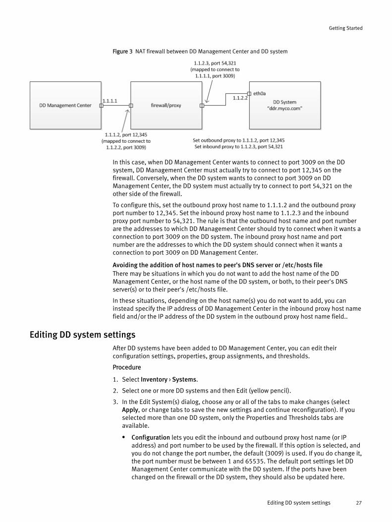
Figure 3 NAT firewall between DD Management Center and DD system
In this case, when DD Management Center wants to connect to port 3009 on the DDsystem, DD Management Center must actually try to connect to port 12,345 on thefirewall. Conversely, when the DD system wants to connect to port 3009 on DDManagement Center, the DD system must actually try to connect to port 54,321 on theother side of the firewall.
To configure this, set the outbound proxy host name to 1.1.1.2 and the outbound proxyport number to 12,345. Set the inbound proxy host name to 1.1.2.3 and the inboundproxy port number to 54,321. The rule is that the outbound host name and port numberare the addresses to which DD Management Center should try to connect when it wants aconnection to port 3009 on the DD system. The inbound proxy host name and portnumber are the addresses to which the DD system should connect when it wants aconnection to port 3009 on DD Management Center.
Avoiding the addition of host names to peer's DNS server or /etc/hosts fileThere may be situations in which you do not want to add the host name of the DDManagement Center, or the host name of the DD system, or both, to their peer's DNSserver(s) or to their peer's /etc/hosts file.
In these situations, depending on the host name(s) you do not want to add, you caninstead specify the IP address of DD Management Center in the inbound proxy host namefield and/or the IP address of the DD system in the outbound proxy host name field..
Editing DD system settingsAfter DD systems have been added to DD Management Center, you can edit theirconfiguration settings, properties, group assignments, and thresholds.
Procedure
1. Select Inventory > Systems.
2. Select one or more DD systems and then Edit (yellow pencil).
3. In the Edit System(s) dialog, choose any or all of the tabs to make changes (selectApply, or change tabs to save the new settings and continue reconfiguration). If youselected more than one DD system, only the Properties and Thresholds tabs areavailable.
l Configuration lets you edit the inbound and outbound proxy host name (or IPaddress) and port number to be used by the firewall. If this option is selected, andyou do not change the port number, the default (3009) is used. If you do change it,the port number must be between 1 and 65535. The default port settings let DDManagement Center communicate with the DD system. If the ports have beenchanged on the firewall or the DD system, they should also be updated here.
Getting Started
Editing DD system settings 27

Note
For more detailed information, see the previous section, Inbound and outboundproxy host names and port numbers used by the firewall on page 25.
l Properties lets you edit information for classifying systems, and the datacontained in MTrees and Replication contexts, for searching, filtering, andorganizing. If you selected more than one system, and there are different values forthat property on the different systems, the field will show Mixed values. If youchange the value, all systems will receive the new value. There are default anduser-created (Administration > Properties > System) properties. The defaultproperties of Model, OS, and Domain Name are not editable. Data Center is a“hybrid” fixed-value string-type property. Because it is a default system property, itcannot be deleted, but its values can be edited and set for a DD system.
l Groups let you organize DD systems under a specific name, in a hierarchicalstructure created by the DD Management Center administrator, which is helpful forsearches. You can add or remove group assignments, and select or deselect groupassignments for the system. Any number of groups and subgroups can beselected.
l Thresholds indicate the warning and critical capacity thresholds for DD systemsand are shown on capacity views and in reports. Use the slider to specifythresholds as a percentage of total capacity. When editing multiple systems withmixed warning thresholds, the initial warning value is zero. When editing multiplesystems with mixed critical thresholds, the initial critical value is 100. If youchange the value, all systems will receive the new value.
4. Select OK to save and exit system reconfiguration.
Assigning propertiesThe procedure to assign a property varies, depending on where the property is used: DDsystems, replication, or MTrees.
Assigning system property valuesAfter you add a property to a DD system (Administration > Properties > System), you canassign values to that property.
Procedure
1. Select Inventory > Systems.
2. Select one or more systems.
3. Select Edit (yellow pencil), and in the Edit System dialog, select the Properties tab.
4. For each property listed, assign a value. If you selected more than one system, andthe systems have different values for that property, the field will show Mixed values. Ifyou change the value, all systems will receive the new value. An Undo control isprovided for undoing the setting, and a More Details control shows the saved valuesfor each selected system. For properties that were created as a:
l string – Enter the text that will be displayed as the value.
l boolean – Select one of the two values from the drop-down list.
l fixed-value string (and multi-value) – Select the value from the drop-down list.
5. Select OK to set the values.
Getting Started
28 EMC Data Domain Management Center 1.3 User Guide
Assigning replication property valuesAfter you add a replication pairs property (Administration > Properties > Replication), youcan assign values to that property.
Procedure
1. Select Replication > Overview or Replication > Automatic.
2. Select a replication pair.
3. Select Assign Properties and set a value. For properties that were created as a:
l string – Enter the text that will be displayed as the value.
l boolean – Select one of the two values from the drop-down list.
l fixed value string (and multi-value) – Select the value from the drop-down list.
4. Select Assign to set the values.
5. To see values assigned to replication contexts, you can add this property as a columnin the replication table on the Automatic replications page:
a. Select the Show Columns icon.
b. Select the checkbox of the property from the list.
c. You will see the name of the property as the column title, and any value assignedto a context will appear in the cell.
Assigning MTree property valuesAfter you add an MTree property (Administration > Properties > MTree), you can assignvalues to that property.
Procedure
1. Select Capacity > Utilization > MTree tab.
2. At bottom right, in Properties, select Assign and set a value. For properties that werecreated as a:
l string – Enter the text that will be displayed as the value.
l boolean – Select one of the two values from the drop-down list.
l fixed value string (and multi-value) – Select the value from the drop-down list.
3. Select Assign to set the value.
Displaying property informationAssigned property values can be displayed either by selecting an element (such as a DDsystem) and displaying all of the properties assigned to it, or by selecting a property anddisplaying all of the elements to which it is assigned.
Displaying properties for an elementHow you display properties for an element depends on the type of element: DD systems,replication pairs, or MTrees.
Procedure
l Systems – Select Inventory > Systems, and select a DD system.
All properties assigned to that system are displayed in the Properties panel.
Getting Started
Assigning replication property values 29
Note
You can also display properties by selecting the “gear” control in the systems banner.When you select one or more properties from the list of configured properties, acolumn for that property is added to the table. To hide the property, uncheck theproperty from the list. Some properties may not be removed from the table, so theywill not appear in the list of configured properties under the gear control.
l Replication – Select Replication > Overview, select a replication pair, and select PairDetails.
Any properties assigned to the replication pair are displayed in the Properties panel.
l MTree – Select Capacity > Utilization, select the MTree tab, and select an MTree.
Any properties assigned to the MTree are displayed in the Properties panel.
Finding elements by property valueYou can also find elements by looking at all of the assigned property values.
Procedure
1. Select Administration > Properties, and select the property type (System, MTree, orReplication).
The table shows all of the properties that have been created. Selecting a propertydisplays its assigned values in the panel at the right.
2. To display where the property is assigned, select a property, and select the icon onthe right side of the Key column.
In the Property Assignment dialog, you can see the property type, the element where itis assigned, and the property values.
Managing groupsAlthough group creation and modification can be performed only by the DD ManagementCenter system administrator, any user can apply group designations to their DD systemsand can see the complete group structure, although RBAC (role-based access control)permissions control the systems that are displayed for each user.
Any permissions that are applied to a group affect all DD systems in that group. A lockimage is added to the groups folder icon when permissions are directly applied to thatgroup.
Use the Administration > Groups page to perform group management:
l Use Add to create groups or to add DD systems to existing groups.
l Use Delete to remove DD systems from the group-level organization. (You cannot usedelete to remove systems from a group. But you can edit the group, and removesystems by selecting them in the right panel and selecting the left-pointing arrow)
l Use Edit on a selected group to modify the presence of DD systems within that groupor the name of the group.
Note
Groups cannot be dragged and dropped into a different location; they must bechanged with the Edit function.
Getting Started
30 EMC Data Domain Management Center 1.3 User Guide

Managing replication lag threshold policiesReplication lag threshold policies warn you when replication pairs do not completereplication within a set amount of time.
By assigning a replication lag threshold policy, you are assured that notifications will bedisplayed in the Replication > Automatic page and the Top Replication Lags andReplication Lag Status widgets when the replication has not completed within the timeperiods you have set for Warning and Critical levels.
The default policy level for Warning is 24 hours, and the default for Critical is 48 hours.
Replication lag threshold policies can be created only for MTree, collection, and directoryreplication. Lag threshold policies for On-Demand replications are not supported.
Procedure
1. Select Replication > Automatic.
2. Select one or more replication pairs from the table.
3. To create a policy, select Lag Threshold Policy (or right-click the pair, and select theoption).
a. In the Lag Threshold Policy dialog, from the Threshold policy menu, select Create anew policy.
b. In the Manage Lag Threshold Policies dialog, select Add.
c. In the text box, enter the policy name, and use the slider controls to set thethreshold points for the Warning and Critical lag levels.
d. Select Save.
4. Back in the Lag Threshold Policy dialog, select a policy from the Threshold Policymenu, and select Assign.
Results
The policy is applied to the selected replication(s). The assigned policy name is displayedin the table in the Threshold Policy column.To modify or destroy a policy, select Manage Lag Threshold Policies (or right-click thepair and select the option). In the Manage Lag Threshold Policies dialog, select a policyfrom the list, and select Edit or Delete. If a deleted policy was assigned anywhere, it isreplaced with the Default policy. Select Save to exit.
Note
The Default policy cannot be renamed or deleted, but it can be modified.
Working with filtersFilters are used to selectively define the output of a DD Management Center function. Forexample, filters can be used to define the scope of elements that display on a page, tailorthe output of a report, or target the DD systems to be monitored for Dashboard widgets.The Filter (funnel-shaped) control appears on pages and dialogs whenever a filter can beused.
The drop-down menu on the Filter control allows you to select the groups, properties, DDsystems, or rules to be used for filtering. When a filter is active on a page, the Filtercontrol is highlighted in yellow. Filtering can be switched on or off using the Filter controlas a toggle.
Getting Started
Managing replication lag threshold policies 31

The Filter by rule option lets you create custom rules that can be saved for reuse or run inthe current location. The rule can be built using any of the standard filter criteria (groups,properties, DD systems), along with any existing properties or groups that have beencreated. Controls for logic (is, is not, contains, does not contain, etc.) are provided, andstatements can be inclusive or selective.
To create a custom filter rule:
Procedure
1. From the Filter drop-down menu, select Filter by rule.
2. In the Filter by Rule dialog, provide a name for the filter.
3. Using the selection menus in the Match the following area, create the criteria for yourrule. The criteria consists of one or more statements.
Create the first statement by selecting an object from the first menu (System, Group,Model, OS, Domain Name, etc.) and a logic condition (contains, does not contain, is,is not, etc.), then the target (text you input or a menu selection, based on the previousselections). For example, a statement could be “Model is DD880”.
4. If needed, add more statements with the Add row (+) control, or add conditions to therule using the Block (...) control, which adds the choice of All or Any to the Match thefollowing area), and create additional statements.
5. Select the Save (disk) control to make this filter available from the Filter menu list orselect Filter to run the filter once and exit.
6. To remove the filter and return to unfiltered content, select Clear filter from the Filtermenu.
Note that the filter may still be available with the Recent filters option on the Filtercontrol list.
Getting Started
32 EMC Data Domain Management Center 1.3 User Guide

CHAPTER 3
Monitoring Data Domain Systems
l How DD Management Center helps you monitor DD systems................................. 34l Data retention policy for DD Management Center...................................................34l Space projection algorithm for DD Management Center......................................... 35l Performing daily monitoring.................................................................................. 35l Monitoring capacity...............................................................................................40l Checking the System Details lightbox....................................................................42l Monitoring replication........................................................................................... 43l Monitoring status with reports...............................................................................47
Monitoring Data Domain Systems 33

How DD Management Center helps you monitor DD systemsThe monitoring tools of DD Management Center let you examine a wide array ofoperational information about managed DD systems.
After a DD system is added to DD Management Center, all historical information for thatsystem is copied to DD Management Center.
When operational data changes on a DD system, the DD system notifies DD ManagementCenter, which immediately polls the DD system to get the latest operational data.
DD Management Center monitoring tools draw on this data for current and historicalreporting and for creating trend projections.
DD Management Center monitoring tools are highly visual – using charts, graphs, andcolor coding to help you interpret essential data points and easily notice alerts for criticalmarkers.
DD Management Center monitoring tools help you focus on areas of interest. They canshow mile-high status checks of all managed DD systems and check a specific group ofDD systems, as well as drill-down to check the health or operational history of a singlesystem’s components. For capacity monitoring, you can easily check current operationand historical data and perform capacity predictions based on usage trends.
Using the filtering and grouping options provided on monitoring pages, DD ManagementCenter lets you easily shape your data presentation so you can focus on viewing just theinformation you need.
In addition to data provided on the interface, you can generate reports to compileoperational data that can be exported. Reports can be generated ad hoc or scheduledand emailed to a list of interested parties.
Data retention policy for DD Management CenterDD Management Center maintains up to ten years of performance and capacitymeasurements for the DD systems it is monitoring. Data from the DD systems areconsolidated into hourly sample points, generally collected at 30 minutes past the hour.The hourly samples are consolidated into daily samples, where a day is considered to runfrom Noon to Noon. Daily samples are further consolidated into weekly samples, where aweek begins on Sunday.
To reduce the amount of space needed to store this historical data, DD ManagementCenter periodically discards older samples. The number of samples retained depends onthe nature of the data and whether the sample is hourly, daily, or weekly data. Thefollowing table shows the length of time that DD Management Center retains eachsample.
Table 1 Data retention policy for DD Management Center
type of data keep hourlysamples for
keep dailysamples for
keep weeklysamples for
Collection space usage 3 months 1 year 10 years
MTree space used 1 month 3 months 10 years
Automatic replication (bytestransferred and lag)
1 month 3 months 10 years
Monitoring Data Domain Systems
34 EMC Data Domain Management Center 1.3 User Guide

Table 1 Data retention policy for DD Management Center (continued)
type of data keep hourlysamples for
keep dailysamples for
keep weeklysamples for
On-demand replication (number offiles and bytes transferred)
3 months 1 year 10 years
Performance (CPU and network) 1 month 1 year none created orretained
Finally, DD Management Center retains up to 2,000 historical alerts from each DD systembeing monitored.
Space projection algorithm for DD Management CenterDD Management Center uses a sophisticated algorithm to project growth in space usageand to predict when a DD system will run out of space. This algorithm was developed andverified using years of autosupport reports and should be quite accurate.
For this algorithm, DD Management Center uses a seven-day moving average instead ofactual measured values. This smooths out the effects of file system cleaning and otheractivities that repeat every week (for example, deleting an old full backup and creating anew one every weekend).
The goal of this algorithm is to compute a linear projection of space growth using anoptimal set of recent data points. The data history is scanned to find the projection withthe best fit, that is, the regression with the highest R2 value.
The R2 value is a measure of how close the regression fits the actual measurements. Avalue of 1 means the fit was perfect. A value of 0 means there was no fit at all. A value of0.8 means that DD Management Center found a projection that matches themeasurements closely enough to be meaningful and not misleading.
After the best fit is determined, the projection must pass the following validation tests toensure that the prediction is accurate:
1. DD Management Center must have at least 15 days of historical data.
2. The regression R2 value must be at least 0.8 or higher.
3. The slope of the regression must be positive (that is, space usage is growing, notshrinking).
4. Time-to-full must be less than 10 years in the future.
5. The DD system must be at least 10% full.
6. The most recent data sample must be within 5% of the projection.
Combining all of these validation criteria accounts for typical DD system usage behavior,such as space becoming free after a cleaning cycle, jumps in usage as new backup loadsare stored on the DD system, and space becoming free when backups are deleted.
Performing daily monitoringUsing DD Management Center to perform daily monitoring of your site lets you check forunusual activity before it becomes a serious problem.
You should perform the following tasks at least daily to get an overview of the operationalstatus of your DD systems and data replication.
Monitoring Data Domain Systems
Space projection algorithm for DD Management Center 35
Checking dashboard status widgetsThe Dashboard > Monitoring widgets (Current Health Status, Active Alerts, CapacityOverview, Space Usage, Replication Status, Top Replication Lags, and Replication LagStatus By Pairs) provide an overview of key performance indicators for your monitored DDsystems.
You can set up from one to seven tabs to hold any combination of these widgets. Bydefault, one tab is provided named All Systems that is populated with one of each type ofwidget.
The graphs, dials, and color-coded alerts make it easy to spot system operationalproblems. Many components on the widgets provide a link to a full-featured page for thefunction so you can drill-down to see complete information.
If any of its monitored systems are not online, a Status button appears at the top rightcorner of a widget (except for Active Alerts). Selecting this button shows the count ofsystems with connection issues. Selecting the Show Health Status link opens the Health> Status page, where a list of these systems is displayed.
Widget templates for commonly used monitoring functions can be used to create widgetsfor all managed systems or filtered by a set of criteria such as groups, properties,systems, or rules.
After they have been created, you can drag widgets around the dashboard to improvetheir organization. A widget or a tab with several widgets can be copied and modified tocreate additional widgets.
The size of the dashboard can be toggled between full screen and normal view.
Checking system capacityThe system capacity widgets help you to spot shortfalls in overall managed storagecapacity and monitor managed system storage usage.
CapacityThe Capacity widget displays systems that are nearing warning or critical storage capacitylevels.
Also, if configured, you can monitor the projected capacity usage for an upcomingselected interval.
Space UsageThe Space Usage widget lets you monitor aggregate totals of storage levels for all of theDD systems it is configured to manage. This widget monitors the total storage capacity ofall systems (for space that is used and available) or a selected group if a filter is set.
You can also check pre-compressed space usage and compression ratios to verify thatdeduplication is working as expected.
Checking replication progressThe replication widgets provide replication status, problems, and statistics.
Replication StatusThe Replication Status widget highlights replications with performance problems for thewidget’s monitored systems. Also, if configured, it shows the total bytes written and thetotal bytes replicated in the last 24 hours.
Top Replication LagsThe Top Replication Lags widget shows source DD systems with replication pairsexhibiting critical and warning lag, ranked by severity (Critical, followed by Warning) and
Monitoring Data Domain Systems
36 EMC Data Domain Management Center 1.3 User Guide
by longest delay. The lag time for the worst performing replication pair on the system isshown, along with the lag trend for that pair (increasing, decreasing, or holding steady).Select a system entry to open the Replication > Automatic page, showing all pairsoriginating from that system.
Replication Lag Status by PairsThe Replication Lag Status by Pairs widget shows the count of replication pairs exhibitingCritical, Warning, and Normal threshold levels, based on the assigned policies. Selectinga bar takes you to the Replication > Automatic page, showing all pairs with that severity.
Checking health and alertsThe Dashboard health status and alerts widgets highlight systems that are reportingmajor reachability or operational problems. And if there are problems, the widgetsprovide drill-down links to system details.
Current Health StatusThe Current Health Status widget highlights unreachable systems and systems havingproblems with file system and replication operation, alerts, and data transmissionprotocols. The widgets show All Normal or show a count of systems exhibiting problems.
l Selecting the system count for each category navigates to the Health Status page,filtered to display the status of only that widget’s systems.
l Selecting the banner for unreachable systems navigates to the Health Status page toshow the status of just the unreachable systems.
l The marker for All Normal status has no navigation or drill-down behavior.
Active AlertsThe Active Alerts widget displays a tally of systems with outstanding alerts for Emergency& Alert, Critical & Error, and Warning, using color-coded bar graphs.
l The length of the bar shows the total number of alerts, while color and symbolprovide visual clues.
l Selecting the alert bar takes you to the Alerts page, filtered by the widget’s configuredfilters and the type of alert category.
Checking alert notificationsFor new, unacknowledged alerts on systems you are authorized to manage, always checkthe “Notification Area,” located in the lower left of the Status Bar (the bottom border ofthe DD Management Center window).
This Notification Area is not constrained by filter settings that are active, that is, itdisplays notifications of alerts for all of the systems you are authorized to manage.
The “New Alerts” area shows the current unacknowledged Emergency, Error, and Warninglevel alerts. Click anywhere in the New Alerts area to display a pop-up reporting theseverity, system name, and class of the new alert. After the pop-up has been displayed,the alerts notification is removed from the Alerts Notification area.
To see the alert details, select the “Show me these alerts” link to open the Health > Alertspage, where the table is filtered to show only the new alerts.
Checking health statusThe Health > Status page displays information about potential operational problems,such as connection status, replication status, alerts, etc.
The Systems/Groups/Tenants icons at the top right let you show all DD systems, or DDsystems organized by group or Tenant assignment.
Monitoring Data Domain Systems
Checking alert notifications 37

Note
Secure Multitenancy functionality requires DD systems running DD OS 5.5 or later.
LED colors indicate:
l Red – error or problem
l Yellow – error or warning
l Green – normal operation
l Grey – disabled components
l Grey “Empty Socket” – non-licensed components
Note
If a system is unreachable – but not disabled or non-licensed – the last known state ofthe LED is displayed.
For all three views:
l Hover the cursor over a grey LED in the Replication column to get a link to theReplication Overview, showing the pairs related to this DD system or Tenant Unit.
l Hover the cursor over a red LED in the Alerts column to get a link to open the Alertspage.
l Use the Sort Ascending option for the Connection Status column to find connectionproblems on systems.
l If the File System is destroyed or disabled, a red LED is displayed. As a result of thisnon-activity, Protocols and Replication are affected and display a red LED as well.
For the Systems or Groups views:
l Hover the cursor over an "empty socket" LED in the VTL column to get a link to launchDD System Manager.
l The System Details control (top left) launches the System Details Lightbox for theselected DD system.
For the Tenants view:
l When a DD system is offline, the Tenant Units in that system become offline as well,and the Tenant Unit offline icon is displayed in the Tenant Unit tree.
l Unmanaged Tenant Units, as well as MTrees and Storage Units that do not belong toa Tenant Unit, are not displayed.
l Only Tenants and Tenant Units that belong to the current user are displayed.
l The Tenant Unit Details control (top left) launches the Tenant Unit Details Lightbox forthe selected Tenant Unit.
Checking health alertsIn addition to checking Health Status for operational problems, also check the Health >Alerts page. Be sure to watch for new or repeating alerts.
Use the Systems/Tenants icons at the top right of the page to toggle page content toshow all DD systems or DD systems organized by tenant assignment.
When you select the Tenants icon, note the following:
l The Tenant Unit Details control (top left) launches the Tenant Unit Details Lightbox.
Monitoring Data Domain Systems
38 EMC Data Domain Management Center 1.3 User Guide
l A special “all” Tenant Unit alert is applied to all Tenant Units in the system.
Note
Secure Multitenancy functionality requires DD systems running DD OS 5.5 or later.
The page banner provides summaries of the total number of alerts: those that are errorsand above, and those that are warnings.
At the top right, you can select the Active Alerts or All Alerts tab, depending on what youneed to view. Many, but not all, alerts remain active until manually cleared.
The Date range filters (Last 12 hours, Last 24 hours, Last 7 days, Last 30 days, All activealerts, and Custom). let you narrow or expand the focus of alert scoping or go back to aspecific point in time.
The column controls sort the alert list by Severity, System Name, Post Time, Class,Message, and Object ID. The System Name column includes a filter for entering systemname text.
Selecting an alert in the table shows descriptive information about the alert in the Detailsand the History panels, at the bottom of the page. To see a summary of the alert's history,select the More Details link to see a list of every occurrence of the alert at the site.
To investigate or resolve an alert on a DD system, open the DD System Manager bydouble-clicking the alert in the table, or use the Launch DD System Manager control,which is enabled when a DD system alert is selected.
Note
For additional information on specific alerts, see the Error Message Catalog on the EMCOnline Support Site.
Checking health jobsIn addition to checking Health Status for operational problems, also check the Health >Jobs page. This page displays information about jobs (also called tasks) that have beeninitiated from DD Management Center, including jobs still in progress and jobs that havecompleted, whether successfully or not. Details of a task, including its subtask status,are shown for a selected task in the Details panel.
You can filter jobs by Failed, In progress, and/or Succeeded.
You can select a job from the main list and expand the steps to see sub-steps up to tenlevels deep.
When upgrading one or more DD systems, the progress of a selected In-progress task canbe paused and resumed with the Status control.
Tasks can run on the DD Management Center alone or can run on the DD ManagementCenter and a DD system. For example, the Report Generation task runs solely on DDManagement Center; other tasks, like Upgrade, run mostly on the DD system, but askeleton process on DD Management Center keeps track of the task's progress. And stillother tasks run mostly on DD Management Center (such as Adding Systems), but havesubtasks that run on the DD system. Tasks that run on DD System Manager (native to theDD system) are not shown in the Jobs list – only those tasks initiated from DDManagement Center are shown.
The displayed list of tasks is dependent on the role:
l A person with a user role on a DD system or DD Management Center sees only thetasks they initiated on that DD system or DD Management Center.
Monitoring Data Domain Systems
Checking health jobs 39

l An admin on a DD system or DD Management Center sees all jobs on that DD systemand DD Management Center.
Monitoring capacityThe Capacity pages display information about storage utilization, allowing you to togglebetween managed DD systems and MTrees. You can check current and historical spaceconsumption, as well as estimate projected near-term future storage needs.
Checking system capacity and disk space usageThe Capacity > Utilization page displays storage usage amounts for monitored DDsystems (default) or their MTrees. You can also observe disk space usage trends.
The System/MTree tabs at the top right let you choose how to display data. Then, afterchoosing System, there are icons (just underneath) to let you select Systems or Groups.With MTree, you can select Systems or Tenants.
In the MTree Tenants view:
l You can enter a list of comma-separated strings to filter the Tenant Unit column.
l You can also sort MTrees within a Tenant Unit.
l In the Space Usage section:
n When a Tenant Unit is selected, the information is aggregated based on all MTreeswithin that Tenant Unit.
n When a Tenant is selected, the information is aggregated based on all MTreeswithin all Tenant Units pertaining to that Tenant.
The last row shows aggregated totals. Selecting multiple systems displays theiraggregated totals.
Using this data, you can:
l Monitor the capacity of logically grouped or single systems to track usage andidentify systems that are using capacity too quickly
l Identify systems that have used all their storage space
l Identify systems that have deviated from their norm for compression ratio, etc.
l Identify systems as targets for new back ups, replication, and migration
l View the amount of data written during a particular timeframe, such as a back-upcycle, and determine how much it has been compressed
l Identify when garbage collection runs and how much space is reclaimed
l For Extended Retention-enabled systems, identify how much space is available andused on the Archive and Active tiers, and how well it is compressed
Selecting a System displays the Space Usage and Charts areas, at the bottom. ForMTrees, there is also a Properties area.
In theSpace Usage area, when a System is selected, space usage amounts are shown forthe current time and the last 24 hours, pre-comp used, and configurable columnsshowing Compression Factor, Cleanable, and Capacity Thresholds for Warning and/orCritical states (by default, thresholds are set to 80% for warning and 90% for critical; theycan also be set from the Inventory > Systems page Edit control). The Warning and CriticalCapacity Thresholds columns can be sorted by ascending/descending controls and canalso filtered by an entered value (greater, lesser, or equal to entered value).
Monitoring Data Domain Systems
40 EMC Data Domain Management Center 1.3 User Guide
Note
The Space Usage amounts may not exactly match capacity totals reported by DD SystemManager. Because of the polling delay of up to an hour, DD Management Center reportingwill always lag. This is especially true if there is a lot of churn on the monitored system;the discrepancy will be more visible, and there is a possibility that DD ManagementCenter may never catch up with DD System Manager capacity totals.
In the Charts area, the Space Usage, Consumption, and Data Written tabs provideinformation about:
l Systems that are consuming space at a rate significantly greater or less than theirhistorical norm
l Total capacity, amount consumed, and compression ratio (aggregate) for a group ofsystems
l Data ingest rate for a group of systems, for example, the total data ingest rate for thelast 24 hours
l Systems that are out of space or critically low on space
l The amount of data that was backed up the previous night (24 hour period), and thecompression ratio for a group of systems
l The last time that garbage collection was run and how much space was reclaimed
Note
This guide assumes you are familiar with capacity terms, as introduced in the EMC DataDomain Operating System Administration Guide. See that guide, or the DD System Manageronline help, for explanations of these terms.
Checking projected system capacityThe Capacity > Projected page helps you plan future capacity needs.
You can use this information to:
l Predict when systems will run out of storage space or reach a critically low point
l Determine future capacity needs by projecting historical and current trends
l Determine targets for migration by projecting the systems that are filling up, versusthe same model systems that will have space available
Each entry in the table shows the system name, model, OS version, and a connectionstatus icon with a pop-up containing a link to the Health > Alerts page. The space usageamounts (size, used, and free) for current, selected past, and projected months areprovided. A storage graphic depicts the system's capacity by percentage used, with colorcoding to show normal, warning, and critical threshold levels.
You can select the timeline to choose a specific month (past or future), which creates adate column for comparison analysis. Projections are based on historical data andrequire at least 15 daily data points to work.
If insufficient data prevents an accurate projection, informational messages aredisplayed.
Monitoring Data Domain Systems
Checking projected system capacity 41

Table 2 Insufficient data messages
Message Description
Data is no longer being added tosystem.
The used capacity is basically flat, so predictions areunreliable.
Projection cannot be made. The projection failed for unknown reasons.
Projection cannot be made becausethe average space used in the last 7days is less than 10%.
The DD system has so little data that the file system isless than 10% used. A projection cannot be made whensuch a small amount of capacity is used, because itwould be unreliable.
Projection cannot be made because ofinsufficient data. A minimum of 15daily space usage points is requiredfor projections.
At least 15 days of data is required to make a reliableprojection.
Projection cannot be made because ofa large recent drop in space used.
A regression was computed, and the slope is negative(that is, capacity is freeing up, not being consumed).
Projection cannot be made becausethe space used varies too greatlyduring the past 15 days.
The last measured usage point is below the confidenceinterval of the projection. The confidence interval is the95% band, that is, for 95% of the time, the actual datapoints should be within the confidence interval. Themost recently measured point is lower than the lowestvalue expected with 95% confidence.
Projection cannot be made because aspecific pattern based on the mostrecent space usage data cannot bedetermined.
A regression was computed, but the best regressiondoes not match the actual measurements very closely.Technically, this result indicates that the R2 value (the“coefficient of determination”) is less than 0.8. [An R2
value of 1 means a perfect fit was found. A value of 0means no correlation was found at all.] This R2 valuemeans that capacity is not being used in a smooth,linear fashion. It is either being consumed at a varyingrate or varying between being used and freed up. (See Space projection algorithm for DD ManagementCenter on page 35 for more about R2.)
Projection cannot be made becausethe usage trend is not consistentduring the past 15 days.
The slope is negative (that is, capacity is freeing up, notbeing consumed), and the fullness date is in the past.
Date column data (Current, and those selected using the timeline) can be sorted byamount of Used Space, Free Space, % Used, and Size in rising or descending order.
The slider controls on the timeline increases or decreases the date span.
Highlighting a system in the list activates controls for examining system details andlaunching the DD System Manager.
Checking the System Details lightboxThe System Details lightbox provides detailed operating information about specificcomponents of a DD system.
There is a System Details control on all of the following pages:
Monitoring Data Domain Systems
42 EMC Data Domain Management Center 1.3 User Guide
l Health > Status
l Capacity > Utilization
l Capacity > Projected
l Replication > Overview
l Inventory > Systems
To activate the control, you must first select a DD system from the table.
There are two tabs: Details and Charts.
The Details tab shows the operational status of various system components (such as thefile system and protocols) using LED status indicators. Also provided are summaries offile system usage and capacity, and replication status and statistics for inbound andoutbound replications.
The Charts tab provides graphs that help you identify:
l whether a system’s resources have been overloaded for significant time periods
l the time frames and systems to consider for a new backup or replication
l whether more systems are required
Some of the charts you can produce include:
l The Network throughput chart, which shows whether a DD system is experiencingbandwidth-related bottlenecks. You can determine how much network bandwidth isbeing used by DD systems sharing the same subnet to see if any are using more thanexpected or allowed by IT departments.
l The Stream counts chart, which shows the number of reopened read file streams inthe past 30 seconds (r+), the number of active read streams (rd), the number ofreopened write file streams in the past 30 seconds (w+), and the number of activewrite streams (wr).
l The Protocol processing chart, which shows the number of operations per second.
l The Protocol throughput chart, which shows the protocol throughput (amount of datathat the file system can read from and write to the kernel socket buffer) and the waittime (time taken to send and receive 1 MB of data from the file system to the kernelsocket buffer).
Charting controls allow selectable time intervals by manipulating the slider or selecting afixed interval (1 hour, 1 day, 7 days, etc).
Monitoring replicationThe Replication pages provide status and performance details about replication pairs –organized by DD systems, Groups, or Tenants. For each page, you can view either pairs,cascades, or topology by selecting the controls at the top right.
For Tenants – in the Replication > Overview > All Pairs page:
l Grouping hierarchy is Tenant, Tenant Unit, Inbound/Outbound, Automatic/OnDemand, Replication pair. If there are no application replication pairs, thecorresponding row will not appear.
l If a Tenant Unit has no MTrees or Storage Units participating as a Source orDestination, that Tenant Unit is not displayed.
l MTrees and Storage Units that are not assigned to any Tenant Units are notdisplayed, even if they may be a source or destination. Similarly, if all Tenant Units ina Tenant have no MTrees or Storage Units with Replication contexts, that Tenant isnot displayed.
Monitoring Data Domain Systems
Monitoring replication 43

l RBAC (role-based access control) also affects the Tenants and Tenant Units that aredisplayed.
l The CSV (comma-separated values) file will contain these addition columns: Tenant,Tenant Unit, Source Tenant, Source Tenant Unit, Destination Tenant, DestinationTenant Unit. It will not contain the System column.
l Replication pairs are grouped by the Tenant or Tenant Unit to which the source ordestination MTrees or Storage Units belong.
l A pair will be listed twice when the source and destination belong to different TenantUnits.
For Tenants – in the Replication > Overview > Topology page:
l The source or destination shows the Tenant Unit name if the MTree or Storage Unitbelongs to a Tenant Unit.
l Tenant Units are shown inside of systems. The Tenant name is shown above theTenant Unit icon.
l Tenant Units can be expanded just like systems.
l MTrees that do not belong to a Tenant Unit are displayed if one end of the pairbelongs to a Tenant Unit.
l Tenant Units not assigned to a Tenant are displayed if one of their MTrees or StorageUnits has a replication to or from an MTree or Storage Unit belonging to a Tenant Unit.
l Cascaded replications are still displayed if they include data that originates from or isreplicated to a managed Tenant Unit.
l The context menu for a Tenant Unit includes menu items for Tenant and Tenant Unitdetail lightboxes.
l You can choose the related pairs view for a Tenant Unit or Tenant.
l The related pairs view for a Tenant shows all Tenant Units from that Tenant, as well asincoming, outgoing, or cascaded pairs from its Tenant Units.
For Tenants and Systems – in the Replication > Overview > All Pairs page:
l Each monitored DD system or Tenant that has configured replication pairs is listed.
l Expand an entry to see its inbound and outbound replications, and for these, expandto see the replication type: Automatic (DD system to DD system replications) and On-demand (client-initiated and controlled replication of DD Boost files), and expandthose to see the pairs of that type. The Inbound and Outbound entries are shown onlywhen applicable.
l Use the column selector to display columns for replication status, number of pairs(totals for systems, inbound, and outbound replications), and a selectable/configurable time-interval for displaying historical replication data
l Double-click a status error icon at the system level to open the System DetailsLightbox, where hovering on the Replication LED exposes a pop-up with a link to theAlerts page, filtered for the pairs in error. The Status error icon for a category(inbound, outbound, system) shows if any of its items has an error condition.
l Use the right triangle System control at the top left of the table to expand theinbound and outbound tiers to see all Automatic and On-Demand replications (if thesystem entries have not been expanded yet), and also to collapse all expandedentries.
For Systems, Groups, or Tenants – in the Replication > Automatic page:
l All monitored DD system replications for directory, collection, and MTree replicationare listed.
Monitoring Data Domain Systems
44 EMC Data Domain Management Center 1.3 User Guide

l The page banner displays the total count of monitored Automatic replications, andthe table shows for each replication pair selectable columns for the status, sourceand destination systems, and performance data, such as lag time (the lag cell is redwhen lag duration is greater than or equal to the Critical threshold and yellow forWarnings; hover over the cell for detailed information about the lag threshold), lagtrend (increasing – the data cannot be replicated within the lag threshold), steady,decreasing, or no arrow if the pair is suspended or in error), time over threshold(hover to see policy settings), bytes remaining, and status message text.
l The page-specific controls include Assign Properties and Lag Threshold Policy/Manage Lag Threshold Policies to set/manage alerting for when an AutomaticReplication lag time exceeds the set time limit for critical and warning levels.
For Systems, Groups, or Tenants – in the Replication > On-Demand page:
l Historical data for completed replications can be viewed for the past 24 hours, 7days, 30 days, 90 days, or by setting a custom time frame.
l Details shown are for Pre-comp data replicated, completed and failed replicated files,percentage of failure, and the last error messages.
l For the group view, data for pairs are rolled up at each group level. Data for all pairsare summarized at the last line of the table.
l The number of completed and failed files can include file replications that the systemretried up to four times due to generally recoverable failures. Consequently, the sumof the completed and failed file replications can be greater than the total number offile replications that were initiated by the DD Boost applications on the replicationpair.
l DD Boost file replications are listed (for systems running DD OS 5.3.1 or later),showing for the pair: the last transfer status, source and destination storage units,and performance data for recent and completed replications. The table can organizedby Pairs or Groups (toggle at top right).
l If the source or destination fields show an IP address instead of a host name, theDNS server configuration for the DD system must be modified. When configuring DDsystems to monitor DD Boost (on-demand replication), ensure their DNS serversinclude configuration for both forward and reverse host name lookup. Without properDNS server configuration, DD systems will not be able to translate from IP addressesto host names, and the source and destination paths will contain IP addressesinstead of host names.
l The replication Pair Details control is active when a pair is selected and shows a lot ofreplication detail.
l The System Details control is active when a DD system entry is selected on theOverview page.
l The Export CSV file control sends the overview listing with performance data for thelast 7 days to a file with comma-separated values (for viewing in Excel, for example).
Viewing replication topology to investigate error conditionsWhen the Topology view is selected on the Replication > Overview page, it shows therelationships of the site's configured replication contexts and uses color-coded statusindicators and other map controls to let you easily locate and drill-down to investigateerror conditions.
Use the Type menu to select the replication types that are shown in the map work area(MTree, directory, collection, and on-demand files). If a replication type has not beenconfigured among the site's replications, its checkbox in the menu is disabled. If a type isenabled but de-selected, those node relationships do not show on the map.
Monitoring Data Domain Systems
Viewing replication topology to investigate error conditions 45

A slider on the map controls the scope of replication contexts that are shown in the workarea display.
The inset is a miniature representation of the map and its scope is controlled by theslider manipulation. The inset itself can be selected and moved around to include orexclude systems in the map work area.
Replications statuses between systems are shown with color-coded directional lines,which will show red if any of the replications is in error. Hovering over the line shows thenumber of replication pairs and a count for each status level.
Use the plus and search controls on a system's icon to show an in-depth view of allreplication pairs that are configured. The minus control collapses this view.
The right panel lists the replicated pairs (of highlighted systems in the map work area orall contexts if nothing is highlighted), showing the type of context, source anddestination systems, status, with a link to additional details. Selecting a context activatesthe Pair Details control.
Checking the Replication Pair Details lightboxSelecting a replication pair on any of the Replication pages activates the Pair Detailscontrol, which opens the Replication Pair Details lightbox.
There are two tabs: Pair Details and Charts.
The Pair Details tab shows:
l the last transfer status
l the source and destination systems
l settings such as encryption and operational status
l color-coded icons showing capacity levels
l graphs for historical activity (two tabs at the bottom of the page):
n Pair characteristics charts performance factors, such as pre-compression written,pre-compression replicated, post-compression replication, pre-compressionremaining, network bytes and compression ratio.
n Lag trend (not available for on-demand replications) charts pre-compressionremaining, replication lag, pre-compression written, warning threshold, andcritical threshold.
The Charts tab provides graphs for:
l pair characteristics
l CPU utilization
l data written
l network and replication throughput
l source and destination, as well as common pairs characteristics
The charts are vertically aligned for source and destination systems by the same timeinterval, allowing comparisons for both systems at any point in time.
Possible reasons for “SU is unresolved” messageIf a Storage Unit for a DD Boost replication pair shows the message, “SU is unresolved”,here are some possible reasons:
l The remote system is not registered with DD Management Center.
l Both systems are registered, but one is running an unsupported DD OS version and isnot able to report the Storage Unit name.
Monitoring Data Domain Systems
46 EMC Data Domain Management Center 1.3 User Guide
l The remote host name is an IP address and cannot be matched to a registered hostname.
Monitoring status with reportsReports compile information for areas of interest on managed DD systems and for SecureMultitenancy (SMT).
Reports are generated based on default report template types. Report templatesconfigure the report’s content, schedule, and email distribution.
Note
If a user who is the “owner” of any report templates is deleted from DD ManagementCenter, those report templates will still appear to be owned by the “deleted” user, but thereports will no longer run at their scheduled times.
There are three default report template types for DD systems:
l Capacity (Capacity Overview)
l Replication (Replication Status)
l Status (Current Health Status)
There are two default report template types for Secure Multitenancy (SMT):
l Status (Daily Status)
l Usage (Usage Metrics)
Creating a report with the wizardThe Add Report Template wizard creates a report template for use in running reportsabout key data points.
Procedure
1. Select Reports > Management.
2. Select Add (green plus sign).
3. In the Add Report Template dialog, select the type of report you want (System Reportsor Multitenancy Reports), and select Next.
4. Enter a name, and select a Template. For System, the choices are Capacity,Replication, or Status. For Multitenancy, the choices are Status or Usage. Choose oneor more Sections to include, and select Next.
5. Depending on whether you selected Multitenancy or System:
a. Multitenancy: Select a Scope (Tenant Unit or Tenant). The Daily Status report isalways configured to show the last 24 hours of historical data, and you can selectthe Report retention (Forever, 7 days, 30 days, 90 days). The Usage Metrics report(which is generated as an Excel spreadsheet) lets you display data for a full monthor a full week. Select Edit to set a schedule for the frequency and time the report isrun. Report generation time will be two hours ahead of Starts On time.
a. System: Select a filter to narrow the scope of reported objects (for example, filterby selected groups). Select the time span for data collection (for example, last 24hours), and the report retention (for example, 7 days). Select Edit to set a schedulefor the frequency and time the report is run. Report generation time will be twohours ahead of Starts On time. Select Next.
Monitoring Data Domain Systems
Monitoring status with reports 47

6. Optionally, add recipient email addresses (for when the report completes and/or if anerror occurs). For the Tenant Unit report template, the Tenant Unit admin emails willbe added by default. For the Tenant report template, the Tenant admin email will beadded by default. You can manually add or remove these emails. Select Next.
7. Review the details, and select whether to save the template for later use and/or to runthe report immediately. Select Finish.
Results
After it has been created, a report template is added as an entry in the reports table.When selected, the report template can be used to immediately run a report, or it can beedited or deleted, or the time it was last run can be displayed.
Generating a report immediatelyTo generate a report immediately, select a report template listed in the Template nametable, and select Run Report.
A report (named by concatenating the data stamp to the template title) is created andopened as a PDF file in your browser, except for the Tenant Usage report, which generatesan .xlsx file.
The report generation information is listed in the Report History table, where it can beviewed, renamed, or deleted.
Monitoring Data Domain Systems
48 EMC Data Domain Management Center 1.3 User Guide

CHAPTER 4
Managing Data Domain Systems
l Launching DD System Manager............................................................................. 50l Upgrading DD system software..............................................................................51l Creating access for users.......................................................................................52
Managing Data Domain Systems 49
Launching DD System ManagerFrom some DD Management Center pages, you can launch a DD System Manager session,for the selected DD system, to perform configuration or troubleshooting. The launchedversion of DD System Manager actually runs on DD Management Center – not on the DDsystem – thereby giving you centralized, secure, and simultaneous administration formultiple DD system
Note
DD Management Center 1.3 launches DD System Manager 5.6. Any new featuresintroduced in releases later than 5.6 are not displayed or supported.
To initiate a session, select an entry in a table listing (for example), and select Launch DDSystem Manager from any of the following DD Management Center pages:
l Health > Alerts
l Capacity > Utilization
l Capacity > Projected
l Inventory > Systems
l Replication Pair Details lightbox
l System Details lightbox
Note
Be sure the pop-up blocker on your browser is configured to allow pop-ups for DDManagement Center.
The DD System Manager session that starts (in a new window) requires no login or logoutand provides complete management of the DD system. DD System Manager opensshowing the corresponding area from where it was launched (for example, if the launchwas from the Alerts view, the Alerts page on the DD system is opened).
The launched DD System Manager appears the same as a native DD System Managersession, except the navigation panel and Reports and Task Logs tabs are omitted. Thebanner shows the DD Management Center name, and the DD system name, OS release,and model type, as well as your management role (admin, etc.).
Note the following about launching DD System Manager from DD Management Center:
l You can launch DD System Manager only for a system for which you have anadministrator role.
l A permission is comprised of a system or group, a user (local or NIS), and a role.
n The administrator role is required for replication configuration and IPMIconfiguration.
n The security officer role is not supported.
l The inventory of DD systems on DD Management Center is used.
n The DD systems shown are based on your effective permissions.
n Only replication source and destination systems registered with DD ManagementCenter are shown.
Managing Data Domain Systems
50 EMC Data Domain Management Center 1.3 User Guide

l You do not need to open any additional firewall ports for the session (that is, after aDD system is added to DD Management Center, the existing port assignments areused for the DD System Manager connection).
Upgrading DD system softwareYou can upgrade the DD OS on one – or a group of – DD systems, if you have admin rightson those systems and on DD Management Center.
Procedure
1. Get a DD OS upgrade package, by downloading an upgrade package from the EMCOnline Support site.
2. Upload the DD OS upgrade package to the DD Management Center inventory.
3. Perform the DD OS upgrade on the DD system(s).
Managing DD system upgrade packagesBefore you can upgrade a DD system through DD Management Center, you must uploadthe upgrade package to the DD Management Center inventory.
Procedure
1. Select Inventory > Systems.
2. Select a DD system or systems.
3. If the currently selected system(s) allow an upgrade, the banner will display Upgrade.In this case, select Manage Upgrade Packages from the drop-down list.
If the currently selected system(s) do not allow an upgrade, the banner will displayPackages. You can still select Manage Upgrade Packages from the drop-down list.
4. In the Manage Upgrade Packages dialog:
l To download a package, select the EMC Online Support link, and store thepackage locally.
l To upload a package to the inventory, select Add (green plus sign), and browse tothe local drive to select the package. (You can also go to the EMC Online Supportsite through this dialog.)
l To delete a package, select the package and then select Delete (red X).
5. After the upgrade package has been uploaded to the DD Management Centerinventory, you can upgrade one or more DD systems.
Performing a DD system upgradeThe DD OS on one or more DD systems can be upgraded from DD Management Centerwith one upgrade operation.
Procedure
1. Select Inventory > Systems.
2. In the Inventory table, select one or more target systems for the DD OS upgrade.
Ensure the OS column is visible.
3. From the Upgrade menu, select Upgrade.
4. In the Upgrade Systems dialog, select the DD OS version from the drop-down list.
Managing Data Domain Systems
Upgrading DD system software 51

Versions that display in the drop-down list reside on the DD Management Center; theyhave been either downloaded from the EMC Online Support site or uploaded from alocal drive, as described in the previous topic.
The body of the window shows any warnings or errors. All errors must be removedbefore the upgrade is allowed. Errors can be removed by removing the offendingsystem from the list, or possibly by changing the target upgrade version. You maychoose to correct the condition separately, and try again later. Warnings such asthose for resulting incompatible versions in a replication pair will not disallow theupgrade.
Also, if there are no packages in the DD Management Center inventory, there will be alink above the table on the right that will take the user to the Manage UpgradePackages dialog.
5. Select Upgrade to upgrade the selected systems.
If systems are not in an acceptable managed state (for example, unreachable,suspended, upgrading) the upgrade action is unavailable.
Note
Depending on the number of DD systems selected for the upgrade and other factors,the upgrade may take a long time. After the upgrade, each DD system automaticallyreboots. File access is interrupted during the upgrade. Progress for the upgrade canbe tracked on the Health > Jobs page.
Creating access for usersTo set up access to DD Management Center, you must add users and access groups, aswell as add permissions for certain roles.
Procedure
1. Select Administration > Settings > Access tab > Local Users tab.
2. Select Create to add users and access groups (NIS and Active Directory) to DDManagement Center.
These users can log into DD Management Center, but cannot see any other systems.You can add permissions to view (user role), administer (admin role), or takesnapshots (backup operator) for groups and DD systems.
Users and user groups have either admin or user roles. If a user or a user group hasthe admin role, they can view all DD systems by default; it is not necessary to set anyother permissions for admin users and groups.
3. For users and user groups with the user role, you must set permissions on DD systemsso they can view the systems. Select Administration > Permissions.
4. Select Add (green plus sign).
5. In the Add Permissions dialog, select where to add the permission:
l Add permissions to systems – Select this option, and from the list of managed DDsystems, select the checkboxes of the systems where the permissions are to beassigned.
l Add permissions to groups – Select this option, and from the list of groups, selectthe checkboxes of the groups where the permissions are to be assigned.
Managing Data Domain Systems
52 EMC Data Domain Management Center 1.3 User Guide

6. In the User area, select Add (green plus sign), select one or more users from the SelectUsers dialog, and select Select.
7. Click in the Role field for the user, and select the access role: Administrator, BackupOperator, or User.
8. Select Add (green plus sign).
The users are given the assigned role (Administrator, Backup Operator, or User) for theselected systems or groups.
After you finish
To simplify the management of permissions:
l It is recommended that the use of the admin role for the DD Management Center beminimal.
n The admin role can manage all DD systems in the DD Management Centerinventory. In addition, the admin for the DD Management Center configures theDD Management Center properties and groups and assigns its permissions.
n Configure most logins for DD Management Center with the user role.
l Use NIS user groups for permissions – this simplifies the process for adding,removing, and modifying users without changing the permission assignment.
l Use DD System Groups for permissions rather than assigning permissions toindividual systems.By assigning permissions at the group level, policy-based permissions can be usedwith a union model that is applied to the entire group hierarchy.
l Start with lower level permissions at the top of the hierarchy:
n Assign lower level permissions toward the root of the Group hierarchy.
n Assign higher level permissions toward the leaf of the Group hierarchy.
n Use a union model, not an override model. This makes it easy to changepermissions at lower levels without affecting the entire hierarchy.
Verify Changes:
l After assigning permissions or changing group membership, verify the change bylooking at the Effective role for a system.
Use Central Administration:
l Use DD Management Center to centrally administer all systems, reducing the use oflocal accounts on each managed DD system. Turn off direct GUI access to DD systemsthat are managed by DD Management Center.
Understanding DD Management Center permissionsThe Administration > Permissions pages (Assigned, Groups, Systems, Users) show thepermissions of DD Management Center users by assigned role.
Permissions are a “triangle” of three components:
l the managed object (groups or systems)
l the user (local, NIS, or Active Directory)
l the DD System Manager role (Administrator, Backup Operator, or User)
The Permissions pages are also used to add, modify, and remove permissions fromgroups and systems. Each of the views show the users, their assigned roles, and theireffective roles.
Managing Data Domain Systems
Understanding DD Management Center permissions 53

Managing Data Domain Systems
54 EMC Data Domain Management Center 1.3 User Guide
CHAPTER 5
Administering Secure Multitenancy
l How DD Management Center helps with SMT monitoring.......................................56l Creating and managing Tenants............................................................................ 62l Creating and managing Tenant Units..................................................................... 65l Creating, editing, and generating reports for SMT.................................................. 74
Administering Secure Multitenancy 55
How DD Management Center helps with SMT monitoringDD Management Center can configure and monitor SMT (Secure Multitenancy) for DDBoost backup and replication storage on multiple DD systems.
In a secure multitenant environment, storage administrators (landlords) and backupadministrators (tenants) cooperate to allocate and manage storage, as follows:
1. The storage administrator creates Tenants on DD Management Center.For example, the storage administrator in a corporate IT organization might create aTenant for the backup administrator in the finance department.
2. The storage administrator creates one or more Tenant Units on DD systems to serveas virtual containers for each Tenant.
3. The storage administrator creates one or more MTrees and/or DD Boost StorageUnits.
4. The backup administrator configures backup software to use the MTrees in theTenant Unit as storage targets.
For more information, see the “DD Secure Multitenancy” chapter of the EMC Data DomainOperating System Administration Guide.
Data Domain Secure Multitenancy overviewData Domain Secure Multitenancy (SMT) provides secure storage consolidation inProtection Storage.
Segregating, isolating, and protecting data of multiple customers – on a single DD system– is the main feature of SMT.
Multiple tenants can simultaneously reside on a single DD system, but the activities ofone tenant cannot be detected by another.
Within an enterprise, a tenant may consist of one or more business units or departmentson a DD system configured and managed by IT staff.
l For a business unit (BU) use case, the Finance and Human Resources departments ofa corporation could share the same DD system, but each department would beunaware of the presence of the other.
l For a service provider (SP) use case, the SP could deploy one or more DD systems toaccommodate different Protection Storage services for multiple end-customers.
Both use cases emphasize the segregation of different customer data on the samephysical DD system.
Terminology used in SMTUnderstanding the terminology used in SMT (Secure Multitenancy) will help you betterunderstand this unique environment.
MTreesMTrees are logical partitions of the Data Domain file system and offer the highest degreeof management granularity, meaning users can perform operations on a specific MTreewithout affecting the entire file system. MTrees are assigned to Tenant Units and containthat Tenant Unit's individualized settings for managing and monitoring SMT.
MultitenancyMultitenancy refers to the hosting of an IT infrastructure by an internal IT department, oran external service provider, for more than one consumer/workload (business unit/
Administering Secure Multitenancy
56 EMC Data Domain Management Center 1.3 User Guide
department/Tenant) simultaneously. Data Domain SMT enables Data Protection-as-a-Service.
RBAC (role-based access control)RBAC (role-based access control offers multiple roles with different privilege levels, whichcombine to provide the administrative isolation on a multitenant DD system. (The nextsection will define these roles.)
Storage UnitA Storage Unit is an MTree configured for the DD Boost protocol. Data isolation isachieved by creating a Storage Unit and assigning it to a DD Boost user. The DD Boostprotocol permits access only to Storage Units assigned to DD Boost users connected tothe DD system.
TenantA Tenant is a consumer (business unit/department/customer) who maintains a persistentpresence in a hosted environment.
Tenant self-serviceTenant self-service lets a Tenant log in to a DD system to access the Tenant Unitsassigned to him or her and perform their own administration and reporting for their ownenvironments.
Tenant UnitA Tenant Unit is the partition of a DD system that serves as the unit of administrativeisolation between Tenants. Tenant Units are secured and logically isolated from eachother, which ensures security and isolation of the control path when running multipleTenants simultaneously on the shared infrastructure. Tenant Units can contain one ormore MTrees, which hold all configuration elements needed in a multitenancy setup.Users, management-groups, notification-groups, and other configuration elements arepart of a Tenant Unit.
Understanding RBAC in SMTIn SMT (Secure Multitenancy), permission to perform a task depends on the role assignedto a user. DD Management Center uses RBAC (role-based access control) to control thesepermissions.
All DD Management Center users can:
l View all Tenants
l Create, read, update, or delete Tenant Units belonging to any Tenant if the user is anadministrator on the DD system hosting the Tenant Unit
l Assign and unassign Tenant Units to and from a Tenant if the user is an administratoron the DD system hosting the Tenant Unit
l View Tenant Units belonging to any Tenant if the user has any assigned role on theDD system hosting the Tenant Unit
To perform more advanced tasks depends on the role of the user, as follows:
admin roleA user with an admin role can perform all administrative operations on a DD system. Anadmin can also perform all SMT administrative operations on a DD system, includingsetting up SMT, assigning SMT user roles, enabling Tenant self-service mode, creating aTenant, and so on. In the context of SMT, the admin is typically referred to as thelandlord. In DD OS, the role is known as the sysadmin.
To have permission to edit or delete a Tenant, you must be both a DD ManagementCenter admin and a DD OS sysadmin on all DD systems associated with the Tenant Units
Administering Secure Multitenancy
Data Domain Secure Multitenancy overview 57

of that Tenant. If the Tenant does not have any Tenant Units, you need only to be a DDManagement Center admin to edit or delete that Tenant.
tenant-admin roleA user with a tenant-admin role can perform certain tasks only when tenant self-servicemode is enabled for a specific Tenant Unit. Responsibilities include scheduling andrunning a backup application for the Tenant and monitoring resources and statisticswithin the assigned Tenant Unit. In addition, tenant-admins ensure administrativeseparation when Tenant self-service mode is enabled. In the context of SMT, the tenant-admin is usually referred to as the backup admin.
tenant-user roleA user with a tenant-user role can monitor the performance and usage of SMTcomponents only on Tenant Unit(s) assigned to them and only when Tenant self-service isenabled. In addition, tenant-users may run the show and list commands.
none roleA user with a role of none is not allowed to perform any operations on a DD system otherthan changing their password and accessing data using DD Boost. However, after SMT isenabled, the admin can select a user with a none role from the DD system and assignthem an SMT-specific role of tenant-admin or tenant-user. Then, that user can performoperations on SMT management objects.
management groupsBSPs (backup service providers) can use management groups defined in a single,external AD (active directory) or NIS (network information service) to simplify managinguser roles on Tenant Units. Each BSP Tenant may be a separate, external company andmay use a name-service such as AD or NIS.
With SMT management groups, the AD and NIS servers are set up and configured by theadmin in the same way as SMT local users. The admin can ask their AD or NISadministrator to create and populate the group. The admin then assigns an SMT role tothe entire group. Any user within the group who logs in to the DD system is logged in withthe role assigned to the group.
When users leave or join a Tenant company, they can be removed or added to the groupby the AD or NIS administrator. It is not neceesary to modify the RBAC configuration on aDD system when users who are part of the group are added or removed.
Tenant and Tenant Unit permission tablePermissions for working with Tenants and Tenant Units depend on the role of the user inboth DD Management Center and the DD system (DD OS).
Table 3 Permission table for Tenants and Tenant Units
DDMC admin DDMC adminand DD OSsysadmin
DDMC userand DD OSuser/backupoperator
DDMC userand DD OSsysadmin
DDMC userand DD OSuser/backupoperator
norolein DDOS
notes
Tenant
Create Tenant yes yes
Edit/delete Tenant with noTenant Units
yes yes
Administering Secure Multitenancy
58 EMC Data Domain Management Center 1.3 User Guide
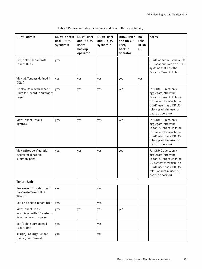
Table 3 Permission table for Tenants and Tenant Units (continued)
DDMC admin DDMC adminand DD OSsysadmin
DDMC userand DD OSuser/backupoperator
DDMC userand DD OSsysadmin
DDMC userand DD OSuser/backupoperator
norolein DDOS
notes
Edit/delete Tenant withTenant Units
yes DDMC admin must have DDOS sysadmin role on all DDsystems that host theTenant's Tenant Units.
View all Tenants defined inDDMC
yes yes yes yes yes
Display issue with TenantUnits for Tenant in summarypage
yes yes yes yes For DDMC users, onlyaggregate/show theTenant's Tenant Units onDD system for which theDDMC user has a DD OSrole (sysadmin, user orbackup operator)
View Tenant Detailslightbox
yes yes yes yes For DDMC users, onlyaggregate/show theTenant's Tenant Units onDD system for which theDDMC user has a DD OSrole (sysadmin, user orbackup operator)
View MTree configurationissues for Tenant insummary page
yes yes yes yes For DDMC users, onlyaggregate/show theTenant's Tenant Units onDD system for which theDDMC user has a DD OSrole (sysadmin, user orbackup operator)
Tenant Unit
See system for selection inthe Create Tenant UnitWizard
yes yes
Edit and delete Tenant Unit yes yes
View Tenant Unitsassociated with DD systemslisted in inventory page
yes yes yes yes
Edit/delete unmanagedTenant Unit
yes yes
Assign/unassign TenantUnit to/from Tenant
yes yes
Administering Secure Multitenancy
Data Domain Secure Multitenancy overview 59
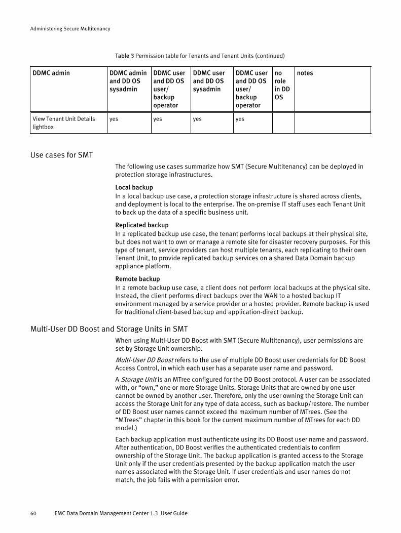
Table 3 Permission table for Tenants and Tenant Units (continued)
DDMC admin DDMC adminand DD OSsysadmin
DDMC userand DD OSuser/backupoperator
DDMC userand DD OSsysadmin
DDMC userand DD OSuser/backupoperator
norolein DDOS
notes
View Tenant Unit Detailslightbox
yes yes yes yes
Use cases for SMTThe following use cases summarize how SMT (Secure Multitenancy) can be deployed inprotection storage infrastructures.
Local backupIn a local backup use case, a protection storage infrastructure is shared across clients,and deployment is local to the enterprise. The on-premise IT staff uses each Tenant Unitto back up the data of a specific business unit.
Replicated backupIn a replicated backup use case, the tenant performs local backups at their physical site,but does not want to own or manage a remote site for disaster recovery purposes. For thistype of tenant, service providers can host multiple tenants, each replicating to their ownTenant Unit, to provide replicated backup services on a shared Data Domain backupappliance platform.
Remote backupIn a remote backup use case, a client does not perform local backups at the physical site.Instead, the client performs direct backups over the WAN to a hosted backup ITenvironment managed by a service provider or a hosted provider. Remote backup is usedfor traditional client-based backup and application-direct backup.
Multi-User DD Boost and Storage Units in SMTWhen using Multi-User DD Boost with SMT (Secure Multitenancy), user permissions areset by Storage Unit ownership.
Multi-User DD Boost refers to the use of multiple DD Boost user credentials for DD BoostAccess Control, in which each user has a separate user name and password.
A Storage Unit is an MTree configured for the DD Boost protocol. A user can be associatedwith, or “own,” one or more Storage Units. Storage Units that are owned by one usercannot be owned by another user. Therefore, only the user owning the Storage Unit canaccess the Storage Unit for any type of data access, such as backup/restore. The numberof DD Boost user names cannot exceed the maximum number of MTrees. (See the“MTrees” chapter in this book for the current maximum number of MTrees for each DDmodel.)
Each backup application must authenticate using its DD Boost user name and password.After authentication, DD Boost verifies the authenticated credentials to confirmownership of the Storage Unit. The backup application is granted access to the StorageUnit only if the user credentials presented by the backup application match the usernames associated with the Storage Unit. If user credentials and user names do notmatch, the job fails with a permission error.
Administering Secure Multitenancy
60 EMC Data Domain Management Center 1.3 User Guide
Managing Tenant users and their privilegesThere is no direct way to create a Tenant user. The only way for a Tenant to have users isby association with its Tenant Units. Tenant users are all users in their own Tenant Units.
Adding a user with an association to DD Boost data access or Tenant self-service usingthe CLI can be dangerous because of cross-tenancy issues. The CLI will not validate usersbelonging to other Tenants when adding DD Boost data access users or Tenant self-service users to the current Tenant.
You can create local users with DD Management Center. If you create a local user with arole of none using the DD System Manager or DD OS CLI, the user will appear in the DDManagement Center list of available users to be added for DD Boost data access and/orTenant self-service.
For more information about creating a user with DD System Manager, see the EMC DataDomain Operating System Administration Guide. For creating a user with the DD OS CLI, seethe EMC Data Domain Operating System Command Reference Guide.
Using DD Management Center to administer SMTIn DD Management Center, SMT (Secure Multitenancy) is administered by selectingAdministration > Multitenancy.
The Administration Multitenancy page shows a Tenant tree on the left, from which youcan create and manage Tenants, Tenant Units, and provisioned storage.
Above this tree are controls to Add (green +), Edit (pencil), and Delete (red X) Tenantsand/or Tenant Units (depending on what is highlighted in the tree), as well as a Tenant(Unit) Details (blue i) icon that displays the Tenant (Unit) Details Lightbox (againdepending on what is highlighted). You can also right-click on each node in the tree toperform these functions, as well. All of these actions are controlled by RBAC (role-basedaccess control).
Also in the tree, each node has a control to its left, indicating its Warning or Offlinestatus. This status rolls up to the Tenant and all Tenant nodes. Additionally controls forcreating, editing, or deleting states are displayed while each operation is in progress.Some actions may not be allowed, depending on the different state or status of thenodes. If there are Tenant Units under a Tenant with the same name, an information iconis displayed for the Tenant node.
The All Tenants node is always displayed and lets you create Tenant objects.
The Unmanaged node is displayed only if there are unmanaged Tenant Units available.The only actions allowed on the Unmanaged node and the Unmanaged Tenant u=Unitsare Add all to Tenant and Add to Tenant, respectively, and are available only through theright-click context menus.
To the right of the tree is a summary.
When All Tenants is selected, the summary shows the total number of Tenants, TenantUnits, and host systems. You can see if any of the Tenants or Tenant Units are offline orhave configuration problems in different severity panels. You can also see the number ofunassigned Tenant Units.
When you select a Tenant or Tenant Unit, the summary includes (depending on the item)the name, status, administrator name and email, host systems, data center location,alerts, and MTree and storage information, DD Boost Users, Tenant Self-Serviceinformation, and Report schedule and recipients.
To generate reports about Tenants or individual Tenant Units, select Reports >Management.
Administering Secure Multitenancy
Managing Tenant users and their privileges 61

To see the general health for Tenants and Tenant Units, select Health > Status, Health >Alerts, and/or Health > Jobs.
To changed a Data Center Location, select Administration > Properties and edit the DataCenter property. Note that each DD system must explicitly be assigned a value for DataCenter in Administration > Systems. If a DD system has a Data Center property assigned, itwill be grouped under All in the Create Tenant Unit wizard.
Storage administrator tasks in SMTStorage administrators are the landlords for backup operators (tenants), in an SMT(Secure Multitenancy) environment. Storage administrators install and configure DDsystem hardware and software and use DD Management Center to provision and assignstorage to the Tenants that they support.
Storage administrators in an SMT environment perform the following tasks:
l Migrate users from multiple small DD systems to one or more larger systems
l Isolate each Tenant's data from other Tenants who share storage on the samephysical DD system
l Monitor and manage the space usage and performance of each system
l Monitor and manage the space usage by, and performance provided to, each Tenant,which ensures that the storage administrator meets the requirements of the servicelevel agreement with each Tenant
l Group together Tenants with similar characteristics on the same physical system togain more cross deduplication
l Charge Tenants based on their space usage
Backup operator tasks in SMTBackup operators are the tenants in an SMT (Secure Multitenancy) environment. Backupoperators are responsible for scheduling and managing backups and replication for theirorganization or department using the storage available in their Tenant Units.
Backup operators in an SMT environment perform the following tasks:
l monitor the performance and resources of their Tenant Units
l monitor replication
l generate reports
Creating and managing TenantsDD Management Center provides many options for creating and managing Tenants.
Creating TenantsYou can create Tenants from the Multitenancy page.
Procedure
1. Select Administration > Multitenancy.
2. Highlight All Tenants in the tree, and select Add Tenant (green plus sign) above thetree.
3. In the Create Tenant dialog, enter the following information:
l For Tenant name [which is required, as indicated by the asterisk (*)], use the nameof the client or organization that will use the storage. For example, if you are a
Administering Secure Multitenancy
62 EMC Data Domain Management Center 1.3 User Guide
service provider, the name might be XYZ Widget Corp. If you are a storageadministrator for an organization, the name might be Finance Department.
l For Administrator name (which is optional), enter the name of the backupadministrator.
l For Administrator email [which is required, as indicated by the asterisk (*)], enterthe email address of the backup administrator. This will be used to create adefault Alert Notification list.
4. Select Create.
Results
The new Tenant appears in the tree.
Viewing Tenant information and statusYou can view information about all Tenants or individual Tenants from the Multitenancypage.
Procedure
1. Select Administration > Multitenancy.
2. Highlight All Tenants to see an overview of the configured Tenants, importantmessages, and the status of multitenant reporting.
3. Highlight a specific Tenant to see the backup administrator's name and emailaddress, important messages about the Tenant Units for this Tenant, and informationabout reports for this Tenant.
4. For much more detail about the Tenant, select Tenant Details (the blue i), above thelist of Tenants, to see all of the available information about the Tenant. The TenantDetails lightbox is described in the next section.
Tenant Details lightboxThe Tenant Details lightbox provides detailed operating information about a specificTenant.
The Tenant Details lightbox is accessed from the Administration > Multitenancy, using theTenant Details control.
The Overview page has the following sections:
l Tenant, which includes Tenant name, Administrator, Administrator email, TenantUnits, and Systems.
l Health, which includes four LEDs for Alerts, File Systems, DD Boost, and Replication.These alerts can be in a Normal, Warning, or Error state. You can hover over an alert toget more information. The Tooltip on the LEDs lists the Tenant Units that haveproblems, along with a link to launch the related DD system for that Tenant Unit.Health LEDs can also be in a disabled state if the underlying component (that is,Replication, DD Boost, etc.) is either not licensed or disabled on any of the DDsystems of the Tenant.
l Capacity, which includes a capacity meter that shows the current utilization,aggregate values for quota available, quota used, quota used % (based on allconfigured MTrees owned by the Tenant), and a warning/error banner, if any of thequotas has not been enabled or configured.
l Replication, which includes counts for both automatic and on-demand replicationpairs: total, with errors, and with unknown status.
Administering Secure Multitenancy
Viewing Tenant information and status 63

l Network Bytes Used, which includes the total, backup, and restore replication bytesused.
The Capacity page shows Capacity Overview details with a variable meter that shows thequota (available, used, and used percentage). The Logical Space Usage chart shows plotsfor Pre-comp used for a selected period of time (24 Hours, 7 Days, 30 Days, 90 Days, orCustom – to set your own time period). There is also a list of Tenant Units associated withthis Tenant with their MTrees or Storage Units, including a severity panel with anywarnings for the MTree/Storage Unit selected.
The Replication page shows Replication Overview details that include the total number ofbytes replicated for Automatic Replication Pairs and On-Demand Replication Pairs. TheReplication Trend chart shows plots for Pre-comp replicated, Post-comp replicated,and/or Compression ratio plots for a selected period of time (24 Hours, 7 Days, 30 Days,90 Days, or Custom – to set your own time period).
The Network page shows Network Overview details that include the last 24 hours of back-up, restored data, and total inbound and outbound replication. The Trend Analysis chartsshow plots for Total Network Used, Backup and Restore Bytes Used, and ReplicationBytes Used for a selected period of time (24 Hours, 7 Days, 30 Days, 90 Days, or Custom– to set your own time period).
The System Charts page shows the system charts for the DD system of a selected TenantUnit associated with this Tenant. Desired charts can be added to the chart area (at theright) by enabling the respective checkboxes. You can display Resource charts for CPUutilization and Network throughput; File system charts for Stream counts, Protocolprocessing, and Protocol throughput; Replication charts for Inbound/Outboundcharacteristics and Throughput for each type of replication. In the chart area, multiplecharts are displayed vertically according to the selection. All of these charts can bedisplayed for a selected period of time (24 Hours, 7 Days, 30 Days, 90 Days, or Custom –to set your own time period).
Editing Tenant informationYou can change Tenant names, administrator names, and administrator email addressesusing the Edit Tenant dialog.
Procedure
1. Select Administration > Multitenancy.
2. In the tree, highlight the Tenant that you want to update, and select Edit Tenant(yellow pencil) above the tree.
3. In the Edit Tenant dialog, edit what you need to change, and select Save.
Results
The edited Tenant will again be displayed in the tree.
Deleting TenantsWhen you no longer need to provide storage for an organization, you can delete theTenant that corresponds to that organization.
Procedure
1. Select Administration > Multitenancy.
2. Highlight the Tenant in the tree, and select Delete Tenant (red X) above the tree.
3. In the Delete Tenant dialog, you have two options:
Administering Secure Multitenancy
64 EMC Data Domain Management Center 1.3 User Guide

l Remove all Tenant Units, which will preserve the data, so that the Tenant Unit maybe assigned to another Tenant. The Tenant Units will be moved to the UnmanagedTenant Unit pool and will retain all MTrees/Storage Units associated with them.
l Destroy all Tenant Units, which will destroy all of the Tenant Units and any MTreesand Storage Units associated with them.
4. Select Yes.
NOTICE
Deleting a Tenant cannot be undone from DD Management Center, so be very carefulwhen performing this task.
Results
The Tenant has been deleted from the tree.
What to do if delete Tenant failsWhen you try to delete a Tenant, the operation may fail for a variety of reasons.
First, go to the Health > Jobs page, select the failed job, and observe the reason for thefailure, which may include:
l The file system of one or more of the DD systems under the Tenant is turned off.
l Some of the DD systems under the Tenant are not reachable or are powered down.
l The DD Boost feature of one or more of the DD systems under the Tenant is disabledor is not licensed.
You can manually fix these problems using both the DD System Manager and the DDManagement Center command line interfaces (you need to fix them in both places, asthey are DD system-related). Then, you can try to delete the Tenant again using DDManagement Center.
Creating and managing Tenant UnitsDD Management Center provides many options for creating and managing Tenant Units.
Creating a new Tenant Unit with the wizardYou can create a Tenant Unit with the Create Tenant Unit Wizard.
Before you begin
Storage for a Tenant is contained within a virtual partition called a Tenant Unit on a DDsystem. To assign storage to a Tenant, you can use the Create Tenant Unit Wizard tocreate the Tenant Unit, provision storage, and assign the Tenant Unit to a Tenant. You canalso create an empty Tenant Unit for a Tenant and provision storage later.Select Administration > Multitenancy. Then select a Tenant, and the Add (green +) control.
You have three choices when creating a Tenant Unit:
l Create a Tenant Unit with manual provisioning, where you create/select the MTreesand Storage Units that will be associated with this Tenant Unit. You can alsooptionally create DD Boost Data Access users to go with the Storage Units.
l Create a Tenant Unit with automatic provisioning, where you can add new or existingDD Boost Data Access users to this Tenant Unit. This will allow backup software tocreate Storage Units that will be assigned to this Tenant Unit.
l Create an empty Tenant Unit, where you can provision the Tenant Unit later using theEdit Tenant Unit dialog.
Administering Secure Multitenancy
Creating and managing Tenant Units 65

Procedure
1. On the first page of the wizard, Identify Host System:
l For Tenant Unit name [which is required, as indicated with the asterisk (*)], enter aunique Tenant Unit name per system.
l For Administrator name (which is optional), enter the name of the backupadministrator.
l For Administrator email [which is required, as indicated with the asterisk (*)], enterthe email address of the backup administrator. This will be used to create adefault Alert Notification list.
l For Datacenter location (which is optional), enter a location. The Tenant Unit willbe created only on systems at this location. This is the same Data Center locationfrom Administration > Properties. The administrator should populate the DataCenter property with values (for example, Dallas, New York, etc.). When adding asystem, this property should be set for the system, depending on its location(example, Dallas). After this value has been set for any system, it will show up inthe drop-down list here (Create Tenant Unit). Selecting it will then filter and showall systems based on only that Data Center location property.
l For Size now (GiB) (which is optional), enter a number to filter systems that do notcurrently have sufficient storage capacity.
l For Size to grow (GiB) (which is optional), enter a number to filter systems that willnot have sufficient capacity at a specified time in the future (set in the next field,“Time to grow”), based on capacity projections. The size to grow is actually thesize to grow to by the specified time. For example, for a specified time of 6 months,if the size now is 1 GiB, and the size to grow is 2 GiB, in six months, the minimumcapacity requirement would be 2 GiB.
l For Time to grow (which is optional), enter the time after which the “Size to grow”amount of capacity should be reached.
2. On the second page of the wizard, Select Host System, you will see systems that haveenough logical capacity to host the Tenant Unit:
l Available now indicates systems that you can select now.
l Available in 6 months is displayed if you selected 6 months in the “Time to grow”field on the previous page, or did not explicitly select a value. Available in 12months, Available in 18 months, or Available in 24 months is displayed if youselected those values in “Time to grow”. For example, for a specified time of 6months, if the size now is 1 GiB, and the size to grow is 2 GiB, in six months, theminimum capacity requirement would be 2 GiB. Any system that has a lowerprojected capacity will be filtered from the list. Also, any system offline at the time,as well as any collection destination system, will be filtered from the list. Also, anysystems running a version prior to DD OS 5.5.x will be filtered from the list, that is,only systems running DD OS 5.5.x or later will be listed.
l Existing Tenant Units displays the current number of Tenant Units on this system.
l For systems with an information (blue i) control, you can hover to see a warningmessage explaining why a projection cannot be made.
l If a DD system is not listed, it may be because it:
n is not in the specified data center.
n is offline.
n is running DD OS 5.3 or earlier.
Administering Secure Multitenancy
66 EMC Data Domain Management Center 1.3 User Guide

n has insufficient capacity.
n has a replication destination.
n is a system for which you do not have administrative privileges.
l For the selected system, the charts at the bottom shows historical data, includingthroughput for selected connection port, CPU utilization for each system, andstream count. You can use this information to determine the best system on whichto create the Tenant Unit.
3. The third page of the wizard depends on your previous choice. [Note that for “Createan empty Tenant Unit”, you will just go to the final page (step 4).]
a. For manual provisioning, you can create MTrees/Storage Units.
l MTrees/Storage Units can be added here, when creating a Tenant Unit withManual Provisioning. You can also add then when editing a Tenant Unit.
l You can add new MTrees or Storage Units, or select from the Existing MTrees orStorage Units on the host system.
l You can also edit, unassign, or destroy MTrees or Storage Units from the samearea.
l If an MTree or Storage Unit selection is disallowed, you can hover the mouseover it, to see more information.
b. For automatic provisioning, you can configure users for data access over the DDBoost protocol.
l You can add an existing local user or create a new local user and promote thelocal user to DD Boost user.
l You can delete the selected DD Boost User.
l The table contains DD Boost Data Access User names and the Storage Unitscount associated with the user.
l The information panel shows when one or more users is selected.
l The configuration is not changed until you select Create on the Summary page.
l If there are one or more local users in the list, the first local user in the list willbe selected by default. If there are no local users in the list, the “New localuser ”will be selected. All selected users or newly created users willautomatically be default Tenant Units.
l A warning will show if the current selected local user already has anotherTenant Unit as their default Tenant Unit.
l The first entry in the “Local user” drop-down list is “New local user”, which letsyou create a new local user and add it as a DD Boost Data Access user.
l When selecting “ New local user”, the Add DD Boost Data Access User dialogwill change to a create new local user form.
4. The fourth (final) page (third page for “Create an empty Tenant Unit”) of the wizard is aSummary, showing data from the previous pages.
l The Tenant Unit is not created until you select Create.
l You have the option to send an email to the Tenant Unit administrator on thesuccessful creation of the Tenant Unit.
l Creating a Tenant Unit with any sort of provisioning (not empty) will automaticallygenerate a pair of Report Templates (Status and Usage) and schedule them.
Administering Secure Multitenancy
Creating a new Tenant Unit with the wizard 67

l You may get one of two warnings: (1) You have not provisioned this Tenant Unitcorrectly. Add MTrees or Storage. (2) You have not provisioned this Tenant Unitcorrectly. Make this Tenant Unit the Default Tenant Unit for one of the DD BoostData Access Users.
Results
The newly created Tenant Unit is added to the tree.
What to do if create Tenant Unit failsCreating a Tenant Unit may fail for a number of reasons.
It may fail for simple reasons such as a duplicate Tenant Unit name, or it may fail if thereare network/connectivity issues, sudden system state changes, etc.
Within the create process itself, there may be failures where MTrees or Storage Units mayfail to get created for one or more reasons, or DD Boost users may not get created.
Creating a Tenant Unit will succeed even if the configuration of an individual componentlike MTrees or DD Boost users fails. So, the final components of a newly created TenantUnit might not match your specifications.
To see the success and/or failed information for each individual task, or if there is aninconsistency in what you expected and what was created, select Health > Jobs to seeadditional messages.
You must address the reasons for failure before trying to re-create a new Tenant Unit, oryou risk seeing the same failure situations again.
Viewing Tenant Unit information and statusYou can view information about all Tenant Units from the Multitenancy page.
Procedure
1. Select Administration > Multitenancy.
2. Select a Tenant Unit in the tree to view a summary page and critical alerts.
3. For more detail about the Tenant Unit, select Tenant Unit Details (the blue i), abovethe tree, to see all of the available information about the Tenant Unit. The Tenant UnitDetails lightbox is described in the next section.
Tenant Unit Details lightboxThe Tenant Unit Details lightbox provides detailed operating information about a specificTenant Unit.
The Tenant Unit Details lightbox can be accessed from the Administration > Multitenancy,Health > Status, or Health > Alerts page (Tenants View), using the Tenant Unit Detailscontrol.
The Overview page has the following sections:
l Tenant Unit, which includes Tenant Unit name, Administrator, Administrator email,Host System, and Data Center Location.
l Health, which includes four LEDs for Alerts, File Systems, DD Boost, and Replication.These alerts can be in a Normal, Warning, or Error state. You can hover over an alert toget more information. Health LEDs can also be in a disabled state if the underlyingcomponent (that is, Replication, DD Boost, etc.) is either not licensed or disabled forthe DD system of the selected Tenant Unit.
l Host System Performance Details, which shows data flow for Throughput, CPU andStream Count. Different network ports can be selected. Chart durations can beselected among: Last 24 Hours, 7 Days, 30 Days, 90 Days, and Custom.
Administering Secure Multitenancy
68 EMC Data Domain Management Center 1.3 User Guide
l Capacity, which includes a capacity meter that shows the current utilization,aggregate values for quota available, quota used, quota used % (based on allconfigured MTrees owned by the Tenant Unit), and a warning/error banner, if any ofthe quotas has not been enabled or configured.
l Replication, which includes counts (inbound and outbound) for both automatic andon-demand replication pairs: total, with errors, and with unknown status.
l Network Bytes Used, which includes the total, backup, and restore replication bytesused.
The Capacity page shows Capacity Overview details with a variable meter that shows thequota used percentage; a Logical Space Usage chart that can be scaled to view certainperiods of usage; and a list of Tenant Units with their MTrees or Storage Units, including aseverity panel with any warnings for the MTree/Storage Unit selected.
The Replication page shows Replication Overview details that include the total number ofbytes replicated for Automatic Replication Pairs and On-Demand Replication Pairs. TheReplication Trend chart shows at least one of: Pre-comp replicated, Post-comp replicated,and Compression ratio plots in a customized time plot.
The Network page shows Network Overview details that include the last 24 hours of back-up, restored data, and total inbound and outbound replication. The Trend Analysis showscharts that can be viewed for a certain period by selecting one of the four options (24Hours, 7 Days, 30 Days, 90 Days) or by selecting Custom, which lets you select a differenttime frame.
The System Charts page shows the system charts for the DD system of the selectedTenant Unit. Desired charts can be added to the chart area (at the right) by enabling therespective checkboxes. You can display Resource charts for CPU utilization and Networkthroughput; File system charts for Stream counts, Protocol processing, and Protocolthroughput; Replication charts for Inbound/Outbound characteristics and Throughput foreach type of replication. In the chart area, multiple charts are displayed verticallyaccording to the selection.
Editing Tenant Unit informationYou can change all types of information for both managed and unmanaged Tenant Unitsusing the Edit Tenant Unit dialog.
Procedure
1. Select Administration > Multitenancy.
2. Highlight the Tenant Unit in the tree, and select Edit Tenant Unit (yellow pencil) abovethe tree.
3. The Edit Tenant Unit dialog has the following tabs: General, Alert Notifications,DDBoost Data Access Users, MTrees, and Tenant Self-Service, which are described inthe following sections.
Editing Tenant Units: General tabYou can change administrative information for both managed and unmanaged TenantUnits using the General tab in the Edit Tenant Unit dialog.
Procedure
1. Select Administration > Multitenancy.
2. Highlight a Tenant Unit in the tree, and select Edit Tenant Unit (yellow pencil) abovethe tree.
3. In the General tab, you can change the following:
Administering Secure Multitenancy
Editing Tenant Unit information 69

l Tenant Unit name
l Administrator name
l Administrator email – If the administrator email is modified, report templatessending reports associated with the Tenant Unit to that administrator need to bere-routed. After editing the administrator email, a popup appears confirmingwhether a change needs to be made for all report templates associated with theold email. If you select Yes, all old administrator emails will be replaced with thenew value.
Editing Tenant Units: Alert Notifications tabEach Tenant Unit has a default alert notification list (created by the DD system)containing the administrator email. You can create new alert notification lists, editexisting lists, or delete lists associated with the Tenant Unit, using the Alert Notificationstab in the Edit Tenant Unit dialog.
Procedure
1. Select Administration > Multitenancy.
2. Highlight a Tenant Unit in the tree, and select Edit Tenant Unit (yellow pencil) abovethe tree.
3. In the Alert Notifications tab, select Add (green plus sign).
4. In the Add Alert Notification Group dialog, enter a name for the notification group.
5. Select Add (green plus sign), and enter the first email address.
Optionally, continue selecting Add to enter more addresses.
6. Select Add at the bottom of the dialog when you have finished adding addresses, andthen select OK or Apply to save your changes.
Editing Tenant Units: DD Boost Data Access Users tabDD Boost Data Access Users are users that are configured for specific Tenant Units (oneor more user per Tenant Unit). You can optionally designate a Tenant Unit as the defaultStorage Unit for a DD Boost Data Access User. When your backup software creates newStorage Units for a user, the software automatically uses the default Tenant Unit.
Procedure
1. Select Administration > Multitenancy.
2. Highlight a Tenant Unit in the tree, and select Edit Tenant Unit (yellow pencil) abovethe tree.
3. In the DDBoost Data Access Users tab, add, edit, or delete users, as desired. New DDBoost users are assigned the role of none. If a user has already been created with arole other than none, that user is disabled and can only be deleted from the table.Also, if a user has already been associated with multiple Tenants, that user isdisabled and can only be deleted from the table. Password validation for a new localuser is based on the DD OS password policy strength associated with the currentTenant Unit.
4. Select OK or Apply to save your changes.
Administering Secure Multitenancy
70 EMC Data Domain Management Center 1.3 User Guide
Editing Tenant Units: DDBoost Streams tabYou can limit the number of streams an application can use when reading or writing datato a Storage Unit. If a client uses more than the set limit, an alert will be generated by theDD system.
Procedure
1. Select Administration > Multitenancy.
2. Highlight a Tenant Unit in the tree, and select Edit Tenant Unit (yellow pencil) abovethe tree.
3. In the DDBoost Streams tab, view the Storage Units associated with this Tenant Unit.
4. If you want to set limits for a Storage Unit, select that unit, and then select Set Limits.
Configuring DD Boost soft stream limits
You can configure soft stream warning limits for each Storage Unit for four items: Read,Write, Replication, and Combined. When any of these stream counts exceeds the warninglimit, an alert is generated.
Procedure
1. Select Set Limits from the DDBoost Streams tab of the Edit Tenant Unit dialog [whichyou can get to by selecting Administration > Multitenancy, then selecting a Tenant Unitand Edit Tenant Unit (yellow pencil)].
2. In the Set DDBoost Stream Limits dialog, enter values for the Read, Write, Replication,and Combined stream limits. Do not exceed the DD System Limits, listed at right. Alsonote that a single value cannot be larger than the Combined limit.
3. Then, if the limits are surpassed, an alert will be generated by the DD System.
4. Select Set.
Editing Tenant Units: MTrees tabYou can create and manage MTrees and Storage Units using the MTrees tab in the EditTenant Unit dialog. In addition to this method, you can also add MTrees and StorageUnits when you are creating a Tenant Unit with Manual Provisioning.
Procedure
1. Select Administration > Multitenancy.
2. Highlight a Tenant Unit in the tree, and select Edit Tenant Unit (yellow pencil) abovethe tree.
3. In the MTrees tab, add, edit, or delete MTrees and/or Storage Units, as desired.
Adjusting soft/hard quotas for MTrees and Storage Units
Quotas can be enabled or disabled on a host system using the command line interface(CLI) or with DD System Manager. You cannot enable or disable quotas using DDManagement Center. You can adjust quotas using DD Management Center if the hostsystem quotas have already been enabled.
Before you begin
The host system quotas must have already been enabled.
Procedure
1. Select Administration > Multitenancy.
Administering Secure Multitenancy
Editing Tenant Unit information 71

2. Highlight the Tenant Unit in the tree, and select Edit Tenant Unit (yellow pencil) abovethe tree.
3. In the MTrees tab, highlight a Storage Unit or MTree in the list, and select Edit (yellowpencil).
4. Set the desired quota values in the Edit MTree or Edit Storage Unit dialog, and selectSave.
5. Select OK or Apply to save your changes.
After you finish
You can also enable or disable quotas on the host system by:
1. Launch the DD System Manager, for the specific DD system, from DD ManagementCenter.
2. Select Data Management > Quota tab.
3. Enable or disable quotas, as needed.
You can also enable or disable quotas using the CLI. See the EMC Data Domain OperatingSystem Command Reference Guide.
Editing Tenant Units: Tenant Self-Service tabTenant Self-Service lets a Tenant log in to a DD system to access the Tenant Unitsassigned to him/her and perform his/her own administration and reporting for his/herown environment. Tenant Users and Tenant Admins will, of course, have differentprivileges.
Procedure
1. Select Administration > Multitenancy.
2. Highlight a Tenant Unit in the tree, and select Edit Tenant Unit (yellow pencil) abovethe tree.
3. In the Tenant Self-Service tab, you must first enable Tenant Self-Service, if it disabled(which is it by default).
4. Note that in this table:
l The Type column displays management-user or management-group.
l The Role column displays tenant-admin or tenant-user.
5. To add a self-service user, select Add (green plus sign). In the Add Self-Service Userdialog, select the desired local user, NIS group, or AD group, or create a new local user(there is no default). If you select New local user, the dialog will add fields for Name,Password/Confirm, and Role (tenant-admin or tenant-user). Password validation for anew local user is based on the DD OS password policy strength associated with thecurrent Tenant Unit.
6. To edit a self-service user, select a User or Group, and select Edit (yellow pencil). Youcan change the Role from tenant-admin to tenant-user, or vice-versa.
7. To delete a self-service user, select a User or Group, and select Delete (X). You will geta confirmation dialog to make sure that you definitely want to delete this user orgroup. A new Tenant self-service user or group is assigned the role of none. If a user orgroup has already been created with a role other than none, that user or group isdisabled and can only be deleted from the table. Also, If a user or group has alreadybeen associated with multiple Tenants, that user or group is disabled and can only bedeleted from the table.
Administering Secure Multitenancy
72 EMC Data Domain Management Center 1.3 User Guide
Deleting Tenant Units and unassigning provisioned storageYou can delete Tenant Units, and if a Tenant Unit has provisioned storage, you canunassign that storage to be reassigned later to another Tenant Unit, or you can destroy allof the data. Be very careful when performing this task – it cannot be undone.
Procedure
1. Select Administration > Multitenancy.
2. Highlight a Tenant Unit in the tree, and select Delete Tenant Unit (red X) above thetree.
3. In the Delete Tenant Unit dialog, if the Tenant Unit has provisioned storage, you havetwo options:
l Unassign all storage, which retains all MTrees and Storage Units associated withthe Tenant Unit, so they can be reassigned later to another Tenant Unit.
l Destroy all storage, which deletes all MTrees and Storage Units associated withthe Tenant Unit.
4. Select Yes to delete the Tenant Unit.
5. Observe that the Tenant Unit has been deleted from the tree.
What to do if delete Tenant Unit failsWhen you try to delete a Tenant Unit, the operation may fail for a variety of reasons.
First, go to the Health > Jobs page, select the failed job, and observe the reason for thefailure, which may include:
l The file system of the DD system on which the Tenant Unit resides is turned off.
l The DD system on which the Tenant Unit resides is not reachable or is powereddown.
l The DD Boost feature of the DD system on which the Tenant Unit resides isdisabled or is not licensed.
You can manually fix these problems using both the DD System Manager and the DDManagement Center command line interfaces (you need to fix them in both places, asthey are DD system-related). Then, you can try to delete the Tenant Unit again usingDD Management Center.
Adding an unmanaged Tenant Unit to a TenantWorking from the DD OS CLI (command-line interface), administrators can create TenantUnits without adding them to tenants. These Tenant Units are referred to as unmanaged.In DD Management Center, you cannot create an unmanaged Tenant Unit, but you canadd an unmanaged Tenant Unit to a tenant.
Procedure
1. Select Administration > Multitenancy.
2. Select the Unmanaged node in the tree. A table is displayed on the right, whichcontains all unmanaged Tenant Units and the host systems on which they reside.
3. To add all unmanaged Tenant Units to a Tenant, right-click the Unmanaged node, andselect Add all to Tenant. In the Add (All) Tenant Units dialog, select the Tenant name,and select Add.
4. If you want to add only a specific Tenant Unit or Units to a Tenant, go back to the tableto select the checkbox or checkboxes next to them. Or to select a single Tenant Unit,
Administering Secure Multitenancy
Deleting Tenant Units and unassigning provisioned storage 73

and see a summary about it, you can expand the Unmanaged list (if it is not alreadyexpanded), and select a single Tenant Unit.
5. At the top right, select the Add to Tenant link.
6. In the Add Tenant Unit(s) dialog, select a Tenant name, and select Add. The TenantUnit will be moved from the Unmanaged node to the selected Tenant, in the tree.
After you finish
You may encounter a potential conflict when trying to assign a Tenant Unit.Suppose you have a DD Boost user, or Tenant self-service user, configured under acurrent unmanaged Tenant Unit. If the same user is configured to the managed TenantUnit of Tenant T2, but you want to assign the Tenant Unit to Tenant T1, this is considereda conflict and is not allowed.
Creating, editing, and generating reports for SMTYou can create, edit, and generate reports for SMT (Secure Multitenancy) using DDManagement Center.
SMT report permission tablePermissions for working with creating and viewing reports for Tenants and Tenant Unitsdepend on the role of the user in both DD Management Center and on the DD system (DDOS).
Table 4 Permission table for Tenants and Tenant Units
DDMC admin DDMC adminand DD OSsysadmin
DDMC userand DD OSuser/backupoperator
DDMC userand DD OSsysadmin
DDMC userand DD OSuser/backupoperator
norole inDD OS
notes
Report Template
View all report templates yes yes DDMC user can view onlytemplates or reports thatthey created.
View Tenant reportconfiguration informationin summary page
yes yes Only DDMC admin shouldbe allowed to createTenant report template.
View Tenant Unit reportconfiguration informationin summary page
yes yes yes yes
Create Auto Tenant reporttemplate
yes yes
Create Auto Tenant Unitreport template
yes yes yes yes
Create Manual Tenantreport template
yes yes DDMC user is not allowedto manually create aTenant report template.
Administering Secure Multitenancy
74 EMC Data Domain Management Center 1.3 User Guide

Table 4 Permission table for Tenants and Tenant Units (continued)
DDMC admin DDMC adminand DD OSsysadmin
DDMC userand DD OSuser/backupoperator
DDMC userand DD OSsysadmin
DDMC userand DD OSuser/backupoperator
norole inDD OS
notes
Create Manual Tenant Unitreport template
yes yes yes yes
Maintain and tag SMTreport templateconfiguration
yes yes yes yes If the reports of a DDMCuser are deleted, thatuser is warned, and thereports are re-createdand tagged for that useronly.
Creating report templates for SMTSMT (Secure Multitenancy) report templates configure daily status and usage metrics forTenants and Tenant Units.
Note
If a user who is the “owner” of any report templates is deleted from DD ManagementCenter, those report templates will still appear to be owned by the “deleted” user, but thereports will no longer run at their scheduled times.
Procedure
1. Select Reports > Management.
2. Select Add (green plus sign).
3. In the Add Report Template dialog, select Multitenancy Reports and select Next.
4. Enter a name, and select a template. The template choices are Daily Status or UsageMetrics. Choose one or more Sections to include, and select Next.
5. Select a Scope (Tenant Unit or Tenant). The Daily Status report is always configured toshow the last 24 hours of historical data, and you can select the Report retention(Forever, 7 days, 30 days, 90 days). The Usage Metrics report (which is generated asan Excel spreadsheet) lets you display data for a full month or a full week. Select Editto set a schedule for the frequency and time the report is run. Report generation timewill be two hours ahead of Starts On time.
6. For the Tenant Unit report template, the Tenant Unit admin emails will be added bydefault. For the Tenant report template, the Tenant admin email will be added bydefault. You can manually add or remove these emails.
7. Review the details, and select whether to save the template for later use and/or to runthe report immediately. Select Finish.
Results
After it has been created, a multitenancy report template is added as an entry in thereports table. When selected, the template can be used to immediately run a report, or itcan be edited or deleted, or the time it was last run can be displayed.
Administering Secure Multitenancy
Creating report templates for SMT 75
Editing report templatesYou can reconfigure a report template using the Edit control. The report's content,schedule, and email distribution can be modified in the template.
Procedure
1. Select Reports > Management.
2. Select a template, and select Edit (yellow pencil). In the Edit Report dialog, you canselect from three tabs.
3. In the Content tab, the template name can be renamed and template sections can bere-selected for the report. Note that the template, itself, is not editable.
4. In the Scope tab, the template scope and schedule can be changed. The reporttemplate can be changed from a Tenant report to a Tenant Unit report or from a TenantUnit report to a Tenant report. For the daily status report template, the schedule canbe changed only to daily time. For the usage report template, the time span can beweekly or monthly. If time span is weekly, only weekly can be scheduled for start ontime, and if time span is monthly, only monthly time can be scheduled for start ontime. Both daily status and usage report templates can modify the report retentionperiod (Forever, 7 days, 30 days, 90 days).
5. In the Email tab, emails can be manually added or removed from the When report isfinished list or/and from the If an error occurs list.
Generating reportsA report can be generated after the last step of the create report wizard or, as describedbelow, by selecting a report template listed in the Template name table, and selectingRun Report.
Procedure
1. Select Reports > Management.
2. Select a report template from the list.
3. Right-click on the name, and select Run Report.
Results
A report (named by concatenating the datestamp to the template title) is created andopened as a PDF file in your browser, except for the Tenant Usage report, which isgenerated as an Excel file.
The report generation information is listed in the Report History table, where it can beviewed, renamed, or deleted.
Administering Secure Multitenancy
76 EMC Data Domain Management Center 1.3 User Guide

CHAPTER 6
Performing Additional Configuration
l Managing access to DD Management Center......................................................... 78l Viewing active users..............................................................................................93l Managing network settings................................................................................... 93l Upgrading DD Management Center software........................................................104l Checking a DD Management Center serial number...............................................105l Managing alerts.................................................................................................. 105l Managing general configuration settings.............................................................108l Managing autosupport reporting......................................................................... 115l Managing system logs.........................................................................................116
Performing Additional Configuration 77
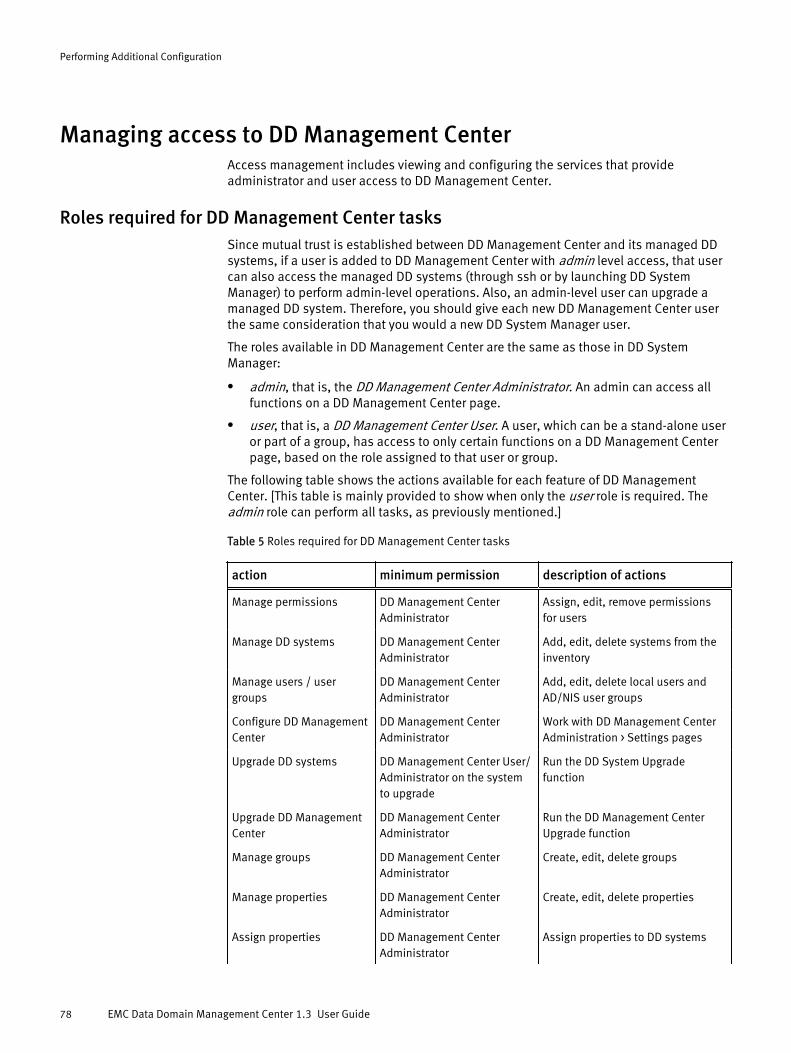
Managing access to DD Management CenterAccess management includes viewing and configuring the services that provideadministrator and user access to DD Management Center.
Roles required for DD Management Center tasksSince mutual trust is established between DD Management Center and its managed DDsystems, if a user is added to DD Management Center with admin level access, that usercan also access the managed DD systems (through ssh or by launching DD SystemManager) to perform admin-level operations. Also, an admin-level user can upgrade amanaged DD system. Therefore, you should give each new DD Management Center userthe same consideration that you would a new DD System Manager user.
The roles available in DD Management Center are the same as those in DD SystemManager:
l admin, that is, the DD Management Center Administrator. An admin can access allfunctions on a DD Management Center page.
l user, that is, a DD Management Center User. A user, which can be a stand-alone useror part of a group, has access to only certain functions on a DD Management Centerpage, based on the role assigned to that user or group.
The following table shows the actions available for each feature of DD ManagementCenter. [This table is mainly provided to show when only the user role is required. Theadmin role can perform all tasks, as previously mentioned.]
Table 5 Roles required for DD Management Center tasks
action minimum permission description of actions
Manage permissions DD Management CenterAdministrator
Assign, edit, remove permissionsfor users
Manage DD systems DD Management CenterAdministrator
Add, edit, delete systems from theinventory
Manage users / usergroups
DD Management CenterAdministrator
Add, edit, delete local users andAD/NIS user groups
Configure DD ManagementCenter
DD Management CenterAdministrator
Work with DD Management CenterAdministration > Settings pages
Upgrade DD systems DD Management Center User/Administrator on the systemto upgrade
Run the DD System Upgradefunction
Upgrade DD ManagementCenter
DD Management CenterAdministrator
Run the DD Management CenterUpgrade function
Manage groups DD Management CenterAdministrator
Create, edit, delete groups
Manage properties DD Management CenterAdministrator
Create, edit, delete properties
Assign properties DD Management CenterAdministrator
Assign properties to DD systems
Performing Additional Configuration
78 EMC Data Domain Management Center 1.3 User Guide

Table 5 Roles required for DD Management Center tasks (continued)
action minimum permission description of actions
Assign to groups DD Management CenterAdministrator
Assign DD systems to groups
Manage reports DD Management CenterAdministrator
Create report templates andschedule report creation
Manage dashboardwidgets
DD Management CenterAdministrator
Create dashboard widgets
Configure dashboard DD Management CenterAdministrator
Configure widgets and dashboardlayouts
Manage global filter rules DD Management Center User Add, edit, delete filter rules
Launch DD SystemManager
DD Management Center User Launch the virtual DD SystemManager [note that Administratorprivilege is required on themanaged DD system to changeanything]
Manage user jobs DD Management Center User Suspend, resume, cancel jobsowned by user
Manage all jobs DD Management CenterAdministrator
Suspend, resume, cancel any job
Manage advancedreplication
DD Management CenterAdministrator
View replication status, export toCVS file, assign properties
Manage basic replication DD Management Center User View replication status, export toCVS file
Managing administrator accessAdministrator Access provides settings to configure how users can connect to DDManagement Center. Each protocol is configured separately, using the procedures in thissection.
Procedure
1. Select Administration > Settings > Access tab > Administrator Access tab.
2. View the Passphrase, if it is set, or set it, if not. The Passphrase is a human-readable(understandable) key – like a smart card – which is used to generate a machine-usable AES 256 encryption key. (For more information, see the EMC Data DomainOperating System Administration Guide.) You can also view the available services, andfor a selected service, the service options that are configured for it.
Table 6 Services
item description
Name Name of a service/protocol that can access the system. One of thefollowing protocols can be selected (for viewing or configuring): FTP,FTPS, HTTP/HTTPS, SCP/SSH, or Telnet.
Performing Additional Configuration
Managing administrator access 79

Table 6 Services (continued)
item description
Enabled Status of the service: either enabled or disabled.
Allowed Hosts Access permissions set for the named host.
Table 7 Service options
service name option name description
FTP Session Timeout Configured number of elapsed seconds before the servicetimes out, or Infinite.
FTPS Session Timeout Configured number of elapsed seconds before the servicetimes out, or Infinite.
HTTP/HTTPS HTTP/HTTPS port If applicable, port number opened for the HTTP/HTTPSprotocol (HTTP – port 80, by default; HTTPS – port 443, bydefault).
Session Timeout Configured number of elapsed seconds before the servicetimes out, or Infinite.
SCP/SSH SCP/SSH port If applicable, port number opened for the SCP/SSH protocol(port 22, by default).
Session Timeout Configured number of elapsed seconds before the servicetimes out, or Infinite.
Telnet Session Timeout Configured number of elapsed seconds before the servicetimes out, or Infinite.
Managing FTP accessYou can provide access to DD Management Center through an FTP connection.
Procedure
1. Select Administration > Settings > Access tab > Administrator Access tab.
2. In the Services are, select the checkbox next to FTP, and select Configure.
3. In the Configure FTP Access dialog, select Allow FTP Access. If FTPS is enabled, it willbe disabled before enabling FTP.
4. Determine how hosts are to connect:
l Allow all hosts to connect
l Limit access to the following systems – Then, select the appropriate icon underAllowed Hosts. Host names can be a fully qualified host name or an IP address.
n To add a host, select Add (green plus sign). Enter the host name, and selectOK.
n To modify a host name, select the checkbox next to the host name in the Hostslist, select Edit (pencil), change the host name, and select OK.
n To remove a host name, select the checkbox next to the host name in the Hostslist, select Delete (X), and select OK.
Performing Additional Configuration
80 EMC Data Domain Management Center 1.3 User Guide

5. To configure a session timeout value, select the Advanced tab.
6. In Session Timeout, enter, in seconds, the interval that must elapse before theconnection closes, or choose the default of Infinite. To return to default values, selectthe Default button.
7. Select OK.
Managing FTPS accessYou can provide access to DD Management Center through an FTPS connection.
Procedure
1. Select Administration > Settings > Access tab > Administrator Access tab.
2. In the Services panel, select the checkbox next to FTPS, and select Configure.
3. In the Configure FTPS Access dialog, select Allow FTPS Access. If FTP is enabled, it willbe disabled before FTPS is enabled.
4. Determine how hosts are to connect:
l Allow all hosts to connect
l Limit access to the following systems – Then, select the appropriate icon underAllowed Hosts. Host names can be a fully qualified host name or an IP address.
n To add a host, select Add (green plus sign). Enter the host name, and selectOK.
n To modify a host name, select the checkbox next to the host name in the Hostslist, select Edit (pencil), change the host name, and select OK.
n To remove a host name, select the checkbox next to the host name in the Hostslist, select Delete (X), and select OK.
5. To configure a session timeout value, select the Advanced tab.
6. In Session Timeout, enter, in seconds, the interval that must elapse before theconnection closes, or choose the default of Infinite. To return to default values, selectthe Default button.
7. Select OK.
Managing HTTP/HTTPS accessYou can provide access to DD Management Center through an HTTP and/or HTTPSconnection.
Procedure
1. Select Administration > Settings > Access tab > Administrator Access tab.
2. In the Services area, select the checkbox next to HTTP or HTTPS, and select Configure.
3. In the Configure HTTP/HTTPS Access dialog, select the checkbox for Allow HTTPAccess and/or Allow HTTPS Access.
4. Determine how hosts are to connect:
l Allow all hosts to connect
l Limit access to the following systems – Then, select the appropriate icon underAllowed Hosts. Host names can be a fully qualified host name or an IP address.
n To add a host, select Add (green plus sign). Enter the host name, and selectOK.
n To modify a host name, select the checkbox next to the host name in the Hostslist, select Edit (pencil), change the host name, and select OK.
Performing Additional Configuration
Managing administrator access 81
n To remove a host name, select the checkbox next to the host name in the Hostslist, select Delete (X), and select OK.
5. To configure system ports and session timeout values, select the Advanced tab.
l For HTTP Port, enter the port for connection. Port 80 is assigned by default.
l For HTTPS Port, enter the port for connection. Port 443 is assigned by default.
l For Session Timeout, enter, in seconds, the interval that must elapse before theconnection closes. 10800 seconds (3 hours) is assigned by default.
Note
Select Default to return a setting back to its default value.
6. Select OK.
Managing SCP/SSH accessYou can provide access to DD Management Center through an SCP and/or SSHconnection.
Procedure
1. Select Administration > Settings > Access tab > Administrator Access tab.
2. In the Services area, select the checkbox next toSCP or SSH, and select Configure.
3. In the Configure SSH/SCP Access dialog, select options to allow SSH or SCP (or both)access. SCP cannot be enabled unless SSH is enabled, as well.
4. Determine how hosts are to connect:
l Allow all hosts to connect
l Limit access to the following systems – Then, select the appropriate icon underAllowed Hosts. Host names can be a fully qualified host name or an IP address.
n To add a host, select Add (green plus sign). Enter the host name, and selectOK.
n To modify a host name, select the checkbox next to the host name in the Hostslist, select Edit (pencil), change the host name, and select OK.
n To remove a host name, select the checkbox next to the host name in the Hostslist, select Delete (X), and select OK.
5. To configure a session timeout value, select the Advanced tab.
6. In SSH/SCP Port, enter the port number. In Session Timeout, enter, in seconds, theinterval that must elapse before the connection closes, or choose the default ofInfinite. To return to default values, select the Default button.
7. Select OK.
Managing Telnet accessYou can provide access to DD Management Center through a Telnet connection.
Procedure
1. Select Administration > Settings > Access tab > Administrator Access tab.
2. In the Services area, select the checkbox next to Telnet, and select Configure.
3. In the Configure Telnet Access dialog, select the Allow Telnet Access checkbox.
Performing Additional Configuration
82 EMC Data Domain Management Center 1.3 User Guide

4. Determine how hosts are to connect:
l Allow all hosts to connect
l Limit access to the following systems – Then, select the appropriate icon underAllowed Hosts. Host names can be a fully qualified host name or an IP address.
n To add a host, select Add (green plus sign). Enter the host name, and selectOK.
n To modify a host name, select the checkbox next to the host name in the Hostslist, select Edit (pencil), change the host name, and select OK.
n To remove a host name, select the checkbox next to the host name in the Hostslist, select Delete (X), and select OK.
5. To configure a session timeout value, select the Advanced tab.
6. In Session Timeout, enter, in seconds, the interval that must elapse before theconnection closes, or choose the default of Infinite. To return to default values, selectthe Default button.
7. Select OK.
Managing local user access to DD Management CenterThe extent to which you can manage local user access to DD Management Centerdepends on your role.
If you are an administrator on DD Management Center, you become a globaladministrator, and you can configure and monitor all managed DD systems.
If you are a user on DD Management Center, you can view only the managed DD systemsto which you have been assigned a user or admin role by a DD Management Centeradministrator.
Viewing local user informationThe datestamps in the user-authentication module use Greenwich Mean Time (GMT).Therefore, when configuring expiration dates for disabling a user’s account andpassword, the expiration date should reflect GMT instead of local time.
Procedure
1. Select Administration > Settings > Access tab > Local Users tab.
2. On the Local Users page, view information for the configured users.
item description
Name User ID, as added to the system.
Management Role Possible roles of users based on a set of privileges:
l admin role: Can configure and monitor the entire DD system.
l user role: Can monitor DD systems and perform the fastcopyoperation.
Users with admin roles can view all users. Users with user roles canview only their own user account.
Status l enabled – User access to the account is permitted.
l disabled – User access to the account is denied because theexpiration date for the account has been reached or a locked
Performing Additional Configuration
Managing local user access to DD Management Center 83

item description
account’s password has not been renewed. Admin users candisable/enable users with admin or user roles, except SysAdminUser. No users can disable SysAdmin. Security officers candisable/enable only other security officers.
l locked – User access to the account is denied because thepassword has expired.
Disable Date Date the account is set to be disabled.
Last Login From Location where the user last logged in.
Last Login Time Time the user last logged in.
3. Select a specific user to see Detailed Information.
item description
Password Last Changed Date the password was last changed.
Minimum Days BetweenChange
Minimum number of days between password changes that you allowa user. Default is 0.
Maximum Days BetweenChange
Maximum number of days between password changes that you allowa user. Default is 90.
Warn Days Before Expire Number of days to warn the users before their password expires.Default is 7.
Disable Days After Expire Number of days after a password expires to disable the user account.Default is never.
Note
The default password policy can be changed by an admin by selecting More Tasks >
Change Login Options. Default values are the initial default password policy values.
User rolesRoles provide a way to restrict user access to system functions by using a set ofprivileges. Permissions allow an admin access to specific groups and systems, reducingthe need to configure every user as a global admin.
DD Management Center supports the following roles:
l admin role: This role can configure and monitor the entire DD Management Centersystem.
Note
It is recommended that the admin role be used judiciously and awarded to very fewusers, as these users will be able to configure DD Management Center as well as haveaccess to all registered DD systems.
l user role: This role can monitor DD Management Center and DD systems for which theuser has permission.
Performing Additional Configuration
84 EMC Data Domain Management Center 1.3 User Guide

Creating local usersYou can create new users with either the admin or the user role.
Procedure
1. SelectAdministration > Settings > Access tab > Local Users tab.
2. Select Create.
3. In the Create User dialog, enter the following in the General tab:
Table 8 General tab
item description
User User ID or name.
Password User password. Set a default password, and the user can change itlater. The default value for the minimum length of a password orminimum number of character classes required for a user password is1. Allowable character classes include:
l lowercase letters (a-z)
l uppercase letters (A-Z)
l numbers (0-9)
l special characters ($, %, #, +, and so on)
Verify Password User password, again.
Management Role Management role assigned to the user:
l admin role: Can configure and monitor the entire DD ManagementCenter and all DD systems.
l user role: Can monitor DD Management Center and DD systemsfor which they have permission.
4. Enter the following in the Advanced tab:
Performing Additional Configuration
Managing local user access to DD Management Center 85

Table 9 Advanced tab
item description
Minimum Days BetweenChange
Minimum number of days between password changes that you allowa user. Default is 0.
Maximum Days BetweenChange
Maximum number of days between password changes that you allowa user. Default is 99999.
Warn Days Before Expire Number of days to warn the users before their password expires.Default is 7.
Disable Days After Expire Number of days after a password expires to disable the user account.Default is Never.
Disable account on thefollowing date
Check this box and enter a date (mm/dd/yyyy) when you want todisable this account. Also, you can click the calendar to select a date.This date uses GMT.
5. Select OK.
Note
The default password policy can be changed by the admin using More Tasks > ChangeLogin Options. The default values are the initial default password policy values.
Modifying a local user profileYou can modify several aspects of a local user profile.
Procedure
1. Select Administration > Settings > Access tab > Local Users tab.
2. Select a user name, and select Modify.
3. In the Modify User dialog, change the assigned role.
4. Enter the following information in the Advanced tab:
Table 10 Advanced tab
item description
Minimum Days BetweenChange
Minimum number of days between password changes that you allowa user. Default is 0.
Maximum Days BetweenChange
Maximum number of days between password changes that you allowa user. Default is 99999.
Warn Days Before Expire Number of days to warn the users before their password expires.Default is 7.
Disable Days After Expire Number of days after a password expires to disable the user account.Default is Never.
5. Optionally, configure a disable date (which uses GMT) for the user account.
6. Select OK.
Performing Additional Configuration
86 EMC Data Domain Management Center 1.3 User Guide
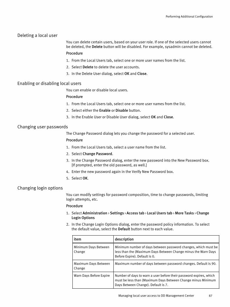
Deleting a local userYou can delete certain users, based on your user role. If one of the selected users cannotbe deleted, the Delete button will be disabled. For example, sysadmin cannot be deleted.
Procedure
1. From the Local Users tab, select one or more user names from the list.
2. Select Delete to delete the user accounts.
3. In the Delete User dialog, select OK and Close.
Enabling or disabling local usersYou can enable or disable local users.
Procedure
1. From the Local Users tab, select one or more user names from the list.
2. Select either the Enable or Disable button.
3. In the Enable User or Disable User dialog, select OK and Close.
Changing user passwordsThe Change Password dialog lets you change the password for a selected user.
Procedure
1. From the Local Users tab, select a user name from the list.
2. Select Change Password.
3. In the Change Password dialog, enter the new password into the New Password box.[If prompted, enter the old password, as well.]
4. Enter the new password again in the Verify New Password box.
5. Select OK.
Changing login optionsYou can modify settings for password composition, time to change passwords, limitinglogin attempts, etc.
Procedure
1. Select Administration > Settings > Access tab > Local Users tab > More Tasks > ChangeLogin Options
2. In the Change Login Options dialog, enter the password policy information. To selectthe default value, select the Default button next to each value.
item description
Minimum Days BetweenChange
Minimum number of days between password changes, which must beless than the (Maximum Days Between Change minus the Warn DaysBefore Expire). Default is 0.
Maximum Days BetweenChange
Maximum number of days between password changes. Default is 90.
Warn Days Before Expire Number of days to warn a user before their password expires, whichmust be less than (Maximum Days Between Change minus MinimumDays Between Change). Default is 7.
Performing Additional Configuration
Managing local user access to DD Management Center 87

item description
Disable Days After Expire Number of days after a password expires to disable a user account.You may enter never or a number greater than or equal to 0. Default isnever.
Minimum Length ofPassword
Minimum password length required. Default is 6.
Minimum Number ofCharacter Classes
Minimum number of character classes required. Default is 1.Character classes include:
l lowercase letters (a-z)
l uppercase letters (A-Z)
l numbers (0-9)
l special characters ($, %, #, +, etc.)
Lowercase CharacterRequirement
Enable or disable the requirement for a least one lowercasecharacter. Default is disabled.
Uppercase CharacterRequirement
Enable or disable the requirement for a least one uppercasecharacter. Default is disabled.
One Digit Requirement Enable or disable the requirement for a least one numerical character.Default is disabled.
Special CharacterRequirement
Enable or disable the requirement for a least one special character.Default is disabled.
Max ConsecutiveCharacter Requirement
Enable or disable the requirement for a maximum of three repeatedcharacters. Default is disabled.
Prevent use of Last NPasswords
Specify the number of remembered passwords. The range is 0 to 24.Default is 1.
Maximum login attempts Specify the maximum number of login attempts before a mandatorylock is applied to a user account. This limit applies to all useraccounts, including sysadmin. A locked user cannot log in while theaccount is locked. The range is 4 to 20. Default is 4.
Unlock timeout (seconds) Specify how long a user account is locked after the maximum numberof login attempts. When the configured unlock timeout is reached, auser can re-attempt to login. The range is 120 to 3600 seconds.Default is 120.
3. Select OK.
Configuring authenticationDD Management Center lets you configure three types of authentication: Active Directory/Kerberos, Workgroup, and NIS.
Active Directory/Keberos authenticationIf Active Directory is configured, you can use the Active Directory/Kerberos Authenticationpanel to view associated information.
Procedure
1. Select Administration > Settings > Access tab > Authentication tab.
Performing Additional Configuration
88 EMC Data Domain Management Center 1.3 User Guide
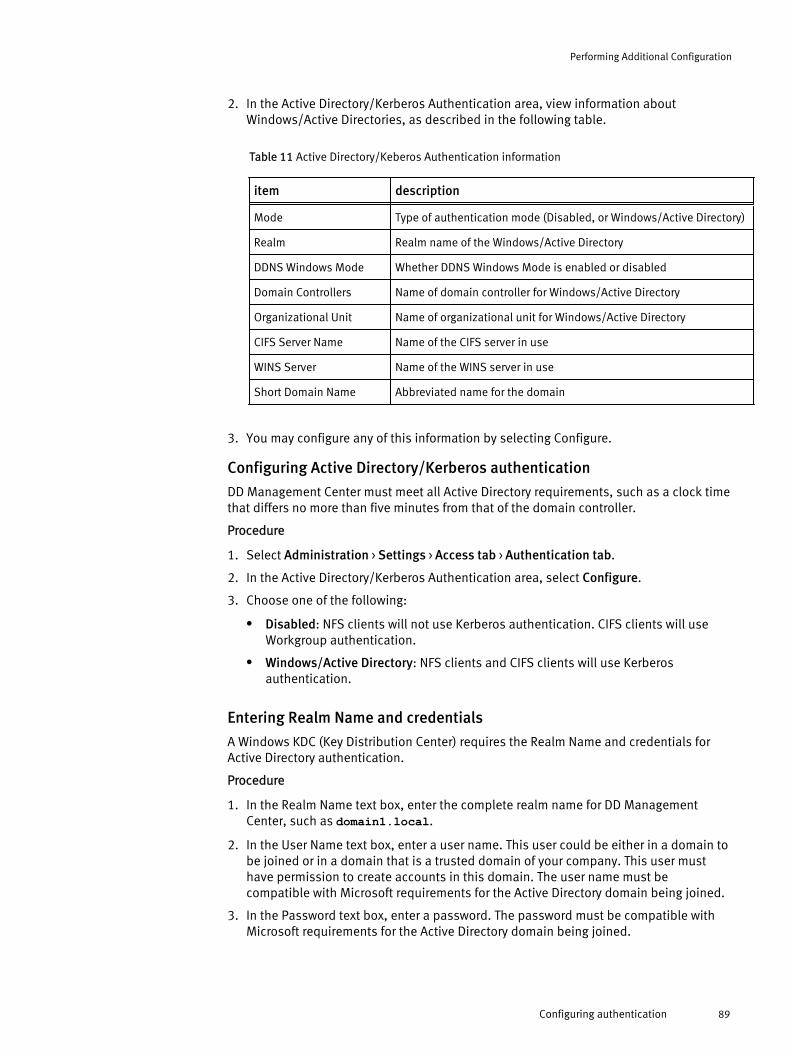
2. In the Active Directory/Kerberos Authentication area, view information aboutWindows/Active Directories, as described in the following table.
Table 11 Active Directory/Keberos Authentication information
item description
Mode Type of authentication mode (Disabled, or Windows/Active Directory)
Realm Realm name of the Windows/Active Directory
DDNS Windows Mode Whether DDNS Windows Mode is enabled or disabled
Domain Controllers Name of domain controller for Windows/Active Directory
Organizational Unit Name of organizational unit for Windows/Active Directory
CIFS Server Name Name of the CIFS server in use
WINS Server Name of the WINS server in use
Short Domain Name Abbreviated name for the domain
3. You may configure any of this information by selecting Configure.
Configuring Active Directory/Kerberos authentication
DD Management Center must meet all Active Directory requirements, such as a clock timethat differs no more than five minutes from that of the domain controller.
Procedure
1. Select Administration > Settings > Access tab > Authentication tab.
2. In the Active Directory/Kerberos Authentication area, select Configure.
3. Choose one of the following:
l Disabled: NFS clients will not use Kerberos authentication. CIFS clients will useWorkgroup authentication.
l Windows/Active Directory: NFS clients and CIFS clients will use Kerberosauthentication.
Entering Realm Name and credentials
A Windows KDC (Key Distribution Center) requires the Realm Name and credentials forActive Directory authentication.
Procedure
1. In the Realm Name text box, enter the complete realm name for DD ManagementCenter, such as domain1.local.
2. In the User Name text box, enter a user name. This user could be either in a domain tobe joined or in a domain that is a trusted domain of your company. This user musthave permission to create accounts in this domain. The user name must becompatible with Microsoft requirements for the Active Directory domain being joined.
3. In the Password text box, enter a password. The password must be compatible withMicrosoft requirements for the Active Directory domain being joined.
Performing Additional Configuration
Configuring authentication 89

Configuring advanced Kerberos settings
You may optionally configure advanced Kerberos settings for CIFS Server Name, DomainControllers, and Organizational Unit.
Procedure
1. For CIFS Server Name:
l Select Use default: xxx to use the default CIFS server name, or
l Select Manual, and enter the CIFS server name in the text box.
2. For Domain Controllers:
l Select Automatically assign, which is the default and recommended method, or
l Select Manual, and enter controller name(s) in the text box(es). Up to threecontroller names can be added. You can enter fully qualified domain names, hostnames, or IP (IPv4 or IPv6) addresses.
3. For Organizational Units:
l Select Use default: xxx to use the default Organization Units, or
l Select Manual, and enter the Organizational Unit name in the text box.
Note
The account is moved to the new Organizational Unit.
4. Select OK.
After you finish
After configuring Windows authentication, you must enable CIFS authentication from theDD Management Center command line:
adminaccess authentication add cifs
Creating Windows groups
A Windows group is a group (based on one of the user roles – admin or user) that existson a Windows domain controller.
Procedure
1. Select Administration > Settings > Access tab > Authentication tab.
2. In the Active Directory/Kerberos Authentication area, select Create to display theCreate Windows Group dialog.
3. Enter the group name in the text box. The domain for the group must be specified. Forexample, domain\group name.
4. Select either admin or user from the Management Role drop-down list.
5. Select OK.
Modifying Windows groups
After you have created a Windows group, you can modify it, as needed.
Procedure
1. Select Administration > Settings > Access tab > Authentication tab.
Performing Additional Configuration
90 EMC Data Domain Management Center 1.3 User Guide

2. In the Active Directory/Kerberos Authentication area, choose a Windows group fromthe list, and select Modify to display the Modify Windows Group dialog.
3. Edit the group name in the text box. The domain for the group must be specified, forexample, domain\group name.
4. Select either admin or user from the Management Role drop-down list.
5. Select OK.
Deleting Windows groups
You cannot delete default Windows groups, such as Domain Admins. If a defaultWindows group is selected, the Delete button will be grayed out.
Procedure
1. Select Administration > Settings > Access tab > Authentication tab.
2. In the Active Directory/Kerberos Authentication area, choose a Windows group fromthe list, and select Delete to display the Delete Windows Group dialog.
3. Select OK.
Configuring Workgroup authenticationWorkgroup mode joins DD Management Center to a workgroup domain.
Procedure
1. Select Administration > Settings > Access tab > Authentication tab.
2. In the Workgroup Authentication area, select Configure to display the WorkgroupAuthentication dialog.
3. For Workgroup Name, select Manual to enter a different Workgroup name in the textbox.
4. For CIFS Server Name, select Manual to enter a different CIFS server name (DD system)in the text box.
5. Select OK.
NIS authenticationLocal user accounts on a DD system start with a UID of 500. When you set up a DD systemin an NIS (network information service) environment, be aware of potential UID conflictsbetween local and NIS user accounts. To avoid such conflicts, during initial planningconsider the size of potential local accounts when you define allowable UID ranges forNIS users.
Procedure
1. Select Administration > Settings > Access tab > Authentication tab.
2. In the NIS Authentication area, view information about NIS Servers and configured NISGroups, as described in the following table.
Table 12 NIS Authentication Information
item description
NIS Status Status of service: enabled or disabled
Domain Name Name of domain for this service
Server Name of server performing authentication
Performing Additional Configuration
Configuring authentication 91
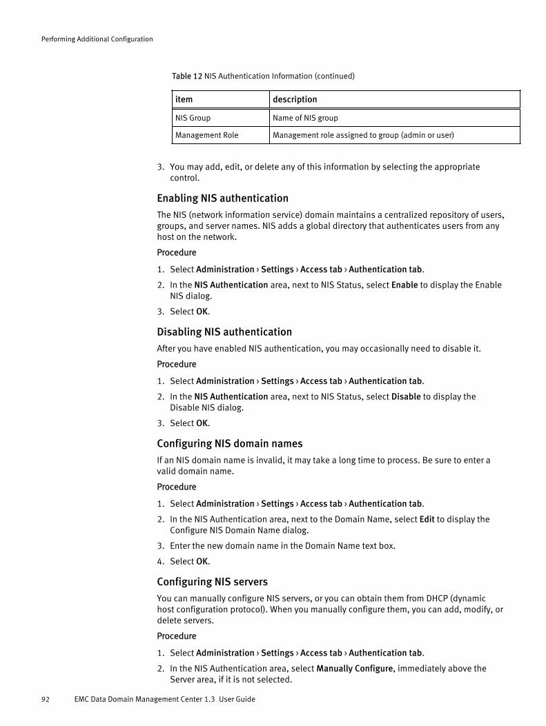
Table 12 NIS Authentication Information (continued)
item description
NIS Group Name of NIS group
Management Role Management role assigned to group (admin or user)
3. You may add, edit, or delete any of this information by selecting the appropriatecontrol.
Enabling NIS authentication
The NIS (network information service) domain maintains a centralized repository of users,groups, and server names. NIS adds a global directory that authenticates users from anyhost on the network.
Procedure
1. Select Administration > Settings > Access tab > Authentication tab.
2. In the NIS Authentication area, next to NIS Status, select Enable to display the EnableNIS dialog.
3. Select OK.
Disabling NIS authentication
After you have enabled NIS authentication, you may occasionally need to disable it.
Procedure
1. Select Administration > Settings > Access tab > Authentication tab.
2. In the NIS Authentication area, next to NIS Status, select Disable to display theDisable NIS dialog.
3. Select OK.
Configuring NIS domain names
If an NIS domain name is invalid, it may take a long time to process. Be sure to enter avalid domain name.
Procedure
1. Select Administration > Settings > Access tab > Authentication tab.
2. In the NIS Authentication area, next to the Domain Name, select Edit to display theConfigure NIS Domain Name dialog.
3. Enter the new domain name in the Domain Name text box.
4. Select OK.
Configuring NIS servers
You can manually configure NIS servers, or you can obtain them from DHCP (dynamichost configuration protocol). When you manually configure them, you can add, modify, ordelete servers.
Procedure
1. Select Administration > Settings > Access tab > Authentication tab.
2. In the NIS Authentication area, select Manually Configure, immediately above theServer area, if it is not selected.
Performing Additional Configuration
92 EMC Data Domain Management Center 1.3 User Guide
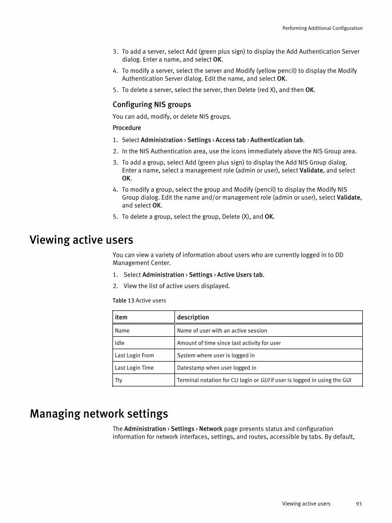
3. To add a server, select Add (green plus sign) to display the Add Authentication Serverdialog. Enter a name, and select OK.
4. To modify a server, select the server and Modify (yellow pencil) to display the ModifyAuthentication Server dialog. Edit the name, and select OK.
5. To delete a server, select the server, then Delete (red X), and then OK.
Configuring NIS groups
You can add, modify, or delete NIS groups.
Procedure
1. Select Administration > Settings > Access tab > Authentication tab.
2. In the NIS Authentication area, use the icons immediately above the NIS Group area.
3. To add a group, select Add (green plus sign) to display the Add NIS Group dialog.Enter a name, select a management role (admin or user), select Validate, and selectOK.
4. To modify a group, select the group and Modify (pencil) to display the Modify NISGroup dialog. Edit the name and/or management role (admin or user), select Validate,and select OK.
5. To delete a group, select the group, Delete (X), and OK.
Viewing active usersYou can view a variety of information about users who are currently logged in to DDManagement Center.
1. Select Administration > Settings > Active Users tab.
2. View the list of active users displayed.
Table 13 Active users
item description
Name Name of user with an active session
Idle Amount of time since last activity for user
Last Login From System where user is logged in
Last Login Time Datestamp when user logged in
Tty Terminal notation for CLI login or GUI if user is logged in using the GUI
Managing network settingsThe Administration > Settings > Network page presents status and configurationinformation for network interfaces, settings, and routes, accessible by tabs. By default,
Performing Additional Configuration
Viewing active users 93

the Interfaces tab initially displays. Use this area to configure networking for the DDManagement Center.
Configuring network interfacesYou can configure physical network connections and create VLANs and IP aliases for DDManagement Center.
Viewing interface informationThe Interfaces page (Administration > Settings > Network tab > Interfaces tab) lets youmanage and configure the physical (Ethernet) interface, DHCP, DDNS, and IP addresses,and displays network information and status.
There are two parts to this page: the Interfaces area and the Interface Details area.
Table 14 Interfaces area
item description
Interface Name of each Ethernet interface associated with DD Management Center.Physical interfaces names start with eth.
Enabled Lets you view or change status of the interface.
l Select Yes to enable interface and connect it to the network.
l Select No to disable interface and disconnect it from the network.
DHCP Indicates whether the interface is configured with an IP address from a DHCP(Dynamic Host Configuration Protocol) server.
IP Address IP address associated with the interface, which is used by the network toidentify the interface. If the interface is configured through DHCP, an asteriskappears after this value.
Netmask Netmask associated with the interface. Uses the standard IP network maskformat. If the interface is configured through DHCP, an asterisk appears afterthis value.
Link Indicates whether the interface currently has a live Ethernet connection.
Additional Info Provides additional settings for the interface, for example, the bonding mode.
To populate the Interface Details area, select an interface.
Table 15 Interface Details area
item description
Interface Name Name of selected interface.
HardwareAddress
MAC address of selected interface, for example,
00:02:b3:b0:8a:d2
Cable Indicates whether interface is Copper.
MTU Maximum Transfer Unit value assigned to interface.
Performing Additional Configuration
94 EMC Data Domain Management Center 1.3 User Guide
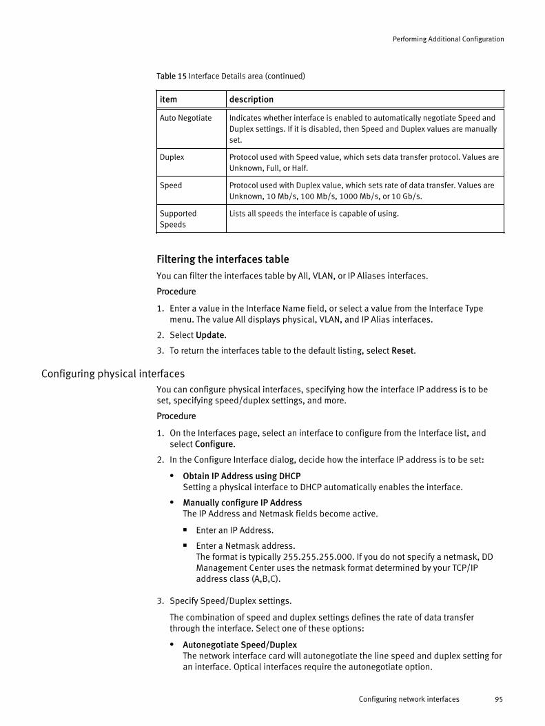
Table 15 Interface Details area (continued)
item description
Auto Negotiate Indicates whether interface is enabled to automatically negotiate Speed andDuplex settings. If it is disabled, then Speed and Duplex values are manuallyset.
Duplex Protocol used with Speed value, which sets data transfer protocol. Values areUnknown, Full, or Half.
Speed Protocol used with Duplex value, which sets rate of data transfer. Values areUnknown, 10 Mb/s, 100 Mb/s, 1000 Mb/s, or 10 Gb/s.
SupportedSpeeds
Lists all speeds the interface is capable of using.
Filtering the interfaces table
You can filter the interfaces table by All, VLAN, or IP Aliases interfaces.
Procedure
1. Enter a value in the Interface Name field, or select a value from the Interface Typemenu. The value All displays physical, VLAN, and IP Alias interfaces.
2. Select Update.
3. To return the interfaces table to the default listing, select Reset.
Configuring physical interfacesYou can configure physical interfaces, specifying how the interface IP address is to beset, specifying speed/duplex settings, and more.
Procedure
1. On the Interfaces page, select an interface to configure from the Interface list, andselect Configure.
2. In the Configure Interface dialog, decide how the interface IP address is to be set:
l Obtain IP Address using DHCPSetting a physical interface to DHCP automatically enables the interface.
l Manually configure IP AddressThe IP Address and Netmask fields become active.
n Enter an IP Address.
n Enter a Netmask address.The format is typically 255.255.255.000. If you do not specify a netmask, DDManagement Center uses the netmask format determined by your TCP/IPaddress class (A,B,C).
3. Specify Speed/Duplex settings.
The combination of speed and duplex settings defines the rate of data transferthrough the interface. Select one of these options:
l Autonegotiate Speed/DuplexThe network interface card will autonegotiate the line speed and duplex setting foran interface. Optical interfaces require the autonegotiate option.
Performing Additional Configuration
Configuring network interfaces 95
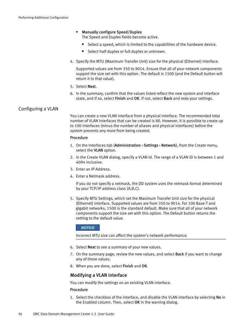
l Manually configure Speed/DuplexThe Speed and Duplex fields become active.
n Select a speed, which is limited to the capabilities of the hardware device.
n Select half-duplex or full-duplex or unknown.
4. Specify the MTU (Maximum Transfer Unit) size for the physical (Ethernet) interface.
Supported values are from 350 to 9014. Ensure that all of your network componentssupport the size set with this option. The default is 1500 (and the Default button willreturn it to that value).
5. Select Next.
6. In the summary, confirm that the values listed reflect the new system and interfacestate, and if so, select Finish and OK. If not, select Back and redo your settings.
Configuring a VLANYou can create a new VLAN interface from a physical interface. The recommended totalnumber of VLAN interfaces that can be created is 80. However, it is possible to create upto 100 interfaces (minus the number of aliases and physical interfaces) before thesystem prevents any more from being created.
Procedure
1. On the Interfaces tab (Administration > Settings > Network), from the Create menu,select the VLAN option.
2. In the Create VLAN dialog, specify a VLAN Id. The range of a VLAN ID is between 1 and4094 inclusive.
3. Enter an IP Address.
4. Enter a Netmask address.
If you do not specify a netmask, the DD system uses the netmask format determinedby your TCP/IP address class (A,B,C).
5. Specify MTU Settings, which set the Maximum Transfer Unit size for the physical(Ethernet) interface. Supported values are from 350 to 9014. For 100 Base-T andgigabit networks, 1500 is the standard default. Make sure that all of your networkcomponents support the size set with this option. The Default button returns thesetting to the default value.
NOTICE
Incorrect MTU size can affect the system’s network performance.
6. Select Next to see a summary of your new values.
7. On the summary page, review the new values, and select Back if you want to changeany of these values.
8. When you are done, select Finish and OK.
Modifying a VLAN interface
You can modify the settings on an existing VLAN interface.
Procedure
1. Select the checkbox of the interface, and disable the VLAN interface by selecting No inthe Enabled column. Then, select OK in the warning dialog.
Performing Additional Configuration
96 EMC Data Domain Management Center 1.3 User Guide
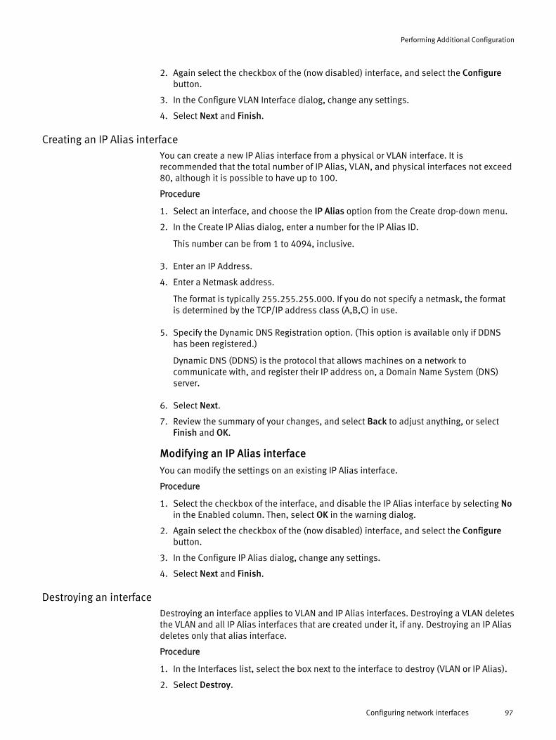
2. Again select the checkbox of the (now disabled) interface, and select the Configurebutton.
3. In the Configure VLAN Interface dialog, change any settings.
4. Select Next and Finish.
Creating an IP Alias interfaceYou can create a new IP Alias interface from a physical or VLAN interface. It isrecommended that the total number of IP Alias, VLAN, and physical interfaces not exceed80, although it is possible to have up to 100.
Procedure
1. Select an interface, and choose the IP Alias option from the Create drop-down menu.
2. In the Create IP Alias dialog, enter a number for the IP Alias ID.
This number can be from 1 to 4094, inclusive.
3. Enter an IP Address.
4. Enter a Netmask address.
The format is typically 255.255.255.000. If you do not specify a netmask, the formatis determined by the TCP/IP address class (A,B,C) in use.
5. Specify the Dynamic DNS Registration option. (This option is available only if DDNShas been registered.)
Dynamic DNS (DDNS) is the protocol that allows machines on a network tocommunicate with, and register their IP address on, a Domain Name System (DNS)server.
6. Select Next.
7. Review the summary of your changes, and select Back to adjust anything, or selectFinish and OK.
Modifying an IP Alias interface
You can modify the settings on an existing IP Alias interface.
Procedure
1. Select the checkbox of the interface, and disable the IP Alias interface by selecting Noin the Enabled column. Then, select OK in the warning dialog.
2. Again select the checkbox of the (now disabled) interface, and select the Configurebutton.
3. In the Configure IP Alias dialog, change any settings.
4. Select Next and Finish.
Destroying an interfaceDestroying an interface applies to VLAN and IP Alias interfaces. Destroying a VLAN deletesthe VLAN and all IP Alias interfaces that are created under it, if any. Destroying an IP Aliasdeletes only that alias interface.
Procedure
1. In the Interfaces list, select the box next to the interface to destroy (VLAN or IP Alias).
2. Select Destroy.
Performing Additional Configuration
Configuring network interfaces 97

3. In the Confirm Destroy dialog, select OK.
Viewing an interface hierarchyYou can view an interface hierarchy using the Tree View dialog.
Procedure
1. On the Interfaces tab, select Tree View.
2. In the Tree View dialog, select the plus or minus boxes to expand or contract the treeview, which shows the hierarchy.
3. Select Close to exit the Tree View.
Configuring network settingsYou can use the Settings tab on the Network page to view and configure network settings.
Viewing network settingsYou can view network settings for DD Management Center, while also adding or removingsettings.
Procedure
1. Select Administration > Settings > Network tab > Settings tab.
2. View the network settings (described in the following table), and add or removesettings using the Edit button.
Table 16 Network settings
item description
Host Settings
Host Name Host name of selected DD system
Domain Name Fully qualified domain name associated with selected DD system
Search Domain List
Search Domain List of search domains used by DD system. The DD system applies the searchdomain as a suffix to the host name.
Hosts Mapping
IP Address IP address of host to resolve
Host Name Host names associated with IP address
DNS List
DNS IP Address Current DNS IP addresses associated with selected DD system. An asterisk (*)means the IP addresses were assigned through DHCP.
Setting host namesBoth the host name and domain name are used by other systems when they want toaccess DD Management Center. The host name can be set manually or automaticallygenerated with DHCP.
Note the following before setting a host or domain name:
Performing Additional Configuration
98 EMC Data Domain Management Center 1.3 User Guide

l Do not include an underscore in the host name. It is incompatible with somebrowsers.
l Changing the names of an active host can cause: (1) a break in the currentconnection – if this happens, log back in, and check the saved settings, and/or (2)disruption of communication with managed DD systems.
Procedure
1. Select Administration > Settings > Network tab > Settings tab.
2. In the Host Settings area, select Edit.
3. In the Configure Host dialog, select how you want to set the host and domain names:
l Obtain Settings using DHCP.
l Manually configure host..
n Enter a host name.
n Enter a domain name, which is the domain name associated with DDManagement Center. Typically, this is your company domain name. Forexample, yourcompany.com
4. Select OK.
Managing a domain search listYou can add or remove a domain from a domain search list.
Adding a search domain
You can add a seatch domain using the Configure Search Domains dialog.
Procedure
1. Select Edit in the Search Domain List area.
2. In the Configure Search Domains dialog, select the add ( + ) button.
a. In the Add Search Domain dialog, enter a name in the Search Domain text box.
b. Select OK.
3. Select OK.
Results
Changes are applied to the system. The system returns you to the Settings view.
Removing a search domain
You can remove a search domain using the Configure Search Domains dialog.
Procedure
1. Select Edit in the Search Domain List area.
a. In the Configure Search Domains dialog, select the search domain to remove.
b. Select the remove (X) button.
2. Select OK.
Results
Changes are applied to the system. The system returns you to the Settings tab.
Performing Additional Configuration
Configuring network settings 99

Mapping hostsUse the Hosts Mapping area to add a mapping that ties an IP address to a host name.
Adding a host name mapping
You can add a host name mapping, while adding a new host name, if necessary.
Procedure
1. Select Add in the Hosts Mapping area to create a host mapping.
2. If no hosts are listed in the Host Name list, select the add (+) button.
3. In the Add Host dialog, enter a host name that will be used for the mapping in theHost Name box.
4. Select OK.
The new host name is added to the list of Host Names. Continue to add host names asnecessary.
5. In the Add Hosts dialog, enter the IP address that will be mapped to a host, thenselect the checkboxes of one or more host names from the list of hosts.
6. Select OK.
The mapping is created, and you are returned to the Settings tab.
Deleting a host name mapping
You can delete a host name mapping using the Delete Host dialog.
Procedure
1. In the Settings view, select the checkbox of the host mapping to delete in the HostsMapping area.
2. Select Delete in the Hosts Mapping area.
The Delete Host dialog appears.
3. Select Delete.
Confirmation messages are displayed.
4. Select Close when the Completed message appears.
You are returned to the Settings tab.
Managing DNS IP addressesYou can add or remove a DNS IP address.
Adding a DNS IP address
You can add a DNS IP address.
Procedure
1. Select Edit in the DNS List area.
2. In the Configure DNS dialog, determine the method for obtaining the DNS. Choose toeither:
l Obtain DNS Settings using DHCP. (At least one interface must be configured usingDHCP.)
Performing Additional Configuration
100 EMC Data Domain Management Center 1.3 User Guide

l Manually configure DNS:
n Select the plus (+) button.
n Enter the DNS IP address.
n Select OK.
Deleting a DNS IP address
You can delete a DNS IP address.
Procedure
1. Select the Manually configure DNS radio button.
2. Select the checkbox of the DNS IP address to delete.
3. Select the delete (X) button.
4. Select OK.
Configuring routesRoutes determine the path taken to transfer data to and from the local host (DDManagement Center) to another network or host.
DD Management Center does not generate or respond to any of the network routingmanagement protocols (RIP, EGRP/EIGRP, and BGP). The only routing implemented on DDManagement Center is based on the internal route table, where the administrator maydefine a specific network or subnet used by a physical interface (or interface group).
DD Management Center uses source-based routing, which means outbound networkpackets that match the subnet of multiple interfaces will be routed over the physicalinterface from which they originated.
Note
The routing for connections initiated from DD Management Center (such as forreplication) depend on the source address used for interfaces using the same subnet. Toforce traffic for a specific interface to a specific destination (even if that interface is on thesame subnet as other interfaces), you can configure a static routing entry between twosystems that will override source routing.
Viewing route informationThe Routes pages provides details about all of the routing information for your DDManagement Center setup, including the default gateway values, and static and dynamicroutes.
Procedure
1. Select Administration > Settings > Network tab > Routes tab.
2. On the Routes page, view the configured static and dynamic routes (described in thefollowing table), and create or modify routing information.
Table 17 Route information
item description
Default IPv4Gateway
Address of the default IPv4 gateway.
Performing Additional Configuration
Configuring routes 101

Table 17 Route information (continued)
item description
Default IPv6Gateway
Address of the default IPv6 gateway.
Static Routes Static routes that are either network or host-based routes.
Route Spec Route specification being used to configure routes.
Dynamic Routes Dynamically assigned routes that use network or host paths for datatransmission.
Destination Destination host/network where the network traffic (data) is sent.
Gateway Address of the router in the DD Management Center network or 0.0.0.0 ifno gateway is set.
Genmask Netmask for the destination net. Initially set to 255.255.255.255 for a hostdestination and 0.0.0.0 for the default route.
Flags Possible values include:
U – Route is up.
H – Target is a host.
G – Use gateway.
R – Reinstate route for dynamic routing.
D – Dynamically installed by daemon or redirect.
M – Modified from routing daemon or redirect.
A – Installed by addrconf.
C – Cache entry.
! – Reject route.
Metric Distance to target (usually counted in hops). (It is not used by the DD OS,but might be needed by routing daemons.)
MTU Maximum Transfer Unit (MTU) size for physical (Ethernet) interface.
Window Default window size for TCP connections over this route.
IRTT Initial RTT (Round Trip Time). The kernel uses this to estimate the best TCPprotocol parameters without waiting on (possibly slow) answers.
Interface Interface name associated with routing interface.
Setting the default IPv4 or IPv6 gateway addressYou can set the default IPv4 or IPv6 gateway address by using the DHCP server or bymanually configuring it.
Procedure
1. Select Edit next to either the Default IPv4 Gateway or the Default IPv6 Gateway.
2. In the Configure Default IPv4/IPv6 Gateway dialog, choose how the gateway addressis to be set:
l Use DHCP valueIndicates that you want to use the DHCP (Dynamic Host Configuration Protocol)server value.
Performing Additional Configuration
102 EMC Data Domain Management Center 1.3 User Guide

l Manually ConfigureIndicates that you want to manually configure the gateway address and enablesthe Gateway box, into which you should enter the gateway address.
3. Select OK.
The system processes the information and returns you to the Routes tab.
Creating static routesTo force traffic for a specific interface to a specific destination (even if that interface is onthe same subnet as other interfaces), you can configure a static routing entry betweentwo systems that will override source routing.
Procedure
1. Select Create in the Static Routes area.
2. In the Create Routes dialog, select an interface, and select Next.
3. Specify the Destination by selecting one of the following:
l Network – Enter the network IP address and netmask.
Note
This is not the IP address of the interface. The interface was selected in the initialdialog, and it is used for routing traffic.
l Host – Enter the host name or IP address of the destination host of the route.
4. Optionally, enter a new gateway address in the Gateway box.
5. Select Next.
6. Review your changes on the Summary page, and select Finish.
Progress messages are displayed. When the changes are applied, the messageindicates Completed.
7. Select OK to close the dialog.
The new route specification is listed in the Route Spec list under Static Routes.
Deleting static routesYou can delete static routes when you no longer need them.
Procedure
1. In the Route Spec area, select the checkbox of the route specification to delete.
2. Select Delete.
The Delete Route dialog appears.
3. Select Delete and Close.
The selected route specification is removed from the Route Spec list.
Performing Additional Configuration
Configuring routes 103

Upgrading DD Management Center softwareOnly DD Management Center admins have permission to manage software upgradepackages and perform upgrades for DD Management Center.
Upgrading DD Management Center software is done in two stages:
l Obtaining an image from EMC Online Support, or selecting a previously obtainedupgrade image that has been saved.
l Performing the upgrade on the DD Management Center.
Managing DD Management Center upgrade packagesYou can download an upgrade image from EMC Online Support to a locally accessibledrive and then add it to the upgrade package collection managed by DD ManagementCenter.
Procedure
1. Select Administration > Settings > Upgrade tab.
2. In the Upgrade Packages Available on Data Domain System area, view the availableupgrade packages, their sizes, and their modification dates. Then, select one of thefollowing options:
l To get a new upgrade package to store locally, select the EMC Online Support link.
l To upload a package that has been stored locally to the inventory, select UploadUpgrade Package, and browse to the local drive to select the package.
l To delete a package, select the package from the inventory list, and select RemoveUpgrade Package.
3. To perform the upgrade, see the procedure in the following section.
Performing a DD Management Center software upgradeAfter you have uploaded an upgrade package, you can use it to upgrade your DDManagement Center software.
Note
Software upgrade files use the .rpm file extension. This topic assumes that you areupdating only DD Management Center. If you make hardware changes, such as adding,swapping, or moving interface cards, you must update the DD OS configuration tocorrespond with the hardware changes.
Procedure
1. Review the appropriate DD Management Center Release Notes for instructions for thisupgrade, and verifying available space.
Note
For most releases, upgrades are permitted from up to two prior major releaseversions.
2. Select Administration > Settings > Upgrade tab.
Performing Additional Configuration
104 EMC Data Domain Management Center 1.3 User Guide

3. In the Upgrade Packages Available on Data Domain System area, select the upgradepackage from the list, and select Perform System Upgrade.
4. Monitor the upgrade progress from the DD Management Center console page.
5. Be aware that the upgrade process automatically reboots DD Management Center.
6. It is recommended that you keep the System Upgrade progress dialog open until theupgrade completes, or until the system powers off.
Checking a DD Management Center serial numberEach DD Management Center virtual machine has a unique serial number, which is usedto identify the system in autosupport messages.
1. Select Administration > Settings > Serial Number tab.
2. View the serial number listed.
3. To change the serial number, select Edit.
4. In the Edit dialog, enter the new serial number, and select Submit.
Note
DD Management Center does not require a license, but the managed DD systems musthave licenses for their core and optional features.
Managing alertsYou can configure settings to determine who will receive DD Management Center alertnotifications and daily alert summaries.
DD Management Center and DD systems (DD OS) use the same alert system. Detailedinformation about the alert system is described in the EMC Data Domain Operating SystemAdministration Guide.
Managing alert notificationsThe groups that are configured to receive DD Management Center alert notifications arelisted in the Administration > Settings > Alerts page with the Notification tab. Selecting agroup in the table populates the Details panels for alert class attributes and subscriberswho receive notification when alerts reach the severity that is configured for the alertclass.
Filtering the notifications listTo filter (or search for an item) in the notifications group list, type a group name and/orsubscriber email in the appropriate text box in the Filter By area. Then select Update. Theresult is displayed at the top of the notification list. Select Reset to return the group list tothe default order.
Creating a notification groupBy default, all alerts are sent to the [email protected] group, but additional groups can be created to receive specific classes of alertnotifications.
Procedure
1. Select Administration > Settings > Alerts tab > Notifications tab > Add.
Performing Additional Configuration
Checking a DD Management Center serial number 105

2. In the Add Group dialog, type a name for the group in the Group Name text box.
3. Select the alert class attributes, set the severity level at which notifications are to besent, and select OK.
For example, you could create a CriticalWarnings group, select all classes, and set theseverity level to Critical.
4. Select the checkbox of the group, now in the Notifications group list, and selectModify.
5. In the Modify Group dialog, select Subscribers, and in the Subscribers panel, selectAdd (green plus sign), add the email address of a subscriber, and select OK.
6. Repeat this step for each subscriber who needs to be added to the group, and selectFinish.
Verifying subscriber emails in a notification group
You can send a test email to subscribers in a notification group to verify that the emailaddresses are operational.
Procedure
1. In the More Tasks menu, select Send Test Alert.
2. In the Notification Groups panel, select the checkboxes of the groups to receive thetest email, then select Next.
3. In the Additional Email Addresses panel, add or modify email addresses, if necessary.
4. Select Send Now.
Modifying a notification groupYou can modify several aspects of a notification group.
Procedure
1. Select the checkbox of the group in the Notifications group table, and select Modify.
2. In the Modify Group dialog, select Group Properties, and in the Class Attributes area,add or remove classes, change any severity levels, and select Next.
3. The Subscribers area displays. Add or remove any subscriber email addresses, asneeded, and select Finish.
Deleting a notification groupYou can delete any notification group, except the Default notification group.
Procedure
1. Select one or more checkboxes of groups in the Notifications group table, and selectDelete.
2. In the Delete Group dialog, verify the deletion, and select OK.
3. Select OK to exit the confirmation dialog.
Resetting a notification groupYou can remove all notification groups that were added and remove any changes to theDefault group.
Procedure
1. From the More Tasks menu, select Reset Notification Groups.
Performing Additional Configuration
106 EMC Data Domain Management Center 1.3 User Guide
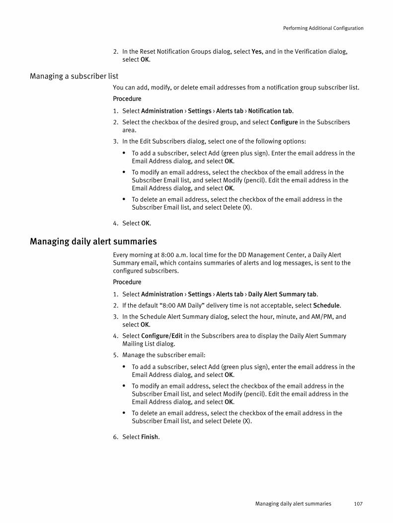
2. In the Reset Notification Groups dialog, select Yes, and in the Verification dialog,select OK.
Managing a subscriber listYou can add, modify, or delete email addresses from a notification group subscriber list.
Procedure
1. Select Administration > Settings > Alerts tab > Notification tab.
2. Select the checkbox of the desired group, and select Configure in the Subscribersarea.
3. In the Edit Subscribers dialog, select one of the following options:
l To add a subscriber, select Add (green plus sign). Enter the email address in theEmail Address dialog, and select OK.
l To modify an email address, select the checkbox of the email address in theSubscriber Email list, and select Modify (pencil). Edit the email address in theEmail Address dialog, and select OK.
l To delete an email address, select the checkbox of the email address in theSubscriber Email list, and select Delete (X).
4. Select OK.
Managing daily alert summariesEvery morning at 8:00 a.m. local time for the DD Management Center, a Daily AlertSummary email, which contains summaries of alerts and log messages, is sent to theconfigured subscribers.
Procedure
1. Select Administration > Settings > Alerts tab > Daily Alert Summary tab.
2. If the default “8:00 AM Daily” delivery time is not acceptable, select Schedule.
3. In the Schedule Alert Summary dialog, select the hour, minute, and AM/PM, andselect OK.
4. Select Configure/Edit in the Subscribers area to display the Daily Alert SummaryMailing List dialog.
5. Manage the subscriber email:
l To add a subscriber, select Add (green plus sign), enter the email address in theEmail Address dialog, and select OK.
l To modify an email address, select the checkbox of the email address in theSubscriber Email list, and select Modify (pencil). Edit the email address in theEmail Address dialog, and select OK.
l To delete an email address, select the checkbox of the email address in theSubscriber Email list, and select Delete (X).
6. Select Finish.
Performing Additional Configuration
Managing daily alert summaries 107
Managing general configuration settingsUnder the Administration > SettingsGeneral tab, you can manage settings for your mailserver, how time and date are obtained, some system properties (location and defaultadministrator's email and host name), and SNMP properties.
Configuring mail server settingsYou can set or change the name of your mail server using the Set Mail Server dialog.
Procedure
1. Select Administration > Settings > General tab > Mail Server tab > More Tasks > Set MailServer.
2. In the Set Mail Server dialog, enter the name of the mail server, and select OK.
Configuring time and date settingsYou can set or change the settings for your time zone, as well as how the timing for yoursystem is synchronized [not synchronized or with NTP (Network Time Protocol)], using theConfigure Time Settings dialog.
Procedure
1. Select Administration > SettingsGeneral tab > Time and Date Settings tab > More Tasks> Configure Time Settings.
2. In the Configure Time Settings dialog, select the Time Zone drop-down list, and selectthe time zone where DD Management Center resides.
3. Set how time is synchronized:
l To manually set the time and date, select None, enter the date in the text box, anduse the drop-down lists to set the time.
l To use NTP to synchronize the time, select NTP, and choose how to access the NTPserver:
n Obtain NTP Servers using DHCP – DHCP (Dynamic Host Configuration Protocol)will automatically select a server.
n Manually Configure – Add the IP address of the server in the NTP Servers area.
4. Select OK.
Configuring system propertiesYou can provide an admin email address to be added to the alert and autosupportnotification lists, and an admin host to be added to the FTP and Telnet access lists, usingthe Set System Properties dialog.
Procedure
1. Select Administration > Settings > General tab > System Properties tab > More Tasks >Set System Properties.
2. In the Set System Properties dialog, the Location text field shows where the system islocated. [This text field is not used by DD Management Center (or DD OS); it is heresimply for your information.]
3. In the Admin Email text box, enter an email address to be automatically added to thealert and autosupport notification lists.
Performing Additional Configuration
108 EMC Data Domain Management Center 1.3 User Guide
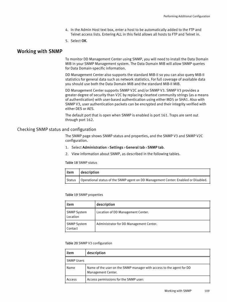
4. In the Admin Host text box, enter a host to be automatically added to the FTP andTelnet access lists. Entering ALL in this field allows all hosts to FTP and Telnet in.
5. Select OK.
Working with SNMPTo monitor DD Management Center using SNMP, you will need to install the Data DomainMIB in your SNMP Management system. The Data Domain MIB will allow SNMP queriesfor Data Domain-specific information.
DD Management Center also supports the standard MIB-II so you can also query MIB-IIstatistics for general data such as network statistics. For full coverage of available datayou should use both the Data Domain MIB and the standard MIB-II MIB.
DD Management Center supports SNMP V2C and/or SNMP V3. SNMP V3 provides agreater degree of security than V2C by replacing cleartext community strings (as a meansof authentication) with user-based authentication using either MD5 or SHA1. Also withSNMP V3, user authentication packets can be encrypted and their integrity verified witheither DES or AES.
The default port that is open when SNMP is enabled is port 161. Traps are sent outthrough port 162.
Checking SNMP status and configurationThe SNMP page shows SNMP status and properties, and the SNMP V3 and SNMP V2Cconfiguration.
1. Select Administration > Settings > General tab > SNMP tab.
2. View information about SNMP, as described in the following tables.
Table 18 SNMP status
item description
Status Operational status of the SNMP agent on DD Management Center: Enabled or Disabled.
Table 19 SNMP properties
item description
SNMP SystemLocation
Location of DD Management Center.
SNMP SystemContact
Administrator for DD Management Center.
Table 20 SNMP V3 configuration
item description
SNMP Users
Name Name of the user on the SNMP manager with access to the agent for DDManagement Center.
Access Access permissions for the SNMP user:
Performing Additional Configuration
Working with SNMP 109
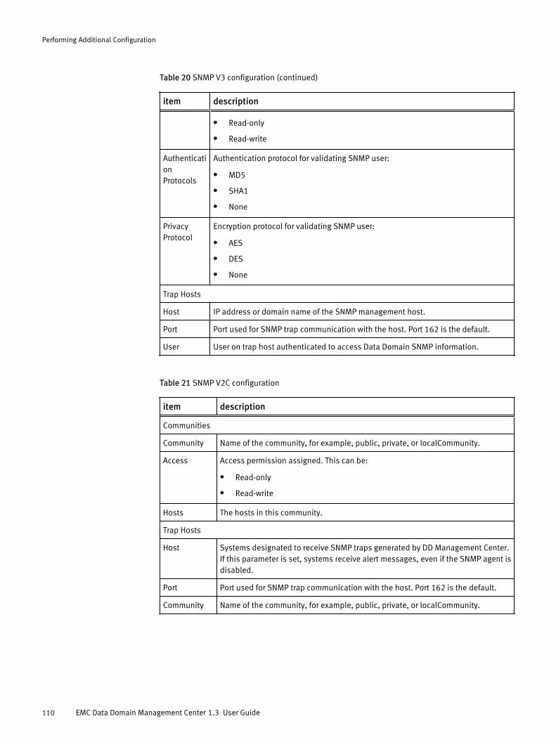
Table 20 SNMP V3 configuration (continued)
item description
l Read-only
l Read-write
AuthenticationProtocols
Authentication protocol for validating SNMP user:
l MD5
l SHA1
l None
PrivacyProtocol
Encryption protocol for validating SNMP user:
l AES
l DES
l None
Trap Hosts
Host IP address or domain name of the SNMP management host.
Port Port used for SNMP trap communication with the host. Port 162 is the default.
User User on trap host authenticated to access Data Domain SNMP information.
Table 21 SNMP V2C configuration
item description
Communities
Community Name of the community, for example, public, private, or localCommunity.
Access Access permission assigned. This can be:
l Read-only
l Read-write
Hosts The hosts in this community.
Trap Hosts
Host Systems designated to receive SNMP traps generated by DD Management Center.If this parameter is set, systems receive alert messages, even if the SNMP agent isdisabled.
Port Port used for SNMP trap communication with the host. Port 162 is the default.
Community Name of the community, for example, public, private, or localCommunity.
Performing Additional Configuration
110 EMC Data Domain Management Center 1.3 User Guide

Enabling or disabling SNMPYou can enable or disable SNMP through DD Management Center.
Procedure
1. In the Status area, select Enable to use SNMP.
2. In the Status area, select Disable to stop using SNMP.
Downloading the SNMP MIBYou can download the SNMP MIP through DD Management Center.
Procedure
1. In the Status area, select Download MIB file.
2. In the Opening DATA_DOMAIN.mib dialog, select Save.
Configuring SNMP propertiesYou can configure SNMP system location and system contacts.
Procedure
1. In the SNMP Properties area, select Configure.
2. In the SNMP Configuration dialog, in the text fields, add an SNMP system location (adescription of where DD Management Center is located) and/or an SNMP systemcontact (for example, the email address of the system administrator for DDManagement Center).
3. Select OK.
Managing SNMP V3 usersProcedures for managing V3 users including creating, modifying, and removing useraccounts. Users on the SNMP manager have access to the agent for DD ManagementCenter.
Creating SNMP V3 users
You can set up SNMP V3 users using the Create SNMP User dialog.
Procedure
1. In the SNMP Users area, select Create.
The Create SNMP User dialog appears.
2. In the Name text field, enter the name of the user or the SNMP manager who will haveaccess to the agent for DD Management Center. The name must be a minimum of 8characters.
3. Select either read-only or read-write access for this user.
4. To authenticate the user, select the checkbox for Authentication.
a. Select either the MD5 or the SHA1 protocol.
b. Enter the authentication key in the Key text field.
c. To provide encryption to the authentication session, select the checkbox next toPrivacy.
d. Select either the AES or the DES protocol.
Performing Additional Configuration
Working with SNMP 111
e. Enter the encryption key in the Key text field.
5. Select OK.
The newly added user account appears in the SNMP Users table.
Modifying SNMP V3 users
You can modify a variety of information about SNMP V3 users.
Procedure
1. In the SNMP Users area, select a checkbox for the user, and select Modify.
In the Modify SNMP User dialog, add or change any of the settings.
2. Select either read-only or read-write access for this user.
3. To authenticate the user, select the checkbox for Authentication.
a. Select either the MD5 or the SHA1 protocol.
b. Enter the authentication key in the Key text field.
c. To provide encryption to the authentication session, select the checkbox next toPrivacy.
d. Select either the AES or the DES protocol.
e. Enter the encryption key in the Key text field.
4. Select OK.
The new settings for this user account are displayed in the SNMP Users table.
Removing SNMP V3 users
If an SNMP V3 user is being used by one or more trap hosts, you must first delete the traphosts before deleting the user.
Procedure
1. In the SNMP Users area, select a checkbox for the user, and select Delete.
The Delete SNMP Users dialog box appears.
2. Verify the user name to be deleted, and select OK.
Note
If the Delete button is disabled, the selected user is being used by one or more traphosts. Delete the trap hosts, and then delete the user.
3. In the Delete SNMP User Status dialog box, select Close.
The user account is removed from the SNMP Users table.
Performing Additional Configuration
112 EMC Data Domain Management Center 1.3 User Guide
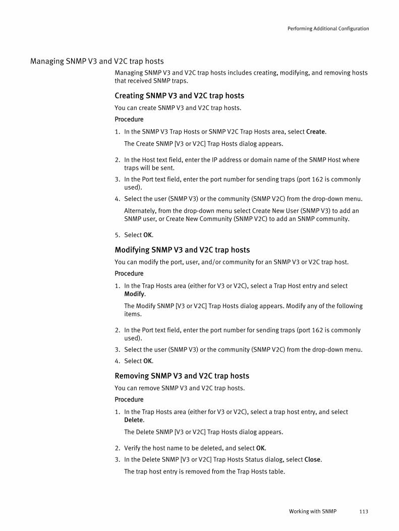
Managing SNMP V3 and V2C trap hostsManaging SNMP V3 and V2C trap hosts includes creating, modifying, and removing hoststhat received SNMP traps.
Creating SNMP V3 and V2C trap hosts
You can create SNMP V3 and V2C trap hosts.
Procedure
1. In the SNMP V3 Trap Hosts or SNMP V2C Trap Hosts area, select Create.
The Create SNMP [V3 or V2C] Trap Hosts dialog appears.
2. In the Host text field, enter the IP address or domain name of the SNMP Host wheretraps will be sent.
3. In the Port text field, enter the port number for sending traps (port 162 is commonlyused).
4. Select the user (SNMP V3) or the community (SNMP V2C) from the drop-down menu.
Alternately, from the drop-down menu select Create New User (SNMP V3) to add anSNMP user, or Create New Community (SNMP V2C) to add an SNMP community.
5. Select OK.
Modifying SNMP V3 and V2C trap hosts
You can modify the port, user, and/or community for an SNMP V3 or V2C trap host.
Procedure
1. In the Trap Hosts area (either for V3 or V2C), select a Trap Host entry and selectModify.
The Modify SNMP [V3 or V2C] Trap Hosts dialog appears. Modify any of the followingitems.
2. In the Port text field, enter the port number for sending traps (port 162 is commonlyused).
3. Select the user (SNMP V3) or the community (SNMP V2C) from the drop-down menu.
4. Select OK.
Removing SNMP V3 and V2C trap hosts
You can remove SNMP V3 and V2C trap hosts.
Procedure
1. In the Trap Hosts area (either for V3 or V2C), select a trap host entry, and selectDelete.
The Delete SNMP [V3 or V2C] Trap Hosts dialog appears.
2. Verify the host name to be deleted, and select OK.
3. In the Delete SNMP [V3 or V2C] Trap Hosts Status dialog, select Close.
The trap host entry is removed from the Trap Hosts table.
Performing Additional Configuration
Working with SNMP 113

Managing SNMP V2C communitiesThe Community string is a sent in cleartext and is very easy to intercept. If this occurs, theinterceptor can retrieve information from devices on your network, modify theirconfiguration, and possibly shut them down. Instead, using the SNMP V3 Usersconfiguration provides authentication and encryption to avoid this.
Creating SNMP V2C communities
You can create SNMP V2C communities.
Procedure
1. In the Communities area, select Create.
The Create SNMP V2C Community dialog appears.
2. In the Community text field, enter the community name of the SNMP manager who willhave access to the agent for DD Management Center. The community name must be aminimum of 8 characters.
3. Select either read-only or read-write access for this community.
4. In the Hosts area, select the checkbox of a host in the list, or:
a. Select + to add a host.
The Host dialog appears.
b. In the Host text field, enter the IP address or domain name of the host.
c. Select OK.
The Host is added to the host list.
5. Select OK.
The new community entry appears in the Communities table.
Modifying SNMP V2C communities
You can modify SNMP V2C communities.
Procedure
1. In the Communities area, select a checkbox for the community, and select Modify.
The Modify SNMP V2C Community dialog appears. Add or change any of the followingsettings.
2. Select either read-only or read-write access for this community.
3. In the Hosts area, select the checkbox of a new host in the list, or:
a. Select + to add a host.
The Host dialog appears.
b. In the Host text field, enter the IP address or domain name of the host.
c. Select OK.
The Host is added to the host list.
4. Select OK.
The modified community entry appears in the Communities table.
Performing Additional Configuration
114 EMC Data Domain Management Center 1.3 User Guide
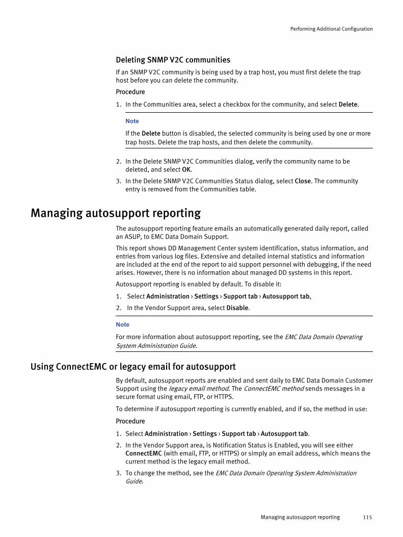
Deleting SNMP V2C communities
If an SNMP V2C community is being used by a trap host, you must first delete the traphost before you can delete the community.
Procedure
1. In the Communities area, select a checkbox for the community, and select Delete.
Note
If the Delete button is disabled, the selected community is being used by one or moretrap hosts. Delete the trap hosts, and then delete the community.
2. In the Delete SNMP V2C Communities dialog, verify the community name to bedeleted, and select OK.
3. In the Delete SNMP V2C Communities Status dialog, select Close. The communityentry is removed from the Communities table.
Managing autosupport reportingThe autosupport reporting feature emails an automatically generated daily report, calledan ASUP, to EMC Data Domain Support.
This report shows DD Management Center system identification, status information, andentries from various log files. Extensive and detailed internal statistics and informationare included at the end of the report to aid support personnel with debugging, if the needarises. However, there is no information about managed DD systems in this report.
Autosupport reporting is enabled by default. To disable it:
1. Select Administration > Settings > Support tab > Autosupport tab,
2. In the Vendor Support area, select Disable.
Note
For more information about autosupport reporting, see the EMC Data Domain OperatingSystem Administration Guide.
Using ConnectEMC or legacy email for autosupportBy default, autosupport reports are enabled and sent daily to EMC Data Domain CustomerSupport using the legacy email method. The ConnectEMC method sends messages in asecure format using email, FTP, or HTTPS.
To determine if autosupport reporting is currently enabled, and if so, the method in use:
Procedure
1. Select Administration > Settings > Support tab > Autosupport tab.
2. In the Vendor Support area, is Notification Status is Enabled, you will see eitherConnectEMC (with email, FTP, or HTTPS) or simply an email address, which means thecurrent method is the legacy email method.
3. To change the method, see the EMC Data Domain Operating System AdministrationGuide.
Performing Additional Configuration
Managing autosupport reporting 115

Adding to the autosupport report email listBy default, autosupport reports are enabled and sent daily to EMC Data Domain CustomerSupport. You may want to add additional email addresses as recipients of autosupportreports.
Procedure
1. Select Administration > Settings > Support tab > Autosupport tab.
2. In the Autosupport Mailing List area, select Configure.
3. In the Configure Autosupport Subscribers dialog, select Add (green + sign) to open theEmail dialog.
4. Enter a recipient’s email address in the text box, and select OK.
5. Select OK to exit the Configure Autosupport Subscribers dialog.
Reviewing generated autosupport reportsThe Autosupport Reports panel contains a list of links to current autosupport report files.
To see a generated autosupport report, select a file name link, and view the report using atext editor. If required by your browser, download the file first.
Generating a support bundle manuallyWhen troubleshooting problems, EMC Data Domain Support may ask you to immediatelygenerate a support bundle, which is a tar-g-zipped selection of log files and a READMEfile that includes identifying autosupport headers.
1. Select Administration > Settings > Support tab > Support Bundles tab.
2. Select Generate Support Bundle.
3. When you see the new .tar.gz file, email it to EMC Data Domain Support. If it is toolarge to be emailed, go to the EMC Data Domain Support site, and upload it.
Managing system logsA messages file and audit log file are saved on DD Management Center and listed in theLogs area. Files can be opened and saved to a local location and then forwarded tosupport, if required.
Procedure
1. Select Admistration > Settings > Logs.
2. On the Logs page, view the log file name (which is assigned automatically), the filesize, and the date it was last modified. Select a log file name to view its contents. Youmay be prompted to select an application, such as Notepad.exe, to open the file.
3. Save the log file locally, if needed.
Performing Additional Configuration
116 EMC Data Domain Management Center 1.3 User Guide
APPENDIX A
Graphics Reference for DD Management Center
l Global controls and icons....................................................................................118l Dashboard controls.............................................................................................120l Widget controls................................................................................................... 120l Group icons.........................................................................................................121l Property controls.................................................................................................122
Graphics Reference for DD Management Center 117
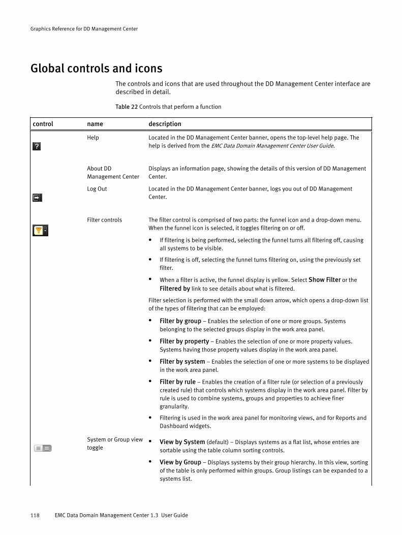
Global controls and iconsThe controls and icons that are used throughout the DD Management Center interface aredescribed in detail.
Table 22 Controls that perform a function
control name description
Help Located in the DD Management Center banner, opens the top-level help page. Thehelp is derived from the EMC Data Domain Management Center User Guide.
About DDManagement Center
Displays an information page, showing the details of this version of DD ManagementCenter.
Log Out Located in the DD Management Center banner, logs you out of DD ManagementCenter.
Filter controls The filter control is comprised of two parts: the funnel icon and a drop-down menu.When the funnel icon is selected, it toggles filtering on or off.
l If filtering is being performed, selecting the funnel turns all filtering off, causingall systems to be visible.
l If filtering is off, selecting the funnel turns filtering on, using the previously setfilter.
l When a filter is active, the funnel display is yellow. Select Show Filter or the
Filtered by link to see details about what is filtered.
Filter selection is performed with the small down arrow, which opens a drop-down listof the types of filtering that can be employed:
l Filter by group – Enables the selection of one or more groups. Systemsbelonging to the selected groups display in the work area panel.
l Filter by property – Enables the selection of one or more property values.Systems having those property values display in the work area panel.
l Filter by system – Enables the selection of one or more systems to be displayedin the work area panel.
l Filter by rule – Enables the creation of a filter rule (or selection of a previouslycreated rule) that controls which systems display in the work area panel. Filter byrule is used to combine systems, groups and properties to achieve finergranularity.
l Filtering is used in the work area panel for monitoring views, and for Reports andDashboard widgets.
System or Group viewtoggle
l View by System (default) – Displays systems as a flat list, whose entries aresortable using the table column sorting controls.
l View by Group – Displays systems by their group hierarchy. In this view, sortingof the table is only performed within groups. Group listings can be expanded to asystems list.
Graphics Reference for DD Management Center
118 EMC Data Domain Management Center 1.3 User Guide

Table 22 Controls that perform a function (continued)
control name description
System, Group,Tenant view toggle
Same as the previous icon, but you can also select:
l View by Tenant (default) – Displays tenants as a flat list, whose entries aresortable using the table column sorting controls.
Launch DD SystemManager
Starts DD System Manager in a new browser window for the selected system, whereyou can directly manage or investigate the corresponding area from where it waslaunched.
Show columns Found on many of the views that are table-based, enables the choice of columns thatdisplay in the table.
Column sorter On table views, sorts the columns in ascending or descending view (by date,alphabetically, by priority, etc), based on the column data type.
Add Opens a dialog to add one or more items. The type of item being added depends on
the page displayed. For example, on the Inventory > Systems page, this lets you add
systems to DD Management Center. On the Administration > Properties page, thislets you to create custom properties for managed objects.
Edit For a selected table element, opens a dialog that allows changing information aboutthe element.
Delete Deletes a selected table element.
Continue Continues an operation, such as adding another statement when creating a customrule.
You can select the icon to display a status banner with more information about theconnection problem.
Table 23 Icons showing system and/or connection status
icon status
Normal – Communication between DD Management Center and the DD system is operating normally.
Unreachable – The DD system is not responding or is not transmitting. Data was last retrieved as of thedate shown in the status banner.
Unmanaged – The DD system is suspended or unmanaged. When suspended, all data collection ceases.A system is suspended when management has been taken over by another DD Management Center orwhen the system is suspended using the CLI.
Adding – The DD system is being added into the inventory.
Upgrading – The DD system is being upgraded and is unavailable during this state.
Graphics Reference for DD Management Center
Global controls and icons 119

Table 23 Icons showing system and/or connection status (continued)
icon status
Synchronizing – Data for the DD system is being synchronized. The system is unavailable during thisstate.
Unsupported system – This system is unsupported because it is running an operating system that is notsupported by this version of DD Management Center. You may view system details for it, but the data willbe out of date. You will see a tooltip with an option to upgrade the system.
Table 24 Icons for Tenants and Tenant Units
icon status
Tenant Unit Configuration Issues – Reported in all multitenancy pages, dialogs, and lightboxes, indicatesthat this Tenant Unit has no configured alert notification list, no storage provisioned, no hard quota set,and/or no reports configured.
Dashboard controlsThe Dashboard > Monitoring page consists of from one to seven tabs that you create tohold any number of widgets that provide high-level, quick monitoring views of variousaspects of your Data Domain environment.
Table 25 Dashboard controls
controls name description
Add Widget Opens the Add Dashboard Widget dialog where you can select a widget template andoptional filters to create a widget.
Add/Configure Tabs Opens the Add and Configure Dashboard Tabs dialog where you can add tabs, modifytab names, or delete tabs. You can also set the number of columns and change theordering of the tabs across the dashboard.
Maximize/Restoredashboard
Toggles the size of the dashboard. Maximize hides the navigation panel and Restorereturns to default view, exposing the navigation panel.
Widget controlsEach widget includes the following standard controls.
controls name description
Edit Widget Opens the Edit Dashboard Widget where you can change the widget name and filtercriteria, and in some cases, widget details.
Graphics Reference for DD Management Center
120 EMC Data Domain Management Center 1.3 User Guide

controls name description
Details The global drill-down button on a widget that navigates to the parent page associated
with the widget. For example, for Alerts widgets, the Health > Alerts page is opened.
Help Provides information about what the widget monitors and active controls on thewidget, such as the control to navigate to the parent monitoring page.
Remove Widget Deletes the widget from the tab.
Connection Status Click Status to open a popup that lists the counts of DD systems with connectionproblems in any of these categories: (not responding, not transmitting, suspended,
and un-managed). Includes a link at the bottom of the popup to navigate to the Health> Status page that provides more details about just these systems.
Note
The Status control displays on a widget when any of the monitored systems (filtered orunfiltered) has one or more connection problems.
Filter Indicates a filter is active for the widget.
Emergency and Alert When an emergency or alert state is present, click this icon to open the Status > Alertspage to show the emergency/alert messages.
Critical and Error When critical or error states are present, click this icon to open the Status > Alertspage to show the critical/error messages.
Warning When a warning exists, click this icon to open the Status > Alerts page to show thewarning.
Group iconsOn the Administration > Groups page, the DD Management Center system administratorcreates groups in a tree-like hierarchy for logically organizing DD systems.
Table 26 Group icons
controls name description
Group Symbolizes a group containing DD systems or other groups. When subgroups arepresent, the expander icon is displayed to the left of the folder. Selecting the folderdisplays the members of the group in the Group Details panel.
Group withpermissions applied
Indicates that this group is controlled by access permissions.
Membership details Appears when a DD system belongs to more than one group. Hover to view the namesof groups of which this DD system is a member.
Graphics Reference for DD Management Center
Group icons 121
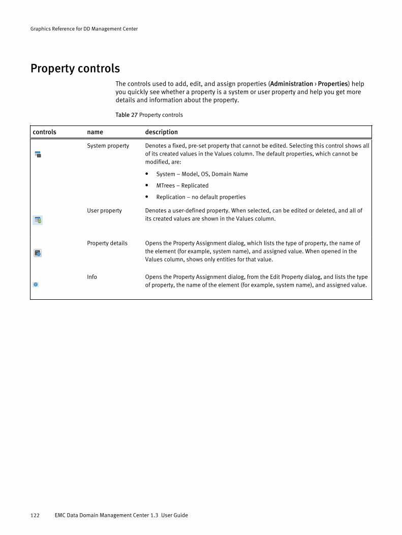
Property controlsThe controls used to add, edit, and assign properties (Administration > Properties) helpyou quickly see whether a property is a system or user property and help you get moredetails and information about the property.
Table 27 Property controls
controls name description
System property Denotes a fixed, pre-set property that cannot be edited. Selecting this control shows allof its created values in the Values column. The default properties, which cannot bemodified, are:
l System – Model, OS, Domain Name
l MTrees – Replicated
l Replication – no default properties
User property Denotes a user-defined property. When selected, can be edited or deleted, and all ofits created values are shown in the Values column.
Property details Opens the Property Assignment dialog, which lists the type of property, the name ofthe element (for example, system name), and assigned value. When opened in theValues column, shows only entities for that value.
Info Opens the Property Assignment dialog, from the Edit Property dialog, and lists the typeof property, the name of the element (for example, system name), and assigned value.
Graphics Reference for DD Management Center
122 EMC Data Domain Management Center 1.3 User Guide
APPENDIX B
Command Line Interface for DD ManagementCenter
l Differences between DDMC CLI and DD OS CLI.....................................................124l Tasks available only in DDMC CLI........................................................................ 124l managed-system commands...............................................................................124l task commands...................................................................................................129
Command Line Interface for DD Management Center 123

Differences between DDMC CLI and DD OS CLIThe DD Management Center CLI (command line interface) was derived from the DD OS(Data Domain Operating System) CLI, but has been modified to fit the needs and tasks ofDD Management Center.
l There are two unique DD Management Center commands (managed-system andtask) that perform basic registration, administration, and job managementfunctions.
l Only a subset (fifteen) of the DD OS commands (adminaccess, alerts, alias,authentication, autosupport, config, help, log, net, ntp, route, snmp,support, system, user) are included with DD Management Center; however,some arguments and output are not included because DD Management Center doesnot directly manage storage. The remaining DD OS commands are not includedbecause they are solely concerned with managing storage.
To see the online help for a CLI command in DD Management Center, start a secure shellsession (ssh), and type ? at the CLI prompt, or type mancommand-name.
Tasks available only in DDMC CLIIt is recommended that you use the DD Management Center GUI for all systemmanagement tasks. However, you must use the DD Management Center CLI for somesystem administration tasks that are not available in the GUI.
l managed-system resume host
l managed-system suspend host
l managed-system syncl system show performance [duration duration {hr | min}] [interval interval {hr |
min}]]
l system show serialno detailedThe GUI shows the current serial number for DD Management Center, but does notsupport the detailed version.
l system show spacel system show stats [view {net | iostat | sysstat}] [custom-view view-spec,...]
[interval nsecs] [count count]
managed-system commandsThe DD Management Center managed-system CLI commands let you add and removesystems from management, change their proxy host settings, and suspend, resume, orsynchronize data collection.
Note
You can also use the Web interface to perform these actions.
Command Line Interface for DD Management Center
124 EMC Data Domain Management Center 1.3 User Guide

managed-system addmanaged-system add hostname [force] [inbound-proxy proxy-host[inbound-proxy-port proxy-port]] [outbound-proxy proxy-host[outbound-proxy-port proxy-port]]This command adds a DD system to the set of managed DD systems. The commandprompts you to:
1. Verify that the certificate obtained from the host is valid.
2. Type the sysadmin password for the system being added to management.
Argument Definitions
forceIf the system is already being managed by another DD Management Center, thecurrent DD Management Center assumes management of the DD system from theother DD Management Center, and the DD system entry in the other DD ManagementCenter is placed in the unmanaged state. If the system is already being managedand you omit this argument, the command fails.
hostnameThe host name of the system.
inbound-proxy proxy-hostInbound proxy host name if the incoming connection from the DD system is througha proxy.
inbound-proxy-port proxy-portInbound proxy port number if the incoming connection from the DD system isthrough a proxy.
outbound-proxy proxy-hostOutbound proxy host name if the connection from the DD Management Center to theDD system is through a proxy.
outbound-proxy-port proxy-portOutbound proxy port number if the connection from the DD Management Center tothe DD system is through a proxy.
Note
The proxy options are equivalent to the firewall options in the graphical user interface.
Example# managed-system add host1234.mycompany.comThe SHA1 fingerprint for the remote host's CA certificate isXX:XX:XX:XX:XX:XX:XX:XX:XX:XX:XX:XX:XX:XX:XX:XX:XX:XX:XX:XXDo you want to trust this certificate? Are you sure? (yes|no) [no]: yes** Once added, all "admin" role users on this management center will operate on"host1234.mycompany.com" system with "admin" role. To allow "host1234.mycompany.com"to be managed by this management center, Enter sysadmin password:
ok, proceeding.
Command Line Interface for DD Management Center
managed-system add 125

managed-system check-connectionmanaged-system check-connection hostname [inbound-proxy proxy-host [inbound-proxy-port proxy-port]] [outbound-proxy proxy-host [outbound-proxy-port proxy-port]]This command checks whether the specified host is reachable and available to bemanaged by this DD Management Center. Use managed-system add to add thesystem to the set of systems that this DD Management Center is managing.
Argument Definitions
hostnameThe host name of the system.
inbound-proxy proxy-hostInbound proxy host name if the incoming connection from the DD system is througha proxy.
inbound-proxy-port proxy-portInbound proxy port number if the incoming connection from the DD system isthrough a proxy.
outbound-proxy proxy-hostOutbound proxy host name if the connection from the DD Management Center to theDD system is through a proxy.
outbound-proxy-port proxy-portOutbound proxy port number if the connection from the DD Management Center tothe DD system is through a proxy.
managed-system deletemanaged-system delete hostnameThis command removes the specified DD system from DD Management Centermanagement.
Argument Definitions
hostnameThe host name of the system.
managed-system resumemanaged-system resume hostnameThis command resumes data collection from the specified DD system if collection wassuspended by managed-system suspend.
Note
If a system is running an unsupported version of DD OS, it will be resumed, but it will beput back in an unsupported (not suspended) state.
Argument Definitions
hostnameThe host name of the system.
Command Line Interface for DD Management Center
126 EMC Data Domain Management Center 1.3 User Guide

managed-system setmanaged-system set hostname [inbound-proxy {proxy-host|none}][inbound-proxy-port {proxy-port|default}] [outbound-proxy{proxy-host|none}] [outbound-proxy-port {proxy-port|default}]This command sets or changes proxy server information for a managed system.
Argument Definitions
hostnameThe host name of the system.
inbound-proxy {proxy-host|none}Inbound proxy host name if the incoming connection from the DD system is througha proxy. Use none to remove the proxy host and clear the proxy port.
inbound-proxy-port proxy-portInbound proxy port number if the incoming connection from the DD system isthrough a proxy.
outbound-proxy {proxy-host|none}Outbound proxy host name if the connection from the DD Management Center to theDD system is through a proxy. Use none to remove the proxy host and clear theproxy port.
outbound-proxy-port {proxy-port|default}Outbound proxy port number if the connection from the DD Management Center tothe DD system is through a proxy. Use default to reset the proxy port number.
managed-system showmanaged-system show [{all | hostname}]This command prints basic information for a list of managed systems or the specifiedsystem.
Argument Definitions
allReport about all systems. This is the default.
hostnameThe host name of the system.
The report lists the systems by hostname and includes serial number, management state,online status, DD OS version, and latest synchronization time.
Management StatesThis list describes the possible values of the management State column.
addingThe DD Management Center is in the process of assuming management of thesystem.
deletingThe DD Management Center is in the process of ending management of the system.
managedThe DD Management Center is managing the system.
Command Line Interface for DD Management Center
managed-system set 127

suspendedThe DD Management Center is not currently managing and collecting informationabout the system. Systems go into this state if you use managed-systemsuspend to stop collecting data or a licensing problem prevents data collection.
unmanagedThe DD Management Center previously managed the system, but another DDManagement Center has assumed management.
unsupportedThis system is unsupported, because its DD OS version is not supported by thisversion of DD Management Center.
Management Status Values of “Managed” SystemsThis list describes the possible management Status values when a system is in themanaged state.
not-respondingDD Management Center has not been able to send messages to the managedsystem, or communication has failed in both directions, for more than 30 minutes.
not-transmittingThe managed system has not responded to messages from DD Management Centerfor more than 120 minutes.
onlineCommunication with the managed system is normal.
upgradingThe managed system is in the process of upgrading its DD OS.
upgrading, not-respondingThe managed system is in the process of upgrading its DD OS and is notcommunicating with DD Management Center.
managed-system suspendmanaged-system suspend hostnameThis command suspends data collection from the specified host. If you do not want DDManagement Center to show a system as unreachable while it is shut down formaintenance, you can use this command to suspend monitoring.
Note
If a system is not in a managed state, it cannot be suspended. If a system is running anunsupported version of DD OS, it can be suspended.
Argument Definitions
hostnameThe host name of the system.
managed-system syncmanaged-system syncThis command synchronizes and processes both current and historical data from allmanaged systems.
Command Line Interface for DD Management Center
128 EMC Data Domain Management Center 1.3 User Guide

task commandsIn the CLI, jobs are called tasks. The DD Management Center task CLI commands let youcancel, pause, resume, and generate reports about jobs. Regular users may work withtasks that they created. The sysadmin user may work on all tasks.
The Health > Jobs page in the Web interface displays information about jobs that havebeen initiated from DD Management Center, including jobs still in progress and jobs thathave completed, whether successfully or not. Jobs include actions such as adding andremoving systems from management.
task canceltask cancel task-idThis command terminates a task.
Argument Definitions
task-idThe ID number for the task, as reported by one of the task show commands.
task pausetask pause task-idThis command suspends a task. Use task resume to continue the task.
Argument Definitions
task-idThe ID number for the task, as reported by one of the task show commands.
task resumetask resume task-idThis command continues a task that you suspended with task pause.
Argument Descriptions
task-idThe ID number for the task, as reported by one of the task show commands.
task show activetask show active [type {inventory | replication | upgrade}][user user]This command reports about top-level running tasks. You can filter the results by usingtype with one of the keywords, or with the user keyword.
Argument Definitions
type {inventory | replication | upgrade}Filter the results to show only tasks of the specified type.
Command Line Interface for DD Management Center
task commands 129
user userFilter the results to show only tasks owned by the specified user.
task show detailedtask show detailed task-idThis command prints a detailed report about a single task and its subtasks.
Argument Definitions
task-idThe ID number for the task, as reported by one of the task show commands.
task show detailed-activetask show detailed-active [type {inventory | replication |upgrade}] [user user]This command prints a detailed report about active tasks and their subtasks. You canfilter the results by using type with one of the keywords, or with the user keyword.
Argument Definitions
type {inventory | replication | upgrade}Filter the results to show only tasks of the specified type.
user userFilter the results to show only tasks owned by the specified user.
task show detailed-historytask show detailed-history [last n {hours | days | weeks |months}] [start MMDDhhmm[[CC]YY] end MMDDhhmm[[CC]YY] [type{inventory | replication | upgrade}] [user user]This command prints a detailed report about completed tasks and their subtasks. Youcan filter the results by using type with one of the keywords, or with the user keyword.You can filter the results by time by using the last, start, and end keywords. Thedefault reporting period is the past 24 hours.
Argument Definitions
last n {hours | days | weeks | months}Filter the results to show only tasks that finished during the previous n hours,days, weeks, or months.
start MMDDhhmm[[CC]YY] end MMDDhhmm[[CC]YY]Filter the results to show only tasks that finished during the specified interval. MMDDindicates month and day. hhmm indicates hours and minutes in 24-hour format. Tospecify midnight between Sunday night and Monday morning, use mon 0000. Tospecify noon on Monday, use mon 1200. CC is the first two digits of the year. YY isthe last two digits of the year.
type {inventory | replication | upgrade}Filter the results to show only tasks of the specified type.
user userFilter the results to show only tasks owned by the specified user.
Command Line Interface for DD Management Center
130 EMC Data Domain Management Center 1.3 User Guide

task show historytask show history [last n {hours | days | weeks | months}][start MMDDhhmm[[CC]YY] end MMDDhhmm[[CC]YY] [type {inventory |replication | upgrade}] [user user]This command prints a brief report about completed tasks. You can filter the results byusing type with one of the keywords, or with the user keyword. You can filter theresults by time by using the last, start, and end keywords. The default reportingperiod is the past 24 hours.
Argument Definitions
last n {hours | days | weeks | months}Filter the results to show only tasks that finished during the previous n hours,days, weeks, or months.
start MMDDhhmm[[CC]YY] end MMDDhhmm[[CC]YY]Filter the results to show only tasks that finished during the specified interval. MMDDindicates month and day. hhmm indicates hours and minutes in 24-hour format. Tospecify midnight between Sunday night and Monday morning, use mon 0000. Tospecify noon on Monday, use mon 1200. CC is the first two digits of the year. YY isthe last two digits of the year.
type {inventory | replication | upgrade}Filter the results to show only tasks of the specified type.
user userFilter the results to show only tasks owned by the specified user.
Command Line Interface for DD Management Center
task show history 131

Command Line Interface for DD Management Center
132 EMC Data Domain Management Center 1.3 User Guide