manual 58ghz wirelesslink en - abc of fm radio and tv
TRANSCRIPT

Brought to you by PCS Electronics, www.pcs-electronics.com
5GHz microwave audio-video link system Setting up short manual
Manual

Brought to you by PCS Electronics, www.pcs-electronics.com
IMPORTANT NOTE
Upon receiving your order inspect the packaging material and unit for apparent damage.
Any damage should be reported immediately so we can make a claim with the shipping
company. Take photos, if you can, they can be used as a proof.
IMPORTANT! Study local regulations and ensure you are operating in compliance.
Never ever operate any exciter/transmitter or amplifier without a properly tuned
load/antenna!

Brought to you by PCS Electronics, www.pcs-electronics.com
Table of Contents
5,8GHz wireless audio/video link sytem ................................... 1
Description ...................................................................................... 1
Highlights ........................................................................................ 1
What is included in our basic 5GHz Video/Audio link system (3Km
max)? .............................................................................................. 1
How can this be extended for more range? .................................... 1
Setup and installation ............................................................... 2
Troubleshooting ....................................................................... 6
Appendix A – Warranty and legal info ...................................... 7
Important notice! ............................................................................. 7
Warranty and servicing! .................................................................. 7
Legal info ........................................................................................ 7
Limitation of liability ......................................................................... 7
Also available from www.pcs-electronics.com ................................ 8
Revisions and errata ................................................................ 9

Brought to you by PCS Electronics, www.pcs-electronics.com
5,8GHz wireless audio/video link sytem
Description
This product is based on outdoor-mounted 5.8GHz wireless audio/video system with optionally added 1W power amplifier and high-gain grid antennas. It lets you send stereo audio and video wirelessly up to about 20Km far. Range is limited by line of sight so make sure there are no objects between receiver and transmitter.
Highlights
1. Works on 5.8GHz band.
2. Power supply needed: 12V for receiver, transmitter and 1W amplifier, can work from mains or battery
3. Stereo audio and analog video
4. For best range use 1W amplifier and high-gain grid/dish antennas.
What is included in our basic 5GHz Video/Audio link system (3Km max)?
1x Receiver in weatherproof enclosure with integrated panel antenna
1x Transmitter in a weatherproof enclosure with integrated panel antenna
2x Mounting brackets integrated into receiver and transmitter
2x Universal mains power supplies to convert 110-240V AC to 12 volts DC, 1A
1x Manual
How can this be extended for more range?
1. By adding 1W amplifier
2. By adding high-gain grid antenna
Chapter
1

Brought to you by PCS Electronics, www.pcs-electronics.com
Setup and installation
1. Receiver and transmitter
Fig.1: Receiver and transmitter shown from behind
You will need to remove the back of the plastic box hiding behind the panel antenna, now you will have to attach audio/video cables and power to the 6-pin screw terminal. The pinout is as follows and is also shown on the PCB board:
GND - Audio signal ground
A-L - Audio left channel
A-R - Audio right channel
GND – power supply negative
+12V – power supply positive, 9-13V, minimum 500mA
Making these connections requires some basic skills. You are required to know how to solder connectors to cable for example. Set the required channel according to the table. Now put the cover back and screw the mounting bracket to the base of device. Using the mounting clamp, attach the device to a sturdy antenna rod with antenna directed to an receiving point. The polarity and channel number must be same for both interacting transmit/receive devices. There is the adjusting trimmer within transmitting part for setting the video-contrast, which enables proper matching of signal source connected.
Chapter
2

Brought to you by PCS Electronics, www.pcs-electronics.com
Fig.2: Setting receive and transmit channel
Fig.3: Specifications
If you’ve been careful you should now have video and sound on your receiving end.
Brought to you by PCS Electronics, www.pcs-electronics.com
2. Connecting high-gain grid antenna for more range
To extend the range you can disconnect the built-in panel antenna and connect the external high gain antenna. To do this simply remove the plastic cover of receiver/transmitter and disconnect the SMA connector from the antenna inside. Now connect the coaxial cable from external antenna to the receiver or transmitter.
Note: High gain antennas require more precise adjustment, the antenna must be positioned to point exactly at the other antenna.
3. Assembling high-gain grid or dish antenna
For assembling grid or dish high-gain antennas observe instructions included with antenna
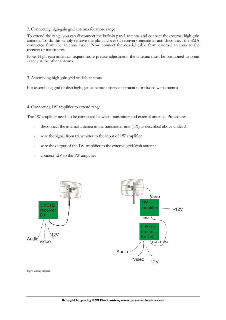
4. Connecting 1W amplifier to extend range
The 1W amplifier needs to be connected between transmitter and external antenna. Procedure:
- disconnect the internal antenna in the transmitter unit (TX) as described above under 3
- wire the signal from transmitter to the input of 1W amplifier
- wire the output of the 1W amplifier to the external grid/dish antenna
- connect 12V to the 1W amplifier
Fig.4: Wiring diagram

Brought to you by PCS Electronics, www.pcs-electronics.com

Brought to you by PCS Electronics, www.pcs-electronics.com
Troubleshooting
PROBLEM DESCRIPTION POSSIBLE SOLUTIONS
No known issues
Chapter
3

Brought to you by PCS Electronics, www.pcs-electronics.com
Appendix A – Warranty and legal info
Important notice!
Please remember to turn off the transmitter/amplifier when not in use! This goes especially for high powered transmitters. Remember that anything you broadcast through the transmitter can be heard by anyone tuning in to that frequency. Although it is unlikely certain weather conditions may allow the signal to go further than your immediate listening area so please don't broadcast anything you don't mind anyone else hearing.
Warranty and servicing!
Within one (1) year of receiving your order, if any product proves to be defective; please contact us via e-mail or our feedback form. Please DO NOT ship the product back to us without contacting us first and receiving return instructions. After we receive the defective merchandise, we will test it if need be, and we will ship back to you a non-defective replacement product. Please note that this doesn't cover final RF transistor as it can be damaged by using defective or poorly matched antenna. An exception is as well any mishandling or abuse by the customer. If the product is defective, you will receive a replacement. If you choose to return the defective item, rather than replace it, we will charge a 20% restocking fee and your original shipping and handling charges will not be refunded. The return of the product is at your expense. We believe that this is a fair policy because lower overhead results in lower prices for all of our customers.
Legal info
It may be illegal to operate this device in your county. Please consult local authorities before using our products! PCS Elektronik d.o.o. is not responsible for any damage to your PC arising from use of this product and will not be held responsible for any violation of local laws pertaining to the use of this product. It is entirely your responsibility that you make sure you operate in accordance with local laws and/or regulations.
Limitation of liability
To the law, in no event shall PCS Elektronik d.o.o. or its suppliers be liable for any special, incidental, indirect, or consequential damages whatsoever (including, without limitation, damages for loss of business profits, business interruption, loss of business information, or any other pecuniary loss) arising out of the use of or inability to use the PRODUCT, even if PCS Elektronik d.o.o. has been advised of the possibility of such damages. In any case, PCS Elektronik d.o.o.´s entire liability under any provision of this agreement shall be limited to the greater of the amount actually paid by you for the PRODUCT or U.S. $5.00; because some states and jurisdictions do not allow the exclusion or limitation of liability, the above limitation may not apply to you.
Appendix
A

8
Also available from www.pcs-electronics.com
We also carry a big range of:
- FM transmitters in assembled and KIT form
- TV transmitters in assembled and KIT form, VHF and UHF
- AM transmitters with extremely clear modulation (PWM design)
- Various accessories for professional and hobby FM radio stations
- A large assortment of hard to obtain RF components (RF transistors; MRF, 2SC, coils, silver plated wire, coaxial cable, capacitors, quartz crystals and many others)
- PC based FM transmitters (PCI MAX pc based FM transmitter turns your PC into a radio station)
- A large number of beginners guides to get you started
- A large selection of free schematics is as well available at our website.
If you can’t get much range with your homebrew antenna, have a look at these: http://www.pcs-electronics.com

9
Revisions and errata
V1.0 (May, 2015): Release version
Please report any errors you see in this manual, you will be helping us and many other users out there. Thank you!