manual de instalación (pdf)
TRANSCRIPT

D MM U L T I R A D I OD O M O S E i
(+) Alimentación 15 V(+) 15 Vcc Power supply
MasaGround
Audio, Scan y ON/OFF AlimentadoresAudio, Scan and Power supply ON/OFF
Audio y TelecontrolAudio and Telecontrol
Audio y ScanAudio and Scan
Audio y TelecontrolAudio and Telecontrol
Audio y ScanAudio and Telecontrol
Audio y TelecontrolAudio and Telecontrol
Audio y ScanAudio and Telecontrol
Audio y TelecontrolAudio and Telecontrol
Audio de intercomunicaciónIntercom Audio
Control Digital intercomunicaciónIntercom data line
Salida altavoz (+)Speaker ouput (+)
Salida altavoz (común)Speaker ouput (common)
Salida altavoz (+) + Stand-by Amplif.Speaker ouput (+) + Stand-by Amplif.
— 2 —
3"
PARA CENTRALES / FOR CENTRAL UNITS
V11F
a: 130 b: 265 c: 45
V12F
a: 140 b: 275
PARA ALTAVOCES / FOR SPEAKERS
8"
V17B
Ø 250 x 100
V18B
Ø 265
5"V22E
a: 320 b: 230 c: 120
b
a
c
PARA MANDOS / FOR CONTROL UNITS
V13D
a: 79 b: 144 c: 45
V14D
a: 70 b: 137
V21A
Ø 185
H28N
Ø 180 x 115Agujero / Hole Ø 156
V19A
Ø 175 x 100
V29A
Ø 175 x 85
2"
Ø 90 x 55Agujero / Hole Ø 73
2"
V15C
a: 91 b: 98 c: 45
CAJAS DE EMPOTRAR Y TAPAS PARA PREINSTALACION / BOXES TO BUILD-IN AND PRE-INSTALLATION COVERS
PARA BAFLES / FOR BAFFLES
Sr. Instalador: En primer lugar, le agradecemos que haya elegido nuestros productos y le deseamos que la instalación funcione perfectamentey "a la primera". Para ello le rogamos siga cuidadosamente las instrucciones que le ofrecemos en este Manual.
Por nuestra parte, hemos dotado a todos los módulos de las protecciones adecuadas para que, en caso de error de conexión, no se produzcan averíasy pueda subsanarse fácilmente. Si a pesar de todo tiene algún problema o duda que resolver, no dude en ponerse en contacto con nuestros delegadoso directamente con nuestro Soporte Técnico al Cliente. Estamos para ayudarle.
Mr. Installer: First of all, we would like to thank you for choosing the EGi products. We wish with you that the installation works perfectlyfrom the very beginning. In order to achieve it, please, follow carefully the instructions that we offer you in this manual.
For our part, we have put in all our modules the appropiate protections in order to avoid damages in the case of a mistaken connection,so you can fix it easily. Notwithstanding that, if you have any problem or doubt, to resolve it, do not hesitate to contact our agent ordirectly with our Technical Customer Service. We are here to help you.
Line length
Total number of Control units per installation
Number of D26D Control units per installation
Number of J12U or D28D Modules per installation
Number of E17G or E18G amplifiers per installation ( * see page 33)
Number of E17G or E18G amplifiers per Control unit
Number of D44U or D45U with Scan per installation
MAXIMO / MAXIMUM
250 m.
30 u.
10 u.
15 u.
4 u. ( * 20 u.)
4 u.
10 u.
LIMITS OF THE INSTALLATION LIMITACIONES DE LA INSTALACION
Longitud de las líneas
Nº total de Mandos por instalación
Nº de Mandos D26D por instalación
Nº de Módulos J12U o D28D por instalación
Nº de amplificadores E17G o E18G por instalación ( * ver pág. 33)
Nº de amplificadores E17G o E18G por Mando
Nº de Mandos D44U o D45U con Scan por instalación
cana
l /
chan
nel2
cana
l /
chan
nel3
cana
l /
chan
nel4
cana
l /
chan
nel1
Alim
enta
ción
Pow
er s
uppl
y
Cables de hilos de coloresColour wires cables
36
8
38
10, 12
6, 815, 16
11
9
14
13
7
5
3
1
4
2
20
1718
19
2
Hilo mm2 Función Tensión C. PlanoWire mm2 Function Voltage Flat Cable
455
35
+L
R+
15 V
0 V
3 V Audio+ 7 V
3 V Audio+ 7 V
4.5 V Audio+ 3 V
4.5 V Audio
0 V
1
1
0.4
0.4
0.4
0.4
0.4
0.4
0.4
0.4
0.4
0.4
0.75
0.75
0.75
R
L
1
9A
6
7
373 V Audio+ 7 V
3 V Audio+ 7 V
3 V Audio+ 7 V
Señal DigitalDigital signal
3 V Audio+ 7 V
3 V Audio+ 7 V
3 V Audio+ 7 V
3 V Audio+ 7 V
Inte
rcom
CABL
ES A
LTAV
OZ
SPEA
KER
WIR
ES
Cables de la serie DOMOSDOMOS series wires
R14N/C - R20N/C
R16N
R14N - R20N
R18N - R18N/C Cable de 4 hilos de colores para instalaciones de 1 canal de música.
4 colour wires cable for installations with 1 music channel.
R19N - R19N/C Cable de 6 hilos de colores para instalaciones de 1 canal de música + intercom.
6 colour wires cable for installations with 1 music channel + intercom.
R15N - R15N/C Cable de 8 hilos de colores para instalaciones de 2 canales de música + intercom.
8 colour wires cable for installations with 2 music channels + intercom.
R13N - R13N/C Cable de 12 hilos de colores para instalaciones de 4 canales de música + intercom.
12 colour wires cable for installations with 4 music channels + intercom.
R18N - R19N - R15N - R13N
Cables planosFlat wires
R14N - R14N/C Cable Plano de 14 vías para instalaciones de hasta 4 canales de música +intercom.
14 ways ribbon wire for installations with up to 4 music channels +intercom.
R20N - R20N/C Cable Plano de 20 vías para instalaciones de hasta 4 canales de música +intercom.
20 ways ribbon wire for installations with up to 4 music channels +intercom.
R16N Cable Plano de 14 vías + 2 hilos de alimentación para instalaciones de hasta4 canales de música + intercom.
14 ways + 2 power supply wires ribbon wire for installations with upto 4 music channels + intercom.
R18N/C - R19N/CR15N/C - R13N/C
0196
0197
0231
0204
0360
0439
0440
0212
_B
0441
0438
_A
0419
_C
0419
_B
0513
0419
_D
0209
_A
0211
_A02
58
0628
0267
Dimensiones en mmSizes in mm
Caja eléctrica Ø 60 con tornillosØ 60 standard fitting box with screws07
20
V16C
91
D

D MM U L T I R A D I OD O M O S
— 3 —
ALTAVOCES JUNTO AL MANDOSPEAKERS NEXT TO THE CONTROL UNIT
0652
Línea GeneralGeneral Line Ø 16 mm
PREINSTALACION DE CAJAS Y CONDUCTOS / BOXES AND PIPES PRE-INSTALLATION
CONEXION DE CENTRALCONNECTION OF CENTRAL UNIT
CONEXION EN CAJA DE DERIVACIONCONNECTION IN THE JUNCTION BOX
0653
Línea GeneralGeneral LineØ 16 mm
0649
Línea GeneralGeneral LineØ 16 mm
CONEXION EN ALTAVOZCONNECTION IN THE SPEAKER
CONEXION EN MANDOCONNECTION IN THE CONTROL UNIT
0650 0651
Línea GeneralGeneral LineØ 16 mm
Línea GeneralGeneral Line
Ø 16 mm
2º altavoz stereo (opcional)2nd stereo speaker (optional)
2º altavoz stereo (opcional)2nd stereo speaker (optional)
0793
Línea GeneralGeneral Line Ø 16 mm
2º altavoz stereo (opcional)2nd stereo speaker (optional)
l
D MM U L T I R A D I OD O M O SIN
STA
LAC
ION
INST
AL
LA
TIO
NM
ATE
RIA
LES
MO
DU
LE
S
230 V~
CENTRAL
COCINAKITCHEN
SALONLOUNGE
BAÑOBATHROOM
0671_A 0672_A
230 V~
Línea GeneralGeneral Line
CENTRAL
Fuente musicalMusical source
COCINAKITCHEN
SALONLOUNGE
A LA PLANTA SUPERIORUPSTAIRS
PLANTA BAJADOWNSTAIRS
0373
Opción más sencilla:Mando mono + altavoz de 3" adosado
The simplest option:1 mono Control unit + 3" attachedloudspeaker
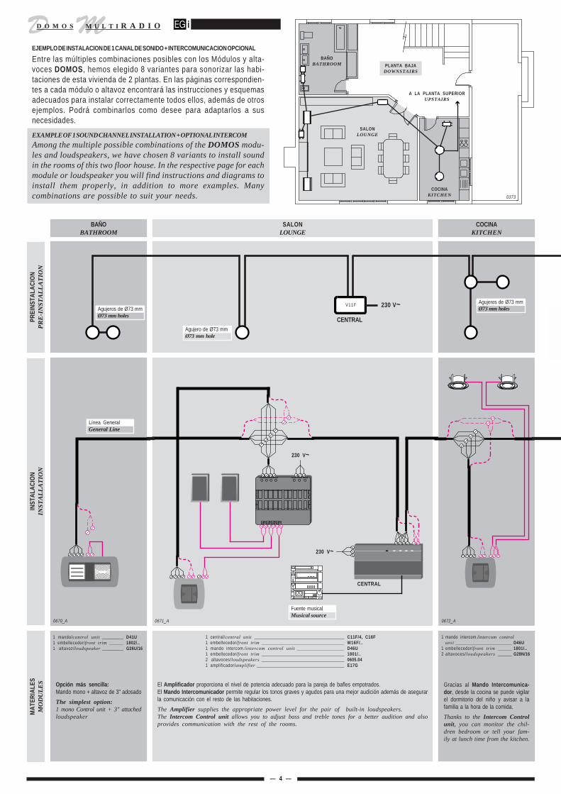
El Amplificador proporciona el nivel de potencia adecuado para la pareja de bafles empotrados.El Mando Intercomunicador permite regular los tonos graves y agudos para una mejor audición además de asegurarla comunicación con el resto de las habitaciones.
The Amplifier supplies the appropriate power level for the pair of built-in loudspeakers.The Intercom Control unit allows you to adjust bass and treble tones for a better audition and alsoprovides communication with the rest of the rooms.
Gracias al Mando Intercomunica-dor, desde la cocina se puede vigilarel dormitorio del niño y avisar a lafamilia a la hora de la comida.
Thanks to the Intercom Controlunit, you can monitor the chil-dren bedroom or tell your fam-ily at lunch time from the kitchen.
— 4 —
230 V~
EJEMPLO DE INSTALACION DE 1 CANAL DE SONIDO + INTERCOMUNICACION OPCIONAL
Entre las múltiples combinaciones posibles con los Módulos y alta-voces DOMOS, hemos elegido 8 variantes para sonorizar las habi-taciones de esta vivienda de 2 plantas. En las páginas correspondien-tes a cada módulo o altavoz encontrará las instrucciones y esquemasadecuados para instalar correctamente todos ellos, además de otrosejemplos. Podrá combinarlos como desee para adaptarlos a susnecesidades.
EXAMPLE OF 1 SOUND CHANNEL INSTALLATION + OPTIONAL INTERCOM
Among the multiple possible combinations of the DOMOS modu-les and loudspeakers, we have chosen 8 variants to install soundin the rooms of this two floor house. In the respective page for eachmodule or loudspeaker you will find instructions and diagrams toinstall them properly, in addition to more examples. Manycombinations are possible to suit your needs.
PREI
NST
ALA
CIO
NP
RE
-IN
STA
LL
AT
ION
BAÑOBATHROOM
1 mando/control unit _________ D41U1 embellecedor/front trim ______ 1802/..1 altavoz/loudspeaker _________ G26U/16
1 mando intercom./intercom controlunit ________________________ D46U
1 embellecedor/front trim ______ 1801/..2 altavoces/loudspeakers ______ G28N/16
1 central/central unit ______________________________________ C11F/4, C18F1 embellecedor/front trim ___________________________________ W16F/..1 mando intercom./intercom control unit ____________________ D46U1 embellecedor/front trim ___________________________________ 1801/..2 altavoces/loudspeakers ___________________________________ 0605.041 amplificador/amplifier _____________________________________ E17G
0670_A
V11F Agujeros de Ø73 mmØ73 mm holes
Agujero de Ø73 mmØ73 mm hole
Agujeros de Ø73 mmØ73 mm holes
sf

D MM U L T I R A D I OD O M O S
DORMITORIO PRINCIPALMAIN BEDROOM
BAÑOBATHROOM
DORMITORIO NIÑOCHILDREN BEDROOM
DORMITORIO JOVENTEENAGERS BEDROOM
BAÑOBATHROOM
0673_A 0674_A 0675_A 0676 0677_A
230 V~ 230 V~
0377
PLANTA SUPERIORUPSTAIRS
DE LA PLANTA BAJAFROM DOWNSTAIRS
El Amplificador y los altavoces HI-FIde 8" empotrados en el techo permitena los jóvenes disfrutar de su walkman®a toda potencia.
The Amplifier and the 8" HI-FIloudspeakers , built-in at theceiling, allow the young ones toenjoy their walkman® with themaximum power.
Dado el tamaño del dormitorio sehan colocado 4 altavoces de 5Wde potencia cada uno.
Because the size of thisbedroom, four loudspeakershave been installed with apower of 5W each.
El Mando a Distancia permite mane-jar la música desde la bañera.
The Remote control allows youto select and regulate the musicfrom the bathing tub.
El Mando Intercomunicador permi-te vigilar al niño desde el dormitorio delos padres, cocina y salón.
The Intercom Control unit al-lows you to monitor the childrenfrom the main bedroom, kitchenor lounge.
El baño tiene techo de escayola; elAro H28N facilita la colocación delaltavoz sin necesidad de fijar con yesouna caja de empotrar.
The bathroom ceiling is made ofplaster; the H28N ring makeseasier the installation of theloudspeaker. It is not necessaryto fix with plaster a backbox.
— 5 —
DORMITORIO JOVENTEENAGERS
BEDROOM
DORMITORIO NIÑOCHILDRENBEDROOM
2 hilos Intercom. (opcional)2 wires for Intercom (optional)
4 hilos Sonido4 wires for sound
Regleta de ConexiónConnection strip
BAÑOBATHROOM
BAÑOBATHROOM
DORMITORIO PRINCIPALMAIN BEDROOM
1 mando/control unit _________ D47U1 embellecedor/front trim ______ 1801/..1 altavoz/loudspeaker _________ G28N/16
1 mando intercom./intercom controlu n i t _______________________ D46U
1 embellecedor/front trim ______ 1802/..1 altavoz/loudspeaker _________ G13U/16
1 mando/control unit __________ D42U1 embellecedor/front trim _______ 1801/..1 amplificador/amplifier _________ E17G2 altavoces/loudspeakers ________ G12B/42 rejillas/grilles __________________ 0603.10
2 altavoces/loudspeakers _______ G14A/162 rejillas/grilles _________________ 0602.101 amplificador/amplifier _________ M16N1 mando a distancia/remote control M13N1 aro adaptador/adapter ___________ H28N
1 mando intercom./intercom controlu n i t ________________________ D46U
1 embellecedor/front trim _______ 1801/..1 amplificateur/versterker ________ E17G4 altavoces/loudspeakers _______ G14A/44 rejillas/grilles _________________ 0602.10
HILOS DE LA LINEA GENERALGENERAL LINE WIRES
Ref. CableCable Reference
PrestacionesCharacteristics
4 R18N
6 R19N
Nº de hilosNr. of wires
1 canal de sonido + intercom1 sound channel + intercom
8 R15N
2 canales de sonido + intercom + portero(sólo con Centrales de 2 canales C17F, C16F, C14F y
Mandos de 2 canales D46U, D26D)2 sound channels + intercom + door entry system(only with 2-channel Central units C17F, C16F,C14F and 2-channel Control units D46U, D26D)
1 canal de sonido1 sound channel
V17B V17B H28N H28N V19A V19A
V19A
V19A
Agujero de Ø73 mmØ73 mm hole
Agujero de Ø73 mmØ73 mm hole
Agujeros de Ø73 mmØ73 mm holes
Agujeros de Ø73 mmØ73 mm holes
fh

D MM U L T I R A D I OD O M O SPR
EIN
STA
LAC
ION
PR
E-I
NST
AL
LA
TIO
NIN
STA
LAC
ION
INST
AL
LA
TIO
NM
ATE
RIA
LES
MO
DU
LE
S
V15CV13D
ENTRADAHALL
SALONLOUNGE
BAÑOBATHROOM
0684 0679_A 0678_A
COCINAKITCHEN
0683
230 V~
V13D
V19A V19A
Línea GeneralGeneral Line
230 V~
Línea GeneralGeneral Line
Línea Portero automáticoDoor entry system line
(4 +
1)
V13D
V22EV22E
230 V~
Conducto de 1616 mm pipe
CENTRAL Caja de empotrar100 x 100 mm.100 x 100 mm. built-in boxAl
por
tero
To
the
open
ent
ry s
yste
m
— 6 —
V11F
EJEMPLO DE INSTALACION DE 4 CANALES DE SONIDO + INTERCOMUNICACION OPCIONAL
Entre las múltiples combinaciones posibles con los Módulos y alta-voces DOMOS, hemos elegido 8 variantes para sonorizar las habi-taciones de esta vivienda de 2 plantas. En las páginas correspondien-tes a cada módulo o altavoz encontrará las instrucciones y esquemasadecuados para instalar correctamente todos ellos, además de otrosejemplos. Podrá combinarlos como desee para adaptarlos a susnecesidades.
EXAMPLE OF A 4 SOUND CHANNEL INSTALLATION + OPTIONAL INTERCOM
Among the multiple possible combinations of the DOMOS modu-les and loudspeakers, we have chosen 8 variants to install soundin the rooms of this two floor house. In the respective page for eachmodule or loudspeaker you will find instructions and diagrams toinstall them properly, in addition to more examples. Manycombinations are possible to suit your needs. 0373
COCINAKITCHEN
SALONLOUNGE
A LA PLANTA SUPERIORUPSTAIRS
PLANTA BAJADOWNSTAIRS
BAÑOBATHROOM
1 ó 2 Centrales1 or 2 Central units
1 mando/control unit _______ D13D1 embellecedor/front trim ____ W12D/..1 marquillo/frame ____________ W13D/..1 altavoz/loudspeaker _______ G19C/161 rejilla/grille _______________ H21C/..
1 mando/control unit _______ D13D1 embellecedor/front trim ____ W12D/..2 altavoces/loudspeakers ____ G14A/162 rejillas/grilles _____________ H..A/ . .
1 interface/interface _________ J11G/B
Opción más sencilla:Mando mono + altavoz de 3" adosado
The simplest option:1 mono Control unit + 3" at-tached loudspeaker
El Amplificador proporciona el nivel de potencia adecuado para la parejade bafles empotrados.El Mando Intercomunicador permite regular los tonos graves y agudospara una mejor audición además de asegurar la comunicación con el restode las habitaciones.
The Amplifier supplies the appropriate power level for the pairof built-in loudspeakers.The Intercom Control unit allows you to adjust bass and trebletones for a better audition and also provides communicationwith the rest of the rooms.
Con el J11G/B se puede conectar lainstalación de sonido con algunosmodelos de portero automático paramanejarlo desde los Mandos D28D.
With the J11G/B you canconnect the sound installationto some models of door entrysystems, and control it with theD28D Control units.
4 canales de sonido stereo.
4 stereo sound channels.
1 central/central unit _________________________ C12F, C14F, C16F, C17F1 embellecedor/front trim ______________________ W16F/..1 mando/control unit _________________________ D28D1 altavoz/loudspeaker _________________________ G22E/41 amplificador/amplifier ________________________ E17G1 módulo de conexión/connecting device _________ I21D1 emisor IR/IR transmitter _____________________ M18U1 cápsula/IR capsule __________________________ M19N
sf

D MM U L T I R A D I OD O M O S
DORMITORIO PRINCIPALMAIN BEDROOM
BAÑOBATHROOM
DORMITORIO NIÑOCHILDREN BEDROOM
DORMITORIO JOVENTEENAGERS BEDROOM
BAÑOBATHROOM
V15CV13DV15C
V13D
V13D
V17B V17B V19A V19A
V19A
V13D
V19A
0682 0685 0681_A 0686 0680_A
V19AV19A
230 V~
0377
PrestacionesCharacteristics
6
8
Nº de hilosNr. of wires
1 canal de sonido + intercom + zonas + reloj + portero1 sound channel + intercom + zones + clock + door entry system
2 canales de sonido +intercom + zonas + reloj + portero2 sound channels + intercom + zones + clock + door entry system
124 canales de sonido +intercom + zonas + reloj + portero
4 sound channels + intercom + zones + clock + door entry system
R19N
R15N
R13N
V13D
230 V~
Agujeros Ø 73 mmØ 73 mm holes
DORMITORIO PRINCIPALMAIN BEDROOM
PLANTA SUPERIORUPSTAIRS
— 7 —
Los Mandos D28D mostrados en el salón y dos dormitorios disponen, ademásde 4 canales de música stereo, de reloj despertador, intercomunicación porzonas y control del portero automático.
The D28D Control units shown in the lounge and in two bedroomsinclude, in addition to 4 stereo music channels, an alarm clock,intercom between zones and control of the door entry system.
Cab
le p
lano
R20
NR
20N
ribb
on w
ire
DE LA PLANTA BAJAFROM DOWNSTAIRS
BAÑOBATHROOM
DORMITORIO JOVENTEENAGERS
BEDROOM
HILOS DE LA LINEA GENERALGENERAL LINE WIRES BAÑO
BATHROOM
DORMITORIO NIÑOCHILDRENBEDROOM
Ref. CableCable Reference
1 mando/control unit ______ D13D1 embellecedor/front trim ___ W12D/..2 altavoces/loudspeakers ___ G28N/16
1 mando/control unit _______ D28D1 marquillo/frame ___________ W13D/BL2 altavoces/loudspeakers ____ G19C/162 rejillas/grilles _____________ H21C/BL1 módulo de conexión/
connecting device _______ I21D
1 mando/control unit ________ D13D1 marquillo/frame _____________ W12D/..2 altavoces/loudspeakers _____ G12B/42 rejillas/grilles ______________ H..B/ . .1 amplificador/amplifier _______ E17G2 receptores IR/IR signal ______ M17U.1
2 altavoces/loudspeakers _____ G14A/162 rejillas/grilles ______________ H..B/..1 amplificador/amplifier _______ M16N1 mando a distancia/
remote control_ _____________ M13N
1 mando/control unit ________ D28D4 altavoces/loudspeakers _____ G14A/44 rejillas/grilles ______________ 0602.101 amplificador/amplifier _______ E17G1 módulo de conexión/
connecting device _________ I21D1 receptor IR/IR signal ________ M17U
El Amplificador y los altavoces HI-FIde 8" empotrados en el techo permitea los jóvenes disfrutar de su walkman®a toda potencia.
The Amplifier and the 8" HI-FIloudspeakers , built-in at theceiling, allow the young ones toenjoy their walkman® with themaximum power.
Dado el tamaño del dormitorio sehan colocado 4 altavoces de 5Wde potencia cada uno.
Because the size of thisbedroom, four loudspeakershave been installed with apower of 5W each.
El Mando a Distancia permite mane-jar la música desde la bañera.
The Remote control allows youto select and regulate the musicfrom the bathing tub.
El Mando Intercomunicador permi-te vigilar al niño desde el dormitorio delos padres, cocina y salón.
The Intercom Control unitallows you to monitor thechildren from the main bedroom,kitchen or lounge.
El baño tiene techo de escayola; elaltavoz G28N/16 se coloca tan fácil-mente como un foco halógeno.
The bathroom ceiling is made ofplaster; the G28N/16 loud-speaker can be installed as eas-ily as an halogen light.
Cable plano R20NR20N ribbon wire
fh

D MM U L T I R A D I OD O M O S
— 8 —
ESPECIFICACIONES
Alimentación red
Consumo
Bases de red telecontroladas
Salida de tensión continua
Telecontrol (activ / desactiv)
SPECIFICATIONS
Mains power supply
Consumption
Telecontrolled mains sockets
DC output
Telecontrol (ON / OFF)
230 V~ ± 10% • 50/60 Hz
3 VA, 4.5 VA, 6 VA (max. 30 VA)
max. 200 VA max. 2 x 200 max. 4 x 200 VA
15 V • 1.2 A
1.5 / 5 s.
C11F/4 C17F C12F
Desmontar el embellecedorTrim disassembly 0109
[ 2 ]
[ 1 ]
2
CENTRALES / CENTRAL UNITS C11F/4 - C17F - C12FLa Central alimenta en 15V y proporciona señal de Audio a todos los módulos de la Instalación. Susentradas de audio universales admiten cualquier fuente musical. Cada canal dispone de una base de redtelecontrolada para encender y apagar su fuente musical desde cualquier lugar de la instalación. LasCentrales C17F y C12F admiten línea general de hilos o de cable plano a elección del instalador.
The Central unit supplies 15V and provides audio signal to all the modules in the EGiinstallation. Its universal audio inputs allow any type of musical source to be connected. Eachchannel has a telecontroled mains socket to switch ON and OFF your musical source from anypoint of the installation. The Central units C17F and C12F allow General Line with standardor ribbon wires, installer's choice.
1
0595
Piloto indicador de audioAudio indicator lamp
Piloto indicador de telecontrolTelecontrol indicator lamp
Entrada de audio universalUniversal audio input
Entrada de RedMains input 230 V~ +
250 mA (T)
FusibleFuse 3.15 A (F)
Salida de red telecontroladaTelecontrolled mains output
200VA
Interruptor General de toda la InstalaciónGeneral switch for the whole system
Base de red telecontroladaTelecontrolled mains socket
200VA
FusibleFuse
NL
Piloto de encendidoOn/off indicator lamp Línea General con cable plano
General Line (Ribbon wire)
Línea General con hilosGeneral Line (Colour wires)
Pulsador luminoso de encendido manualLighted button for manual switch on
Indicador de sobrecargaOverload indicator
**
Canal 2Ch. 2
Canal 4Ch. 4
MasaGround
REGLETA DE CONEXION INTERNA DE FUENTES MUSICALESINTERNAL CONNECTION STRIP FOR MUSICAL SOURCES
Canal 3Ch. 3
De la fuente musicalFrom musical source
Canal 1Ch. 1
L R L R L R L R
6
1
24
3
7
5
Entrada de Fuente Musical ExteriorExternal Music Source Input
DETALLE DE LA ENTRADA DE AUDIOAUDIO INPUT DETAILS
Salida de alimentaciónPower supply output +15 V
Entradas de audioAudio inputs 500 mV
Salida TelecontrolTelecontrol output
Entradas de audioAudio inputs 225 mV
MasaGround
Fusible automático: Si al encender la Central se ilumina el indicador de Sobrecarga es posible quehaya un cortocircuito en la instalación. Apague la Central y compruebe que los hilos 2 y 45 no estáncortocircuitados o invertidos.La Central está protegida contra cortocircuitos y errores de conexión en los cables.
Automatic fuse: If the overload indicator lights when the Central is turned ON, it is warning of apossible short-circuit in the installation. Please switch the Central OFF, and check that the wires 2and 45 are not short-circuited or inverted.The Central is protected against short-circuits and connection errors in the wiring.
*
*
0596
Sólo C17F y C12FOnly C17F and C12F
C12F
C11F/4 C17F C12F1 CANAL DE SONIDO1 AUDIO CHANNEL
2 CANALES DE SONIDO2 AUDIO CHANNELS
4 CANALES DE SONIDO4 AUDIO CHANNELS
IMPORTANTE: A la hora de conectar la fuente musical externa tenga en cuentaque el conector de la Central es de una sola posición. Su inserción forzada enuna posición distinta puede dañar la Central.IMPORTANT: When attemting to connect a music source to the CentralUnit, please take into account that the connection has only one possibleposition. If the connector is forced to be connected in a different position,the Central Unit may result damaged.

D MM U L T I R A D I OD O M O S
45
215 V
— 9 —
ESQUEMAS / WIRING DIAGRAMS C11F/4 - C17F - C12F
C11F/4
3 4
C17F1 CANAL DE MUSICA + INTERCOM1 MUSIC CHANNEL + INTERCOM
C12F4 CANALES DE MUSICA + INTERCOM. CONEXION CON CABLE PLANO4 MUSIC CHANNELS + INTERCOM. RIBBON WIRE CONNECTIONC12F
5 6
Cualquier fuente musicalAny musical source
I11N
0598
_A
C12F
NL
230
V~
R16NR16N
0.75 mm2
2 45 5 35 1 9
Cable plano de 14 víasRibbon wire 14 ways
2
455
351
9
C11F/4
0597
_A
NL
2 45 5 35 1 9
230
V~
245
5
356
361
9
2 45 5 35 6 36 1 9
R15N
C17F
NL23
0 V~
R15N
2 CANALES DE MUSICA + INTERCOM2 MUSIC CHANNELS + INTERCOM
Cualquier fuente musicalAny musical source
Sólo para intercomunicaciónOnly for intercom
R19N
R18N
4 CANALES DE MUSICA + INTERCOM. CONEXION CON HILOS4 MUSIC CHANNELS + INTERCOM. STANDARD WIRES CONNECTION
452
535
6canal / channel 2
36
canal / channel 1
7
37canal / channel 3
canal / channel 48
381
9
R13N
R13N
2 45 5 35 1 98 38 7 37 6 36
NL
230
V~
C12F
Cualquier fuente musicalAny musical source
0598
Sólo para intercomunicaciónOnly for intercom
Cualquier fuente musicalAny musical source
Sólo para intercomunicaciónOnly for intercom

D MM U L T I R A D I OD O M O S
— 10 —
CENTRALES CON RADIO / RADIO CENTRAL UNITS C18F - C16F - C14F Las Centrales C18F, C16F y C14F disponen de una entrada de audio universal con telecontrol.La C18F incorpora un sintonizador digital de Radio FM STEREO conmutable con la entrada de audio. La CentralC16F, de 2 canales. Además del canal de la radio, cuenta con un segundo canal independiente para la entradade audio. La C14F dispone de 2 sintonizadores de radio conmutables con la entrada de audio, uno en cada canaly un reloj maestro para toda la instalación.
Central units C18F, C16F and C14F have one universal audio input with telecontrol.C18F includes a STEREO FM digital radio tuner that can be toggled with the audio input. Centralunits C16F has two channels: one for the FM stereo tuner and one the audio inlet. C14F has 2built-in FM tuners, one for each channel, as well as a master clock for the whole system.C14F
ESPECIFICACIONES
Alimentación red
Consumo
Base de red telecontrolada
Salida de tensión continua
Telecontrol (activ / desactiv)
SPECIFICATIONS
Mains power supply
Consumption
Telecontrolled mains socket
DC output
Telecontrol (ON / OFF)
230 V~ ± 10% • 50/60 Hz
4 VA, 5.5 VA, 6 VA (max. 30 VA)
max. 200 VA
15 V • 1.2 A
1.5 / 5 s.
C18F C16F C14F
Desmontar el embellecedorTrim disassembly 0109
[ 2 ]
[ 1 ]
2
1161_F
DETALLE DE LA ENTRADA DE AUDIOAUDIO INPUT DETAIL
CONEXION INTERNA DE ANTENAINTERNAL CONNECTION FOR ANTENNA
Entrada de Fuente Musical ExteriorExternal music source input
Entrada de RedMains input
Conector para cápsula de infrarrojosConnector for IR capsule
1161
LN
230 V~ +
1
C18F C16F C14F1 CANAL DE SONIDO - 1 RADIO FM1 AUDIO CHANNEL - 1 FM TUNER
2 CANALES DE SONIDO - 1 RADIO FM2 AUDIO CHANNELS - 1 FM TUNER
2 CANALES DE SONIDO - 2 RADIOS FM2 AUDIO CHANNELS - 2 FM TUNERS
Toma de antena exteriorExternal antenna input
Interruptor General de toda la InstalaciónGeneral switch for the whole system
Entrada de audio (derecho)Right audio input
TecladoKeys
Piloto de encendido (verde)ON indicator lamp (green)
Piloto de audio (rojo)Audio indicator lamp (red)
Entrada de audio (izquierdo)Left audio input
Entrada de audio derechoRight audio input
Entrada de audio izquierdoLeft audio input
1161_E MasaGround
Antena de 75 Ω75 Ω Antenna
Regletas de conexión para la Línea GeneralTerminal strip for general line connection
Visualizador LCDLCD Display

D MM U L T I R A D I OD O M O S
5 - 35 7 - 37
6 - 36 8 - 38
— 11 —
ESQUEMAS / WIRING DIAGRAMS C18F - C16F - C14F
C18F
3 4
C16F
LN
0814
_A
45 2 35 5
Hilos 1 y 9 sólo con intercomWires 1 and 9 only for intercom
45
35
5
2
C18F
Cualquier fuente musicalAny musical source can be connected
1 CANAL DE MUSICA + INTERCOM1 MUSIC CHANNEL + INTERCOM
230
V~
C14F4 CANALES DE MUSICA. CONEXION CON HILOS4 MUSIC CHANNELS . NORMAL WIRES CONNECTION
5
Ajustar la hora en esta CentralSet the time in this Central unit
45 2 36 6 35 5 1 9 45 2 36 6 35 5 1 9
230
V~
LN 23
0 V~
LN
C14F
Cualquier fuente musicalAny sound source can be connected
Recuerde conectar la antenaDon't forget to connect the antenna
R13N
Hilos 1 y 9 sólo con intercom/relojWires 1 and 9 only with intercom/clock
canal / channel 2
canal / channel 4
canal / channel 3
36
35
245
5
6
7
canal / channel 1
37
838
R19N
R18N
R13N
C14FC16F08
17_A
2 CANALES DE MUSICA + INTERCOM2 MUSIC CHANNELS + INTERCOM
Recuerde conectarla antenaDon't forget to connectthe antenna
C16F
LN23
0 V~
0816
_A
Cualquier fuente musicalAny musical source can be connected
Recuerde conectar la antenaDon't forget to connect the antenna
Hilos 1 y 9 sólo con intercomWires 1 and 9 only for intercom
R15N
45 2 36 6 35 5
6
35
36
5
452
R15N
En caso de 2 Centrales conectadas, cambiar conexiones.When 2 Central units are connected, the followingconnections must be changed.
CANAL 3 - 4 / 3 - 4 CHANNEL
Regleta de conexiónConnection block
Línea GeneralGeneral Line
NOTA: La configuración de la Central que proporcionaCANAL 1 - 2 y CANAL 3 - 4 se realiza por software(consulte el "Manual de Usuario DOMOS").NOTE: The configuration of the Central unit thatprovides Channel 3 - 4 is done by software"Please refer to the User Manual for details".
Canal / channel 1 - 2 Canal / channel 3 - 4

D MM U L T I R A D I OD O M O S
— 12 —
CENTRAL CON SINTONIZADOR FM ESTÉREOCENTRAL UNIT WITH 1 FM STEREO TUNER C19F
C19F
ESPECIFICACIONES
Alimentación red
Consumo
Base de red telecontrolada
Salida de tensión continua
Telecontrol (activ / desactiv)
SPECIFICATIONS
Mains power supply
Consumption
Telecontrolled mains socket
DC output
Telecontrol (ON / OFF)
230 V~ ± 10% • 50/60 Hz
min. 5.2 VA / max. 45 VA
max. 200 VA
15 V • 1.2 A
1.5 / 5 s.
C19F
Desmontar el embellecedorTrim disassembly 0109
[ 2 ]
[ 1 ]
2
L R
0611_D
De la fuente musicalFrom musical source
Canal 1Ch. 1
MasaGround
0813_A
Antena de 75 Ω75 Ω Antenna
MasaGround
Fusible automático: Si al encender la Central se ilumina el indicador de Sobre-carga es posible que haya un cortocircuito en la instalación. Apague la Central ycompruebe que los hilos 2 y 45 no están cortocircuitados o invertidos.La Central está protegida contra cortocircuitos y errores de conexión en los cables.
Automatic fuse: If the overload indicator lights when the Central is turned ON, it isa warning of a possible short-circuit in the installation. Please switch the Central OFF,and check that the wires 2 and 45 are not short-circuited or inverted.The Central is protected against short-circuits and connection errors in the wiring.
*
5
31
6
4
2
Salida de alimentaciónSupply output +15 V7
MasaGround
Salida TelecontrolTelecontrol output
Entradas de audioAudio inputs 500 mV
CONEXION INTERNA DE LA FUENTE MUSICALINTERNAL CONNECTION FOR MUSICAL SOURCES
DETALLE DE LA ENTRADA DE AUDIOAUDIO INPUT DETAIL
CONEXION INTERNA DE ANTENAINTERNAL CONNECTION FOR ANTENNA
Entrada de Fuente Musical ExteriorExternal music source input
Entrada de RedMains input
250 mA (T)
FusibleFuse 3.15 A (F)
Salida de red telecontroladaTelecontrolled mains output
200VA
FusibleFuse
Interruptor General de toda la InstalaciónGeneral switch for the whole system
Base de red telecontroladaTelecontrolled mains socket
200VA
1141
Piloto indicador de encendido de la CentralCentral unit ON indicator lamp
NL
230 V~ +
Entrada de audioAudio input
1
C19F- 2 CANALES DE SONIDO CON 1 SINTONIZADOR FM ESTÉREO Y RELOJ MAESTRO / CENTRAL UNIT WITH 2 SOUND CHANNELS, 1 FM STEREO TUNER AND MASTER CLOCK
IMPORTANTE: A la hora de conectar la fuente musical externatenga en cuenta que el conector de la Central es de una solaposición. Su inserción forzada en una posición distinta puededañar la Central.IMPORTANT: When attempting to connect a music source to theCentral Unit, please take into account that the connection has onlyone possible position. If the connector is forced to be connectedin a different position, the Central Unit may result damaged.
Piloto indicador de audioAudio indicator lamp
Pulsador luminoso de encendido manualManual ON/OFF lighted button
Toma de antena exteriorExternal antenna input
Salidas de infrarrojos (de 36 a 56 KHz)Infrared outputs (36 - 56 KHz)
Regleta de conexión para la Línea GeneralTerminal strip for general line connection
Sensibilidad de entrada: -26 dB (µV)Sensitivity: -26 dB (µV)
Central de 2 canales musicales. Incorpora 1 sintonizador de radio FM estéreo y 1 entrada de audio en bajo nivel.La C19F dispone de salidas de señal de infrarrojos mediante cápsula M19N y un reloj maestro para toda lainstalación.
Central unit with two music channels. It includes 1 FM radio stereo tuner and 1 low level audioinput. The C19F has infrared signal outputs by means of M19N capsules and a master clock for thewhole installation.
Indicador de sobrecargaOverload indicator
**
Piloto indicador de telecontrolTelecontrol indicator lamp
*
D MM U L T I R A D I OD O M O S
— 13 —
ESQUEMAS / WIRING DIAGRAMS C19F
3
ESQUEMA DE CONEXIONADO / WIRING DIAGRAM
245
19
5
245
35
19
636
IR
5
245
35
19
636
IR
5
245
35
19
636
IR
2 45 1 9 6 36 5 35 IR 2 45 1 92 45 1 9 6 36 5 35 IR2 45 1 9 6 36 5 35 IR
D48U
1146
INL +R INR +L 7 37
M20U
+L +R 7 37+L +R 7 37
NL230 V~
Línea GeneralGeneral Line
+
+
Cualquier fuente musicalAny musical source can be connected
Recuerde conectar la antenaDon't forget to connect the antenna
D48UC19F
M19N
2 altavoces de 16Ω o 4 de 32ΩTwo 16ΩΩΩΩΩ or four 32Ω Ω Ω Ω Ω speakers
+
+
R13N
R13N
R13NR13NR13N
R13N
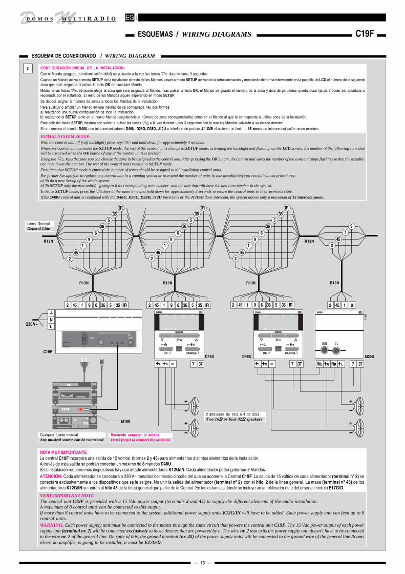
CONFIGURACIÓN INICIAL DE LA INSTALACIÓN:Con el Mando apagado (retroiluminación débil) se pulsarán a la vez las teclas / durante unos 3 segundos.Cuando un Mando activa el modo SETUP de la instalación el resto de los Mandos pasan a modo SETUP activando la retroiluminación y mostrando de forma intermitente en la pantalla de LCD el número de la siguientezona que será asignada al pulsar la tecla OK de cualquier Mando.Mediante las teclas / se puede elegir la zona que será asignada al Mando. Tras pulsar la tecla OK, el Mando se guarda el número de la zona y deja de parpadear quedándose fija para poder ser apuntada orecordada por el instalador. El resto de los Mandos siguen esperando en modo SETUP.Se deberá asignar el número de zonas a todos los Mandos de la instalación.Para sustituir o ampliar un Mando en una instalación ya configurada hay dos formas:a) realizando una nueva configuración de toda la instalación,b) realizando el SETUP tanto en el nuevo Mando (asignándole el número de zona correspondiente) como en el Mando al que le corresponda la última zona de la instalación.Para salir del modo SETUP, bastará con volver a pulsar las teclas / a la vez durante unos 3 segundos con lo que los Mandos volverán a su estado anterior.Si se combina el mando D48U con intercomunicadores D46U, D26D, D28D, J12U o interface de portero J11G/B el sistema se limita a 15 zonas de intercomunicación como máximo.
INITIAL SYSTEM SETUP:
With the control unit off (soft backlight) press keys / and hold down for approximately 3 seconds.
When one control unit activates the SETUP mode, the rest of the control units change to SETUP mode, activating the backlight and flashing, on the LCD screen, the number of the following zone thatwill be assigned when the OK button of any of the control units is pressed.
Using the / keys the zone you can choose the zone to be assigned to the control unit. After pressing the OK button, the control unit saves the number of the zone and stops flashing so that the installercan note down the number. The rest of the control units remain in SETUP mode.
First time that SETUP mode is entered the number of zones should be assigned to all installation control units.
For further Set-ups (i.e. to replace one control unit in a running system or to extend the number of units in one installation) you can follow two procedures:a) To do a new Set-up of the whole system.b) To SETUP only the new unit(s) –giving to it its corresponding zone number- and the unit that will have the last zone number in the system.
To leave SETUP mode, press the / keys at the same time and hold down for approximately 3 seconds to return the control units to their previous state.
If the D48U control unit is combined with the D46U, D26U, D28D, J12U intercoms or the J11G/B door intercom, the system allows only a maximum of 15 intercom zones.
NOTA MUY IMPORTANTELa central C19F incorpora una salida de 15 voltios (bornas 2 y 45) para alimentar los distintos elementos de la instalación.A través de esta salida se podrán conectar un máximo de 8 mandos D48U.Si la instalación requiere más dispositivos hay que añadir alimentadores K12G/IN. Cada alimentador podrá gobernar 8 Mandos.ATENCIÓN: Cada alimentador se conectará a 230 V~ tomados del mismo circuito del que se acomete la Central C19F. La salida de 15 voltios de cada alimentador (terminal nº 2) seconectará exclusivamente a los dispositivos que se le asigne. No unir la salida del alimentador (terminal nº 2) con el hilo 2 de la línea general. La masa (terminal nº 45) de losalimentadores K12G/IN se unirán al hilo 45 de la línea general que parte de la Central. En las estancias donde se incluye un amplificador éste debe ser el módulo E17G/D.
VERY IMPORTANT NOTEThe central unit C19F is provided with a 15 Vdc power output (terminals 2 and 45) to supply the different elements of the audio installation.A maximum of 8 control units can be connected to this output.If more than 8 control units have to be connected to the system, additional power supply units K12G/IN will have to be added. Each power supply unit can feed up to 8control units.
WARNING: Each power supply unit must be connected to the mains through the same circuit that powers the central unit C19F. The 15 Vdc power output of each powersupply unit (terminal nr. 2) will be connected exclusively to those devices that are powered by it. The wire nr. 2 that exits the power supply unit doesn’t have to be connectedto the wire nr. 2 of the general line. On spite of this, the ground terminal (nr. 45) of the power supply units will be connected to the ground wire of the general line.Roomswhere an amplifier is going to be installer, it must be E17G/D.

D MM U L T I R A D I OD O M O S
— 14 —
MANDO Y MÓDULO / CONTROL UNIT & MODULE D48U - M20UD48U - Mando estereofónico de 2 canales musicales con control digital de volumen, graves, agudos, balancey sonido espacial. Intercomunicador hasta 63 zonas, niñera-vigilancia y acceso al portero.
M20U - Módulo que permite conectar unos auriculares y la salida de audio (*) de una fuente musicalproporcionando un tercer canal al mando D48U.
El funcionamiento del producto se describe en el "Manual del usuario".
D48U - Stereophonic control unit for 2 music channels with digital control of volume, bass, trebble,balance and spatial sound. Intercom system for up to 63 zones, baby-surveillance and access to doorintercom.M20U - Module that allows headphones to be connected as well as the audio output (*) of a music sourceproviding the D48U control unit with a third channel.Our user's manual shows how to operate this product.
D48U - 2 CANALES DE SONIDO + INTERCOMUNICADOR / 2 AUDIO CHANNELS + INTERCOM
1
Alimentación V; I máx.
Potencia audio
Impedancia de los altavoces
Conector para auriculares
Conector para walkman®
Timer (apagado en)
ESPECIFICACIONES
Regulador de volumenVolume control
1138_A
Piloto CancelCancel lamp
1138_A
SPECIFICATIONS
Power supply V; Max I
Audio power
Speaker impedance
Headphones socket
Walkman® input
Timer (sleep time)
D48U M20U
15 V ; 330 mA 15 V ; 20 mA
1 W x 2
1÷2 x 16 • 4 x 32
16 ÷ 600 ΩΩΩΩΩ
0.9 V
sólo estéreo/stereo only
sensibilidad/sensitivity
Pulsador de encendido/apagado / OKON/OFF / OK button
VisualizadorDisplay
D48U
Pulsador Menu / PorteroMenu / Door opening button
ual
Pulsador / Cancel / Cancel button
Micrófono interno y receptor de infrarrojos.Cualquier Mando a distancia de 36 KHz.Internal microphone and IR receiver.Any remote control in range 36 KHz.
Piloto de encendidoON lamp
Piloto lamp
M20U - ENTRADA DE WALKMAN® + SALIDA DE AURICULARES / AUX INPUT + HEADPHONES OUTPUT
1
1144
Conector para auricularesHeadphones socket
M20U
Debe proceder de una salida de auricularesIt should come from a headphones output
Entrada para walkman® y PC (*)Aux input (*)
Programmable from 1" to 59"De 1" a 59" programable
Piloto de OKOK lamp
*

D MM U L T I R A D I OD O M O S
DESCRIPCION: Cuando la Fuente Musical disponga únicamente de salidas para auriculares se conectará a la Central mediante la Conexión T11N.
FUENTES MUSICALES QUE ADMITEN ESTE CONEXIONADO:- Walkman® (Discmans, Mini-Cadenas, Radio-Cassettes, etc.)
DESCRIPTION: If the only available output of the musical source is the headphones output, it should be connected to the Central unit usingthe T11N connector.
MUSICAL SOURCES COMPATIBLE WITH THIS CONNECTION:- Walkman® (Discman, mini HI-FI systems, radiocassetes...)
— 15 —
CONEXIONADO A SALIDA DE GRABACION (REC-OUT) / CONNECTION TO RECORD OUTPUT
DESCRIPCION: Es la adaptación ideal para los aparatos que dispongan de conectores para Grabación, ya que laseñal disponible en estas salidas no está afectada por los controles de volumen, tono, etc. del aparato, por lo que esconstante.
FUENTES MUSICALES QUE ADMITEN ESTE CONEXIONADO:- Equipos HI-FI modulares.- Algunas Mini-Cadenas y aparatos portátiles.
ATENCION: Utilicen esta conexión siempre que sea posible. Es la solución óptima.
DESCRIPTION: This is the ideal connection for those musical devices that have record outputs, becausethis signal is not affected by the volume and tone controls of the musical device and so it has a constantlevel.
MUSICAL SOURCES THAT SUPPORT THIS CONNECTION:- Modular HI-FI systems.- Some mini Hi-Fi systems and portable devices.
WARNING: Always use this connection, if possible. It is the best solution.
Derivación en los cables del magnetófono.Derivation of the tape recorder wiring.
CONECTORES DE MAGNETOFONOTAPE RECORDER CONNECTORS
T13N
LINEOUT
0052
Al magnetófonoTo tape recorder
0051
TAPEPLAY
IN
RECOUT
A la CentralTo Central unit
T14N
T13NT13N
TAPEPLAY
IN
RECOUT
A la CentralTo Central unit
0050
T15N
0053
SALIDA DE ALTAVOCESSPEAKERS OUTPUT
0054
_B
CONEXION DE FUENTES MUSICALES / MUSICAL SOURCES CONNECTION
1
EJEMPLOS DE CONEXIONADO CON DIFERENTES FUENTES MUSICALES / EXAMPLES OF CONNECTION FOR DIFFERENT MUSICAL SOURCES
T15N
T11N
T13N
0070
Entrada universal de audioUniversal audio input
AuricularesHeadphones
AltavocesSpeakers
Salidas de grabación o líneaLine or record outputs
CONEXIONES AUDIO AUDIO CONNECTIONS
T11N
SALIDA AURICULARES / HEADPHONES OUTPUT
T11N
T13N
SALIDA GRABACION / RECORD OUTPUT
LR
SALIDA AURICULARES / HEADPHONES OUTPUT
REC-OUTo
LINE-OUTo
LINEA
T13N
T15N
SALIDA ALTAVOCES / SPEAKERS OUTPUT
SALIDA GRABACION / RECORD OUTPUT
R
L
+ +RL
REC-OUT
Si el aparato dispone de Salida de Línea (LINE-OUT) o de Grabación (REC-OUT) utilícela con preferencia a la de auriculares o altavoces.If the musical device has a Line output or Record output, use it preferably instead of the loudspeakers or headphones output.
0335
_C
0335
_B
0335
_A
CONEXIONADO A SALIDA DE LINEA (LINE-OUT) / CONNECTION TO THE LINE SOCKET
DESCRIPCION: Es la adaptación a las Fuentes Musicales que disponen de conectores de salida de señal de bajo nivel (entre 0,3 y 2 voltios). Normalmente se utilizan conectores RCA yla señal disponible puede estar regulada por los controles de volumen, tono, etc. del aparato (caso de la disponible en algunos equipos HI-FI), o por el contrario ser constante como laproporcionada por Elementos HI-FI individuales (CD, Sintonizadores, etc.).
FUENTES MUSICALES QUE ADMITEN ESTE CONEXIONADO:- Elementos HI-FI independientes (CD, Sintonizadores, Magnetófonos, Videos HI-FI, etc.).- Algunas Mini-Cadenas y aparatos portátiles.
DECRIPTION: This is the way to connect those musical sources that have low level output connectors (signal between 0.3 and 2 volts). RCA connectors are tipicallyused. The available signal can be regulated with the volume and tone controls of the device (in some HI-FI systems) or, on the contrary, it can be constant like the signalprovided by some individual HI-FI elements (CD players, tuners...).
MUSICAL SOURCES THAT SUPPORT THIS CONNECTION:- Standalone HI-FI components (CD players, Tuners, Tape recorders, Hi-Fi videos, etc.)- Some mini Hi-Fi systems and portable devices..
CONEXIONADO A SALIDA DE AURICULARES (PHONES) / CONNECTION TO HEADPHONES OUTPUT
CONEXIONADO A SALIDAS DE ALTAVOZ / CONNECTION TO SPEAKERS OUTPUT
DESCRIPCION: Cuando la Fuente Musical disponga únicamente de salidas para altavoces exteriores se unirá la salida de altavoces a la Central medianteuna Conexión T15N.Posible problema: A algunos equipos se les pueden fundir los fusibles de protección al unir los terminales de masa (–) de los altavoces mediante la Conexión T15N.Solución: El módulo C13N elimina el problema de unión de las masas de altavoces ya que incorpora transformadores de aislamiento de audio.
FUENTES MUSICALES QUE ADMITEN ESTE CONEXIONADO:- Equipos Compactos, Mini-Cadenas, Portátiles y en general siempre que no exista Salida de Grabación, de Línea o de Auriculares.
DESCRIPTION: If the musical source only has outputs for external loudspeakers, then the loudspeakers output should be connected to theCentral unit using the T15N connection.Possible trouble: In some devices, the protector fuses can blow when the speakers ground terminals (–) are joined using the T15N connection.
Solution: The C13N module prevents this problem, using audio isolation transformers.
MUSICAL SOURCES THAT SUPPORT THIS CONNECTION:- Compact, mini HI-FI and portable systems; generally all the equipment without record or line outputs.
Walkman®
0334
T11N
230 V
A la CentralTo Central unit
Conector para alimentación exteriorConnector for external power supply
A la CentralTo Central unit
A la CentralTo Central unit
Alimentador C.C.DC power supply
Cuando el Equipo de Músicade problemas al unir las masasde ambas salidas de altavoces.If there is any problem atthe music system whenjoining the grounds of bothloudspeakers outputs.
USO DEL MODULO C13NUSE OF THE C13N MODULE

D MM U L T I R A D I OD O M O S
D42U
ONON
D41U
ON
D41U D42U
ON
— 16 —
MANDOS / CONTROL UNITS D41U - D42UMandos de 1 canal de sonido para sonorizar en mono (1 altavoz) o en stereo (2 altavoces) una habitación.Regulador de volumen digital. Tienen la potencia adecuada para una habitación pero si se desea aumentarlaañádase un Amplificador E17G. Protección contra equivocaciones de conexionado y cortocircuitos en el altavoz.
El funcionamiento del producto se describe en el "Manual del usuario".
1-channel Control unit to provide mono (1 speaker) or stereo (2 speakers) sound for a room. Digitalvolume regulation. Its power is suitable for one room, but if you want to increase it, you can addan E17G amplifier. Protected against mistaken connections and loudspeaker short-circuits.
Our user's manual shows how to operate this product.
D41U - 1 CANAL DE SONIDO MONO / 1 MONO AUDIO CHANNEL D42U - 1 CANAL DE SONIDO STEREO / 1 STEREO AUDIO CHANNEL
1
Alimentación V; I máx.
Potencia audio
Impedancia de los altavoces
Conector para auriculares
Conector para walkman®
Timer (apagado en)
ESPECIFICACIONES
2
D41U D42UHABITACION CON SONIDO STEREOROOM WITH STEREO SOUND
HABITACION CON SONIDO MONOROOM WITH MONO SOUND
2 45 5 35
2 altavoces de 16Ω o 4 de 32ΩTwo 16ΩΩΩΩΩ or four 32Ω Ω Ω Ω Ω speakers
D42U
0792
2 x 0.75 mm2
+
+
+ +
5
2
35
455
245
35
Altavoz 16 Ω16 ΩΩΩΩΩ speaker
2 x 0.75 mm2
2 45 5 35 +
D41U
+
Regulador de volumenVolume control
Salida para auriculares stereoStereo headphones socket
Entrada para walkman®Walkman® input
0790
Pulsador de ScanScan button
0789
Línea GeneralGeneral Line
SPECIFICATIONS
Power supply V; Max I
Audio power
Speaker impedance
Headphones socket
Walkman® input
Timer (sleep time)
D41U D42U
15 V ; 230 mA 15 V ; 330 mA
1.5 W 1.5 W x 2
1 x 16 ΩΩΩΩΩ • 2 x 32 ΩΩΩΩΩ 1÷2 x 16 ΩΩΩΩΩ • 4 x 32 ΩΩΩΩΩ
8 ÷ 600 ΩΩΩΩΩ
0.45 V
45 min.
sólo stereo/stereo only
sensibilidad/sensitivity
3
Selector mono/stereoMono/stereo selector
MONO
STEREO
1 altavoz1 speaker2 ó 4 altavoces2 or 4 speakers
MONO STEREOHILOS DE LA LINEA GENERAL
GENERAL LINE WIRES
Ref. cableCable ref.
R18N
R19N
4 1 —
6 1
Nº de hilosNr. of wires
0711
0791
Selector mono/stereoMono/stereo selector
Hilo de masa. Ver fig. 3Ground wire. See fig. 3
Conexión de altavocesSpeaker connection
Conexión a Línea GeneralGeneral Line connection
NOTA: Evite colocar el Mando al lado de un reguladorde luz para que las perturbaciones electromagnéticasque ocasionan no perjudiquen la calidad del sonido.El Mando dispone de un "hilo de masa" que, sujetándo-lo al chasis metálico mediante uno de los tornillos, ayudaa reducir las perturbaciones de los reguladores de luz.NOTE: If possible, avoid placing the Control unitnext to a light dimmer. The electromagnetic distur-bances that dimmers generate may affect soundquality. The Control unit has a ground wire that canbe connected to the metallic frame by one of thescrews to reduce these disturbances.
Pulsador de ScanScan button
Piloto de encendido/apagadoON/OFF lamp
Piloto de timerTimer lamp
D41U
Pulsador de encendido/apagadoON/OFF button
Piloto de encendido/apagadoON/OFF lamp
Pulsador de encendido/apagadoON/OFF button
Piloto de timerTimer lamp
ual
D42U

D MM U L T I R A D I OD O M O S
— 17 —
MANDOS / CONTROL UNITS D45U - D44UMandos de 2 canales de sonido para sonorizar en mono (1 altavoz) o en stereo (2 altavoces) una habitación.Volumen con "loudness" para ecualizar el sonido según el nivel de escucha. Tienen la potencia adecuada parauna habitación pero si se desea aumentarla añádase un Amplificador E17G. Protección contra equivocacionesde conexionado y cortocircuitos en el altavoz.
El funcionamiento del producto se describe en el "Manual del usuario".
2-channel Control unit to provide mono (1 speaker) or stereo (2 speakers) sound for a room.Volume with loudness to equalize the sound depending on the listening level. Its power is suitablefor one room, but if you want to increase it, you can add an E17G amplifier. Protected againstmistaken connections and loudspeaker short-circuits.
Our user's manual shows how to operate this product.
D45U - 2 CANALES DE SONIDO MONO / 2 MONO AUDIO CHANNELS D44U - 2 CANALES DE SONIDO STEREO / 2 STEREO AUDIO CHANNELS
1
Alimentación V; I máx.
Potencia audio
Impedancia de los altavoces
Conector para auriculares
Conector para walkman®
Realce del "loudness"
Timer (apagado en)
ESPECIFICACIONES
D44U
Sólo D44UOnly D44U
2.12
D45U D44UHABITACION CON SONIDO STEREOROOM WITH STEREO SOUND
HABITACION CON SONIDO MONOROOM WITH MONO SOUND
2 45 5 35 6 36
2 altavoces de 16Ω o 4 de 32ΩTwo 16ΩΩΩΩΩ or four 32Ω Ω Ω Ω Ω speakers
D44U
0716
2 x 0.75 mm2
+
+
+ +
5
2
35
45
36
5
245
366
35
Altavoz 16 Ω16 ΩΩΩΩΩ speaker
2 x 0.75 mm2
2 45 5 35 6 36 +
D45U
+
Regulador de volumen con loudnessVolume control (with loudness)
Salida para auriculares stereoStereo headphones socket
Entrada para walkman®Walkman® input
Piloto de timerTimer lamp
0712
Pulsador de encendido/apagadoON/OFF button
Pulsador de ScanScan button
Selector de canalesChannel selector
0715
TapitaCover
Línea GeneralGeneral Line
6
SPECIFICATIONS
Power supply V; Max I
Audio power
Speaker impedance
Headphones socket
Walkman® input
Loudness equalization
Timer (sleep time)
D45U D44U
15 V ; 155 mA 15 V ; 300 mA
1.5 W 1.5 W x 2
1 x 16 Ω Ω Ω Ω Ω • 2 x 32 ΩΩΩΩΩ 1÷2 x 16 Ω Ω Ω Ω Ω • 4 x 32 ΩΩΩΩΩ
8 ÷ 600 ΩΩΩΩΩ
0.45 V
en graves/for bass: + 5 dB
30 min.
sólo stereo/stereo only
sensibilidad/sensitivity
3
Selector mono/stereoMono/stereo selector
MONO
STEREO
1 altavoz1 speaker2 ó 4 altavoces2 or 4 speakers
MONO STEREO
HILOS DE LA LINEA GENERALGENERAL LINE WIRES
Ref. cableCable ref.
R18N
R19N
R19N
R15N
4 1 —
6 1
6 2 —
8 2
Nº de hilosNr. of wires
0711
canal / channel 2
0714
Selector mono/stereoMono/stereo selector
Hilo de masa. Ver fig. 3Ground wire. See fig. 3
Conexión de altavocesSpeaker connection
Conexión a Línea GeneralGeneral Line connection
NOTA: Evite colocar el Mando al lado de un reguladorde luz para que las perturbaciones electromagnéticasque ocasionan no perjudiquen la calidad del sonido.El Mando dispone de un "hilo de masa" que, sujetándo-lo al chasis metálico mediante uno de los tornillos, ayudaa reducir las perturbaciones de los reguladores de luz.NOTE: If possible, avoid placing the Control unitnext to a light dimmer. The electromagnetic distur-bances that dimmers generate may affect soundquality. The Control unit has a ground wire that canbe connected to the metallic frame by one of thescrews to reduce these disturbances.
ual

D MD O M O S M U L T I R A D I O
— 18 —
MANDO + INTERCOM / CONTROL UNIT + INTERCOM D46UEl Mando D46U, además de Sonido Ambiental, permite la comunicación entre habitaciones y con el porteroautomático. Las funciones más usuales son accesibles con la tapa cerrada y el resto tienen sus controles bajola tapa. El amplificador de audio incorporado de 3 W tiene la potencia adecuada para uso doméstico, si precisamás potencia añada un amplificador E17G.
El funcionamiento del producto se describe en el "Manual del usuario".
The Control unit D46U, besides background sound, allows intercom, between rooms and with the doorentry system. The most usual functions can be operated without opening the cover, and the rest of themhave their controls under this cover. The built-in 3 Watt audio amplifier has the appropiate power forhome applications, but if more power is required an E17G amplifier can be installed.
Our user's manual shows how to operate this product.
2.12
D46UHABITACION CON SONIDO STEREO + INTERCOMROOM WITH STEREO SOUND + INTERCOM
Alimentación V; I máx.
Potencia audio
Impedancia de los altavoces
Conector para auriculares
Tonos graves y agudos
Realce del "loudness"
Timer (apagado en)
ESPECIFICACIONES SPECIFICATIONS
Power supply V; Max I
Audio power
Speaker impedance
Headphones socket
Bass & treble tones
Loudness equalization
Timer (sleep time)
D46U
15 V , 350 mA
1.5 W x 2
1÷2 x 16 Ω Ω Ω Ω Ω • 4 x 32 ΩΩΩΩΩ
sólo stereo/stereo only: 8 ÷ 600 ΩΩΩΩΩ
± 10 dB
en graves/for bass: + 5 dB
30 min.
3
2 altavoces de 16Ω o 4 de 32ΩTwo 16ΩΩΩΩΩ or four 32Ω Ω Ω Ω Ω speakers
D46U
0718
Selector mono/stereoMono/stereo selector
MONO
STEREO
1 altavoz1 speaker2 ó 4 altavoces2 or 4 speakers
MONO STEREO HILOS DE LA LINEA GENERALGENERAL LINE WIRES
Ref. cableCable ref.
R19N
R15N
6 1
8 2
Nº de hilosNr. of wires
0711
2
356
455
36
91
2 45 5 35 6 36 1 9 + +
2 x 0.75 mm2
+
+
Línea GeneralGeneral Line
1
TRE
0713
Salida para auriculares stereoStereo headphones socket
Selector de funcionesFunction selector
No molestarDo not disturb
EscucharListen
Piloto de timerTimer lamp
Graves y agudosBass & treble
Regulador de volumen con loudnessVolume control (with loudness)
Niñera-vigilanciaBaby sitting-monitoring
Selector de canalesChannel selector
0717
0719
Selector mono/stereoMono/stereo selector
HablarTalk
TapitaCover
Conexión a Línea GeneralGeneral Line connection
Hilo de masa. Ver fig. 3Ground wire. See fig. 3
Conexión de altavocesSpeaker connection
D46U - 2 CANALES DE SONIDO STEREO + INTERCOM / 2 STEREO AUDIO CHANNELS + INTERCOM
NOTA: Evite colocar el Mando al lado de un reguladorde luz para que las perturbaciones electromagnéticasque ocasionan no perjudiquen la calidad del sonido.El Mando dispone de un "hilo de masa" que, sujetándo-lo al chasis metálico mediante uno de los tornillos, ayudaa reducir las perturbaciones de los reguladores de luz.NOTE: If possible, avoid placing the Control unitnext to a light dimmer. The electromagnetic distur-bances that dimmers generate may affect soundquality. The Control unit has a ground wire that canbe connected to the metallic frame by one of thescrews to reduce these disturbances.
Pulsador de encendido/apagadoON/OFF button
Pulsador de ScanScan button
Abrepuerta del portero automáticoDoor opening
canal / channel 2
CENTRAL
C11F-C17F-C12F 1 - 2 - 4
C18F 1
C16F 2
C14F 2 - 4
FUNCIONES DEL MANDO D46UD46U FUNCTIONS
D46U
ual
D MM U L T I R A D I OD O M O S
— 19 —
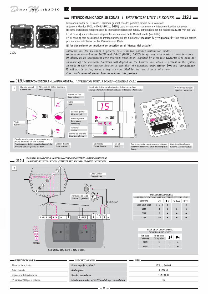
INTERCOMUNICADOR 15 ZONAS / INTERCOM UNIT 15 ZONES J12U
2.12
J12UEN INSTALACION DOMOS. HABITACION CON SONIDO STEREO + INTERCOM 15 ZONASIN A DOMOS SYSTEM. ROOM WITH STEREO SOUND + 15-ZONE INTERCOM
Alimentación V; I máx.
Potencia audio
Impedancia de los altavoces
Nº máximo J12U por Instalación
ESPECIFICACIONES SPECIFICATIONS
Power supply V; Max I
Audio power
Speaker impedance
Maximum number of J12U modules per installation
J12U
15 V , 140 mA
0.12 W x 2
1÷2 x 16 ΩΩΩΩΩ
15
D44U (D41U, D42U, D45U) + J12U + 1802/..
0763
STEREO
HILOS DE LA LINEA GENERALGENERAL LINE WIRES
Ref. cableCable ref.
R19N
R15N
6 1
8 2
Nº de hilosNr. of wires
2
356
455
36
2 45 5 35 6 36 + +
2 x 0.75 mm2
+
Línea GeneralGeneral Line
1
0761
Selector de funcionesFunction selector
No molestarDo not disturb
Llamada generalGeneral call
Niñera-vigilanciaBaby sitting-monitoring
EscucharListen
HablarTalk
Visualizador de la zona seleccionada o de la zona que llamaDisplay which shows the selected zone or the zone which calls.
Selector de zonaZone selector
0760
0762
Pulsador para terminar la comunicación con elportero automático sin abrir la puertaPush button to finish comunication with thedoor unit without opening the door.
TapitaCover
Conexión a Línea GeneralGeneral Line connection
Conexión de altavocesSpeaker connection
J12U - INTERCOM 15 ZONAS + LLAMADA GENERAL / INTERCOM UNIT 15 ZONES + GENERAL CALL
Llamada generalGeneral call
Selector de zonaZone selector
Abrepuerta del portero automáticoDoor opening
canal / channel 2
+ + + +2 45 9 1
19
Set-upSet-up
+
CENTRAL
C11F-C17F-C12F 1 - 2 - 4
C18F 1
C16F 2
C14F 2 - 4
TABLA DE PRESTACIONESAVAILABLE FUNCTIONS WITH DIFFERENT CENTRAL UNITS
Puente para quitar cuando se use amplificadorJumper to be removed when an amplifier isin use.
2 altavoces de 16 ΩTwo 16Ω Ω Ω Ω Ω speakers
Intercomunicador de 15 zonas + llamada general con dos posibles modos de instalación:a) junto a Mandos D42U y D44U (D41U, D45U) para instalaciones con música + intercomunicación por zonas,b) como instalación independiente de intercomunicación por zonas, alimentados con un módulo K12G/IN (ver pág. 35).
En el caso a) las prestaciones disponibles dependerán de la Central usada (ver tabla).En el caso b) sólo se dispone de intercomunicación; las funciones "escucha" y "vigilancia" no estarán activasporque son controladas por las Centrales con Radio.
El funcionamiento del producto se describe en el "Manual del usuario".
Intercom unit for 15 zones + general call, with two possible installation modes:a) Next to control units D42U and D44U (D41U, D45U) in systems with music + zone intercom.b) Alone, as an independent zone intercom installation, supplied by a module K12G/IN (see page 35).
In mode a) The available functions will depend on the Central unit which is present in the system.In mode b) Only the intercom function is available. The functions "baby-sitting" and "surveillance"
will not be active, because they are controlled by the central units with tuner.
Our user's manual shows how to operate this product.
J12U
ual

D MM U L T I R A D I OD O M O S
1.- Pulsar la tecla "set-up" en un Intercomunicador y los visualizadores de todos ellos indicarán:
2.- A continuación ir a la habitación elegida como nº 2 y presionar el pulsador "+"
El visualizador de ese Intercomunicador indicará: 0202020202Si queremos que un Intercomunicador tenga la capacidad de contestar a las llamadas, sin pulsar tecla alguna (manos libres), pulsar ahora la tecla selector de funcionesy se iluminará el piloto " ". Si pulsamos de nuevo, la función se desactivará.Repetir este paso en el resto de las habitaciones siguiendo un orden correlativo (3, 4, 5...), sin olvidar ninguna.
3.- Cuando hayamos acabado con todas las habitaciones presionaremos el pulsador de set-up de cualquier Intercomunicador para finalizar el proceso. Los visualizadoresse apagarán.
RESET: Si alguno de los Intercomunicadores J12U o toda la instalación presenta un funcionamiento anormal se puede reinicializar el sofware (reset) apagando la(s)Central(es) durante 2 minutos y volviendo a encenderlas.
1.- Press the key “set-up” in any intercom unit, and the displays of every J12U will show:
2.- Then, go to the room which you want to be the zone nr. 2, and press the button "+" of the J12U in that room.The display of that J12U will show: 0202020202If you want that an intercom unit has the possibility to answer to the calls without pressing any button (function: “hands-free”), press now the functionselector key and the icon “ “ will light. Another press would turn the icon off and disable this function.Repeat this process for the rest of the rooms, always within a correlative order (3, 4, 5…) without forgetting anyone.
3.- When you have finished with all the rooms, you must press the set-up button of any intercom unit to finish the set-up. The displays will turn off.
RESET: If any of the intercom units J12U -or the whole system- shows an abnormal working order, it is possible to reset the software by turning thecentral unit(s) off during two minutes.
EXCEPCION: Si en la instalación conviven Intercomunicadores J12U con Mandos D26D o D46Ureserve la zona nº 1 para los Mandos. Asigne zonas a los Intercomunicadores J12U empezandopor la nº 2, pulsando el botón "+".
— 20 —
J12UCON AMPLIFICADOR DE 20 WINSTALLATION WITH 20 W AMPLIFIER
4
+ ++ +L +R
2
1
459
+ + + +2 45 9 1
E17G/DJ12U
Línea GeneralGeneral Line
230 V~
2 45
0767
Conexión de altavoces.Ver hoja del amplificador E17GLoudspeaker connectionSee info. on E17G
ASIGNACION DE ZONAS / ZONE SET-UP J12U
The two digits indicate the zonenumber assigned to that Controlunit. 010 10 10 10 1
0 10 10 10 10 1
NOTE: If Control units D26D or D46U are going to be installed together with J12U, theintercom zone nr. 1 must be reserved for D26D and D46U. The zone set-up must be startedfrom zone nr. 2, by pressing the button "+".
Los dígitos indican el número dezona que tiene asignado ese Inter-comunicador.
Quitar el puente para ampli-ficador trasero.Remove the rear jumper foramplifier.
J12UINSTALACION CON INTERCOM 15 ZONAS (sin música ni Central)ONLY INTERCOM SYSTEMS WITHOUT CENTRAL UNIT
3
452 STAND-BY19 LN
15 V 1.5 A max. GE K12G/INPower SupplyAlimentador
Made in E.U. ± 10% 50/60 Hz
2
1
459
+ + + +2 45 9 1
J12U
Línea GeneralGeneral Line
+
245
1
9
0766
K12G/IN (ver pág. 35/see page 35)
0.75 mm2
Hasta 15 intercom J12UUp to 15 units J12U
R18N R18N
230 V~
HILOS DE LA LINEA GENERALGENERAL LINE WIRES
Ref. cableCable ref.
R18N 4 —
Nº de hilosNr. of wires
Los colores de los hilos 1 y 9 no coincidenThe colours of wires 1 and 9 are not the same inthe cable and in the Control Unit's terminal block.
NOTA: No disponibles las funciones"escucha" y "niñera"NOTE: The "surveillance" and"baby sitting" functions are notavailable in this installation style.
16Ω
ual
D MM U L T I R A D I OD O M O S
— 21 —
2.12
D25D
D25D
35
545
2
+Altavoz 16 Ω16 ΩΩΩΩΩ speaker
2 x 0.75 mm2
R18N
+2 45 5 35
0619
_A
35
D24D
2 45 5 35 + +
2 x 0.75 mm2
+
+
545
2
2 altavoces de 16Ω o 4 de 32ΩTwo 16ΩΩΩΩΩ or four 32Ω Ω Ω Ω Ω speakers
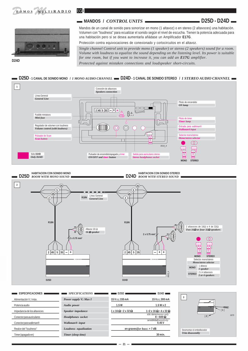
Selector mono/stereoMono/stereo selector
MONO
STEREO
1 altavoz1 speaker2 ó 4 altavoces2 or 4 speakers
MONO STEREO
D24D
R18N
MANDOS / CONTROL UNITS D25D - D24DMandos de un canal de sonido para sonorizar en mono (1 altavoz) o en stereo (2 altavoces) una habitación.Volumen con "loudness" para ecualizar el sonido según el nivel de escucha. Tienen la potencia adecuada parauna habitación pero si se desea aumentarla añádase un Amplificador E17G.
Protección contra equivocaciones de conexionado y cortocircuitos en el altavoz.
Single channel Control unit to provide mono (1 speaker) or stereo (2 speakers) sound for a room.Volume with loudness to equalize the sound depending on the listening level. Its power is suitablefor one room, but if you want to increase it, you can add an E17G amplifier.
Protected against mistaken connections and loudspeaker short-circuits.
D25D - 1 CANAL DE SONIDO MONO / 1 MONO AUDIO CHANNEL D24D - 1 CANAL DE SONIDO STEREO / 1 STEREO AUDIO CHANNEL
1
Alimentación V; I máx.
Potencia audio
Impedancia de los altavoces
Conector para auriculares
Conector para walkman®
Realce del "loudness"
Timer (apagado en)
SPECIFICATIONS
Power supply V; Max I
Audio power
Speaker impedance
Headphones socket
Walkman® input
Loudness equalization
Timer (sleep time)
D25D D24D 3
Desmontar el embellecedorTrim disassembly
[ 2 ]
[ 1 ]
0075
15 V ; 155 mA 15 V ; 300 mA
1.5 W 1.5 W x 2
1 x 16 ΩΩΩΩΩ • 2 x 32 ΩΩΩΩΩ 1÷2 x 16 ΩΩΩΩΩ • 4 x 32 ΩΩΩΩΩ
8 ÷ 600 ΩΩΩΩΩ
0.45 V
en graves/for bass: + 7 dB
30 min.
ESPECIFICACIONES
sólo stereo/stereo only
sensibilidad/sensitivity
HABITACION CON SONIDO STEREOROOM WITH STEREO SOUND
HABITACION CON SONIDO MONOROOM WITH MONO SOUND
Sólo D24DOnly D24D
Piloto de encendidoON lamp
Selector mono/stereoMono/stereo selector
Entrada para walkman®Walkman® input
Pulsador de encendido/apagado y timerON/OFF and timer button
Salida para auriculares stereoStereo headphones socket
Regulador de volumen con loudnessVolume control (with loudness)
Piloto de timerTimer lamp
Pulsador de ScanScan button
2 45 5 35 +Fusible miniaturaMini fuse
Línea GeneralGeneral Line
Conexión de altavocesSpeakers connection
R18NLínea GeneralGeneral Line
0616_A
D24D
MONO STEREO
ual
D MM U L T I R A D I OD O M O S
45
2
— 22 —
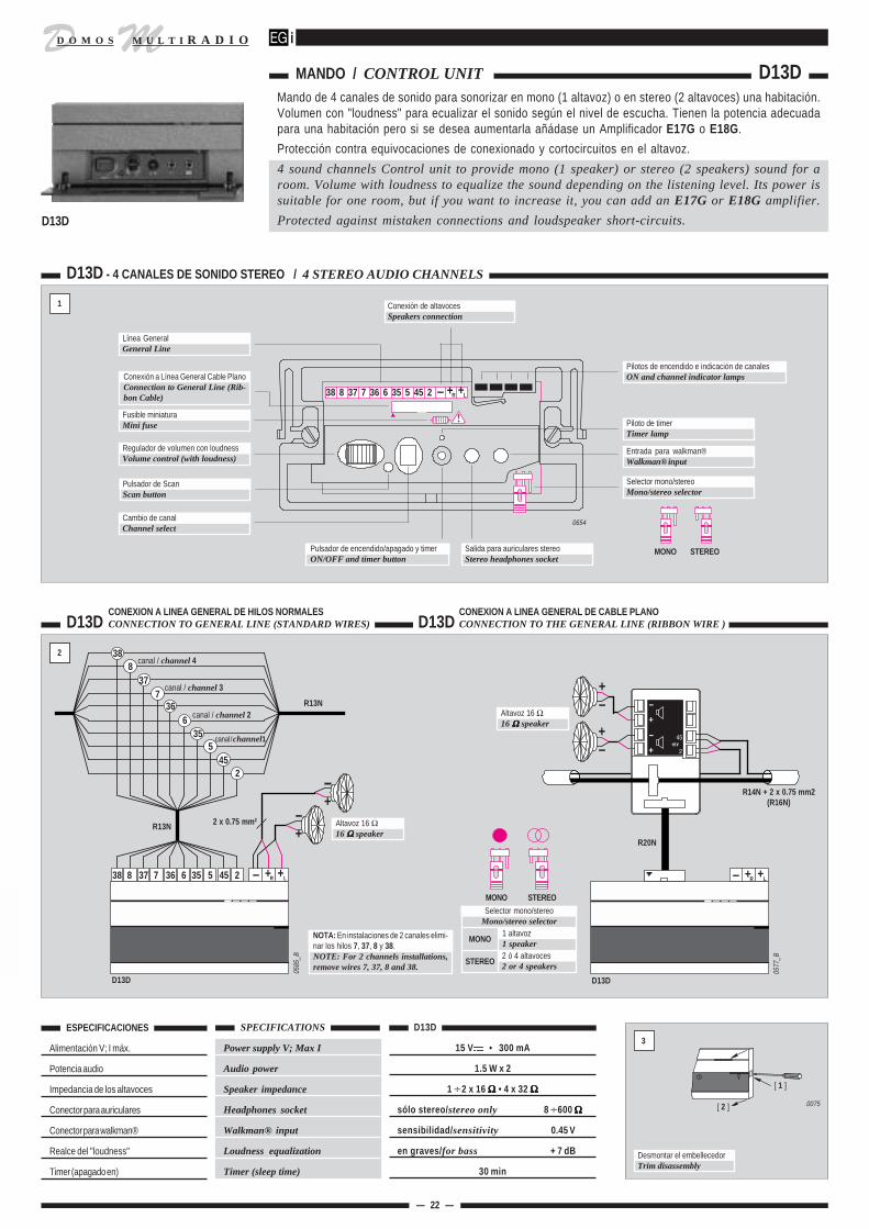
MANDO / CONTROL UNIT D13DMando de 4 canales de sonido para sonorizar en mono (1 altavoz) o en stereo (2 altavoces) una habitación.Volumen con "loudness" para ecualizar el sonido según el nivel de escucha. Tienen la potencia adecuadapara una habitación pero si se desea aumentarla añádase un Amplificador E17G o E18G.
Protección contra equivocaciones de conexionado y cortocircuitos en el altavoz.
4 sound channels Control unit to provide mono (1 speaker) or stereo (2 speakers) sound for aroom. Volume with loudness to equalize the sound depending on the listening level. Its power issuitable for one room, but if you want to increase it, you can add an E17G or E18G amplifier.
Protected against mistaken connections and loudspeaker short-circuits.
D13D - 4 CANALES DE SONIDO STEREO / 4 STEREO AUDIO CHANNELS
1
+
0654
38 8 37 7 36 6 35 5 45 2 +R L
Pilotos de encendido e indicación de canalesON and channel indicator lamps
Selector mono/stereoMono/stereo selector
Entrada para walkman®Walkman® input
Pulsador de encendido/apagado y timerON/OFF and timer button
Salida para auriculares stereoStereo headphones socket
Cambio de canalChannel select
Regulador de volumen con loudnessVolume control (with loudness)
Línea GeneralGeneral Line
Conexión de altavocesSpeakers connection
Fusible miniaturaMini fuse Piloto de timer
Timer lamp
Pulsador de ScanScan button
MONO STEREO
ESPECIFICACIONES
Alimentación V; I máx.
Potencia audio
Impedancia de los altavoces
Conector para auriculares
Conector para walkman®
Realce del "loudness"
Timer (apagado en)
SPECIFICATIONS
Power supply V; Max I
Audio power
Speaker impedance
Headphones socket
Walkman® input
Loudness equalization
Timer (sleep time)
D13D 3
Desmontar el embellecedorTrim disassembly
[ 2 ]
[ 1 ]
0075
15 V • 300 mA
1.5 W x 2
1 ÷ 2 x 16 Ω Ω Ω Ω Ω • 4 x 32 ΩΩΩΩΩ
sólo stereo/stereo only 8 ÷ 600 ΩΩΩΩΩ
sensibilidad/sensitivity 0.45 V
en graves/for bass + 7 dB
30 min
D13DCONEXION A LINEA GENERAL DE HILOS NORMALESCONNECTION TO GENERAL LINE (STANDARD WIRES) D13D
CONEXION A LINEA GENERAL DE CABLE PLANOCONNECTION TO THE GENERAL LINE (RIBBON WIRE )
2.12
0577
_B
+R L+
D13D
Altavoz 16 Ω16 ΩΩΩΩΩ speaker
+
+
R14N + 2 x 0.75 mm2(R16N)
R20N
0585
_B
38 8 37 7 36 6 35 5 45 2 +R L+
R13N
+
+2 x 0.75 mm2
R13N
2
535
6 canal / channel 236
7canal / channel 3
378
canal / channel 438
45
D13D
NOTA: En instalaciones de 2 canales elimi-nar los hilos 7, 37, 8 y 38.NOTE: For 2 channels installations,remove wires 7, 37, 8 and 38.
Altavoz 16 Ω16 ΩΩΩΩΩ speaker
Selector mono/stereoMono/stereo selector
MONO
STEREO
1 altavoz1 speaker2 ó 4 altavoces2 or 4 speakers
MONO STEREO
D13D
Conexión a Línea General Cable PlanoConnection to General Line (Rib-bon Cable)
canal / channel1
al

D MM U L T I R A D I OD O M O S
— 23 —
D26D
2.12
MANDO + INTERCOM / CONTROL UNIT + INTERCOM D26D
ESPECIFICACIONES
Alimentación V; I máx.
Potencia audio
Impedancia de los altavoces
Conector para auriculares
Tonos graves y agudos
Timer (apagado en)
SPECIFICATIONS
Power supply V; Max I
Audio power
Speaker impedance
Headphones socket
Bass & treble tones
Timer (sleep time)
D26D 3
[ 2 ]
[ 1 ]
15 V , 325 mA
1.5 W x 2
1 ÷ 2 x 16 Ω Ω Ω Ω Ω • 4 x 32 ΩΩΩΩΩ
sólo stereo/stereo only 8 ÷ 600 ΩΩΩΩΩ
± 10 dB
40 min
Desmontar el embellecedorTrim disassembly
CONEXION A LINEA GENERAL DE HILOS NORMALESCONNECTION TO GENERAL LINE (STANDARD WIRES)
D26D
0727
D26D - 2 CANALES DE SONIDO STEREO + INTERCOM / 2 STEREO AUDIO CHANNELS + INTERCOM
1
Piloto indicador de timerTimer lamp
0075
R15N+
+
+ +R L–9 1 36 6 35 5 45 2
2 altavoces de 16 Ωo 4 de 32 ΩTwo 16 ΩΩΩΩΩ orfour 32 ΩΩΩΩΩ speakers
91
366
5
245
35
0726
9 1 36 6 35 5 45 2 – + +R L
Pilotos indicadores de tonos (graves/agudos)Bass/Treble lamps
Piloto y pulsador de Scan y abrepuertaScan and Door opening lamp and button
Piloto y pulsador de cambio de canalesChannel selector lamp and button
Piloto y pulsador de encendido/apagadoON/OFF lamp and button
Salida de auricularesHeadphones socket
Micrófono internoInternal microphone
Pulsadores para regular el volumenRaise and lower volume buttons
Conexión de altavocesSpeakers connection
Conexión a Línea GeneralConnection to General Line
Pulsador selector de funcionesFunction selector
Pilotos indicadores de canal seleccionadoSelected channel lamps
Selector mono/stereoMono/stereo selector
canal / channel 2
Línea GeneralGeneral Line
SELECTOR STEREOSTEREO SELECTOR
0728
SELECTOR MONOMONO SELECTOR
HILOS DE LA LINEA GENERALGENERAL LINE WIRES
Ref. cableCable ref.
R19N
R15N
6 1
8 2
Nº de hilosNr. of wires
Piloto y pulsador para hablarTalk lamp and button
Pilotos indicadores de "niñera-vigilancia", "escu-cha" y "no molestar""Baby Sitting", "Listening" and "do notdisturb" lamps
El Mando D26D, además de Sonido Ambiental, permite la comunicación entre habitaciones y con elportero automático. Las funciones más usuales son accesibles con la tapa cerrada y el resto tienen suscontroles bajo la tapa. El amplificador de audio incorporado de 3 W tiene la potencia adecuada para usodoméstico, si precisa más potencia añada un amplificador E17G.
El funcionamiento del producto se describe en el "Manual del usuario".
The Control unit D26D, besides background sound, allows intercom, between rooms and with thedoor entry system. The most usual functions can be operated without opening the cover, and therest of them have their controls under this cover. The built-in 3 Watt audio amplifier has theappropiate power for home applications, but if more power is required an E17G amplifier canbe installed.
Our user's manual shows how to operate this product.
CENTRAL
C11F-C17F-C12F 1 - 2 - 4
C18F 1
C16F 2
C14F 2 - 4
FUNCIONES DEL MANDO D46UD26D FUNCTIONS
D26D
ual

D MM U L T I R A D I OD O M O S
— 24 —
MANDO MULTISERVICIO / MULTISERVICE CONTROL UNIT D28D
ESPECIFICACIONES
Alimentación continua
Consumo: apagado / encendido / máx. potencia
Potencia de sonido
Altavoces
Auriculares
SPECIFICATIONS
DC Power supply
Consumption: off / on / max. power
Sound power
Speakers
Headphones
15 V
87 mA 158 mA 370 mA
1.5 W x 2
1 ÷ 2 x 16 ΩΩΩΩΩ; 4 x 32 ΩΩΩΩΩ
sólo stereo/only stereo 8 ÷ 600 ΩΩΩΩΩ
D28D 2
Desmontar el embellecedorTrim disassembly 0075
[ 2 ]
[ 1 ]
D28D - MANDO MULTISERVICIO / MULTISERVICE CONTROL
1
0641
Resistencia fusibleFuse
Regleta de conexión de altavocesSpeaker terminal block
Línea General con cable planoGeneral line with ribbon wire
Puente de selección mono/stereoJumper for stereo/mono selection
VISTA POSTERIOR / REAR VIEW
0140
_A
STEREO MONO
PUENTE DE SELECCION MONO/STEREOJUMPER FOR STEREO/MONO SELECTION
REGLETA DE CONEXION DE ALTAVOCESSPEAKER TERMINAL BLOCK
+ + –R L
0611
_B
+R +L
++Anote los nombres de las habitaciones en el nº de zona correspon-diente de la etiqueta y adhiérala en el Mando.Write down the name of the rooms next to each correspondingzone number and stick the label on the Control unit.
0332
_F5A
Micrófono internoInternal microphone
Pulsador selector de zonasZone selector button
Piloto de timerTimer lamp
Pulsadores para subir y bajar el volumenVolume setting buttons
Piloto luminoso de la función niñera-vigilanciaBaby sitting-monitoring indicator lamp
Piloto luminoso de la función escucharListening indicator lamp
Piloto luminoso de la función hablarTalking indicator lamp
Pulsador selector de funcionesFunction selector
Piloto luminoso de la función no molestarDo Not Disturb indicator lamp
Pulsador de scanScan button
Receptor de infrarrojos IRIR receiver
Conector para auriculares stereoStereo headphones socket
Pulsador de encendido/apagado y timerOn/Off and Timer button
VisualizadoresDisplays
Pulsador de asignación de zonas o set-upZone assign or set-up button
Indicadores de canal de sonidoSound channel indicators
0594
Piloto de despertadorAlarm clock function lamp
Piloto de portero automáticoDoor entry system lamp
Pulsador de despertador / abrepuertaAlarm clock / Open door button
Pilotos indicadores de AM/PMAM/PM indicator lamps
VISTA FRONTAL / FRONT VIEW
Pulsador selector de canalesChannel selector
Pulsador para hablarTalk button
D28D
CENTRAL 12 : 3012 : 3012 : 3012 : 3012 : 30
C11F-C17F-C12F 1 - 2 - 4
C18F 1
C16F 2
C14F 2 - 4
FUNCIONES DEL MANDO D28DD28D FUNCTIONS
El Mando D28D, además de disponer de 4 canales de música stereo con controles de tonos (graves yagudos), volumen, balance, scan, timer y conector de auriculares, proporciona servicio de intercomuni-cación con llamada general o independiente para 15 habitaciones. También dispone de baby-phonemúltiple, vigilancia sonora, función "no molestar" y posibilidad de contestar a una llamada sin pulsarteclas (manos libres). El reloj despertador incorporado y la capacidad de interconexión y manejo delportero automático completan las funciones del D28D. Todas las funciones se pueden manejar tambiénmediante el Mando a distancia M13N.
El funcionamiento del producto se describe en el "Manual del usuario".
The Control unit D28D provides an intercom. function with generall call or zone call up to 15zones in adition to bass and treble control, volume setting, balance, scan, timer, headphones socketand 4 stereo music channels. It is also equiped with multiple baby-phone, monitoring, "do notdisturb" function, and "hands-free" operation (call answering without pushing any button). TheD28D can be connected to a door entry system and has a built-in alarm clock . All the functionsare available from the M13N remote control.
Our user's manual shows how to operate this product.
ual

D MM U L T I R A D I OD O M O S
1.- En la etiqueta adhesiva, que viene incluida en cada Mando, haga la lista de las habitaciones al lado del número correspondiente.2.- Desmontar el embellecedor del Mando nº 1 para acceder al pulsador de asignación de zonas o set-up.3.- Pulsar la tecla de set-up e inmediatamente los visualizadores de todos los Mandos indicarán:
4.- A continuación ir a la habitación elegida como nº 2 y presionar el pulsador selector de zonas El visualizador de ese Mando indicará: .202.202.202.202.202Si queremos que un Mando tenga la capacidad de contestar a las llamadas, sin pulsar tecla alguna (manos libres), pulsar ahora la tecla y se iluminaráel piloto de la función hablar. Si pulsamos de nuevo, la función se desactivará.Repetir este paso en el resto de las habitaciones siguiendo un orden correlativo (3, 4, 5...), sin olvidar ninguna.
5.- Cuando hayamos acabado con todas las habitaciones volveremos de nuevo al Mando nº 1 y presionaremos el pulsador de set-up para finalizar el proceso.A continuación, los visualizadores indicarán la hora (si tenemos conectada una Central C14F).
6.- Con un Mando a distancia M13N ajuste al gusto de su cliente los tonos graves y agudos y el balance del sonido. Con estos ajustes obtendrá un sonido degran calidad al ecualizar la respuesta de los altavoces.
RESET: Si alguno de los Mandos D28D o toda la instalación presenta un funcionamiento anormal se puede reinicializar el sofware (reset) apagando la(s)Central(es) durante 2 minutos y volviendo a encenderlas.
1.- In the adhesive label included in each Control write down the list of the rooms next to each corresponding zone number.2.- Remove the trim of the Control unit number 1 to access to the set-up button.3.- Press the setup key and the displays of all the Control units will show:
4.- Go to the room selected as number 2 and press the zone selector buttonThe display of that Control unit will show: .202.202.202.202.202If you want "hands free" answering to be available in a Control unit, press now and the Talk lamp will light. If you press this buttonagain, the function will be disabled.Repeat this step in the rest of the rooms, following a correlative order without forgetting anyone (3, 4, 5...).
5.- After repeating step 4 in every room, turn back again to Control unit number 1 and press the setup button. Then the displays will showthe time (if you have a C14F Central unit).
6.- With a M13N remote control adjust the sound balance, bass and treble. With this adjustments, you will get a high quality sound.
RESET: If any of the D28D Control units or the whole installation shows any kind of malfunction, the system software can be resetted byswitching the Central unit(s) off for a couple of minutes.
— 25 —
D28DCONEXION A LINEA GENERAL DE HILOS NORMALESCONNECTION TO GENERAL LINE WITH STANDARD WIRES
2.11
45
215 V
Cable plano de 20 víasRibbon wire 20 waysR20N
R16N = R14N + 2 x 0.75 mm2
+
+Altavoz de 16 Ω16 ΩΩΩΩΩ speaker
R16N R16N
D28D
0622
D28D
0621
I21D
8
376
738
36
245
535
91
ASIGNACION DE ZONAS / ZONE SET-UP D28D
+ + –
+ +
12 hilos12 wiresR13N
Cable plano de 20 víasRibbon wire 20 waysR20N
Caja de conexiónConnection box
D28DCONEXION A LINEA GENERAL DE CABLE PLANOCONNECTION TO GENERAL LINE WITH RIBBON WIRE
The last two digits indicate thezone number assigned to thatControl unit.
The first two digits indicate thenumber of Control units that havean assigned zone.
. 1 0 1. 1 0 1. 1 0 1. 1 0 1. 1 0 1
Los dos últimos dígitos indican elnúmero de zona que tiene asigna-do ese Mando.
Los dos primeros dígitos indican lacantidad de Mandos a los que seha asignado zona.
. 1 0 1. 1 0 1. 1 0 1. 1 0 1. 1 0 1EXCEPCION: Si en la instalación conviven Mandos D28D con D26D o D46U hay que reservar la zonanº 1 para estos últimos. Comience la selección de zonas de los Mandos D28D por la zona nº 2,pulsando dos veces el botón "SET-UP" (botón blanco situado bajo la carátula).
NOTE: If Control units D26D or D46U are going to be installed together with D28D, theintercom zone nr. 1 must be reserved for D26D and D46U. The zone set-up must be startedfrom zone nr. 2, by pressing twice the "SET-UP" button (white button under the front trim).
nual
I11N
I11N

D MM U L T I R A D I OD O M O S
2
CONEXION A LINEA GENERAL DE HILOS NORMALESCONNECTION TO GENERAL LINE WITH STANDARD WIRES J11G/B
— 26 —
Alimentación V; I máx.
Aislamiento (portero / instalación sonido)
SPECIFICATIONS
Power supply V; max I
Insulation (door entry system/sound installation)
J11G/B ESPECIFICACIONES
INTERFACE PARA PORTEROS / INTERFACE FOR OPEN ENTRY SYSTEMS J11G/B
El interface J11G/B adapta a la instalación de sonido varios modelos de portero automático de 4 + n hilos.Permite elegir en qué habitaciones suena el timbre cuando llaman a la puerta. Se pueden colocar 2 unidadesen la misma vivienda, con 2 porteros diferentes. Incorpora aislamiento eléctrico (hasta 500 V) entre la instalaciónde sonido y la de portero automático. Para instalar en caja de 100 x 100 mm.
The J11G/B interface adapts several 4 + n wire Door Entry System models to the sound installation.It allows to choose in which rooms the bell rings when there is someone at the door: Up to 2 unitscan be installed in the same house, with 2 separate Door Entry Systems. It incorporates electricisolation (up to 500 V) between the sound and the Door Entry System installations. To install it ina 100 x 100 mm (25.4 x 25.4 in) box.
1
J11G/B
Línea General DOMOSDOMOS General line
Portero automáticoDoor entry system
INTERFACEINTERFACE J11G/B
J11G/B
1103
P1 - Pulsador selectorde funcionesP1 - Function selectorpush button
DisplayDisplay
Conexión línea generalGeneral line connection
Conexión a porteroDoor entry systemconnection
CT3 - CT4 - CT5Puentes de selecciónCT3 - CT4 - CT5Selection Jumpers
PT1 - Ajuste de impedancia decarga de señal de micrófono.PT1 - Adjustment of the loadimpedance of the microphone.
P2 - Pulsador selectorde opcionesP2 - Option selectorpush button
15 V ; 53 mA
500 V
1104
Indicador de zona/habitaciónactivadaEnabled zone/room indicator
IMPORTANTE:Ver la tabla de porteros automáticoscompatibles de la página siguiente.IMPORTANT:See the list of compatible Door EntrySystems on the next page.
PT2 - Ajuste del volumen de au-dio hacia la placa calle.PT2 - Adjustment of the audiolevel that is sent to the frontdoor unit.
PT3 - Ajuste del volumen de au-dio procedente de la placa calle.PT3 - Adjustment of the audiolevel that comes front the frontdoor unit.

D MM U L T I R A D I OD O M O S
Módulo fónico Modelo PT1 PT2 PT3Outdoor module Model 8-4 h. 2-10 h. 2-10 h.
AUTA MF-S 509002 3 7 + 10 0 9 6 6
* BPT MVA/100 VM200 9 8 5 7 12 9 11 0 1 1
BTICINO 332120 KIT TERRANEO 3 4 1 6 5B
COMELIT 1100/U - 1600 – – – 2 3 4 P1 S 12 9 7 - 9 0 1 0
FARFISA MD30 PTS24W - PTS24N 1 2 4 5 6 12 8 6 1 1 0
2500 CITY LINE - CITY MAX 2 6 3 1 4 12 6 4 0 1 0
– – – MDS 2 6 3 1 4 8 10 8 0 1 1
GOLMAR PE90-CS/TF T810/G 5 10 3 P1 7 4 3 6 1 1 0
GUINAZ G1210 G9903 6 7 5 8 P 12 6 4 0 1
375091 A1/375011 4 5 2 3 1 8 6 6 0 1 0
TEGUI 35710 T-71E 4 5 2 3 1 8 6 6 0 1 0
KIT COMPACT VI SERIE 7 4 5 2 3 1 8 6 6 0 1 0
2 1 —
~ 0
0 ~ C P 9 6 6 0 0 0
– 6
3
J11G/B
— 27 —
Para configurar disponemos de 2 pulsadores (P1 y P2) y 2 displays.Para entrar en la configuración pulsamos simultáneamente P1 + P2 durante 1 sg. y nos introduce en la asignación de zonas.
Con el pulsador P1 (función) según vamos pulsando elegiremos a qué zona/habitación (hasta 15 zonas/habitaciones) enviamos el aviso de portero.Pasadas las 15 zonas/habitaciones optaremos a la función puerta (2 puertas) y por último al tipo de timbre que queremos que suene (1, 2 ó 3 tonos).
Con el pulsador P2 (opción) podremos elegir entre activar o desactivar la zona/habitación donde queremos o no enviar el aviso, seleccionar la puerta donde queremos que suene y el tipo de timbre.Una zona está activada cuando se ilumina el punto inferior del display de la derecha. Y está desactivada cuando ese punto está apagado.
El proceso es el siguiente:
1.- Mantener pulsadas, a la vez, las teclas P1 + P2 al menos 1 sg. para acceder a configurar la zona/habitación 1.A continuación, veremos en el display: 0 1 .- Si en el display de la derecha está iluminado el punto inferior del dígito, está activada la zona/habitación.- Si en el display de la derecha NO está iluminado el punto inferior del dígito, está desactivada la zona/habitación.Para activar/desactivar pulsar la tecla P2.Para acceder a zona/habitación 2 pulse P1 y repita el proceso de activación/desactivación hasta llegar a la zona/habitación 15.
2.- Una vez asignadas las 15 zonas/habitaciones, al pulsar P1 (función) entraremos en la asignación del nº de portero.- Al pulsar 1 vez P1 veremos en el display d1 para confirmar pulsar P2.- Al pulsar 2 veces P1 veremos en el display d2 para confirmar pulsar P2.
3.- Ya asignados los porteros al pulsar P1 entraremos en la asignación de timbre.- Al pulsar 1 vez P1 veremos en el display t1 (1 tono) para confirmar pulsar P2.- Al pulsar 2 veces P1 veremos en el display t2 (2 tonos) para confirmar pulsar P2.- Al pulsar 3 veces P1 veremos en el display t3 (3 tonos) para confirmar pulsar P2.
4.- Una vez seleccionado el timbre deseado, el display se apagará entrando en funcionamiento normal.
Al finalizar, si deseamos comprobar la configuración asignada al módulo J11G/B pulsaremos, a la vez durante 1 sg, las teclas P1 + P2 y seguidamente P1 para ver consecutivamente las funciones asignadas.Para modificar la selección realizada tendremos que esperar aprox. 2 minutos hasta que el display esté apagado y repetir paso a paso la configuración.
IMPORTANTE: Si disponemos de 2 módulos J11G/B tendremos que asegurarnos que cada módulo tenga asignado un nº de puerta distinto.Siempre prevalece el portero que se descuelga para abrir.Si llaman al primer portero y sin descolgar llaman al segundo portero prevalece el segundo.
For the setup we have 2 push buttons (P1 and P2) and 2 displays.
To initialize the setup we press P1 + P2 simultaneously for 1 second, accessing the zone allocation.
Repeatedly pressing push button P1 (function) we can choose which zone/room we wish to send the Door Entry System chime to (up to 15 zones/rooms).After the 15 zones/rooms, we will access the door function (2 doors), and finally we will establish the type of bell we want to hear (1, 2 or 3 tones).
Push button P2 (option) will allow us to enable the zone/room where we wish to send the chime or disable the zone/room where you donít wish to send it, select the door where we wantit to ring and the type of bell.A zone is enabled when the light of the lower dot on the display on the right is on. And it is disabled when the dot is off.
The process is as follows:
1.- Hold down both push buttons, P1 + P2, for at least 1 second in order to access zone/room 1 setup.Then we will see this in the display: 0 1 .- If the digit dot on the display on the right is on, then the zone/room is enabled.- If the digit dot on the display on the right is NOT on, then the zone/room is disabled.To enable/disable, press push button P2.To access zone/room 2, press P1 and repeat the enabling/disabling process until you reach zone/room 15.
2.- Once the 15 zones/rooms are allocated, pressing P1 (function) we will access the allocation of the Door Entry System number.- Pressing P1 once we will see d1 on the display; to confirm, press P2.- Pressing P1 twice we will see d2 on the display; to confirm, press P2.
3.- After the allocation of the Door Entry Systems, pressing P1 we will access the bell allocation.- Pressing P1 once we will see t1 (1 tone) on the display; to confirm, press P2.- Pressing P1 twice we will see t2 (2 tones) on the display; to confirm, press P2.- Pressing P1 three times we will see t3 (3 tones) on the display; to confirm, press P2.
4.- Once the desired bell is selected, the display will turn itself off and switch to normal mode.
Finally, if we wish to check the J11G/B module settings, we will press push buttons P1 + P2 simultaneously during 1 second, and then only P1 in order to see all the allocated functionsin sequence.
To alter the settings we will have to wait approximately 2 minutes, until the display is off, and then repeat the setup step by step.
IMPORTANT: If we have 2 J11G/B modules, we will have to make sure that each module has a different door number allocated.
In an installation with two door entry systems, if the first system is busy (talking) and, simultaneously, the second system is rung, the first one prevails.
In an installation with two door entry systems, if the first system is rung and, without answering, the second one is also rung, the second one prevails.
CONFIGURACION / SETUP J11G/B
ENABLEDZONE/ROOM
DISABLEDZONE/ROOM
PORTEROS AUTOMATICOS COMPATIBLESCOMPATIBLE DOOR ENTRY SYSTEMS
CT3 - CT4 - CT51 (SIN jumper / without jumper)
0 (CON jumper / with jumper)
DON DIN-DON DIN-DIN-DON
ZONA/HABITACIONACTIVADA
ZONA/HABITACIONDESACTIVADA
CT3 CT4 CT5
ONE-TONECHIME
TWO-TONECHIME
THREE-TONECHIME
PulsadorPush-buttonPCerradura
LockC
AUTA, BPT, BTICINO, COMELIT, FARFISA, FERMAX, GOLMAR, GUINAZ, TEGUI, yURMET son marcas registradas por sus respectivos propietarios.
AUTA, BPT, BTICINO, COMELIT, FARFISA, FERMAX, GOLMAR, GUINAZ,TEGUI and URMET are registered trademarks of their owners.
* R 100 ΩΩΩΩΩ entre y 9 R 1 KΩΩΩΩΩ entre y 9
* R 100 ΩΩΩΩΩ between a n d 9 R 1 KΩΩΩΩΩ between a n d 9
FERMAX
URMET 1145/21 CITOSET V1
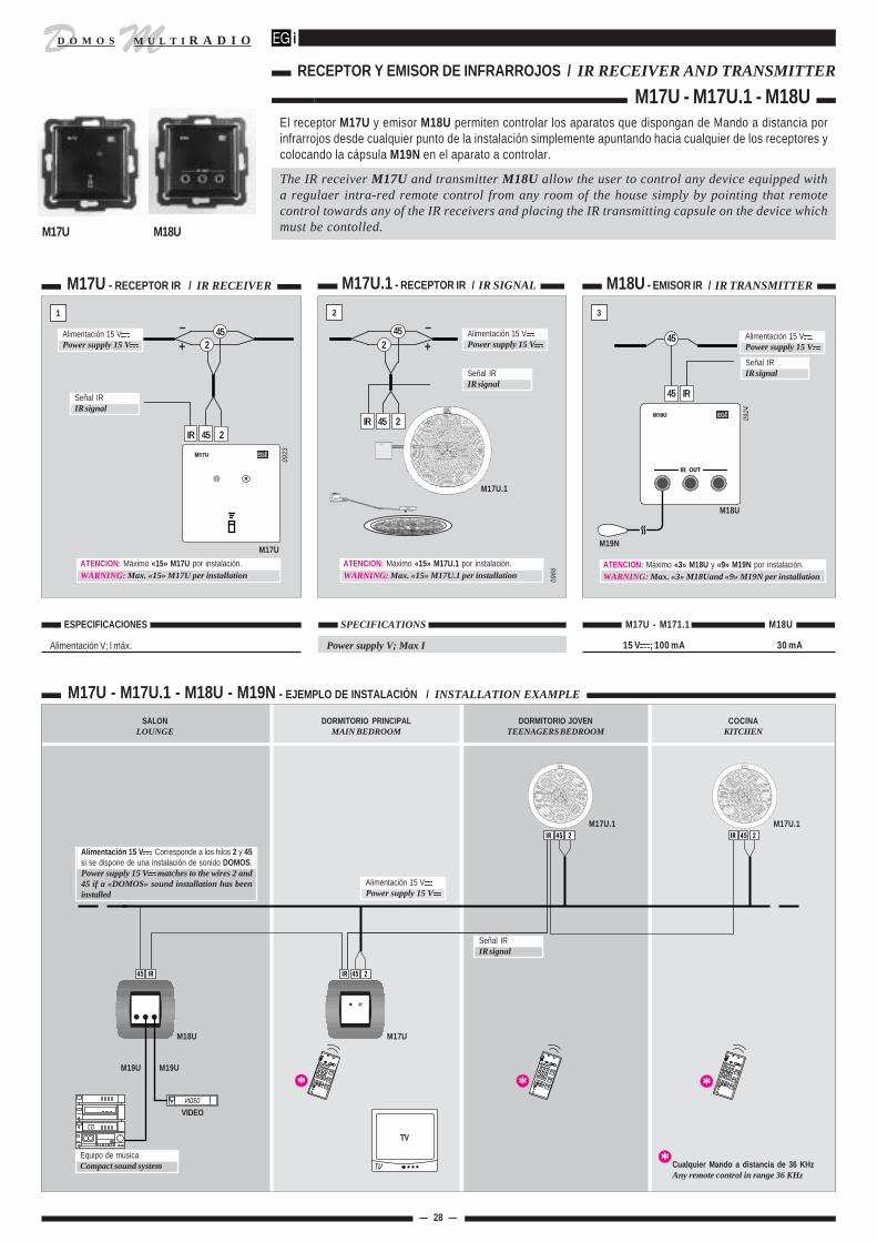
D MM U L T I R A D I OD O M O S
*
*
**
M17U
El receptor M17U y emisor M18U permiten controlar los aparatos que dispongan de Mando a distancia porinfrarrojos desde cualquier punto de la instalación simplemente apuntando hacia cualquier de los receptores ycolocando la cápsula M19N en el aparato a controlar.
The IR receiver M17U and transmitter M18U allow the user to control any device equipped witha regulaer intra-red remote control from any room of the house simply by pointing that remotecontrol towards any of the IR receivers and placing the IR transmitting capsule on the device whichmust be contolled.
— 28 —
RECEPTOR Y EMISOR DE INFRARROJOS / IR RECEIVER AND TRANSMITTER
M17U - M17U.1 - M18U
ual
45 IR
45
M19N
Señal IRIR signal
M18U
ATENCION: Máximo «3» M18U y «9» M19N por instalación.WARNING: Max. «3» M18Uand «9» M19N per installation
0924
M17U - RECEPTOR IR / IR RECEIVER
1
M17U.1 - RECEPTOR IR / IR SIGNAL
2
IR 45 2
45Alimentación 15 VPower supply 15 V
Señal IRIR signal
2
M17U
0923
ATENCION: Máximo «15» M17U por instalación.WARNING: Max. «15» M17U per installation
M18U - EMISOR IR / IR TRANSMITTER
3
M17U.1
0966
Señal IRIR signal
IR 45 2
452
M17U - M17U.1 - M18U - M19N - EJEMPLO DE INSTALACIÓN / INSTALLATION EXAMPLE
Alimentación V; I máx.
ESPECIFICACIONES SPECIFICATIONS
Power supply V; Max I
M17U - M171.1 M18U
15 V ; 100 mA 30 mA
Señal IRIR signal
M17U.1 M17U.1
M17UM18U
M19UM19U
Equipo de músicaCompact sound system
VIDEO
TV
Cualquier Mando a distancia de 36 KHzAny remote control in range 36 KHz
SALONLOUNGE
DORMITORIO PRINCIPALMAIN BEDROOM
DORMITORIO JOVENTEENAGERS BEDROOM
COCINAKITCHEN
–+
Alimentación 15 VPower supply 15 V
–+
ATENCION: Máximo «15» M17U.1 por instalación.WARNING: Max. «15» M17U.1 per installation
Alimentación 15 VPower supply 15 V
Alimentación 15 VPower supply 15 V
Alimentación 15 V Corresponde a los hilos 2 y 45si se dispone de una instalación de sonido DOMOS.Power supply 15 V matches to the wires 2 and45 if a «DOMOS» sound installation has beeninstalled
M18U
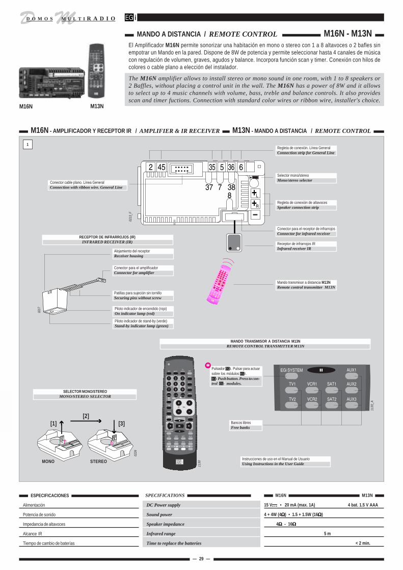
D MM U L T I R A D I OD O M O S
1130
_A
2 45 35 5
L
R
636
837 7 38
12
345
68
9
7
0/101-/11
2-/12
SETMUTE TVVIDEO
MAC1
MAC2
MAC3
MAC4
KIDS
TXT / TVEGi SYSTEM
AUX1
AUX2
AUX3
TV1
TV2
VCR1
VCR2
SAT1
SAT2
OFF
El Amplificador M16N permite sonorizar una habitación en mono o stereo con 1 a 8 altavoces o 2 bafles sinempotrar un Mando en la pared. Dispone de 8W de potencia y permite seleccionar hasta 4 canales de músicacon regulación de volumen, graves, agudos y balance. Incorpora función scan y timer. Conexión con hilos decolores o cable plano a elección del instalador.
The M16N amplifier allows to install stereo or mono sound in one room, with 1 to 8 speakers or2 Baffles, without placing a control unit in the wall. The M16N has a power of 8W and it allowsto select up to 4 music channels with volume, bass, treble and balance controls. It also providesscan and timer fuctions. Connection with standard color wires or ribbon wire, installer's choice.
— 29 —
ESPECIFICACIONES
Alimentación
Potencia de sonido
Impedancia de altavoces
Alcance IR
Tiempo de cambio de baterías
15 V • 20 mA (max. 1A) 4 bat. 1.5 V AAA
4 + 4W (4ΩΩΩΩΩ) • 1.5 + 1.5W (16ΩΩΩΩΩ)
4ΩΩΩΩΩ - 16ΩΩΩΩΩ
5 m
< 2 min.
M16N M13N SPECIFICATIONS
DC Power supply
Sound power
Speaker impedance
Infrared range
Time to replace the batteries
MANDO A DISTANCIA / REMOTE CONTROL M16N - M13N
M16N
M16N - AMPLIFICADOR Y RECEPTOR IR / AMPLIFIER & IR RECEIVER M13N - MANDO A DISTANCIA / REMOTE CONTROL
1
Selector mono/stereoMono/stereo selector
Regleta de conexión de altavocesSpeaker connection strip
Regleta de conexión. Línea GeneralConnection strip for General Line
Conector para el receptor de infrarrojosConnector for infrared receiver
Receptor de infrarrojos IRInfrared receiver IR
Mando transmisor a distancia M13NRemote control transmitter M13N
Conector para el amplificadorConnector for amplifier
Alojamiento del receptorReceiver housing
Patillas para sujeción sin tornilloSecuring pins without screw
RECEPTOR DE INFRARROJOS (IR)INFRARED RECEIVER (IR)
Piloto indicador de encendido (rojo)On indicator lamp (red)
Piloto indicador de stand-by (verde)Stand-by indicator lamp (green)
0217
0213
_F
Conector cable plano. Línea GeneralConnection with ribbon wire. General Line
SELECTOR MONO/STEREOMONO/STEREO SELECTOR
[2][1]
MONO STEREO
[3]
0226
1130
MANDO TRANSMISOR A DISTANCIA M13NREMOTE CONTROL TRANSMITTER M13N
Instrucciones de uso en el Manual de UsuarioUsing Instructions in the User Guide
ual
1 2 3
4 5 6
8 97
0/10 1-/11 2-/12
SET MUTETV
VIDEO
MAC1
MAC2
MAC3
MAC4
KIDS
TXT / TV
EGi SYSTEM AUX1
AUX2
AUX3
TV1
TV2
VCR1
VCR2
SAT1
SAT2
OFFPulsador . Pulsar para actuarsobre los módulos .
Push button. Press to con-trol modules.
Bancos libresFree banks
*
M13N

D MM U L T I R A D I OD O M O S
— 30 —
ESQUEMAS / WIRING DIAGRAMS M16N - M13N
M16N4 CANALES DE MUSICA. CONEXION CON HILOS4 MUSIC CHANNELS. STANDARD WIRES CONNECTIONM16N
1 CANAL DE MUSICA1 MUSIC CHANNEL
2 3
M16NM16N4 CANALES. CONEXION CON CABLE PLANO4 MUSIC CHANNELS. RIBBON WIRE CONNECTION
54
CONEXION DE ALTAVOCESSPEAKERS CONNECTION
Bafles de 4 - 8 Ω4 - 8ΩΩΩΩΩ baffles
+ +
POTENCIA POR ALTAVOZPOWER PER SPEAKER
nº altav.speakers
1 ÷ 2 4 W 1.5 W4 1.3 W6 1.2 W8 1 W
4 ΩΩΩΩΩ 16 ΩΩΩΩΩ
2 x 0.75 mm2+L
R+
M16N
+ +
0600
_A
+ +
+ +
+ +
De 2 hasta 8 altavoces de 16 ΩFrom 2 to 8, 16Ω speakers
Si instala sólo1 altavoz (mono) colo-que el selector en posición mono.If you install a single speaker(mono) place the selector in themono position.
12
345
68
9
7
0/101-/11
2-/12
SETMUTE TVVIDEO
MAC1
MAC2
MAC3
MAC4
KIDS
TXT / TV
EGi SYSTEM
AUX1
AUX2
AUX3
TV1
TV2
VCR1
VCR2
SAT1
SAT2
OFF
2 x 0.75 mm2
+
M16N
+M13N
2 x
0.75
mm
2
STEREO
0600
_B
2 45
Receptor IRIR Receiver
R16N
R14N
R16N
+L
R+
12
345
68
9
7
0/101-/11
2-/12
SETMUTE TVVIDEO
MAC1
MAC2
MAC3
MAC4
KIDS
TXT / TV
EGi SYSTEM
AUX1
AUX2
AUX3
TV1
TV2
VCR1
VCR2
SAT1
SAT2
OFF
+L
R+
+
M16N
+
R18N
M13N
2 x
0.75
mm
2
STEREO
0599
_B
2 45
45
2
5
35
35 5
Receptor IRIR Receiver
12
345
68
9
7
0/101-/11
2-/12
SETMUTE TVVIDEO
MAC1
MAC2
MAC3
MAC4
KIDS
TXT / TV
EGi SYSTEM
AUX1
AUX2
AUX3
TV1
TV2
VCR1
VCR2
SAT1
SAT2
OFF
Receptor IRIR Receiver
M16N
2 x
0.75
mm
2
STEREO
M13N
6
R13N
2 45 35 5 36 6
8
37 7 38
245
355
377
36
388
+L
R+
+
+
0599
_C
ual

D MM U L T I R A D I OD O M O S
D47U
— 31 —
Mando de 1 canal de sonido stereo con radio FM incorporada para sonorizar en mono (1 altavoz) o en stereo(2 altavoces) una habitación. Regulador de volumen digital. Tienen la potencia adecuada para una habitaciónpero si se desea aumentarla añádase un Amplificador E17G. Protección contra equivocaciones de conexionadoy cortocircuitos en el altavoz.
El funcionamiento del producto se describe en el "Manual del usuario".
Stereo Control unit able to play 1 audio program. It provides mono (1 speaker) or stereo (2speakers) sound for a room. Digital volume regulation. Its power is suitable for one room, but ifyou want to increase it, you can add an E17G amplifier. Protected against mistaken connectionsand loudspeaker short-circuits.
Our user's manual shows how to operate this product.
D47U - 1 CANAL DE SONIDO STEREO + RADIO FM / 1 STEREO AUDIO PROGRAM + FM TUNER
1
Alimentación V; I máx.
Potencia audio
Impedancia de los altavoces
Conector para auriculares
Timer (apagado en)
Sintonía en FM
Sensibilidad
ESPECIFICACIONES
2
D47U D47UHABITACION CON SONIDO STEREOROOM WITH STEREO SOUND
HABITACION CON SONIDO MONOROOM WITH MONO SOUND
2 45 5 35
2 altavoces de 16Ω o 4 de 32ΩTwo 16ΩΩΩΩΩ or four 32Ω Ω Ω Ω Ω speakers
D47U
0866
2 x 0.75 mm2
+
+
+ +
5
2
35
455
245
35
2 x 0.75 mm2
2 45 5 35 + +
D47U
+
Regulador de volumenVolume control
0864
Línea GeneralGeneral Line
SPECIFICATIONS
Power supply V; Max I
Audio power
Speaker impedance
Headphones socket
Timer (sleep time)
Tuning frequency range
Sensitivity
D47U
15 V ; 330 mA
1.25 W x 2
1÷2 x 16 Ω Ω Ω Ω Ω • 4 x 32 ΩΩΩΩΩ
sólo stereo/stereo only: 8 ÷ 600 ΩΩΩΩΩ
45 min.
88÷108 MHz
> -20 dBm
Selector mono/stereoMono/stereo selector
MONO
STEREO
1 ó 2 altavoces1 or 2 speakers2 ó 4 altavoces2 or 4 speakers
MONO STEREO
HILOS DE LA LINEA GENERALGENERAL LINE WIRES
Ref. cableCable ref.
R18N 4 1
Nº de hilosNr. of wires
0865
Selector mono/stereoMono/stereo selector
Conexión a Línea GeneralGeneral Line connection
Conexión a Línea GeneralGeneral Line connection
Salida para auriculares stereoStereo headphones socket
Pulsador de encendido/apagado y timerON/OFF and Timer push-button
ual
Conexión de altavoces y antenaSpeaker / antenna connection
/– /–
FM - LocalFM - Local
Regulador de volumenVolume control
Pulsador ResetReset Push-button
Selector radio / músicaSelector"central" "local"
Piloto de radioPilot lamp "local" -FMtuner-
Piloto de músicaPilot lamp "central"
Pulsador de sintonía (Tuning)Tuning push-button
*
*
ATENCION: El hilo (–) del altavoz, borna , es también la antena de la radio. Cuando se coloque un altavoz de 2" junto al Mando la longitud del cable será demasiado corta y habrá que añadir un cable de longitud mayorque 1 m. Este cable se puede colocar dentro del tubo de la Línea General.WARNING: The wire (–) fixed at the loudspeaker terminal block acts also as an antenna for the radio. When a 2” speaker is installed next to the control unit the length of this antenna will be too short,and then an extra wire of min. 1 m long must be connected to the mentioned terminal block. This wire can be placed inside the conduit for the general line.
Altavoz 16 Ω16 ΩΩΩΩΩ speaker
+ +/–
Cable deantena auxiliarWire for auxiliaryantenna
*
MANDO CON SINTONIZADOR FM / CONTROL UNIT WITH BUILT-IN FM TUNER D47U

D MM U L T I R A D I OD O M O S
20W 10 + 10W10 + 10W
20W L20W R
452 STAND-BYON35L5R LN
RL
GE E17G E18GAmplificador / Amplifier
— 32 —
AMPLIFICADOR 20W / 20W AMPLIFIER E17G - E18GPara aumentar la potencia del sonido de una habitación hasta 20 ó 40W cuando se desee conectar Bafles,Altavoces HI-FI o muchos Altavoces. Sonido HI-FI, mono o stereo dependiendo del Mando.
Incorpora protección automática contra cortocircuitos en las salidas de alimentación y altavoces, medianteinterruptor térmico de rearme automático. Se desconecta automáticamente de la red al apagar la Central.
To increase the sound power in one room to 20 or 40 W for connnecting HI-FI loudspeakers or severalloudspeakers. HI-FI sound, mono or stereo according to the Control unit.
This amplifier has a built-in automatic protection against short circuits at the power supply outputs andloudspeakers, by means of a self-restoring thermal switch. It is automatically disconnected from the mainswhen the Central is switched OFF.
E17G - CONEXION CON HILOS / STANDARD WIRES CONNECTION E18G - CONEXION CON CABLE PLANO / RIBBON WIRE CONNECTION
Radiador de calorHeat radiator
Conexión altavocesSpeakers connection
Conexión a red 230 V~Connection to 230 V~ supply
Conexión a Línea GeneralConnection to General Line
Entrada de audioAudio input
Conexión con cable planoConnection with ribbon wire
Fijación a rail DIN de 35 mm.Fastening to 35 mm DIN rail.
0343
_E03
43_D
1
ESPECIFICACIONES
Alimentación red
Consumo
Potencia de sonido
Impedancia de altavoces
Salida de tensión continua
Nº de amplificadores por Mando
SPECIFICATIONS
Mains power supply
Consumption
Sound power
Speaker impedance
DC output
Nr. of amplifiers per Control unit
E17G E18G
Montaje del amplificadorAmplifier assembly
2
0383
_A230 V~ ± 10% • 50/60 Hz
2.5 VA (max. 36 VA)
10 + 10W (2ΩΩΩΩΩ) • 20W (4ΩΩΩΩΩ)
2 - 16ΩΩΩΩΩ (10 + 10W) • 4 - 16ΩΩΩΩΩ (20W)
15 V (max. 1.5 A)
4 u.
Configuración Amplificador MandoSetup Amplifier Control unit
10 + 10WMONO
10 + 10WSTEREO
20WMONO
MONO
STEREO
MONO
Amplif.1
Amplif.2
20 + 20WSTEREO STEREO
L
R
0140
_BSólo E18GOnly E18G
ATENCION: El número máximo total de amplificadores E17G(E18G) + alimentadores K12G en una instalación es de 4 unidades.Si precisa instalar más de 4 unidades E17G (E18G) es precisocolocar un fusible de 100 mA en la borna "2" de las unidadesadicionales.
WARNING: The maximum total number of E17G (E18G)amplifiers and K12G power supplies in a system is 4 units.If you need to install more than 4 E17G (E18G) units you must placea 100 mA fuse in the terminal block "2" of the additional units.
45
355
2
2 45 5 35
100 mA
Línea GeneralGeneral Line
0706
E17G
ual

D MM U L T I R A D I OD O M O S
RL
GE E17G E18GAmplificador / Amplifier
— 33 —
ESQUEMAS / WIRING DIAGRAMS E17G - E18G
R++L+ ++
R18N
2
455
35
2 45 5 35
R18N
10 W + 10 W
230 V~
E17G E17G4 CANALES DE MUSICA. CONEXION CON HILOS. 10+10W4 MUSIC CHANNELS. STANDARD WIRES CONNECTION. 10 + 10W
1 CANAL DE MUSICA. 10+10W1 MUSIC CHANNEL. 10+10W
3 4
+L +2 45 5 35
D24D - M16N - D26D - D42U - D44U - D46U
R
0584
_A
+L R+
+5 35
20 W
E17G
D25D (Mono)D41U - D45U
STEREO
Conexión altavocesVer esquema 5Loudspeaker connectionSee diagram 5
10 +10 W
R13N
E17G
7
838
36
6
37
230 V~
355
245
2 45 5 35
R++L++ +20 W 10W + 10WR13N
0584
_B
38 8 37 7 36 6 35 5 45 2 +R L+Conexión altavocesVer esquema 5Loudspeaker connectionSee diagram 5
canal / channel 4
canal / channel 3
canal / channel 2
canal / channel 1
STEREO
10 +10 W
E17G / E18GCONEXION DE ALTAVOCESLOUDSPEAKER CONNECTION
5
Nº de altavocesSpeakers
POTENCIA POR ALTAVOZPOWER PER SPEAKER
4 ΩΩΩΩΩ 8ΩΩΩΩΩ 16ΩΩΩΩΩ 32ΩΩΩΩΩ
1 20W 13W 8W 4W
2 10W 6W 3W
3 5.5W 2.75W
4 5W 2.5W
5 / 6 2W
0584
_C
+ + + + +
+ + + + +
Nº de altavocesSpeakers
POTENCIA POR ALTAVOZPOWER PER SPEAKER
4 ΩΩΩΩΩ 8ΩΩΩΩΩ 16ΩΩΩΩΩ 32ΩΩΩΩΩ
2 7W 4W 2W
4 5W 3.5W 2W
6 / 8 2.5W 1.7W
10 / 16 1.2W 0.5W
18 /24 0.5W
Repartir los altavoces entre lasdos salidas.Distribute the loudspeakersevenly between both outputs.
+++++
20WMONO MONO
Amplif.120 + 20WSTEREO STEREO
L
0140
_F
Configuración Amplificador MandoSetup Amplifier Control unit
Amplif.2
Configuración Amplificador MandoSetup Amplifier Control unit
10 + 10WMONO
10 + 10WSTEREO
MONO
STEREO01
40_G
R
E17G / E18G
20 W 10 +10 W
D13D - M16N (hasta 4 canales / up to 4 channels)D44U - D46U - D26D (2 canales / 2 channels)
l
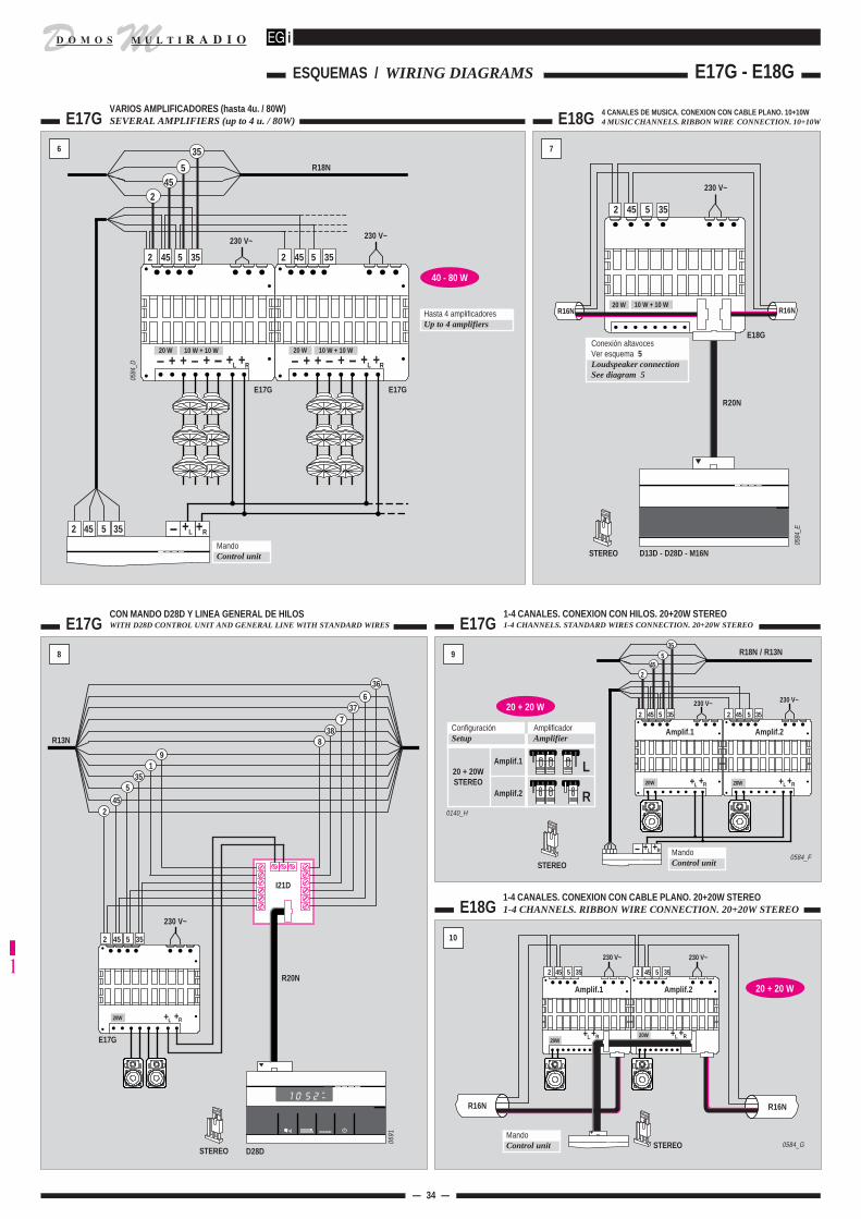
D MM U L T I R A D I OD O M O S
— 34 —
E17GCON MANDO D28D Y LINEA GENERAL DE HILOSWITH D28D CONTROL UNIT AND GENERAL LINE WITH STANDARD WIRES E17G
8
10
E18G
1-4 CANALES. CONEXION CON HILOS. 20+20W STEREO1-4 CHANNELS. STANDARD WIRES CONNECTION. 20+20W STEREO
2
2 45 5 35 2 45 5 35
230 V~
20W +L +R ++L R20W
Amplif.1
0584_F
Amplif.2
9
Amplif.1
Amplif.2
20 + 20WSTEREO
L
R
Configuración AmplificadorSetup Amplifier
+R+L MandoControl unitSTEREO
35
455
230 V~
2 45 5 35
230 V~
Amplif.1 Amplif.2
2 45 5 35
20W20W
++L R++L R
MandoControl unit STEREO
R16NR16N
0584_G
R18N / R13N
0140_H
20 + 20 W
R20N
+L +R20W
I21D
E17G
245
535
19
R13N
37
388
636
7
2 45 5 35
230 V~
D28DSTEREO
0691
E17GVARIOS AMPLIFICADORES (hasta 4u. / 80W)SEVERAL AMPLIFIERS (up to 4 u. / 80W)
6
245
5
35
2 45 5 35
230 V~
E17G
0584
_D
E17G
R++L+ ++20 W 10 W + 10 W
R++L+ ++20 W 10 W + 10 W
2 45 5 35
R18N
MandoControl unit
+L2 45 5 35 +R
Hasta 4 amplificadoresUp to 4 amplifiers
40 - 80 W
E18G
7
Conexión altavocesVer esquema 5Loudspeaker connectionSee diagram 5
2 45 5 35
R16NR16N
E18G
0584
_E
D13D - D28D - M16NSTEREO
R20N
20 W 10 W + 10 W
230 V~
4 CANALES DE MUSICA. CONEXION CON CABLE PLANO. 10+10W4 MUSIC CHANNELS. RIBBON WIRE CONNECTION. 10+10W
20 + 20 W
230 V~
1-4 CANALES. CONEXION CON CABLE PLANO. 20+20W STEREO1-4 CHANNELS. RIBBON WIRE CONNECTION. 20+20W STEREO
230 V~
ESQUEMAS / WIRING DIAGRAMS E17G - E18G
l

D MM U L T I R A D I OD O M O S
452 STAND-BY35L5R LN
15 V 1.5 A max. GE K12GPower SupplyAlimentador
Made in E.U. ± 10% 50/60 Hz
452 STAND-BY35L5R LN
15 V 1.5 A max. GE K12GPower SupplyAlimentador
Made in E.U. ± 10% 50/60 Hz
— 35 —
ALIMENTADOR / POWER SUPPLY K12G - K12G/IN El alimentador auxiliar K12G se utiliza para ayudar a la Central en la alimentación de instalaciones con elevadoconsumo en 15 V ; como las que cuentan con muchos Mandos con intercomunicador. Si en la instalación hay2 Centrales o amplificadores E17G o E18G, probablemente, no sea necesario colocar alimentadores (ver tabla).
El alimentador K12G/IN se utiliza en instalaciones con intercomunicadores J12U sin música, es decir cuandono hay Central (ver pág. 20, fig. 3).
The auxiliary power supply K12G is used to assist the Central unit when it powers installationswith high consumption in 15 V , like those that have many many Control units with intercom. Ifthere are 2 Central units or E17G or E18G amplifiers in the installation, it probably will not benecessary to install power supplies (see table).
The power supply K12G/IN is used in no-music installations with Intercom units J12U. In this case,no Central unit is required (see page 20, fig. 3).
K12G - ALIMENTADOR / POWER SUPPLY
1
ESPECIFICACIONES
Alimentación red
Consumo (stand-by / máx.)
Salida de tensión continua
Nº de alimentadores por instalación
SPECIFICATIONS
Mains power supply
Consumption (stand-by / max)
D C output
Nr. of power supplies per installation
K12G K12G/IN 3
230 V~ ± 10% • 50/60 Hz
2.5 VA (max. 36 VA)
15 V (max. 1.5 A)
3 u.
Montaje del amplificadorAmplifier assembly
0383
_A
CONEXION A LINEA GENERAL DE HILOS NORMALESCONNECTION TO A GENERAL LINE WITH STANDARD WIRES
2.12
45
2
355
230 V~
K12G
0696
R13N - R15NR18N - R19N
Radiador de calorHeat radiator
Conexión a red 230 V~Connection to mains 230 V~
Conexión a Línea GeneralConnection to General Line
0694
¿CUANDO HAY QUE INSTALAR ALIMENTADORES K12G?WHEN SHOULD YOU INSTALL K12G POWER SUPPLIES?
1 alimentador K12G cada 5 Mandos D28D(Nota: La Central puede alimentar sólo 4 u. D28D)1 K12G power supply for every five D28D Control units.(Note: The Central unit can power only 4 D28D)
1 alimentador K12G cuando se utilicen más de 7 u. D46U / D26D con el máximovolumen en intercomunicación.1 K12G power supply if more than seven D46U / D26D ,with maximumvolume for intercom, are used.
Cuando se instala más de 8 u. M16N con altavoces de 16Ω o más de 4 u.M16N con altavoces de 4Ω.When you install more than eight M16N units with 16Ω loudspeakersor more than four M16N units with 4Ω loudspeakers.
Cuando se observe un calentamiento excesivo de la Central. Si se hace unuso intensivo de la instalación con muchos Mandos permanentemente encen-didos o con volumen elevado.If you notice an overheating in the Central unit. If the installation isunder intensive use with many Control units permanently turned on orwith loud volumes.
Con MandosD28D
With D28DControl units
Con MandosD46U / D26D
With D46U / D26DControl units
Con AmplificadorM16N
With M16NAmplifiers
En general
Generally
K12G
K12G
ual
K12G

D MM U L T I R A D I OD O M O S
l
1091
ALTAVOCES DE 8" EN CAJA BAFLE H26N8" LOUDSPEAKER IN BOX H26N
MONTAJE DE ALTAVOCES DE 8" EN CAJA DE EMPOTRAR V17B8" LOUDSPEAKER ASSEMBLY IN V17B BOX
Rejilla H25BH25B Grille
MONTAJE DE ALTAVOCES DE 8" / 8" LOUDSPEAKER ASSEMBLY
— 36 —
Rejilla H12BH12B Grille
TornilloScrew
TapitaRound cover
ArandelaWasher
0151
_A
0389
La tapita cierra el orificio para el destornillador.The round cover closes the hole for the screw-driver
0388
_A
TapitaRound cover
Rejilla H24BH24B Grille
0386
Montar el tornillo y la pieza de plástico en el alojamiento de la
cara interior de la rejilla.Place the screw and the round cover in the housing onthe inner side of the grille.
0396
0120
Caja V17BV17B Box
Falso techoFalse ceiling
0397_A
Caja V17BV17B Fitting box
Altavoz de 8"8" loudspeaker Tornillo
Screw
TapitaRound cover
Presionar hasta oir "CLICK" en los tres puntos de anclajePress until hearing a "click" at the fixing points
0158
CAJA DE EMPOTRAR DE 8" CON KIT H11N EN TECHOS FALSOS8" FITTING BOX WITH H11N KIT IN FALSE CEILINGS
COLOCACION DE LA REJILLA H12BASSEMBLY OF H12B GRILLE
1 2
3 4
5 6
COLOCACION DE LA REJILLA H24BASSEMBLY OF H24B GRILLE
FrontalFront cover
Altavoz de 8"8" loudspeaker
Caja bafle H26NH26N Box
Kit de fijación H11NH11N fixing kit
COLOCACION DE LA REJILLA H25B Y 0603ASSEMBLY OF H25B AND 0603 GRILLE
Rejilla 06030603 Grille
TornilloScrew

D MM U L T I R A D I OD O M O S
l
MONTAJE DE ALTAVOCES DE 5" EN CAJA DE EMPOTRAR V19AASSEMBLY OF 5" LOUDSPEAKERS IN BOX V19A
— 37 —
COLOCACION DE LA REJILLA H16A, H13A Y 0602ASSEMBLY OF H16A, H13A AND 0602 GRILLE
ALTAVOZ DE 5" EN CAJA BAFLE H27N5" LOUDSPEAKER IN H27N BOX
0120
Caja bafle H27NH27N box
Altavoz de 5"5" loudspeaker
Rejilla H16AH16A Grille
TornilloScrew
ArandelaWasher
1093
0103
Fijar los muelles en el soporte metálico con el ángulo hacia abajo " " para techos o tabiques delgados
de 5 a 35 mm. de espesor.Fix the springs to the metallic support.Place them downwards " " for thin ceilings orwalls from 5 to 35 mm.
0104
Fijar los muelles en el soporte metálico con el ángulo hacia arriba " v " para techos o tabiques gruesos
de 35 a 55 mm. de espesor.Fix the springs upwards " v " for thick walls or ceilings from 35 to 55 mm.
APROVECHANDO EL FALSO TECHOFALSE CEILING MOUNTING
0101
Techo o tabiqueCeiling or wall
Aro H28NH28N Ring
0209
Aro de plástico de 5"5" Plastic ring
Soporte metálicoMetallic support
MuelleSpring
>
>
MuelleSpring
>
PRESIONARPRESS
MONTAJE DE ALTAVOCES DE 5" / 5" LOUDSPEAKER ASSEMBLY
COLOCACION DE LA REJILLA H17AASSEMBLY OF H17A GRILLE
Caja V19AV19A Fitting box
Altavoz de 5"5" loudspeaker
0158
Presionar hasta oir "CLICK" en los tres puntos de anclaje.Press until hearing a"click" at the 3 fixing points.
Rejilla H17AH17A Grille
TornilloScrew
TapitaCover
0153
_B
FrontalFront cover
>
>
MONTAJE DE LOS MUELLES SEGUN EL GROSOR DEL TECHOPRINGS MOUNTING ADAPTED TO CEILING THICKNESS
1 2
4
3
5
6ARO CON MUELLES H28N
RING WITH SPRINGS H28N
7
0154_A
Sujetamos la rejilla con un tornillo central, tapándolo después con el embellecedor
hasta oir "CLICK".The grille is fixed by a central screw which is hidden with the cover. To insertthe cover, press until hearing "click".
PARA EMPOTRAR SIN OBRA EN TECHOS O TABIQUESWALL OR CEILING MOUNTING WITHOUT MAISONWORK
>
TornilloScrew
TapitaRound cover
Rejilla H13AH13A Grille
Rejilla 06020602 Grille

D MM U L T I R A D I OD O M O S
l
Cable receptor de in-frarrojosIR receiver cable
— 38 —
MONTAJE DE ALTAVOCES DE 5" CON MANDO A DISTANCIA ASSEMBLY OF 5" LOUDSPEAKERS WITH REMOTE CONTROL
H28N
AltavozLoudspeaker
Pasacables del H28NH28N cable groose
RejillaGrille
Receptor de infrarrojosIR receiver
Cable del receptor IRCable of the IR receiver
Antes de colocar el Altavoz, pase el cable del Receptor de Infrarrojos por el Pasacable del Aro, sólo así
podrá oir el "CLICK" de sujeción del Altavoz.Before placing the loudspeaker, insert the IR receiver cable through the cable groove in theH28N ring. Otherwise, you will not hear the "click" when trying to fix the speaker.
0159
0172
0155
Receptor de infrarrojosIR receiver
Diámetro agujeroHole diameter
16 cm. Profundidad mínimaMinimum depth11 cm.
Amplificador del Mandoa DistanciaRemote Control am-plifier
Techo o tabiqueCeiling or wall
Aro H28NH28N Ring
Altavoz de 5"5" loudspeaker
Cable altavozLoudspeaker cable Techo de pasillo
Corridor ceiling
TabiqueWall
Cable línea generalGeneral line
Amplificador con Man-do a DistanciaRemote Control am-plifier
La conexión y colocación del Amplificador, en el techo o tabique, debe realizarse antes de fijar el conjunto.
El Receptor de infrarrojos y el Cable Altavoz debe quedar en el exterior.The amplifier must be connected and placed before fixing the rest of the elements.The IR receiver and the loudspeaker cable must stay outside.
EJEMPLO DE INSTALACIONEN UN TECHO BAJO DE PASILLO
EXAMPLE OF INSTALLATION IN ACORRIDOR FALSE CEILING
APROPIADO PARA VIVIENDAS SIN PREINSTALACION CON FALSO TECHO EN PASILLOUSEFULL IN HOMES WITHOUT PRE-INSTALLATION, WITH FALSE CEILING IN CORRIDOR
COLOCACION DEL RECEPTOR DE INFRARROJOSPLACING OF THE IR RECEIVER
1
2 3
0160
Receptor de infrarrojosIR Receiver
RejillaGrille
TornilloScrew
TapitaCover
Sujetamos la rejilla con un tornillo central, tapándolo después con el embellecedor hasta oir "CLICK".The grille is hold by a central screw, which is hidden later by the cover. Press until you hear a"click".
RESULTADO FINAL EN TECHOEND RESULT IN CEILING
0161
RESULTADO FINAL EN TABIQUEEND RESULT IN WALL
0154
MONTAJE DE LA REJILLAGRILLE MOUNTING

D MM U L T I R A D I OD O M O S
l
MONTAJE DE ALTAVOZ 5’’ EN PREINSTALACIONES EGi DE 5’’ O DE OTRAS MARCAS5” LOUDSPEAKER ASSEMBLY IN 5” PRE-INSTALLATIONS
SUJECION DEL CONJUNTO EN LA CAJA DE EMPOTRAR Y MONTAJE DE LA REJILLAMOUNTING OF THE SPEAKER SET IN TO THE FITTING BOX
MONTAJE DEL ALTAVOZ DE 5" EN EL ADAPTADOR H23BMOUNTING OF 5" LOUDSPEAKER IN ADAPTER H23B
— 39 —
Altavoz de 5"Loudspeaker
Adaptador H23BH23B Adapter
0083_A
Hacer coincidir la muesca del Altavoz y el Adaptador. Presionar hasta oir "CLICK".The groove in the loudspeaker must join the one in the adapter. Press until hearing a "click".
Pieza para dejar colgados los altavoces mientras
se termina y comprueba la instalación.Element to hang the loudspeakers while the systemis tested.
Caja de 8"8" Fitting box
Conjunto altavoz + adaptadorLoudspeaker + Adapter
Apriete los tornillos de las 4 uñasFasten the screws of the 4 claws
0225
_A
0117
_A
Rejilla H12B, H24B y H25BH12B, H24B or H25B Grille
ArandelaWasher
TornilloScrew
0152
MONTAJE DE ALTAVOCES DE 5" / 5" LOUDSPEAKER ASSEMBLY MONTAJE DE ALTAVOCES DE 5" EN PREINSTALACIONES DE 8" Y 5" ANTIGUAS O DE OTRAS MARCAS / 5" LOUDSPEAKER ASSEMBLY IN 8" AND 5" PRE-INSTALLATION BOXES
MONTAJE DEL ALTAVOZ DE 5" EN EL ADAPTADOR H23B / 5" LOUDSPEAKER ASSEMBLY IN H23B ADAPTOR
0080
Uña metálicaMetallic claw
Adaptador H23BH23B Adapter
Goma elásticaElastic rubber
0081
Caja de 8"8" Fitting box
Goma elásticaElastic rubber
Uña metálicaMetallic claw
TuercaNut
AdaptadorAdapter
TornilloScrew
DETALLE DEL MONTAJE DE LAS UÑAS METALICASMOUNTING DETAIL OF THE METALLIC CLAWS
1
2 3
ATENCION: Al colocar rejillas de 8" con el adaptador H23B tire el tornillo que viene con larejilla y utilice el tornillo de 14 mm. sin punta de la bolsa del adaptador.ATTENTION: When mounting 8" grilles with H23B adapter, ignore the screw thatcomes together with the grille and use the 14mm. flat-end one in the adapter bag.
4
Caja empotrada de otras marcas* Para adaptar romper la trasera de la cajaFitting box
Altavoz 5’’ EGi5’’ EGi Loudspeaker
Aro 07030703 Ring
COMIENZO / BEGINNING FINAL / END
1095

D MM U L T I R A D I OD O M O S
l
MONTAJE DE ALTAVOCES DE 5" RECTANGULAR 5" RECTANGULAR LOUDSPEAKER ASSEMBLY
— 40 —
0399
0400
0401
0402
Junta de gomaRubber Gasket
ArandelaWasher
TornilloScrew
INSERTARINSERT
ALOJAMIENTO PARA AMPLIFICADOR DEL MANDO A DISTANCIAHOUSING FOR REMOTE CONTROL AMPLIFIER
0126_A
Altavoz de 5"5" Loudspeaker
Amplificador del Mando a distanciaRemote Control amplifier
0129
Caja de empotrar V11FV11F Fitting box
Altavoz de 5"5" Loudspeaker
ParedWall
TornilloScrew
Rejilla H19FH19F Grille
0398_A
Caja-bafle H22F/NEH22F/NE Box
ParedWall
Altavoz de 5"5" Loudspeaker
Rejilla H19FH19F Grille
TornilloScrew
1 2
3 ROMPERBREAK
5
01340404
RESULTADO FINAL EN RINCONEND RESULT IN A CORNER
MONTAJE DE ALTAVOZ EMPOTRADO EN LA PAREDFITTING OF BUILT-IN SPEAKER IN WALL
MONTAJE DE ALTAVOZ SALIENTE DE LA PAREDMOUNTING OF PROTRUDED LOUDSPEAKER
APROVECHANDO EL FALSO TECHO DEL PASILLOINSTALLATION IN CORRIDOR FALSE CEILING
4
MONTAJE DE ALTAVOZ SALIENTE EN UN RINCON DE LA PAREDMOUNTING OF PROTRUDED LOUDSPEAKER IN A WALL CORNER

D MM U L T I R A D I OD O M O S
l
— 41 —
Romper todas las ventanas necesarias para pasar los cables y acoplar las cajas.Break all the windows you need to introduce cables and set the boxes together.
0220
0221
0212
V13D
ROMPERBREAK
Caja V15CV15C fitting box
Cable línea general (4 hilos)General line (4 wires)
Caja V13DV13D Fitting box
Marquillo W13DW13D Frame
MandoControl unit
EmbellecedorTrim
Cable altavoz (2 hilos)Loudspeaker cable (2 wires)
Altavoz de 3"3" Loudspeaker
RejillaGrille
0224
0182
TapajuntasFrame
0178
W21N/BL W22N/BL
MANDO / CONTROL UNIT
EN PAREDES CON AZULEJOSON TILE WALLS
0184
EN PAREDES EN GENERALON NORMAL WALLS
0183
MONTAJE DE ALTAVOCES DE 3" / 3" LOUDSPEAKER ASSEMBLY
V15C
0211
ROMPERBREAK
Romper todas las ventanas para aumentar la cámara acústica yobtener buenos graves.Break all the windows to have a bigger accoustic chamber andto obtain powerfull bass.
0403
ParedWall
Caja V15CV15C Fitting box
Altavoz de 3"3" Loudspeaker
Rejilla H21CH21C Grille
TornilloScrew
1 2
3 4
5 6
MONTAJE DE MANDO Y ALTAVOCES DE 3" JUNTOSINSTALLING 3" LOUDSPEAKERS AND CONTROL UNITS TOGETHER
FIJAR MANDOS Y AMPLIMANDOS EN PARED CON AZULEJOSHOW TO FIX CONTROL UNITS IN TILE WALLS
RESULTADO FINALEND RESULT
CABLEAR Y FIJAR LOS AMPLIMANDOS EN PAREDES EN GENERALHOW TO INSTALL 3" LOUDSPEAKERS AND CONTROL UNITS TOGETHER. MOUNTING AND CABLE SETTING
MONTAJE DE ALTAVOZ EN CAJA DE EMPOTRAR V15C3" LOUDSPEAKER ASSEMBLY IN V15C FITTING BOX
PREPARACION DE LA CAJAPREPARING THE BOX
AMPLIMANDO MONOMONO SET OF CONTROL UNIT + SPEAKER
0180
TapajuntasFrame
W23N/BLRecomendamos fijar primero el Mando yluego el altavoz.We recommend to fix the controlunit before connecting the loud-speaker.
AMPLIMANDO STEREOSTEREO SET OF CONTROL UNIT + SPEAKER
AMPLIMANDO MONOMONO SET OF CONTROL UNIT + SPEAKER
AMPLIMANDO STEREOSTEREO SET OF CONTROL UNIT + SPEAKER

D MM U L T I R A D I OD O M O S
l
Ø73 mm
— 42 —
MONTAJE DE ALTAVOCES DE 2" / 2" LOUDSPEAKER ASSEMBLY
Espesor de 1 a 5 mm en chapa o madera.1 to 5 mm thickness in metal or wood.
Espesor de 5 a 15 mm en escayola o madera.5 to 15 mm thickness in plaster or wood.
Espesor de 15 a 50 mm máx. en bovedilla o techos muy gruesos.15 to 50 mm thickness ceilings.
0699 0700 0701
1 2 3
MONTAJE DE LOS MUELLESSPRING ASSEMBLY
CONEXIONCONNECTION
4 5
COLOCACION EN EL TECHOCEILING FIXING
Muelle cortoShort spring
Techo o tabiqueCeiling or wall
Ø73 mm
0704
0703_D
10 mm.
Introducir el cableInsert the cable
Presionar pestañaPress the button
CableCable
6
RESULTADO FINALEND RESULT
0608
Lámpara halógenaHalogen lamp
G28N
G28N
0608_A
0698
0607
RESULTADO FINAL EN TECHOEND RESULT IN CEILING

D MM U L T I R A D I OD O M O S
l
— 43 —
FIJACION DEL BAFLE G23N/4 EN LA ROTULA Q13NG23N/4 BAFFLE FIXING WITH Q13N BALANCE SOCKET JOINT
FIJACION DE BAFLES G23N/4 EN ENGANCHES Q14NG23N/4 BAFFLES FIXING WITH Q14N JOINTS
0415_A
0414
Tornillos largosLong screws
Rótula Q13NQ13N Balance socket joint
0412
ParedWall
CONSEJOS: 1º. Desmontar la palomilla que une las dos piezas de la Rótula Q13N.2º. Fijar en el techo o en la pared a la altura deseada el brazo largo de la Rótula.3º. Fijar al Bafle el brazo corto de la Rótula (observar también la orientación).4º. Colocar la palomilla, orientar el Bafle y si fuera necesario girar la Rótula, utilice la llave grande.5º. Si necesita desmontar el Bafle de la Rótula utilice la llave pequeña.
TIPS: 1st Remove the winged nut which joins the two pieces of the Q13N balance socket joint.2nd Fit in ceiling or wall, at the desired height, the long arm of the joint.3rd Fit the short arm of the joint to the baffle. (Take the angle into account).4th Insert the winged nut,set the baffle angles and, if turning the joint were neccesary,
use the bigger wing.5th If you need to remove the baffle from the joint, use the smaller wing.
TechoCeiling
0413_A
ParedWall
Tornillos cortosShort screws
0411
Techo o paredWall or ceiling
Techo o paredWall or ceiling
Enganche Q14NQ14N Joint
Bafle G23N/4 o G24N/4G23N/4 or G24N/4 Baffle
Bafle G23N/4 o G24N/4G23N/4 or G24N/4 Baffle
MONTAJE DEL BAFLE G22E/4 EN TECHO O MURO CON CAMARAMOUNTING OF G22E/4 BAFFLE IN CEILINGS OR WALLS WITH EMPTY ROOM BEHIND
FIJACION EN MARCO DE EMPOTRAR V22EFIXING IN V22E BUILT-IN FRAME
0408
Marco de empotrar V22EV22E built-in frame
MasillaPutty
Bafle HI-FI G22E/4G22E/4 Hi-Fi Baffle
Tornillo para maderaWooden screw
RejillaGrille
CONSEJOS: 1º. Desmontar la Rejilla (resulta fácil introduciendo un tornillo por el lado interior de los orificiosdel soporte).
2º. Poner la Masilla de los papelitos de la bolsa adjunta en la rosca de los tornillos, debajode la cabeza de estos.
3º. Tener en cuenta en el Marco V22E la posición de fijación.TIPS: 1st Dismount the grille. (This is easy if a screw is introduced through the inner side of
the support holes).2nd Place the little putty pieces from the enclosed bag under the head of the screws.3rd Take into account the fixing position in the V22E frame.
1
0409
RejillaGrille
MasillaPutty
TornilloScrew
0410
Bastidor metálico para fijaciónMetallic fixing frame
Bafle HI-FI G22E/4G22E/4 Hi-Fi Baffle
Secadores cilíndricos de espumaFoam cylinders
Bornas de conexiónConnection terminals
Techo o muro con cámaraCeiling or wall with empty roombehind
NOTA: Utilizar la plantilla de cartón para marcar el hueco de fijación.NOTE: Use the cardboard template to mark the fixing hole.
2
MONTAJE DE BAFLES / BAFFLE ASSEMBLY
3 4
0417
Pieza con lengüeta sujeta en techo o paredPart with tab fitted in ceiling or wall
Bafle G23N/4 o G24N/4G23N/4 or G24N/4 Baffle
Pieza con cabeza hexagonalPart with hexagonal head
Techo o muro con cámaraCeiling or wall with empty roombehind
Rótula Q13NQ13N Balancesocket joint
Rótula Q13NQ13N Balancesocket joint
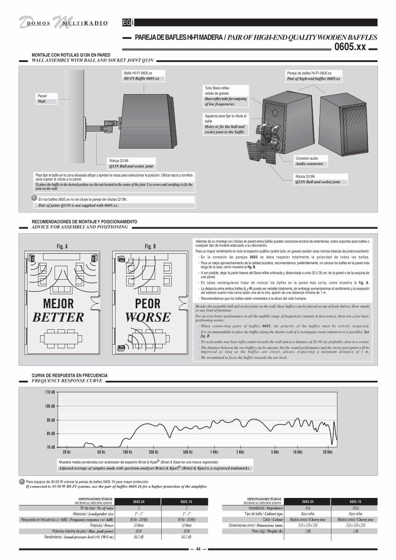


D MM U L T I R A D I OD O M O S
2
ADAPTACION DE MANDOS A MECANISMOS ELECTRICOS DE OTRAS MARCASADAPTING CONTROL UNITS TO ELECTRICAL SWITCHGEAR OF OTHER TRADEMARKS
1
MONTAJE DE LOS MODULOS PARA CAJA UNIVERSAL DE Ø 60 mm. EN LOS NUEVOS EMBELLECEDORES EGiASSEMBLY OF THE MODULES FOR STANDARD FLUSH MOUNTING BOX Ø 60 mm WITH THE NEW EGi FRONT TRIMS
Embellecedor 1801/..Front trim 1801/..
Mando D45UControl unit D45U
Embellecedor 1802/..Front trim 1802/..
Mando D46U ointercomunicador J12UControl unit D46U orintercom unit J12U
Altavoz + rejilla G13U/16Laudspeaker G13U/16
0756
Intercomunicador J12UIntercom unit J12U
Embellecedor 1802/..Front trim 1802/..
Mando D44UControl unit D44U
MONTAJE DE MODULOS PARA CAJA UNIVERSAL DE Ø 60 mm. ASSEMBLY OF THE MODULES FOR STANDARD FLUSH MOUNTING BOX Ø 60 mm.
— 46 —
l
SerieSerie
AdaptaciónFitting
MarcaTrademark
SYSTEM 45AVEMediante bastidor EGi W01S.By means of fitting frame EGi W01S.
SERIES DE MECANISMOS ELECTRICOS ADAPTABLESSERIES OF ELECTRICAL SWITCHGEAR THAT CAN BE INSTALLED WITH EGi
FormaMode
ARSYS
Mediante marco intermedio de BERKER® ref. 1108/.. y marquitoque acompaña al módulo EGi.By means of fitting frame from BERKER® ref. 1108/.. and thefixing frame that comes with the sound module.
G
SerieSerie
AdaptaciónFitting
MarcaTrademark
SERIES DE MECANISMOS ELECTRICOS ADAPTABLESSERIES OF ELECTRICAL SWITCHGEAR THAT CAN BE INSTALLED WITH EGi
FormaMode
BERKERCLIPTEC
Mediante marco intermedio de BERKER® ref. 1109/.. y marquitoque acompaña al módulo EGi.By means of fitting frame from BERKER® ref. 1109/.. and thefixing frame that comes with the sound module.
MODUL 2Mediante marco intermedio EGi ref. WM2B/...By means of fitting frame EGi ref. WM2B/...
SOL TEIDE
BJC
Directa.Directly.
ROOMDirecta.Directly.
IRISMediante adaptador BJC® ref. 18743/...By means of plate from BJC® ref. 18743/...
AURAMediante adaptador BJC® ref. 18743/...By means of plate from BJC® ref. 18743/...
LIGHT(caja Ø 60 mm)
(fitting box Ø 60 mm)
En los mandos, instalación directa o sustituir chasis metálico EGi porconjunto de piezas EGi ref. WL2T y marquito que acompaña almódulo EGi. Utilizar altavoz 2" banda ancha GL2T/16.For the control units, replace the metallic fitting plate of the EGimodule by parts set ref. WL2T. Use wide-band loudspeakerGL2T/16.
BTICINO
LIVING(caja Ø 60 mm)
(fitting box Ø 60 mm)
En los mandos, sustituir chasis metálico EGi por conjunto de piezasEGi ref. WLIT. Utilizar altavoz 2" banda ancha GLIT/16 o GLIT/32.For the control units, replace the metallic fitting plate of the EGimodule by parts set ref. WLIT. Use wide-band loudspeakerGLIT/16 and GLIT/32.En los mandos, sustituir chasis metálico EGi por conjunto de piezasEGi ref. WLIT.1. No es posible la instalación de altavoz 2" en pared.For the control units, replace the metallic fitting plate of the EGimodule by parts set ref. WLIT.1.En los mandos, sustituir chasis metálico EGi por conjunto de piezasEGi ref. WLUT. Utilizar altavoz 2" banda ancha GLUT/16 y GLUT/32.For the control units, replace the metallic fitting plate of the EGimodule by parts set ref. WLUT. Use wide-band loudspeakerGLUT/16 and GLUT/32.
LUNA
EDEMediante marco intermedio de EDE® ref. 70970.By means of fitting frame from EDE® ref. 70970.LOOK 75
Mediante conjuntos EGi ref. W31E/BN o W31E/MF (1 elemento),W32E/BN (2 elementos), W33E/BN (3 elementos).By means of EGi parts set ref. W31E/BN or W31E/MF (1-gang), W32E/BN (2-gang), W33E/BN (3 gang).
EFAPEL
ALFA 3000
Mediante conjuntos EGi ref. WJ1E/BN (1 elemento), WJ2E/BN (2elementos), WJ3E/BN (3 elementos).By means of EGi parts set ref. WJ1E/BN (1-gang), WJ2E/BN(2-gang), WJ3E/BN (3 gang).
APOLO 5000
C
B
A
AH
C
E
DLIVING
(caja de 3 módulos)(fitting box 3 mods.)
B1
Mediante marco intermedio de EGi ref. 0706 y marquito queacompaña al módulo EGi.By means of fitting frame from EGi ref. 0706 and the fixing framethat comes with the sound module.
B
LIGHT(caja Ø 60 mm
y caja de 3 módulos)(fitting box Ø 60 mm
and fitting box 3 mods.)
En los mandos, sustituir chasis metálico EGi por conjunto de piezasEGi ref. WLGT y marquito que acompaña al módulo EGi. Utilizaraltavoz 2" banda ancha GL3T/16 o GL3T/16BN.For the control units, replace the metallic fitting plate of the EGimodule by parts set ref. WLGT. Use wide-band loudspeakerGL3T/16 or GL3T/16BN.
H
C
EUNEA
SCHNEIDERSM 200
En los mandos, sustituir chasis metálico EGi por conjunto de piezasEUNEA® ref. 30582. A continuación utilizar marco intermedio EUNEA®ref. 60412/.. y marquito que acompaña al módulo EGi. Utilizaraltavoz 2" banda ancha 0601.10 ó 0601.12.For the control units, replace the metallic fitting plate of theSCHNEIDER® ref. 30582 and then use fitting frame fromSCHNEIDER® ref. 60412/.. and the fixing frame that comes with theEGi module. Use wide-band loudspeaker 0601.10 or 0601.12.
SM 180
En los mandos, sustituir chasis metálico EGi por conjunto de piezasEGi ref. WSM8/BN, WSM8/BL o WSM8/NE y utilizar el marco interme-dio de EUNEA® ref. 70412.xx. No es posible la instalación dealtavoz 2" en pared.For the control units, replace the metallic fitting plate of the EGimodule by parts set ref. WSM8/BN, WSM8/BL or WSM8/NEand then use fitting frame from SCHNEIDER® ref. 70412.xx.
E
SINTRA
Mediante marcos de GE® ref. SS237 (1 elemento) o DHS 237 (2elementos), tapa para módulos de sonido de GE® ref. DS237 ymarquito que acompaña al módulo EGi.By means of fitting frame from GE® ref. SS237 (1-gang) or DHS237 (2-gang), fitting plate for sound modules ref. GE®, DS237and the fixing frame that comes with the EGi module.
GENERALELECTRIC C
PLAYBUS
En los mandos, sustituir chasis metálico EGi por conjunto de piezasEGi ref. WPLG. Utilizar altavoz 2" banda ancha GP2G/16.For control units, replace the metallic fitting plate ofthe EGi module by the parts set ref. WPLG. Use wide-band loudspeaker GP2G/16.
GEWISS
F
SYSTEM22 EXPO
En los mandos, sustituir chasis metálico EGi por conjunto de piezasEGi ref. W22G. No es posible la instalación de altavoz 2" en pared.For control units, replace the metallic fitting plate ofthe EGi module by the parts set ref. W22G.
I
EVENT
Mediante marcos EGi ref. WEVG/27 (blanco) o WEVG/28 (antracita)y marquito que acompaña al módulo.By means of parts sets EGi ref. WEVG/27 (white) or WEVG/28(antracite).
GIRA
E
F-LINE
Mediante marcos EGi ref. WFLG/.. y marquito que acompaña almódulo.By means of parts sets EGi ref. WFLG/.. and the fixing frame thatcomes with the EGi module.
C
JUNG
CD 500
Mediante marcos intermedios de JUNG® ref. CD EGi o CD EGi WWy marquito que acompaña al módulo EGi.By means of fitting frame from JUNG® ref. CD EGi or CD EGiWW and the fixing frame that comes with the EGi module.
CD 500 PLUS
Mediante marcos intermedios de JUNG® ref. CD EGi o CD EGi WWy marquito que acompaña al módulo EGi.By means of fitting frame from JUNG® ref. CD EGi or CD EGiWW and the fixing frame that comes with the EGi module.
C
ST 550
Mediante marcos intermedios de JUNG® ref. CD EGi o CD EGi WWy marquito que acompaña al módulo EGi.By means of fitting frame from JUNG® ref. CD EGi or CD EGiWW and the fixing frame that comes with the EGi module.
A
UNICA BASICUNICA COLORS
Cortar las patas de fijación interiores del embellecedor EUNEA®UNICA BASIC o EUNEA® UNICA COLORS. A continuación lainstalación es directa. Mejor estética y sujeción mediante marquilloEGi 0707.10 (blanco) y 0707.12 (negro).By means of parts sets 0707.10 (white) and 0707.12 (black) .
EDELSTAHLMediante marco intermedio EGi ref. 002650 (aluminio).By means of fitting frame from EGi ref. 002650 (alluminium).
UNICA PLUSUNICA TOP
Cortar las patas de fijación interiores del embellecedor EUNEA®UNICA PLUS o EUNEA® UNICA TOP. A continuación la instalaciónes directa. Mejor estética y sujeción mediante marquillo EGi 0711.10(blanco) y 0711.12 (negro).By means of parts sets 0711.10 (white) and 0711.12 (black) .
SM 100Directa.Directly.
SM 100 MASTERDirecta.Directly.
A

D MM U L T I R A D I OD O M O S
3
La serie SYSTEM 45 es propiedad de AVE®. / Serie SYSTEM 45 is property of AVE®.Las series ARSYS, B1, CLIPTEC y MODUL 2 son propiedad de BERKER®. / Series ARSYS, B1, CLIPTEC and MODUL 2 are property of BERKER®.Las series SOL TEIDE, ROOM, IRIS, AURA e IBIZA son propiedad de BJC®. / Series SOL TEIDE, ROOM, IRIS, AURA and IBIZA are property of BJC®.Las series LIGHT, LIVING y LUNA son propiedad de BTICINO®. / Series LIGHT, LIVING and LUNA are property of BTICINO®.La serie LOOK 75 es propiedad de EDE®. / Serie LOOK 75 is property of EDE®.Las series ALFA 3000 y APOLO 5000 son propiedad de EFAPEL®. / Series ALFA 3000 and APOLO 5000 are property of EFAPEL®.Las series SM 100, SM 100 MASTER, SM 180, SM 200, UNICA BASIC, UNICA COLORS, UNICA PLUS y UNICA TOP son propiedad de EUNEA®. / Series SM 100, SM 100 MASTER, SM 180, SM 200, UNICA BASIC,UNICA COLORS, UNICA PLUS and UNICA TOP are property of EUNEA®.La serie SINTRA es propiedad de GENERAL ELECTRIC®. / Serie SINTRA is property of GENERAL ELECTRIC®.Las series PLAYBUS y SYSTEM 22 EXPO son propiedad de GEWISS®. / Series PLAYBUS and SYSTEM 22 EXPO are property of GEWISS®.Las series EVENT, EDELSTAHL y F-LINE son propiedad de GIRA®. / Series EVENT, EDELSTAHL and F-LINE are property of GIRA®.Las series CD 500, CD 500 PLUS, ST 550, TOP LINE y LS 990 son propiedad de JUNG®. / Series CD 500, CD 500 PLUS, ST 550, TOP LINE and LS 990 are property of JUNG®.Las series MOSAIC 45, DECOR, GALEA, PRESIDENTE, SUNO y VALENA son propiedad de LEGRAND®. / Series MOSAIC 45, DECOR, GALEA, PRESIDENTE, SUNO and VALENA are property of LEGRAND®.Las series ANTIK, ARTEC, ATELIER, EPOCA, M1 y OCTOCOLOR son propiedad de MERTEN®. / Series ANTIK, ARTEC, ATELIER, EPOCA, M1 and OCTOCOLOR are property of MERTEN®.Las series DA VINCI, PR 20 y PR 20 SOFT son propiedad de NIKO®. / Series DA VINCI, PR 20 and PR 20 SOFT are property of NIKO®.Las series DELTA AMBIENTE, DELTA PROFIL, DELTA LINE, DELTA VITA y DELTA PLUS son propiedad de SIEMENS®. / Series DELTA AMBIENTE, DELTA PROFIL, DELTA LINE, DELTA VITA and DELTAPLUS are property of SIEMENS®.Las series 27, 28, 29, 31, 75, 82 y 88 son propiedad de SIMON®. / Series 27, 28, 29, 31, 75, 82 and 88 are property of SIMON®.Las series IDEA y PLANA son propiedad de VIMAR®. / Series IDEA and PLANA are property of VIMAR®.
AVE®, BERKER®, BJC®, BTICINO®, EDE®, EFAPEL®, EUNEA®, GENERAL ELECTRIC®, GEWISS®, GIRA®, JUNG®, LEGRAND®, MERTEN®, NIKO®, SIEMENS®, SIMON® y VIMAR® son marcas registradas por sus propietarios.AVE®, BERKER®, BJC®, BTICINO®, EDE®, EFAPEL®, EUNEA®, GENERAL ELECTRIC®, GEWISS®, GIRA®, JUNG®, LEGRAND®, MERTEN®, NIKO®, SIEMENS®, SIMON® and VIMAR®are registered trademarks of their owners.
— 47 —
ADAPTACION DE MANDOS A MECANISMOS ELECTRICOS DE OTRAS MARCASADAPTING CONTROL UNITS TO ELECTRICAL SWITCHGEAR OF OTHER TRADEMARKS
MONTAJE DE MODULOS PARA CAJA UNIVERSAL DE Ø 60 mm. ASSEMBLY OF THE MODULES FOR STANDARD FLUSH MOUNTING BOX Ø 60 mm.
l
SerieSerie
AdaptaciónFitting
MarcaTrademark
SERIES DE MECANISMOS ELECTRICOS ADAPTABLESSERIES OF ELECTRICAL SWITCHGEAR THAT CAN BE INSTALLED WITH EGi
FormaMode
SerieSerie
AdaptaciónFitting
MarcaTrademark
SERIES DE MECANISMOS ELECTRICOS ADAPTABLESSERIES OF ELECTRICAL SWITCHGEAR THAT CAN BE INSTALLED WITH EGi
FormaMode
DELTAAMBIENTE
Mediante marco intermedio de EGi ref. WDAS/.. y marquito queacompaña al módulo EGi.By means of fitting frame from EGi ref. WDAS/.. and the fixingframe that comes with the EGi module.
SIMON
27Mediante marco intermedio EGi ref. W27S/..By means of fitting frame EGi ref. W27S/..
SIEMENS
28Mediante marco intermedio EGi ref. W28S/..By means of fitting frame EGi ref. W28S/..
C
EB
29Directa.Directly. A
31
Utilizar tapa ciega 31800.. o adaptador musical ref. 31088.. deSIMON® y marquito que acompaña al módulo EGi.Use 31800.. blind cover or 31088.. music adapter (bothSIMON®) and fixing frame that comes with the EGi module.
C
75Mediante marco intermedio EGi ref. W75S/..By means of fitting frame EGI ref. W75S/.. B
82
Mediante marco intermedio EGi ref. W27S/.. y marco intermedioSIMON® 82 ref. 82088/xx.By means of fitting frame EGI ref. W27S/.. and fitting frameSIMON® 82 ref. 82088/xx.
E88
Mediante marco intermedio de SIMON® ref. 88088 y marquito queacompaña al módulo EGi ref. W27S/..By means of SIMON® ref. 88088 fitting frame and EGi ref.W27S/.. fixing frame.
VIMAR
IDEA(caja Ø 60 mm)
(fitting box Ø 60 mm)
En los mandos, sustituir chasis metálico EGi por conjunto de piezasEGi ref. WID3. Utilizar altavoz 2" banda ancha GI3V/16 y GI3V/32.For the control units, replace the metallic fitting plate of the EGimodule by parts set ref. WID3. Use wide-band loudspeakerGI3V/16 and GI3V/32.
F
En los mandos, sustituir chasis metálico EGi por conjunto de piezasEGi ref. WIDV. No es posible la instalación de altavoz 2" en pared.For the control units, replace the metallic fitting plate of the EGimodule by parts set ref. WIDV.
DELTAPROFIL
Mediante marco intermedio de EGi ref. WDAS/.. y marquito queacompaña al módulo EGi.By means of fitting frame from EGi ref. WDAS/.. and the fixingframe that comes with the EGi module.
DELTALINE
Mediante marco intermedio de EGi ref. 0708.10 y marquito queacompaña al módulo EGi.By means of fitting frame from EGi ref. 0708.10 and the fixingframe that comes with the EGi module.
DELTAVITA
Mediante marco intermedio de EGi ref. 0708.10 y marquito queacompaña al módulo EGi.By means of fitting frame from EGi ref. 0708.10 and the fixingframe that comes with the EGi module.
DELTAPLUS
Mediante marco intermedio de EGi ref. 0708.10 y marquito queacompaña al módulo EGi.By means of fitting frame from EGi ref. 0708.10 and the fixingframe that comes with the EGi module.
IDEA(caja Ø 60 mm
y caja de 3 módulos)(fitting box Ø 60 mm
and fitting box 3 mods.)
En los mandos, sustituir chasis metálico EGi por conjunto de piezasEGi ref. 0710.10 ó 0710.12. No es posible la instalación de altavoz2" en pared.For the control units, replace the metallic fitting plate of the EGimodule by parts set ref. 0710.10 or 0710.12.
IPLANA
EMERTEN
ANTIK
Mediante placa de MERTEN® ref. 0021/.. y aro adaptador deMERTEN® ref. 001900/.. suministrados por GUIJARRO HNOS.By means of plate from MERTEN® ref. 0021/.. and fitting ringfrom MERTEN® ref. 001900/.. (ask EGi for supply).
ATELIER
Mediante placa de MERTEN® ref. 0020/.. y aro adaptador deMERTEN® ref. 001900/.. suministrados por GUIJARRO HNOS.By means of plate from MERTEN® ref. 0020/.. and fitting ringfrom MERTEN® ref. 001900/.. (ask EGi for supply).
EPOCA
Mediante placa de MERTEN® ref. 0020/.. y aro adaptador deMERTEN® ref. 001900/.. suministrados por GUIJARRO HNOS.By means of plate from MERTEN® ref. 0020/.. and fitting ringfrom MERTEN® ref. 001900/.. (ask EGi for supply).
M1
Mediante placa de MERTEN® ref. 0020/.. y aro adaptador deMERTEN® ref. 001900/.. suministrados por GUIJARRO HNOS.By means of plate from MERTEN® ref. 0020/.. and fitting ringfrom MERTEN® ref. 001900/.. (ask EGi for supply).
OCTOCOLOR
Mediante placa de MERTEN® ref. 0026/.. y aro adaptador deMERTEN® ref. 001900/.. suministrados por GUIJARRO HNOS.By means of plate from MERTEN® ref. 0026/.. and fitting ringfrom MERTEN® ref. 001900/.. (ask EGi for supply).
DA VINCI
Mediante marco intermedio de EGi ref. WDVN/.. y marquito queacompaña al módulo EGi.By means of fitting frame from EGi ref. WDVN/.. and the fixingframe that comes with the EGi module.
NIKO CPR 20
Mediante marco intermedio de EGi ref. W20N/.. y marquito queacompaña al módulo EGi.By means of fitting frame from EGi ref. W20N/.. and the fixingframe that comes with the EGi module.
PR 20 SOFT
Mediante marco intermedio de EGi ref. WSON y marquito queacompaña al módulo EGi.By means of fitting frame from EGi ref. WSON and the fixingframe that comes with the EGi module.
MOSAIC 45Directa.Directly. A
DECOR
Mediante marco intermedio de EGi ref. WDEL y marquito queacompaña al módulo EGi.By means of fitting frame from EGi ref. WDEL and the fixingframe that comes with the EGi module.
C
LEGRAND
GALEA
Mediante marco intermedio de EGi ref. 0702.10 ó 0702.12 ymarquito que acompaña al módulo EGi.By means of fitting frame from EGi ref. 0702.10 or 0702.12 andthe fixing frame that comes with the EGi module.
PRESIDENTEMediante marco intermedio de EGi ref. WPRL y marquito queacompaña al módulo EGi.By means of parts set EGi ref. WPRL.
E
CSUNO
Mediante marco intermedio de EGi ref. 0709.10 y 0709.12 ymarquito que con él se acompaña.By means of parts set EGi ref. 0709.10 or 0709.12.
VALENAMediante marco intermedio de EGi ref. 0705.10 y 0705.12 ymarquito que con él se acompaña.By means of parts set EGi ref. 0705.10 or 0705.12.
JUNG
TOP LINE
Quitar del marco exterior de JUNG® ref. TL_98_x.. el tarjetero quelleva dos tornillos. A continuación, utilizar marco intermedio deJUNG® ref. TL 961 Z WW y marquito que acompaña al módulo EGi.Remove from the wall frame from JUNG® ref. TL_98_x.. thesymbol holding plate (that is fixed with 2 screws). Then usefitting plate from JUNG® ref. TL 961 Z WW and small fixingframe that comes with the EGi module.
LS 990
Mediante marcos intermedios de JUNG® ref. LS961-ZWW o LS-961-ZWW y marquito que acompaña al módulo EGi.By means of fitting frame from JUNG® ref. LS961-ZWW or LS-961-ZWW and the fixing frame that comes with the EGi module.
C
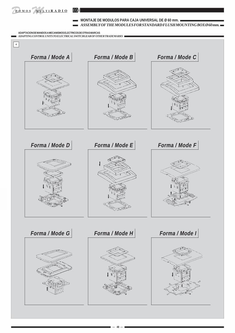
D MM U L T I R A D I OD O M O S
— 48 —
ADAPTACION DE MANDOS A MECANISMOS ELECTRICOS DE OTRAS MARCASADAPTING CONTROL UNITS TO ELECTRICAL SWITCHGEAR OF OTHER TRADEMARKS
MONTAJE DE MODULOS PARA CAJA UNIVERSAL DE Ø 60 mm. ASSEMBLY OF THE MODULES FOR STANDARD FLUSH MOUNTING BOX Ø 60 mm.
l
4
Forma / Mode A Forma / Mode B Forma / Mode C
Forma / Mode D Forma / Mode E Forma / Mode F
Forma / Mode G Forma / Mode H Forma / Mode I