manual de usuario se-1520
DESCRIPTION
Manula Spotchem ELTRANSCRIPT


SE-1520 ■ 1
Premise
This manual contains important information on the functions of the SPOTCHEM EL SE-1520
This manual is issued by : ARKRAY, Inc.Read carefully prior to starting up the unit.It is recommended to retain this manual for future use.
This product conforms to the EMC Standard EN61326-2-6: 2006.Class of emission: CISPR 11 Class AThis instrument is for veterinary use only.
This product conforms to European Directive 2006/95/EC and 2004/108/EC
NOTE: This instrument has been tested and found to comply with the limits for a Class A digital device, pursuant to part 15 of the FCC Rules. These limits are designed to provide reasonable protection against harmful interference when the instrument is operated in a commercial environment. This instrument generates, uses, and can radiate radio frequency energy and, if not installed and used in accordance with the reference manual, may cause harmful interference to radio communications.Operation of this instrument in a residential area is likely to cause harmful interference in which case the user will be required to correct the interference at his own expense.
The electromagnetic environment should be evaluated prior to operation of the device. Do not use this device in close proximity to sources of strong electromagnetic radiation, as these may interfere with the proper operation.
2 ■ SE-1520
Introduction
The SPOTCHEM EL SE-1520 is an electrolyte measuring system.
Before operating the SE-1520, please read this manual carefully.This manual contains outlines, instructions for the operation, maintenance and troubleshooting for the SPOTCHEM EL SE-1520.Follow the instructions in this manual in order not to defeat the purpose of protective features of the instrument.Please retain this manual for future reference.
● Always be careful when handling blood samples. Incorrect or imprecise procedures may result in exposure to pathogenic microbes.
● This system must be operated only by those trained in proper procedures for clinical testing and handling of hazardous waste. Trained personnel must assist anyone who operates this system for the first time.
● If blood sample is spilt, the user has responsibility for carrying out appropriate decontamination.
● Never touch the E-Plate, pipetting tip or other places where sample residue may adhere with bare hands. When performing maintenance, always wear protective gloves to prevent exposure to pathogenic microbes.
● Separate used samples, E-Plate, pipetting tips and cleaning equipment from general waste and dispose of them according to local regulations on biohazardous waste.
● This system may become infectious in the course of use. Discard the product in accordance with local regulations for biohazardous waste.
All rights reserved. Reproduction of this manual is prohibited.The contents of this manual are subject to change without prior notice.Although we take all possible measures to ensure the contents of this manual, please notify your distributor when you have questions, or find errors or omission.©2011 ARKRAY, Inc.
Before using any cleaning or decontamination methods except those recommended by the manufacturer, users should check with the manufacturer that the proposed method will not damage the instrument.
SE-1520 ■ �
Notation
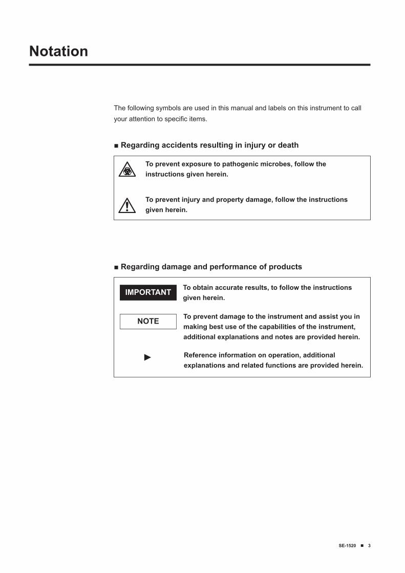
The following symbols are used in this manual and labels on this instrument to call your attention to specific items.
■ Regarding damage and performance of products
To obtain accurate results, to follow the instructions given herein.
IMPORTANT
To prevent damage to the instrument and assist you in making best use of the capabilities of the instrument, additional explanations and notes are provided herein.
NOTE
Reference information on operation, additional explanations and related functions are provided herein.
■ Regarding accidents resulting in injury or death
To prevent exposure to pathogenic microbes, follow the instructions given herein.
To prevent injury and property damage, follow the instructions given herein.
►
� ■ SE-1520
Caution Labels
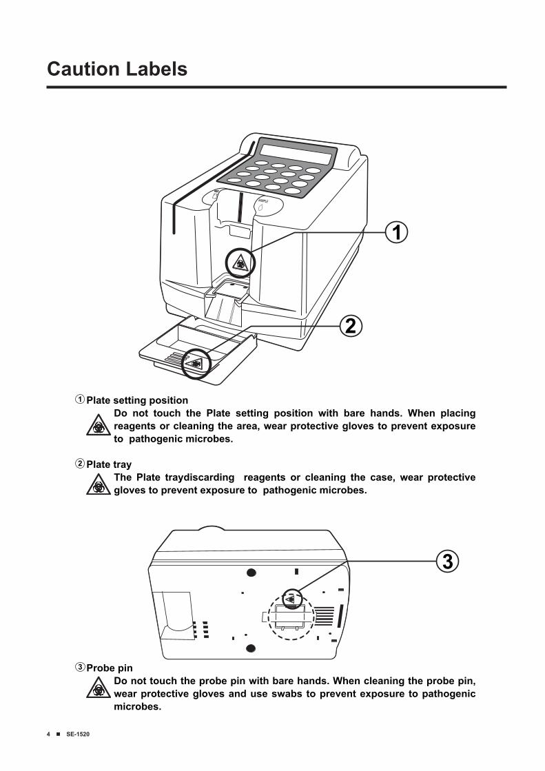
1 Plate setting positionDo not touch the Plate setting position with bare hands. When placing reagents or cleaning the area, wear protective gloves to prevent exposure to pathogenic microbes.
Plate trayThe Plate traydiscarding reagents or cleaning the case, wear protective gloves to prevent exposure to pathogenic microbes.
2
Probe pinDo not touch the probe pin with bare hands. When cleaning the probe pin, wear protective gloves and use swabs to prevent exposure to pathogenic microbes.
1
3
2
3
SE-1520 ■ 5
Chapter 1Introduction
Electrolyte measuring system, SE-1520 Operating Manual
Contents
Premise .....................................................................................................1Introduction .............................................................................................2Notation .....................................................................................................3Caution Labels ........................................................................................4Contents ....................................................................................................5
1-1 Outline ..........................................................................................1-21-1-1 Features ..............................................................................1-21-1-2 Measurement Types ............................................................1-31-1-3 Measurement Principles .....................................................1-31-1-4 Specifications ......................................................................1-4
1-2 Shipping Carton .......................................................................1-51-2-1 Shipping Carton (Analyzer and Accessories) ......................1-5
1-3 Parts Description and Function ...........................................1-61-3-1 Front of the Analyzer ...........................................................1-61-3-2 Operator Panel ....................................................................1-71-3-3 Back of the Analyzer ...........................................................1-81-3-4 Twin Pipette ........................................................................1-91-3-5 Twin Pipette II ...................................................................1-10
1-4 Installation ................................................................................1-111-4-1 Cautions ............................................................................1-111-4-2 Setting Up .........................................................................1-131-4-3 First Operation after Installation ........................................1-151-4-4 Precautions in Instrument Relocation ...............................1-16
2-1 Outline ..........................................................................................2-22-1-1 Operating Procedures .........................................................2-22-1-2 Exclusive E-Plate ................................................................2-32-1-3 Measurement ......................................................................2-32-1-4 Calibration ...........................................................................2-4
2-2 Cautions .......................................................................................2-52-2-1 Cautions on Operation ........................................................2-52-2-2 Handling Samples ...............................................................2-62-2-3 Handling Exclusive E-Plate .................................................2-62-2-4 Handling Magnetic Card .....................................................2-72-2-5 Handling Twin Pipette and Twin Pipette II ...........................2-72-2-6 Handling Reference Solution ..............................................2-9
2-3 Preparation ...............................................................................2-102-3-1 Preparation .......................................................................2-102-3-2 Startup ..............................................................................2-112-3-3 Checks before Measurement ............................................2-122-3-4 Preparation of Samples ....................................................2-142-3-5 Suction of Reference Solution and Samples ....................2-15
Chapter 2Measurement
� ■ SE-1520
2-4 Measurement ............................................................................2-182-4-1 Normal Measurement .......................................................2-18
2-5 Calibration .................................................................................2-232-5-1 Overview ...........................................................................2-232-5-2 Magnetic Card Calibration ................................................2-23
2-6 Measurement Result ..............................................................2-252-6-1 Printing the Normal Measurement Results .......................2-25
3-1 Overview ......................................................................................3-23-1-1 Contents of Each Menu ......................................................3-2
3-2 Measurement Results Menu ..................................................3-43-2-1 Printing Measurement Results ............................................3-43-2-2 Transmitting Measurement Results ....................................3-63-2-3 Deleting Measurement Results ...........................................3-83-2-4 Wildcards ............................................................................3-9
3-3 Parameter Menu ......................................................................3-103-3-1 Printing Parameters ..........................................................3-103-3-2 Entering Parameters .........................................................3-123-3-3 Initializing Parameters .......................................................3-14
3-4 Maintenance Menu .................................................................3-163-4-1 Cleaning the Probe ...........................................................3-163-4-2 Cleaning the Table ............................................................3-163-4-3 Check Measurement .........................................................3-16
�-5 Mode Menu ................................................................................3-173-5-1 Survey Mode .....................................................................3-17
3-6 Built-in Clock Adjustment ....................................................3-18
4-1 Outline ..........................................................................................4-24-1-1 Frequency of Maintenance .................................................4-2
4-2 Daily Maintenance ....................................................................4-34-2-1 Cleaning the Plate Tray .......................................................4-34-2-2 Cleaning the Plate Transfer Part .........................................4-3
4-3 Periodical Maintenance ..........................................................4-44-3-1 Replacement of Thermal Printer Paper ...............................4-44-3-2 Cleaning the Probe .............................................................4-64-3-3 Cleaning the Twin Pipette II ................................................4-84-3-4 Replacement of Nozzle O-ring ............................................4-9
5-1 Error Messages .........................................................................5-25-2 Trouble Messages ....................................................................5-5
6-1 Transmission Specifications ................................................6-26-1-1 External Output Format .......................................................6-26-1-2 Block Structure ....................................................................6-36-1-3 Format of Measurement Results .........................................6-4
6-2 After-sales Service ...................................................................6-5
Chapter 3Sub Menu
Chapter 4Maintenance
Chapter 5Troubleshooting
Chapter 6Appendix
SE-1520 ■ 1-1
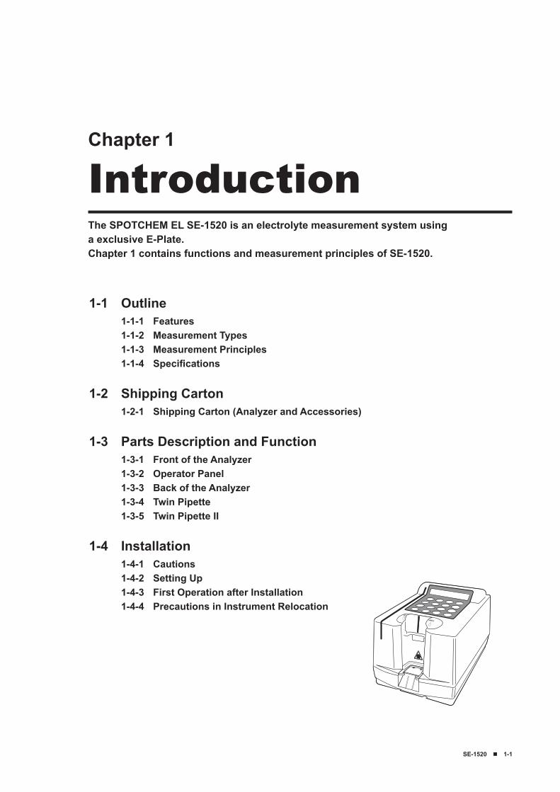
The SPOTCHEM EL SE-1520 is an electrolyte measurement system using a exclusive E-Plate.Chapter 1 contains functions and measurement principles of SE-1520.
Chapter 1
Introduction
1-1 Outline1-1-1 Features1-1-2 Measurement Types1-1-3 Measurement Principles1-1-4 Specifications
1-2 Shipping Carton1-2-1 Shipping Carton (Analyzer and Accessories)
1-3 Parts Description and Function1-3-1 Front of the Analyzer1-3-2 Operator Panel1-3-3 Back of the Analyzer1-3-4 Twin Pipette1-3-5 Twin Pipette II
1-4 Installation1-4-1 Cautions1-4-2 Setting Up1-4-3 First Operation after Installation1-4-4 Precautions in Instrument Relocation
1-2 ■ SE-1520
Chapter 1 Introduction
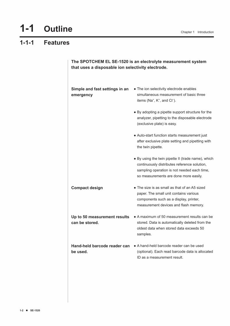
Simple and fast settings in an emergency
Compact design
Up to 50 measurement results can be stored.
Hand-held barcode reader can be used.
The ion selectivity electrode enables simultaneous measurement of basic three items (Na+, K+, and Cl−).
By adopting a pipette support structure for the analyzer, pipetting to the disposable electrode (exclusive plate) is easy.
Auto-start function starts measurement just after exclusive plate setting and pipetting with the twin pipette.
By using the twin pipette II (trade name), which continuously distributes reference solution, sampling operation is not needed each time, so measurements are done more easily.
The size is as small as that of an A5 sized paper. The small unit contains various components such as a display, printer, measurement devices and flash memory.
A maximum of 50 measurement results can be stored. Data is automatically deleted from the oldest data when stored data exceeds 50 samples.
A hand-held barcode reader can be used (optional). Each read barcode data is allocated ID as a measurement result.
●
●
●
●
●
●
●
The SPOTCHEM EL SE-1520 is an electrolyte measurement system that uses a disposable ion selectivity electrode.
1-1 Outline1-1-1 Features
SE-1520 ■ 1-�
Chapter 1 Introduction
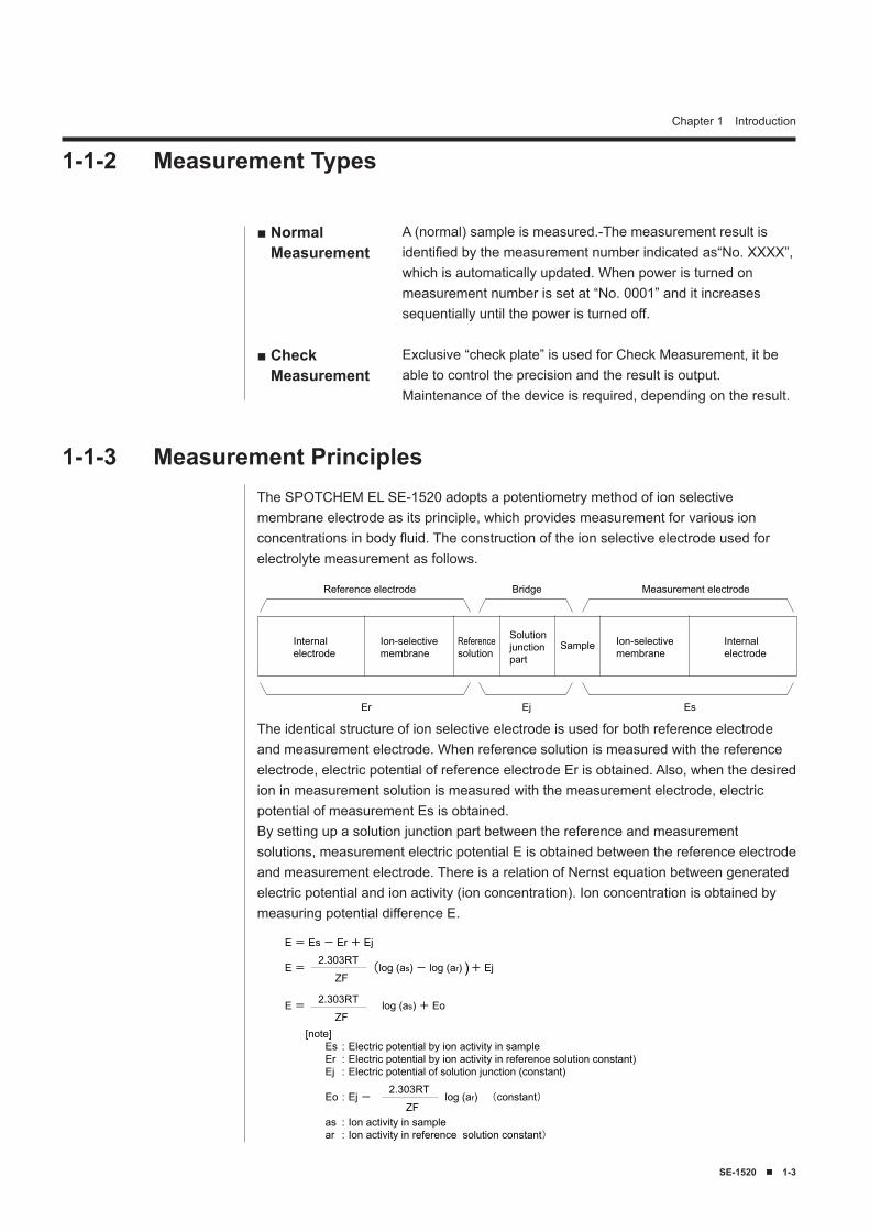
The SPOTCHEM EL SE-1520 adopts a potentiometry method of ion selective membrane electrode as its principle, which provides measurement for various ion concentrations in body fluid. The construction of the ion selective electrode used for electrolyte measurement as follows.
1-1-3 Measurement Principles
■ Normal Measurement
■ Check Measurement
A (normal) sample is measured.-The measurement result is identified by the measurement number indicated as“No. XXXX”, which is automatically updated. When power is turned on measurement number is set at “No. 0001” and it increases sequentially until the power is turned off.
Exclusive “check plate” is used for Check Measurement, it be able to control the precision and the result is output. Maintenance of the device is required, depending on the result.
1-1-2 Measurement Types
Internalelectrode
Internalelectrode
Ion-selectivemembrane
Ion-selectivemembrane
Referencesolution
SampleSolutionjunctionpart
Reference electrode Bridge Measurement electrode
Er Ej Es
The identical structure of ion selective electrode is used for both reference electrode and measurement electrode. When reference solution is measured with the reference electrode, electric potential of reference electrode Er is obtained. Also, when the desired ion in measurement solution is measured with the measurement electrode, electric potential of measurement Es is obtained.By setting up a solution junction part between the reference and measurement solutions, measurement electric potential E is obtained between the reference electrode and measurement electrode. There is a relation of Nernst equation between generated electric potential and ion activity (ion concentration). Ion concentration is obtained by measuring potential difference E.
E = Es - Er + Ej
E = log (as) - log (ar) + Ej
E = log (as) + Eo
ZF
2.303RT
ZF
2.303RT
ZF
2.303RT
[note] Es : Electric potential by ion activity in sample Er : Electric potential by ion activity in reference solution constant) Ej : Electric potential of solution junction (constant)
Eo : Ej - log (ar) (constant)
as : Ion activity in sample ar : Ion activity in reference solution constant)
( )
1-� ■ SE-1520
Chapter 1 Introduction
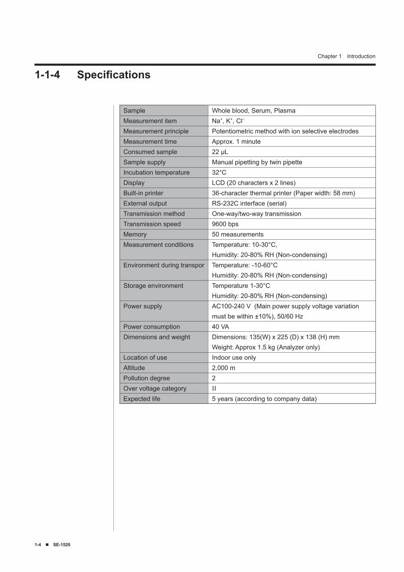
1-1-4 Specifications
Sample Whole blood, Serum, PlasmaMeasurement item Na+, K+, Cl−
Measurement principle Potentiometric method with ion selective electrodesMeasurement time Approx. 1 minuteConsumed sample 22 μLSample supply Manual pipetting by twin pipetteIncubation temperature 32°CDisplay LCD (20 characters x 2 lines)Built-in printer 36-character thermal printer (Paper width: 58 mm)External output RS-232C interface (serial)Transmission method One-way/two-way transmissionTransmission speed 9600 bpsMemory 50 measurementsMeasurement conditions Temperature: 10-30°C,
Humidity: 20-80% RH (Non-condensing)Environment during transpor Temperature: -10-60°C
Humidity: 20-80% RH (Non-condensing)Storage environment Temperature 1-30°C
Humidity: 20-80% RH (Non-condensing)Power supply AC100-240 V (Main power supply voltage variation
must be within ±10%), 50/60 HzPower consumption 40 VADimensions and weight Dimensions: 135(W) x 225 (D) x 138 (H) mm
Weight: Approx 1.5 kg (Analyzer only)Location of use Indoor use onlyAltitude 2,000 mPollution degree 2Over voltage category IIExpected life 5 years (according to company data)
SE-1520 ■ 1-5
Chapter 1 Introduction1-2 Shipping Carton 1-2-1 Shipping Carton (Analyzer and Accessories)
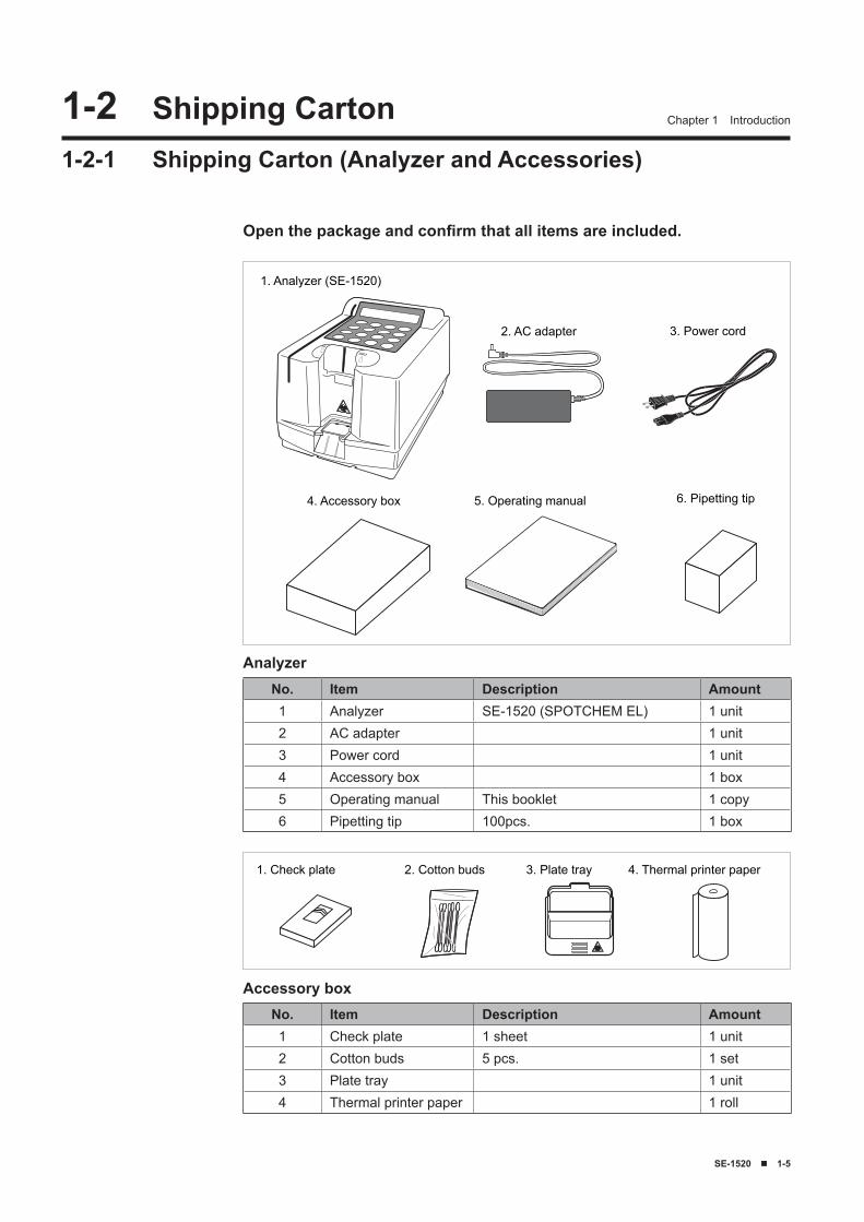
1. Analyzer (SE-1520)
4. Accessory box 5. Operating manual 6. Pipetting tip
2. AC adapter 3. Power cord
Open the package and confirm that all items are included.
3. Plate tray1. Check plate 2. Cotton buds 4. Thermal printer paper
Analyzer
Accessory boxNo. Item Description Amount1 Check plate 1 sheet 1 unit2 Cotton buds 5 pcs. 1 set3 Plate tray 1 unit4 Thermal printer paper 1 roll
No. Item Description Amount1 Analyzer SE-1520 (SPOTCHEM EL) 1 unit2 AC adapter 1 unit3 Power cord 1 unit4 Accessory box 1 box5 Operating manual This booklet 1 copy6 Pipetting tip 100pcs. 1 box
1-� ■ SE-1520
Chapter 1 Introduction
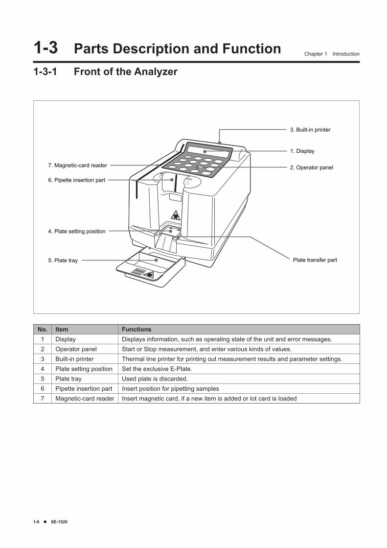
3. Built-in printer
1. Display
2. Operator panel
5. Plate tray
4. Plate setting position
6. Pipette insertion part
7. Magnetic-card reader
Plate transfer part
1-� Parts Description and Function1-3-1 Front of the Analyzer
No. Item Functions1 Display Displays information, such as operating state of the unit and error messages.2 Operator panel Start or Stop measurement, and enter various kinds of values.3 Built-in printer Thermal line printer for printing out measurement results and parameter settings.4 Plate setting position Set the exclusive E-Plate.5 Plate tray Used plate is discarded.6 Pipette insertion part Insert position for pipetting samples7 Magnetic-card reader Insert magnetic card, if a new item is added or lot card is loaded
SE-1520 ■ 1-7
Chapter 1 Introduction
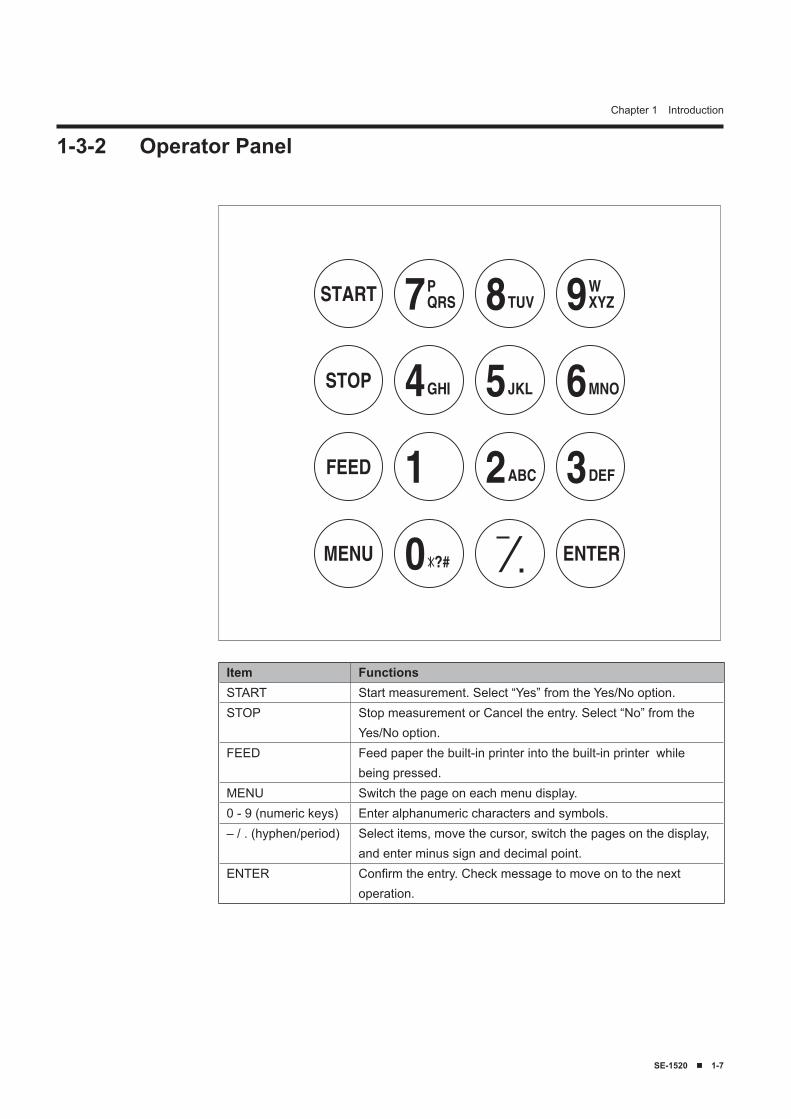
1-3-2 Operator Panel
Item FunctionsSTART Start measurement. Select “Yes” from the Yes/No option.STOP Stop measurement or Cancel the entry. Select “No” from the
Yes/No option.FEED Feed paper the built-in printer into the built-in printer while
being pressed.MENU Switch the page on each menu display.0 - 9 (numeric keys) Enter alphanumeric characters and symbols.– / . (hyphen/period) Select items, move the cursor, switch the pages on the display,
and enter minus sign and decimal point.ENTER Confirm the entry. Check message to move on to the next
operation.
1-8 ■ SE-1520
Chapter 1 Introduction
1. Power switch
2. Terminal
3. RS-232C
4. CONT.
5. B.C.R.
6. Paper cover
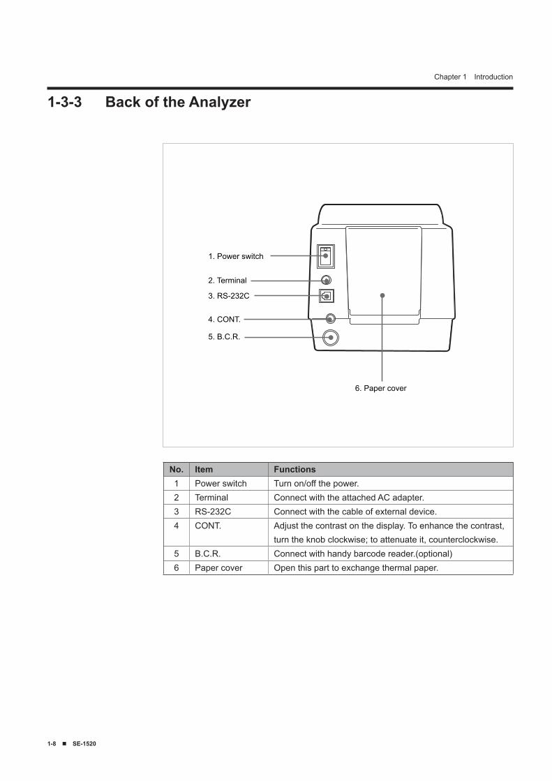
1-3-3 Back of the Analyzer
No. Item Functions1 Power switch Turn on/off the power.2 Terminal Connect with the attached AC adapter.3 RS-232C Connect with the cable of external device.4 CONT. Adjust the contrast on the display. To enhance the contrast,
turn the knob clockwise; to attenuate it, counterclockwise.5 B.C.R. Connect with handy barcode reader.(optional)6 Paper cover Open this part to exchange thermal paper.
SE-1520 ■ 1-9
Chapter 1 Introduction
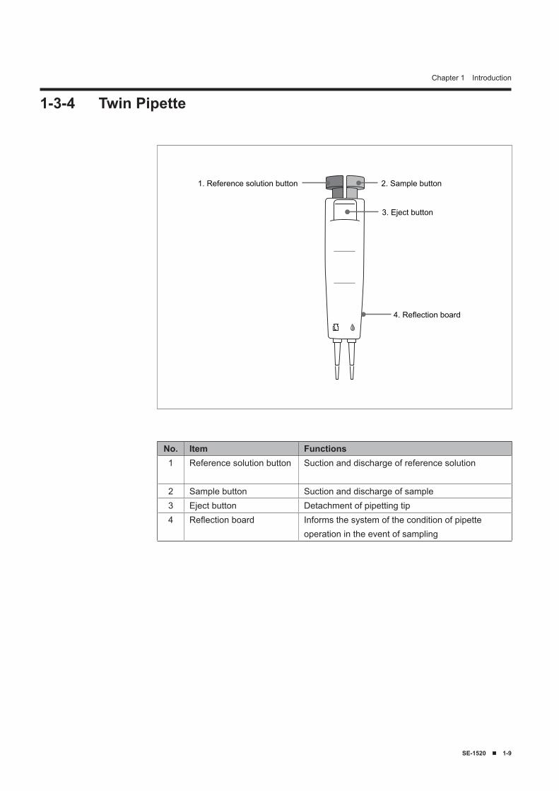
1-3-4 Twin Pipette
1. Reference solution button 2. Sample button
3. Eject button
4. Reflection board
No. Item Functions1 Reference solution button Suction and discharge of reference solution
2 Sample button Suction and discharge of sample3 Eject button Detachment of pipetting tip4 Reflection board Informs the system of the condition of pipette
operation in the event of sampling
1-10 ■ SE-1520
Chapter 1 Introduction
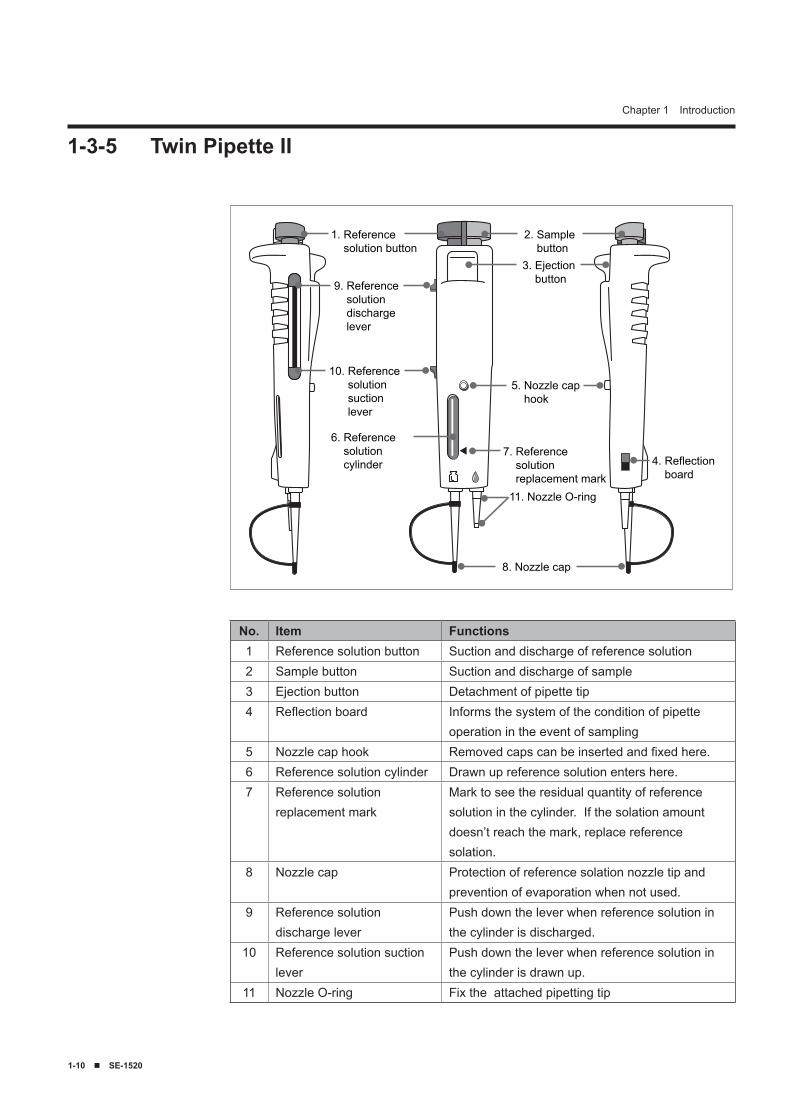
1-3-5 Twin Pipette II
1. Reference solution button
2. Sample button3. Ejection button
5. Nozzle cap hook
8. Nozzle cap
9. Reference solution discharge lever
10. Reference solution suction lever
6. Reference solution cylinder
7. Reference solution replacement mark11. Nozzle O-ring
4. Reflection board
No. Item Functions1 Reference solution button Suction and discharge of reference solution2 Sample button Suction and discharge of sample3 Ejection button Detachment of pipette tip4 Reflection board Informs the system of the condition of pipette
operation in the event of sampling5 Nozzle cap hook Removed caps can be inserted and fixed here.6 Reference solution cylinder Drawn up reference solution enters here.7 Reference solution
replacement markMark to see the residual quantity of reference solution in the cylinder. If the solation amount doesn’t reach the mark, replace reference solation.
8 Nozzle cap Protection of reference solation nozzle tip and prevention of evaporation when not used.
9 Reference solution discharge lever
Push down the lever when reference solution in the cylinder is discharged.
10 Reference solution suction lever
Push down the lever when reference solution in the cylinder is drawn up.
11 Nozzle O-ring Fix the attached pipetting tip
SE-1520 ■ 1-11
Chapter 1 Introduction
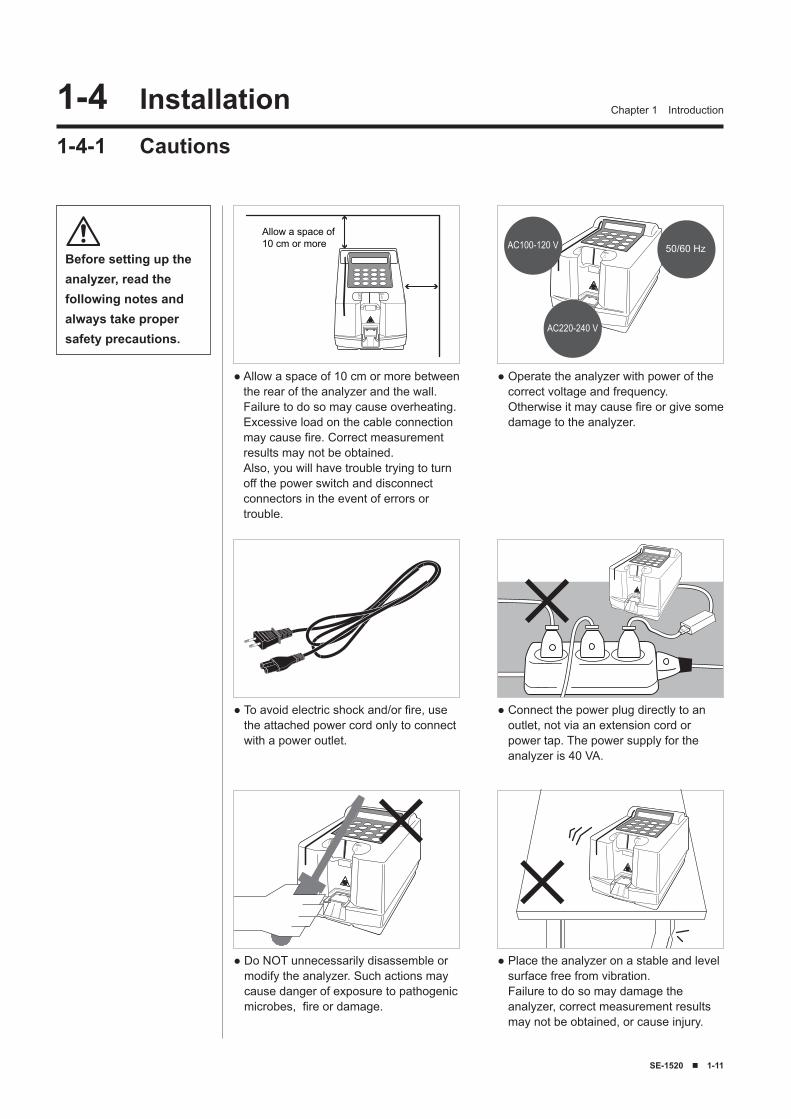
Before setting up the analyzer, read the following notes and always take proper safety precautions.
Allow a space of10 cm or more
● Allow a space of 10 cm or more between the rear of the analyzer and the wall. Failure to do so may cause overheating. Excessive load on the cable connection may cause fire. Correct measurement results may not be obtained. Also, you will have trouble trying to turn off the power switch and disconnect connectors in the event of errors or trouble.
AC100-120 V
AC220-240 V
50/60 Hz
● Operate the analyzer with power of the correct voltage and frequency. Otherwise it may cause fire or give some damage to the analyzer.
● Do NOT unnecessarily disassemble or modify the analyzer. Such actions may cause danger of exposure to pathogenic microbes, fire or damage.
● Place the analyzer on a stable and level surface free from vibration. Failure to do so may damage the analyzer, correct measurement results may not be obtained, or cause injury.
● To avoid electric shock and/or fire, use the attached power cord only to connect with a power outlet.
● Connect the power plug directly to an outlet, not via an extension cord or power tap. The power supply for the analyzer is 40 VA.
1-� Installation1-4-1 Cautions
1-12 ■ SE-1520
Chapter 1 Introduction
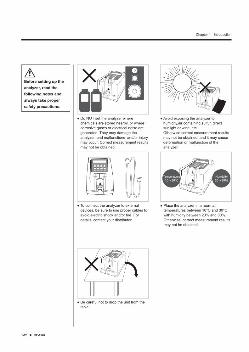
● Do NOT set the analyzer where chemicals are stored nearby, or where corrosive gases or electrical noise are generated. They may damage the analyzer, and malfunctions and/or injury may occur. Correct measurement results may not be obtained.
● Avoid exposing the analyzer to humidity,air containing sulfur, direct sunlight or wind, etc. Otherwise correct measurement results may not be obtained, and it may cause deformation or malfunction of the analyzer.
● To connect the analyzer to external devices, be sure to use proper cables to avoid electric shock and/or fire. For details, contact your distributor.
Temperatures10~30°C
Humidity20~80%
● Place the analyzer in a room at temperatures between 10°C and 30°C with humidity between 20% and 80%. Otherwise, correct measurement results may not be obtained.
Before setting up the analyzer, read the following notes and always take proper safety precautions.
● Be careful not to drop the unit from the table.
SE-1520 ■ 1-1�
Chapter 1 Introduction
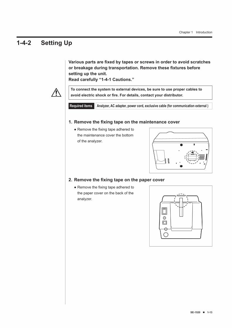
Remove the fixing tape on the paper cover2.Remove the fixing tape adhered to the paper cover on the back of the analyzer.
●
Various parts are fixed by tapes or screws in order to avoid scratches or breakage during transportation. Remove these fixtures before setting up the unit.Read carefully “1-4-1 Cautions.”
To connect the system to external devices, be sure to use proper cables to avoid electric shock or fire. For details, contact your distributor.
Required items Analyzer, AC adapter, power cord, exclusive cable (for communication external )
Remove the fixing tape on the maintenance cover1.Remove the fixing tape adhered to the maintenance cover the bottom of the analyzer.
●
1-4-2 Setting Up
1-1� ■ SE-1520
Chapter 1 Introduction
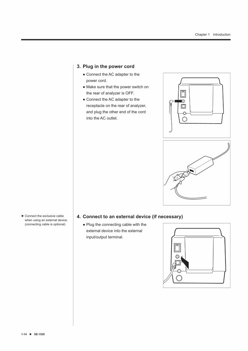
Plug in the power cord3.Connect the AC adapter to the power cord.Make sure that the power switch on the rear of analyzer is OFF.Connect the AC adapter to the receptacle on the rear of analyzer, and plug the other end of the cord into the AC outlet.
●
●
●
Connect to an external device (if necessary)4.Plug the connecting cable with the external device into the external input/output terminal.
●
Connect the exclusive cable when using an external device. (connecting cable is optional)
►
SE-1520 ■ 1-15
Chapter 1 Introduction
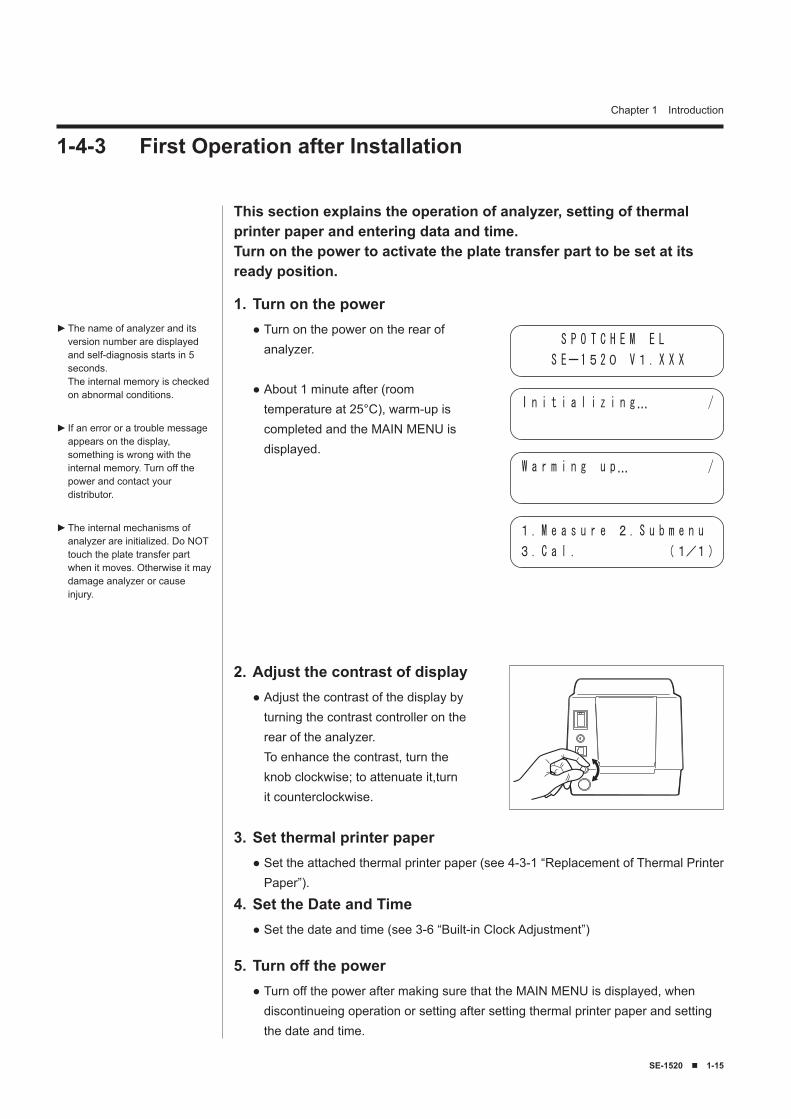
This section explains the operation of analyzer, setting of thermal printer paper and entering data and time.Turn on the power to activate the plate transfer part to be set at its ready position.
Turn on the power1.Turn on the power on the rear of analyzer.
About 1 minute after (room temperature at 25°C), warm-up is completed and the MAIN MENU is displayed.
●
●
Adjust the contrast of display2.Adjust the contrast of the display by turning the contrast controller on the rear of the analyzer. To enhance the contrast, turn the knob clockwise; to attenuate it,turn it counterclockwise.
●
The name of analyzer and its version number are displayed and self-diagnosis starts in 5 seconds. The internal memory is checked on abnormal conditions.
If an error or a trouble message appears on the display, something is wrong with the internal memory. Turn off the power and contact your distributor.
The internal mechanisms of analyzer are initialized. Do NOT touch the plate transfer part when it moves. Otherwise it may damage analyzer or cause injury.
►
►
►
Set the Date and Time4.Set the date and time (see 3-6 “Built-in Clock Adjustment”)●
Turn off the power5.Turn off the power after making sure that the MAIN MENU is displayed, when discontinueing operation or setting after setting thermal printer paper and setting the date and time.
●
Set thermal printer paper3.Set the attached thermal printer paper (see 4-3-1 “Replacement of Thermal Printer Paper”).
●
S P O T C H E M E L
S Eー1520 V1. X X X
I n i t i a l i z i n g… /
W a r m i n g u p… /
1. M e a s u r e 2. S u b m e n u
3. C a l . (1/1)
1-4-3 First Operation after Installation
1-1� ■ SE-1520
Chapter 1 Introduction
Read the precautions below carefully and always be mindful of safety when transporting the system.
Turn off the power and disconnect the power cable before transporting the system. Failure to do so may cause system malfunction.
When transporting the system, handle the system with both hands and avoid exposing the system to impacts or vibrations. Failure to do so may cause system malfunction.
Remove the waste tray before transporting the system. Accidental detachment of the waste tray or waste reagent on the tray may cause pathogenic microbial contamination.
●
●
●
1-4-4 Precautions in Instrument Relocation
SE-1520 ■ 2-1
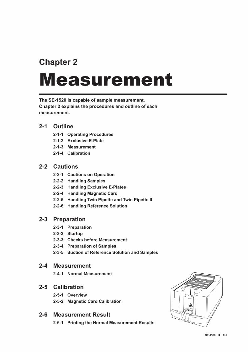
The SE-1520 is capable of sample measurement.Chapter 2 explains the procedures and outline of each measurement.
Chapter 2
Measurement
2-1 Outline2-1-1 Operating Procedures2-1-2 Exclusive E-Plate2-1-3 Measurement2-1-4 Calibration
2-2 Cautions2-2-1 Cautions on Operation2-2-2 Handling Samples2-2-3 Handling Exclusive E-Plates2-2-4 Handling Magnetic Card2-2-5 Handling Twin Pipette and Twin Pipette II2-2-6 Handling Reference Solution
2-3 Preparation2-3-1 Preparation2-3-2 Startup2-3-3 Checks before Measurement2-3-4 Preparation of Samples2-3-5 Suction of Reference Solution and Samples
2-4 Measurement2-4-1 Normal Measurement
2-5 Calibration2-5-1 Overview2-5-2 Magnetic Card Calibration
2-6 Measurement Result2-6-1 Printing the Normal Measurement Results
2-2 ■ SE-1520
Chapter 2 Measurement
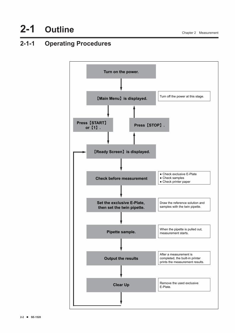
Pipette sample.
【Ready Screen】is displayed.
【Main Menu】is displayed.
Turn on the power.
Press【START】or【1】. Press【STOP】.
Turn off the power at this stage.
Output the results
Clear Up
Set the exclusive E-Plate, then set the twin pipette.
Draw the reference solution and samples with the twin pipette.
When the pipette is pulled out, measurement starts.
After a measurement is completed, the built-in printer prints the measurement results.
Remove the used exclusive E-Plate.
Check before measurement● Check exclusive E-Plate● Check samples● Check printer paper
2-1 Outline2-1-1 Operating Procedures
SE-1520 ■ 2-�
Chapter 2 Measurement
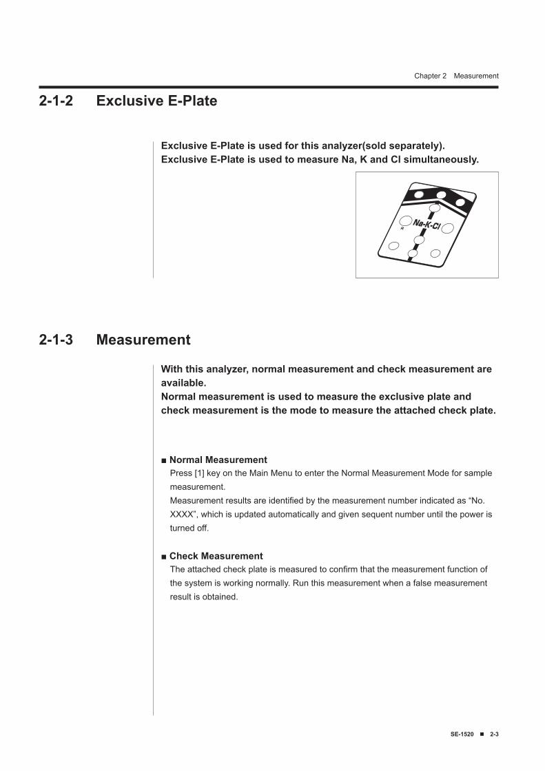
Exclusive E-Plate is used for this analyzer(sold separately).Exclusive E-Plate is used to measure Na, K and Cl simultaneously.
■ Normal MeasurementPress [1] key on the Main Menu to enter the Normal Measurement Mode for sample measurement.Measurement results are identified by the measurement number indicated as “No. XXXX”, which is updated automatically and given sequent number until the power is turned off.
■ Check MeasurementThe attached check plate is measured to confirm that the measurement function of the system is working normally. Run this measurement when a false measurement result is obtained.
2-1-2 Exclusive E-Plate
With this analyzer, normal measurement and check measurement are available.Normal measurement is used to measure the exclusive plate and check measurement is the mode to measure the attached check plate.
2-1-3 Measurement
2-� ■ SE-1520
Chapter 2 Measurement
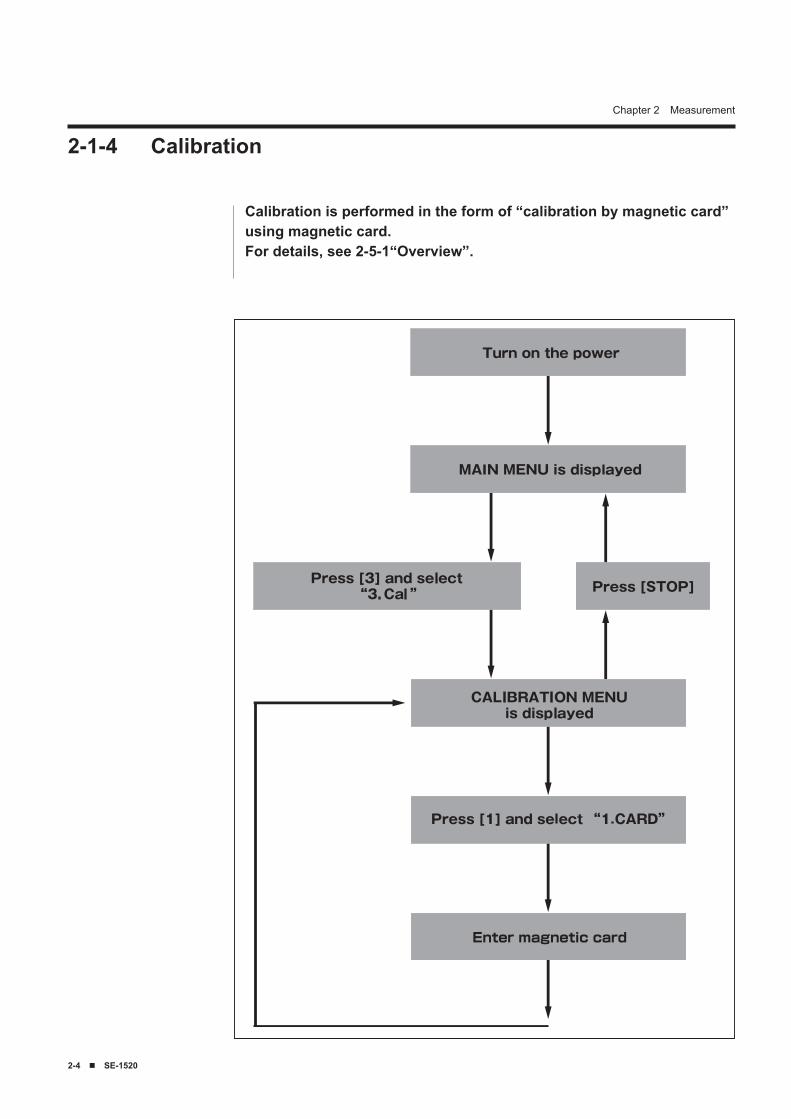
2-1-4 Calibration
Calibration is performed in the form of “calibration by magnetic card”using magnetic card.For details, see 2-5-1“Overview”.
SE-1520 ■ 2-5
Chapter 2 Measurement2-2 Cautions2-2-1 Cautions on Operation
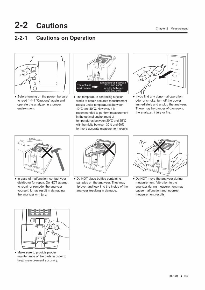
● Before turning on the power, be sure to read 1-4-1 “Cautions” again and operate the analyzer in a proper environment.
Temperatures between 20°C and 25°C
Humidity between 30% and 60%
The optimal environment
● The temperature controlling function works to obtain accurate measurement results under temperatures between 10°C and 30°C. However, it is recommended to perform measurement in the optimal environment at temperatures between 20°C and 25°C with humidity between 30% and 60% for more accurate measurement results.
● Do NOT place bottles containing samples on the analyzer. They may tip over and leak into the inside of the analyzer resulting in damage.
● Do NOT move the analyzer during measurement. Vibration to the analyzer during measurement may cause malfunction and incorrect measurement results.
● If you find any abnormal operation, odor or smoke, turn off the power immediately and unplug the analyzer. There may be danger of damage to the analyzer, injury or fire.
● In case of malfunction, contact your distributor for repair. Do NOT attempt to repair or remodel the analyzer yourself. It may result in damaging the analyzer or injury.
● Make sure to provide proper maintenance of the parts in order to keep measurement accuracy.
2-� ■ SE-1520
Chapter 2 Measurement
2-2-2 Handling Samples
2-2-3 Handling Exclusive E-Plate
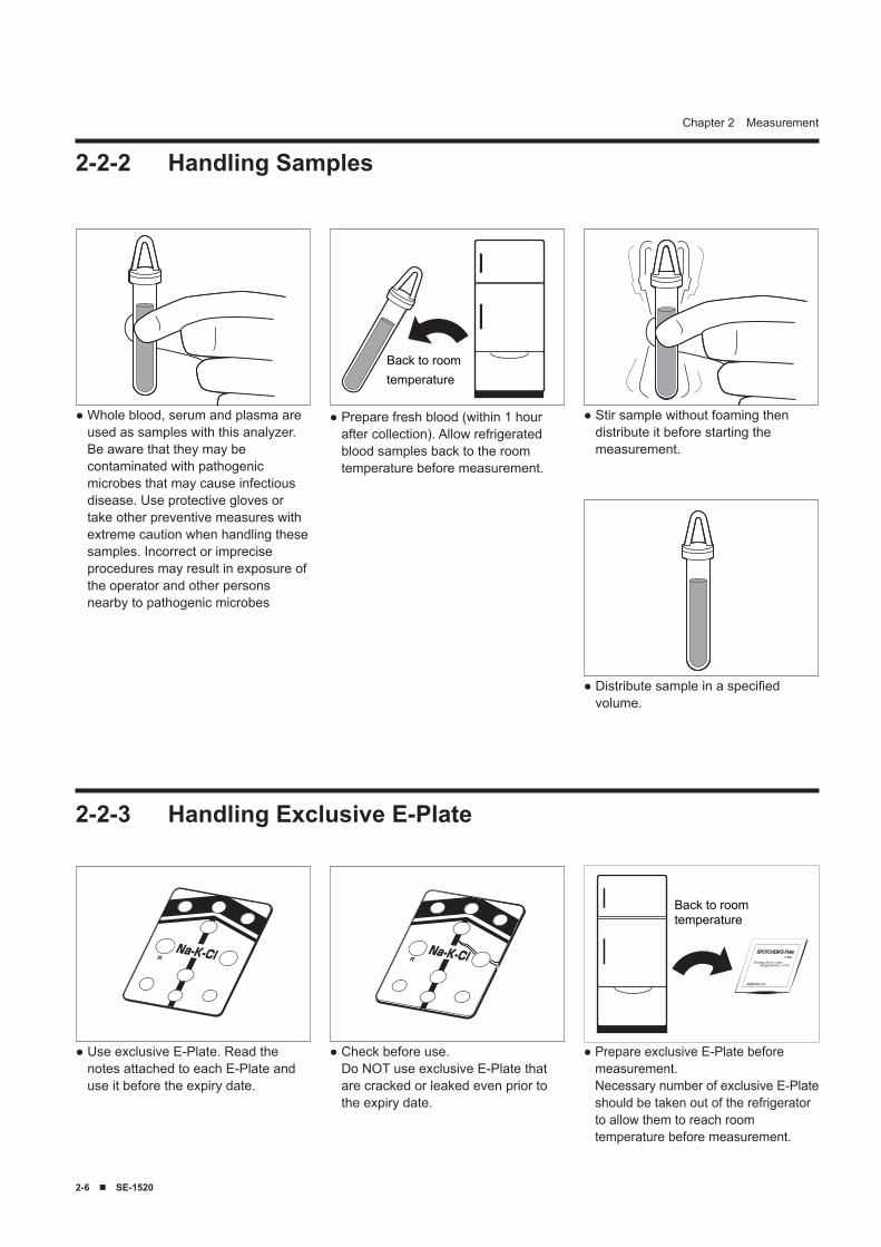
● Whole blood, serum and plasma are used as samples with this analyzer. Be aware that they may be contaminated with pathogenic microbes that may cause infectious disease. Use protective gloves or take other preventive measures with extreme caution when handling these samples. Incorrect or imprecise procedures may result in exposure of the operator and other persons nearby to pathogenic microbes
Back to roomtemperature
● Prepare fresh blood (within 1 hour after collection). Allow refrigerated blood samples back to the room temperature before measurement.
● Stir sample without foaming then distribute it before starting the measurement.
● Use exclusive E-Plate. Read the notes attached to each E-Plate and use it before the expiry date.
● Check before use. Do NOT use exclusive E-Plate that are cracked or leaked even prior to the expiry date.
Back to roomtemperature
● Prepare exclusive E-Plate before measurement. Necessary number of exclusive E-Plate should be taken out of the refrigerator to allow them to reach room temperature before measurement.
● Distribute sample in a specified volume.
SE-1520 ■ 2-7
Chapter 2 Measurement
2-2-4 Handling Magnetic Card
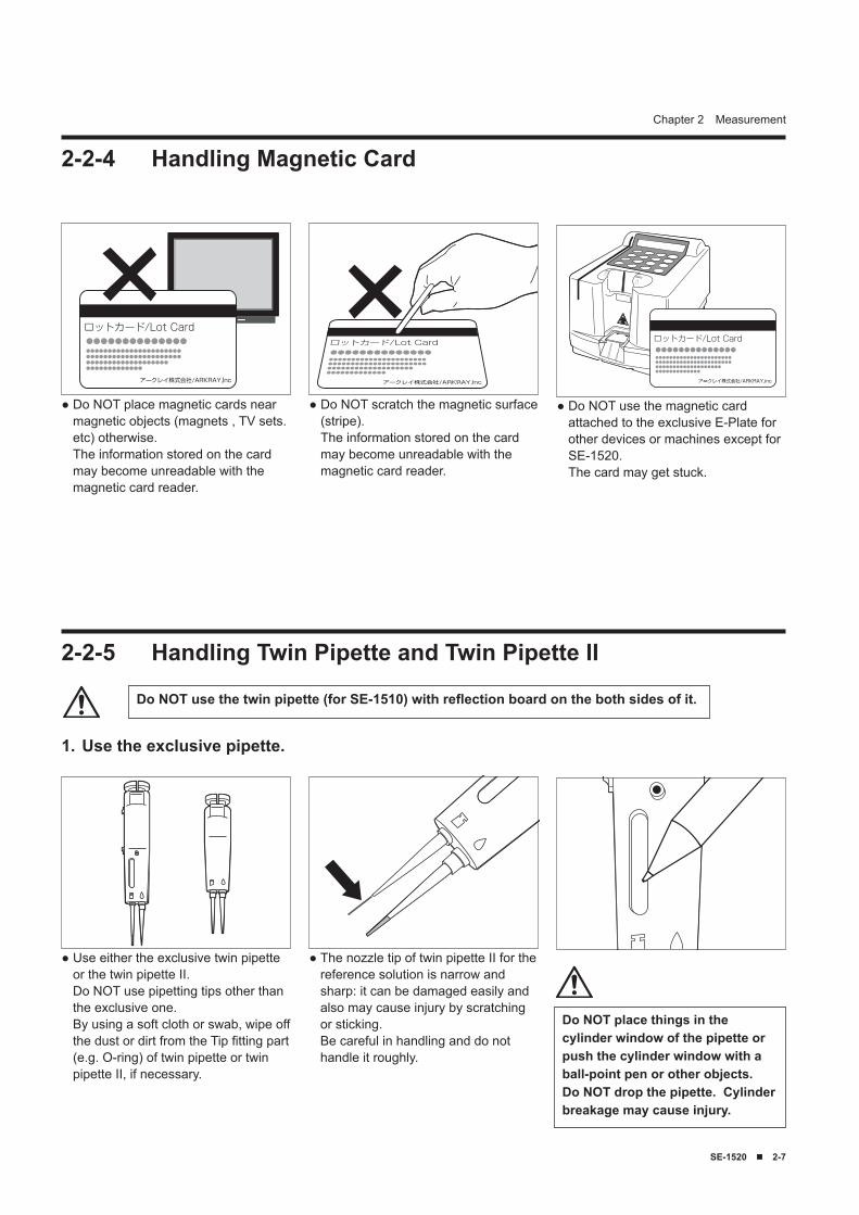
● Do NOT place magnetic cards near magnetic objects (magnets , TV sets. etc) otherwise. The information stored on the card may become unreadable with the magnetic card reader.
● Do NOT scratch the magnetic surface (stripe). The information stored on the card may become unreadable with the magnetic card reader.
● Do NOT use the magnetic card attached to the exclusive E-Plate for other devices or machines except for SE-1520. The card may get stuck.
Use the exclusive pipette.1.
2-2-5 Handling Twin Pipette and Twin Pipette II
● Use either the exclusive twin pipette or the twin pipette II. Do NOT use pipetting tips other than the exclusive one. By using a soft cloth or swab, wipe off the dust or dirt from the Tip fitting part (e.g. O-ring) of twin pipette or twin pipette II, if necessary.
● The nozzle tip of twin pipette II for the reference solution is narrow and sharp: it can be damaged easily and also may cause injury by scratching or sticking. Be careful in handling and do not handle it roughly.
Do NOT use the twin pipette (for SE-1510) with reflection board on the both sides of it.
Do NOT place things in the cylinder window of the pipette or push the cylinder window with a ball-point pen or other objects. Do NOT drop the pipette. Cylinder breakage may cause injury.
2-8 ■ SE-1520
Chapter 2 Measurement
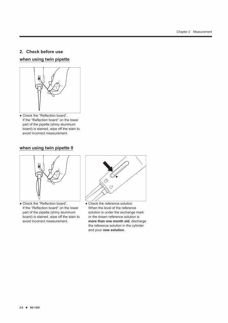
Check before use 2.
● Check the “Reflection board”. If the “Reflection board” on the lower part of the pipette (shiny aluminum board) is stained, wipe off the stain to avoid incorrect measurement.
● Check the “Reflection board”. If the “Reflection board” on the lower part of the pipette (shiny aluminum board) is stained, wipe off the stain to avoid incorrect measurement.
● Check the reference solution When the level of the reference solution is under the exchange mark or the drawn reference solution is more than one month old, discharge the reference solution in the cylinder and pour new solution.
when using twin pipette
when using twin pipette II
SE-1520 ■ 2-9
Chapter 2 Measurement
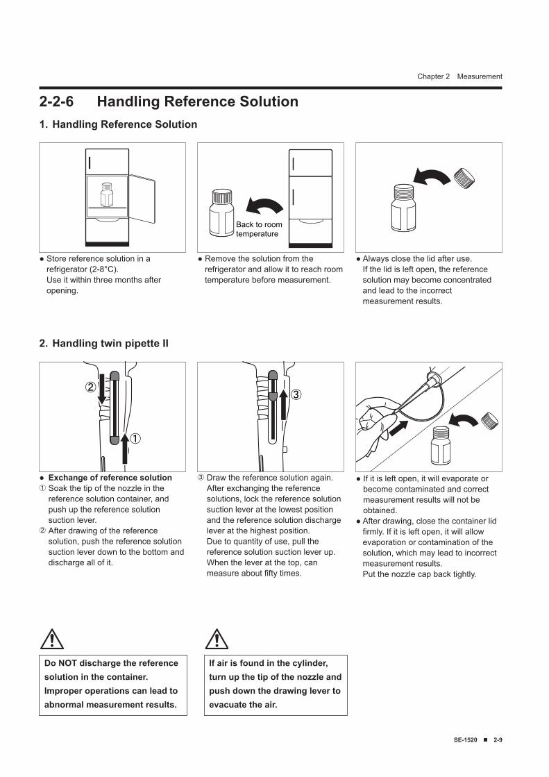
2-2-6 Handling Reference Solution
● Store reference solution in a refrigerator (2-8°C). Use it within three months after opening.
Back to roomtemperature
● Remove the solution from the refrigerator and allow it to reach room temperature before measurement.
● Always close the lid after use. If the lid is left open, the reference solution may become concentrated and lead to the incorrect measurement results.
If air is found in the cylinder, turn up the tip of the nozzle and push down the drawing lever to evacuate the air.
Do NOT discharge the reference solution in the container.Improper operations can lead to abnormal measurement results.
Handling Reference Solution1.
①
②
● Exchange of reference solution① Soak the tip of the nozzle in the
reference solution container, and push up the reference solution suction lever.
② After drawing of the reference solution, push the reference solution suction lever down to the bottom and discharge all of it.
③
③ Draw the reference solution again.After exchanging the reference solutions, lock the reference solution suction lever at the lowest position and the reference solution discharge lever at the highest position.Due to quantity of use, pull the reference solution suction lever up. When the lever at the top, can measure about fifty times.
● If it is left open, it will evaporate or become contaminated and correct measurement results will not be obtained.
● After drawing, close the container lid firmly. If it is left open, it will allow evaporation or contamination of the solution, which may lead to incorrect measurement results. Put the nozzle cap back tightly.
Handling twin pipette II2.
2-10 ■ SE-1520
Chapter 2 Measurement
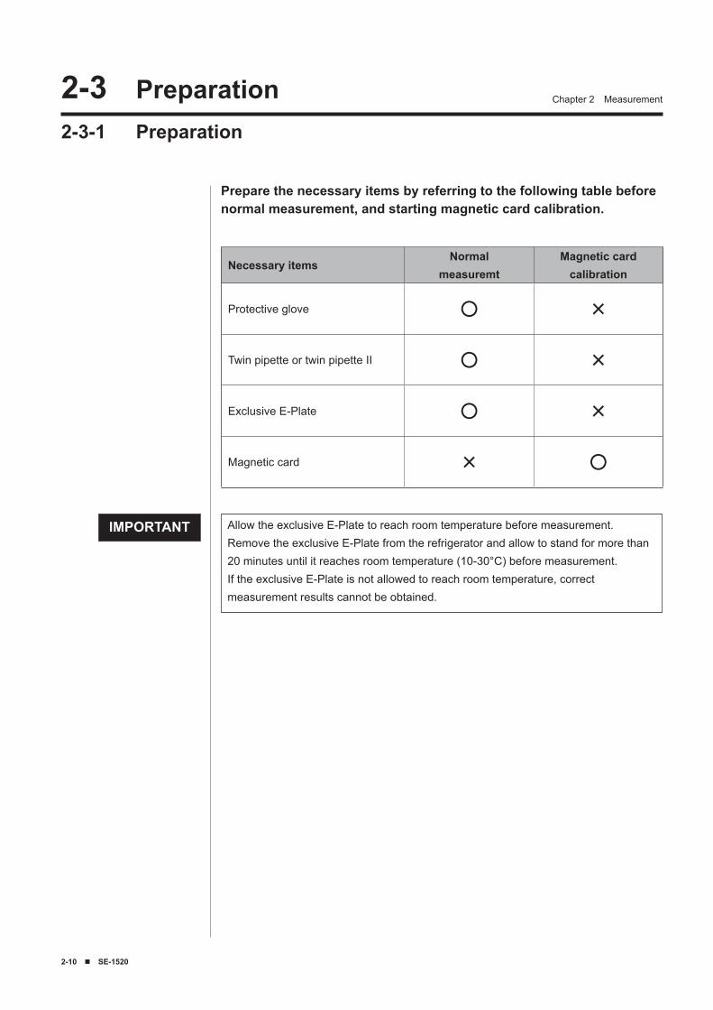
Prepare the necessary items by referring to the following table before normal measurement, and starting magnetic card calibration.
2-� Preparation2-3-1 Preparation
Allow the exclusive E-Plate to reach room temperature before measurement.Remove the exclusive E-Plate from the refrigerator and allow to stand for more than 20 minutes until it reaches room temperature (10-30°C) before measurement.If the exclusive E-Plate is not allowed to reach room temperature, correct measurement results cannot be obtained.
IMPORTANT
Necessary itemsNormal
measuremtMagnetic card
calibration
Protective glove ○ ×
Twin pipette or twin pipette II ○ ×
Exclusive E-Plate ○ ×
Magnetic card × ○
SE-1520 ■ 2-11
Chapter 2 Measurement
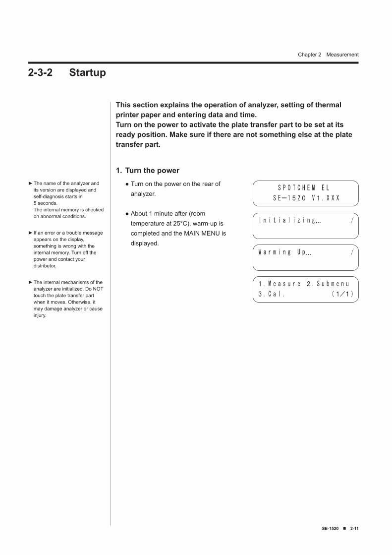
Turn the power1.Turn on the power on the rear of analyzer.
About 1 minute after (room temperature at 25°C), warm-up is completed and the MAIN MENU is displayed.
●
●
The name of the analyzer and its version are displayed and self-diagnosis starts in 5 seconds. The internal memory is checked on abnormal conditions.
If an error or a trouble message appears on the display, something is wrong with the internal memory. Turn off the power and contact your distributor.
The internal mechanisms of the analyzer are initialized. Do NOT touch the plate transfer part when it moves. Otherwise, it may damage analyzer or cause injury.
►
►
►
2-3-2 Startup
This section explains the operation of analyzer, setting of thermal printer paper and entering data and time.Turn on the power to activate the plate transfer part to be set at its ready position. Make sure if there are not something else at the plate transfer part.
S P O T C H E M E L
S Eー1520 V1. X X X
I n i t i a l i z i n g… /
W a r m i n g U p… /
1. M e a s u r e 2. S u b m e n u
3. C a l . (1/1)
2-12 ■ SE-1520
Chapter 2 Measurement
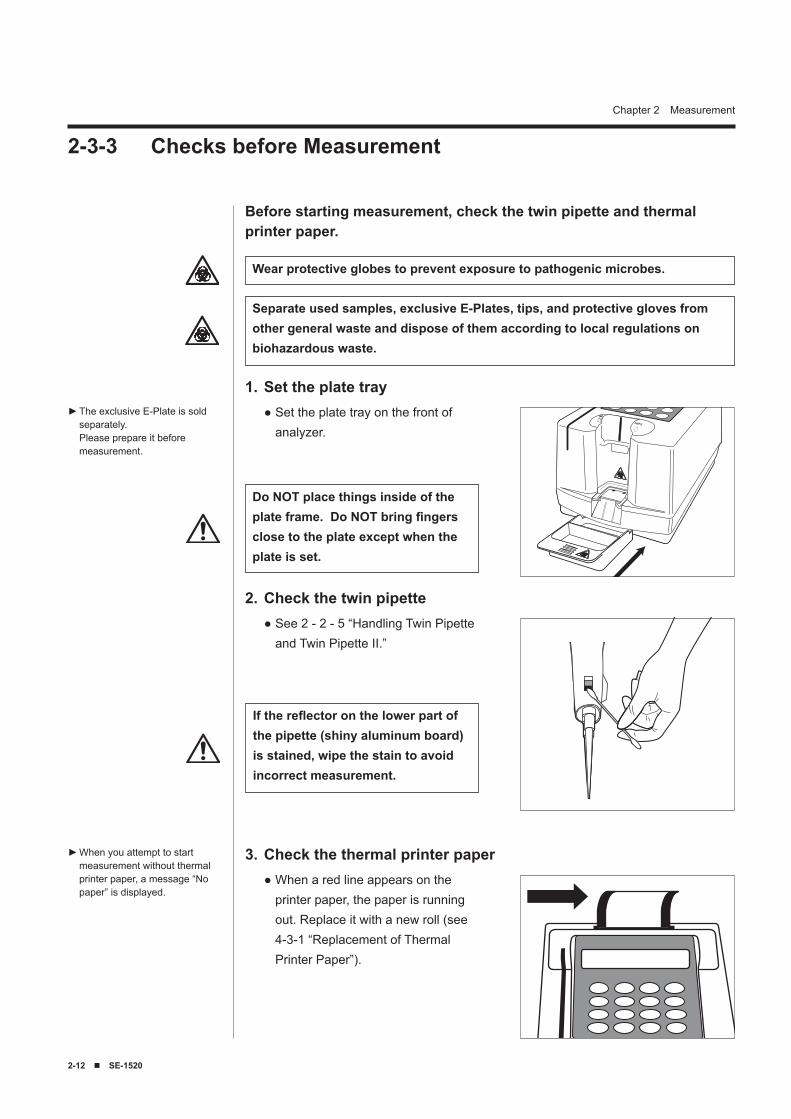
The exclusive E-Plate is sold separately. Please prepare it before measurement.
►
Wear protective globes to prevent exposure to pathogenic microbes.
Separate used samples, exclusive E-Plates, tips, and protective gloves from other general waste and dispose of them according to local regulations on biohazardous waste.
Set the plate tray1.Set the plate tray on the front of analyzer.
●
Check the twin pipette2.See 2 - 2 - 5 “Handling Twin Pipette and Twin Pipette II.”
●
Check the thermal printer paper3.When a red line appears on the printer paper, the paper is running out. Replace it with a new roll (see 4-3-1 “Replacement of Thermal Printer Paper”).
●
If the reflector on the lower part of the pipette (shiny aluminum board) is stained, wipe the stain to avoid incorrect measurement.
When you attempt to start measurement without thermal printer paper, a message “No paper” is displayed.
►
2-3-3 Checks before Measurement
Before starting measurement, check the twin pipette and thermal printer paper.
Do NOT place things inside of the plate frame. Do NOT bring fingers close to the plate except when the plate is set.
SE-1520 ■ 2-1�
Chapter 2 Measurement
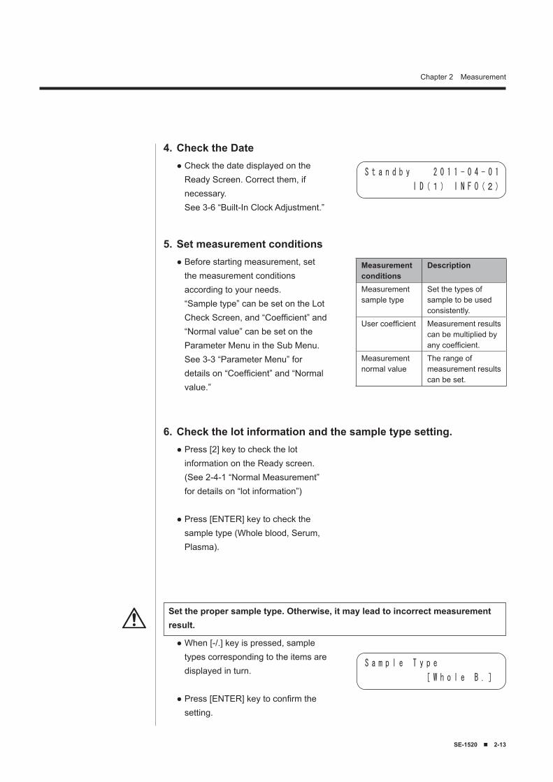
Set measurement conditions5.Before starting measurement, set the measurement conditions according to your needs. “Sample type” can be set on the Lot Check Screen, and “Coefficient” and “Normal value” can be set on the Parameter Menu in the Sub Menu. See 3-3 “Parameter Menu” for details on “Coefficient” and “Normal value.”
●
Check the Date4.Check the date displayed on the Ready Screen. Correct them, if necessary. See 3-6 “Built-In Clock Adjustment.”
●S t a n d b y 2 0 1 1 - 0 4 - 0 1
I D(1) I N F O(2)
Check the lot information and the sample type setting.6.Press [2] key to check the lot information on the Ready screen. (See 2-4-1 “Normal Measurement” for details on “lot information”)
Press [ENTER] key to check the sample type (Whole blood, Serum, Plasma).
●
●
When [-/.] key is pressed, sample types corresponding to the items are displayed in turn.
Press [ENTER] key to confirm the setting.
●
●
S a m p l e T y p e
[ W h o l e B . ]
Set the proper sample type. Otherwise, it may lead to incorrect measurement result.
Measurement conditions
Description
Measurement sample type
Set the types of sample to be used consistently.
User coefficient Measurement results can be multiplied by any coefficient.
Measurement normal value
The range of measurement results can be set.
2-1� ■ SE-1520
Chapter 2 Measurement
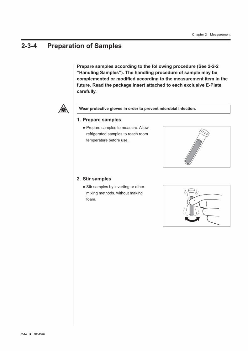
Prepare samples according to the following procedure (See 2-2-2“Handling Samples”). The handling procedure of sample may be complemented or modified according to the measurement item in the future. Read the package insert attached to each exclusive E-Plate carefully.
Prepare samples1.Prepare samples to measure. Allow refrigerated samples to reach room temperature before use.
●
Wear protective gloves in order to prevent microbial infection.
Stir samples2.Stir samples by inverting or other mixing methods. without making foam.
●
2-3-4 Preparation of Samples
SE-1520 ■ 2-15
Chapter 2 Measurement
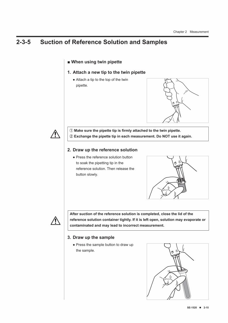
2-3-5 Suction of Reference Solution and Samples
① Make sure the pipette tip is firmly attached to the twin pipette.② Exchange the pipette tip in each measurement. Do NOT use it again.
Attach a new tip to the twin pipette1.Attach a tip to the top of the twin pipette.
●
■ When using twin pipette
Draw up the reference solution2.Press the reference solution button to soak the pipetting tip in the reference solution. Then release the button slowly.
●
After suction of the reference solution is completed, close the lid of the reference solution container tightly. If it is left open, solution may evaporate or contaminated and may lead to incorrect measurement.
Draw up the sample3.Press the sample button to draw up the sample.
●
2-1� ■ SE-1520
Chapter 2 Measurement
① Make sure that the pipetting tip is firmly attached to the twin pipette.② Exchange the pipetting tip for each measurement. Do NOT use it again.
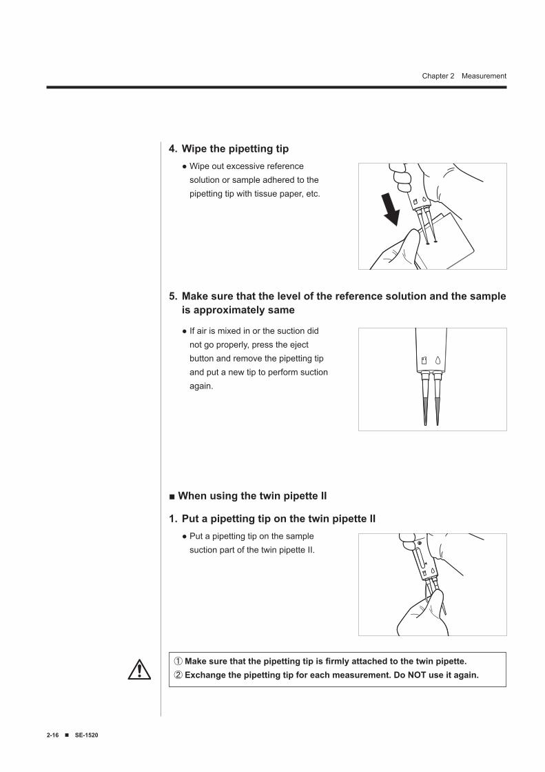
Wipe the pipetting tip4.Wipe out excessive reference solution or sample adhered to the pipetting tip with tissue paper, etc.
●
■ When using the twin pipette II
Make sure that the level of the reference solution and the sample is approximately same
5.
If air is mixed in or the suction did not go properly, press the eject button and remove the pipetting tip and put a new tip to perform suction again.
●
Put a pipetting tip on the twin pipette II1.Put a pipetting tip on the sample suction part of the twin pipette II.
●
SE-1520 ■ 2-17
Chapter 2 Measurement
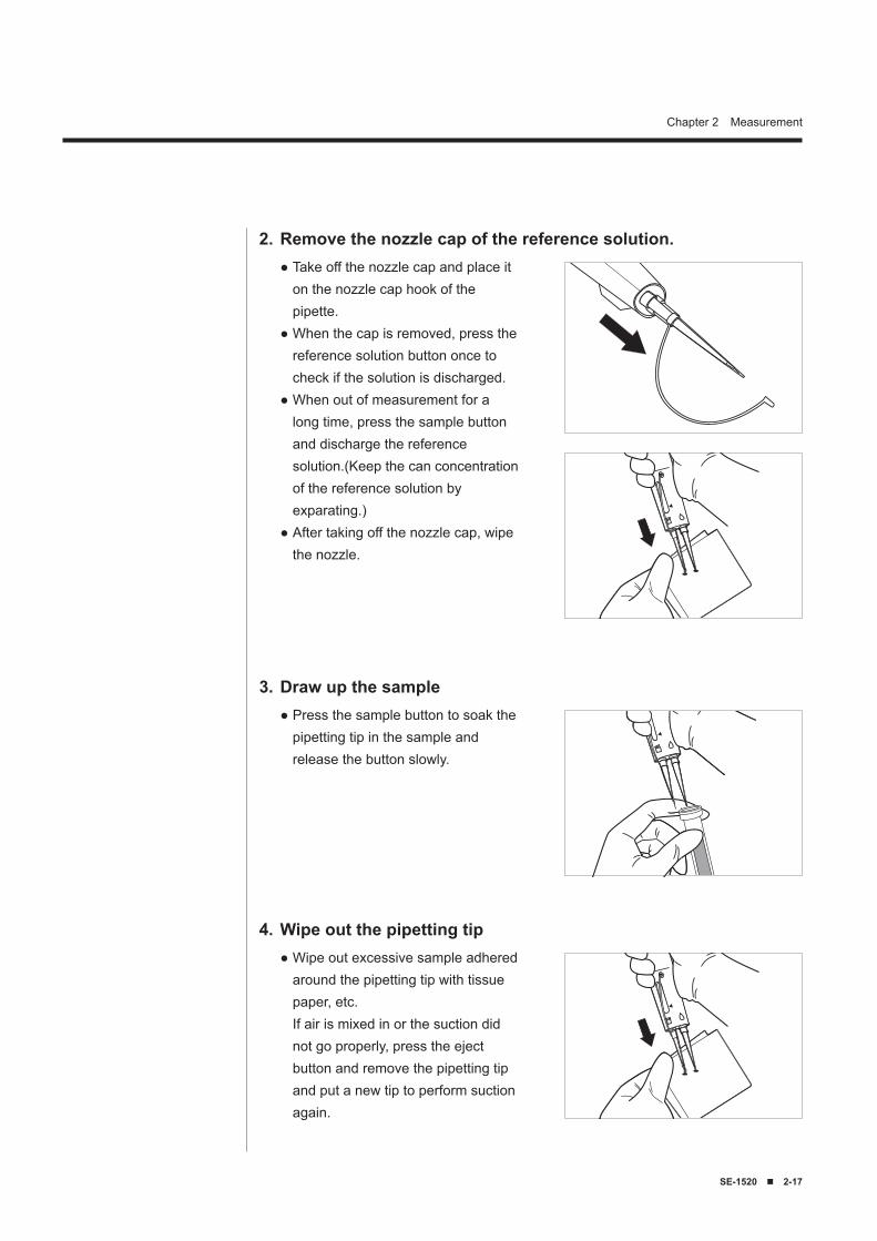
Remove the nozzle cap of the reference solution.2.Take off the nozzle cap and place it on the nozzle cap hook of the pipette.When the cap is removed, press the reference solution button once to check if the solution is discharged.When out of measurement for a long time, press the sample button and discharge the reference solution.(Keep the can concentration of the reference solution by exparating.)After taking off the nozzle cap, wipe the nozzle.
●
●
●
●
Draw up the sample3.Press the sample button to soak the pipetting tip in the sample and release the button slowly.
●
Wipe out the pipetting tip4.Wipe out excessive sample adhered around the pipetting tip with tissue paper, etc. If air is mixed in or the suction did not go properly, press the eject button and remove the pipetting tip and put a new tip to perform suction again.
●
2-18 ■ SE-1520
Chapter 2 Measurement
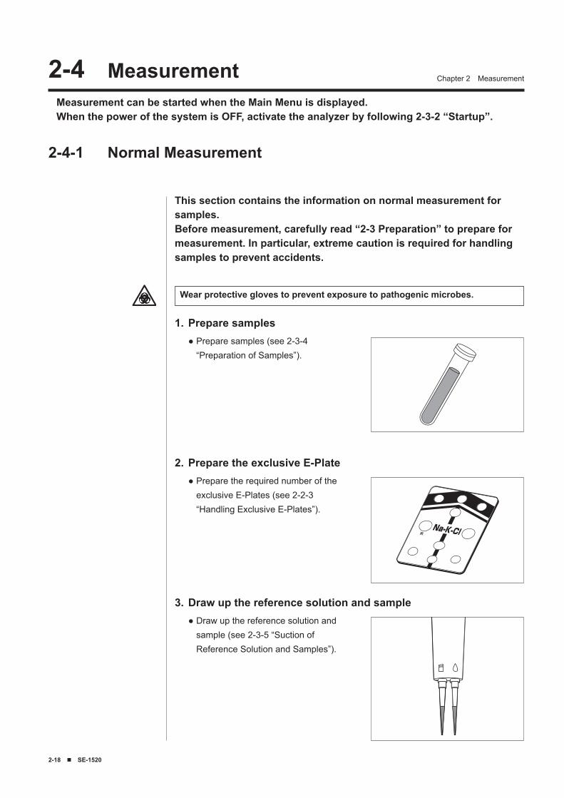
Prepare samples1.Prepare samples (see 2-3-4 “Preparation of Samples”).
●
Measurement can be started when the Main Menu is displayed.When the power of the system is OFF, activate the analyzer by following 2-3-2 “Startup”.
Prepare the exclusive E-Plate2.Prepare the required number of the exclusive E-Plates (see 2-2-3 “Handling Exclusive E-Plates”).
●
Draw up the reference solution and sample3.Draw up the reference solution and sample (see 2-3-5 “Suction of Reference Solution and Samples”).
●
2-4-1 Normal Measurement
2-� Measurement
This section contains the information on normal measurement for samples.Before measurement, carefully read “2-3 Preparation” to prepare for measurement. In particular, extreme caution is required for handling samples to prevent accidents.
Wear protective gloves to prevent exposure to pathogenic microbes.
SE-1520 ■ 2-19
Chapter 2 Measurement
Press the Start button4.
1
0
4
7 8 9
5 6
2 3
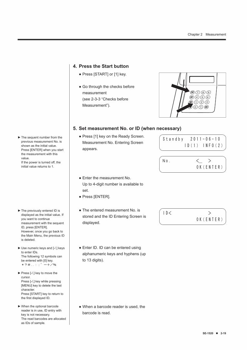
Press [START] or [1] key.
Go through the checks before measurement (see 2-3-3 “Checks before Measurement”).
●
●
Set measurement No. or ID (when necessary)5.Press [1] key on the Ready Screen. Measurement No. Entering Screen appears.
●
Enter the measurement No. Up to 4-digit number is available to set.Press [ENTER].
●
●
The sequent number from the previous measurement No. is shown as the initial value. Press [ENTER] when you start the measurement with this value. If the power is turned off, the initial value returns to 1.
► S t a n d b y 2 0 1 1 - 0 6 - 1 0
I D( 1 ) I N F O( 2 )
No . <_ >
O K( E N T E R )
The entered measurement No. is stored and the ID Entering Screen is displayed.
Enter ID. ID can be entered using alphanumeric keys and hyphens (up to 13 digits).
●
●
The previously entered ID is displayed as the initial value. If you want to continue measurement with the sequent ID, press [ENTER]. However, once you go back to the Main Menu, the previous ID is deleted.
Use numeric keys and [-/.] keys to enter IDs. The following 12 symbols can be entered with [0] key. *?# ..:;’ー+/%
Press [-/.] key to move the cursor. Press [-/.] key while pressing [MENU] key to delete the last character. Press [START] key to return to the first displayed ID.
When the optional barcode reader is in use, ID entry with key is not necessary. The read barcodes are allocated as IDs of sample.
►
►
►
►
I D< >
O K( E N T E R )
When a barcode reader is used, the barcode is read.
●
2-20 ■ SE-1520
Chapter 2 Measurement
Set the sample type (when necessary)6.See procedure 6 of 2-3-3 “Checks before Measurement” to set the sample type.
●
The entered ID is displayed.Press [ENTER].
The entered ID is stored and the screen returns to the Ready Screen.
●●
●
When the barcode reader is used, a message “Barcode reader is available” is displayed.
►
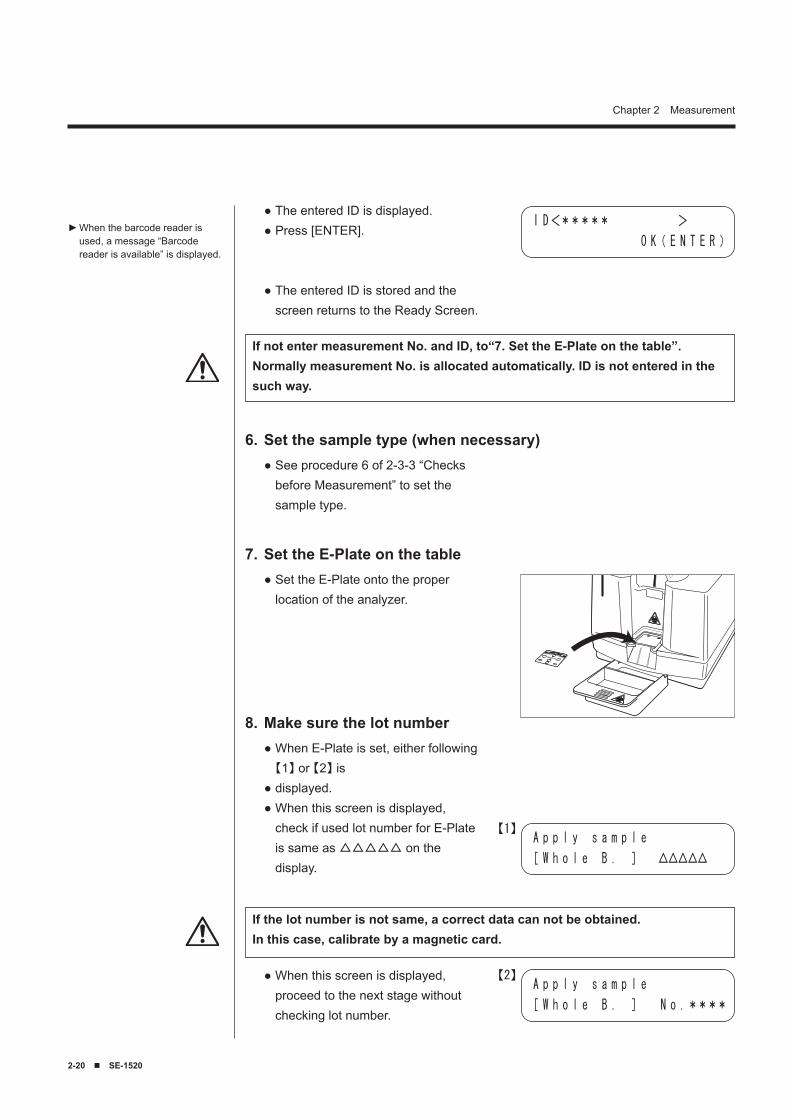
Set the E-Plate on the table7.Set the E-Plate onto the proper location of the analyzer.
●
Make sure the lot number8.When E-Plate is set, either following 【1】 or 【2】 isdisplayed.When this screen is displayed, check if used lot number for E-Plate is same as △△△△△ on the display.
●
●●
A p p l y s a m p l e
[ W h o l e B . ] △△△△△
When this screen is displayed, proceed to the next stage without checking lot number.
●A p p l y s a m p l e
[ W h o l e B . ] N o .****
If the lot number is not same, a correct data can not be obtained.In this case, calibrate by a magnetic card.
I D<***** >
O K( E N T E R )
If not enter measurement No. and ID, to“7. Set the E-Plate on the table”.Normally measurement No. is allocated automatically. ID is not entered in the such way.
【1】
【2】
SE-1520 ■ 2-21
Chapter 2 Measurement
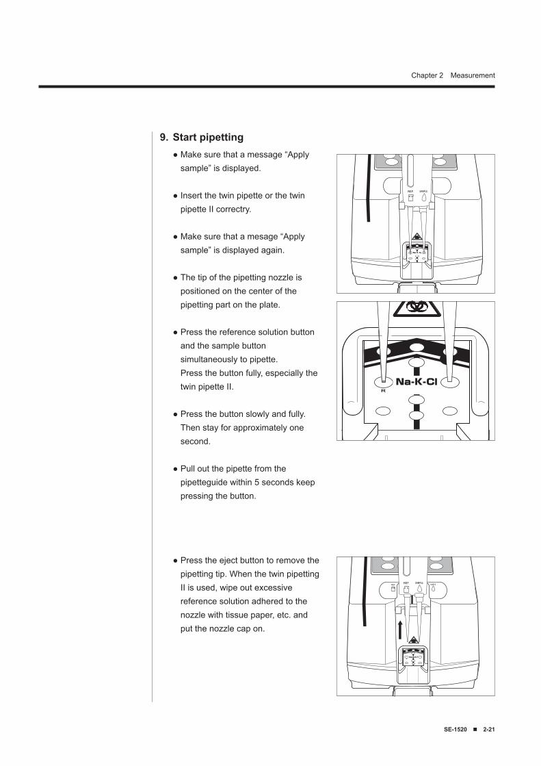
Start pipetting9.Make sure that a message “Apply sample” is displayed.
Insert the twin pipette or the twin pipette II correctry.
Make sure that a mesage “Apply sample” is displayed again.
The tip of the pipetting nozzle is positioned on the center of the pipetting part on the plate.
Press the reference solution button and the sample button simultaneously to pipette. Press the button fully, especially the twin pipette II.
Press the button slowly and fully. Then stay for approximately one second.
Pull out the pipette from the pipetteguide within 5 seconds keep pressing the button.
●
●
●
●
●
●
●
Press the eject button to remove the pipetting tip. When the twin pipetting II is used, wipe out excessive reference solution adhered to the nozzle with tissue paper, etc. and put the nozzle cap on.
●
REF. SAMPLE.
REF. SAMPLE.REF. SAMPLE.
REF. SAMPLE.
2-22 ■ SE-1520
Chapter 2 Measurement
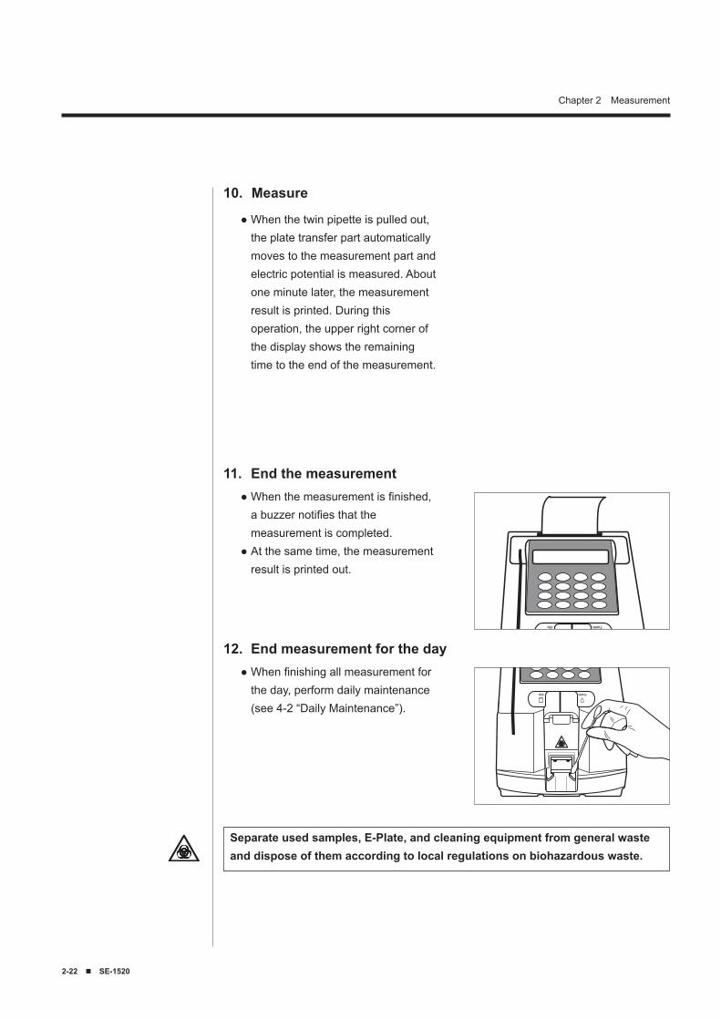
End the measurement11.When the measurement is finished, a buzzer notifies that the measurement is completed.At the same time, the measurement result is printed out.
●
●
Separate used samples, E-Plate, and cleaning equipment from general waste and dispose of them according to local regulations on biohazardous waste.
End measurement for the day12.When finishing all measurement for the day, perform daily maintenance (see 4-2 “Daily Maintenance”).
●
When the twin pipette is pulled out, the plate transfer part automatically moves to the measurement part and electric potential is measured. About one minute later, the measurement result is printed. During this operation, the upper right corner of the display shows the remaining time to the end of the measurement.
●
Measure10.
SE-1520 ■ 2-2�
Chapter 2 Measurement
2-5-1 Overview
2-5 Calibration
Calibration is necessary for maintaining measurement accuracy. By performing calibration, the problems caused by differences among lots are solved and measurement accuracy is maintained.Basically, calibration is performed for each exclusive plate type using exclusive calibrators. However, it will take a long time to perform calibration for all exclusive plates.To reduce the time and trouble, this system performs calibration by reading magnetic cards recording lot information of each exclusive plate.This method is called “Magnetic Card Calibration.”Using this magnetic card calibration method, calibration is performed by inserting the magnetic card attached to the exclusive plate into the magnetic card reader.
2-5-2 Magnetic Card CalibrationDifferences among lots of the exclusive plate are automatically corrected by inserting the magnetic card attached to the exclusive plate into the magnetic card reader.
If the measurement is performed when the magnetic card calibration is not performed correctly, errors occur and measurement may not start.In this case, be sure to perform “Magnetic Card Calibration.”
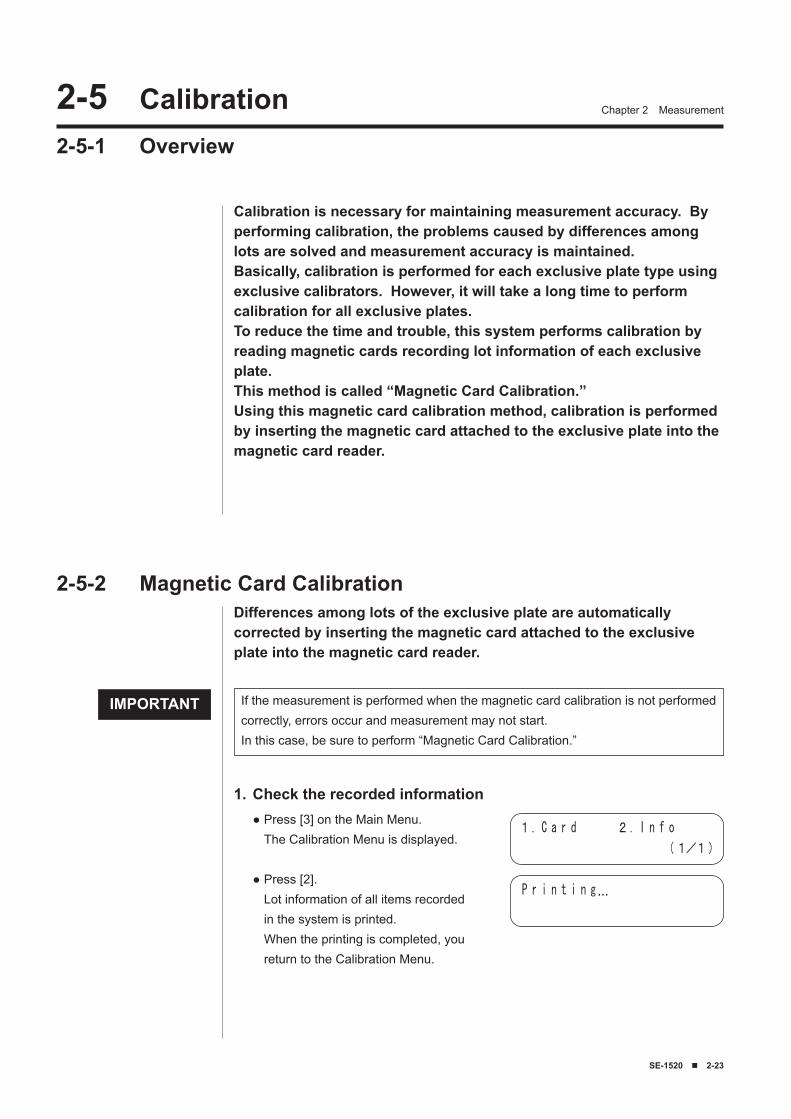
Check the recorded information1.Press [3] on the Main Menu. The Calibration Menu is displayed.
Press [2]. Lot information of all items recorded in the system is printed. When the printing is completed, you return to the Calibration Menu.
●
●
1. C a r d 2. I n f o
(1/1)
P r i n t i n g…
IMPORTANT
2-2� ■ SE-1520
Chapter 2 Measurement
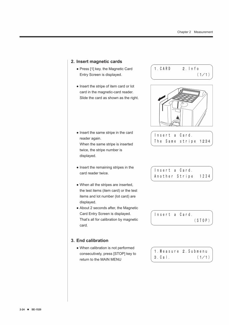
Insert magnetic cards2.Press [1] key. the Magnetic Card Entry Screen is displayed.
Insert the stripe of item card or lot card in the magnetic-card reader. Slide the card as shown as the right.
Insert the same stripe in the card reader again. When the same stripe is inserted twice, the stripe number is displayed.
Insert the remaining stripes in the card reader twice.
When all the stripes are inserted, the test items (item card) or the test items and lot number (lot card) are displayed.About 2 seconds after, the Magnetic Card Entry Screen is displayed. That’s all for calibration by magnetic card.
●
●
●
●
●
●
End calibration3.When calibration is not performed consecutively, press [STOP] key to return to the MAIN MENU
●
1. C A R D 2. I n f o
(1/1)
I n s e r t a C a r d .
T h e S a m e s t r i p e 1234
I n s e r t a C a r d .
( S T O P )
I n s e r t a C a r d .
A n o t h e r S t r i p e 1 2 3 4
1. M e a s u r e 2. S u b m e n u
3. C a l . (1/1)
SE-1520 ■ 2-25
Chapter 2 Measurement2-� Measurement Result2-6-1 Printing the Normal Measurement Results
(1) Normal printing
126
3
4
5
7
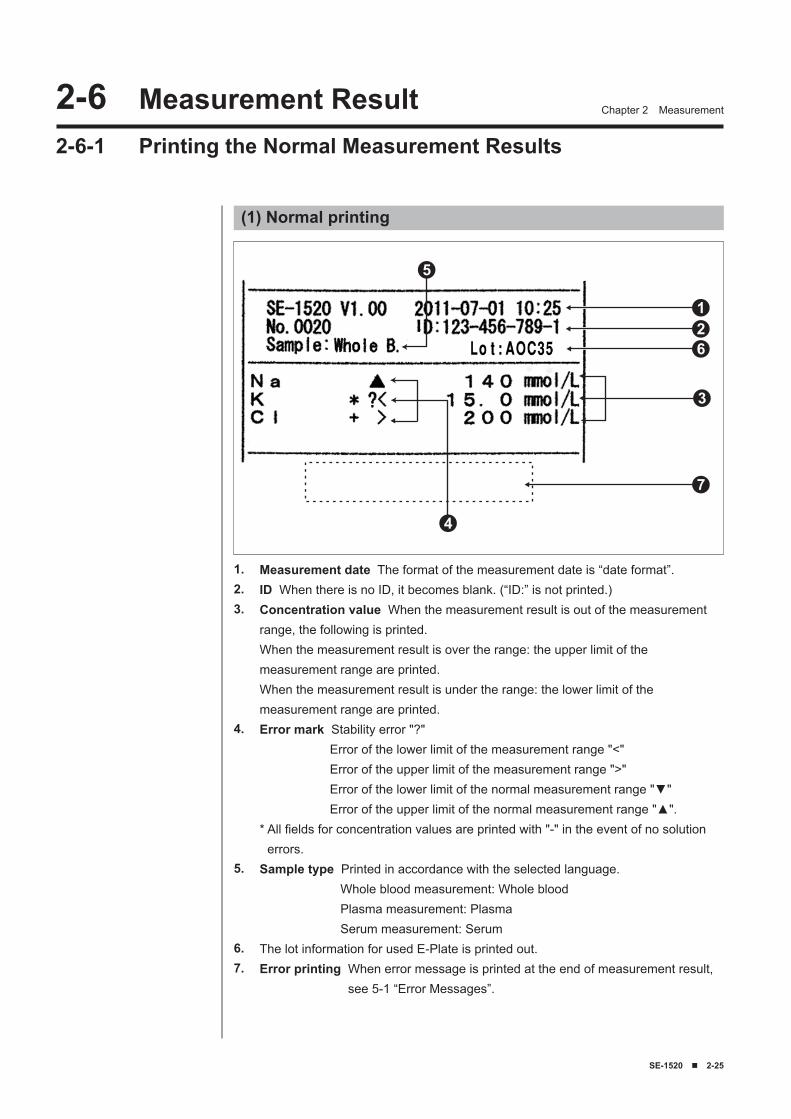
Measurement date The format of the measurement date is “date format”.ID When there is no ID, it becomes blank. (“ID:” is not printed.)Concentration value When the measurement result is out of the measurement range, the following is printed.When the measurement result is over the range: the upper limit of the measurement range are printed.When the measurement result is under the range: the lower limit of the measurement range are printed.Error mark Stability error "?" Error of the lower limit of the measurement range "<" Error of the upper limit of the measurement range ">" Error of the lower limit of the normal measurement range "▼" Error of the upper limit of the normal measurement range "▲".* All fields for concentration values are printed with "-" in the event of no solution
errors.Sample type Printed in accordance with the selected language. Whole blood measurement: Whole blood Plasma measurement: Plasma Serum measurement: SerumThe lot information for used E-Plate is printed out.Error printing When error message is printed at the end of measurement result,
see 5-1 “Error Messages”.
1.2.3.
4.
5.
6.7.
2-2� ■ SE-1520
Chapter 2 Measurement
(2) Survey mode printing
123
4
5
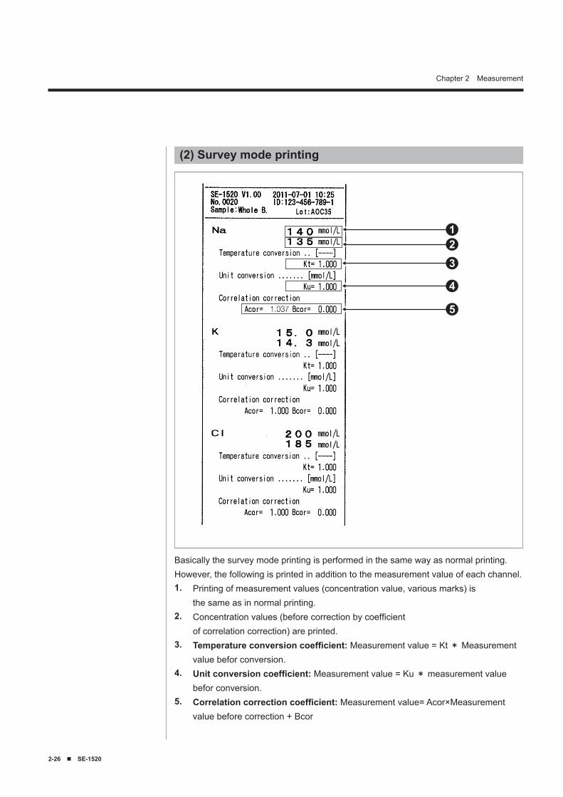
Basically the survey mode printing is performed in the same way as normal printing. However, the following is printed in addition to the measurement value of each channel.
Printing of measurement values (concentration value, various marks) isthe same as in normal printing.Concentration values (before correction by coefficientof correlation correction) are printed.Temperature conversion coefficient: Measurement value = Kt * Measurement value befor conversion.Unit conversion coefficient: Measurement value = Ku * measurement value befor conversion.Correlation correction coefficient: Measurement value= Acor×Measurement value before correction + Bcor
1.
2.
3.
4.
5.
SE-1520 ■ �-1
The SE-1520 has a main menu and five sub menus.Sub menus are classified by setting items.Chapter 3 explains how to perform Sub Menu settings.
Chapter 3
Sub Menu
3-1 Overview3-1-1 Contents of Each Menu
3-2 Measurement Results Menu3-2-1 Printing Measurement Results3-2-2 Transmitting Measurement Results3-2-3 Deleting Measurement Results3-2-4 Wildcards
3-3 Parameter Menu3-3-1 Printing Parameters3-3-2 Entering Parameters3-3-3 Initializing Parameters
3-4 Maintenance Menu3-4-1 Cleaning the Probe3-4-2 Cleaning the Table3-4-3 Check Measurement
�-5 Mode Menu3-5-1 Survey Mode
3-6 Built-in Clock Adjustment
�-2 ■ SE-1520
Chapter 3 Sub Menu�-1 Overview3-1-1 Contents of Each Menu
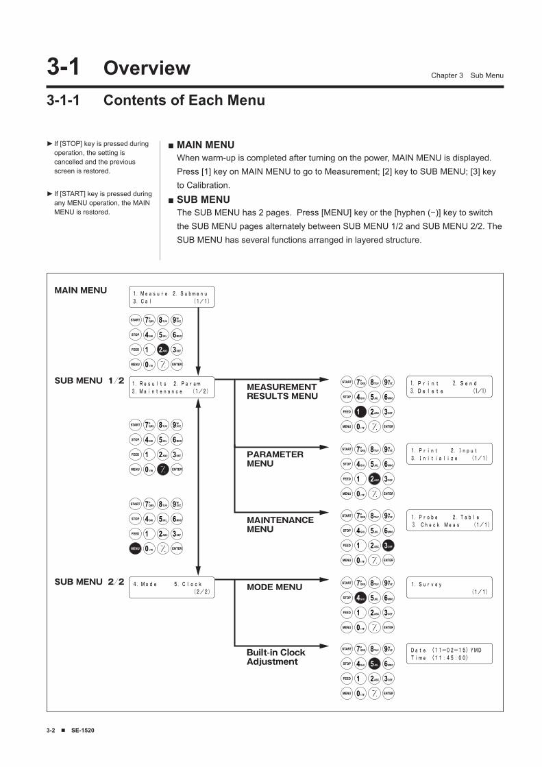
■ MAIN MENUWhen warm-up is completed after turning on the power, MAIN MENU is displayed. Press [1] key on MAIN MENU to go to Measurement; [2] key to SUB MENU; [3] key to Calibration.
■ SUB MENUThe SUB MENU has 2 pages. Press [MENU] key or the [hyphen (−)] key to switch the SUB MENU pages alternately between SUB MENU 1/2 and SUB MENU 2/2. The SUB MENU has several functions arranged in layered structure.
If [STOP] key is pressed during operation, the setting is cancelled and the previous screen is restored.
If [START] key is pressed during any MENU operation, the MAIN MENU is restored.
►
►
1.Measure 2.Submenu3.Cal (1/1)
START 7PQRS 8TUV 9W
XYZ
STOP 4GHI 5JKL 6MNO
FEED
ENTER
1 2ABC 3DEF
MENU 0 ?#-
.
1.Results 2.Param3.Maintenance (1/2)
START 7PQRS 8TUV 9W
XYZ
STOP 4GHI 5JKL 6MNO
FEED
ENTER
1 2ABC 3DEF
MENU 0 ?#-
.
START 7PQRS 8TUV 9W
XYZ
STOP 4GHI 5JKL 6MNO
FEED
ENTER
1 2ABC 3DEF
MENU 0 ?#-
.
4.Mode 5.Clock (2/2)
START 7PQRS 8TUV 9W
XYZ
STOP 4GHI 5JKL 6MNO
FEED
ENTER
1 2ABC 3DEF
MENU 0 ?#-
.
1. Print 2. Send3. Delete (1/1)
START 7PQRS 8TUV 9W
XYZ
STOP 4GHI 5JKL 6MNO
FEED
ENTER
1 2ABC 3DEF
MENU 0 ?#-
.
1.Print 2.Input3.Initialize (1/1)
START 7PQRS 8TUV 9W
XYZ
STOP 4GHI 5JKL 6MNO
FEED
ENTER
1 2ABC 3DEF
MENU 0 ?#-
.
1.Probe 2.Table 3. Check Meas (1/1)
START 7PQRS 8TUV 9W
XYZ
STOP 4GHI 5JKL 6MNO
FEED
ENTER
1 2ABC 3DEF
MENU 0 ?#-
.
1.Survey (1/1)
START 7PQRS 8TUV 9W
XYZ
STOP 4GHI 5JKL 6MNO
FEED
ENTER
1 2ABC 3DEF
MENU 0 ?#-
.
Date 〈11ー02ー15〉YMDTime 〈11:45:00〉
SE-1520 ■ �-�
Chapter 3 Sub Menu
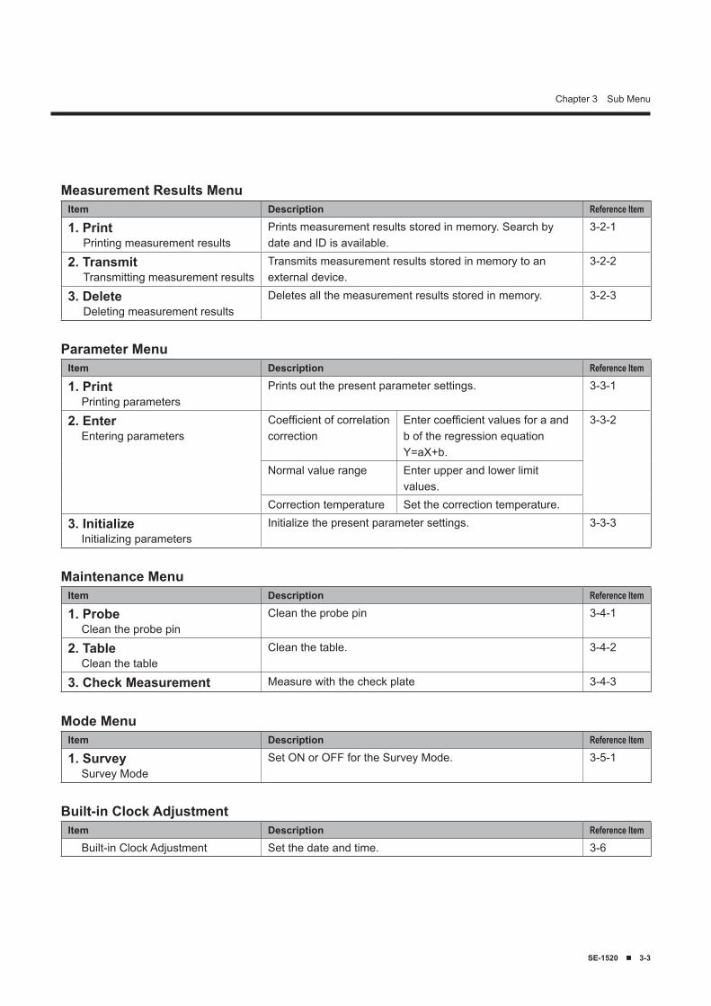
Measurement Results MenuItem Description Reference Item
1. PrintPrinting measurement results
Prints measurement results stored in memory. Search by date and ID is available.
3-2-1
2. TransmitTransmitting measurement results
Transmits measurement results stored in memory to an external device.
3-2-2
3. DeleteDeleting measurement results
Deletes all the measurement results stored in memory. 3-2-3
Parameter MenuItem Description Reference Item
1. PrintPrinting parameters
Prints out the present parameter settings. 3-3-1
2. EnterEntering parameters
Coefficient of correlation correction
Enter coefficient values for a and b of the regression equation Y=aX+b.
3-3-2
Normal value range Enter upper and lower limit values.
Correction temperature Set the correction temperature.
3. InitializeInitializing parameters
Initialize the present parameter settings. 3-3-3
Maintenance MenuItem Description Reference Item
1. ProbeClean the probe pin
Clean the probe pin 3-4-1
2. TableClean the table
Clean the table. 3-4-2
3. Check Measurement Measure with the check plate 3-4-3
Mode MenuItem Description Reference Item
1. SurveySurvey Mode
Set ON or OFF for the Survey Mode. 3-5-1
Built-in Clock AdjustmentItem Description Reference Item
Built-in Clock Adjustment Set the date and time. 3-6
�-� ■ SE-1520
Chapter 3 Sub Menu�-2 Measurement Results Menu3-2-1 Printing Measurement Results
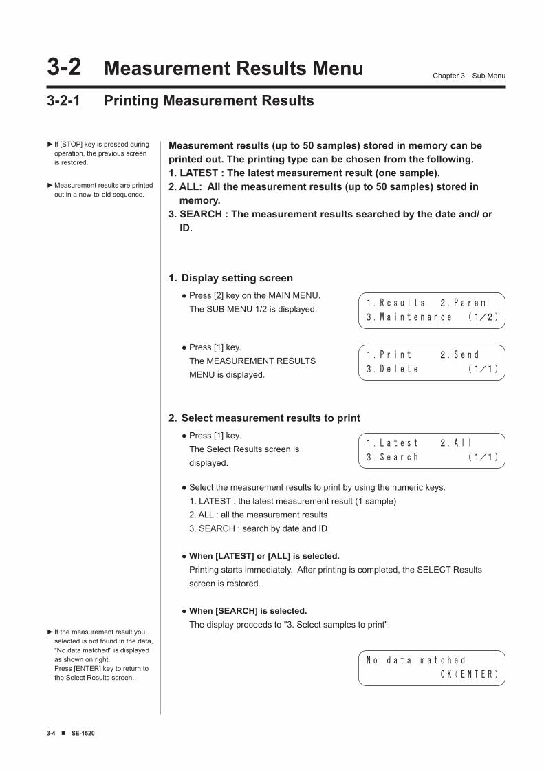
Measurement results (up to 50 samples) stored in memory can be printed out. The printing type can be chosen from the following.1. LATEST : The latest measurement result (one sample).2. ALL: All the measurement results (up to 50 samples) stored in
memory.3. SEARCH : The measurement results searched by the date and/ or
ID.
If [STOP] key is pressed during operation, the previous screen is restored.
Measurement results are printed out in a new-to-old sequence.
►
►
Display setting screen1.Press [2] key on the MAIN MENU. The SUB MENU 1/2 is displayed.
●
Press [1] key. The MEASUREMENT RESULTS MENU is displayed.
●
Select measurement results to print2.Press [1] key. The Select Results screen is displayed.
●
Select the measurement results to print by using the numeric keys. 1. LATEST : the latest measurement result (1 sample) 2. ALL : all the measurement results 3. SEARCH : search by date and ID
When [LATEST] or [ALL] is selected. Printing starts immediately. After printing is completed, the SELECT Results screen is restored.
When [SEARCH] is selected. The display proceeds to "3. Select samples to print".
●
●
●
If the measurement result you selected is not found in the data, "No data matched" is displayed as shown on right. Press [ENTER] key to return to the Select Results screen.
►
1. R e s u l t s 2. P a r a m
3. M a i n t e n a n c e (1/2)
1. P r i n t 2. S e n d
3. D e l e t e (1/1)
1. L a t e s t 2. A l l
3. S e a r c h (1/1)
N o d a t a m a t c h e d
O K( E N T E R )
SE-1520 ■ �-5
Chapter 3 Sub Menu
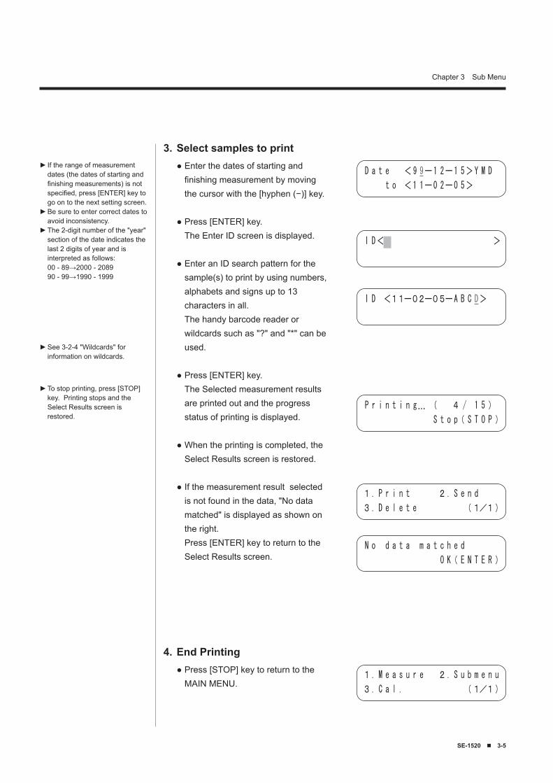
If the range of measurement dates (the dates of starting and finishing measurements) is not specified, press [ENTER] key to go on to the next setting screen.Be sure to enter correct dates to avoid inconsistency.The 2-digit number of the "year" section of the date indicates the last 2 digits of year and is interpreted as follows: 00 - 89→2000 - 2089 90 - 99→1990 - 1999
►
►
►
Select samples to print3.Enter the dates of starting and finishing measurement by moving the cursor with the [hyphen (−)] key.
Press [ENTER] key. The Enter ID screen is displayed.
Enter an ID search pattern for the sample(s) to print by using numbers, alphabets and signs up to 13 characters in all. The handy barcode reader or wildcards such as "?" and "*" can be used.
Press [ENTER] key. The Selected measurement results are printed out and the progress status of printing is displayed.
When the printing is completed, the Select Results screen is restored.
If the measurement result selected is not found in the data, "No data matched" is displayed as shown on the right. Press [ENTER] key to return to the Select Results screen.
●
●
●
●
●
●
To stop printing, press [STOP] key. Printing stops and the Select Results screen is restored.
►
End Printing4.Press [STOP] key to return to the MAIN MENU.
●
See 3-2-4 "Wildcards" for information on wildcards.
►
D a t e < 9 9ー1 2ー1 5> Y M D
t o <1 1ー0 2ー0 5>
I D< >
I D <11ー02ー05ーA B C D>
P r i n t i n g… ( 4 / 1 5 )
S t o p( S T O P )
1. P r i n t 2. S e n d
3. D e l e t e (1/1)
N o d a t a m a t c h e d
O K( E N T E R )
1. M e a s u r e 2. S u b m e n u
3. C a l . (1/1)
�-� ■ SE-1520
Chapter 3 Sub Menu
3-2-2 Transmitting Measurement Results
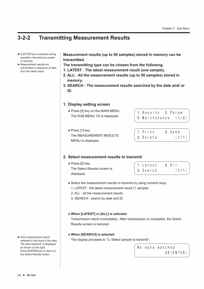
Measurement results (up to 50 samples) stored in memory can be transmitted.The transmitting type can be chosen from the following.1. LATEST : The latest measurement result (one sample).2. ALL: All the measurement results (up to 50 samples) stored in
memory.3. SEARCH : The measurement results searched by the date and/ or
ID.
If [STOP] key is pressed during operation, the previous screen is restored.Measurement results are transmitted in sequence of date from the latest result.
►
►
Display setting screen1.Press [2] key on the MAIN MENU. The SUB MENU 1/2 is displayed.
●
Press [1] key. The MEASUREMENT RESULTS MENU is displayed.
●
Select measurement results to transmit2.Press [2] key. The Select Results screen is displayed.
●
Select the measurement results to transmit by using numeric keys. 1. LATEST : the latest measurement result (1 sample) 2. ALL : all the measurement results 3. SEARCH : search by date and ID
When [LATEST] or [ALL] is selected Transmission starts immediately. After transmission is completed, the Select Results screen is restored.
When [SEARCH] is selected The display proceeds to "3. Select sample to transmit".
●
●
●If the measurement result selected is not found in the data, "No data matched" is displayed as shown on the right. Press [ENTER] key to return to the Select Results screen.
►
1. R e s u l t s 2. P a r a m
3. M a i n t e n a n c e (1/2)
1. P r i n t 2. S e n d
3. D e l e t e (1/1)
1. L a t e s t 2. A l l
3. S e a r c h (1/1)
N o d a t a m a t c h e d
O K( E N T E R )
SE-1520 ■ �-7
Chapter 3 Sub Menu
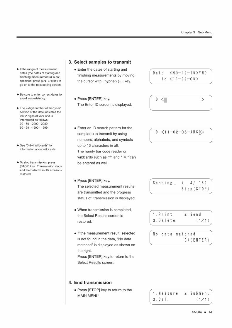
If the range of measurement dates (the dates of starting and finishing measurements) is not specified, press [ENTER] key to go on to the next setting screen.
Be sure to enter correct dates to avoid inconsistency.
The 2-digit number of the "year" section of the date indicates the last 2 digits of year and is interpreted as follows: 00 - 89→2000 - 2089 90 - 99→1990 - 1999
►
►
►
Select samples to transmit3.Enter the dates of starting and finishing measurements by moving the cursor with [hyphen (−)] key.
Press [ENTER] key. The Enter ID screen is displayed.
Enter an ID search pattern for the sample(s) to transmit by using numbers, alphabets, and symbols up to 13 characters in all. The handy bar code reader or wildcards such as "?" and " * " can be entered as well.
Press [ENTER] key. The selected measurement results are transmitted and the progress status of transmission is displayed.
When transmission is completed, the Select Results screen is restored.
If the measurement result selected is not found in the data, "No data matched" is displayed as shown on the right. Press [ENTER] key to return to the Select Results screen.
●
●
●
●
●
●
To stop transmission, press [STOP] key. Transmission stops and the Select Results screen is restored.
►
End transmission4.Press [STOP] key to return to the MAIN MENU.
●
See "3-2-4 Wildcards" for information about wildcards.
►
D a t e <99ー12ー1 5> Y M D
t o <1 1ー0 2ー05>
I D < >
I D <11ー02ー05ーA B C D>
S e n d i n g… ( 4/ 1 5 )
S t o p( S T O P )
1. P r i n t 2. S e n d
3. D e l e t e (1/1)
N o d a t a m a t c h e d
O K( E N T E R )
1. M e a s u r e 2. S u b m e n u
3. C a l . (1/1)
�-8 ■ SE-1520
Chapter 3 Sub Menu
3-2-3 Deleting Measurement Results
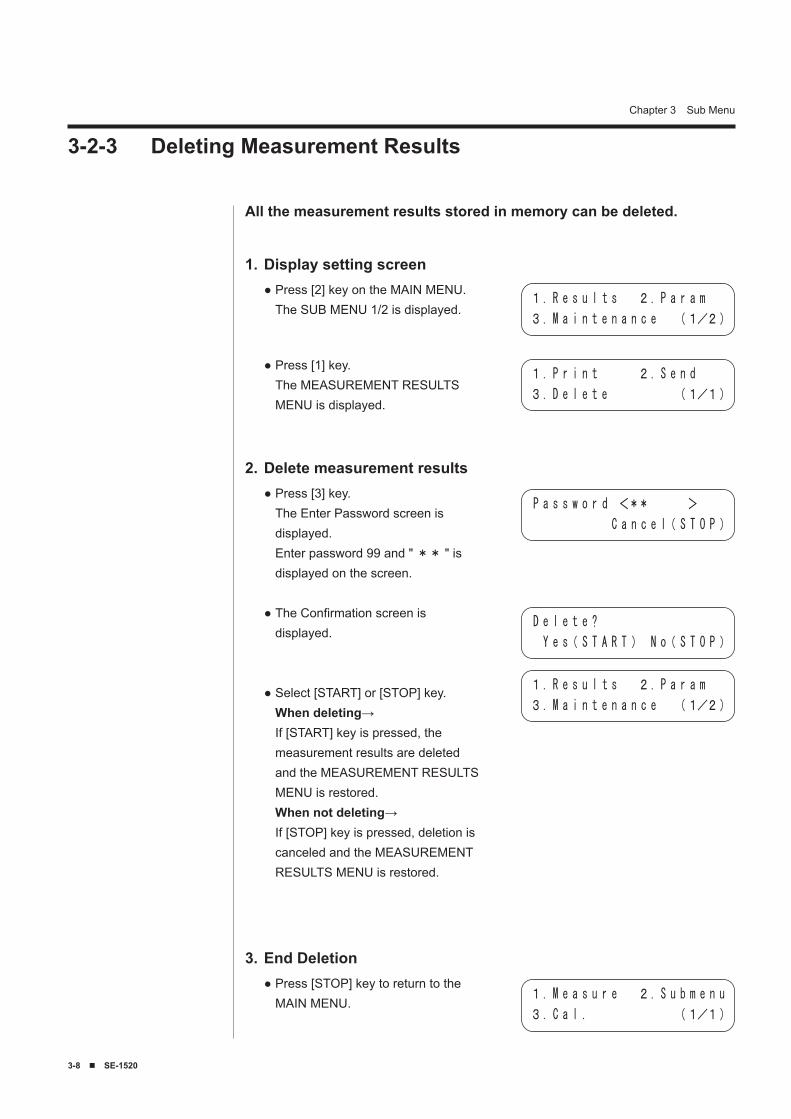
All the measurement results stored in memory can be deleted.
Display setting screen1.Press [2] key on the MAIN MENU. The SUB MENU 1/2 is displayed.
●
Press [1] key. The MEASUREMENT RESULTS MENU is displayed.
●
Delete measurement results2.Press [3] key. The Enter Password screen is displayed. Enter password 99 and " ** " is displayed on the screen.
The Confirmation screen is displayed.
Select [START] or [STOP] key. When deleting→ If [START] key is pressed, the measurement results are deleted and the MEASUREMENT RESULTS MENU is restored. When not deleting→ If [STOP] key is pressed, deletion is canceled and the MEASUREMENT RESULTS MENU is restored.
●
●
●
End Deletion3.Press [STOP] key to return to the MAIN MENU.
●
1. R e s u l t s 2. P a r a m
3. M a i n t e n a n c e (1/2)
1. P r i n t 2. S e n d
3. D e l e t e (1/1)
P a s s w o r d <** >
C a n c e l( S T O P )
D e l e t e ?
Y e s( S T A R T ) N o( S T O P )
1. R e s u l t s 2. P a r a m
3. M a i n t e n a n c e (1/2)
1. M e a s u r e 2. S u b m e n u
3. C a l . (1/1)
SE-1520 ■ �-9
Chapter 3 Sub Menu
3-2-4 Wildcards
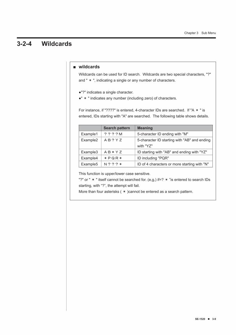
wildcards■Wildcards can be used for ID search. Wildcards are two special characters, "?" and " * ", indicating a single or any number of characters.
●"?" indicates a single character.●" * " indicates any number (including zero) of characters.
For instance, if "????" is entered, 4-character IDs are searched. If "A * " is entered, IDs starting with "A" are searched. The following table shows details.
This function is upper/lower case sensitive."?" or " * " itself cannot be searched for. (e,g,) if=? * ”is entered to search IDs starting, with “?”, the attempt will fail.More than four asterisks ( * )cannot be entered as a search pattern.
Search pattern MeaningExample1 ????M 5-character ID ending with "M"Example2 AB?YZ 5-character ID starting with "AB" and ending
with "YZ"Example3 AB*YZ ID starting with "AB" and ending with "YZ"Example4 *PQR* ID including "PQR"Example5 N???* ID of 4 characters or more starting with "N"
�-10 ■ SE-1520
Chapter 3 Sub Menu
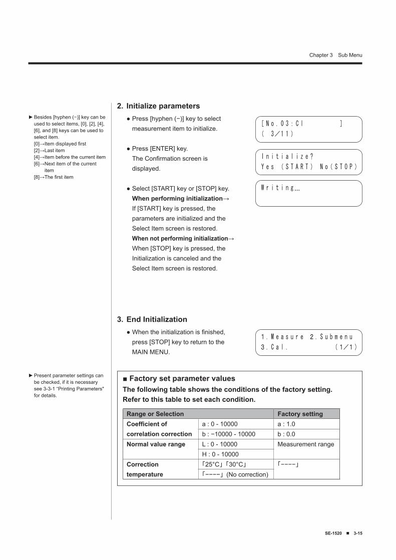
Besides [hyphen (−)] key, [0], [2], [4], [6], and [8] keys can be used in selecting items.[0]→Item displayed first[2]→Last item[4]→Item before the current item[6]→ Next item of the current
item[8]→The first item
When [ALL] is selected, the parameter settings of all the items are printed.
To stop printing, press [STOP] key. Printing stops and the Select Item screen is restored.
►
►
►
�-� Parameter Menu3-3-1 Printing Parameters
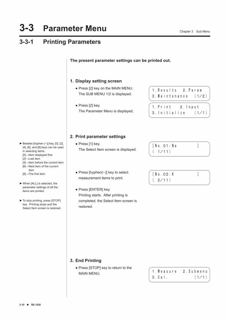
The present parameter settings can be printed out.
Display setting screen1.Press [2] key on the MAIN MENU. The SUB MENU 1/2 is displayed.
Press [2] key. The Parameter Menu is displayed.
●
●
Print parameter settings2.Press [1] key. The Select Item screen is displayed.
Press [hyphen(−)] key to select measurement items to print.
Press [ENTER] key. Printing starts. After printing is completed, the Select Item screen is restored.
●
●
●
End Printing3.Press [STOP] key to return to the MAIN MENU.
●
1. R e s u l t s 2. P a r a m
3. M a i n t e n a n c e (1/2)
1. P r i n t 2. I n p u t
3. I n i t i a l i z e (1/1)
[ N o .01:N a ]
( 1/11)
[ N o .02:K ]
( 2/11)
1. M e a s u r e 2. S u b m e n u
3. C a l . (1/1)
SE-1520 ■ �-11
Chapter 3 Sub Menu
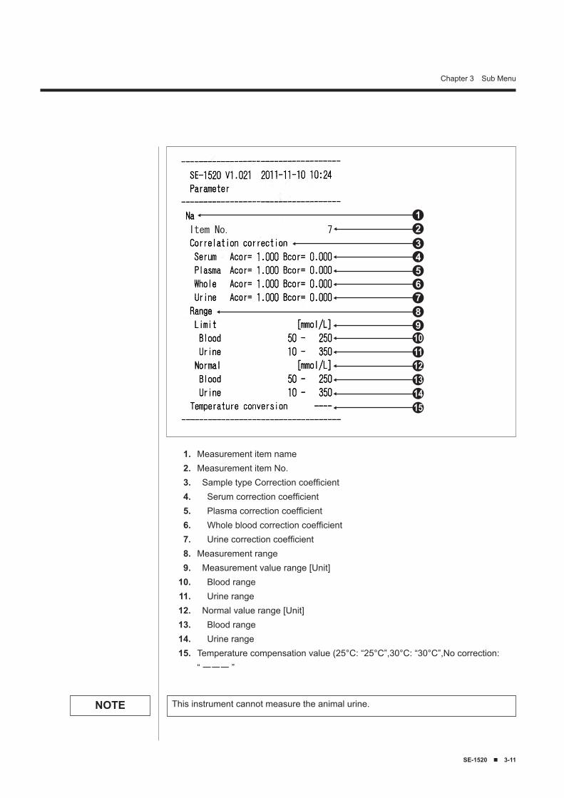
Item No. 7
123456789101112131415
Measurement item nameMeasurement item No. Sample type Correction coefficient Serum correction coefficient Plasma correction coefficient Whole blood correction coefficient Urine correction coefficientMeasurement range Measurement value range [Unit] Blood range Urine range Normal value range [Unit] Blood range Urine rangeTemperature compensation value (25°C: “25°C”,30°C: “30°C”,No correction:“ ーーー ”
1.2.3.4.5.6.7.8.9.
10.11.12.13.14.15.
This instrument cannot measure the animal urine.NOTE
�-12 ■ SE-1520
Chapter 3 Sub Menu
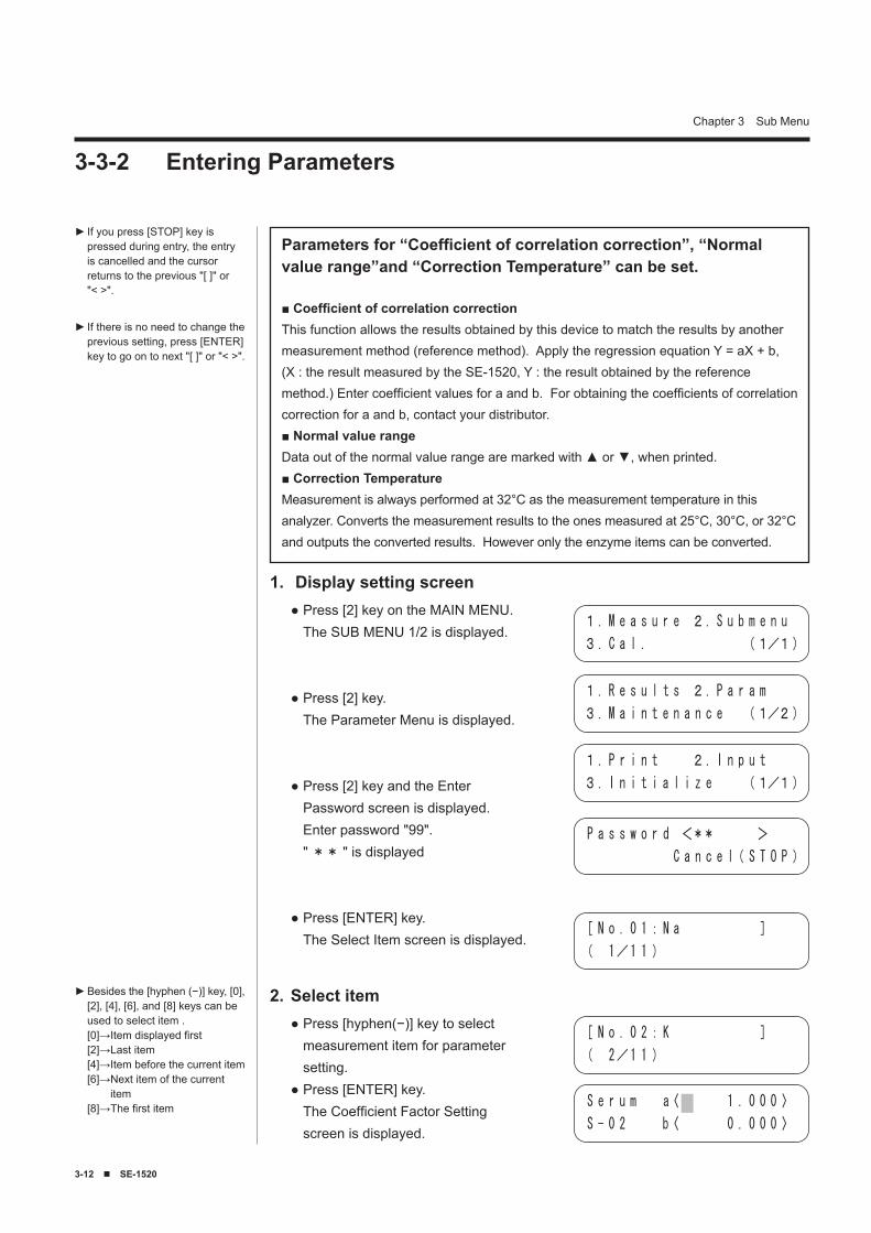
3-3-2 Entering Parameters
If you press [STOP] key is pressed during entry, the entry is cancelled and the cursor returns to the previous "[ ]" or "< >".
If there is no need to change the previous setting, press [ENTER] key to go on to next "[ ]" or "< >".
►
►
Parameters for “Coefficient of correlation correction”, “Normal value range”and “Correction Temperature” can be set.
■ Coefficient of correlation correctionThis function allows the results obtained by this device to match the results by another measurement method (reference method). Apply the regression equation Y = aX + b, (X : the result measured by the SE-1520, Y : the result obtained by the reference method.) Enter coefficient values for a and b. For obtaining the coefficients of correlation correction for a and b, contact your distributor.■ Normal value rangeData out of the normal value range are marked with ▲ or ▼, when printed.■ Correction Temperature Measurement is always performed at 32°C as the measurement temperature in this analyzer. Converts the measurement results to the ones measured at 25°C, 30°C, or 32°C and outputs the converted results. However only the enzyme items can be converted.
Display setting screen1.Press [2] key on the MAIN MENU. The SUB MENU 1/2 is displayed.
Press [2] key. The Parameter Menu is displayed.
Press [2] key and the Enter Password screen is displayed. Enter password "99". " ** " is displayed
Press [ENTER] key. The Select Item screen is displayed.
●
●
●
●[ N o . 0 1: N a ]
( 1/1 1 )
Select item2.Press [hyphen(−)] key to select measurement item for parameter setting.Press [ENTER] key. The Coefficient Factor Setting screen is displayed.
●
●
[ N o . 0 2: K ]
( 2/1 1 )
S e r u m a〈 1 . 0 0 0 〉
S - 0 2 b〈 0 . 0 0 0 〉
Besides the [hyphen (−)] key, [0], [2], [4], [6], and [8] keys can be used to select item .[0]→Item displayed first[2]→Last item[4]→Item before the current item[6]→ Next item of the current
item[8]→The first item
►
1. R e s u l t s 2. P a r a m
3. M a i n t e n a n c e (1/2)
1. M e a s u r e 2. S u b m e n u
3. C a l . (1/1)
1. P r i n t 2. I n p u t
3. I n i t i a l i z e (1/1)
P a s s w o r d <** >
C a n c e l( S T O P )
SE-1520 ■ �-1�
Chapter 3 Sub Menu
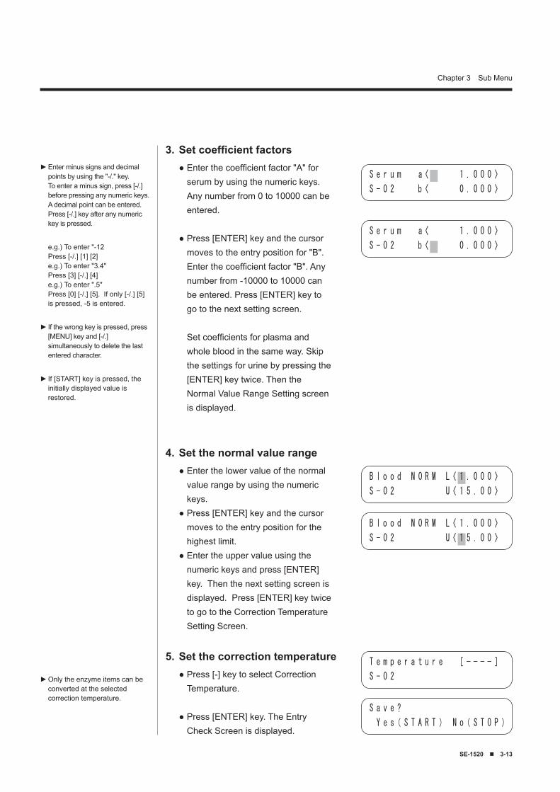
Set the normal value range4.Enter the lower value of the normal value range by using the numeric keys.Press [ENTER] key and the cursor moves to the entry position for the highest limit.Enter the upper value using the numeric keys and press [ENTER] key. Then the next setting screen is displayed. Press [ENTER] key twice to go to the Correction Temperature Setting Screen.
●
●
●
Set coefficient factors3.Enter the coefficient factor "A" for serum by using the numeric keys. Any number from 0 to 10000 can be entered.
Press [ENTER] key and the cursor moves to the entry position for "B". Enter the coefficient factor "B". Any number from -10000 to 10000 can be entered. Press [ENTER] key to go to the next setting screen. Set coefficients for plasma and whole blood in the same way. Skip the settings for urine by pressing the [ENTER] key twice. Then the Normal Value Range Setting screen is displayed.
●
●
Enter minus signs and decimal points by using the "-/." key. To enter a minus sign, press [-/.] before pressing any numeric keys. A decimal point can be entered. Press [-/.] key after any numeric key is pressed.
e.g.) To enter "-12Press [-/.] [1] [2]e.g.) To enter "3.4"Press [3] [-/.] [4]e.g.) To enter ".5"Press [0] [-/.] [5]. If only [-/.] [5] is pressed, -5 is entered.
If the wrong key is pressed, press [MENU] key and [-/.] simultaneously to delete the last entered character.
If [START] key is pressed, the initially displayed value is restored.
►
►
►
B l o o d N O R M L〈 1 . 0 0 0 〉
S - 0 2 U〈 1 5 . 0 0 〉
S a v e ?
Y e s( S T A R T ) N o( S T O P )
S e r u m a〈 1 . 0 0 0 〉
S - 0 2 b〈 0 . 0 0 0 〉
S e r u m a〈 1 . 0 0 0 〉
S - 0 2 b〈 0 . 0 0 0 〉
Set the correction temperature5.Press [-] key to select Correction Temperature.
Press [ENTER] key. The Entry Check Screen is displayed.
●
●
T e m p e r a t u r e [ − − − − ]
S - 0 2
B l o o d N O R M L〈 1 . 0 0 0 〉
S - 0 2 U〈 1 5 . 0 0 〉
Only the enzyme items can be converted at the selected correction temperature.
►
�-1� ■ SE-1520
Chapter 3 Sub Menu
3-3-3 Initializing Parameters
Parameter settings can be initialized to the factory setting. See "Factory set parameter values" for the details.
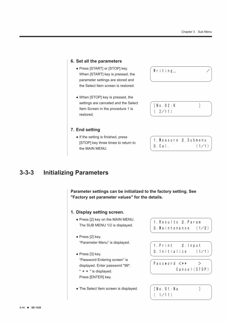
Display setting screen.1.Press [2] key on the MAIN MENU. The SUB MENU 1/2 is displayed.
Press [2] key. “Parameter Menu” is displayed.
Press [3] key. “Password Entering screen” is displayed. Enter password "99". " ** " is displayed. Press [ENTER] key.
The Select Item screen is displayed.
●
●
●
●
Set all the parameters6.Press [START] or [STOP] key. When [START] key is pressed, the parameter settings are stored and the Select Item screen is restored.
When [STOP] key is pressed, the settings are canceled and the Select Item Screen in the procedure 1 is restored.
●
●
End setting7.If the setting is finished, press [STOP] key three times to return to the MAIN MENU.
●
W r i t i n g… /
[ N o . 0 2: K ]
( 2/1 1 )
[ N o . 0 1: N a ]
( 1/1 1 )
1. R e s u l t s 2. P a r a m
3. M a i n t e n a n c e (1/2)
1. P r i n t 2. I n p u t
3. I n i t i a l i z e (1/1)
P a s s w o r d <** >
C a n c e l( S T O P )
1. M e a s u r e 2. S u b m e n u
3. C a l . (1/1)
SE-1520 ■ �-15
Chapter 3 Sub Menu
Initialize parameters2.Press [hyphen (−)] key to select measurement item to initialize.
Press [ENTER] key. The Confirmation screen is displayed.
Select [START] key or [STOP] key. When performing initialization→ If [START] key is pressed, the parameters are initialized and the Select Item screen is restored. When not performing initialization→ When [STOP] key is pressed, the Initialization is canceled and the Select Item screen is restored.
●
●
●
End Initialization3.When the initialization is finished, press [STOP] key to return to the MAIN MENU.
●
The following table shows the conditions of the factory setting.Refer to this table to set each condition.
Present parameter settings can be checked, if it is necessary see 3-3-1 “Printing Parameters" for details.
► ■ Factory set parameter values
Besides [hyphen (−)] key can be used to select items, [0], [2], [4], [6], and [8] keys can be used to select item.[0]→Item displayed first[2]→Last item[4]→Item before the current item[6]→ Next item of the current
item[8]→The first item
►[ N o . 0 3: C l ]
( 3/1 1 )
W r i t i n g…
I n i t i a l i z e ?
Y e s ( S T A R T ) N o( S T O P )
1. M e a s u r e 2. S u b m e n u
3. C a l . (1/1)
Range or Selection Factory settingCoefficient of correlation correction
a : 0 - 10000 a : 1.0b : −10000 - 10000 b : 0.0
Normal value range L : 0 - 10000 Measurement rangeH : 0 - 10000
Correction temperature
「25°C」「30°C」 「−−−−」「−−−−」(No correction)
�-1� ■ SE-1520
Chapter 3 Sub Menu�-� Maintenance Menu3-4-1 Cleaning the Probe
When [1. Probe] is selected, the block inside the analyzer moves. Open the maintenance cover of the bottom to clean the probe pin. See "4-3-2 Cleaning the Probe" for the details.
●
3-4-2 Cleaning the Table
When [2. Table] is selected, the plate transfer part is drawn back inside the system. When the plate transfer part is drawn back, the plate setting place and table of the system can be cleaned. See "4-2-2 Cleaning the Plate Transfer Part" for the details.
●
3-4-3 Check Measurement
When [3. Check Meas] is selected, check measurements with check plates can be performed. See "4-3-2 Cleaning the Probe" for the details.
●
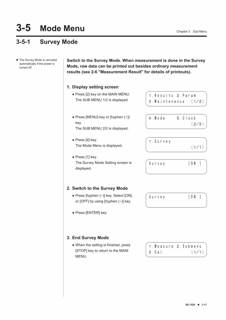
SE-1520 ■ �-17
Chapter 3 Sub Menu�-5 Mode Menu3-5-1 Survey Mode
Switch to the Survey Mode. When measurement is done in the Survey Mode, raw data can be printed out besides ordinary measurement results (see 2-6 "Measurement Result" for details of printouts).
Display setting screen1.Press [2] key on the MAIN MENU. The SUB MENU 1/2 is displayed.
Press [MENU] key or [hyphen (−)] key. The SUB MENU 2/2 is displayed.
Press [4] key. The Mode Menu is displayed.
Press [1] key. The Survey Mode Setting screen is displayed.
●
●
●
●
Switch to the Survey Mode2.Press [hyphen (−)] key. Select [ON] or [OFF] by using [hyphen (−)] key.
Press [ENTER] key.
●
●
The Survey Mode is canceled automatically if the power is turned off.
►
End Survey Mode3.When the setting is finished, press [STOP] key to return to the MAIN MENU.
●
1. R e s u l t s 2. P a r a m
3. M a i n t e n a n c e (1/2)
4. M o d e 5. C l o c k
(2/2)
1. S u r v e y
(1/1)
S u r v e y [ O N ]
1. M e a s u r e 2. S u b m e n u
3. C a l . (1/1)
S u r v e y [ O N ]
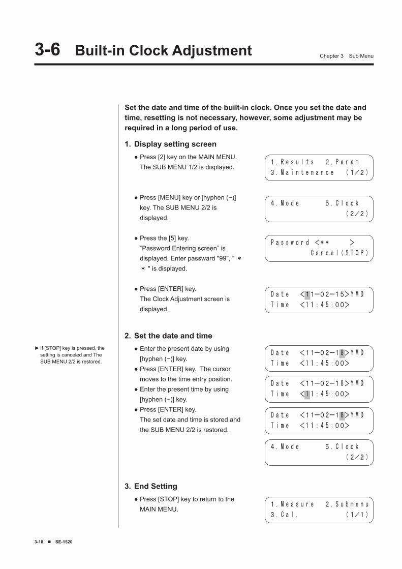
�-18 ■ SE-1520
Chapter 3 Sub Menu�-� Built-in Clock Adjustment
Set the date and time of the built-in clock. Once you set the date and time, resetting is not necessary, however, some adjustment may be required in a long period of use.
Display setting screen1.Press [2] key on the MAIN MENU. The SUB MENU 1/2 is displayed.
Press [MENU] key or [hyphen (−)] key. The SUB MENU 2/2 is displayed.
Press the [5] key. “Password Entering screen” is displayed. Enter passward "99", " ** " is displayed.
Press [ENTER] key. The Clock Adjustment screen is displayed.
●
●
●
●
Set the date and time2.Enter the present date by using [hyphen (−)] key.Press [ENTER] key. The cursor moves to the time entry position.Enter the present time by using [hyphen (−)] key.Press [ENTER] key. The set date and time is stored and the SUB MENU 2/2 is restored.
●
●
●
●
If [STOP] key is pressed, the setting is canceled and The SUB MENU 2/2 is restored.
►
End Setting3.Press [STOP] key to return to the MAIN MENU.
●
D a t e <11ー02ー15>Y M D
T i m e <1 1:4 5:00>
1. R e s u l t s 2. P a r a m
3. M a i n t e n a n c e (1/2)
4. M o d e 5. C l o c k
(2/2)
P a s s w o r d <** >
C a n c e l( S T O P )
4. M o d e 5. C l o c k
(2/2)
1. M e a s u r e 2. S u b m e n u
3. C a l . (1/1)
D a t e <11ー02ー18>Y M D
T i m e <1 1:4 5:00>
D a t e <11ー02ー18>Y M D
T i m e <1 1:4 5:00>
D a t e <11ー02ー18>Y M D
T i m e <1 1:4 5:00>
SE-1520 ■ �-1
After measurements are finished for the day, turn OFF the power.Chapter 4 explains the maintenance of the system.
Chapter 4
Maintenance
4-1 Outline4-1-1 Frequency of Maintenance
4-2 Daily Maintenance4-2-1 Cleaning the Plate Tray4-2-2 Cleaning the Plate Transfer Part
4-3 Periodical Maintenance4-3-1 Replacement of Thermal Printer Paper4-3-2 Cleaning the Probe4-3-3 Cleaning the Twin Pipette II4-3-4 Replacement of Nozzle O-ring
�-2 ■ SE-1520
Chapter 4 Maintenance�-1 Outline4-1-1 Frequency of Maintenance
The following table shows the parts that require maintenance and the frequency of maintenance. Perform daily or periodical maintenance according to the table.
Wear protective gloves to prevent exposure to pathogenic microbes for cleaning of the parts marked with "*" on the table above. Separate used parts for replacement and cleaning tools from general waste and discard them according to local regulations on biohazardous wastes.
Cleaning part Frequency Page* Cleaning of Plate Tray Daily 4-2-1* Cleaning of Plate Transfer Part Daily 4-2-2
Replacement of Thermal Printer Paper
When a red line appears on the both sides
4-3-1
* Cleaning of Probe Once every 500 measurements 4-3-2* Cleaning of Twin Pipette II Once a month 4-3-3
Replacement of Nozzle O-ring About once a year 4-3-4
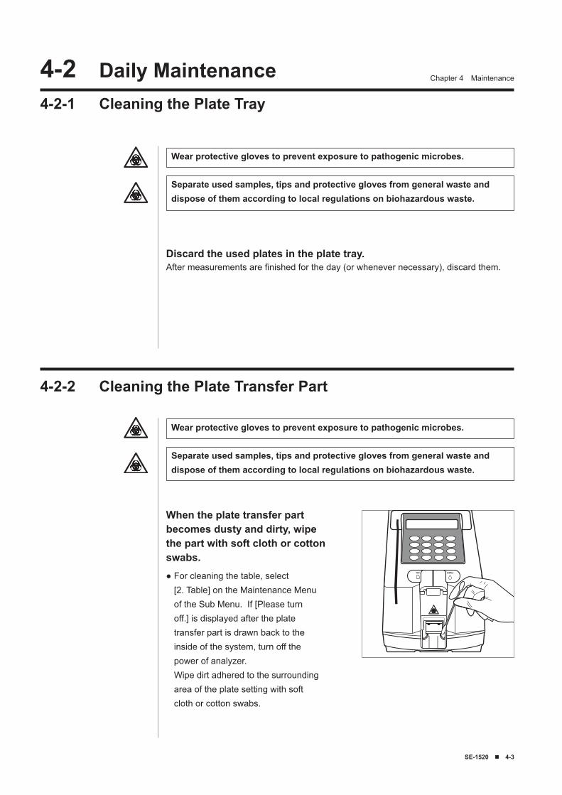
SE-1520 ■ �-�
Chapter 4 Maintenance�-2 Daily Maintenance4-2-1 Cleaning the Plate Tray
Wear protective gloves to prevent exposure to pathogenic microbes.
Separate used samples, tips and protective gloves from general waste and dispose of them according to local regulations on biohazardous waste.
When the plate transfer part becomes dusty and dirty, wipe the part with soft cloth or cotton swabs.
Discard the used plates in the plate tray.After measurements are finished for the day (or whenever necessary), discard them.
4-2-2 Cleaning the Plate Transfer Part
For cleaning the table, select [2. Table] on the Maintenance Menu of the Sub Menu. If [Please turn off.] is displayed after the plate transfer part is drawn back to the inside of the system, turn off the power of analyzer. Wipe dirt adhered to the surrounding area of the plate setting with soft cloth or cotton swabs.
●
Wear protective gloves to prevent exposure to pathogenic microbes.
Separate used samples, tips and protective gloves from general waste and dispose of them according to local regulations on biohazardous waste.
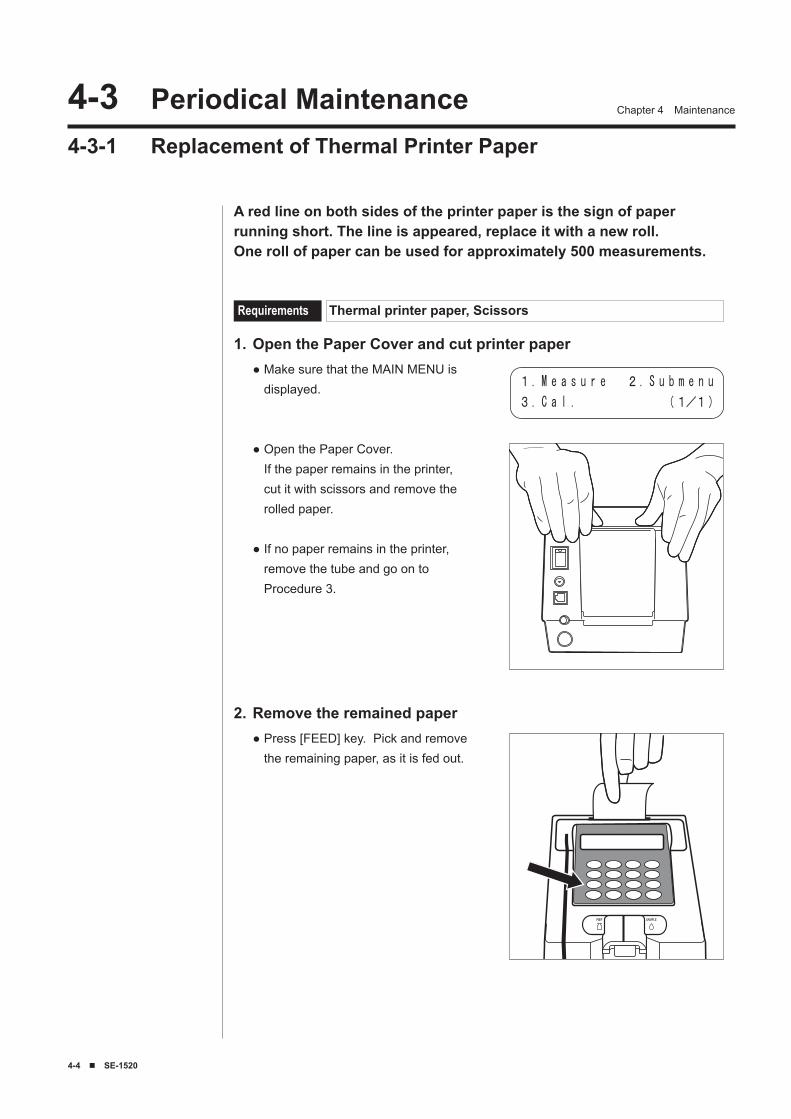
�-� ■ SE-1520
Chapter 4 Maintenance�-� Periodical Maintenance4-3-1 Replacement of Thermal Printer Paper
A red line on both sides of the printer paper is the sign of paper running short. The line is appeared, replace it with a new roll. One roll of paper can be used for approximately 500 measurements.
Open the Paper Cover and cut printer paper1.Make sure that the MAIN MENU is displayed.
Open the Paper Cover. If the paper remains in the printer, cut it with scissors and remove the rolled paper.
If no paper remains in the printer, remove the tube and go on to Procedure 3.
●
●
●
Remove the remained paper2.Press [FEED] key. Pick and remove the remaining paper, as it is fed out.
●
Requirements Thermal printer paper, Scissors
1. M e a s u r e 2. S u b m e n u
3. C a l . (1/1)
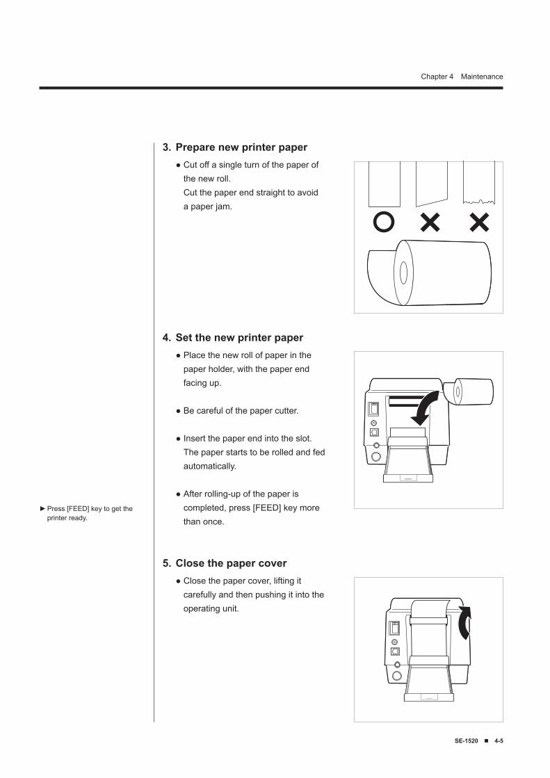
SE-1520 ■ �-5
Chapter 4 Maintenance
Set the new printer paper4.Place the new roll of paper in the paper holder, with the paper end facing up.
Be careful of the paper cutter.
Insert the paper end into the slot. The paper starts to be rolled and fed automatically.
After rolling-up of the paper is completed, press [FEED] key more than once.
●
●
●
●
Close the paper cover5.Close the paper cover, lifting it carefully and then pushing it into the operating unit.
●
Prepare new printer paper3.Cut off a single turn of the paper of the new roll. Cut the paper end straight to avoid a paper jam.
●
Press [FEED] key to get the printer ready.
►
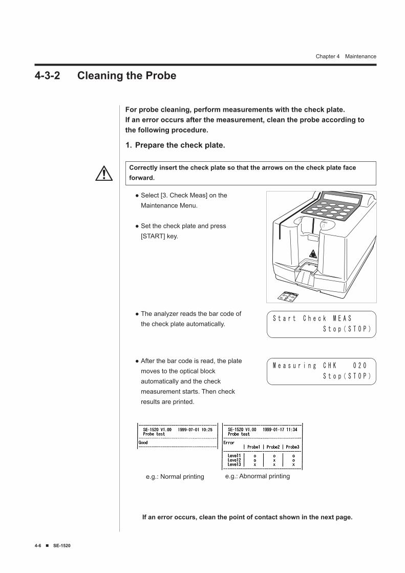
�-� ■ SE-1520
Chapter 4 Maintenance
4-3-2 Cleaning the Probe
Correctly insert the check plate so that the arrows on the check plate face forward.
Prepare the check plate.1.
The analyzer reads the bar code of the check plate automatically.
●S t a r t C h e c k M E A S
S t o p( S T O P )
After the bar code is read, the plate moves to the optical block automatically and the check measurement starts. Then check results are printed.
●M e a s u r i n g C H K 0 2 0
S t o p( S T O P )
If an error occurs, clean the point of contact shown in the next page.
e.g.: Normal printing e.g.: Abnormal printing
Select [3. Check Meas] on the Maintenance Menu.
Set the check plate and press [START] key.
●
●
For probe cleaning, perform measurements with the check plate.If an error occurs after the measurement, clean the probe according to the following procedure.
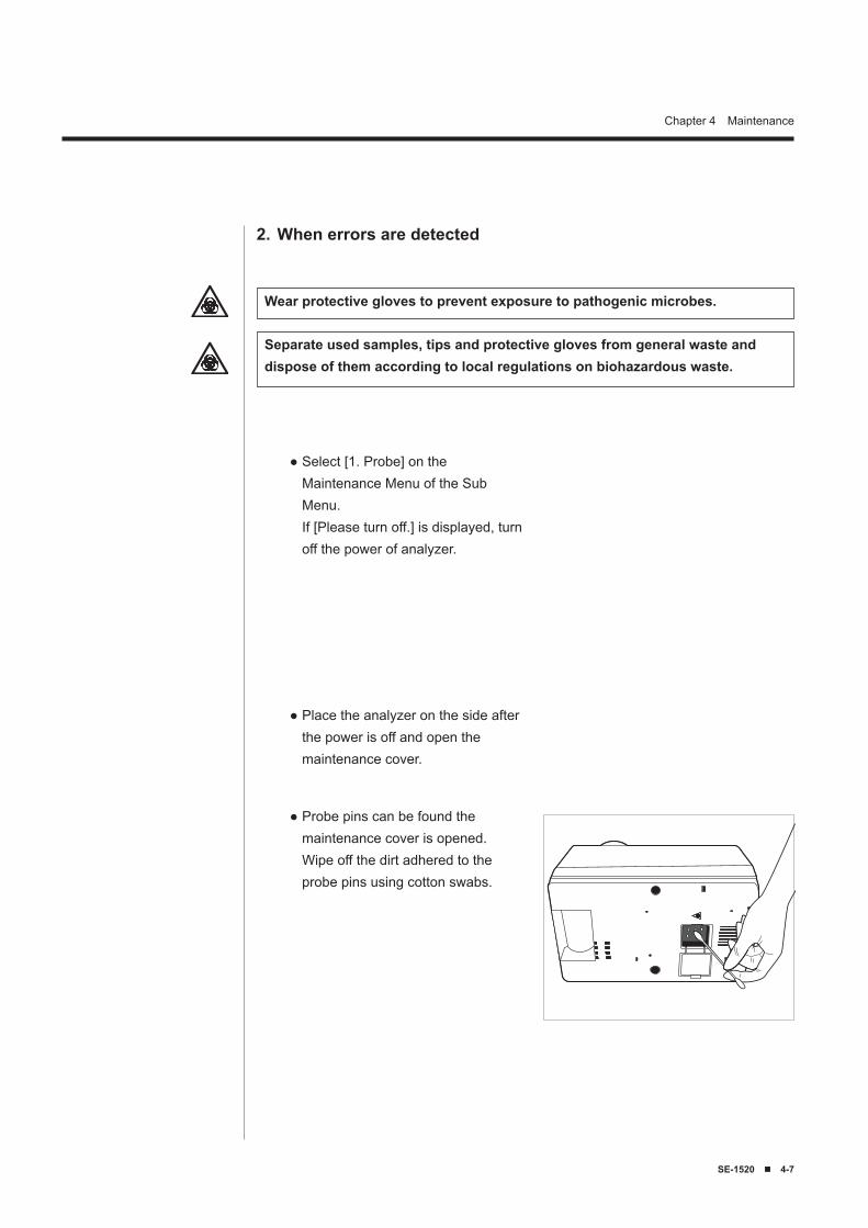
SE-1520 ■ �-7
Chapter 4 Maintenance
When errors are detected2.
Place the analyzer on the side after the power is off and open the maintenance cover.
●
Probe pins can be found the maintenance cover is opened. Wipe off the dirt adhered to the probe pins using cotton swabs.
●
Select [1. Probe] on the Maintenance Menu of the Sub Menu. If [Please turn off.] is displayed, turn off the power of analyzer.
●
Wear protective gloves to prevent exposure to pathogenic microbes.
Separate used samples, tips and protective gloves from general waste and dispose of them according to local regulations on biohazardous waste.
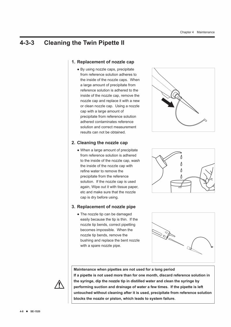
�-8 ■ SE-1520
Chapter 4 Maintenance
Replacement of nozzle cap1.By using nozzle caps, precipitate from reference solution adheres to the inside of the nozzle caps. When a large amount of precipitate from reference solution is adhered to the inside of the nozzle cap, remove the nozzle cap and replace it with a new or clean nozzle cap. Using a nozzle cap with a large amount of precipitate from reference solution adhered contaminates reference solution and correct measurement results can not be obtained.
●
4-3-3 Cleaning the Twin Pipette II
Maintenance when pipettes are not used for a long periodIf a pipette is not used more than for one month, discard reference solution in the syringe, dip the nozzle tip in distilled water and clean the syringe by performing suction and drainage of water a few times. If the pipette is left untouched without cleaning after it is used, precipitate from reference solution blocks the nozzle or piston, which leads to system failure.
Replacement of nozzle pipe3.The nozzle tip can be damaged easily because the tip is thin. If the nozzle tip bends, correct pipetting becomes impossible. When the nozzle tip bends, remove the bushing and replace the bent nozzle with a spare nozzle pipe.
●
Cleaning the nozzle cap2.When a large amount of precipitate from reference solution is adhered to the inside of the nozzle cap, wash the inside of the nozzle cap with refine water to remove the precipitate from the reference solution. If the nozzle cap is used again, Wipe out it with tissue paper, etc and make sure that the nozzle cap is dry before using.
●
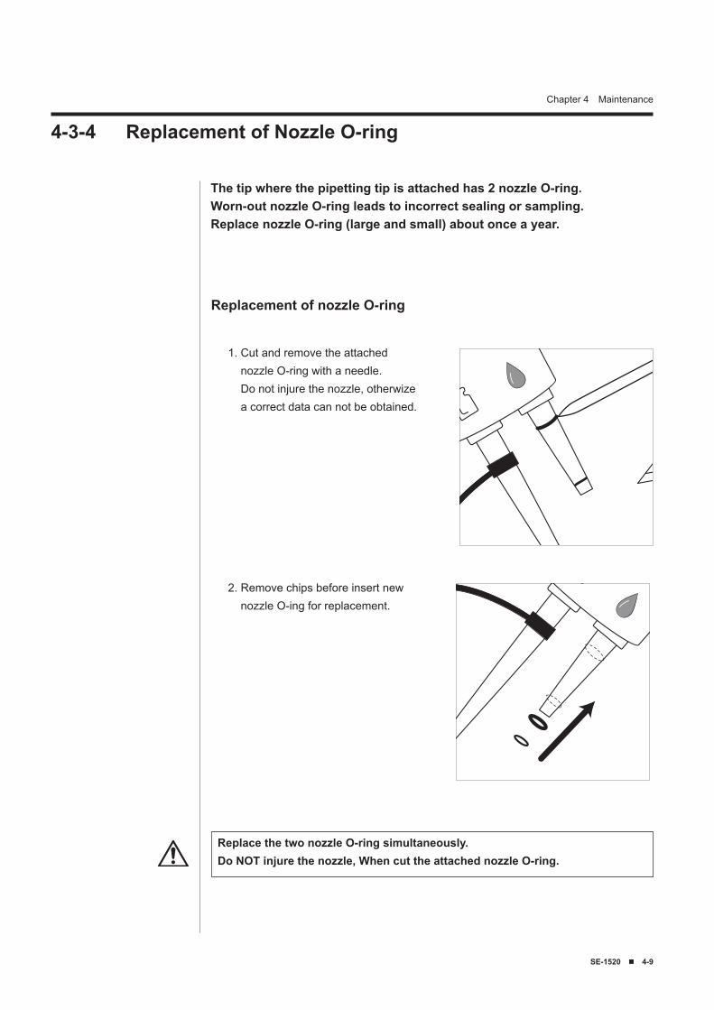
SE-1520 ■ �-9
Chapter 4 Maintenance
4-3-4 Replacement of Nozzle O-ring
The tip where the pipetting tip is attached has 2 nozzle O-ring.Worn-out nozzle O-ring leads to incorrect sealing or sampling.Replace nozzle O-ring (large and small) about once a year.
1. Cut and remove the attached nozzle O-ring with a needle. Do not injure the nozzle, otherwize a correct data can not be obtained.
Replacement of nozzle O-ring
2. Remove chips before insert new nozzle O-ing for replacement.
Replace the two nozzle O-ring simultaneously.Do NOT injure the nozzle, When cut the attached nozzle O-ring.

�-10 ■ SE-1520
Chapter 4 Maintenance
SE-1520 ■ 5-1
Chapter 5
Troubleshooting5-1 Error Messages5-2 Trouble Messages
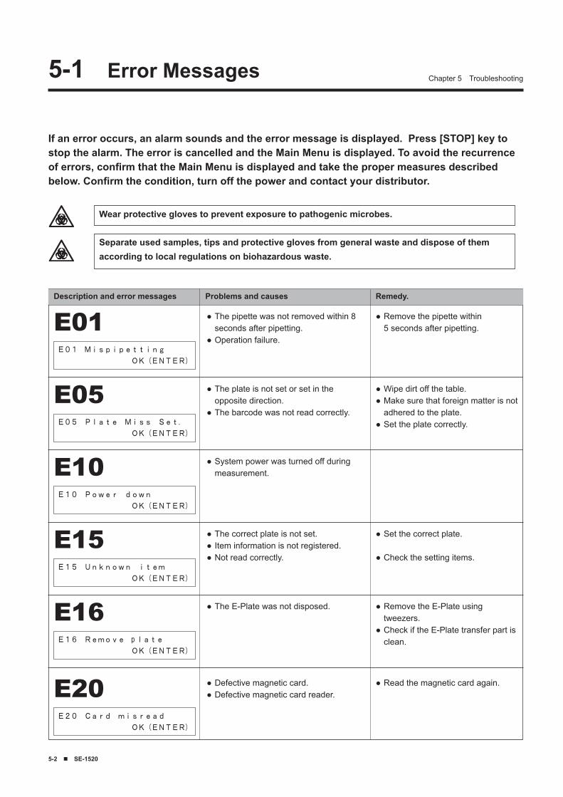
5-2 ■ SE-1520
Chapter 5 Troubleshooting
If an error occurs, an alarm sounds and the error message is displayed. Press [STOP] key to stop the alarm. The error is cancelled and the Main Menu is displayed. To avoid the recurrence of errors, confirm that the Main Menu is displayed and take the proper measures described below. Confirm the condition, turn off the power and contact your distributor.
Description and error messages Problems and causes Remedy.
5-1 Error Messages
The pipette was not removed within 8 seconds after pipetting.Operation failure.
●
●
Remove the pipette within 5 seconds after pipetting.
●E01E01 Mispipetting
OK(ENTER)
The plate is not set or set in the opposite direction.The barcode was not read correctly.
●
●
Wipe dirt off the table.Make sure that foreign matter is not adhered to the plate.Set the plate correctly.
●●
●
E05E05 Plate Miss Set.
OK(ENTER)
System power was turned off during measurement.
●E10E10 Power down
OK(ENTER)
The correct plate is not set.Item information is not registered.Not read correctly.
●●●
Set the correct plate.
Check the setting items.
●
●E15E15 Unknown item
OK(ENTER)
The E-Plate was not disposed.● Remove the E-Plate using tweezers.Check if the E-Plate transfer part is clean.
●
●E16E16 Remove plate
OK(ENTER)
Wear protective gloves to prevent exposure to pathogenic microbes.
Separate used samples, tips and protective gloves from general waste and dispose of them according to local regulations on biohazardous waste.
Defective magnetic card.Defective magnetic card reader.
●●
Read the magnetic card again.●E20E20 Card misread
OK(ENTER)
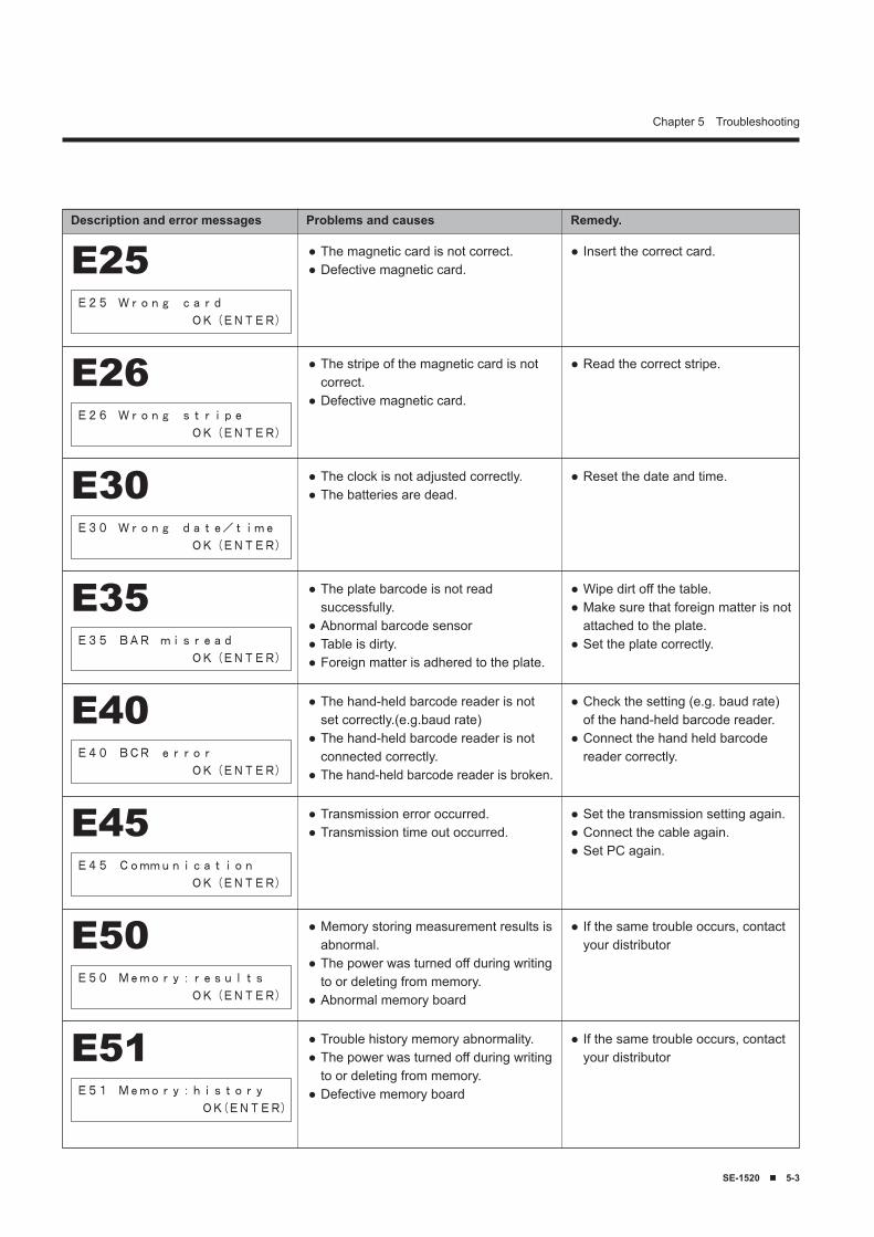
SE-1520 ■ 5-�
Chapter 5 Troubleshooting
Description and error messages Problems and causes Remedy.
The magnetic card is not correct.Defective magnetic card.
●●
Insert the correct card.●E25E25 Wrong card
OK(ENTER)
The stripe of the magnetic card is not correct.Defective magnetic card.
●
●
Read the correct stripe.●E26E26 Wrong stripe
OK(ENTER)
The clock is not adjusted correctly.The batteries are dead.
●●
Reset the date and time.●E30E30 Wrong date/time
OK(ENTER)
The plate barcode is not read successfully.Abnormal barcode sensorTable is dirty.Foreign matter is adhered to the plate.
●
●●●
Wipe dirt off the table.Make sure that foreign matter is not attached to the plate.Set the plate correctly.
●●
●
E35E35 BAR misread
OK(ENTER)
The hand-held barcode reader is not set correctly.(e.g.baud rate) The hand-held barcode reader is not connected correctly.The hand-held barcode reader is broken.
●
●
●
Check the setting (e.g. baud rate) of the hand-held barcode reader.Connect the hand held barcode reader correctly.
●
●E40E40 BCR error
OK(ENTER)
Transmission error occurred.Transmission time out occurred.
●●
Set the transmission setting again.Connect the cable again.Set PC again.
●●●
E45E45 Communication
OK(ENTER)
Memory storing measurement results is abnormal.The power was turned off during writing to or deleting from memory.Abnormal memory board
●
●
●
If the same trouble occurs, contact your distributor
●E50E50 Memory:results
OK(ENTER)
Trouble history memory abnormality. The power was turned off during writing to or deleting from memory.Defective memory board
●●
●
If the same trouble occurs, contact your distributor
●E51E51 Memory:history
OK(ENTER)
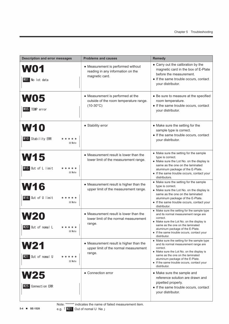
5-� ■ SE-1520
Chapter 5 Troubleshooting
Description and error messages Problems and causes Remedy
Measurement is performed without reading in any information on the magnetic card.
● Carry out the calibration by the magnetic card in the box of E-Plate before the measurement.If the same trouble occurs, contact your distributor.
●
●
W01 No lot data
Measurement is performed at the outside of the room temperature range. (10-30°C)
● Be sure to measure at the specified room temperature.If the same trouble occurs, contact your distributor.
●
●W05 TEMP error
Stability error● Make sure the setting for the sample type is correct.If the same trouble occurs, contact your distributor.
●
●W10 Stability ERR *****
Measurement result is lower than the lower limit of the measurement range.
● Make sure the setting for the sample type is correct.Make sure the Lot No. on the display is same as the one on the laminated aluminum package of the E-Plate.If the same trouble occurs, contact your distributors.
●
●
●
W15 Out of L limit *****
Measurement result is higher than the upper limit of the measurement range.
●Make sure the setting for the sample type is correct.Make sure the Lot No. on the display is same as the one on the laminated aluminum package of the E-Plate.If the same trouble occurs, contact your distributor.
●
●
●
W16 Out of U limit *****
Measurement result is lower than the lower limit of the normal measurement range.
●Make sure the setting for the sample type and its normal measurement range are correct.Make sure the Lot No. on the display is same as the one on the laminated aluminum package of the E-Plate.If the same trouble occurs, contact your distributor.
●
●
●
W20 Out of nomal L *****
Measurement result is higher than the upper limit of the normal measurement range.
●Make sure the setting for the sample type and its normal measurement range are correct.Make sure the Lot No. on the display is same as the one on the laminated aluminum package of the E-Plate.If the same trouble occurs, contact your distributor.
●
●
●
W21 Out of nomal U *****
Connection error● Make sure the sample and reference solution are drawn and pipetted properly.If the same trouble occurs, contact your distributor.
●
●
W25 Connection ERR
※Note
※ Note
※ Note
※ Note
※ Note
Note: "*****" indicates the name of failed measurement item. e.g.「 Out of nomal U Na 」
W01
W05
W10
W15
W16
W20
W21
W25
W21
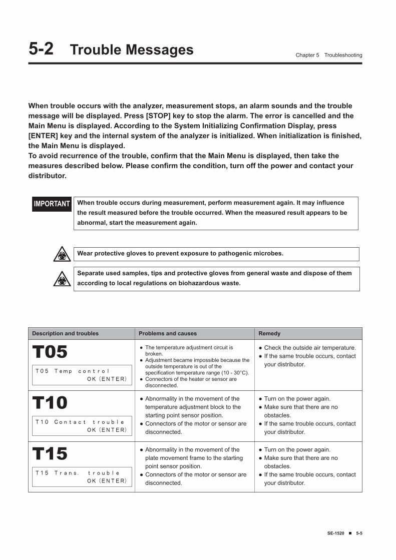
SE-1520 ■ 5-5
Chapter 5 Troubleshooting5-2 Trouble Messages
When trouble occurs with the analyzer, measurement stops, an alarm sounds and the trouble message will be displayed. Press [STOP] key to stop the alarm. The error is cancelled and the Main Menu is displayed. According to the System Initializing Confirmation Display, press [ENTER] key and the internal system of the analyzer is initialized. When initialization is finished, the Main Menu is displayed. To avoid recurrence of the trouble, confirm that the Main Menu is displayed, then take the measures described below. Please confirm the condition, turn off the power and contact your distributor.
Description and troubles Problems and causes Remedy
When trouble occurs during measurement, perform measurement again. It may influence the result measured before the trouble occurred. When the measured result appears to be abnormal, start the measurement again.
IMPORTANT
The temperature adjustment circuit is broken.Adjustment became impossible because the outside temperature is out of the specification temperature range (10 - 30°C).Connectors of the heater or sensor are disconnected.
●
●
●
Check the outside air temperature.If the same trouble occurs, contact your distributor.
●●T05
T05 Temp control
OK(ENTER)
Abnormality in the movement of the temperature adjustment block to the starting point sensor position.Connectors of the motor or sensor are disconnected.
●
●
Turn on the power again.Make sure that there are no obstacles.If the same trouble occurs, contact your distributor.
●●
●
T10T10 Contact trouble
OK(ENTER)
Abnormality in the movement of the plate movement frame to the starting point sensor position.Connectors of the motor or sensor are disconnected.
●
●
Turn on the power again.Make sure that there are no obstacles.If the same trouble occurs, contact your distributor.
●●
●
T15T15 Trans. trouble
OK(ENTER)
Wear protective gloves to prevent exposure to pathogenic microbes.
Separate used samples, tips and protective gloves from general waste and dispose of them according to local regulations on biohazardous waste.
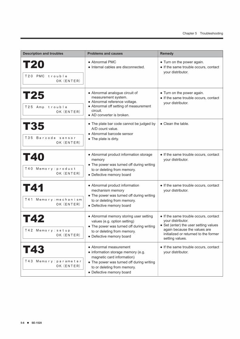
5-� ■ SE-1520
Chapter 5 Troubleshooting
Description and troubles Problems and causes Remedy
Abnormal PMCInternal cables are disconnected.
●●
Turn on the power again.If the same trouble occurs, contact your distributor.
●●T20
T20 PMC trouble
OK(ENTER)
Abnormal analogue circuit of measurement system.Abnormal reference voltage. Abnormal off setting of measurement circuit.AD converter is broken.
●
●●
●
Turn on the power again.If the same trouble occurs, contact your distributor.
●●T25
T25 Amp trouble
OK(ENTER)
The plate bar code cannot be judged by A/D count value.Abnormal barcode sensorThe plate is dirty.
●
●●
Clean the table.●T35T35 Barcode sensor
OK(ENTER)
Abnormal product information storage memoryThe power was turned off during writing to or deleting from memory.Defective memory board
●
●
●
If the same trouble occurs, contact your distributor.
●T40T40 Memory:product
OK(ENTER)
Abnormal product information mechanism memoryThe power was turned off during writing to or deleting from memory.Defective memory board
●
●
●
If the same trouble occurs, contact your distributor.
●T41T41 Memory:mechanism
OK(ENTER)
Abnormal memory storing user setting values (e.g. option setting)The power was turned off during writing to or deleting from memory.Defective memory board
●
●
●
If the same trouble occurs, contact your distributor.Set (enter) the user setting values again because the values are initialized or returned to the former setting values.
●
●T42T42 Memory:setup
OK(ENTER)
Abnormal measurementinformation storage memory (e.g. magnetic card information)The power was turned off during writing to or deleting from memory.Defective memory board
●●
●
●
If the same trouble occurs, contact your distributor.
●T43T43 Memory:parameter
OK(ENTER)
SE-1520 ■ �-1
Chapter 6
Appendix6-1 Transmission Specifications
6-1-1 External Output Format6-1-2 Block Structure6-1-3 Format of Measurement Results
6-2 After-sales Service
�-2 ■ SE-1520
Chapter 6 Appendix
External output format
Transmission format
Data format
Baud rate
Hand shake
Time gap
Forcible termination
Bit-serial output in compliance with RS-232 C
Start-stop system (asynchronous)
One character is composed of the following 11 bits.Start bit: 1 bitData bit: 7 bit (ASCII code)Parity bit: 1 bit (even parity)Stop bit: 2 bit
9600 bps
Control by CTS or RTS is possible. (By default setting, this control is not performed.)XON/XOFF control is not available.
Two second waiting time is inserted between each block (from<ETX> to <STX>).
Data transmission may be interrupted forcibly by key operation. It is not promptly suspended by pressing a key, but transmission continues until <ETX> is output.
�-1 Transmission Specifications6-1-1 External Output Format
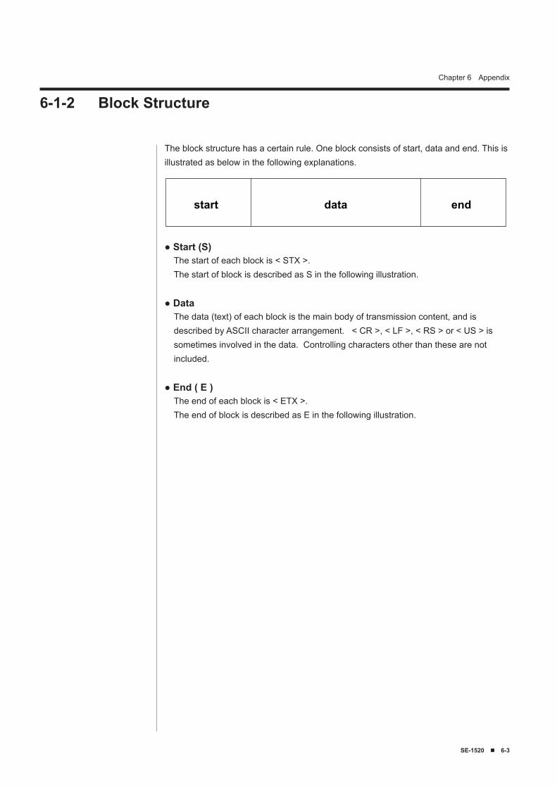
SE-1520 ■ �-�
Chapter 6 Appendix
6-1-2 Block Structure
The block structure has a certain rule. One block consists of start, data and end. This is illustrated as below in the following explanations.
● Start (S)The start of each block is < STX >.The start of block is described as S in the following illustration.
● DataThe data (text) of each block is the main body of transmission content, and is described by ASCII character arrangement. < CR >, < LF >, < RS > or < US > is sometimes involved in the data. Controlling characters other than these are not included.
● End ( E )The end of each block is < ETX >.The end of block is described as E in the following illustration.
start enddata
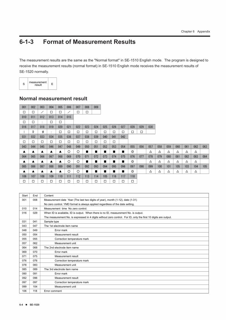
�-� ■ SE-1520
Chapter 6 Appendix
Normal measurement result
The measurement results are the same as the "Normal format" in SE-1510 English mode. The program is designed to receive the measurement results (normal format) in SE-1510 English mode receives the measurement results of SE-1520 normally.
001
□
010
□
016
I
031
□
043
▲
064
▲
085
▲
106
□
002
□
011
□
017
D
032
□
044
▲
065
▲
086
▲
107
□
003
/
012
:
018
♯
033
□
045
▲
066
▲
087
▲
108
□
004
□
013
□
019
:
034
□
046
▲
067
▲
088
▲
109
□
005
□
014
□
020
□
035
□
047
▲
068
▲
089
▲
110
□
006
/
015
021
□
036
□
048
○
069
○
090
○
111
□
007
□
022
□
037
□
049
○
070
○
091
○
112
□
008
□
023
□
038
□
050
■
071
■
092
■
113
□
009
024
□
039
□
051
■
072
■
093
■
114
□
025
□
040
□
052
■
073
■
094
■
105
□
026
□
041
□
053
■
074
■
095
■
116
□
027
□
042
054
■
075
■
096
■
117
□
028
□
055
◎
076
◎
097
◎
118
□
029
□
056
077
098
030
057
△
078
△
099
△
058
△
079
△
100
△
059
△
080
△
101
△
060
△
081
△
105
△
061
△
082
△
103
△
062
△
083
△
104
△
063
084
105
6-1-3 Format of Measurement Results
S Emeasurementresult
Start001
010016
031043048050055057064069071076078085090092097099106
End008
014029
041047049054055062068070075076083089091096097104118
ContentMeasurement date Year (The last two digits of year), month (1-12), date (1-31)No zero control. YMD format is always applied regardless of the date setting.Measurement time No zero control.When ID is available, ID is output. When there is no ID, measurement No. is output.The measurement No. is expressed in 4 digits without zero control. For ID, only the first 10 digits are output.Sample typeThe 1st electrode item name Error mark Measurement result Correction temperature mark Measurement unitThe 2nd electrode item name Error mark Measurement result Correction temperature mark Measurement unitThe 3rd electrode item name Error mark Measurement result Correction temperature mark Measurement unitError comment
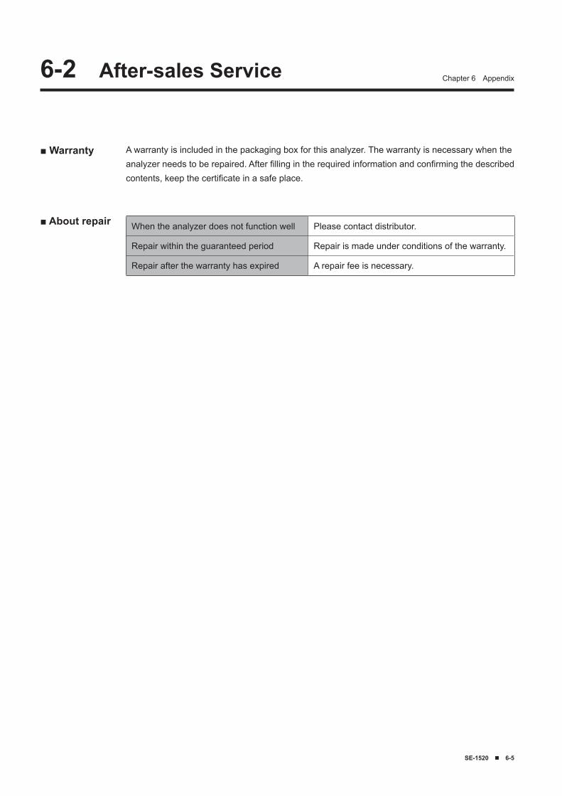
SE-1520 ■ �-5
Chapter 6 Appendix
■ Warranty A warranty is included in the packaging box for this analyzer. The warranty is necessary when the analyzer needs to be repaired. After filling in the required information and confirming the described contents, keep the certificate in a safe place.
■ About repair
�-2 After-sales Service
When the analyzer does not function well Please contact distributor.
Repair within the guaranteed period Repair is made under conditions of the warranty.
Repair after the warranty has expired A repair fee is necessary.

84-03867P/N 7842-00Rev. 03/11
