manual for installation and operating - rotork.com · all nbr seals subject to rotating parts are...
TRANSCRIPT
Rotork Gears BV - Nijverheidstraat 25 - 7581 PV Losser The Netherlands - Tel: +31 (0)53 5388677 - Fax: +31 (0)535383939
Mail: [email protected] - Web: www.rotork.com
PUB039-003-00_1214
MANUAL
FOR
INSTALLATION
AND
OPERATING
For gearbox model ILG/S
ILG/S gearbox manual
Rotork Gears BV - Nijverheidstraat 25 - 7581 PV Losser The Netherlands - Tel: +31 (0)53 5388677 - Fax: +31 (0)535383939
Mail: [email protected] - Web: www.rotork.com
PUB039-003-00_1214
2
1.Preface .................................................................................................................................................................. 3 1.1 Introduction. ...................................................................................................................................................... 3 2. Technical data and specifications ........................................................................................................................ 3 3. Handling and safety precautions ......................................................................................................................... 4 3.1 Qualification of staff ......................................................................................................................................... 4 3.2 Commissioning ................................................................................................................................................. 4 3.3 Operation ........................................................................................................................................................... 4 3.4 Protective measures ........................................................................................................................................... 4 3.5 Maintenance ...................................................................................................................................................... 4 3.6 Storage .............................................................................................................................................................. 4 3.7 Long-term storage ............................................................................................................................................. 4 3.8 Packing .............................................................................................................................................................. 5 3.9 Handling ............................................................................................................................................................ 5 3.10 IP rating and environmental conditions ........................................................................................................... 5 3.11 Stem shaft water ingress .................................................................................................................................. 5 3.12 Paint ................................................................................................................................................................ 5 3.13 Primer .............................................................................................................................................................. 5 3.14 Seals ................................................................................................................................................................ 5 3.15 Grease ............................................................................................................................................................. 5 3.16 Correct use ...................................................................................................................................................... 6 3.17 Installation and operating ................................................................................................................................ 6 3.18 Disposal ........................................................................................................................................................... 6 3.19 Identification ................................................................................................................................................... 6 3.20 Handweel type ................................................................................................................................................. 6 3.21 Drive options and bottom side PCD options ................................................................................................... 7 4.Installation: mounting to the valve ....................................................................................................................... 7 5. Mounting instructions chainwheel ...................................................................................................................... 9 6.Adjustment of the stopscrews ............................................................................................................................ 11 Table 4: Tighten force in Nm ................................................................................................................................ 12 7.Operating ............................................................................................................................................................ 13 8. Number of turns opening or closing .................................................................................................................. 14 9. Standard conditions ........................................................................................................................................... 15 10. IP Rating ......................................................................................................................................................... 17 11.Certificates ....................................................................................................................................................... 18 12.Reach ................................................................................................................................................................ 19

ILG/S gearbox manual
Rotork Gears BV - Nijverheidstraat 25 - 7581 PV Losser The Netherlands - Tel: +31 (0)53 5388677 - Fax: +31 (0)535383939
Mail: [email protected] - Web: www.rotork.com
PUB039-003-00_1214
3
1. Preface
1.1 Introduction. Rotork Gears BV produces gearboxes of different types and sizes. The ILG/S gearbox from Rotork Gears is a
manual override quarter turn gearbox for single acting actuators. The ILG/S gearbox is intended to be used for
the manual operation of valves in pipelines, in case of failure of the automatic actuator system.
NB. This manual is valid only for the standard ILG/S gearboxes of Rotork Gears BV. For special versions, the
specifications and model can differ. Rotork Gears BV is not responsible for any damage caused by incorrect use
of the gearbox.
2. Technical data and specifications 2.1 Maximum allowable input- and output torque
Gearbox
connection
to actuator connection to valve Max. Torque [Nm]
size ISO 5211 ISO 5211/1 Inputshaft Output
ILG/S 210 (LB) F05-F07-F10 F05-F07-F10(-F12) 28.5 330
ILG/S 550 (LB) F07-F10-F12 F07-F10-F12-F14(-F16) 78 934
ILG/S 880 (LB) F10-F12-F14 F10-F12-F14-F16 123 1620
ILG/S 1250 (LB) F12-F14-F16 F10-F12-F14-F16(-F25) 139 2640
ILG/S 1950 (LB) F16-F25 F12-F14-F16-F25(-F30) 160 3050
ILG/S 1950 SP4 (LB) F16-F25 F12-F14-F16-F25(-F30) 103 6800
ILG/S 1950 PR4 (LB) F16-F25 F12-F14-F16-F25(-F30) 103 6800
ILG/S 6800 (LB) F25-F30 F16-F25-F30(-F35) 160 4400
ILG/S 6800 SP4 (LB) F25-F30 F16-F25-F30(-F35) 134 12500
ILG/S 6800 PR4 (LB) F25-F30 F16-F25-F30(-F35) 130 12500
ILG/S 6800 SP6 (LB) F25-F30 F16-F25-F30(-F35) 108 17000
ILG/S 6800 PR6 (LB) F25-F30 F16-F25-F30(-F35) 121 17000
ILG/S 200 SP9 F25-F30-F35 F25-F30-F35 166 26000
ILG/S 200 PR10 F25-F30-F35 F25-F30-F35 124 26000
ILG/S 250 SP9 F25-F30-F35 F25-F30-F35-F40 142 32000
ILG/S 250 PR10 F25-F30-F35 F25-F30-F35-F40 142 32000
Table 1 : Connection data of the gearbox
For more specified information, you can contact our sales department.

ILG/S gearbox manual
Rotork Gears BV - Nijverheidstraat 25 - 7581 PV Losser The Netherlands - Tel: +31 (0)53 5388677 - Fax: +31 (0)535383939
Mail: [email protected] - Web: www.rotork.com
PUB039-003-00_1214
4
3. Handling and safety precautions Be sure to read and understand this manual before installation and use of our gearboxes. All personnel working
with this gearbox must be familiar with the instructions in this manual and observe the instructions given. Safety
instructions must be observed to avoid personal injury or property damage.
3.1 Qualification of staff
Assembly, commissioning, operation, and maintenance must be carried out exclusively by suitably qualified
personnel authorised by the end user or contractor. Prior to working on this product, the staff must have
thoroughly read and understood these instructions and, furthermore, know and observe officially recognised
rules regarding occupational health and safety. Work performed in explosive atmospheres is subject to special
regulations which have to be observed. The end user or contractor is responsible for respect and control of these
regulations, standards, and laws.
3.2 Commissioning
Prior to commissioning, it is important to check that all settings are in compliance with the requirements of the
application. Incorrect settings might present a danger to the application, e.g. cause damage to the valve or the
installation. The manufacturer will not be held liable for any consequential damage. Such risk lies entirely with
the user.
3.3 Operation
Prerequisites for safe and smooth operation:
Correct transport, proper storage, mounting and installation, as well as careful commissioning.
Only operate the gearbox if it is in perfect condition while observing these instructions.
Immediately notify Rotork Gears BV about any faults and damage and allow for corrective measures.
Observe recognised rules for occupational health and safety. Observe the national regulations.
3.4 Protective measures
The end user or the contractor is responsible for implementing the required protective measures on site, such as
enclosures, barriers or personal safety equipment for the staff.
3.5 Maintenance
To ensure reliable gearbox operation, the maintenance instructions included in this manual must be observed.
Any gearbox modification requires the consent of the manufacturer. A Rotork Gears BV gearbox requires only
little maintenance. To ensure that the gearbox is always ready to operate, we recommend for gearboxes the
following measures. Three (3) months after commissioning and each year:
- Check the bolts on top of the gearbox;
- Check the bolts on the valve flange;
- Perform a test run every six months;
- Check the gearbox for leakage of grease;
- For gearboxes with permanently vibration and exposure above 60ºC, checks should be performed at shorter
intervals.
3.6 Storage
The gearboxes need to be stored inside in a safe way to avoid accidents. Also avoid storage in areas subjected to
high temperature extremes and /or areas subjected to large amounts of humidity and dust. Protect against floor
dampness by storage on a shelf or on a wooden pallet. Apply suitable corrosion protection agent to bare surfaces.
3.7 Long-term storage
If the Gearbox must be stored for a long period (more than 6 months) the following points must be observed.
Prior to storage:
Protect uncoated surfaces, in particular the output drive parts and mounting surface, with long-term
corrosion protection agent.
At an interval of approximately 6 months:
Check for corrosion. If first signs of corrosion show, apply new corrosion protection.

ILG/S gearbox manual
Rotork Gears BV - Nijverheidstraat 25 - 7581 PV Losser The Netherlands - Tel: +31 (0)53 5388677 - Fax: +31 (0)535383939
Mail: [email protected] - Web: www.rotork.com
PUB039-003-00_1214
5
3.8 Packing
Our products are protected and packed by special packaging for the transport ex works. The packaging consists
of environmentally friendly materials which can easily be separated and recycled. We use the following
packaging material: wood, cardboard, paper, and PE foil. For the disposal of the packaging material, we
recommend recycling and collection centres.
3.9 Handling
Never drop the gearbox or otherwise subject it to strong impact. Lift the gearbox horizontal on the valve. The
input shaft or hand wheel cannot be used for lifting the gearbox. Do not lift the gearbox when it is assembled to
the valve
3.10 IP rating and environmental conditions
The enclosure protection IP65 (on request 67 and 68) only refers to the interior of the gearboxes and not to the
stem shaft coupling compartment. (See table. 6 - IP rating) The Rotork Gears ILG/D gearboxes can be used at
ambient temperatures from –20 to + 120°C. Other temperature ranges are available on request. Suitability for
any specific application is not claimed. IP rating is done in accordance to a standard test protocol. It is
recommended that users carry out tailor made tests to prove the product is fit for purpose for the specific
environmental conditions. For example marine environment, tropical conditions, cold or very hot conditions,
chemical sites with acids or salty conditions requires the end user to assess the fit for purpose.
When the product is used in areas with high temperature fluctuations it is recommended to use pressure
compensators to prevent pressure differences between the outside environment and the interior of the gearbox.
3.11 Stem shaft water ingress
Water can enter into the coupling compartment along the valve shaft, this would lead to corrosion. Therefore a
suitable anticorrosive (or sticky grease) must be applied on the inside top bore hole of the gearbox and coupling
before mounting. When water ingress protection towards the stem shaft is required, we recommend to use a
liquid sealing on top and bottom of the flange side from the gearbox.
3.12 Paint
We deliver our gearboxes in different RAL colours, our standard average paint thickness is 60 microns, suitable
for installation in a clean and dry industrial indoor environment. Our process consists of a phosphating pre-
treatment followed by our standard DTM (direct to metal) paint system (Polyaspartic) or primer paint. Other
paint systems are on request. For exposure to corrosive outside environment and other non-standard
environments, paint system are to be advised by the customer including IP rating. On request we can deliver
other paint systems and thicknesses (see table 5 standard conditions and options)
3.13 Primer
On request we deliver gearboxes in primer. Standard primer is a 1K industry primer which has a maximal
lifetime of 1, 5 month and must be stored only in indoor, clean and dry conditions. On request zinc primer can be
supplied which has a maximal lifetime of 3 months when free from zinc salts and free from contamination and
stored in a clean exterior. In industrial or marine conditions this should be reduced to the practical minimum.
3.14 Seals
Rotork Gears BV is using a silicone low volatile liquid seal between cover lid and body. Loosening the top bolts
of the cover plate from the gearbox can break the seal resulting to leakage. Rotork Gears BV will not be held
liable when the top bolts are opened without notification. Once opened a new liquid sealing must be applied.
Liquid seals kits may be obtained from Rotork Gears BV. During the order process it should be mentioned when
gearboxes are exposed to high- or low temperatures. Seals made of elastomeric materials are subject to ageing.
All NBR seals subject to rotating parts are lubricated with MI-setral 9-M. Gearboxes up to minus 60 degrees
Celsius are built with special O-rings.
3.15 Grease
Rotork Gears BV is applying grease that is non-self-igniting and do not present an explosion hazard. Dependent
on the environmental conditions different greases can be used such as high temperature grease, silicone free
grease, foodgrade grease or oxygen free grease. Gearboxes for minus 60 degrees Celsius are built with 75%
filling level of grease. Gearboxes are filled for life but on customer request grease nipples are an option to be
mentioned during order process.

ILG/S gearbox manual
Rotork Gears BV - Nijverheidstraat 25 - 7581 PV Losser The Netherlands - Tel: +31 (0)53 5388677 - Fax: +31 (0)535383939
Mail: [email protected] - Web: www.rotork.com
PUB039-003-00_1214
6
3.16 Correct use
Prior to installation, be sure the gearbox will NOT be overloaded during normal use. To verify this the combined
spring torques + safety factor (spring start torque + spring end torque) x 1.2 = required torque. Do not exceed the
values given for the gearbox. For the maximum allowable torque on the gearbox, (see table 1). ILGS gearboxes
can only be used for manual operation.
3.17 Installation and operating
Not observing the rules as stated in this manual, can lead to damage and/or personal injuries. Qualified personnel
must be fully aware of the instructions as described in this manual. Only when the instructions are observed,
correct operation of the gearboxes can be guaranteed.
3.18 Disposal
Never dispose a gearbox at a general disposal site/depot. The gearbox has to be offered to a disposal depot for
recycling. The iron parts can be used for recycling. The seals are of nitrile and can be used for plastic recycling.
The grease may not be discharged to sewer- or surface water. It has to be disposed according to local regulations.
3.19 Identification
Each gearbox has a nameplate. On this nameplate you find the following standard information:
Model type - Rotork Gears BV order.nr with line.nr - Production date and other customer information, when
required.
N.B. Information on the name plate is important and is required in case of non-conformities or requests. In case
of non-conformity, please send a description of the complaint, details from the nameplate with clear
photograph(s) to [email protected].
3.20 Handweel type
Handwheel Type - weight Kgs (lbs)
Size in mm CD
(casted)
PS
(pressed steel)
SG
(Steel welded)
S
(Stainless steel)
F
(Steel welded)
50 0.11 (0.24) - - - -
75 0.21 (0.46) - - - -
100 0.32 (0.71) 0.15 (0.33) - - -
125 0.54 (1.19) 0.2 (0.44) - - -
150 - - 1 (2.20) 0.4 (0.88) -
160 - 0.35 (0.77) - - -
200 1 (2.20) 0.75 (1.65) 1.35 (2.98) 1 (2.20) 1 (2.20)
250 - 1.5 (3.31) 1.4 (3.09) - -
300 - - 1.8 (3.97) - 1.5 (3.31)
315 - 2 (4.41) - - -
350 - - 2.3 (5.07) 1.5 (3.31) -
400 - 3.5 (7.72) 2.8 (6.17) - 2.2 (4.85)
450 - - 3 (6.61) - -
500 - - 3.5 (7.72) - 3 (6.61)
600 - - 4.5 (9.92) - 3.2 (7.05)
700 - - 5 (11.02) - 5.5 (12.13)
800 - - 5.5 (12.13) - 6.6 (14.55)
900 - - 6 (13.23) - 7.2 (15.87)
Table 2. Handwheel type – weight Kgs (lbs)

ILG/S gearbox manual
Rotork Gears BV - Nijverheidstraat 25 - 7581 PV Losser The Netherlands - Tel: +31 (0)53 5388677 - Fax: +31 (0)535383939
Mail: [email protected] - Web: www.rotork.com
PUB039-003-00_1214
7
3.21 Drive options and bottom side PCD options
Figure 1 shows the different drive options. Special drive requirements on request. We deliver ILG/S standard
off-center. On request we can deliver on center with reduced tapping depths and dowel pin holes (See figure 2)
Figure 1. Drive options
Figure 2: Bottom PCD options
4. Installation: mounting to the valve The ILG/S is a manual override quarter turn gearbox for single acting pneumatic or electric actuators. For
maximum allowable input- and output torque, refer to table 1 or the (not included) datasheet. Standard we
deliver our ILG/S gearboxes in left handed position, the gearbox is observed from above (top view) with set
screws pointing downwards. The shaft is than at the top pointing to the left (left handed gearbox)
This manual describes the installation of the gearbox and its parts. The purpose from the ILG/S gearbox is to
open a valve with the gearbox in case of a failing actuator system. If the power supply fails the spring returns the
actuator (and valve) to the “secure” (closed) position.
1. The gearbox is standard delivered in closed position.
2. It is recommended to mount a handwheel or chainwheel on the inputshaft prior to assembling the
gearbox to the valve.
Figure 3: mounting handwheel

ILG/S gearbox manual
Rotork Gears BV - Nijverheidstraat 25 - 7581 PV Losser The Netherlands - Tel: +31 (0)53 5388677 - Fax: +31 (0)535383939
Mail: [email protected] - Web: www.rotork.com
PUB039-003-00_1214
8
3. Check if the bolt circle of the flanges (of gearbox and valve) coincide. Also check if the valve stem and
the bore of the driveshaft match.
4. Make sure the valve is in the fully closed position. If not, close the valve before continuing.
5. For fail-close actuators (90° clockwise close), the gearbox has to be positioned fully closed. This is
achieved by turning the handwheel clockwise.
6. In case of use of studbolts for fixing the gearbox to the valve, it is recommended to screw them into the
bottom flange of the gearbox prior to mounting the gearbox on top of the valve.
7. The use of a gasket between the flange of the valve and gearbox is recommended. Put the driveshaft
from the bottomside into the gearbox (see figure 4). The size and shape of the connections of the
driveshaft and the gearbox can differ from figure 4.
8. Put the gearbox on top of the valve.
9. The gearbox is mounted perpendicular to the valve (see figure 7).
10. Fix the gearbox to the valve appropriate studs and nuts with washers or bolts. Take into account Table 3
for maximum screw dept. For tightening, refer to standard VDI 2230.
11. The (fail-close = spring-return) actuator can be mounted on top (see chapter 6).
12. The assembly is ready for adjustment (see chapter 6).
13. For another kind of actuator (operation), above mentioned points may not apply to the situation. When
the valve has to be opened with the gearbox in case of a malfunction of the actuator-system, position the
gearbox in the open position and the driveshaft key at '12 o'clock'. Be sure the driveshaft can be freely
turned by the actuator, from close to open, without interfering with the worm wheel.
Figure 4: assembly of driveshaft into gearbox ILG/S
For fail-close actuators -clockwise close- be sure the driveshaft can make a free quarter turn clockwise (seen from the
bottomside) from its endposition; refer to figure 5 (the position of the 'free-run' can differ from the figure). By this the
gearbox can open the valve in case of actuator or power supply failure.
Figure 5: Standard position of driveshaft form A Figure 6: Position of driveshaft optional form B used
for couplings for maximum stem acceptance

ILG/S gearbox manual
Rotork Gears BV - Nijverheidstraat 25 - 7581 PV Losser The Netherlands - Tel: +31 (0)53 5388677 - Fax: +31 (0)535383939
Mail: [email protected] - Web: www.rotork.com
PUB039-003-00_1214
9
Figure 7: Gearbox perpendicular to the valve
PCD F05 F07 F10 F12 F14 F16 F25 F30 F35 F40
Max. screw depth 8 11 13 16 18 18 18 18 30 36
Table 3: maximum screw depth per pitch circle diameter (PCD) for ILG/S range
5. Mounting instructions chainwheel
Following instructions need to be followed for mounting the chainwheel on the shaft. It is advised to use a
suitable anticorrosive (or sticky grease) on the inside bore hole of the chainwheel and guide sleeve. When used
outside or in a wet or humid environment then we recommended the use of a stainless steel shaft for which we
have different classifications to suit several environmental specifications and not a protected or painted C45 steel
shaft. Corrosion between the shaft and the chain guide can cause the combination of the chainwheel and the
guide to fail. When ordering chain please order 2x the necessary operation distance + full diameter of
chainwheel. The chainwheel needs to be sized on the maximum rimpull of 700N.
1. The gearbox is standard delivered in the closed position, setscrews are loosely tightened.
2. It is recommended to mount the chainwheel on the input shaft before assembling the gearbox to the
Valve (see figure 8).
3. Mount item 1, 2, 3, 4 and 5 on the input shaft (see figure 8)
4. Locate the holes of the chainwheel and shaft opposite each other, insert item 6 (slotted springtype
Straightpin) by hammering.
5. Mount item 7b (set screw with cone point) in front of the chainwheel. Optional item 7a (hexagon head
bolt) can be mounted, this for additional locking of the chain wheel. This extra option need to be
ordered in the preliminary stages of the order.
6. Slide item 4, 3, 2 and 1 together and mount item 8 (hexagon head bolt) in tapped hole of item 1 (Axial
disc)
7. Mount the chain after you have fixed the gearbox to the valve. Connect the loose ends of the chain with
the supplied splitlink (see figure 9)

ILG/S gearbox manual
Rotork Gears BV - Nijverheidstraat 25 - 7581 PV Losser The Netherlands - Tel: +31 (0)53 5388677 - Fax: +31 (0)535383939
Mail: [email protected] - Web: www.rotork.com
PUB039-003-00_1214
10
Figure 8: Mounting chainwheel kit
Figure 9: Chain splitlink

ILG/S gearbox manual
Rotork Gears BV - Nijverheidstraat 25 - 7581 PV Losser The Netherlands - Tel: +31 (0)53 5388677 - Fax: +31 (0)535383939
Mail: [email protected] - Web: www.rotork.com
PUB039-003-00_1214
11
6. Adjustment of the stopscrews The gearbox is already mounted on top of the valve (see installation). This manual only applies to fail-close
(clockwise) actuators.
1. Be sure gearbox and valve are in fully closed position. If not, turn the gearbox in opened position by
turning the handwheel clockwise.
2. Turn the valve in the fully closed position.
3. Mount the (spring-clockwise-return) actuator. Do not pressurize the actuator! Be sure the actuator is
ready for use (stopscrews are adjusted)
4. Check if the valve is in fully closed position. If not, then adjust the setscrews either of the gearbox or
the actuator.
5. Turn the handwheel counterclockwise to put the gearbox (and valve) in fully open position. When the
full open position can not be achieved, loosen the stopscrew-open of the gearbox (see figure 10) and
check the travel stop adjustment of the actuator. Continue turning the handwheel until the valve is fully
opened.
6. Turn the screw back into the gearbox until blocked (handtight). Secure the stopscrew–open with the
counternut.
Figure 10: left-handed ILG/S gearbox stopscrew adjustment
7. Put the gearbox into the fully closed position by turning the handwheel clockwise.
8. The actuator must also return (the valve) to its fully closed position. When the fully closed position can
not be achieved, loosen the stopscrew-close of the gearbox (see figure 10) and check the travel stop
adjustment of the actuator.
9. Turn the stop-screw back into the gearbox until blocked (handtight). Secure the stopscrew–open with
the counternut.
10. If still no return to closed position is achieved, check if any obstacles prevent the valve from returning
back into its closed position.
11. Be sure the gearbox and valve are in fully closed position.
12. Adjustment completed. The assembly is ready for automatic operation.
For the ILGS gearboxes, the set screws contain bonded seals. This is to prevent oil leakage from inside the
gearbox when the gearboxes are mounted on the valve. When adjusting the set screws more than once it may
result in a loss of the bonded seal and it is advised to apply Loctite Threadlock 242. It is also important to lock
the screws properly with a torque according to the table below.

ILG/S gearbox manual
Rotork Gears BV - Nijverheidstraat 25 - 7581 PV Losser The Netherlands - Tel: +31 (0)53 5388677 - Fax: +31 (0)535383939
Mail: [email protected] - Web: www.rotork.com
PUB039-003-00_1214
12
TYPE SCREW SIZE TORQUE
TIGHTNESS lbs ft TORQUE TIGHTNESS Nm
SOCKET HEAD
M4 2 - 3 3 - 4
M5 4 - 6 5 - 8
M6 7 - 10 9 - 13
M8 16 - 24 21 - 32
M10 32 - 47 42 - 63
M12 55 - 82 74 - 110
M16 136 - 204 182 - 247
M20 266 - 400 357 - 535
M24 460 - 690 616 - 924
HEXAGON
HEAD
M6 4 - 6 5 - 8
M8 10 - 15 13 - 20
M10 19 - 29 26 - 39
M12 34 - 51 46 - 68
M16 84 - 126 113 - 169
M20 170 -255 231-364
M24 294 - 441 399 - 598
DURLOK
M8 30 - 45 40 - 60
M10 57 - 86 77 - 115
M12 101 - 151 135 - 203
M16 246 - 370 330 - 496
M20 476 - 713 638 - 956
SOCKET CAP
w / NORDLOCK
WASHER
M8 18 - 27 24 – 36
M10 35 - 52 47 – 71
M12 60 - 91 82 – 124
M16 148 - 221 200 – 300
M20 289 - 434 392 – 588
M24 502 - 752 680 – 1020
Table 4: Tighten force in Nm

ILG/S gearbox manual
Rotork Gears BV - Nijverheidstraat 25 - 7581 PV Losser The Netherlands - Tel: +31 (0)53 5388677 - Fax: +31 (0)535383939
Mail: [email protected] - Web: www.rotork.com
PUB039-003-00_1214
13
7. Operating
Under normal circumstances the valve is operated by an automatic actuator. The ILG/S gearbox allows manual
operation (closing or opening) of the valve in case of malfunction in the automatic actuator-system.
1. The gearbox is operated by handwheel.
2. The valve is closed by turning the handwheel clockwise.
3. Stop turning when the required valve position is achieved. The number of rotations of the handwheel
needed to turn the valve from fully opened to fully closed position is listed in table 4.
4. When the valve cannot be totally closed, first detect and solve the cause of failure.
5. In case of malfunction of the gearbox, this has to be replaced (see chapter 4 for dismounting). Return
the gearbox to your supplier for repair.
6. In case of malfunction of the gearbox ask directly assistance from Rotork Gears and explain the
malfunction of the complaint with details from the nameplate with clear photograph(s). Send your mail
7. When it is decided to do the repair in house, all replacement parts must be obtained from Rotork Gears
to assure proper operation of the gearbox.
8. The gearbox is self-braking. Therefore no fixation needs to be installed to retain the valve position1.
Turn the handwheel until blocked to open or closed position. The system is ready for us.
Figure 11: left-handed ILG/S gearbox
1 Option is the possibility to fix the input shaft to prevent (not allowed) turning.

ILG/S gearbox manual
Rotork Gears BV - Nijverheidstraat 25 - 7581 PV Losser The Netherlands - Tel: +31 (0)53 5388677 - Fax: +31 (0)535383939
Mail: [email protected] - Web: www.rotork.com
PUB039-003-00_1214
14
8. Number of turns opening or closing
type gearbox
number
of turns
to close
type gearbox
number of turns to
close
ILG/S 210 (LB) 9,25 ILG/S1950/SP4 (LB) 52,75
ILG/S 550 (LB) 8,5 ILG/S1950/PR4 (LB) 54,34
ILG/S 880 (LB) 9,5 ILG/S 6800 (LB) 19,5
ILG/S 1250 (LB) 13,75 ILG/S 6800/SP4 (LB) 79,25
ILG/S 1950 (LB) 13 ILG/S 6800 SP6 (LB) 120
ILG/S 6800 PR4 (LB) 81,5
ILG/S 6800 PR6 (LB) 117
ILG/S 200/SP9 148
ILG/S 200 PR10 182,25
ILG/S 250 PR10 182,25
ILG/S 250/SP9 176
Table 5: number of turned for totally opening / closing.

ILG/S gearbox manual
Rotork Gears BV - Nijverheidstraat 25 - 7581 PV Losser The Netherlands - Tel: +31 (0)53 5388677 - Fax: +31 (0)535383939
Mail: [email protected] - Web: www.rotork.com
PUB039-003-00_1214
15
9. Standard conditions Conditions
Enclosure protection (See table 6: IP rating)
Standard: IP65
Option: IP67
Option: IP68
Paint protection
Options:
Standard:
ILG/S range 60 microns. Suitable for installation in clean and dry industrial indoor
units.
120 microns. Suitable for installation in industrial outdoor units water, gas or power
plants with a low pollutant concentration
Higher thickness on request. Suitable for installation in occasionally or permanently
outdoor atmosphere with a moderate pollutant concentration (e.g. in waste water
treatment plants, chemical/oil/gas industry)
Other paint systems on request
Pre treatment Standard: Chemical treatment (phosphating)
Option: Sandblasting SA 2.5
Option: Other pre-treatments on request
Paint
Paint
Primer
Zinc primer
Standard: QD polyaspartic direct to metal paint
Options: Epoxy coat, other paint systems on request
Standard: 1K industry primer (maximum lifetime 1,5 month stored only in indoor,
clean and dry conditions)
Options: Zinc primer (maximum lifetime 3 months when free from zinc salts and free
from contamination and stored in clean exterior conditions. In industrial or
marine conditions this interval should be reduced to the practical minimum.
Colour
Paint thickness
Paint thickness
Paint thickness
Paint thickness
Standard: different RAL colours on request
Standard: 60 microns (QD polyaspartic)
Options: 120 microns higher thickness on request (Epoxy coat or QD polyaspartic)
Standard: 40 microns (1K industry primer)
Options: 40 – 60 microns (zinc primer)
Grease
Ambient temperature
Standard: Renolit CLX 2 grease
Standard: – 20°C to + 120°C
Options: – 40°C to + 120°C
Options: – 60°C to + 120°C
Options: Other types of grease (low temperature, food, silicone free or high
temperature) on request
ILG/S gearbox manual
Rotork Gears BV - Nijverheidstraat 25 - 7581 PV Losser The Netherlands - Tel: +31 (0)53 5388677 - Fax: +31 (0)535383939
Mail: [email protected] - Web: www.rotork.com
PUB039-003-00_1214
16
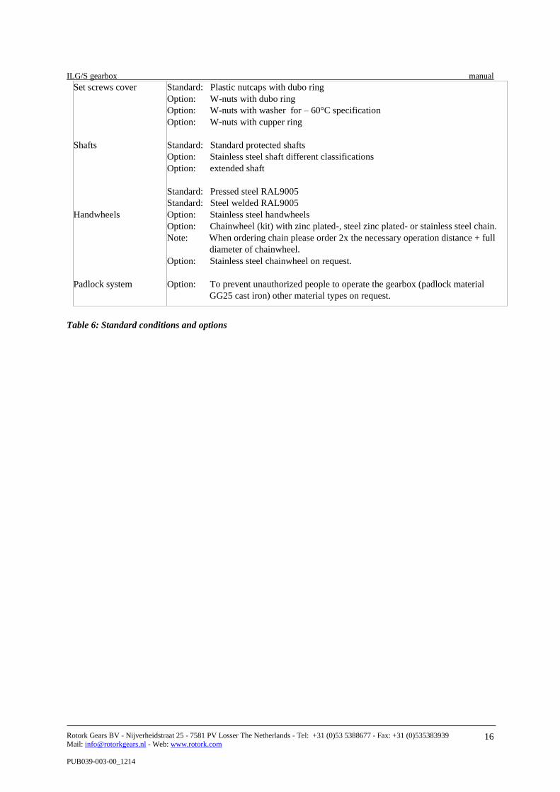
Set screws cover
Shafts
Handwheels
Padlock system
Standard: Plastic nutcaps with dubo ring
Option: W-nuts with dubo ring
Option: W-nuts with washer for – 60°C specification
Option: W-nuts with cupper ring
Standard: Standard protected shafts
Option: Stainless steel shaft different classifications
Option: extended shaft
Standard: Pressed steel RAL9005
Standard: Steel welded RAL9005
Option: Stainless steel handwheels
Option: Chainwheel (kit) with zinc plated-, steel zinc plated- or stainless steel chain.
Note: When ordering chain please order 2x the necessary operation distance + full
diameter of chainwheel.
Option: Stainless steel chainwheel on request.
Option: To prevent unauthorized people to operate the gearbox (padlock material
GG25 cast iron) other material types on request.
Table 6: Standard conditions and options

ILG/S gearbox manual
Rotork Gears BV - Nijverheidstraat 25 - 7581 PV Losser The Netherlands - Tel: +31 (0)53 5388677 - Fax: +31 (0)535383939
Mail: [email protected] - Web: www.rotork.com
PUB039-003-00_1214
17
10. IP Rating Solid Particle protection
The first digit indicates the level of protection that the enclosure provides against access to hazardous parts (e.g.,
electrical conductors, moving parts) and the ingress of solid foreign objects.
Level Object size protected against Effective against
6 Dust tight No ingress of dust; complete protection against contact
Liquid ingress protection
The second digit indicates the level of protection that the enclosure provides against harmful ingress of water.
Level Protected against Testing for Details
5 Water jets
Water projected by a nozzle (6.3 mm)
against enclosure from any direction shall
have no harmful effects.
Test duration: at least 3 minutes
Water volume: 12.5 litres per minute
Pressure: 30 kPa at distance of 3 m
6 Powerful water jets
Water projected in powerful jets (12.5
mm nozzle) against the enclosure from
any direction shall have no harmful
effects.
Test duration: at least 3 minutes.
Water volume: 100 litres per minute.
Pressure: 100 kPa at distance of 3m.
7 Immersion up to 1 m
Ingress of water in harmful quantity shall
not be possible when the enclosure is
immersed in water under defined
conditions of pressure and time (up to 1
m of submersion).
Test duration: 30 minutes
Immersion at depth of at least 1 m
measured at bottom of device, and at least
15 cm measured at top of device
8 Immersion beyond 1 m
The equipment is suitable for continuous
immersion in water under conditions
which shall be specified by the
manufacturer. Normally, this will mean
that the equipment is hermetically sealed.
However, with certain types of
equipment, it can mean that water can
enter but only in such a manner that it
produces no harmful effects.
Test duration: continuous immersion in
water
Depth specified
Table 7. IP rating

ILG/S gearbox manual
Rotork Gears BV - Nijverheidstraat 25 - 7581 PV Losser The Netherlands - Tel: +31 (0)53 5388677 - Fax: +31 (0)535383939
Mail: [email protected] - Web: www.rotork.com
PUB039-003-00_1214
18
11. Certificates Atex
Directive EC 94/9/EG states the directive only applies to equipment which is capable of causing an explosion
through its own potential sources of ignition. The gearboxes from type AB, 242, 232, 300, ILG/S and ILG/D
don’t have their own potential source of ignition, so directive EC 94/9/EG doesn’t apply. Therefore we state that:
Operation of gearboxes type series AB, 232 and 300 with the marking:
II 2 G D c 120 C
in areas with explosive gas atmospheres Zone I and II Category 2 (and 3)
and explosive dust atmospheres Zone 21 and 22 Categories 2 (and 3)
: this product meets the requirements for explosion prevention
II : in a potential explosive surrounding, other than in mines,
2 : with a high level of safety, based on normal operation and anticipated risks
G D : suitable for a possible explosive atmosphere caused by gases, vapours, mists of air/dust
mixtures
c : safety obtained by constructive solutions.
120C : indicating the maximum surface temperature in °C
Certificates of conformity
Rotork Gears BV certify that the Gearbox models AB, 242, 232 and 300 supplied conforms in all respects to our
specifications and have been subject to our Quality System conforming to BS EN IS09001:2008
Other certificates
For other certificates please contact our sales department, these are on request an need to be ordered in the
preliminary stages. The following certificates we can provide:
- EUR 1 certificate
- Certificate of origin
- GOST certificate
- Certificate of Conformity
- 2.2 certificate
- Long term supplier declaration

ILG/S gearbox manual
Rotork Gears BV - Nijverheidstraat 25 - 7581 PV Losser The Netherlands - Tel: +31 (0)53 5388677 - Fax: +31 (0)535383939
Mail: [email protected] - Web: www.rotork.com
PUB039-003-00_1214
19
12. Reach